1
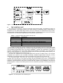
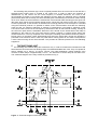
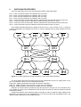
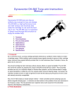
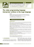
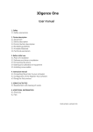
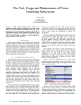
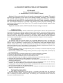
A LOW-COST SWITCH FOR AC-DC TRANSFER
M. Kampik
Silesian Technical University
ul. Akademicka 10, 44-100 Gliwice, Poland
Abstract: A low-cost switch for ac-dc transfer is presented in this paper. The switch
performs fast switching of the input of the thermal voltage converter (TVC) between
AC and DC calibrator outputs. It can be controlled through the GPIB bus, manually
and through the serial RS-232 interface. Both 4-wire and 2-wire connection between
the TVC and the calibrators is possible. The switch provides very fast switching. The
dead time of the switch is less than 5 ms. The switch is well protected against relay
and power failures.
Keywords: transfer switch, AC-DC transfer, thermal voltage converter
1
INTRODUCTION
Each thermal AC-DC voltage transfer measurement system requires a device which performs fast
switching of the input of the thermal voltage converter (TVC) between AC and DC calibrator outputs.
There are no commercially available switches on the market, which could be directly implemented in
the AC-DC transfer. An exception is the switch designed at OFMET [1]. Most laboratories use
switches of their own design and construction [2]. This diversity helps to detect eventual systematic
errors which can be caused by the switch. The switch presented in the paper is another approach.
2
REQUIREMENTS
The switches used in the AC-DC transfer can be generally divided into rotary- and relay type.
Usually the most expensive parts of a switch are the rotary switches or relays. From the economical
point of view it is important to fit these parts to the measurement needs. Well designed switch,
however, should allow an easy eventual replacement of existing rotary switches or relays by better
(and more expensive) ones, if the voltage or current AC-DC calibration requirements increase. The
switch presented in this paper fulfills the following requirements:
1° low cost;
2° switching capability: voltages up to approximately 350 V, currents up to 100 mA in frequency range
from 0 to approximately 1 MHz;
3° allows an easy replacement of existing switching elements by higher voltage rated (for example up
to 1100V and 20 A);
4° both 4-wire and 2-wire connection between the TVC and the calibrators is possible;
5° provides very fast switching. The dead time of the switch is less than 5 ms;
6° enters very small thermoelectric forces into the measured circuit;
7° can be controlled through the GPIB bus, manually and through a serial RS-232 interface;
8° the actual state of the relays is clearly indicated on the front panel;
9° during the measurement does not generate a high-frequency electromagnetic field which can
disturb the measurement;
10° is protected against power failures, which can enter an unexpectable state of the switching
elements. This may be dangerous to the expensive measuring equipment;
11° during power-on or power-off states the switch immediately enters a defined reset state at which
the TVC is disconnected from the calibrator outputs;
12° an output for a voltmeter is provided to measure the voltage at the output of each calibrator before
applying it to the input of the TVC.
3
THE SWITCH CIRCUITRY
The block diagram of the switch is shown in Fig. 1. It consists of two main units: the control unit
with the main controller, display, keyboard, both the interfaces, floating decoding and protection logic
and of a switching unit which contains relays. The switching unit is connected with the control unit
through a screened multiwire cable.
Figure 1. Block diagram of the switch
4
THE CONTROL UNIT
The control unit is based on a 8-bit microcontroller with internal UART. It simplified the design of
the serial interface. The transfer speed of the serial interface is selectable (2400 or 4800 baud). A
simplified low-cost GPIB (IEEE-488) interface chip was designed and implemented using FLASHmemory-based complex programmable logic device (CPLD). It contains no clock to avoid an emission
of interferences. The functions supported by the interface are listed in table 1.
Table 1. Supported IEEE-488 interface function set.
Interface Function
SH1
AH1
T8
L4
RL1
DC1
Description
Complete source handshake capability
Complete acceptor handshake capability
Basic talker; no serial poll; no talk-only mode; unadress if MLA
Basic listener; no listen-only mode; unadress if MTA
Full remote/local capability including local lockout
Device clear capability
It is possible to identify the switch controller and get the information about the actual state of the
relays by sending the appropriate query command. The program steering the microcontroller is stored
in an erasable programmable read- only memory (EPROM). It allows any modification of the control
program. The keyboard on the front panel allows manual operation of the switch. The actual state of
relays is clearly displayed on a liquid crystal display (LCD) and with light emitting diodes (LEDs). The
front panel of the switching unit is shown in Fig. 2.
The user can configure the most important parameters through the MENU option. The selected
parameters are stored in the nonvolatile electrically erasable programmable read-only memory
(EEPROM). The selected parameters remain unchanged even if the switch is powered off.
The 5-bit-wide digital word from the control unit is decoded by means of a 5-line-to-24-line
decoder. Up to 12 two-coil or 24 single-coil relays may be controlled by this circuit. A combinatorial
protection circuit was added to exclude unexpectable states that may be dangerous for the measuring
equipment. Special attention was paid to ensure that the outputs of the calibrators will never be
shorted together. A delay circuits always disconnect one calibrator input before connecting the input of
the other.
Figure 2. The front panel of the switching unit.
The decoding and protection logic circuit is optically isolated from the control unit circuit and has a
separate power supply which is located in the control unit. In order to reduce the emission of
interferences by the control unit the clock frequency is lowered. Moreover, the clock of the
microcontroller is turned on only during the switching process. When the switching action is finished
(what usually takes few seconds), the microcontroller goes automatically into the STOP mode, turning
off its clock. When the serial interface is selected the microcontroller after switching process goes into
idle state, which leaves microcontroller internal clocks, serial port and timers running but no memory
access is performed, so the emission of interferences is strongly reduced. If the serial port is controlled
using the RTS/CTS protocol it is possible to switch off the microcontroller clock after the switching
action as well. An enhanced reduction of emission of interferences is provided by switching off the
LCD. Most LCDs are sources of low-frequency interferences due to their internal clocking. Turning off
the LCD is an option which is selectable. When the LCD is turned off, the actual state of the relays is
indicated by the LEDs on the front panel and the switch contains no internal clocks during the
measurement time. The only exception is the serial port controlling mode without RTS/CTS protocol.
During power on the switch resets automatically and enters the OFF2 state. During the operation a
power fail circuit causes a reset in case of a power failure. During power off, the same circuit performs
a reset before turning off the microcontroller. This provides an ultimate protection for the calibrating
equipment.
5
THE SWITCHING UNIT
The switching unit contains relays and connectors only. In order to minimize the transition time and
thermoelectric forces fast two-coil latching relays from Matsushita-NAIS are used. They are capable to
switch voltages up to 350 VDC at current 100 mA. The initial breakdown voltage between open
.
contacts of these relays is approximately 1 kVRMS . The dead time of these relays is less than 5 ms.
The schematic diagram of the relay module is presented in Fig. 3.
Figure 3. Schematic diagram of the relay module
6
SWITCHING PROCEDURES
There are eight states of the TVC output and three states of the DVM output:
AC2 - 2-wire connection between AC calibrator and TVC input;
DC2 - 2-wire connection between DC calibrator and TVC input;
AC4 - 4-wire connection between AC calibrator and TVC input;
DC4 - 4-wire connection between DC calibrator and TVC input;
OFF1 - 2-wire AC/4-wire DC reset state, both the calibrators are disconnected from the TVC input;
OFF2 - 2-wire reset state, both the calibrators are disconnected from the TVC input;
OFF3 - 4-wire AC/2-wire DC reset state, both the calibrators are disconnected from the TVC input;
OFF4 - 4-wire reset state, both the calibrators are disconnected from the TVC input.
The possible transitions between the states are shown in Fig. 4. As it is shown in Fig. 4, change of
a wiring configuration (for example from 2-wire to 4-wire) is possible only by going through one of the
OFF states.
Figure 4. Possible transitions (arrows) between the TVC output states (bubbles)
The three states describing the DVM output are fully independent of the TVC output state. At any
time it is possible to select one of the following DVM state:
DVM_OFF - digital voltmeter disconnected from both the calibrators;
DVM_AC - digital voltmeter connected to the output of the AC calibrator;
DVM_DC - digital voltmeter connected to the output of the DC calibrator;
Selection of a desired state is possible through the keyboard or through one of the interfaces (only
one available at a time). The commands that must be sent over the bus to select a particular state are
presented in Table 2.
A delay time between some switching steps is provided in order to settle the output voltage of the
calibrators. This delay time is user-selectable from 0.1 to 9.9 seconds through the MENU function. The
selected value is stored in the non-volatile memory.
Table 2. Commands selecting the TVC and DVM output states.
TVC output commands
OFF
DC
AC
Configuration commands
2-WIRE AC
4-WIRE AC
2-WIRE DC
4-WIRE DC
DVM output commands
DVM_AC
DVM_DC
DVM_OFF
7
Command
OFF
DC
AC
Command
2AC
4AC
2DC
4DC
Command
DVMAC
DVMDC
DVMOFF
Comments
forces actual OFF state
connects DC calibrator to TVC
connects AC calibrator to TVC
Comments
executable only in OFF state
executable only in OFF state
executable only in OFF state
executable only in OFF state
Comments
connects DVM to AC calibrator
connects DVM to DC calibrator
disconnects DVM
POSSIBLE ENHANCEMENTS AND MODIFICATIONS
The switch design allows an easy replacement of existing relays by other. The voltage supplying
the relay coils can be set in the range from 1.2 to 24 V. Therefore the existing relays can be replaced
by high-voltage and high-current type (for example from Kilovac) or by high-frequency type (for
example from Teledyne).
ACKNOWLEDGMENT
The work was supported by the Polish State Committee for Scientific Research.
REFERENCES
[1] Short User’s Manual of the 4 or 2 wire automated AC/DC switch. Swiss Federal Office of
Metrology, Wabern 1996.
[2] M. Klonz, CCE comparison of AC - DC voltage transfer standards at the lowest attainable level of
uncertainty, IEEE Trans. Instrum. Meas., 46 (2) (1997) 342-346.
AUTHOR: Ass. Prof. Dr. Marian KAMPIK, Institute of Electrical Measurements and Control, Silesian
Technical University, ul. Akademicka 10, 44-100 Gliwice, Poland
Phone Int. ++48 32 237 1769, Fax Int. ++48 32 237 2034, E-mail: [email protected]