1
INTREPID User Manual
Library | Help | Top
Old Gridding (T22)
1
| Back |
Old Gridding (T22)
Top
We have replaced with this tool wih a new Java platform tool. See Gridding (T22a).
The new tool has extended features and a superior user interface.
For a limited time we continue to support the older tool described in tbis chapter.
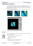
This tool enables you to convert point and traverse line data to a grid suitable for
image processing and contouring. INTREPID divides the region being processed into
a grid of square cells. Each grid cell will contain a value derived from an original data
point (an original data cell) or interpolated from neighbouring cells or nearby points
(an interpolated cell).
You can also use the INTREPID Gridding tool to enhance an existing grid dataset
using LaPlace convolution and Minimum Curvature.
Beside the Gridding tool and the Spreadsheet Editor INTREPID has two special grid
dataset processing tools and a grid rotation facility.
•
The Grid Operations tool can resample the grid and change the cell size, See Grid
Operations (T25) for information about this tool.
•
The INTREPID Grid Stitch tool can combine overlapping or adjacent grid
datasets, correcting for differences between them. It can also display data profile
graphs along paths that you trace on the display. See Grid Stitch—combining two
grids (T23) for a full description.
•
The INTREPID Projection Conversion tool can rotate the cells of a grid so that the
rows of cells are oriented differently. See Old Datum and Projection Conversion
(T12) for instructions.
Recent changes to the Gridding tool
We have substantially rewritten the Gridding tool. You will notice some differences
in its operation, but the new version has a similar user interface to the old one. We
will rewrite the Reference Manual chapter for the new tool in the next edition.
This section summarises the changes to the tool. It has
Library | Help | Top
•
Rewritten internal coding to increase its efficiency and ease of modification.
•
Tiling during bi-cubic spline (including trend spline) gridding and therefore use
this process with grids of unlimited size.
•
Rearranged grid enhancement options to allow you more control of the process.
•
A choice of Akima or Cubic spline gridding (displays a dialog box for you to
choose).
•
Enhanced trend splining technique for line data. See Enhanced trend splining.
•
Gridding wizard. This simplifies the gridding process. It takes you through the
stages of the process, requesting parameters and choices in the correct order. See
Gridding wizard.
•
Gridding of potential field data plus observed gradients. See Gridding of potential
field data with observed gradients.
•
Enhanced potential (TMI or Gravity) field grid, honouring observed gradients. See
Enhanced potential field gridding.
© 2012 Intrepid Geophysics
| Back |
INTREPID User Manual
Library | Help | Top
Old Gridding (T22)
2
| Back |
Enhanced trend splining
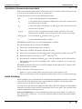
If you have selected Trend gridding, after you choose Apply, a dialog box appears for
specifying trend gridding parameters.
The process finds maxima and minima in adjacent lines and associates them.
High Pass Window INTREPID applies a high pass filter to the data before
examining trends. This filter is in the form of a moving average. INTREPID uses
the residual values from this moving average filter. You can specify the size (in
grid cells) of the window for the filter.
Minimum Amplitude for trending INTREPID will not process maxima or minima
with amplitude less than the value1 you specify here
Strike Angle Limit INTREPID will not record trends at angles closer to the line
direction than the angle you specify here. Trends close to the line direction are too
hard to follow using the trend gridding method because of the oblique distances
between the lines. Trends in the line direction do not need enhancement, in any
case.
Save Generated Trend Points To save the additional trend points, turn on this
check box and specify the name for the additional trend points dataset.
This option replaces the use of the INTREPID_TREND_POINTS system
parameter and the procedure described in Recording the additional trend points.
Gridding wizard
1. in Z units, for example, nT
Library | Help | Top
© 2012 Intrepid Geophysics
| Back |
INTREPID User Manual
Library | Help | Top
Old Gridding (T22)
3
| Back |
Gridding of potential field data with observed gradients
In the Gridding Wizard, specify Vector type input.
Sign convention for gradients from an aircraft
There is a local coordinate convention associated with acquisition. Since we are
dealing with vector components of the potential field, this convention must be
applied.
Assuming a moving platform for the acquisition vehicle such as an aeroplane:
•
The local Y positive or length component is tail to tip positive.
•
The cross component is left to right positive.
•
The vertical component is upwards positive.
Storage of gradients in the source dataset
The gridding algorithm accepts any or all of these vector gradients.
Before gridding, convert the differences between readings to nT/m. Divide the
difference by the distance between instruments
The local heading of the observation is also computed from the X, Y data and the
components are stored with each scalar field observation as vector components in the
E, N & Vertical projection system. That is, the observations are stored in a
normalized coordinate frame for internal use.
Opportunities for using this extra gradient data
•
Direct gridding of observed analytical signal
δT-⎞
⎛ δT
⎛ ----⎛ δT
------⎞
------⎞
⎝ δx ⎠ + ⎝ δy ⎠ + ⎝ δz ⎠
2
•
2
2
Direct gridding of observed total horizontal gradient, i.e.
2
2
⎛ δT
------⎞ + ⎛ δT
------⎞
⎝ δx ⎠
⎝ δy ⎠
Library | Help | Top
•
Enhanced potential (TMI / Gravity) field grid, honouring observed gradients. (see
Enhanced potential field gridding)
•
For TMI, calculation of a short wavelength diurnal variation.
© 2012 Intrepid Geophysics
| Back |
INTREPID User Manual
Library | Help | Top
Old Gridding (T22)
4
| Back |
Enhanced potential field gridding
This has three stages:
Akima splines
These are able to take an observed gradient along the spline direction. The line
direction gradient component is calculated for each observation point as required.
Minimum Curvature algorithm
Brigg's formulation is a first order finite difference approximation of La Place
condition (13 point kernel). This went to considerable trouble to remove any observed
horizontal gradient components.
This traditional formulation is revisited and redone as a second order finite difference
approximation (25 point kernel). Provision for observed gradients has also been
made.
Trend gridding
This allows the possibility of estimating key new pseudo observation points between
flight lines. This estimation of observed value plus gradients is then available for the
2nd pass Akima spline.
Natural Neighbour gridding
This alternative method also allows for observed gradients. No implementation of
this is available as yet.
Library | Help | Top
© 2012 Intrepid Geophysics
| Back |
INTREPID User Manual
Library | Help | Top
Old Gridding (T22)
5
| Back |
Using the Gridding tool
>> To use Gridding with the INTREPID graphic user interface
Library | Help | Top
1
Choose Gridding from the Grid menu in the Project Manager, or use the command
gridding.exe. INTREPID displays the Gridding Main window.
2
If you have previously prepared file specifications and parameter settings for
Gridding, load the corresponding task specification file using Load Options from
the File menu. (See Specifying input and output files for detailed instructions.) If
all of the specifications are correct in this file, go to step 10. If you wish to modify
any settings, carry out the following steps as required.
3
If you are producing the grid from line data, ensure that INTREPID will be able to
adequately identify the acquisition lines. See Identifying acquisition lines for
details.
4
Specify the Z field for gridding from the line or point dataset, or the grid dataset to
be reprocessed. Use Load Z Field for Gridding or Load Grid for Reprocessing from
the File menu. See Specifying input and output files for detailed instructions.
5
If you wish to restrict the process to a specific region, specify the polygon dataset
which defines the region. Use Load Polygon (Sub Region) from the File menu.
See Restricting the process to a specified region for further information.
6
If you wish to save the resulting grid, or if INTREPID requires you to specify a file
because the grid is too large for your computer's memory, specify the output grid
dataset. Use Specify Output Grid from the File menu. If the grid is not too large
for the computer's memory, you can complete the gridding process and decide to
save the resulting grid afterwards if you wish. (See Specifying input and output
files and Storage of completed grids, memory limits, large grids, output files).
7
If you are continuing an unfinished gridding process that involves tiling, or
otherwise wish to specify a range of tiles to be processed, switch to the Gridding
Tiling Control window (Choose Tiling from the Window menu), ensure that
Manual Tiling Control is turned on, and specify the range of tiles to be processed.
See Specifying the range of tiles to be processed for details.
© 2012 Intrepid Geophysics
| Back |
INTREPID User Manual
Library | Help | Top
Old Gridding (T22)
6
| Back |
8
If you are producing a grid from a line or point dataset, specify
•
Z Field Pre-processing (if required) (See Pre-processing the Z data);
•
Precision of data in the output grid (See Specifying the precision of data in the
output grid);
•
Grid Cell Size (See Specifying the grid size);
•
Cell extrapolation limit (See Cell extrapolation limits);
•
Nominal Bearing of line data and grid rotation (if required) (See Nominal Bearing
and Producing a rotated grid);
•
Initial gridding method and required parameters (See Initial Gridding).
9
Specify the Image Refinement options (LaPlace convolution, Minimum Curvature,
Smoothing, Masking) and corresponding parameters as required (See Image
Refinement for details).
10 Turn Show Gridding on or off as required (Show Gridding is normally turned on).
See Viewing the gridding progress and clearing the display for instructions.
11 When you have made specifications and settings according to your requirements,
choose Apply. INTREPID will perform the Gridding process. If you have turned
on Show Gridding and selected the Gridding Main window, INTREPID displays
the new grid as it is produced.
•
If you are processing a small grid that fits into memory, and have specified an
output grid file, INTREPID will save the grid at the end of the process.
•
If you are processing a small grid that fits into memory, and have not specified an
output grid file, INTREPID will save the completed grid immediately if you now
specify the output file. See Specifying input and output files for information about
specifying files.
•
If you are processing a large grid and using the tiling process, INTREPID will
save each tile on completion. See Storage of completed grids, memory limits, large
grids, output files for information about memory and tiling.
12 If you wish to record the specifications for this process in a task specification
(.job) file in order to repeat a similar task later or for some other reason, use
Save Options from the file menu. (See Specifying input and output files for
detailed instructions.)
13 If you wish to repeat the process, repeat steps 2–12, varying the parameters and/
or data files as required.
Library | Help | Top
© 2012 Intrepid Geophysics
| Back |
INTREPID User Manual
Library | Help | Top
Old Gridding (T22)
7
| Back |
14 To exit from Gridding, choose Quit from the File menu.
To view the current set of specifications and a report of the process and files involved,
choose Report from the Window menu. INTREPID displays the Gridding Report
window. See Displaying options and using task specification files for details and an
example of a set of specifications.
After using Gridding you can carry out a more detailed inspection of the grid using
INTREPID visualisation tools (see Visualisation (T26)).
You can clear the Gridding Main window display at any time using Clear from the
Display menu.
You can view Help information by choosing options from the Help menu (See Help).
You can execute Gridding as a batch task using a task specification file that you have
previously prepared. See Displaying options and using task specification files for
details.
If you are executing Gridding as a batch task you can modify the task specification
file to
•
Disable the clipping of extrapolated cells from the outside the row and column
limits of the grid (See (Clipping / Crew Cut) for details)
•
Modify the relaxation factor (See Minimum Curvature for details).
Summary of the gridding process
1
If you are gridding line or point data, you specify the field of Z data
If you are enhancing an existing grid, you specify the grid dataset name and go to
step 6.
2
You specify processes and parameters that you require.
3
INTREPID performs Z field pre-processing.
4
INTREPID calculates the number of cells in the grid, based on the extent of the
line or point data.
5
INTREPID calculates centroid values for original data cells.
6
INTREPID calculates centroid values for interpolated cells (that do not contain
original data), using the Nearest Neighbours, Bi-Cubic Spline, Trend Spline or
Box Filter methods.
7
INTREPID performs LaPlace smoothing as required.
8
INTREPID performs the Minimum Curvature smoothing process as required.
9
INTREPID performs the Masking and/or Clipping process as required.
10 INTREPID saves the grid if required, or saves the current tile and goes back to
repeat the process for the next selected tile.
Library | Help | Top
© 2012 Intrepid Geophysics
| Back |
INTREPID User Manual
Library | Help | Top
Old Gridding (T22)
8
| Back |
Specifying input and output files
To create grids from point or traverse line data, you must specify the Z field to be
gridded. To reprocess an existing grid, you will need to specify the name of the grid
and the band number to be processed.
You may also wish to specify
•
(If you wish to grid only a particular region), the polygon dataset (geographical
region) required. (See Restricting the process to a specified region).
•
(If you wish to save the results of the gridding process) the name for the output
dataset (See Storage of completed grids, memory limits, large grids, output files
for details).
INTREPID obtains the X, Y and line type data from the dataset aliases. You must
have the following aliases identifying appropriate fields:
Alias
Field
X
East–West geographic location coordinate
Y
North–South geographic location coordinate
LineType
Line type
PointType
Point quality
See "Vector dataset field aliases" in INTREPID database, file and data structures
(R05) for more information about aliases.
Choose the options as required from the File menu.
In each case INTREPID displays an Open or Save As dialog box. Use the directory
and file selector to locate the file you require. (See "Specifying input and output files"
in Introduction to INTREPID (R02) for information about specifying files).
Load Z Field for Gridding If you are gridding from a line or point dataset, use this
to specify the Z field to be gridded.
If the alias does not exist, INTREPID displays Load X, Load Y and Load LineType
(line datasets only) dialog boxes one after the other as required, for you to specify
these fields. If there is no line type field, choose Cancel in the Load LineType
dialog box.
For point datasets, if there is no PointType alias, then INTREPID does not use
point type in selecting points for gridding.
Library | Help | Top
© 2012 Intrepid Geophysics
| Back |
INTREPID User Manual
Library | Help | Top
Old Gridding (T22)
9
| Back |
Load Grid for Reprocessing If you are refining an existing grid, use this to specify
the grid file name. INTREPID will only load and process band 0 of this grid (See
Output grid bands specification for more information about bands).
Load Polygon (Sub Region) Use this to specify a polygon dataset which will act as
a region of interest for the gridding process. INTREPID will only grid data
within the polygon. See Restricting the process to a specified region for details.
Specify Output Grid If you wish to save the resulting grid, or if it is a large grid
that requires tiling (See Storage of completed grids, memory limits, large grids,
output files for details), use this option to specify the grid name. The output grid
may be a new or existing grid. You can select the file name of an existing grid in
the Save As dialog box, for example if you are
•
Overwriting a grid,
•
Processing selected tiles of an existing grid or
•
Saving to a band of an existing grid.
After you specify the grid name INTREPID displays the Band Selection dialog
box. Specify the band numbers and choose OK. See Output grid bands
specification for details.
The origin of a grid saved by this tool is the centroid of the pixel/cell in the top left
hand corner.
See Storage of completed grids, memory limits, large grids, output files for details
about the timing of the save process.
Load Options If you wish to use an existing task specification file to specify the
Gridding process, use this menu option to specify the task specification file
required. INTREPID will load the file and use its contents to set all of the
parameters for the Gridding process. (See Displaying options and using task
specification files for more information).
Save Options If you wish to save the current Gridding file specifications and
parameter settings as an task specification file, use this menu option to specify
the filename and save the file. (See Displaying options and using task
specification files).
Identifying acquisition lines
This section is for line dataset gridding only. It is normal practice to use only
acquisition lines in the gridding process for line data.
Identifying acquisition lines using a line type field
If there is a LineType alias or if you specify a line type field in response to a prompt,
INTREPID will use it to automatically exclude non-acquisition line data, processing
types 2 and 3 only See "Traverse line numbers and types" in INTREPID database, file
and data structures (R05) for a complete list of traverse line types and numbers.
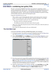
If your dataset does not have a line type field but does have line numbers from which
you can derive a line type field, you can use the INTREPID Spreadsheet Editor
facility to create it. See "Create new field example—Line Type field" in Spreadsheet
Editor (T15)) for details about creating line type fields.
Library | Help | Top
© 2012 Intrepid Geophysics
| Back |
INTREPID User Manual
Library | Help | Top
Old Gridding (T22)
10
| Back |
Identifying acquisition lines using Nominal Bearing
If you do not specify a line type field, but you do specify a Nominal Bearing (estimate
of the strike (orientation) of the acquisition lines), INTREPID will identify the
traverse lines oriented within ±22½° of the Nominal Bearing as acquisition lines.
INTREPID uses the start and end points of a traverse line to calculate its strike.
If you wish to use the Nominal Bearing setting to identify the acquisition lines, but do
not know their strike, INTREPID can calculate the average strike of the dataset for
you. See Nominal Bearing for instructions.
If you do not identify acquisition lines
If you do not specify a line type field or a nominal bearing, INTREPID will grid all
traverse line data.
Point quality
This section is for point dataset gridding only. If there is a PointType alias or you
have specified a point type field, INTREPID will grid only those points for which the
point type = 1. If you have not specified a point type field, INTREPID will grid using
all points.
Output grid projection
The projection of the output grid is the same as that of the source dataset. See Old
Datum and Projection Conversion (T12) for information about changing projection.
Output grid bands specification
Grids may have a number of sets of values, or bands. INTREPID stores multiband
grid datasets in Band Interleaved by Pixel format13.
The Gridding tool can work with one band only at a time.
After you specify an output grid file name INTREPID displays the Band Selection
dialog box.
Use this dialog box to specify the number of bands for the grid, and which band you
intend to process (the current band). The band information consists of two numbers
separated by /. The first number is number of bands in the grid. The second number
is the band number for the current grid. The bands are numbered from 0. The
default number of bands is 1, and the default current band is 0.
After you have specified the band numbers, choose OK. See "Multiband grid datasets"
in INTREPID database, file and data structures (R05) for more information.
Note: If you are using Gridding to enhance an existing grid, the current version of
INTREPID will load and process band 0 of the grid. You can still save the results of
the process to any band of another grid.
1.3 For details about Band Interleaved formats contact our technical support service.
Library | Help | Top
© 2012 Intrepid Geophysics
| Back |
INTREPID User Manual
Library | Help | Top
Old Gridding (T22)
11
| Back |
Storage of completed grids, memory limits, large grids, output files
For small grids, if you specify an output dataset, INTREPID will save it when the
gridding process is complete. If you do not, INTREPID will simply retain the grid in
memory until you perform another gridding process or exit from Gridding. If you
specify an output dataset after the gridding process is complete, INTREPID will save
the grid immediately.
For large grids you must specify a filename because your computer may not have
room in memory for the whole dataset. In this case, INTREPID divides the grid up
into sections (tiles), and processes them separately.
The criterion for a grid to be classified as large and require tiling is the value of the
system parameter INTREPID_MEMORY. "INTREPID Memory limits and tiling" in
Configuring and using INTREPID (R04) and INTREPID system parameters and
install.cfg (R07) for further information.
Restricting the process to a specified region
You can specify a region of interest for the Gridding process using a polygon dataset.
INTREPID will only grid data within the region defined by the polygon. You can use
the Subsection tool to define the polygon (See Subsections of datasets (T21) for full
instructions).
>> To specify a region of interest using a polygon dataset
Choose Load Polygon (Sub Region) from the File menu and select the polygon dataset
required.
Specifying the range of tiles to be processed
If you are continuing an unfinished gridding process that involves tiling, or otherwise
wish to specify a range of tiles to be processed, you can do this as follows.
>> To specify the range of tiles to be processed
Library | Help | Top
1
Switch to the Gridding Tiling Control window (Choose Tiling Control from the
Window menu).
2
Turn on Manual Tiling Control. INTREPID displays the tile range text boxes.
3
Specify the range of tiles to be processed in the corresponding text boxes.
© 2012 Intrepid Geophysics
| Back |
INTREPID User Manual
Library | Help | Top
Old Gridding (T22)
12
| Back |
Pre-processing the Z data
If you are gridding traverse line data you can apply a range of processes to the Z data
before commencing the gridding process.
You can choose one of the following
•
A Convolution filter for smoothing the data,
•
A Naudy filter for noise reduction,
•
Quadrature
•
Instantaneous Phase
•
Instantaneous Frequency
•
Automatic Depth Estimation
An explanation of each of these processes appears below.
>> To specify pre-processing
1
Choose Z Field Pre-Process from the Pre-Process menu. INTREPID displays the
Z Field Pre-Process dialog box.
Select the process you require from the Process option buttons. The default
process is None.
2
If you have selected Convolve, specify the size of the convolution window in data
points, using the Window Size (data points) text box. See Convolve for an
explanation.
3
If you have chosen the Naudy filter, specify
•
The filter wavelength (in data points) using the Window Size (data points) text
box,.
•
The filter tolerance (in Z units) using the Tolerance text box,
•
Whether you wish to produce the grid from the corrected data or from the data
rejected by the filter (i.e., the noise).
See Naudy for an explanation.
4
If you have chosen Automatic Depth Estimation, specify Window Size (data
points). See Automatic Depth Estimation for an explanation.
5
Choose OK. INTREPID will note your choices and use them during the Gridding
process.
The following sections describe each pre-process and its parameters in more detail.
Library | Help | Top
© 2012 Intrepid Geophysics
| Back |
INTREPID User Manual
Library | Help | Top
Old Gridding (T22)
13
| Back |
Convolve
This is a filter for smoothing the data. For each point, INTREPID will compare each
Z value with neighbouring values along the line. If there are sudden changes,
INTREPID will adjust the current Z value to make the changes smooth. You need to
specify the following:
Window Size (data points) Use this to specify the number of data points to be
compared around the point being adjusted. For example, if you set the window to
4, INTREPID will examine two points on each side of the current point to
calculate any adjustment. The default value of this parameter is 2.
Naudy
This filter reduces noise in your data by detecting sudden changes or spikes that are
not characteristic of potential field data. You need to specify the following:
Window Size (data points) Use this to specify the wavelength (in data points) for
the Naudy filter. The wavelength corresponds to the maximum width of noise
anomalies to be removed. INTREPID will remove anomalies shorter than the
wavelength you specify. The default value is 2.
Tolerance Use this to specify the filter tolerance (in Z units). The tolerance
corresponds to the minimum amplitude of suspected noise anomalies to be
removed. INTREPID will remove spikes with a amplitude higher than the
tolerance you specify. The default value 0.1 corresponds to 0.1nT, the current
documented accuracy of magnetometers. This ensures that INTREPID will only
remove noise, and not waste time attempting to smooth out the normal
fluctuations associated with the precision limits of the instrument.
Naudy Filter Options Select Use Corrected Data to produce the grid from the
corrected data. Select Use Rejected Data (Noise) to produce the grid from data
rejected by the filter (the 'noise').
Quadrature
This is an imaginary component of the Z field signal derived using the Hilbert
transform 19 point finite difference operator. It is used to calculate instantaneous
phase. This option is provided so that you can view the Quadrature results if
required.
Instantaneous Phase
This is derived by combining the Z data (real component) and the Quadrature results
(imaginary component) using the formula
imaginary
instantaneous phase = atan ⎛⎝ ------------------------⎞⎠
real
Instantaneous Phase can show continuity for subtle features often lost when you only
examine the real component. See the articles Taner, Koehler and Sheriff (1979)14
and Fitzgerald, Yassi, and Dart (1997)25 for further discussion of this technique.
1.4 Taner, M.T., Koehler, F. and Sheriff, R.E., 1979, Complex seismic trace analysis:
Geophysics 44, 1041–1063.
2.5Fitzgerald, D., Yassi, N. and Dart, P., 1997, A case study on geophysical gridding
techniques: INTREPID perspective: Exploration Geophysics, 28, 1–
Library | Help | Top
© 2012 Intrepid Geophysics
| Back |
INTREPID User Manual
Library | Help | Top
Old Gridding (T22)
14
| Back |
Instantaneous Frequency
This is a measure of change in the Instantaneous Phase (see previous section),
comparing adjacent values of Instantaneous Phase results. It uses the formula
instantaneous frequency = diff1(instantaneous phase)
See DIFF function example for an illustration of this function.
Automatic Depth Estimation
This process uses the Phillips method to estimate from the Z field signal the depth to
a magnetic basement. INTREPID expresses the results in the same units as the X
and Y fields of the dataset. Depth Estimate values are negative numbers with 0
corresponding to the survey height.
Window Size (data points) We suggest a value of 20 for this parameter.
Specifying the precision of data in the output grid
>> To specify the precision for the resulting gridded data
Choose the required option from the Precision menu.
The following table gives details of the Precision menu options
Menu Option
Detail
Byte
Byte
Integer (16 bit)
Single precision integer
Float (32 bit)
Single precision floating point
Double (64 bit)
Double precision floating point
See "Data Types in INTREPID datasets" in INTREPID database, file and data
structures (R05) for general information about precision in INTREPID datasets.
Library | Help | Top
© 2012 Intrepid Geophysics
| Back |
INTREPID User Manual
Library | Help | Top
Old Gridding (T22)
15
| Back |
Specifying the grid size
Use the Grid Cell Size text box in the Gridding Parameters area to specify the size of
one grid cell in the distance units of the dataset.
Setting an appropriate Grid Cell Size is a balance between having a fine 'mesh' grid
and having gaps or excessive interpolation between cells which may lead to
inaccuracies.
If you are gridding from a line dataset we recommend a cell size greater than a
quarter of the line spacing.
If you have a smaller cell size than recommended, we suggest that you increase the
cell extrapolation limit (See Cell extrapolation limits for details).
Note: If your dataset is geodetic (latitude and longitude) you need to specify the grid
cell size in degrees.
Cell extrapolation limits
You need to specify cell extrapolation limits for a number of Gridding processes:
Library | Help | Top
•
At the start of the gridding process INTREPID creates edge regions around the
original data cells. These regions will contain extrapolated / interpolated data.
The edge regions should ideally meet or overlap to satisfactorily fill gaps between
original data points (e.g., the gap between traverse lines, or the gap between
points of a point dataset). You need to specify appropriate cell extrapolation
limits for filling these gaps.
•
The image refinement processes also require an edge region containing data
around the whole grid. See Image Refinement for details.
•
The data in the edge region around the outside of the grid may be discarded after
the image refinement processes. This process is called Clipping. See (Clipping /
Crew Cut) for details.
•
INTREPID interpolates values for all cells within regions fully enclosed by but
outside the edge regions. The Masking process deletes (sets to null) these regions
if required. Masking needs to know the extent of the edge regions. (See Masking
for details).
© 2012 Intrepid Geophysics
| Back |
INTREPID User Manual
Library | Help | Top
Old Gridding (T22)
16
| Back |
>> To specify the cell extrapolation limit
Enter the limit (number of cells away from an original data point) into the
Extrapolate Cell parameter.
You should normally use an extrapolate cell value of at least 2. The default value is 2.
Nominal Bearing
This section is for line dataset gridding only. If you are gridding a field from a line
dataset using Bi-Cubic Spline or Trend Spline, INTREPID needs to know the
orientation of the acquisition lines.
If you are gridding a field from a line dataset using Nearest Neighbours or Box Filter,
you can specify the orientation of the acquisition lines for the purposes of quality
control (i.e., rejecting lines that have different orientation) or to specify rotation for
the grid.
INTREPID compares the Nominal Bearing parameter with acquisition line
orientation. It uses the parameter for the following purposes:
•
Determining the line direction for Bi-Cubic Spline and Trend Spline initial
gridding. See Initial gridding—Bi-Cubic Spline and Initial gridding—Trend
Spline below.
•
Identifying acquisition lines if there is no line type field. See Identifying
acquisition lines using Nominal Bearing for more information.
•
Acquisition line quality control: INTREPID will only process traverse lines whose
direction is within ±22½° of the specified Nominal Bearing. This rule applies
irrespective of the acquisition line identification method (See Identifying
acquisition lines).
•
Specifying the required angle for a rotated grid if you have acquisition lines that
do not lie North–South or East–West. See Producing a rotated grid.
Using average strike for the Nominal Bearing
You can use the average strike of the lines as the Nominal Bearing. INTREPID can
automatically calculate the average strike (orientation) of the traverse lines in the
dataset for you .
Library | Help | Top
© 2012 Intrepid Geophysics
| Back |
INTREPID User Manual
Library | Help | Top
Old Gridding (T22)
17
| Back |
>> To calculate the average strike for the current line dataset
1
Choose Report from the Window menu.
2
Choose Calculate Average Strike. INTREPID will calculate the average strike for
the dataset and display the result under the Calculate Average Strike button.
You can enter this result as the Nominal Bearing parameter.
Specifying Nominal Bearing
>> To specify Nominal Bearing
Use the Gridding Parameters area of the Gridding Main window.
Specify this parameter in the text box provided. Nominal Bearing can range from 0 to
180 and represents the bearing in degrees. 0° and 180° indicate North–South bearing
and 90° indicates East–West.
Producing a rotated grid
You may be gridding a field from a line dataset with 'oblique' acquisition lines (that
do not lie North–South or East–West). The survey may have been created like this,
for example, so that the data is perpendicular to the strike of a feature of interest.
You may wish to produce a rotated grid from 'oblique' data with its rows or columns in
the direction of the acquisition lines. After producing the grid you can rotate it so
that the rows lie East–West. See "Rotating a grid" in Grid Operations (T25) for
instructions.
If you are gridding an 'oblique' line dataset using the Bi-Cubic Spline or Trend Spline
method in the gridding process, you must produce a rotated grid.
With the Nearest Neighbours and Box Filter methods producing a rotated grid from
an 'oblique' line dataset is not compulsory. (See Initial Gridding.)
Library | Help | Top
© 2012 Intrepid Geophysics
| Back |
INTREPID User Manual
Library | Help | Top
Old Gridding (T22)
18
| Back |
>> To specify a rotated grid from 'oblique' acquisition lines
1
Specify the orientation for the grid rows as the Nominal Bearing parameter.
2
Turn on the Rotate Line Data check box in the Gridding Parameters area.
Grid initialisation
The first stage of gridding involves three processes.
1
INTREPID reads the input data. If it is a vector dataset, INTREPID creates a
grid data structure and aligns it with the source dataset.
2
INTREPID identifies the grid cells that contain one or more original data points.
It finds the nearest data point to the cell centroid and assigns its Z value to the
cell. It also records the 'exact'16 position of the original data point within the cell
for 'honour original points' processes.
3
INTREPID determines the row and column limits for the grid. INTREPID uses
the cell extrapolation limit and the original data cells at the ends of each row and
column in this process.
Note: The origin of a grid is the centroid of the pixel/cell in the top left hand corner.
Recording the cell centroid and original data point positions
You can save the cell centroids and the 'exact' positions of original data points
selected for use (the sample points). We have provided this option for technical
auditing of the gridding process.
>> To save the cell centroid and sample point exact positions
Assign a value to the system parameter INTREPID_HONOUR_ORIGINAL before
processing. INTREPID will save a point dataset called
honour containing a record of each sample point. Each data point recorded will have
two sets of coordinates:
•
The coordinates of the corresponding cell centroid and
•
The 'exact' coordinates of the original data.
If you are examining honour, edit its aliases to select the set of coordinates you
require.
See INTREPID system parameters and install.cfg (R07) for further information
about system parameters in INTREPID and "Vector dataset field aliases" in
INTREPID database, file and data structures (R05) for more information about
aliases.
1.6 To be more precise, the coordinates of the sub-cell containing the original data point.
(There are 128 x 128 sub-cells in a grid cell.)
Library | Help | Top
© 2012 Intrepid Geophysics
| Back |
INTREPID User Manual
Library | Help | Top
Old Gridding (T22)
19
| Back |
Calculation of the row and column limits
The row and column limits of the grid are lists of the locations of the outermost cells
in each row and column which are to contain data.
In this discussion we will use the following notation
EC
= value of the Extrapolate Cell parameter
LO
= cell position of the outermost original data cell at the current end of
the current row or column
LE
= cell position EC cells further out than LO for the current end of the
current row or column
{LE±EC}
= the set of LE cell positions for the current end of the EC rows/
columns before and EC rows/columns after the current row/column
Max{LE±EC}
= the outermost LE position in the LE±EC set
L
= row/column limit finally recorded
INTREPID calculates the row and column limits as follows.
For the left hand end of each row, INTREPID
1
Locates the leftmost original data cell (LO);
2
Locates the cell EC cells further left than LO (LE);
3
Locates the LE positions for the previous EC rows and the next EC rows {LE±EC};
4
Finds the leftmost cell of the set LE±EC ( Max{LE±EC} )
5
Records the X coordinate of Max{LE±EC} as the X coordinate of the left hand row
limit for the current row (X coordinate of L). (The Y coordinate is, of course, the
row number.)
INTREPID performs this process correspondingly for the right end of each row and
for each end of the columns.
The overall effect of this process is to
•
Produce a 'square ended' effect for groups of rows and columns, and
•
Fill out rows/columns with 'inadequate' original data cells to a common grid edge.
Initial Gridding
Initial gridding uses a mathematical interpolation/extrapolation process to calculate
values for the cells within the edge regions and also within enclosed gaps (fully
enclosed by but outside the edge regions).
You can choose the Nearest Neighbours, Box Filter, Bi-Cubic Spline or Trend Spline
method to calculate values for the interpolated cells in your grid. The sections below
contain explanations of the processes.
Nearest Neighbours is our recommended general purpose method. It works well
for a wide range of datasets. It uses two-point and three-point planar interpolation
(triangulation).
Library | Help | Top
© 2012 Intrepid Geophysics
| Back |
INTREPID User Manual
Library | Help | Top
Old Gridding (T22)
20
| Back |
Bi-Cubic Spline will only work for line datasets. It uses splining to assign cell
centroid values.
Trend Spline uses the Bi-Cubic Spline method but first interpolates extra points
between lines to ensure that anomalies at an oblique angle to the traverse line
direction will be represented properly in the grid.
Box Filter is an alternative method, also successful with a wide range of datasets. It
does not take account of gradients in the process, and will tend to reduce the
magnitude and size of features in your results, compared with the other methods. It
uses local averaging to assign cell centroid values (assuming that the original data
point is at the centroid of the cell).
If you use Nearest Neighbours or one of the Spline methods, INTREPID uses the Box
Filter to fill any gaps in the grid after your chosen process is complete.
>> To specify the initial grid process,
1
Choose the method required from the Initial Grid menu.
2
Specify the parameters required for the initial grid process. See below for process
descriptions.
Initial gridding—Nearest Neighbours
You can produce grids from line and point dataset fields using this method. It has
three stages.
1
Triangulation:
INTREPID makes a number of passes through the grid. It works along the rows
of the grid one by one starting alternately at the most Northerly row working
South and the most Southerly row working North.
For blank cells, INTREPID locates nearby original data cells and uses a
triangulation process to calculate values.
When it locates a neighbouring original data cell, it records this for the blank cell.
On the first pass through the grid, INTREPID searches for original data cells that
are immediate neighbours. On subsequent passes, INTREPID searches for
original data cells one cell further away each time from the blank cell. This
process is called shelling. INTREPID searches a minimum of 20 shells around
each cell.
When INTREPID has recorded three neighbouring original data cells for a blank
cell, it immediately locates all blank cells whose centroids lie within the triangle
formed by the three original data points.
INTREPID interpolates values for all cells within the triangle and marks all of
the cells in the triangle as processed. INTREPID uses an 'honour original data'
process for this interpolation, since it uses the actual positions of the original data
points rather than their cell centroids.
Library | Help | Top
© 2012 Intrepid Geophysics
| Back |
INTREPID User Manual
Library | Help | Top
Old Gridding (T22)
21
| Back |
Note: The honour original data process described here uses the same information
but is otherwise not related to the honour original data options provided with
minimum curvature image refinement (See Minimum Curvature).
After completing a pass in which it is unable to perform any interpolation,
INTREPID moves to stage 2.
2
Linear interpolation:
INTREPID then passes through the grid examining all of the blank cells for
which it has found only two nearby original data points.
INTREPIDinterpolates values for all blank cells on the line between the two
original data points, once again using the position of the points rather than their
cell centroids.
3
Box filtering:
INTREPID passes through the grid using the Box Filter method (See Initial
gridding—Box Filter) and creates values for all remaining blank cells.
Nearest Neighbours parameters
If you choose the Nearest Neighbours method, the Gridding Parameters in the
command area will appear as follows. Nearest Neighbours has no additional
parameters to set.
Initial gridding—Bi-Cubic Spline
This section is for line dataset gridding only. You can produce grids from line dataset
fields using this method, which is sometimes called 'fast grid'.
Note: This version of the Gridding tool does not use tiling, and so can only process
grids that will fit into memory. The new Gridding tool now in beta release is able to
use tiling with this method.
While using this method of calculating values for interpolated cells, INTREPID
creates a located line structure that is closely related to the columns and rows of the
grid being created. There are three stages of gridding with this method.
1
Pass along acquisition lines
INTREPID uses spline curves along the acquisition lines to calculate values that
will correspond to all grid cells.
Library | Help | Top
© 2012 Intrepid Geophysics
| Back |
INTREPID User Manual
Library | Help | Top
2
Old Gridding (T22)
22
| Back |
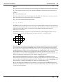
Pass across acquisition lines
In the second pass INTREPID examines each column or row of the located line
structure perpendicular to the acquisition line direction. It notes the values
obtained in the first pass (nodes) and uses them to calculate a spline curve
perpendicular to the acquisition line direction. It uses the spline curve to
calculate values in between the traverse lines. The following diagram illustrates
the process.
3
Box filtering
INTREPID passes through the grid using the Box Filter method (See Initial
gridding—Box Filter) and creates values for any remaining blank cells.
Bi-Cubic Spline parameters
If you are using the Bi-Cubic Spline method, the Gridding Parameters area in the
Command Area looks like this:
Search Radius When interpolating a value for a group of cells during the second
pass of the Bi-Cubic Spline process, INTREPID searches in both directions for
nodes so that it can calculate a spline curve. It requires two nodes on each side of
the cells. This parameter specifies a distance limit for this search. If INTREPID
cannot find the nodes within this distance, it will not interpolate the cells.
Specify the Search Radius (in distance units) in the corresponding text box. We
recommend a Search Radius larger than twice the line spacing, or 10 times the
cell size (The recommended number of cells from one line to the next is 4).
Note: If your dataset is geodetic (latitude and longitude) you need to specify the
Search Radius in degrees.
Nominal Bearing You must set this parameter. See Nominal Bearing for
instructions.
Library | Help | Top
© 2012 Intrepid Geophysics
| Back |
INTREPID User Manual
Library | Help | Top
Old Gridding (T22)
23
| Back |
Rotate Line Data If you are gridding 'oblique' acquisition lines (not oriented North–
South or East–West), you must create a rotated grid aligned with the acquisition
lines. If this is the case, turn on Rotate Line Data. See Producing a rotated grid
for details.
Recording the original data points used
You can save a record of the data points selected for use by this gridding process (the
sample points– selected because they were closest to the cell centroids).
>> To save the sample points used by Bi-Cubic Spline gridding
Assign a value to the system parameter INTREPID_FAST_POINTS before
processing. INTREPID will save the sample points for the process as a point dataset
called fast.
See INTREPID system parameters and install.cfg (R07) for further information
about system parameters in INTREPID.
Initial gridding—Trend Spline
This section is for line dataset gridding only. You can produce grids from line dataset
fields using this method.
Trend spline uses Bi-Cubic Spline gridding but includes a preliminary process which
examines groups of lines together to find directional trends. Using this information
in the gridding process can enhance the appearance of anomalies that lie at oblique
angles to the traverse lines.
Note: We recommend that you only use this method with surveys that have regularly
spaced lines.
The Trend Spline direction finding process involves two basic steps
1
INTREPID examines changes in all directions along groups of lines and calculates
a trend direction for each data point (the direction in which there is the least
change).
2
INTREPID uses this data to create sets of additional data points between the
acquisition lines.
___
After the direction process, INTREPID creates the grid using the Bi-Cubic Spline
method (See Initial gridding—Bi-Cubic Splinee)
For full details of these process see articles by Brindt and Hauska (1985)17 and
Fitzgerald, Yassi and Dart (1997)28.
It is possible to 'tune' Trend Spline gridding to accept or reject solutions based upon
reliability of data in one direction versus another. If this capability is of interest to
you, please contact our technical support service.
1.7 Brindt, L. and Hauska, H., 1985, Direction dependent interpolation of aeromagnetic
data Eleventh International Symposium on Machine Processing of Remotely Sensed Data,
Purdue University, Indiana, USA.
2.8Fitzgerald, D., Yassi, N. and Dart, P., 1997, A case study on geophysical gridding
techniques: INTREPID perspective: Exploration Geophysics, 28, 1–
Library | Help | Top
© 2012 Intrepid Geophysics
| Back |
INTREPID User Manual
Library | Help | Top
Old Gridding (T22)
24
| Back |
Trend spline parameters
If you are using the Trend Spline method, the Gridding Parameters area looks like
this:
Search Radius See Initial gridding—Bi-Cubic Spline for an explanation of this
parameter.
Nominal Bearing See Initial gridding—Bi-Cubic Spline for comments about this
parameter.
Rotate Line Data See Initial gridding—Bi-Cubic Spline for comments about this
parameter.
(Trend Variance Factor) The trend variance factor is the minimum level for
significance of local variations. The number of trend points generated is very
sensitive to the value of this parameter. Its default value is 1 (Z unit) You can
change the value of the trend variance factor if you are using a task specification
file for your gridding process. Edit the task specification (.job) file, changing the
value in the Trend_Variance_Factor = line according to your requirements,
e.g., Trend_Variance_Factor = 2. See Displaying options and using task
specification files for further information.
Process reports for the Trend Spline method
You can inspect a report of the aspect ratio between line spacing and cell size during
the gridding process. Under Unix this appears in the background window. Under
Windows it is written to an ntout report file. See "Diagnostic reporting options" in
Configuring and using INTREPID (R04) for more information.
Recording the additional trend points
You can save a record of the additional data points created between the acquisition
lines (the additional trend points).
>> To save the additional trend points
Assign a value to the system parameter INTREPID_TREND_POINTS before
processing. INTREPID will save the additional trend points as a point dataset called
trend.
See INTREPID system parameters and install.cfg (R07) for further information
about system parameters in INTREPID.
Library | Help | Top
© 2012 Intrepid Geophysics
| Back |
INTREPID User Manual
Library | Help | Top
Old Gridding (T22)
25
| Back |
Initial gridding—Box Filter
You can produce grids from line and point dataset fields using this method. The Box
filter progressively examines each empty cell in the grid in relation to its immediate
neighbours and calculates a value for it based on an average value of its neighbours.
The Box Filter process repeats until all cells have a value or until it has completed
the maximum number of iterations you have specified.
The Box Filter assumes that the original data points are at the cell centroids. It does
not take account of the actual position of data points within the cell (i.e., it has no
'honour original points' process) and therefor may not be as accurate as other
methods.
Box Filter as a finishing process for other methods
If you use Nearest Neighbours or one of the Spline initial gridding methods,
INTREPID uses the Box Filter after the process to fill any remaining gaps in the grid.
Box Filter parameters
If you choose the Box Filter method, the gridding parameters area will appear as
follows.
Box iterations You can use this text box to specify the maximum number of Box
filter iterations you wish INTREPID to perform before moving to the image
refinement stage.
You do not need to specify Box Iterations if Box Filter is operating only as a final
stage of another initial gridding method.
Gridding parameters summary
You can set the general Gridding Parameters in the top right corner of the Command
area.
The various Gridding processes require different selections of these parameters. The
following tables show Gridding parameters that are required for each method.
'Yes' means that you must specify a value.
Blank means that INTREPID does not use or require the parameter in the process at
this stage, although its effect on the data may be carried through from a previous
stage.
'ON' means that the option must be turned on for the process.
Library | Help | Top
© 2012 Intrepid Geophysics
| Back |
INTREPID User Manual
Library | Help | Top
Old Gridding (T22)
26
| Back |
Gridding parameters for line datasets
Process
Grid
Cell
Size
Extrapolate
Cell
Nominal Bearing
Rotate
Line
Data
Search
Radius
Grid initialisation
yes
yes
if required for
acquisition line
identification
Nearest Neighbours
yes
yes
Bi-Cubic Spline
yes
yes
yes
ON*
yes
Trend Spline
yes
yes
yes
ON*
yes
Box Filter
yes
yes
if required for
acquisition line
identification
Box
Iterations
yes
* for 'oblique' line datasets
Gridding parameters for point datasets
Process
Grid Cell Size
Extrapolate Cell
Grid initialisation
yes
yes
Nearest Neighbours
yes
yes
Box Filter
yes
yes
Box Iterations
yes
Image Refinement
After the initial gridding process, INTREPID can perform LaPlace convolution,
Minimum Curvature and Masking image refinement processes.
If you are refining an existing grid, INTREPID can perform LaPlace convolution and
Minimum Curvature Smoothing refinement. The Minimum Curvature process will
not use the honour originals method in this case, since no original data is available.
You can specify the image refinement processes in the Image Refinement area of the
Gridding Main window.
Library | Help | Top
© 2012 Intrepid Geophysics
| Back |
INTREPID User Manual
Library | Help | Top
Old Gridding (T22)
27
| Back |
LaPlace iterations
This is a heavy smoothing convolution filter that INTREPID applies to all initial grid
estimates. It leaves the original points alone. The process improves the condition of
the grid for the Minimum Curvature process. If you perform LaPlace convolution,
Minimum Curvature will require fewer iterations to achieve a satisfactory result.
The LaPlace formula appears below.
Where
Z0 is the value in the cell being processed before the adjustment,
Z01 is the value in the cell being processed after the adjustment,
R is the relaxation factor,
Z1, Z2, Z3, Z4 are the values in the surrounding cells as shown,
Z1
Z2
Z0
Z3
Z4
If Z0 does not contain original data, then
Z1 + Z2 + Z3 + Z4
1
Z 0 = ⎛⎝ -----------------------------------------– Z 0⎞⎠ × R + Z 0
4
Relaxation factor See Minimum Curvature for more information about this
parameter.
Minimum Curvature
The Minimum Curvature method progressively examines each interpolated cell in the
grid in relation to its immediate neighbours and changes its value based on the value
of the neighbours.
The aim of the minimum curvature method is to produce a smooth surface of grid
values. Working in both directions, it adjusts cell values using a second derivative
calculation based on the differences between the values of the adjacent cells. It does
not modify the original data points.
INTREPID uses a relaxation factor to accelerate the interpolation process. As
INTREPID calculates a new value for each interpolated cell, it multiplies the
difference between the old and adjusted value by the relaxation factor. The default
value of the relaxation factor is 1.375.
Library | Help | Top
© 2012 Intrepid Geophysics
| Back |
INTREPID User Manual
Library | Help | Top
Old Gridding (T22)
28
| Back |
Where
Z0 is the value in the cell being processed before the Minimum Curvature adjustment,
ZA is the adjusted value in the cell after the Minimum Curvature process has been
applied,
R is the relaxation factor,
Z1 is the new value in the cell being processed after the minimum curvature process
and relaxation factor adjustment have been applied,
If Z0 does not contain original data, then
Z1 = ( ZA – Z0 ) × R + Z0
INTREPID will repeat the process until it has completed the number of iterations you
specify in the Maximum Iterations text box, or the maximum residual change for all
cells is less than the value you specified in the Maximum Residual text box,
whichever occurs first.
INTREPID normally uses the 12 cells immediately surrounding the target cell as
comparison values in the Minimum Curvature process, as shown below.
The Minimum Curvature process can use an 'honour original data' system if required.
If you choose this method, INTREPID allows for the actual position of the original
data point in an original data cell (rather than the cell centroid) when calculating the
weight (influence) of the cell in an adjustment of a neighbouring cell. If you are using
the Gridding tool to enhance an existing grid, the grid will have no link with its
original data, and therefore INTREPID cannot use any honour originals method. See
below for additional explanation of the honour originals process.
At the end of the Minimum Curvature process, INTREPID can perform several
further passes through the grid where it adjusts original data cells values in the same
way as it has been adjusting interpolated cells. This process is called smoothing, and
has the effect of further smoothing the grid near original data cells.
If you are using the Gridding tool to enhance an existing grid, INTREPID will only
perform the Minimum Curvature process in Smoothing mode, since the original data
can not be distinguished.
Library | Help | Top
© 2012 Intrepid Geophysics
| Back |
INTREPID User Manual
Library | Help | Top
Old Gridding (T22)
29
| Back |
>> To use Minimum Curvature image refinement
1
Turn on the Minimum Curvature check box in the Image Refinement parameters
area. INTREPID displays the Minimum Curvature parameters selection area.
2
Set the Honour Original Data (on or off, number of cells to use), Iterations,
Maximum Residual, Smoothing, Smoothing Iterations according to your
requirements.
Honour Original Data If you turn off Honour Original Data, INTREPID will
assume that the original data points are located at the centroids of all original
data cells, and calculate the same weight (influence) for the cell in all directions.
If you turn on Honour Original Data, INTREPID will allows for the actual
position of the original data point in an original data cell (rather than the cell
centroid) when calculating the weight (influence) of the cell in an adjustment of a
neighbouring cell. This can improve the accuracy of the image refinement
process. An original data point can have up to 128 x 128 different positions in a
cell.
If you are using the Gridding tool to enhance an existing grid, original data is not
available and INTREPID will automatically turn Honour Original Data off.
The Honour Original Data method has two variants: 1 cell and 2 cell. See the
section immediately following for an explanation.
Note: The honour original data process described here uses the same information
but is otherwise independent of the honour original data process used in Nearest
Neighbours initial gridding (See Initial gridding—Nearest Neighbours).
Honour Original Data: 1 or 2 cell Choose the option button according to your
requirements. The default option is 2 cell.
For 1 cell Honour Original Data, INTREPID simply calculates the weight
(influence) of each original data cell on neighbouring cells based on the location of
the original data point rather than the cell centroid, as explained above.
For 2 cell Honour Original Data, for each original data cell, INTREPID
Library | Help | Top
1
Locates the quadrant of the original data cell in which the original data point
lies;
2
Treats the 3 cells surrounding this quadrant as original data cells;
3
Locates the nearest original data points to the respective centroids of the 3
cells;
4
For each of the 3 cells, uses the value of its chosen data point and its position
to calculate the weight (influence) of the cell for adjusting neighbouring cells.
© 2012 Intrepid Geophysics
| Back |
INTREPID User Manual
Library | Help | Top
Old Gridding (T22)
30
| Back |
When
•
Every cell has changed during the last scan by less than the value that you specify
(the maximum residual change), or
•
The maximum iterations have been performed,
the Minimum Curvature process will stop.
Iterations You can use this text input box to specify the maximum number of times
that INTREPID may scan through the grid (number of iterations) during the
Minimum Curvature process.
Maximum Residual Each time INTREPID scans the grid in its attempt to smooth
the grid, it may cause a change in the value of each interpolated cell. As it
completes each progressive scan, the change in each cell becomes smaller—the
interpolated values are becoming 'settled'.
You can use this text box to specify the stage at which you consider that the
interpolated values are sufficiently 'settled' (leaving residual changes to be
ignored).
Specify the Maximum Residual in the same units as your Z data.
If you are gridding magnetic data we recommend a value of 0.1nT to produce the
best print quality.
Smoothing If you turn on Smoothing in the Refinements area, after INTREPID has
completed the Minimum Curvature process, it will perform several further
Minimum Curvature passes through the grid. During these passes it will adjust
original data cell values in the same way as it has been adjusting interpolated cell
values. This has the effect of further smoothing the grid.
Smoothing Iterations Use this text box to specify the number of smoothing
iterations to perform.
(Relaxation factor) See above in this section for an explanation of the function of
the relaxation factor. You can change the value of the relaxation factor if you are
using a task specification (.job) file for your gridding process. Edit the .job file,
changing the value in the Relaxation_Factor = line according to your
requirements, e.g., Relaxation_Factor = 1.325. See Displaying options and
using task specification files for information about batch mode.
Masking
Depending on the density of your original data, the cell size, and the value of the
Extrapolate Cell parameter, INTREPID will fill gaps in the grid during the gridding
process.
You may, on one hand, require a grid with no undefined regions, and require the
Gridding tool to fill all gaps as best it can by interpolation.
Library | Help | Top
© 2012 Intrepid Geophysics
| Back |
INTREPID User Manual
Library | Help | Top
Old Gridding (T22)
31
| Back |
On the other hand, you may
•
Have one or more regions which should not have data at all, and for which
interpolated data would be meaningless, or
•
Require that the grid contain only data that is close to original data points.
In the Masking process, INTREPID sets to null all interpolated cells that are too far
from an original data cell. INTREPID uses the value of the Extrapolate Cell
parameter as the limit for the retaining or removing interpolated cells. For example,
if Extrapolate Cell=2, then it sets to null all interpolated cells that are more than 2
cells away from an original data cell.
Whether you use Masking or not, if the Clipping process is enabled (See (Clipping /
Crew Cut) for details below), INTREPID will sets to null all interpolated19 cells that
are outside the row and column limits.
If you are using the Gridding tool to enhance an existing grid, INTREPID will not
perform the Masking process.
>> To use Masking
Turn on the Masking check box in the Image Refinement parameters area.
The Extrapolate Cell parameter
INTREPID will use this parameter to specify the number of interpolated cells to
retain around an original data cell. For example, if Extrapolate Cell is 3, INTREPID
will mask (set to null) interpolated cells that are not within three cells of an original
data cell. See Cell extrapolation limits for more information about this parameter.
(Clipping / Crew Cut)
The gradients at the edge of a grid can be extremely important in obtaining a good
result from the gridding process. Keeping edge interpolation to a minimum is a
desirable process. The Gridding tool has two processes which limit the number of
interpolated cells at the edges of a grid.
Clipping
In the Clipping process, INTREPID sets to null all interpolated cells20 on the edge of
the grid that are outside the row and column limits.
By default, Clipping is enabled.
If you prefer extrapolated values around the border of the grid that are produced by
Gridding to those produced by the Grid Filter tool (See
Old spectral domain grid filters (OldGridFFT) (T38)
Spectral domain grid filters tool (GridFFT) (T40)
Spectral domain grid filters (GridFFT) wizard (T39)
for details), you may wish to turn off Clipping.
1.9 Strictly speaking, these are extrapolated.
2.0 Strictly speaking these are extrapolated.
Library | Help | Top
© 2012 Intrepid Geophysics
| Back |
INTREPID User Manual
Library | Help | Top
Old Gridding (T22)
32
| Back |
>> To disable Clipping
You must use Gridding in batch mode, and edit the task specification (.job) file
accordingly. To turn Clipping off, edit the Clipping = line so that it reads
Clipping = No. To turn Clipping on, edit the line so that it reads Clipping =
Yes. See Displaying options and using task specification files for information about
batch mode.
Crew Cut
The Crew Cut process is more stringent. If Crew Cut is enabled, both sides of an
interpolated cell must be close to (within the value of the Extrapolate Cell parameter
of) an original data cell, or the cell will be set to null.
By default, Crew Cut is disabled.
>> To enable Crew Cut
You must use Gridding in batch mode, and edit the task specification (.job) file
accordingly. To turn Crew Cut off, edit the CrewCut = line so that it reads
CrewCut = No. To turn Crew Cut on, edit the line so that it reads CrewCut = Yes.
See Displaying options and using task specification files for information about batch
mode.
The Extrapolate Cell parameter
If you disable Clipping, the value of this parameter will show the number of
extrapolated cells retained around the original data cells at the edge of the grid. For
example, if Extrapolate Cell is 3, there will be a border of three interpolated cells
around the outside of the grid. See Cell extrapolation limits for more information
about the Extrapolate Cell parameter.
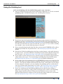
Viewing the gridding progress and clearing the display
You can view the grid as INTREPID creates it.
>> To view the gridding process
1
Turn on Show Gridding in the Display menu
2
Choose the Gridding Main window from the Window menu.
INTREPID displays the progress of the gridding as a pseudocolour image in this
display area. INTREPID represents one grid cell with one pixel up to 600 x 600 cells.
For larger grids it subsamples the data to produce the screen image.
INTREPID automatically and dynamically adjusts the limits of the pseudocolour
scale according to the data that it is representing, so that it uses the full range of the
scale for the data concerned.
If you are working with a large dataset (See Storage of completed grids, memory
limits, large grids, output files), INTREPID will use a tiling algorithm for the grid.
Instead of expanding squares, you will see the image grow in strips)
Library | Help | Top
© 2012 Intrepid Geophysics
| Back |
INTREPID User Manual
Library | Help | Top
Old Gridding (T22)
33
| Back |
>> To clear the display in the Gridding Main window
Choose Clear from the Display menu.
Viewing data in the early gridding stages
To examine your grid in the early stages when you can only see the cells containing
data and possibly their immediate neighbours, choose Box Filter with Box Iterations
set to 1 or some small number, LaPlace Iterations set to 0 and Minimum Curvature
turned off. The process will stop after the number of iterations that you specify.
You can also view the cells containing original data at any time during the gridding
process in the Gridding Original Data window. To view this page, choose Original
Data from the Window menu.
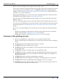
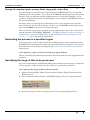
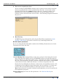
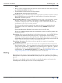
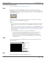
Gridding progress display example—point dataset
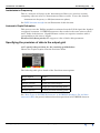
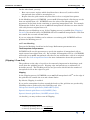
Gridding progress display example—line dataset
Library | Help | Top
© 2012 Intrepid Geophysics
| Back |
INTREPID User Manual
Library | Help | Top
Old Gridding (T22)
34
| Back |
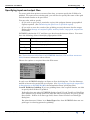
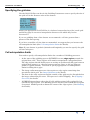
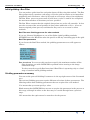
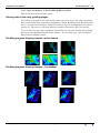
Display example—Bi-Cubic Spline
This illustration shows the progress across the screen of the Bi-Cubic Spline process.
The Gridding Windows
INTREPID can use the Gridding windows to display the
•
Gridding process (in pseudocolour),
•
Original data (in pseudocolour)
•
Gridding specifications and process reports (as text)
•
Tiling control area and reports (as text)
>> To choose the display that you require
Use the Windows menu.
Library | Help | Top
© 2012 Intrepid Geophysics
| Back |
INTREPID User Manual
Library | Help | Top
Old Gridding (T22)
35
| Back |
The Gridding Main Window
To view the Gridding Main window, choose Main from the Window menu.
The Gridding Main window contains
•
A display area for the gridding process
•
The gridding process status display area
•
The Gridding parameters area
•
The Image Refinement parameters area
•
The Apply and Stop buttons
The Gridding Original Data window
After the gridding process commences, the Gridding Original Data window contains a
pseudocolour display of the original data cells.
>> To view the Gridding Original Data window choose Original Data from
the Window menu.
Library | Help | Top
© 2012 Intrepid Geophysics
| Back |
INTREPID User Manual
Library | Help | Top
Old Gridding (T22)
36
| Back |
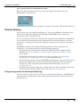
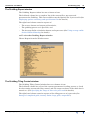
The Gridding Report window
The Gridding Report window has two columns of text.
The left hand column has a complete list of the current files, processes and
parameters for Gridding. This text would become the Options file if you saved it (See
Displaying options and using task specification files for details)
The right hand column contains reports of
•
The source dataset and output grid statistics,
•
The gridding process as it proceeds, and
•
The Average Strike calculation button and report area (See Using average strike
for the Nominal Bearing for details).
>> To view the Gridding Report window
Choose Report from the Window menu.
The Gridding Tiling Control window
The Gridding Tiling Control window has two columns of text.
The left hand column has a list of the current parameters for tiling process, a check
box for turning on manual tiling control, and tile range text boxes if the check box is
turned on. (See Specifying the range of tiles to be processed for details.)
The right hand column contains reports of the tiling process as it proceeds (See
Storage of completed grids, memory limits, large grids, output files).
Library | Help | Top
© 2012 Intrepid Geophysics
| Back |
INTREPID User Manual
Library | Help | Top
Old Gridding (T22)
37
| Back |
>> To view the Gridding Tiling Control window
Choose Tiling Control from the Window menu.
Apply
When you choose Apply INTREPID will carry out the Gridding process that you have
specified.
Gridding status and progress reporting
Status and progress indicators
During each stage of the Gridding process, INTREPID displays progress information
in the Status area at the bottom of the Gridding Main window.
Gridding Report
INTREPID reports information about the dataset and the gridding process, including
•
The numbers of Rows and Columns and
•
The Projection
>> To view the gridding report
Choose Report from the Window menu. INTREPID displays the Report window,
which contains this information in its right half.
Tiling Report
INTREPID reports information about the tiling process,
>> To view the tiling report
Choose Tiling Control from the Window menu. INTREPID displays the Tiling Control
window, which contains the report in its right half.
Library | Help | Top
© 2012 Intrepid Geophysics
| Back |
INTREPID User Manual
Library | Help | Top
Old Gridding (T22)
38
| Back |
Trend Spline process reports
See Process reports for the Trend Spline method.
Stop
If you wish to cancel the Gridding process before it is complete, choose Stop.
INTREPID displays the Abort Gridding confirm dialog box. (With the current release
of INTREPID, you may need to choose Stop several times in order for INTREPID to
display this dialog box.)
Choose Yes to confirm that you wish to stop the process. Choose No to continue
processing from where INTREPID suspended it.
Notes:
•
If you are processing a small grid that fits into memory, all work on the grid will
be lost, except for the initial statistics that INTREPID calculated for the input
dataset.
•
If you are processing a large grid using the tiling process, INTREPID will retain
all tiles that have been completed, but all work on the current tile being processed
will be lost (See Storage of completed grids, memory limits, large grids, output
files for details).
•
If you choose Apply again before you exit from Gridding, then
•
If you are processing a small grid that fits into memory, processing will
commence from the beginning with the current set of parameters;
•
If you are processing a large grid using the tiling process, gridding will
recommence at the start of the tile that INTREPID was processing when
gridding stopped.
Help
You can use the Help menu to display help text on the topics shown in the menu
illustration below.
Exit
To exit from Gridding choose Quit from the File menu.
Library | Help | Top
© 2012 Intrepid Geophysics
| Back |
INTREPID User Manual
Library | Help | Top
Old Gridding (T22)
39
| Back |
Displaying options and using task specification files
Displaying options
To display the current file specifications and parameter settings, choose Report from
the Window menu.
INTREPID displays the Gridding Report window containing the task specifications.
Using task specification files
You can store sets of file specifications and parameter settings for Gridding in task
specification (.job) files.
>> To create a task specification file with the Gridding tool
1
Specify all files and parameters
2
If possible, execute the task (choose Apply) to ensure that it will work.
3
Choose Save Options from the File menu. Specify a task specification file
(INTREPID will add the extension .job) INTREPID will create the file with the
settings current at the time of the Save Options operation.
For full instructions on creating and editing task specification files see INTREPID
task specification (.job) files (R06).
To use a task specification file in an interactive Gridding session
Load the task specification (.job) file (File menu, Load Options), modify any settings
as required, then choose Apply.
>> To use a task specification file for a batch mode Gridding task
Type the command gridding.exe with the switch –batch followed by the name and
path if necessary of the task specification file.
For example, if you had a task specification file called surv329.job you would use
the command
gridding.exe –batch surv329.job
Library | Help | Top
© 2012 Intrepid Geophysics
| Back |
INTREPID User Manual
Library | Help | Top
Old Gridding (T22)
40
| Back |
Task specification file notes and example
Here is an example of a Gridding task specification file
Process Begin
Name = Gridding
XIN = /disk1/survey/ebagoola_S/x
YIN = /disk1/survey/ebagoola_S/y
ZIN = /disk1/survey/ebagoola_S/raw_mag
LineType = /disk1/survey/ebagoola_S/linetype
OutputImage = /disk1/survey/raw_grid2
Parameters Begin
InitialMethod = BiSpline
BoxOption5 = No
Grid_Size = 70.0
Search_Radius = 2000.0
LineOrientation = -999
MinimumCurvature = Yes
ManualTilingControl = No
Honour_Original = Yes
Honour_2Cells = Yes
Cells2Extrapolate = 2
CellsInOverlap = 10
MaximumIterations = 100
CurrentBand = 0
NumberOfBands = 1
MaximumResidual = 2.0
MinimumCurvatureTension = 0.0
Relaxation_Factor = 1.375
Trend_Variance_Factor = 1.0
ZFilter = None
ZPass = Pass
Window = 5
Tolerance = 0.1
Masking = No
Masking2 = No
Clipping = Yes
Smoothing = No
Rotate_Lines = No
SmoothingIterations = 4
LaplaceIterations = 4
StartTile = 1
FinishTile = 1
Parameters End
Process End
Library | Help | Top
© 2012 Intrepid Geophysics
| Back |
INTREPID User Manual
Library | Help | Top
Old Gridding (T22)
41
| Back |
Notes
You can modify the following operations or parameters only by editing a task
specification file:
You can disable the Clipping operation by editing the Clipping = line so that it
reads Clipping = No. To enable Clipping, edit the line so that it reads Clipping =
Yes. See (Clipping / Crew Cut) for details.
•
You can enable the CrewCut option. See (Clipping / Crew Cut) for details.
•
You can modify the relaxation factor in the minimum curvature process (See
Minimum Curvature for details). Change the value in the
Relaxation_Factor = line according to your requirements, e.g.,
Relaxation_Factor = 1.325.
•
You can modify the Trend_Variance_Factor. See Initial gridding—Trend
Spline for details.
Frequently asked questions
Q : Why doesn't Bispline gridding appear to fill the grid properly on a dataset
with angled lines?
Splining only works in the NS or EW direction. It depends on the bearing entered. ie.
if you enter a bearing of 90, it will spline (NS) for lines which have a bearing within
70º–110º (±20º from 90º), or if you enter 0 it will spline EW for lines bearing 340º–20º.
If you enter 45 you will need to select "rotate dataset" or else it will try and spline NS
(as if lines were bearing 90º) and not find many node points, outputting a generally
blank grid.
Q : What should I make the coarse grid Maximum scan distance for variable
density gridding?
The coarse grid search radius (Max scan distance) should default to something very
large in order to effectively scan the entire area.
It is in the same units as the X and Y coordinates.
Q : Can I grid a subsection of an area without having to define a bounding
polygon dataset?
Gridding from INTREPID v3.7 supports a Clip Box with bounding co-ordinates
directly defined in the job file.
Q : I want to grid the tie lines as well as the traverse lines. How do I do that?
Use the Nearest Neighbours option if you want to grid all the lines. If you have a
Linetype field defined, re-number it to 2 for all lines, then grid.
Another way is to comment out the Linetype alias in the .isi file, then grid. The
Nominal Bearing entry will then control what lines get gridded. If you leave it blank
all lines get gridded.
Bi-splining won't grid all the lines because it ignores lines > 22º from the required
nominal bearing.
Q : How can I change the null value in an INTREPID grid?
Edit the grid using the Spreadsheet Editor, and replace the nulls with the new value.
Then edit the grid header file, and change NullCellValue to the new value.
Library | Help | Top
© 2012 Intrepid Geophysics
| Back |