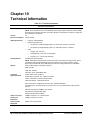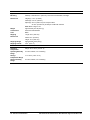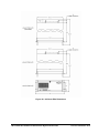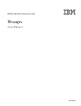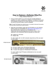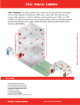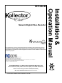
1
XX112-02-00 Network Digital Video Recorder Vicon Industries Inc. does not warrant that the functions contained in this equipment will meet your requirements or that the operation will be entirely error free or perform precisely as described in the documentation. This system has not been designed to be used in life-critical situations and must not be used for this purpose. Copyright © 2004 Vicon Industries Inc. All rights reserved. Product specifications subject to change without notice. ViconNet and its logo are trademarks of Vicon Industries Inc. Kollector Elite, Kollector Pro, VN-306T the Workstation and their logos are trademarks of Vicon Industries Inc. Vicon and its logo are registered trademarks of Vicon Industries Inc. Windows is a trademark of Microsoft Corp. VICON INDUSTRIES INC., 89 ARKAY DRIVE, HAUPPAUGE, NEW YORK 11788 TEL: 631-952-CCTV (2288) FAX: 631-951-CCTV (2288) TOLL FREE: 800-645-9116 24-Hour Technical Support: 800-34-VICON (800-348-4266) UK: 44/(0) 1489-566300 WEB: www.vicon-cctv.com Vicon Part No. 8009-8112-02-00 Section 1 Rev 904 Important Notice This manual is delivered subject to the following conditions and restrictions: •= This manual contains proprietary information belonging to Vicon. Such information is supplied solely for the purpose of assisting explicitly and properly authorized users of the ViconNet system. •= No part of its contents may be used for any other purpose, disclosed to any person or firm or reproduced by any means, electronic or mechanical, without the express prior written permission of Vicon. •= The text and graphics are for the purpose of illustration and reference only. The specifications on which they are based are subject to change without notice. •= The software described in this manual is furnished under a license. The software may be used or copied only in accordance with the terms of that agreement. •= Information in this manual is subject to change without notice. Corporate and individual names and data used in examples herein are fictitious unless otherwise noted. Copyright 2004 Vicon. All rights reserved. ViconNet is a trademark of Vicon. Other company and brand products and service names are trademarks or registered trademarks of their respective holders. XX112-02-00 Rev 904 Kollector Elite Network Digital Video Recorder Important Notice • i About This Manual This Kollector Elite Installation and Operation Manual is comprised of the following chapters: •= Chapter 1, Introduction, introduces the Kollector Elite Video Network Digital Video Recorder. •= Chapter 2, Quick Installation, is for experienced installers, and provides an illustration of how the Kollector Elite should be connected to its various peripherals. •= Chapter 3, Installation, is for novice or first-time installers, and provides step-by-step instruction on how to install the Kollector Elite. •= Chapter 4, Operation, describes how to power on, boot and power off the Kollector Elite. •= Chapter 5, Troubleshooting, provides information on what to do in the unlikely event of a Kollector Elite malfunction. •= Chapter 6, Maintenance, provides information on maintaining the Kollector Elite. •= Chapter 7, Shipping Instructions, describes the procedure to be followed when sending a Kollector Elite back to Vicon. •= Chapter 8, Coaxial Cable Recommendations, provides technical information for the recommended coaxial cable types. •= Chapter 9, Twisted-Pair Cable Recommendations, provides technical information for the recommended twisted-pair cable types. •= Chapter 10, Technical Information, provides the electrical, mechanical and environmental specifications for the Kollector Elite. ii • About This Manual XX112-02-00 Rev 904 Kollector Elite Network Digital Video Recorder Table of Contents CHAPTER 1: INTRODUCTION............................................................................................ 1 How to Use This Manual ............................................................................................................................... 1 For Experienced Installers ........................................................................................................................... 1 For Novice Installers .................................................................................................................................... 2 Accessory Kit ................................................................................................................................................. 2 Unpacking and Inspection ............................................................................................................................ 2 CHAPTER 2: QUICK INSTALLATION ................................................................................ 3 CHAPTER 3: INSTALLATION............................................................................................. 4 About This Chapter........................................................................................................................................ 4 Unpacking the Recorder ............................................................................................................................... 4 Required Items for Installation ..................................................................................................................... 4 Unit Components ........................................................................................................................................... 5 Front Panel Controls and Connections ........................................................................................................ 5 Rear Panel Controls and Connections......................................................................................................... 6 Mounting......................................................................................................................................................... 7 Desktop ........................................................................................................................................................ 7 Rack ............................................................................................................................................................. 7 Installing the Kollector Elite ......................................................................................................................... 8 Step 1: Connecting the Hardware ................................................................................................................ 8 Step 2: Connecting External Hardware to Termination Boxes .................................................................... 9 Step 3: Connecting Looping Cables .......................................................................................................... 11 Step 4: Connecting the Power Supply ....................................................................................................... 12 CHAPTER 4: OPERATION................................................................................................ 13 About This Chapter...................................................................................................................................... 13 Powering On the Recorder ......................................................................................................................... 13 Powering Off the Recorder ......................................................................................................................... 13 CHAPTER 5: TROUBLESHOOTING................................................................................. 14 XX112-02-00 Rev 904 Kollector Elite Network Digital Video Recorder Table of Contents • iii CHAPTER 6: MAINTENANCE........................................................................................... 15 CHAPTER 7: SHIPPING INSTRUCTIONS ........................................................................ 17 CHAPTER 8: COAXIAL CABLE RECOMMENDATIONS ................................................. 18 Materials ....................................................................................................................................................... 18 Cable Types.................................................................................................................................................. 18 CHAPTER 9: TWISTED-PAIR CABLE RECOMMENDATIONS........................................ 20 Materials ....................................................................................................................................................... 20 Cable Types.................................................................................................................................................. 20 CHAPTER 10: TECHNICAL INFORMATION .................................................................... 21 List of Figures Figure 2-1: Kollector Elite Quick Installation ....................................................................................................... 3 Figure 3-1: Front Panel Layout............................................................................................................................ 5 Figure 3-2: Rear Panel Layout ............................................................................................................................ 6 Figure 3-3: Termination Box .............................................................................................................................. 10 Figure 3-4: Resistor Connection Types............................................................................................................. 10 Figure 3-5: Looping Cable ................................................................................................................................. 11 Figure 10-1: Kollector Elite Dimensions ............................................................................................................ 23 List of Tables Table 1-1: Accessory Kit...................................................................................................................................... 2 Table 8-1: Recommended Coaxial Cable Types .............................................................................................. 18 Table 8-2: Picture Quality vs. Cable Length...................................................................................................... 19 Table 9-1: Recommended Individually Shielded, Twisted-Pair Cable Types ................................................... 20 Table 10-1: Technical Information..................................................................................................................... 21 iv • List of Figures XX112-02-00 Rev 904 Kollector Elite Network Digital Video Recorder Chapter 1 Introduction The information in this manual covers the installation and operation of the Kollector Elite Digital Video Recorder. This system should only be installed by a qualified technician using common hand tools and approved materials in accordance with national, state and local wiring codes. The Kollector Elite is an intelligent and rugged Digital Video Recorder. It is a state-of-the-art, Windows-based computer in an attractive industrial steel case. The Kollector Elite is sold in prepackaged configurations with choices of video (frame per second) rates and hard drive sizes, and uses an Intel Pentium CPU platform. All versions run the same Vicon ViconNet software application. For software information, refer to the Kollector Elite Software manual, XX112-3X (where X is a revision number between 0 and 9). Kollector Elite can be networked with all models of Kollector Pro, VN-306T Transmitters and ViconNet workstations to create a complete system. Kollector Elite complies with UL standard 2044, CSA safety standard C22.2, No. 1 and meets requirements for an FCC Class A computing device. Vicon requires the use of line conditioners, voltage regulators and uninterruptible power supply (UPS) systems in the electrical power service. NOTE: Read all instructions before beginning the installation. How to Use This Manual This manual was designed to provide the best overall instructions for the installation and operation of the Kollector Elite Digital Video Recorder. The graphics and terminology used in this manual have been carefully selected to enable a clear and distinct understanding of the Kollector Elite and its configuration. This manual has been formatted to present distinct methods of installation for experienced (strong computer background) and novice installers. For Experienced Installers Refer to Chapter 2, Quick Installation, on page 3. Figure 2-1 presents the most common installation for all ports and connectors of the Kollector Elite. For more detailed descriptions, refer to Chapter 3, Installation and Chapter 4, Operation. XX112-02-00 Rev 904 Kollector Elite Network Digital Video Recorder Introduction • 1 For Novice Installers Complete the remainder of this chapter and then proceed to Chapter 3, Installation. When complete, proceed to Chapter 4, Operation to power-on and boot the system. For software information, refer to the Kollector Elite Software Manual, XX112-3X (where X is a revision number between 0 and 9). Accessory Kit The provided accessory kit contains necessary items needed to install and wire the recorder during installation as follows: Table 1-1: Accessory Kit Part Front Door Key Installation and Operation Manual Software Manual RJ45 Cable Assemblies Description Quantity Opens the front panel door. Provides instructions on installation, configuration and operation. 2 1 1 Connects external devices (sensor input) and communication signals (RS-422 PTZ control). 16 Video Adapter Cable (certain models) Used to adapt the video card ports for various monitors. 1 Optical Mouse Used for GUI operation of the ViconNet software. 1 Looping Cable Provides additional video looping outputs from each camera for use with other video components. 2 Power Cord Used for power connection of Kollector Elite 1 Termination Boxes 16 Unpacking and Inspection All Vicon equipment is tested and inspected before leaving the factory. It is the carrier’s responsibility to provide suitable delivery. Inspect the cartons upon delivery and, if damage is present, make detailed notes on the carrier’s bill. Then, obtain the carrier agent’s signature and file a damage claim as soon as possible. Open the cartons and inspect the equipment for damage. Save the cartons and packing material. If damage is present, contact the carrier and file a damage claim immediately. If the equipment must be returned for repair, follow the instructions in Chapter 7, Shipping Instructions. 2 • Introduction XX112-02-00 Rev 904 Kollector Elite Network Digital Video Recorder Chapter 2 Quick Installation Figure 2-1: Kollector Elite Quick Installation XX112-02-00 Rev 904 Kollector Elite Network Digital Video Recorder Quick Installation • 3 Chapter 3 Installation For novice or first-time installers, these steps provide the most thorough and accurate instructions. About This Chapter This chapter details the complete installation of the Kollector Elite Digital Video Recorder. The following sections provide information as follows: •= Unpacking the Recorder defines how to remove the unit and accessories from the box. •= Required Items for Installation defines items needed for installation. •= Unit Components defines all connections on the front and rear panels and their use. •= Mounting defines all methods of securing the recorder for permanent use. •= Installing the Kollector Elite describes how to install all necessary peripheral devices directly to the recorder, as well as how to install all necessary peripheral devices to the Termination Boxes Unpacking the Recorder Carefully open the carton. Remove the Accessory Kit and the recorder from the box and place them on a large, flat working surface. Open the Accessory Kit and verify the contents against the list in Table 1-1, page 2. Required Items for Installation To properly install the recorder there must be simple hand tools available such as a screwdriver, wrenches, pliers and wire cutters/strippers. To setup the recorder for operation there must be a keyboard available to operate the GUI. 4 • Installation XX112-02-00 Rev 904 Kollector Elite Network Digital Video Recorder Unit Components This section describes the Kollector Elite unit's front and rear panels. Front Panel Controls and Connections The following picture shows the Kollector Elite front panel. Each panel component is described in the table below. Figure 3-1: Front Panel Layout The Kollector Elite's front panel contains the following components: •= Keyboard Port: A USB-type connector used to connect a standard PC keyboard (not included). •= Mouse Port: A USB-type connector used to connect an optical mouse. •= Status LEDs: Used to indicate what the Kollector Elite is doing, for example, scanning for attached cameras or recording. •= Keylock: Used with the provided key to lock the front door. •= Power Switch: Used to power on the recorder (for more details, refer to Powering On the Recorder, page 13). •= LED Indicator: Used to display the power status (ON means recorder on and OFF means recorder off). •= Front Cover: Used to protect the Kollector Elite's front panel from unauthorized use. •= Floppy Drive: Used as a removable data drive. •= CD-RW Drive: Used as a high-capacity removable data drive. XX112-02-00 Rev 904 Kollector Elite Network Digital Video Recorder Installation • 5 Rear Panel Controls and Connections The following picture shows the Kollector Elite rear panel. Each panel component is described below. Figure 3-2: Rear Panel Layout The Kollector Elite's rear panel contains the following components: •= Video Looping Outputs: DB-15 connectors used with provided cables to loop the video inputs out. •= Relay I/O Connections: Not currently used. •= Video (Camera) Inputs: Standard BNC-F connectors used for analog camera video input. •= SMSR (Aux) Connections: Standard RJ-45 connectors used for sensor and communication input for each video channel. SMSR connectors are used for sensors, microphones, speakers and PTZ cameras. •= Power Switch: Used to power on and off the power supply of the recorder. •= Power Receptacle: Used to connect the provided Power Cable. •= Keyboard Port: A mini-DIN type connector used to connect a standard PC keyboard (not included). •= Mouse Port: A mini-DIN type connector used to connect the provided optical mouse. •= Network Port: A standard RJ-45 connector used to connect to a LAN/WAN. •= USB Connectors: Used for optional devices. 6 • Installation XX112-02-00 Rev 904 Kollector Elite Network Digital Video Recorder •= Parallel Port: Used for general printing. •= Serial (COM) Port: Used to connect system serial devices. •= Speaker Output: Mini phono-type connector used for sound card audio output. •= LCD Monitor Output: Used for digital video output to a monitor. A DVI-to-VGA adapter is provided for use with VGA monitors. •= Auxiliary Fan: Used to cool the unit during operation (available on 240 FPS models only). NOTE: Connector locations may vary according to KE type. Mounting There are two types of mounting recommended for the recorder, either desktop or rack. For more details, refer to the Kollector Pre-installation Manual, XX112-7X. Desktop The desk or table must provide a surface of suitable strength for the Kollector Elite’s weight of 45 lb (20.5 kg). In addition, there must be area left around the cabinet to provide suitable airflow for cooling. Do not place heavy items on the cover. Rack The recorder was designed to be mounted in a standard 19-inch (483mm) wide vertical rack. Use the provided rack mount ears to connect the recorder to the rack using hardware provided with the rack. It is recommended that at least ¼ standard rack height of space be left in between multiple recorders mounted in the same rack for cooling purposes. WARNING: Failure to leave space for cooling between recorders may result in malfunctioning and possible failure of the recorder. XX112-02-00 Rev 904 Kollector Elite Network Digital Video Recorder Installation • 7 Installing the Kollector Elite After the recorder is mounted permanently, follow the steps in this section to install the Kollector Elite unit hardware. •= Step 1: Connecting the Hardware, below •= Step 2: Connecting External Hardware to Termination Boxes, page 9 •= Step 3: Connecting Looping Cables, page 11 •= Step 4: Connecting the Power Supply, page 12 IMPORTANT NOTES: The connection of external hardware may require simple hand tools. Do not apply power or plug-in the recorder to any outlet until instructed to do so. Disable the AC power to prevent installer injury and damage to the unit. Before beginning the hardware installation, ensure that the following environmental conditions have been met: •= The surface on which the ViconNet hardware is to be placed must be level. •= The room or area designated for the ViconNet hardware installation must be well ventilated. Step 1: Connecting the Hardware This procedure describes the various hardware connections that must be performed in order to operate the system. To connect the ViconNet hardware: 1. Perform the following connections (refer to Figure 3-1 on page 5 and Figure 3-2 on page 6): •= Locate the keyboard on a flat surface near the recorder. Connect the keyboard by inserting its connector into the correct port. •= Locate the mouse on a flat surface near the recorder. Connect the mouse by inserting its connector into the correct port. •= Position the monitor in a permanent fixed location near the recorder. Connect the monitor by inserting its VGA connector into the VGA Monitor Output port. •= Insert one side of a standard LAN cable to the Network Port’s RJ-45 connector. Insert the other RJ-45 connector into the LAN side of the network. •= Gather and locate all camera video input cables near the rear of the recorder. Insert each BNC-M into its respective Video (Camera) Input port (1 – 16). •= Mount the provided Termination Boxes in a fixed permanent location near the recorder. Insert one end of the provided RJ-45 Cable Assembly into the Termination Box, and insert the other end into the desired SMSR (Aux) Connections port (1 – 16) on the recorder. NOTE: For additional information regarding the devices connected to the SMSR connectors, refer to Step 2: Connecting External Hardware to Termination Boxes, page 9. 8 • Installation XX112-02-00 Rev 904 Kollector Elite Network Digital Video Recorder •= Insert the female end of the provided 120VAC Power Cable into the recorder's Power Receptacle. Do not connect the remaining end to a power receptacle until instructed. If using 230VAC power, it will be necessary to obtain a suitable power cord for use. This cable is a standard computer 230 VAC power cord. •= Turn ON the Power Switch. 2. Connect the monitor to the power source. Step 2: Connecting External Hardware to Termination Boxes The connection of external hardware to the Termination Boxes requires simple hand tools. Do not apply power or plug-in the recorder to any outlet until instructed to do so. WARNING: Disable the AC power to prevent installer injury and damage to the unit. With the Termination Boxes mounted permanently, connect external devices as follows: Communications (PTZ Control) To connect a PTZ camera control to the Kollector Elite: 1. Using a twisted-pair cable as defined in Chapter 9, Twisted-Pair Cable Recommendations, prepare a 4-conductor plus shield type cable by stripping the ends back for use. 2. Connect the PTZ wires to the Termination Box connectors (either TX+ and TX- or RX+ and RX-, depending on the type of the camera (refer to Figure 3-3 on page 10). Ensure that you connect the wires to the correct polarity. 3. Install the other end of this cable into the device it will communicate with, for example, a V1400X-IDL, Camera Dome or other type of receiver. 4. Connect the RJ45 cable to the appropriate channel in the rear panel. Sensor Input When using SMSR connectors to connect devices to the Kollector Elite, refer to the guidelines described below, according to the specific device type. NOTE: Speaker (SPK) will be operational in future versions. To connect a sensor to the Kollector Elite: 1. Using a twisted pair cable as defined in Chapter 9, Twisted-Pair Cable Recommendations, prepare a 2-conductor type cable by stripping the ends back for use. XX112-02-00 Rev 904 Kollector Elite Network Digital Video Recorder Installation • 9 2. Connect the sensor wires to the SENS and GND connectors (refer to Figure 3-3 below). 3. Install the other end of this cable into the appropriate sensor output (NO or NC dry contact). 4. Connect the RJ45 cable to the appropriate channel in the rear panel (refer to Figure 3-2 on page 6). RJ45 Cable Termination Box Figure 3-3: Termination Box 5. When using a detector that operates with a resistor, the resistor should be connected as follows: •= Normally Open Detector: The resistor should be connected to the sensor (SENS) and the ground (GND) connectors. •= Normally Closed Detector: The resistor should be connected between the detector's wire and the ground (GND) connector. NOTE: 16 1KΩ resistors are included. Normally Open Normally Closed Figure 3-4: Resistor Connection Types 10 • Installation XX112-02-00 Rev 904 Kollector Elite Network Digital Video Recorder Step 3: Connecting Looping Cables Looping cables are required only when you wish to retrieve video (output) from the Kollector Elite. The purpose of the cables is to transmit video signals to a second transmitter. Each cable transmits 8 video signals - Looping 1 transmits signals from cameras 1 to 8 and Looping 2 from cameras 9 to 16. To connect the cables: 1. Using the two provided Video Looping Cable Assemblies, insert the large D-type connector end into one of the two Video Looping Output ports. 2. Connect each of the remaining BNC-F connectors to the Video (Camera) Input ports, as defined in the following table. In order to connect the video, male-to-male BNC cables are required (not included). Cable Color Looping 1 Cameras Looping 2 Cameras Red 1 9 Green 2 10 Blue 3 11 Gray 4 12 Black 5 13 Yellow 6 14 White 7 15 Brown 8 16 NOTE: Each BNC cable is labeled for the relevant channel. For example V6680 VIDEO 2/10 (green wire) transmits video from camera 2, if the D type is connected to Looping No. 1, or camera 10 if connected to Looping No. 2. Each channel (wire) is designated a unique color. Eight BNC Connectors D Type Connector Figure 3-5: Looping Cable XX112-02-00 Rev 904 Kollector Elite Network Digital Video Recorder Installation • 11 Step 4: Connecting the Power Supply To ensure that the Kollector Elite is protected during a power failure and that no important data is lost, it must be connected to an uninterruptible power source (UPS) before use. To connect the UPS: 1. Connect the Kollector Elite's power cord to the UPS power receptacle. 2. Connect the UPS power cord to the wall outlet. 3. Power on the UPS and ensure that it is working properly. 4. Power on the Kollector Elite. NOTE: Refer to your UPS device’s User Manual for a more detailed explanation of how to connect it properly. 12 • Installation XX112-02-00 Rev 904 Kollector Elite Network Digital Video Recorder Chapter 4 Operation About This Chapter This chapter details power on, booting and power off of the Kollector Elite Digital Video Recorder. For full programming and operation information, refer to the Kollector Elite Software manual, XX112-3X (where X is a revision number between 0 and 9). The following sections provide information as follows: •= Powering-on the Recorder guides the user through proper power on and boot procedures. •= Powering-off the Recorder guides the user through proper shut down procedures. Powering On the Recorder To power on the system: 1. With the recorder set up as shown in Chapter 3, Installation, verify that the rear panel toggle switch is in the ON position (“I” pressed in). 2. Open the front panel cabinet and press the front panel toggle Power Switch towards the "I" position. The button will switch back to the "O", which is its default position, even when the system is running. IMPORTANT: Do not press any keyboard buttons at this time. When the recorder completes booting and the Main Screen is displayed. For more details, refer to the Kollector Elite Software Manual, XX112-3X. Powering Off the Recorder To power off the system: •= With the recorder booted and operational, press the Shutdown button in the Site Setup window. Follow the screen prompts and the system will return to the ViconNet desktop. Use the Start button to completely shutdown the system. OR (this not recommended, due to the possibility of data loss) Momentarily press the power switch. The system switches off, component by component. XX112-02-00 Rev 904 Kollector Elite Network Digital Video Recorder Operation • 13 Chapter 5 Troubleshooting If the Kollector Elite does not power-up correctly, check the following: •= Verify that the outlet or UPS supplying power is actually active. Plug in a lamp or other device to the outlet to verify the 120 or 230 VAC. If voltage is present, proceed to the next item. •= Verify that the rear panel Power Switch is in the ON position (“I” pressed in). If the recorder fails to boot, proceed to the next item. •= Press the front panel Power Switch so it is in the ON position (“I” pressed in). If the recorder fails to boot, call Vicon Technical Support. •= If the recorder boots, but does not display the Main Screen, reboot the unit by toggling the front panel power switch OFF and ON. If the recorder still fails to boot, call Vicon Technical Support. 14 • Troubleshooting XX112-02-00 Rev 904 Kollector Elite Network Digital Video Recorder Chapter 6 Maintenance Periodic checking and maintenance of certain parts of your Kollector Elite will minimize future system problems. The following table lists the items that need to be checked and when. Maintenance Required Monthly Annually Replacing the filter Cleaning the filter Backing up Checking the front and rear fans To replace the filter: 1. Turn the Kollector Elite off, and then open the front door. 2. Open the filter housing on the left-hand side. 3. Carefully remove the old filter, and then replace it with a new 105mm x 175mm filter. 4. Close the filter housing. 5. Turn the Kollector Elite back on, and then close the front door. To clean the filter: 1. Turn the Kollector Elite off, and then open the front door. 2. Open the filter housing on the left-hand side. 3. Carefully remove the old filter, and then wash it under running water with a mild soap. 4. When the filter is completely dry, return it to its place in the Kollector Elite. 5. Close the filter housing. 6. Turn the Kollector Elite back on, and then close the front door. To back up the Kollector Elite: •= Refer to Chapter 3, Configuring the ViconNet System in the Kollector Elite Software Manual (XX112-3X) NOTE: The backup procedure should be performed whenever a change is made to the system settings. XX112-02-00 Rev 904 Kollector Elite Network Digital Video Recorder Maintenance • 15 To check the front and rear fans: 1. Turn the Kollector Elite off, and then open the front door. 2. Open the filter housing on the left-hand side. 3. Carefully remove the filter, look at the front fan and ensure it is operating properly. 4. Look at the fan in the rear of the Kollector Elite and ensure it is operational. 5. When you have finished, replace the filter, turn the Kollector Elite back on, and then close the front door. CAUTION: Do not open the recorder’s top cover for any reason. Failure to follow this instruction can result in serious injury to the user and void the manufacturer’s warranty. 16 • Maintenance XX112-02-00 Rev 904 Kollector Elite Network Digital Video Recorder Chapter 7 Shipping Instructions Use the following procedure when returning a unit to the factory: 1. Call or write Vicon for a Return Authorization (R.A.) at one of the locations listed below. Record the name of the Vicon employee who issued the R.A. Vicon Industries Inc. 89 Arkay Drive Hauppauge, NY 11788 Phone: 631-952-CCTV (2288); Toll-Free: 1-800-645-9116; Fax: 516-951-CCTV (2288) For service or returns from countries in Europe, contact: Vicon Europe Ltd. Brunel Way Fareham, PO15 5TX United Kingdom Phone: +44 (0) 1489/566300; Fax: +44 (0) 1489/566322 2. Attach a sheet of paper to the unit with the following information: •= Name and address of the company returning the unit •= Name of the Vicon employee who issued the R.A. •= R. A. number •= Brief description of the installation •= Complete description of the problem and circumstances under which it occurs •= Unit’s original date of purchase, if still under warranty 3. Pack the unit carefully. Use the original shipping carton or its equivalent for maximum protection. 4. Mark the R.A. number on the outside of the carton on the shipping label. XX112-02-00 Rev 904 Kollector Elite Network Digital Video Recorder Shipping Instructions • 17 Chapter 8 Coaxial Cable Recommendations CAUTION: Careful selection of proper cable is essential to obtain the best performance from this equipment. Vicon assumes no responsibility for poor performance when cables other than those recommended, or equivalent, are installed. In all cases, coaxial cable impedance should be 75 ohms. Materials Use only a pure copper center conductor. Do not use a copper-plated steel or aluminum center conductor, as they will result in poor quality video. Solid-core bare copper conductor is the best type, where flexing and bending will be minimal. If severe bending and flexing is required for installation, use a stranded center conductor. Never exceed the manufacturer’s minimum bend radius specification. Use cellular (foam) polyethylene dielectric except where heavy moisture exists. For moisture conditions, use solid polyethylene dielectric cable with a heavy exterior insulation. The shield must be copper braid providing 95% or better coverage. Cable Types The cable types listed below are the most common 75-ohm types used. They vary in size (diameter), dielectric type and net DC resistance. The larger cable results in a lower DC resistance and better video quality, with increased difficulty in handling and installation. Let the required picture quality and cable distance provide a guide in choosing the best cable type. For cables other than the approved Vicon types below, contact the manufacturers listed below. Note that “BC” refers to bare copper and “TC” refers to tinned copper. Table 8-1: Recommended Coaxial Cable Types Cable Type Belden Type No. Alpha Type No. West Penn Type No. Type Center Conductor Type Shield and % Coverage DC Resistance ohms/1000 ft (km) RG-11/U 8213 9847 811,4811 14 Solid BC BC braid (95%) 2.6 (8.5) RG-6/U 9248 9804C 806,4806 18 Solid BC Foil + 61% TC braid (100%) 7.5 (24.6) RG-59/U 8281* ---- 815 20 Solid BC 2 TC braids (96%) 9.9 (32.5) RG-59/U 9259 9803 816 22 Stranded BC BC braid (95%) 15.0 (49) RG-59/U 9659 ---- ---- 22 Stranded BC BC braid (95%) 15.0 (49) *Requires special BNC-M connector due to 0.305 nominal O.D. Belden Inc. http://www.belden.com/ (800) 235-3361 Alpha Wire Company http://www.alphawire.com/ (800)-52 ALPHA (522-5742) West Penn Wire http://www.westpenn-cdt.com/ (800)-245-4964 18 • Coaxial Cable Recommendations XX112-02-00 Rev 904 Kollector Elite Network Digital Video Recorder Table 8-2: Picture Quality vs. Cable Length Picture Quality Maximum Cable Run** ft (m) RG-59/U RG-6/U RG-11/U Usable picture 1100 (350) 1500 (450) 2400 (750) Clean picture 820 (250) 1000 (300) 1600 (500) Best picture 400 (120) 530 (160) 820 (250) ** For longer cable runs, use a Vicon Video Amplifier to obtain a suitable picture. XX112-02-00 Rev 904 Kollector Elite Network Digital Video Recorder Coaxial Cable Recommendations • 19 Chapter 9 Twisted-Pair Cable Recommendations CAUTION: Careful selection of the proper cable is essential to obtain the best performance from this equipment. Vicon assumes no responsibility for poor performance when cables other than those recommended are installed. Materials Use a pure copper stranded conductor with or without a tin plating to obtain a low DC resistance. Do not use cable with either a steel or an aluminum stranded conductor because these do not transfer signals effectively for long distances. The preferred insulation and cable jacket is Polyvinyl chloride (PVC). It has better electrical characteristics than polyethylene and resists flames, sunlight and most solvents, but is more vulnerable to moisture. Cable Types The most commonly used cable types are dual individually shielded, twisted pair in a single jacket. This configuration is the most convenient for RS-422/ RS485 applications. Single twisted pair is also a suitable cable. Choose a Belden cable type by referring to the characteristics and maximum distances listed below. The maximum distance for the most reliable digital control refers to the distance between the CPU/Keypad and the Camera Dome Assembly. The characteristics of the cables in Table 6 should be used as a guideline when cables other than Belden are used. Materials and construction must follow the guidelines above. Table 9-1: Recommended Individually Shielded, Twisted-Pair Cable Types Cable Type Wire Size (AWG) Insulation Material Jacket Material Max. Distance ft. (m) Number of Twisted Pairs Belden 9406 22 PVC PVC 5000 (1500) 2 Belden 9402 20 PVC PVC 5000 (1500) 2 Belden 8723 22 Polypropylene PVC 8000 (2400) 2 Belden 8162 24 Datalene 1 PVC 15000 (4600) 2 Datalene 1 PVC 15000 (4600) 2 Datalene 1 PVC 25000 (7600) 1 Belden 9729 Belden 9182 24 22 ¹ Datalene is a Registered Trademark of Belden. 20 • Twisted-Pair Cable Recommendations XX112-02-00 Rev 904 Kollector Elite Network Digital Video Recorder Chapter 10 Technical Information Table 10-1: Technical Information Electrical Characteristics Input Voltage 120 - 230 VAC ±10%, 50/60 Hz nominal. NOTE: Vicon requires the use of uninterruptible power supply systems (UPS) to prevent voltage fluctuations that can affect operation and cause damage to the equipment. Failure to comply with this violates the unit warranty. Current 3A Power Consumption 450 W nominal UPS Requirements •= Capacity: 1000 VA/600 W •= Maximum operation time: •= Heat Equivalent •= 16 cameras recording/displaying with a 15" Sony CRT monitor): 18 minutes •= 16 cameras recording/displaying with a 17" Mag CRT monitor): 5 minutes Input: •= Voltage: 100 - 240 VAC •= Voltage Range: ±30% (with a 4-step AVR) •= Frequency: 47 – 63 Hz (auto detection) 25.6 BTU/min (6.4 kg-cal/min) NOTE: These figures represent the conversion of 100% of the electrical energy to heat. Actual percentage of the heat generated will be less and will vary from product to product. These figures are provided as an aid in determining the extent of cooling required for an installation. System CPU: Intel® Pentium IV 2.66 MHz, minimum RAM: 512 MB HDD: 200 - 900 GB LAN Card: 3Com 10/100 Mbps TPO Connector Types/Quantities Analog Video Inputs: 16 BNC-F Analog Video Loopouts: 16 in 1 DB-15 connector Power: 1 standard 3-conductor female socket VGA Video Output: 1 standard VGA port Sensor Input Port: 16 NO/NC RJ-45 connectors, software selectable PTZ Control Port: 16 individual RJ-45 connections or one 4-pin terminal block using RS-422 protocol Network Port: Ethernet 100Base-T RJ-45 jack Keyboard Port: Mini-DIN jack (PS2) Mouse Port: Mini-DIN jack (PS2) Video Level Input All BNC connectors: 1.0 V peak-to-peak Video Input Impedance All BNC connectors: 75 ohms Video Formats Supported NTSC, PAL, EIA and CCIR XX112-02-00 Rev 904 Kollector Elite Network Digital Video Recorder Technical Information • 21 Mechanical Characteristics Application Indoor Mounting Desktop or standard 19 in. (483 mm) rack mount and stackable, 4U height Dimensions Height (H): 7.0 in. (178 mm) Width (W): 19.0 in. (483 mm) Depth (D): 22.0 in. (558.8 mm) for 120 fps models 24.25 in (615.95 mm) for 240 fps models with extra fan Note: Refer to Figure 10-1. Weight Approximately 45.0 lb (20.5 kg) Construction Steel case and hardware Color Black Shipping Dimensions Length: 25 in. (635 mm) Width: 24 in. (610 mm) Height: 12 in. (305 mm) Shipping Weight Approximately 53 lb (24 kg) Shipping Volume 4.2 ft (0.12 m ) 3 3 Environmental Characteristics Operating Temperature Range: 32 to 104° F (0 to 40° C) Operating Humidity Range 0 to 95% relative, non-condensing Storage Temperature Range -4 to 158° F (-20 to 70° C) Storage Humidity Range 0 to 95% relative, non-condensing 22 • Technical Information XX112-02-00 Rev 904 Kollector Elite Network Digital Video Recorder Figure 10-1: Kollector Elite Dimensions XX112-02-00 Rev 904 Kollector Elite Network Digital Video Recorder Technical Information • 23 Vicon Industries Inc. Corporate Headquarters 89 Arkay Drive Hauppauge, New York 11788 631-952-CCTV (2288)/ 800-645-9116 Fax: 631-951-CCTV (2288) Vicon Europe Headquarters Brunel Way Fareham, PO15 5TX United Kingdom +44 (0) 1489 566300 Fax: +44 (0) 1489 566322 Brussels Office Planet II - Unit E Leuvensesteenweg 542 B-1930 Zaventem Belgium +32 (2) 712 8780 Fax: +32 (2) 712 8781 Far East Office Unit 5, 17/F, Metropole Square 2 On Yiu Street, Shatin New Territories, Hong Kong (852) 2145-7118 Fax: (852) 2145-7117 Internet Address: www.vicon-cctv.com