1
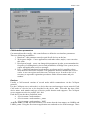
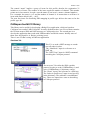
October 1999
BridgeView CANopen server User Guide
Filimonov V.M. PNPI
This Server ensures a link between devices on a CAN bus and the BridgeVIEW system. The
devices must implement the CANopen protocol. CANopen is defined in the form of
documents describing profiles. There are the several device profiles. The server supports two
CANopen device profiles:
DS-401 CANopen Device Profile for I/O Modules The CANopen devices from WAGO is a
example of such modules,
DS-404 CANopen Device Profile for Measuring Device and Closed-Loop Controller. LMB
belongs to this profile.
The server works with National Instruments CAN-PCI board.
The CANopen server is implemented as a standard BridgeVIEW device server. In order to
work with any device server it is necessary to execute several actions:
1. Register server,
2. Configure Tags using TAG configuration editor, (see BridgeVIEW User Manual)
3. Developing application. The standard VI library in BridgeVIEW has a set of Vis for
reading and writing Tags. Additionally, in the end of the documents is the description of
the small library that can help to work with the CANopen devises and LMB.
Register Server
In order to fulfill the first step there is a special VI “Register CanOpen Server.vi”. A user
should fills out the controls on the panel according to
a CAN bus configuration and
then launch this VI. If the VI finishes without any message it is mean that the registration
process has executed correctly.
The front panel of this VI is shown on “Fig 1”.
There are four types of configuration parameters:
1. Server parameters. They define a name of a server and a place from what the
BridgeVIEW system launches it.
2. CAN interface parameters,
3. Devices, for the server each node is a device.
4. Data items, Each device can connect with several sensor and actuators. It is a data
item. A data item has the several attributes: name, type, and direction. Additionally,
It is necessary to define how server can extract data or put them in CAN message. It
is depended on the device profile. Therefor there are two controls for device profile
401 and 404.
Server parameters
1. Server Name - this is a name for the registration in BridgeView system. A user
can choose any name. This name is used in Configuration tags editor.
2.
Server VI name – this parameter defines the Server Vi and path to him relative of
registration VI. The Usually such the server place as the registration is the same
place.
1
October 1999
CAN Interface parameters
Can network interface config – this control allows to define the can interface parameters.
There are following possibilities:
1. Baud rate – this parameter must be equal for all devices on the bus.
2. Write queue length – if user applications send rather often, maybe, a user can arise
this value.
3. Read queue length – a user can change this parameters in order to accommodate the
frequency of sending data by device and possibilities of BridgeView system (server,
engine and application) receives messages.
4. Port – a National Instrument board can have two buses and it is possible to have
more then one board on a computer. This parameter defines with what bus a server
works. A user can register more then one CANopen server. In order to do it, it is
necessary to repeat the registration procedures with a deferent name and port
number.
Devices
Usually a CAN network consists of several nodes which communicate via the CANopen
protocol.
For the CANopen server each node is a device that can send messages across network. Each
CAN node or a device has to be described in the device table. This table has three field;
device name, node number and type of device profile that the node supports. The CANopen
server supports two device profiles: 401, 404.
Each device has the three predefined items
• <Device name><node number>
• <Device name><node number>_status
• <Device name><node number>_NMT
A device name is LMB and node number is 26 means that the item names are LMB26 and
LMB26_status. Using the first item an application can send and receive SDO massages. There
2
October 1999
are two subVIs, which realize the expedited protocol. It is allowed to read/write a dictionary
entry in CANopen devices via CANopen server.
The second one is a status device item that contains an error code as described in CANopen
specification. The error codes are taken from “Emergency massage “ that nodes send and the
CANopen server reads, periodically. The dictionary entry with index 1001 and subindex 0
that must contains an error code.
The third TAG is to sent NMT message to a node.
Additionally, there is a special device named “CANbus”. (Fig. 3) The device can be used for
control all CAN network. The device has three items: NMT, SYNC and SYNC Interval.
A user can connect a tag with this item and use it in an application for controlling the whole
CAN network by sending NMT message. The SYNC and SYNC interval items can be used
to send SYNC massage. The first of them is used for sending a single SYNC message. In
order to send SYNC message periodically, it is needed to write into the tag connected to
SYNC interval items the number of seconds and the CANopen server start, to send SYNC
massage at that interval.
Data items
Real-time data for the monitoring and control of devices are usually transferred by PDO
messages. There are two tables describing the mapping of items to a PDO message for 401
and 404 device profile.
Profile 401
According to device profile 401 for digital and analogue input and output modules one PDO
message can contain data of different types.
The first table describes the PDO mapping and contains following items:
1. Name – this name can be used to create tag.
2. Direction – there are three possibilities for this item: output, input, in/out.
3. Data Type – this item can have following values:
• BOOL – Boolean, (1 bit),
• I8 – signed byte,
• I16 – signed short integer (two bytes),
• I32 – signed integer (four bytes),
• U8 – unsigned byte,
• U16 – unsigned short integer (two bytes),
• U32 – unsigned integer (four bytes),
• SGN – single flout (four byte),
• DBL – double flout (8 bytes),
• BTA – bit array, a length is defined in the “Length” item. The maximum length is
64 bit.
Device name – this is a name of device that item belongs. This device must describe in device
table and this device must have the 401-profile type.
PDO number – this is a identification of CAN message.
Byte number – the first byte from 8 byte CAN message where this item is.
Bit number – this item is used only for BOOL and BTA data types. It points out number of bit
in byte from previous item.
Length - this item is used only for BTA data type. It determines the length of bit array.
Profile 404
In the device profile 404 for measuring and closed-loop controllers, a PDO message contains
one item of data and a special byte that is the channel number.
3
October 1999
The control “name” implies a group of items for this profile, therefor the registration Vi
includes a set of items. The number of the items equals the number of channel. This number
points out in last controls. In such a case the name of one item is <name><channel number>.
For a example, the name is “rd” and the number of channel is 16 means that we will have 16
items with names rd0,rd1,rd2,…,rd15.
The next four items for describing PDO mapping in profile type 404 are the same as for the
profile type 401.
CANopen toolkit VI library
This library can be useful for developing a BridgeView application, which are based on
CANopen server and a LMB CAN node. It can be divided on three sets. First of them contains
the VIs that ensures SDO and NMT message to CANopen devices. The second part is to
develop the application that works with LMB modules and Pt100 sensors. Initially most of
them were developed be A. Karlov (coloring icons).
There is one VI that is using in LMB test application.
Services VIs
This Vi is to send a NMT message to a node
or to all nodes in a bus.
The “NumNode” input is a reference to a
NMT tag.
The “NMT Com” input is a NMT command
according the CANopen protocol.
The next two VIs realize the SDO expedite
protocol in order to read (CORDictEntry.vi) and
write (CORDictEntry.vi) dictionary entries.
The “Name” input is the reference to a SDO tag.
The “Index in profile area” input is two-byte key
in the dictionary. The subindex is an additional
key. These two inputs have sense as describing
in CANopen protocol.
4
October 1999
LMB and Pt100 VIs
The “LMB ADC Pack.vi” is to pack the ADC
setting in one byte to write in LMB.
The “LMB ADC Unpack.vi” unpacks a byte for
representing the ADC setting. For more information
look at LMB profile.
The” SetLMBMode.vi” is to switch a mode of LMB.
LMB has sync and acync modes.
This Vi saves the flash memory of LMB because in
the beginning it checks the current mode.
The “LMB RT Raw Conversion.vi” transforms data
taken from LMB ADC node using Trend Tag.vi. If
“Raw? Input is false data are converted to real to
real voltage. On the output this Vi puts Trend data
(raw or real voltage), array of configuration bytes
and array of status bytes.
The next two Vi is to use for converting data from
Pt100 module
The LMB_R-T.vi is to transform data
using calibration constants.
The “trend data input” is raw data taken
from Trend Tag.vi.
“CH” is a Boolean array that permits to
select LMB channels.
“Unit” is a Boolean if it is True
Data are converted in Celsius.
5
October 1999
Otherwise It are converted in Kelvin.
The “Predestal” is an array of data taken when the
inputs of ADC are shortcuts (default zero).
The “Rbase” is an array of values the input registers
(default 30om).
The last input (Calibration coefficients) is twodimension array of polonium calibration data. (Default
empty)
The “LMB ADC to Temperature.vi executes the same
conversion only for one Pt100 sensors.
Miscellanies
The “Select Tag List.vi” is a serve that
allows selecting Tags from a list of tags.
6