1
HARDWARE
Clamps
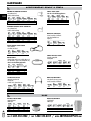
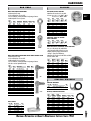
Miniature Clamps
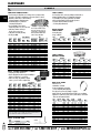
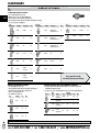
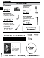
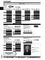
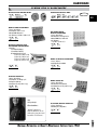
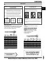
Slotted Hex Head Hose Clamps
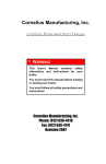
•Lightweight, streamlined clamp is generally used in small diameter applications such
as air and fuel lines.
•Streamlined design allows for installation in tight fitting or difficult to reach areas.
•Creates high sealing pressure with 10 to 15 inches per pound of installation torque.
•Stainless steel band with plated hex screw.
•5/16" band width.
25
25
25
25
25
25
10
10
10
10
10
10
10
10
10
10
10
10
10
10
10
10
10
LA
72450
72451
72452
72453
72454
72455
72456
72457
72458
72459
72460
72461
72462
72463
72464
72465
72466
72467
72468
72469
72471
72472
4
6
8
10
12
16
20
24
28
32
36
40
44
48
52
56
60
64
72
80
96
104
7/32
7/16
1/2
9/16
11/16
13/16
13/16
1-1/16
1-5/16
1-9/16
1-13/16
2-1/16
2-5/16
2-9/16
2-13/16
3-1/16
3-5/16
3-9/16
1-7/8
2-1/2
3-5/8
4-1/8
5/16
5/16
1/2
1/2
1/2
1/2
1/2
1/2
1/2
1/2
1/2
1/2
1/2
1/2
1/2
1/2
1/2
1/2
1/2
1/2
1/2
1/2
25
25
25
25
25
25
25
10
10
10
10
10
10
10
10
10
10
10
5
5
5
5
A
5/8
25/32
29/32
1-1/16
1-1/4
1-1/2
1-3/4
2"
2-1/4
2-1/2
2-3/4
3"
3-1/4
3-1/2
3-3/4
4"
4-1/4
4-1/2
5"
5-1/2
6-1/2
7"
V
RT M
SO
AI
BL
E
Qty.
AS
Band
Width
T
EN
Effective Range
Min.
Max.
Diameter Diameter
7/32
7/16
1/2
9/16
11/16
15/16
1-3/16
1-7/16
25
25
25
25
25
25
25
25
5/8
25/32
15/16
1-1/16
1-1/4
1-1/2
1-3/4
2"
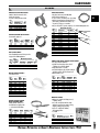
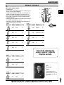
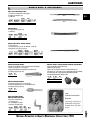
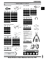
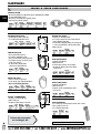
•Specifically designed to prevent damage to silicone rubber
hose and other soft hoses under tightening loads, while
providing full sealing efficiency.
•A worm drive clamp is combined with a
stainless steel liner, preventing both extrusion and shearing through the band notches.
•Stainless steel band with plated hex screw.
•9/16" band width, except Part No. 72337 is 1/2".
•High corrosion-resistant stainless steel clamps necessary for marine, underground and other high corrosion applications.
•Band and house 300 series stainless steel.
•305 stainless steel screw.
Size
No.
4
6
8
10
12
16
20
24
Lined Hose Clamps
All Stainless Steel Hose Clamps
Part
No.
Qty.
72314
72299
72380
72381
72382
72383
72384
72385
LA
#81
#320-1
Part
No.
Size
No.
Effective Range
Min.
Max.
Dia.
Dia.
72329
72330
72331
72332
72333
72334
72335
72336
72337
72338
72339
6
8
10
12
16
20
24
28
32
36
40
7/16
1/2
9/16
11/16
13/16
13/16
1-3/16
1-5/16
1-9/16
1-13/16
2-1/16
25/32
29/32
1-1/16
1-1/4
1-1/2
1-3/4
2"
2-1/4
2-1/2
2-3/4
3"
V
RT M
SO
AI
#86
#79
LAB
L
Qty.
Part
No.
Size
No.
Effective Range
Min.
Max.
Dia.
Dia.
Qty.
25
25
25
25
25
25
25
25
25
25
10
72340
72341
72342
72343
72345
72344
72346
72347
72348
72350
72349
44
48
52
56
60
64
72
80
88
96
104
2-5/16
2-9/16
2-13/16
3-1/16
3-5/16
3-9/16
4-1/8
4-5/8
5-1/8
5-5/8
6-1/8
10
10
10
10
10
10
10
10
10
10
10
3-1/4
3-1/2
3-3/4
4"
4-1/4
4-1/2
5"
5-1/2
6"
6-1/2
7"
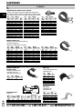
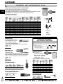
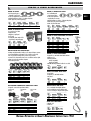
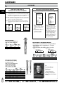
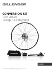
Hi-Torque hose clamps
•Guaranteed to withstand more than three times the SAE standard torque
requirements for worm drive clamps.
•All 304 stainless steel band and housing with 410 stainless screw.
•5/8" wide band.
Part
No.
Effective Range
Min.
Max.
Diameter Diameter
Qty.
72321
72322
72323
72352
1-1/4
2-1/8
4"
6-1/8
10
10
10
5
2-5/8
4-1/8
6-1/8
9-1/2
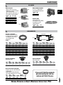
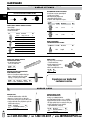
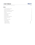
HOse clamp driver with flex shaft
•Flexible shaft allows for 90° access.
•Reversible socket fits both 1/4" and 5/16" hex heads.
•Socket fits mini and standard hose clamp screw heads.
•No-slip grip.
Part
No.
Qty.
72360
1
B1
E
1/2
1/2
1/2
1/2
1/2
1/2
1/2
1/2
1/2
1/2
1/2
1/2
1/2
1/2
1/2
1/2
1/2
1/2
1/2
1/2
1/2
1/2
1/2
#85
#78
BL
Effective Range
Min.
Max.
Diameter Diameter
AS
25/32
29/32
1-1/16
1-1/4
1-1/2
1-3/4
2"
2-1/4
2-1/2
2-3/4
3"
3-1/4
3-1/2
3-3/4
4"
4-1/4
4-1/2
5"
5-1/2
6-1/2
7"
8-1/2
12-1/4
AI
E
7/16
1/2
9/16
11/16
13/16
13/16
1-1/16
1-5/16
1-9/16
1-13/16
2-1/16
2-5/16
2-9/16
2-13/16
3-1/16
3-5/16
3-9/16
1-7/8
2-1/2
3-5/8
4-1/8
5-5/8
9-3/8
V
Size
No.
T
EN
6
8
10
12
16
20
24
28
32
36
40
44
48
52
56
60
64
72
80
96
104
128
188
Qty.
Part
No.
A
72478
72300
72301
72302
72303
72304
72305
72306
72307
72308
72309
72310
72311
72312
72313
72315
72316
72317
72318
72319
72324
72397
72399
Band
Width
RT M
SO
T
EN
Size
No.
A
Part
No.
Effective Range
Min.
Max.
Diameter Diameter
AS
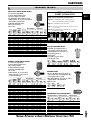
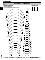
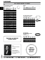
•Exceeds SAE requirements.
•Heavy duty four-piece, Quadra-lok construction.
•Band made of grade 300 series stainless steel.
•Controlled electronic welding of housing to band provides extra strength.
•Shouldered 5/16" slotted hex head screw is made of carbon steel, which is double-plated for excellent corrosion resistance.
•For large hose sizes, assemble clamps in tandem to obtain required size.
Personal Customer Service / Same Day Shipping / No Risk Guarantee
HARDWARE
Clamps
Constant Torque Clamps
Clamp Diameter
Part
No.
Cross
Ref.
Band
Width
Min.
72370
72371
72372
72373
72374
72362
72363
72375
72376
72377
72378
72379
72364
72392
72393
72367
72368
72369
CT9410
CT9412
CT9416
CT9420
CT9424
CT9428
CT9452
CT175L
CT200L
CT250L
CT300L
CT350L
CT400L
CT450L
CT500L
CT550L
CT600L
CT650L
9/16
9/16
9/16
9/16
9/16
9/16
9/16
5/8
5/8
5/8
5/8
5/8
5/8
5/8
5/8
5/8
5/8
5/8
9/16
11/16
13/16
13/16
1-1/16
1-5/16
3-3/4
1"
1-1/4
1-3/4
2-1/4
2-3/4
3-1/4
3-3/4
4-1/4
4-3/4
5-1/4
5-3/4
Max.
Installation
Torque Max.
(A)
Screw Tip
Extension
Qty.
1-1/16
1-1/4
1-1/2
1-3/4
2"
2-1/4
2-13/16
1-3/4
2-1/8
2-5/8
3-1/8
3-5/8
4-1/8
4-5/8
5-1/8
5-5/8
6-1/8
6-5/8
30 - 70 inch lb
30 - 70 inch lb
30 - 70 inch lb
30 - 70 inch lb
30 - 70 inch lb
30 - 70 inch lb
30 - 70 inch lb
50 - 125 inch lb
50 - 125 inch lb
50 - 125 inch lb
50 - 125 inch lb
50 - 125 inch lb
50 - 125 inch lb
50 - 125 inch lb
50 - 125 inch lb
50 - 100 inch lb
50 - 100 inch lb
50 - 125 inch lb
3/16
3/16
3/16
3/16
3/16
3/16
3/16
1/4
1/4
1/4
1/4
1/4
1/4
1/4
1/4
1/4
1/4
1/4
5
5
5
5
5
5
5
5
5
5
5
5
5
5
5
5
5
5
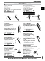
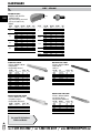
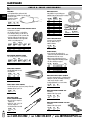
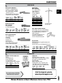
Gates® shrink PowerGrip™ clamps
Cross
Ref.
Gates
No.
72815
72819
72822
72825
72829
72834
72841
72848
72854
72860
72867
72873
72879
72886
72890
SB15
SB19
SB22
SB25
SB29
SB34
SB41
SB48
SB54
SB60
SB67
SB73
SB79
SB86
SB90
32915
32919
32922
32925
32929
32934
32941
32948
32954
32960
32967
32973
32979
32986
32990
1/4
3/8
1/2
5/8
3/4
1"
1-1/4
1-1/2
1-3/4
2"
2-1/4
2-1/2
2-3/4
3"
3-1/8
RT M
SO
T
EN
Part
No.
Nominal
Hose I.D.
AI
1/2
11/16
13/16
15/16
1-1/16
1-3/16
1-1/2
1-3/4
2"
2-1/4
2-1/2
2-3/4
3"
3-1/4
3-1/2
5
5
5
5
5
5
5
5
5
5
5
5
5
5
5
Note: To ensure correct clamp selection, measure the hose
outer diameter with hose installed on stem.
Part
No.
Description
Qty.
72814
Heavy-Duty Removal Tool
1
call
1-800-558-2808 /
#72814
fax
A
Spring-Loaded
T-Bolt Clamps
•Heavy-duty spring.
•Torque to 60 in-Ib.
Part
No.
Diameter
Min.
Max.
Qty.
74368
74371
74375
74361
74372
3-1/16
3-1/8
3-9/16
3-11/16
3-7/8
5
5
5
5
5
3-3/8
3-7/16
3-7/8
4"
4-3/16
Part
No.
Diameter
Min.
Max.
74391
4-1/16
74369★ 4-1/16
74373
4-1/8
74376
4-9/16
74374
6-3/8
★ Small Spring
4-3/8
4-3/8
4-7/16
4-7/8
6-11/16
Qty.
5
5
5
5
5
T-Bolt Clamps
Without Spring
Part
No.
Diameter
Min.
Max.
Qty.
Part
No.
Diameter
Min.
Max.
Qty.
74362
74363
74364
74365
74366
74377
74378
74379
74380
74370
1-1/4
1-1/2
2"
2-1/4
2-5/8
2-1/2
2-3/4
3"
3-1/4
3-7/16
5
5
5
5
5
5
5
5
5
5
74367
74381
74389
74382
74383
74384
74385
74386
74388
74390
3-1/2
3-3/4
4"
4-1/4
4-3/4
5-1/4
5-3/4
6-1/4
7-1/4
8-1/2
5
5
5
5
5
5
5
5
5
5
1-25/64
1-11/16
2-5/16
2-9/16
2-15/16
2-13/16
3-1/16
3-5/16
3-9/16
3-3/4
3-13/16
4-1/16
4-5/16
4-9/16
5-1/16
5-9/16
6-1/16
6-3/4
7-3/4
9"
#88
Euro Style Clamp
Pkg
Qty.
Gates® SB clamp tool
•For heavy-duty vehicle, construction, military and commercial use.
•Diameter adjustment range is 5/16" minimum to maximum.
•1/4–28 UNF x 2-3/4" long steel plated bolts are standard.
•Carbon steel plated washer and hex nut with nylon insert.
•3/4" wide x .025" thick 300 series stainless steel heavy-duty band material.
L
LAB
Hose Outside
Diameter
Min.
Max.
11/16
13/16
15/16
1-1/16
1-3/16
1-1/2
1-3/4
2"
2-1/4
2-1/2
2-3/4
3"
3-1/4
3-1/2
3-5/8
T-Bolt Clamps
E
V
A
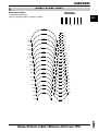
•PowerGrip™ SB clamps "shrink to fit."
•Ideal for all applications, with unsurpassed sealability on
all types of coolant hoses—even silicone.
•Unlike other clamps, they maintain a dynamic tension so you never need to re-tighten them.
AS
B2
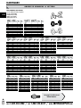
•A revolutionary new clamp that reacts to changes in hose systems by actually
increasing or decreasing its own diameter as the system expands or contracts.
•Eliminates coolant loss due to cold flow leakage, and greatly minimizes clamp maintenance.
•Automatically adjusts to operational or environmental temperatures.
•Used on all radiator, silicone heater, and air charged after-cooler hose connections.
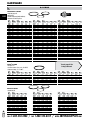
The "CT" clamp is installed correctly as
•Each clamp contains a visual torque shown above, when the screw tip "A"
check to ensure proper torque.
("Torque Check") is extended beyond
•Solid stainless steel clamp assembly.
the housing and the belleville washer
stacks are nearly collapsed flat.
•Used by most OEMs.
•Plated hex screw.
•430 Stainless steel bands.
•Features an "Outrigger" support that prevents clamp tilting when tightening.
•No edge pressure prevents hose damage or gouging.
•Band is embossed, smoothed off and has raised edges to prevent damage.
•Applications: coolant lines, fuel lines, oil lines, water and hose connections in
automotive and commercial vehicles
Part
No.
Industry
No.
Band
Width
Hex
Screw
Clamp
Range
Clamp
Range
Qty.
73681
73682
73683
73684
73685
73686
73687
73688
73689
73690
73691
73692
73693
73694
1
2
2
4
8
12
18
18
24
30
36
42
48
56
7.5mm
7.5mm
9mm
9mm
9mm
9mm
9mm
9mm
9mm
9mm
9mm
9mm
9mm
9mm
6mm
6mm
7mm
7mm
7mm
7mm
7mm
7mm
7mm
7mm
7mm
7mm
7mm
7mm
5/16 - 1/2
5/16 - 5/8
5/16 - 5/8
1/2 - 3/4
5/8 - 11/16
3/4 - 1-1/4
1 - 1-5/8
1.181 - 1.574
1-1/4 - 2"
1-5/8 - 2-3/8
2" - 2-3/4
2-3/8 - 3-1/8
2-3/4 - 3-1/2
3-1/8 - 4"
8 - 12mm
8 - 16mm
8 - 16mm
12 - 20mm
16 - 27mm
20 - 32mm
25 - 40mm
30 - 45mm
32 - 50mm
40 - 60mm
50 - 70mm
60 - 80mm
70 - 90mm
80 - 100mm
25
25
25
25
25
25
25
25
25
25
25
25
25
25
1-800-553-8769 /
www.IMPERIALSUPPLIES.com
HARDWARE
Clamps
CONSTANT TENSION CLAMP
Two-ear clamps
•Made of SAE 1074 - material code ST.
•Finish: Zinc-rich paint
•Conforms to SAE specification J1508.
Part
No.
Clamp Range
Qty.
69966
69967
69968
69969
25.2mm to 28.9mm
23.5mm to 26.8mm
27.0mm to 31.5mm
31.5mm to 38.0mm
50
50
50
50
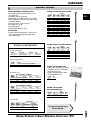
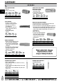
•Zinc-plated, carbon steel, SAE 1008/1010.
•Ideal for heavy vibration areas.
•To be used on low or medium pressure hose/tubing.
•Works great in applications requiring rubber hose, plastic tubing, coaxial and electrical cable, rope, shop air hose, fluid, gas, or steam lines.
•One piece design offers a positive, tamper proof seal without damaging the hose.
Spring Action Hose Clamp
•Heat treated, spring steel.
Part
No.
Hose
Outside
Diameter
Width
Maximum
Diameter
Qty.
72361
72365
72366
5/8
1/2
3/4
5/16
5/16
5/16
0.583
0.460
0.645
100
100
100
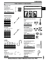
Fuel Line Clamps
•Fits all standard automotive fuel injection hose.
•Approved for all OEM applications.
Part
No.
Hose
Outside
Diameter
Clamp Range
Clamp Range
Qty.
72490
72491
72492
1/4
5/16
3/8
13/32–31/64
7/16–39/64
15/32–41/64
10-13 mm
12.5-15.5 mm
13.5-16.5 mm
20
20
20
Maximum Hose Diameter
75060
75068
75061
75062
75063
75064
75064-4
75065
75066
75066-4
I.D.
Qty.
1/4
3/16
5/16
3/8
1/2
5/8
5/8
3/4
1"
1"
3/8
1/2
1/2
1/2
1/2
1/2
1/2
1/2
1/2
1/2
50
50
50
50
50
25
250
25
25
250
Qty.
69972
69973
69974
69975
69976
69977
69979
69980
69982
69983
69984
69986
69989
69992
69993
.118-.197"
.197-.276"
.276-.354"
.315-.433"
.433-.512"
.512-.591"
.591-709"
.669-.787"
.787-.906"
.866-.984"
.906-1.063"
1.457-1.575"
1.693-1.811"
Pincer = standard jaw
Pincer = side jaw
25
25
25
25
25
25
25
25
25
25
25
25
25
1
1
.197"
.236"
.276"
.276"
.276"
.295"
.315"
.335"
.354"
.394"
.394"
.394"
.394"
•Fast, simple and safe installation.
•Specially formed strip edges reduce the risk of damage to the part being clamped.
•Tampering is visible - Low profile.
•Curled insert bridges the gap below the clamp ear and thus provides an effective all around seal.
•Material: Stainless steel
•Use with #10 screw.
Band
Width
Maximum Hose Diameter
Clamp Range
Band Width
Single Ear Crimp Clamp With Insert
Nylon cable clamps
Part
No.
Part
No.
Part
No.
Size
Band
Width
Clamp Range Qty.
70534
70535
70536
70537
70539
70540
70542
70544
M7
M8
M9
M10
M7.4
M8.2
M8.2
M8.2
6.4 mm
6.4 mm
7.4 mm
7.4 mm
12.3 mm
13.8 mm
15.5 mm
17.5 mm
5.6-6.5 mm
6.3-7.5 mm
7.0-8.5 mm
8.0-9.5 mm
9.8-11.8 mm
11.1-13.1 mm
12.8-14.8 mm
14.6-16.8 mm
25
25
25
25
25
25
25
25
Make-a-clamp®
•Make any size stainless steel clamp you need,
2" diameter and up.
•Use for all conventional worm-drive clamp
applications as well as for mounting, securing,
strapping, clamping and positioning.
•Superior to "crimp/buckle" banding and strapping products.
•1/2" band.
CENTER PUNCH CLAMP
And Locking Tool
•Clamp material: Stainless steel
•Portable hand tool applies punch to 3/8" and 5/8" band clamps.
Part
No.
Diameter
Width
Thickness
Qty.
72353
72354
72355
72356
72357
72358
72351
13/16
1-1/2
2-1/2
3"
4"
5"
Tool
3/8
5/8
5/8
5/8
5/8
5/8
—
.020
.022
.022
.022
.022
.022
—
10
10
5
5
5
5
1
#72351
Part
No.
Description
Qty.
72325
72326
72327
72328
Kit: (50') Band, (10) fasteners
Fasteners
(100') Band
(50') Band
1
10
1
1
National Distributor of Quality Maintenance Supplies Since 1958
#69992
#69993
B3
HARDWARE
Clamps
Clamp
Size
Mounting
Hole
Qty.
Part
No.
Clamp
Size
Mounting
Hole
Qty.
75075
75075-2
75076
75076-2
75078
75078-2
75079
75079-2
75039
75039-2
75040
75040-2
75041
75041-2
1/4
1/4
5/16
5/16
3/8
3/8
1/2
1/2
3/16
3/16
1/4
1/4
5/16
5/16
1/4
1/4
1/4
1/4
1/4
1/4
1/4
1/4
3/8
3/8
3/8
3/8
3/8
3/8
100
25
100
25
100
25
50
10
100
25
100
25
100
25
75042
75042-2
75043
75043-2
75044
75044-2
75086
75045
75045-2
75046
75046-2
75047
75047-2
75049
3/8
3/8
1/2
1/2
5/8
5/8
5/8
3/4
3/4
7/8
7/8
1"
1"
1-1/4
3/8
3/8
3/8
3/8
3/8
3/8
1/2
3/8
3/8
3/8
3/8
3/8
3/8
3/8
100
25
50
10
25
10
25
25
5
25
5
25
5
25
AS
RT M
SO
T
EN
Part
No.
V
A
B4
•Coating of 1/32" glossy black vinyl fused to zinc-plated metal in permanent bond.
•The coating prevents abrasion and provides excellent resistance to chemical action from
water, detergents, gasoline, oil, grease, strong alkalies, acids and many other substances.
AI
#120-1
L
LAB
E
Rubberized tube clamps (VINYL COATED)
Part
No.
Clamp
Size
Mounting
Hole
Qty.
75049-2
75080
75080-2
75038
75088
75081
75081-2
75048
75087-2
75056
75085
75090
1-1/4
1-1/2
1-1/2
1-3/4
2"
2"
2"
1/2
2"
2-1/4
2-1/2
3"
3/8
3/8
3/8
13/32
9/32
3/8
3/8
17/32
17/32
13/32
13/32
13/32
5
25
5
25
25
25
5
25
5
10
20
5
Rubber Cushion CLIP
•Thick rubber cushion reduces vibration and cable wear.
•Metal band is galvanized steel.
•Multiple uses for holding cable, wire, pipe and hose.
Part
No.
Clamp
Diameter
Mounting
Hole Size
Qty.
Part
No.
Clamp
Diameter
Mounting
Hole Size
Qty.
74820
74821
74822
74823
74824
74846
74825
74847
74826
74848
1/4
5/16
3/8
1/2
5/8
5/8
3/4
3/4
7/8
7/8
1/4
1/4
1/4
1/4
1/4
3/8
1/4
3/8
1/4
3/8
25
25
25
25
25
25
25
25
25
25
74827
74845
74841
74828
74837
74842
74829
74843
74844
74830
1"
1"
1-1/8
1-1/4
1-3/8
1-3/8
1-1/2
1-3/4
1-7/8
2"
1/4
3/8
3/8
1/4
1/4
3/8
1/4
3/8
3/8
1/4
25
25
25
25
20
25
25
25
25
25
RUBBER CUSHION CLIP
FOR TWO TUBES
Part
No.
Clamp
Diameter
Mounting
Hole Size
Qty.
74839
74838
74834
74831
74833
74832
74836
74835
2-1/4
2-3/8
2-3/8
2-1/2
2-1/2
2-15/16
3"
3-9/16
1/4
1/4
1/4
1/4
13/32
1/4
1/4
9/16
20
20
20
25
20
15
20
5
Half Clips
•Zinc plated with black vinyl coating.
•Mounting Hole: .281"
•Clip holds two 3/4" diameter tubes.
•Zinc-plated, low carbon steel.
•Thick rubber cushion protects tubes.
Part
No.
Clamp
Size
Mounting
Hole Size
Qty.
74840
3/4
13/32
10
Part
No.
Clamp
Diameter
Qty.
75165
75166
75167
75168
75169
75170
75171
3/16
1/4
5/16
3/8
1/2
5/8
3/4
25
25
25
25
25
25
25
A
W
JIFFY CLIPS
C
•Mounting Hole: .281"
•HD Galvanized Steel.
B
Wire frame CLIPS
Overall Length
•Spring steel.
Part
No.
A
(Radius)
Overall
Length
B
C
Width
Metal Thickness
Min.
Max.
Qty.
75058
75059-1
75059
1/4
3/8
3/8
1-1/16
1-9/16
1-5/8
.703
.890
.937
3/16
7/32
1/4
1/2
1/2
1/2
0.074
0.175
0.120
100
100
100
call
1-800-558-2808 /
fax
0.156
0.312
0.175
Part
No.
Width
Clamp
Size
Qty.
75050
75051
75052
75053
75054
75055
1/2
1/2
5/8
5/8
5/8
5/8
1/4
5/16
3/8
1/2
5/8
3/4
100
100
100
50
25
25
1-800-553-8769 /
www.IMPERIALSUPPLIES.com
HARDWARE
Clamps
BEAM FLANGE FASTENER
kwik stik clips
•No holes to drill, no screws to fasten.
•Holds firmly on wood, plastic, metal, plaster, and other similar materials.
•Elastic enough to insert cable, wire hose, etc.
•For permanent or temporary installation.
Part No.
Size
Style
Qty.
75072
75073
75074
75082
75083
75084
75094
1/4
3/8
1/2
1/4
3/8
1/2
1/2
U
U
U
C
C
C
L
50
50
50
50
50
50
50
Style U
•For 1/8" to 1/4" flange thickness.
•Zinc plated and dichromate finished.
Part No.
Qty.
37011
37011-4
25
100
B5
Style C
Hanger iron
•Can be nailed or bolted.
•Non-cutting edge for safer handling.
•Fast application, 3/4" wide.
•20 gauge plated steel.
Style L
Part No.
Size
Qty.
71450
50' roll
1
Grommets
Fire Wall Grommets
Outside Diameter
Inside Diameter
•Rounded corner-type rubber grommets.
•Fire wall grommets mount securely to the fire wall and lock on to the wire that passes through the bushing.
•55 durometer.
•Buna-N.
Groove
Thickness
Groove Diameter
Part
No.
Inside
Diameter
Groove
Groove
Diameter
Outside
Diameter
Thickness
Qty.
Part
No.
Inside
Diameter
Groove
Groove
Diameter
Outside
Diameter
Thickness
Qty.
9070
9071
9072
9073
9090
9074
9091
9075
9076
9082
9077
1/8
3/16
1/4
5/16
3/8
3/8
3/8
7/16
1/2
1/2
5/8
1/16
1/16
1/32
1/16
1/16
3/32
1/4
1/16
3/32
1/4
1/8
3/16
3/16
5/16
1/2
1/2
1/2
1/2
9/16
3/4
13/16
7/8
11/32
1/2
1/2
5/8
5/8
13/16
3/4
3/4
1"
1-1/16
1-1/8
3/16
1/4
3/16
1/4
1/4
3/8
1/2
1/4
9/32
1/2
3/8
25
25
25
25
25
25
25
25
25
25
25
9083
9078
9088
9089
9079
9084
9080
9081
9085
9087
9086
11/16
3/4
3/4
3/4
7/8
7/8
1"
1-1/4
1-1/2
1-1/2
2-1/8
1/8
3/32
1/8
1/4
1/16
1/8
3/32
1/8
1/8
1/4
1/8
1"
15/16
1-1/16
1-1/16
1-1/4
1-1/4
1-3/8
1-1/2
1-3/4
1-3/4
2-1/2
1-5/16
1-1/8
1-3/8
1-3/8
1-5/8
1-5/8
1-3/4
1-7/8
2-1/8
2-1/8
2-7/8
7/16
5/16
7/16
9/16
7/16
1/2
3/8
13/32
1/2
5/8
7/16
25
25
25
25
25
25
25
25
25
25
25
BLANKING GROMMET
WIRING GROMMET
•Black rubber grommet.
•Black rubber grommet.
Part
No.
Slot
Outer
Diameter
Slot
Height
Stem
Diameter
Stem
Height
Base
Diameter
Height
Qty.
9095
.312
.094
.437
.140
.625
.359
25
Part
No.
Overall
Height
Overall
Diameter
Stem
Diameter
Stem
Height
Bore
Diameter
Qty.
9094
.687
1.062
.562
.437
.390
25
Nylon insulating bushing
•Designed to protect wires, cables and tubing from
rough panel edges.
•Employs multiple lock features that snap into place on panels, ranging from 1/32" to 1/8" thick.
Part
No.
Inside
Diameter
Head
Diameter
Thickness
Panel Hole
Diameter
Qty.
70197
70200
49/64
1-5/16
1-1/8
1-39/64
9/16
29/64
1
1-1/2
100
100
If you can't find the products
you are looking for, call us,
and we will find it for you.
National Distributor of Quality Maintenance Supplies Since 1958
HARDWARE
SubheG
ad
rea
r sn
e afm
i tet ignogess h e r e
Part No.
Description
Qty.
72100
Straight
72101
1/4–28
Taper Thread
Description
Qty.
50
72103
Straight/Short
Overall Length: 9/16"
50
45°
50
72104
Straight/Long
Overall Length: 21/32"
50
72102
90°
50
72117
Straight/Extra Long
Overall Length: 15/16"
50
72107
67-1/2°
50
72106
90°
50
72108
30°
50
72122
90° Long
50
72110
Straight x 1-3/4 Long
25
72105
45°
50
72111
Straight x 1-1/4 Long
25
•Use with hand grease guns only.
•Flat top with dirt cutting edge bites through dirt and old grease.
•"Armor-hard" for scratch resistance and longer life.
•Not for use with pneumatic tools.
•Use installation tool #72118.
Part No.
Size
Qty.
72113
3/16
25
72114
72115
1/4
5/16
1/4
Pipe Thread
AI
#171-1
L
LAB
Part No.
Description
Qty.
72119
Straight
10
72120
67-1/2°
10
See pages B7 and B8
72119
for Heavy Duty Grease Fittings.
Drive Style Grease Fittings
Style
AS
Part No.
RT M
SO
T
EN
1/8
Pipe Thread
V
A
B6
•For use with hand grease guns only.
•Wider selection of sizes for multiple applications.
•"Armor-hard" for scratch resistance and longer life.
•Flat top with dirt cutting edge bites through dirt and old grease instantly.
•For use in low pressure applications.
E
Standard Grease Fittings
Grease fittings with self-forming threads
•Specially formed hardened threads allow fittings to be screwed into a plain hole
eliminating the tapping operation.
•To replace, just screw out old fitting and screw in new one with a standard thread.
Style
Part
No.
72531
72536
Thread
1/4-28
Special Taper
1/8-27
Special Taper
Style
Nominal
Hole Size*
Hex
Qty.
Straight
.236
5/16
25
Straight
.375
7/16
25
72532
1/4-28
Special Taper
45°
.236
3/8
25
72533
1/4-28
Special Taper
90°
.236
3/8
25
25
* Actual hole size will depend on the nature of the material.
25
Note: Pictures of Grease Fittings are not actual size.
call
1-800-558-2808 /
fax
1-800-553-8769 /
www.IMPERIALSUPPLIES.com
HARDWARE
G REASE f i t t i n g s
Heavy-Duty Grease Fittings
Qty.
1/4–28
Taper Thread
7.
Part No.
Description
Qty.
A
V
1/4 Pipe
Thread
72100-3
Straight
50
72103-3
Straight/Short
50
72101-3
45°
50
72104-3
Straight/ 11/16" Long
50
72102-3
90°
50
72105-3
45°
50
72107-3
67-1/2°
50
72106-3
90°
50
72108-3
30°
50
RT M
SO
AI
#169-1
BL
E
Description
6.
3.
AS
Part No.
B7
5.
2.
T
EN
1/8 Pipe
Thread
4.
1.
1. Instant identification.
2. Greater convenience—better seal design of tip gives more working angle, up to 35°.
No ridges; coupler won’t slip off in tight quarters.
3. Longer life—all Imperial fittings are "armor-hard", so they last longer and resist
nicks and scratches. No distortion under high pressure, always a perfect seal.
4. Cleaner—flat top with dirt-cutting edge bites through dirt and old grease instantly.
5. Greater strength—extra thick wall construction gives unequalled strength and
withstands hard field service.
6. Faster lubricant flow—finest quality music wire spring has special conical design for
free flow. Will not clog with sudden surge of pressure.
7. Greater safety—exclusive electro-crimping process secures ball and spring with
hardened, extra heavy crimp. No cracks or failures.
LA
Cut costs by reducing your
vendors. Imperial's Specialty
Programs can help.
Part No.
Description
Qty.
72119-3
Pipe Thread
10
72120-3
67-1/2°
10
Justin
Pricing Analyst
Driven…
5/16–24
UNF Thread
Part No.
Description
Qty.
72535
Straight
25
“I understand downtime. I
understand what it costs. And
I do everything I possibly can
to prevent it.”
National Distributor of Quality Maintenance Supplies Since 1958
HARDWARE
SubheG
ad
rea
r sn
e afm
i tet ignogess h e r e
Actual Size diameters
B8
6 mm
8 mm
10 mm
Buttonhead Grease Fittings
•Provides utmost resistance against high and
low back-pressure leakage.
•Ball cavity and spring design provide
maximum dirt and chip clearance.
•Designed to deliver a high volume of grease.
1/8 Pipe
Thread
Part No.
Description
Qty.
72116
1/8" x 27
25
72123
1/4" NPT
25
Heavy-Duty Metric Grease Fittings
•Resists leakage.
•Fast sealing tapered threads.
•Instant release shoulder.
Style
Part No.
Description
Qty.
14600-3
Straight, 6 mm x 1.0P
25
14604-3
Straight, 8 mm x 1.0P
25
14606-3
Straight, 10 mm x 1.0P
25
14610-3
45°, 6 mm x 1.0P
25
14614-3
45°, 8 mm x 1.0P
25
14616-3
45°, 10 mm x 1.0P
25
14620-3
90°, 6 mm x 1.0P
25
14624-3
90°, 8 mm x 1.0P
25
14626-3
90°, 10 mm x 1.0P
25
Qty.
2
Part No.
14631
Description
Straight
Qty.
10
•Caps snap securely over the fitting to seal out dirt and moisture.
•Integral retaining ring keeps the cap in place during service.
•Works on most brake bleeder screws.
•Use with Drive Fittings, Part No. 72113, 72114 and 72115.
Part No.
1/8 NPT Style
Grease Caps
DRIVE TYPE GREASE FITTING
INSTALLATION TOOL
72118
Female Threaded
Standard grease fitting
Grease fittings installation
and removal TOOL
Part No.
Qty.
1060
50
•All-in-one tool installs new straight and angle-type
fittings, re-threads holes and removes straight,
angle-type, or old pin-type broken fittings.
Part No.
Size
Description
Removes
Qty.
72598
72599
Small
Large
1/4"-28 threads
1/8 NPT threads
5/16 & 3/8
7/16
1
1
Experience our dedicated
customer service.
Grease guns
Grease gun
•Can fill with standard cartridges or bulk filled.
•Outputs 5.2 oz (150 g) of grease per 100 strokes.
•Contoured lever: Develops more pressure with less effort
•Complete with hardened four-jaw hydraulic coupler with
ball check and non-drip cap.
Part No.
Description
Qty.
72566
Grease Gun with 6" (150 mm)
Extension Pipe
1
call
1-800-558-2808 /
fax
Professional lever
action grease gun
•Develops up to 10,000 psi (690 bar).
•Can fill with standard cartridges, suction, or bulk filled.
•Equipped with air bleeder valve to vent air pockets and filler nipple with ball check for use with grease filler pump.
•Complete with hardened four-jaw, hydraulic
coupler with ball check, non-drip cap.
Part No.
Description
Qty.
72561
Grease Gun 6" (150 mm)
Extension Pipe
1
1-800-553-8769 /
www.IMPERIALSUPPLIES.com
HARDWARE
Subhead
Gerre ansaemG
e ug
no
ses here
Pistol grip grease gun
•Four-jaw coupler.
•One piece, zinc die-cast body.
•Working Pressure: 6,000 psi
•Uses standard 14 oz cartridge, or use the filler nipple for loading from bulk supply.
Part No.
Description
Qty.
72502
72562
Pistol Grip Grease Gun
12" flex hose
1
1
High pressure grease gun
•For use with high pressure grease systems (7,125 psi).
•Solid steel and aluminum handle.
•Press trigger to obtain continuous grease flow.
•Grease inlet accepts 1/4" NPTM thread.
Part No.
Description
Qty.
72530
72538
72513
72539
Swivel 1/4 NPT (M) x 1/2-27 (M)
No Swivel
Swivel 1/4 NPT (F) x 1/8 NPT (M)
Swivel 1/4 NPT (F) x 1/4 NPT (M)
1
1
1
1
#72538
#72530
MINI PISTOL GRIP GREASE GUN
•Compact and lightweight.
•Pistol grip for easy, one-handed operation.
•Perfect for hard to reach jobs.
•Heavy-duty special LuCast™ cast alloy head.
•Can fill with standard cartridges or bulk fill.
•Outputs 1.5 oz (43 g) of grease per 100 strokes.
•Contoured lever develops more pressure with less effort.
•Ergonomically designed T-handle provides positive grip.
•Non-drip seal on grease coupler to prevent leakage.
•Extension Pipe: 4"
Part No.
72515
6637
Description
Grease Gun with 4" extension
pipe and 3 oz Cartridge
3 oz Lithium Grease Cartridge
Qty.
1
3
PROFESSIONAL pistol grip grease gun
•Heavy-duty cast aluminum pump head.
•Three-way loading: bulk, filler nipple, or cartridge.
•Four-jaw super grip coupler for better grip and extended service life.
•Variable stroke allows the user to increase the pressure output on demand.
Part No.
Description
Qty.
72526
Grease Gun with 12" Flexible
Extension Pipe
1
Grease gun WITH 18" Flex HOSE
•Develops up to 7,000 psi (480 Bar).
•Equipped with air bleeder valve to release trapped air.
•Filler nipple with ball check for use with grease filler pump.
•Complete with hardened four-jaw, hydraulic couplers with ball check and non-drip cap.
•Extension Pipe: 4" (100 mm)
Part No.
Description
Qty.
72542
Grease Gun with 18" Flex Hose
and 4" Extension Pipe
1
Air operated grease gun
•Output 3.5 oz of grease per 100 strokes.
•Can fill with standard cartridge, suction, bulk fill.
•1/4" NPT inlet, 1/8" NPT outlet.
•Working air pressure is 60–90 psi.
•Maximum operating pressure is 3,000 psi.
•Equipped with air bleeder valve to release trapped air.
•Includes filler nipple with ball check for use with grease
filler pump.
•Complete with four-jaw hydraulic coupler, non-drip cap,
and 6" extension pipe.
Part No.
Description
Qty.
72564
1/4" NPT inlet, 1/8" NPT outlet
1
CORDLESS GREASE GUN
Grease Pump Bearing Packer
•Quick connect feature makes different grease transfer jobs, such as filling grease
guns or packing bearings, fast and easy.
•Designed for 35 lb pails.
•Includes universal grease gun filler nipple Part No.
72553, to fit all grease gun models.
•Bearing packer holds bearings up to 6" in diameter and includes dust cover.
Part No.
Description
Qty.
72563
Grease Pump Bearing Packer
1
•The strongest of any gun available, powered by an 18-volt battery.
•Heavy-duty motor delivers over 7,500 psi.
•Ergonomically balanced to minimize operator strain.
•Kit includes:
(1) heavy-duty plastic storage case (2) 18-volt rechargeable NiCad batteries (1) One-hour charger, 42" flexible hose (1) coupler with durable bend restrictors
(1) carrying strap (1) easy-to-follow user manual
Part No.
Description
Qty.
72537
Cordless Grease Gun
1
National Distributor of Quality Maintenance Supplies Since 1958
B9
HARDWARE
Grease Couplers
buttonhead Coupler
Grease fitting
B10
90° COUPLER Grease fitting
•Spring-loaded sleeve locks coupler in place for angular application.
•Complete with small and large quick-
disconnect adapters to fit standard couplers.
•Maximum operating pressure: 4,500 psi
•Zinc plated.
•Use with buttonhead grease fittings.
•Screws on grease gun hose.
Part No.
Female
Inlet
Qty.
72509
1/8 NPT
1
HEAVY-DUTY 360° SWIVEL
Coupler GREASE FITTING
•Swivels in a full 360° circle and locks in place.
•45° angle gives easy access to most grease fittings.
•Includes a standard grease coupler and 1/8" NPT female inlet for easy assembly to standard grease guns.
•For use with air-operated grease guns.
Part No.
Working
Pressure
Female
Inlet
Qty.
72549
6,000 psi
1/8 NPT
1
Female
Inlet
Qty.
72518
4,500
1/8 NPT
1
Qty.
72565
3,000 psi
1
•Designed to lock at any angle up to 180°.
•Spring-loaded sleeve locks coupler in place for straight
applications or slides back for angular application.
•Corrosion-resistant finish.
•For hand-operated grease guns only.
• Male inlet.
•Swivels in a full 360° circle and locks in place.
•45° angle gives easy access to most grease fittings.
•Includes a standard grease coupler and 1/8" female inlet for easy assembly to standard grease guns.
•For hand grease gun use only.
Working
Pressure
Working
Pressure
180° Swivel Grease Coupler
360° SWIVEL Coupler GREASE FITTING
Part No.
Part No.
Part No.
Overall
Length
Working
Pressure
Qty.
72510
4"
3,000 psi
1
Imperial continuously
adds new products.
GREASE COUPLERS
Part No.
Applications
Rating
Thread
Size
Jaw
Ball
Check
Diameter
Length
Hex
Qty.
72505
72514
72506
72608
72508
72609
Hand only
Air/Battery/Hand
Air/Battery/Hand
Air/Battery/Hand
Air/Battery/Hand
Air/Battery/Hand
4,500 psi
5,000 psi
5,000 psi
6,000 psi
8,000 psi
10,000 psi
1/8 NPT
1/8 NPT
1/8 NPT
1/8 NPT
1/8 NPT
1/8 NPT
4
4
4
4
3
4
Yes
No
Yes
Yes
Yes
No
.590
.593
.593
.562
.634
.589
1.5
1.5
1.5
1.5
1.92
1.5
n/a
5/8
5/8
1/2
11/16
N/A
2
2
2
2
2
2
Melanie
Customer Service
Empowered…
“I’m personally responsible
for getting the right part out
the door. If it doesn’t get
done right, it’s on me.”
call
1-800-558-2808 /
fax
1-800-553-8769 /
#72505 & #72514
#72608 & #72609
#72506 & #72508
Experience
our dedicated
customer
service.
www.IMPERIALSUPPLIES.com
HARDWARE
G r e a s e h o s e & Acc e s s o r i e s
HIGH PRESSURE green HOSE
•12" flexible hose assembly with or without adapter.
•Use with air-operated grease gun.
•1/8" NPT end.
#72511
Part No.
Description
Working
Pressure
Burst
Pressure
Qty.
72511
72512
With Adapter
Without Adapter
5,000 psi
5,000 psi
20,000 psi
20,000 psi
1
1
#72512
Grease hose
•For hand-operated grease guns only.
•1/8" NPT end.
Part No.
Length
Working
Pressure
Qty.
72503
72504
12"
18"
4,500 psi
4,500 psi
1
1
Grease Hose with Spring Guard
•3/16" neoprene hose.
•1/8" NPT heavy-duty brass male thread fittings on both ends.
•Spring guard for secure grip on coupler end.
Part No.
Length
Maximum
Working
Pressure
72546
72547
1
1
4,500 psi
4,500 psi
Maximum
Operating
Pressure
Maximum
Burst
Pressure
Qty.
3,000 psi
3,000 psi
12,000 psi
12,000 psi
12"
18"
Grease injector needle
•Lubricates in very tight places, such as universal joints and sealed bearings.
•Stainless steel 18 gauge x 1-1/2" long needle.
•Equipped with standard grease fitting and protective plastic holder.
•For hand-operated grease guns only.
Part No.
Qty.
72545
1
Grease Adapter needle
Bearing Buddy Trailer Wheel Bearing Protectors
•Keeps water and dirt out of hubs and bearings.
•Eliminates bearing repacking.
•Quick, positive visual check for lubricant level and internal hub pressure.
•Automatic pressure control feature prevents overfilling and avoids hub seal damage.
•Boat trailer wheels can be safely submerged without damaging bearings.
•Bearing Buddy Bra included for added protection.
Part No.
Fits Hubs
Qty.
72121
72924
72925
1.980
2.328
2.455
2
2
2
•Converts jaw-type lube couplers to steel needle points.
•Includes both small and large sleeves to fit all standard couplers.
•For hand-operated grease guns only.
Part No.
Qty.
72567
1
Jason
Dedicated Service Advisor
HIGH PRESSURE SWIVEL
Coupler Grease Fitting
Focused…
•Swivel can be used with most airoperated grease guns.
•For use with High Pressure Grease Guns, Part No. 72530 and 72538.
Part No.
Working
Pressure
Female
Inlet
Male
Inlet
Qty.
72513
72539
7,125
7,125
1/4 NPT
1/4 NPT
1/8 NPT
1/4 NPT
1
1
“Knowing the everyday issues
and demands of the guys in
the maintenance shop. That’s
my job.”
National Distributor of Quality Maintenance Supplies Since 1958
B11
HARDWARE
NUTSERTS ® a n d I n s t a l l a t i o n t o o l s
Flange Knurl Nutserts® And Installation Tools
Thread
Size
Grip Range
Qty.
Imperialloy
Drill
Part No.
Drill
Size
H.D.
Tool
#6884
8850
6 - 32
.020 – .080
50
17/64
80576
Yes
8851
8 - 32
.020 – .080
50
17/64
80576
Yes
8852
10 - 24
.020 – .130
50
19/64
80578
Yes
8853
10 - 32
.020 – .130
50
19/64
80578
Yes
8854
1/4 - 20
.027 – .165
50
25/64
80584
Yes
8856 ★
5/16 - 18 .027 – .150
50
17/32
70592
Yes
8858 ★
3/8 - 16
.027 – .150
25
17/32
70592
Yes
8855
1/4 - 28
.027 – .165
50
25/64
80584
Yes
8857 ★
5/16 - 24 .027 – .150
50
17/32
70592
Yes
8859 ★
3/8 - 24
.027 – .150
25
17/32
70592
Yes
8841
M4 - 0.7
.50 – 2.0 mm 25
"H"
81368
Yes
8842
M5 - 0.8
.50 – 3.3 mm 25
19/64
80578
Yes
8843
M6 - 1.0
.70 – 4.2 mm 25
25/64
80584
Yes
8844
M8 - 1.25 .70 – 3.8 mm 25
17/32
76592
Yes
8845
M10 - 1.5 .70 – 3.8 mm 25
17/32
70592
Yes
★ Heavy-duty Flange Knurl Nutsert® tool, Part No. 6884 required for installation.
Nose Piece
Conversion
Kit for
#6884
Std.
Tool
#6886
Nose Piece
Conversion
Kit for
#6886
6910
6911
6912
6913
6914
6916
6918
6915
6917
6919
6922
6923
6924
6925
6926
Yes
Yes
Yes
Yes
Yes
No
No
Yes
No
No
Yes
Yes
Yes
No
No
6889
6891
6892
6893
6894
6896
6898
6895
6897
6899
8831
8832
8833
8834
N/A
Standard TOOL
•For field repairs of smaller size nutserts.
•Not recommended to pull over 1/4" sizes.
•Must be used with the corresponding Conversion Kit for the Flange Knurl Nutsert.
•Nose Piece Conversion Kit sold separately, see chart above for part numbers.
Part No.
Qty.
6886
1
AI
#189-1
BL
E
AS
A
Nutserts
Part
No.
V
RT M
SO
T
EN
LA
Grip
Range
Nose
Piece
Nutsert® fasteners:
•Strong
•Permanent
•Steel threads
Thickwall Nutserts®
360° swaging Explained
As the insert is installed, the threaded nut portion is drawn into the
upper sleeve portion. As this occurs, a 360° swaging action takes place
anchoring the insert in the parent material.
Installation is fast and easy:
»» Drill the proper size hole.
»» Choose correct kit conversion size.
»» Install nutsert with tool.
»» Use with Thickwall Nutsert® Installation Tool, Part No. 6885.
HEAVY-DUTY TOOL
Qty.
1
CONVERSION/NOSE KIT
•Use with RN series Rivet Nuts.
Part No.
Thread
Diameter
Rivet
Part No.
Installation
Tool Part No.
Qty.
6927
6928
5/16 – 18
3/8 – 16
75820
75826
6884
6884
1
1
NUTSERT INSTALLATION TOOL
•Low cost, expendable tool for Nutsert installation.
•Installs AK, AL, AP and AO style inserts.
Part No.
Size
Qty.
6943
5/16 – 18
1
call
1-800-558-2808 /
RT M
SO
T
EN
Part No.
6884
thickwall nutserts®
Nutserts
Part
No.
Thread
Size
6850
6851
6852
6853
6854
6856
6858
6855
6857
6859
6 - 32
8 - 32
10 - 24
10 - 32
1/4 - 20
5/16 - 18
3/8 - 16
1/4 - 28
5/16 - 24
3/8 - 24
E
#183-1
•When to use nutserts:
V
L
»»For material 3/16" and larger.
AI
LAB
»»When a rivet would be too permanent.
»»When you can’t get to the back of the material to put a nut on a screw.
•Use with Thickwall Nutsert Installation Tool, Part No. 6885.
A
•Double action lever.
•Recommended for all sizes.
•Features a visual stroke indicator and spin-off removal knob.
•Must be used with the corresponding conversion kit for the Flange Knurl Nutsert.
•Nose piece conversion kit sold separately, see chart above for part numbers.
AS
B12
•The knurls dig into the material, while the flange is created on the backside.
•Used for adding a threaded nut to material that cannot be reached on the reverse side.
•Primary applications: mounting side mirrors to doors, luggage racks, grab handles, battery trays and license plates to body
•Must be installed using one of the installation tools shown, using the corresponding conversion kit.
•Works with oversize and irregular holes.
•Steel/zinc yellow dichromate plating.
Qty.
Drill
Size
Drill
Part
No.
Nose Piece
Conversion
Kit
50
50
50
50
50
50
25
50
50
25
7/32
1/4
9/32
9/32
3/8
1/2
9/16
3/8
1/2
9/16
80573
80575
80577
80577
80583
80591
70593
80583
80591
70593
6870
6871
6872
6873
6874
6876
6878
6875
6877
6879
thickwall nutsert®
installation tool
fax
Part No.
Description
Qty.
6885
Two piece tool
1
1-800-553-8769 /
www.IMPERIALSUPPLIES.com
HARDWARE
Threaded inserts
Heavy-duty thread repair inserts
Internal
Thread
Size
7302
7304
7305
7306
7307
7308
7309
7310
7311
7312
7313
7314
7315
7316
7317
7318
10 - 24
1/4 - 20
1/4 - 28
5/16 - 18
5/16 - 24
3/8 - 16
3/8 - 24
7/16 - 14
7/16 - 20
1/2 - 13
1/2 - 20
9/16 - 12
9/16 - 18
5/8 - 11
5/8 - 18
3/4 - 10
3/8 - 16
7/16 - 14
7/16 - 14
1/2 - 13
1/2 - 13
9/16 - 12
9/16 - 12
5/8 - 11
5/8 - 11
3/4 - 16
3/4 - 16
3/4 - 16
3/4 - 16
7/8 - 14
7/8 - 14
1-1/8 - 12
.31
.37
.37
.43
.43
.50
.50
.62
.62
.62
.62
.81
.81
.87
.87
1.12
Step 1: Use standard drill to drill out damaged threads.
Then, countersink with a standard countersink.
RT M
SO
AI
Step 2: Use standard tap to thread new hole.
#158-1
L
LAB
E
AS
V
Installation Data
Step 3: Screw in insert. Pins automatically stop the insert at its
correct location.
Removal Data
Step 4: Drive locking pins down with light taps on tool and
installation is complete.
Drill
Diameter
Tap
Size
Drill
Size
Depth
Qty.
"Q"
"X"
"X"
29/64
29/64
33/64
33/64
37/64
37/64
45/64
45/64
45/64
45/64
53/64
53/64
1-1/16
3/8 - 16
7/16 - 14
7/16 - 14
1/2 - 13
1/2 - 13
9/16 - 12
9/16 - 12
5/8 - 11
5/8 - 11
3/4 - 16
3/4 - 16
3/4 - 16
3/4 - 16
7/8 - 14
7/8 - 14
1-1/8 - 12
9/32
11/32
11/32
13/32
13/32
15/32
15/32
17/32
17/32
21/32
21/32
21/32
21/32
25/32
25/32
31/32
1/8
3/16
3/16
3/16
3/16
3/16
3/16
3/16
3/16
3/16
3/16
3/16
3/16
3/16
3/16
5/16
5
5
5
5
5
5
5
5
5
5
5
5
5
2
2
2
Thinwall thread repair inserts
RT M
SO
AS
T
EN
•For replacement of stripped threads.
•Positive mechanical lock against rotation.
•May be used in any material.
•Provides maximum pull-out strength.
•Installed with standard drills and taps.
•Easy to remove.
•Primary applications: auto, bus, truck, marine,
machinery, lawn mowers, tooling, power tools,
recreational and small engines
1.
2.
4.
3.
Rivet Nut Threaded Insert
•Used in blind or through applications where a strong heavy-duty reusable thread is required, such as installing mirrors on semi truck doors, etc.
•Stronger than a regular nutsert.
•Steel/zinc plated.
•Tool available on a special order basis.
•Contact Imperial for details.
Part
No.
Thread
Diameter
Grip Range
Recommended
Hole Size
Use Imperial
Drill Bit No.
Qty.
75820
75826
5/16 – 18
3/8 – 16
.125 – .200
.115 – .200
.413 – .423
.490 – .500
706
70591
25
25
THREADED INSERT
External
Thread
Size
(Mod.) Length
Installation Data
Removal Data
Part
No.
Internal
Thread
Size
Drill
Diameter
Tap
Size
Drill
Size
Depth
•AR Series™ Threaded Insert has been designed for use
in plastics and thin gauge sheet metal applications where
increased pull-out resistance is required.
•When installed, slotted body style folds into four segments
gripping the backside of the parent material.
•Plating:
Zinc Yellow
Qty.
7200
7201
7202
7203
7204
7205
7206
7207
7208
7209
7210
7211
10 - 24
10 - 32
1/4 - 20
1/4 - 28
5/16 - 18
5/16 - 24
3/8 - 16
3/8 - 24
7/16 - 14
7/16 - 20
1/2 - 13
1/2 - 20
5/16 - 18
5/16 - 18
3/8 - 16
3/8 - 16
7/16 - 14
7/16 - 14
1/2 - 13
1/2 - 13
9/16 - 12
9/16 - 12
5/8 - 11
5/8 - 11
.31
.31
.37
.37
.43
.43
.50
.50
.56
.56
.62
.62
"I"
"I"
"Q"
"Q"
"X"
"X"
29/64
29/64
33/64
33/64
37/64
37/64
5/16 - 18
5/16 - 18
3/8 - 16
3/8 - 16
7/16 -14
7/16 -14
1/2 - 13
1/2 - 13
9/16 - 12
9/16 - 12
5/8 - 11
5/8 - 11
7/32
7/32
9/32
9/32
11/32
11/32
13/32
13/32
15/32
15/32
17/32
17/32
5/32
5/32
3/16
3/16
3/16
3/16
3/16
3/16
3/16
3/16
3/16
3/16
5
5
5
5
5
5
5
5
5
5
5
5
7401
7404
7405
7406
7406-4
7407
7408
7409
6 x 1.0
8 x 1.25
10 x 1.25
10 x 1.5
10 x 1.5
12 x 1.25
12 x 1.75
14 x 1.5
10 x 1.25
12 x 1.25
14 x 1.5
14 x 1.5
14 x 1.5
16 x 1.5
16 x 1.5
20 x 1.5
10.0
12.0
14.0
14.0
14.0
16.0
16.0
20.0
8.8
10.8
12.8
12.8
12.8
14.75
14.75
18.75
10 x 1.25
12 x 1.25
14 x 1.5
14 x 1.5
14 x 1.5
16 x 1.5
16 x 1.5
20 x 1.5
7.5
9.5
11.5
11.5
11.5
13.5
13.5
17.5
4.75
4.75
4.75
4.75
4.75
4.75
4.75
4.75
5
5
5
5
12
5
5
5
AI
#157-1
L
E
V
A
Metric
B13
Quick, easy to install with standard tools...
T
EN
Part
No.
External
Thread
Size
(Mod.) Length
Thread Repair
Insert installation
A
•For replacement of stripped threads.
•Positive mechanical lock against rotation.
•Use wherever vibration is encountered.
•Recommended where higher strengths are required.
•Primary applications: auto, bus, truck, heavy equipment,
marine, machinery, and small engines
•Installed with standard drills and taps.
•May be used in any material.
•Easy to remove.
LAB
Part
No.
Thread
Diameter
Grip
Range
75816
1/4 – 20
.020 – .280 50
Qty.
Thread repair installation tools
Heavy Duty Insert Tool Thinwall Insert Tool
Part
Part
No.
Size
Qty. No.
Size
Qty.
Metric Insert Tool
Part
No.
Size
Qty.
7107
7108
7109
7110
7111
7112
7113
7114
7115
#10
1/4
5/16
3/8
7/16
1/2
9/16
5/8
3/4
1
1
1
1
1
1
1
1
1
7100
7101
7102
7103
7104
7105
#10
1/4
5/16
3/8
7/16
1/2
1
1
1
1
1
1
7123
7125
7126
7127
—
—
M6
M8
M10
M12
—
—
1
1
1
1
—
—
—
—
—
—
—
—
—
—
—
—
—
—
National Distributor of Quality Maintenance Supplies Since 1958
HARDWARE
Coil Thread Repair Kits
How to use the
coil thread repair kit
Thread repair
insert Removal
B14
It is unlikely that thread repair inserts will ever have to be removed
since their threads are stronger than original threads. However if
removal is necessary, follow these simple steps.
Step 1: Drill to clear out the damaged thread (if necessary).
Step 2: Thread insert tap supplied. Tap thread should match up with bolt.
Step 3: Wind insert in with light downward pressure until 1/4 to 1/2 turn
below surface, driving tang towards bottom of the hole.
Step 1: Use standard drill to remove insert material between pins.
Step 2: Deflect pins inward and break off.
Step 4: Remove tool and sit back on top of tang. Tap down sharply. Do
not try to twist tang off. Spark plug and large fine threads, use long
nose pliers and pull tang out.
Step 3: Remove insert with E-Z OUT type tool.
Step 4: An identical insert can now be installed in the original hole.
No re-work of the hole will be necessary.
1
2
3
Drill
4
1
Tap
2
Install
Tang Removal
3
4
Coil THREAD REPAIR KITS
•Kits include: Oversize tap, tool and inserts
•Simple and easy to use.
•Stronger assemblies and reduced thread wear.
•Corrosion resistant. Weight saving. Design flexibility.
• Interchangeable with other helically wound systems.
•Better than original threads in most applications.
•Wide temperature tolerance (-270° F to 774° F).
Kit
Part
No.
USS
Size
6810
6812
6814
6816
6818
6820
—
6826
—
6822
—
6824
—
10 – 24
1/4 – 20
5/16 – 18
3/8 – 16
7/16 – 14
1/2 – 13
—
9/16 – 12
—
5/8 – 11
—
3/4 – 10
—
Qty.
Kit
Part
No.
SAE
Size
1
1
1
1
1
1
—
1
—
1
—
1
—
6811
6813
6815
6817
6819
6821
—
6827
—
6823
—
6825
—
10 – 32
1/4 – 28
5/16 – 24
3/8 – 24
7/16 – 20
1/2 – 20
—
9/16 – 18
—
5/8 – 18
—
3/4 – 16
—
Qty.
No. of
Inserts
In Kit
Thread
Style
Drill
Bit
Size
Drill
Bit
PN
Drill
Bit
Qty.
Kit
Part
No.
Metric
Size
1
1
1
1
1
1
—
1
—
1
—
1
—
10
10
10
10
5
5
5
5
5
5
5
5
5
USS & SAE
USS & SAE
USS & SAE
USS & SAE
USS & SAE
USS
SAE
USS
SAE
USS
SAE
USS
SAE
13/64
17/64
21/64
25/64
29/64
17/32
33/64
19/32
37/64
21/32
41/64
25/32
49/64
80572
80576
80580
80584
80588
70592
70608
—
70594
70596
70609
70600
70610
5
5
3
3
2
1
1
—
1
1
1
1
1
6802
6803
6804
M6 x 1.00 P
M8 x 1.25 P
M10 x 1.50 P
Qty.
No. of Drill
Inserts Bit
In Kit Size
Drill
Bit
PN
Drill
Bit
Qty.
1
1
1
10
10
10
80575
80580
80585
5
3
3
1/4
21/64
13/32
Plug saver Spark Plug Thread Repair Kit
Replacement inserts
Part
No.
USS Size
Qty.
Part
No.
SAE Size
Qty.
6829
6830
6832
6834
6836
6838
6840
–
6842
6844
8 – 32
10 – 24
1/4 – 20
5/16 – 18
3/8 – 16
7/16 – 14
1/2 – 13
–
5/8 – 11
3/4 – 10
10
10
10
10
10
10
10
–
5
5
–
6831
6833
6835
6837
6839
6841
6847
6843
6845
–
10 – 32
1/4 – 28
5/16 – 24
3/8 – 24
7/16 – 20
1/2 – 20
9/16 – 18
5/8 – 18
3/4 – 16
–
10
10
10
10
10
10
5
5
5
call
1-800-558-2808 /
Part
No.
Size
Qty.
6860
6861
6862
6864
6866
M4 x 0.70
M5 x 0.80
M6 x 1.00 P
M8 x 1.25 P
M10 x 1.50 P
10
10
10
10
10
fax
•Quick and easy way to repair worn or stripped threads.
•Three thread lengths included in Part No. 7414 kit and available separately.
•Mechanical locking system ensures inserts never come out.
•No drilling required.
•Use Hi-Temp RTV Silicone on outside threads, Part No. 9162.
Part
No.
Description
Qty.
7414
7415
7416
7417
7418
7419
Kit Includes: Inserts 3/8, 1/2, 3/4 pilot tap and expanding tool
Insert: Short M14 x 1.25 x 3/8
Insert: Medium M14 x 1.25 x 1/2
Insert: Long M14 x 1.25 x 3/4
Tap: M14 x 1.25
Installation tool
1
5
5
5
1
1
1-800-553-8769 /
www.IMPERIALSUPPLIES.com
HARDWARE
Clevis Pins
Universal clevis pins
•A quick replacement pin.
•Features a series of holes, making it adaptable to varying lengths.
•Unplated.
Diameter
3/16
1/4
5/16
3/8
Part
No.
Length
Under
Head to
End of Pin
Hole
Size
Qty.
70360
70361
70365
70350
70366
70351
70352
70370
70353
70354
70372
1-1/2
2"
1-1/2
2"
2-1/2
1-1/2
2"
2-1/2
1-1/2
2"
2-1/2
3/32
3/32
3/32
3/32
3/32
1/8
1/8
1/8
5/32
5/32
5/32
25
25
25
25
25
25
25
25
25
25
25
Diameter
7/16
1/2
5/8
3/4
B15
Part
No.
Length
Under
Head to
End of Pin
Hole
Size
Qty.
70355
70374
70375
70356
70377
70378
70358
70381
70385
2"
2-1/2
3"
2"
2-1/2
3"
2"
3"
3"
5/32
5/32
5/32
5/32
5/32
5/32
5/32
5/32
5/32
25
25
25
25
25
25
25
25
10
Clevis pins
•Versatile replacement pin.
•Unplated.
•Not heat treated.
Diameter
3/16
1/4
5/16
3/8
Part
No.
Length
Under
Head to
End of Pin
Length
Under Head
to Center
Hole
of Hole
Size
Qty.
70397
70398
70399
70402
70403
70404
70405
70408
70455
70409
70410
70412
70413
70414
70417
70415
70407
70416
70451
3/4
1"
1-1/2
3/4
1"
1-1/2
2"
1"
3/4
1-1/2
2"
3"
1"
1-1/8
1-1/4
1-1/2
1-3/4
2"
3"
21/32
29/32
1-13/32
39/34
29/32
1-13/32
1-29/32
27/32
19/32
1-11/32
1-27/32
2-27/32
27/32
31/32
1-3/32
1-11/32
1-19/32
1-27/32
2-27/32
25
25
25
25
25
25
25
25
25
25
25
25
25
25
25
25
25
25
5
3/32
3/32
3/32
3/32
3/32
3/32
3/32
5/32
5/32
5/32
5/32
5/32
5/32
5/32
5/32
5/32
5/32
5/32
5/32
Diameter
7/16
1/2
5/8
3/4
1"
Part
No.
Length
Under
Head to
End of Pin
Length
Under Head
to Center
Hole
of Hole
Size
Qty.
70406
70419
70421
70420
70423
70425
70424
70452
70453
70454
70456
70457
70458
1-15/64
2"
3"
1-3/8
1-1/2
1-3/4
2"
4"
3"
4"
4"
2"
3"
1-5/64
1-27/32
2-27/32
1-7/32
1-11/32
1-19/32
1-27/32
3-27/32
2-27/32
3-27/32
3-27/32
1-51/64
2-51/64
25
25
25
25
25
25
25
5
2
2
2
2
2
5/32
5/32
5/32
5/32
5/32
5/32
5/32
5/32
5/32
5/32
5/32
13/64
13/64
GREASABLE CLEVIS PINS
•Allows lubrication of the pin, slack adjuster bushing and clevis,
reducing seizing or binding.
•Fits most manual or automatic slack adjusters.
•Includes: 1/2" x 1-1/2" clevis pin, grease fitting and cotter pin
Part
No.
Size
Qty.
91050
91050-2
1/2 x 1-1/2
1/2 x 1-1/2
100
12
National Distributor of Quality Maintenance Supplies Since 1958
HARDWARE
Subheader n
Pa
in
mse g o e s h e r e
Heat-treated hitch pins
B16
Effective Length
•Plated.
•Hairpin cotter included.
•Swivel handle for easy grasping.
Part No.
Pin Length
73530
73531
73532
73533
73534
73529
73535
73536
73537
73538
3/8 x 4-3/8
1/2 x 4-3/4
1/2 x 6-1/2
5/8 x 4-3/4
5/8 x 6-1/2
5/8 x 6-3/4
3/4 x 5"
3/4 x 7"
7/8 x 7-1/2
1" x 7-3/4
4"
4"
5-3/4
4"
5-3/4
6"
4-1/4
6-1/4
6-1/2
6-3/4
Qty.
Replacement
Hairpin Cotter
Part No.
Cotter
Pin
Diameter
Qty.
1
1
1
1
1
1
1
1
1
1
73560
73561
73561
73562
73562
73562
73562
73562
73563
73563
.0915
.1200
.1200
.1480
.1480
.1480
.1480
.1480
.1780
.1780
5
5
5
5
5
5
5
5
5
5
Snapper pins
Image
73555
73554
73556
73557
73558
70359
70364
73559
Fig. 1
Fig. 2
Fig. 2
Fig. 1
Fig. 2
Fig. 3
Fig. 3
Fig. 3
1/4
1/4
5/16
3/8
3/8
3/8
1/2
5/8
Part No.
Size
Effective
Length
Ring
Size
Collar
Diameter
Qty.
73528
3/4 x 7"
6-1/4
2" x 3"
1-3/8
2
LYNCH PIN WITH CHAIN
•Chain is zinc plated and dichromate dipped.
•Pin is low carbon steel.
Part No.
Lynch Pin
Cotter Pin
Qty.
73786
1/4 x 1-9/16
3/16 X 1 1/4
1
A
•1010 carbon steel.
•Retainer ring is formed of tempered M-B spring wire.
•Zinc plated.
Part No.
•Same high quality hitch pins, with an attached lynch pin.
•Chains are zinc plated.
Pin Length
Effective
Length
Pin
Diameter
Hitch pin with lynch pins
Lynch pins
Fig. 1
Useable
Length
(A)
Clearance
Qty.
1-3/4
2-1/2
2-1/2
1-1/2
2-1/4
3"
4-1/2
4"
1-1/2
1-3/4
1-5/8
1-1/2
1-1/2
1-1/2
3"
2-3/4
5
5
5
5
5
5
5
5
•High strength.
•1010 steel.
•Plated.
A
Fig. 2
A
A
E
D
B
C
Part No.
A
B
C
D
E
Qty.
73543
73544
73545
73546
73542
3/16
1/4
5/16
7/16
7/16
1-9/16
1-9/16
1-9/16
1-9/16
1-31/32
1-1/4
1-1/4
1-1/4
1-11/32
1-11/32
1-13/32
1-13/32
1-13/32
1-17/32
1-17/32
9/64
9/64
9/64
9/64
9/64
5
5
5
5
5
Fig. 3
Safety Pin Fastener
Adjustable clevis
Yoke Assemblies
•Zinc plated spring wire.
A
•Meets or exceeds SAE standards.
•Drop forged steel.
•Includes clevis and cotter pins.
•Zinc plated.
•SAE threads.
B
C
Part No.
Thread
Size
Length
A
Throat
Width B
Yoke
Width C
Qty.
6094
6095
6096
6098
1/4-28
5/16-24
3/8-24
1/2-20
2"
2-1/4
2-1/2
3"
7/16
1/2
5/8
13/16
9/32
11/32
7/16
9/16
5
5
5
2
B
C
Adjustable yoke END
Part No.
Thread
Size
Length
A
Throat
Width B
Yoke
Width C
Qty.
6091
5/8-18
1.90"
19/32
0.593"
1
1-800-558-2808 /
fax
Wire
Diameter
Inside Clearance
Qty.
73553
0.177"
1-1/2" x 3"
5
COTTERLESS HITCH PINS
A
call
Part No.
•Ball locking mechanism replaces a cotter pin or other fastener.
•Easy to insert and remove for quick disconnect applications.
•No special tools needed.
•Pins have an easy grip pull ring and stainless
steel locking mechanism.
•Low carbon steel.
Part No.
Pin
Length
Ring
Diameter
Pin
Diameter
Qty.
73594
73595
73596
73597
2"
2"
2-1/2
3-1/2
15/16
15/16
15/16
15/16
5/16
3/8
3/8
3/8
5
5
5
5
1-800-553-8769 /
www.IMPERIALSUPPLIES.com
HARDWARE
Subheader n
Pa
in
mse g o e s h e r e
7/64
3/16
125
125
125
125
125
125
125
125
125
125
125
125
125
125
125
125
125
125
125
125
125
125
125
125
100
125
125
125
125
125
125
125
125
125
125
125
125
125
125
125
125
125
125
125
125
Diameter
1/4
5/16
3/8
1/2
1.5mm
2mm
2mm
2.5mm
2.5mm
3mm
3.2mm
3.2mm
4mm
5mm
5mm
E
AS
70700
70701
70702
70703
70704
70706
70707
70708
70709
70710
70711
70712
70713
70714
70715
70716
70718
70719
70720
70721
70722
70723
70724
70725
71726-2
70726
70727
70728
70773
70729
70730
70731
70732
70733
70734
70735
70736
70737
70738
70739
70740
70741
70742
70743
70743-1
Diameter
Length
Part
No.
Qty.
1"
1-1/2
2"
2-1/2
3"
3-1/2
4"
4-1/2
7-1/2
1-1/4
1-1/2
1-3/4
2"
2-1/2
3"
3-1/2
4"
6"
2"
2-1/2
3"
3-1/2
4"
5"
6"
3"
3-1/2
4"
5"
25mm
25mm
40mm
32mm
40mm
25mm
40mm
50mm
50mm
40mm
50mm
70744
70745
70746
70747
70748
70749
70750
70779
70768
70775
70751
70778
70752
70753
70754
70755
70756
70758
70760
70761
70762
70763
70764
70774
70772
70769
70770
70771
70776
74448
74452
74453
74455
74458
891030
74464
74466
74468
74470
74472
50
50
50
50
50
50
50
25
25
50
50
50
50
50
50
50
50
25
50
50
50
50
50
25
25
25
25
25
25
100
100
100
100
100
100
100
50
50
50
50
1/16
3/32
1/8
Length
Part
No.
Qty.
1/2
3/4
1"
1-1/2
2"
3/4
1"
1-1/2
2"
1"
1-1/4
1-1/2
1-3/4
2"
2-1/2
170700
170701
170702
170704
170706
170708
170709
170711
170713
170722
170723
170724
170725
170726
170727
100
100
100
100
100
100
100
100
100
100
100
100
100
100
100
Dia.
Diameter
5/32
3/16
1/4
Length
Part
No.
Qty.
1"
1-1/2
2"
2-1/2
1-1/2
2"
2-1/2
3"
1-1/2
2"
2-1/2
170730
170732
170734
170735
170739
170740
170741
170742
170745
170746
170747
100
100
100
100
50
50
50
50
50
50
50
A
•Made of top quality 050 steel spring.
•Provide fast and easy installation.
V
RT M
SO
AI
C
#142-1
LAB
L
B
Part
No.
Use on
Shaft Size
(A)
Wire
Diameter
(B) Overall
Length
(C) Large
Hole I.D.
Qty.
73010
73011
73510
73511
73512
73513
73514
73515
73516
73517
73518
73519
73520
3/32
1/16
1/8
3/16
1/4
5/16
3/8
7/16
1/2
5/8
3/4
7/8
1"
.025
.025
.029
.031
.033
.048
.052
.055
.064
.087
.093
.105
.125
3/8
23/64
5/16
1/2
5/8
3/4
31/32
1-1/8
1-1/8
1-1/2
1-13/16
2-5/64
2-9/32
1/16
.059
5/64
9/64
7/32
1/4
5/16
3/8
7/16
17/32
21/32
25/32
7/8
100
100
100
50
50
50
50
25
25
10
10
10
10
A
Hairpin cotters
•Zinc plated.
Kay
Dedicated Service Advisor
Determined…
“My customers could go
somewhere else. I make sure
they don’t, by giving them the
kind of service they can’t find
anywhere else.”
B17
Length
Hairpin clips
T
EN
5/32
Qty.
1/2
3/4
1"
1-1/4
1-1/2
2"
1/2
3/4
1"
1-1/4
1-1/2
1-3/4
2"
2-1/2
3/4
1"
1-1/2
2"
1/2
3/4
1"
1-1/4
1-1/2
1-3/4
2
2"
2-1/2
3"
3-1/2
3/4
1"
1-1/4
1-1/2
1-3/4
2"
2-1/2
3"
4"
1"
1-1/2
2"
2-1/2
3"
3-1/2
4"
#143-1
L
LAB
A
1/8
Length
Part
No.
AI
E
3/32
V
RT M
SO
T
EN
1/16
•SAE approved stainless steel for excellent resistance to corrosion.
•Accurately formed heads.
Dia.
A
Diameter
18/8 STAINLESS STEEL COTTER PINS
Length
•SAE approved.
•Accurately formed heads.
•Zinc plated.
•Not case hardened.
AS
Cotter pins
B
Part
No.
(A)
Wire
Diameter
(B)
Drill
Overall Hole
Length Size
Use on
Shaft Size
Qty.
73501
73500
73502
73503
73560
73504
73508
73561
73509
73562
73505
73506
73506-4
73563
73507
73564
.042
.047
.062
.080
.092
.093
.093
.120
.125
.148
.148
.177
.177
.178
.243
.310
1"
19/32
1-5/16
1-3/16
1-7/8
1-5/8
2-1/2
2-3/8
2-9/16
2-11/16
2-15/16
3-3/4
3-3/4
3-3/4
5"
4-1/16
3/16 – 1/4
1/8 – 3/16
1/4 – 1/2
1/4 – 3/8
3/8 – 7/16
1/4 – 1/2
3/8 – 3/4
1/2 – 5/8
7/16 – 3/4
5/8 – 3/4
5/8 – 1"
7/8 – 1-1/4
7/8 – 1-1/4
7/8 – 1"
1-1/8 – 1-1/2
7/8 – 1"
50
50
50
50
5
50
50
5
25
5
25
25
250
5
10
5
3/64
1/16
5/64
3/32
7/64
7/64
7/64
1/8
9/64
5/32
5/32
3/16
3/16
3/16
1/4
21/64
National Distributor of Quality Maintenance Supplies Since 1958
HARDWARE
Diameter
1/16
5/64
3/32
1/8
AI
#144-1
L
E
V
A
B18
•Zinc plated.
•Beveled edges.
RT M
SO
T
EN
Roll pins
AS
S u b h e a d eRro n
l la m
p ien g
s oes here
LAB
Length
Part
No.
Qty.
1/4
1/2
3/4
1"
5/8
1/2
3/4
1/4
1/2
3/4
1"
1-1/2
1/2
3/8
3/4
1"
1-1/4
1-1/2
70510
70388
70511
70297
70394
70514
70515
70516
70389
70301
70302
70338
70303
70517
70304
70305
70306
70307
25
25
25
25
25
25
25
25
25
25
25
25
25
25
25
25
25
25
Diameter
5/32
3/16
7/32
Length
Part
No.
Qty.
5/8
1/2
3/4
1"
1-1/4
1-1/2
2"
3/4
1"
1-1/4
1-1/2
2"
2-1/2
3/4
1"
1-1/4
1-1/2
1-3/4
2"
70390
70518
70308
70309
70340
70341
70339
70310
70311
70312
70313
70315
70316
70342
70343
70344
70345
70346
70347
25
25
25
25
25
25
25
25
25
25
25
25
25
25
25
25
25
25
25
Dowel pins
1/8
3/16
1/4
Length
Part
No.
Qty.
3/4
1-1/2
1"
1-1/2
2"
1"
1-1/4
1-1/2
2"
70470
70472
70475
70476
70477
70479
70469
70480
70481
25
25
25
25
25
25
25
25
25
Diameter
5/16
3/8
1/2
Length
Part
No.
Qty.
3/4
1"
1-1/2
2"
1-1/2
2"
1"
70482
70483
70484
70485
70488
70489
70494
25
25
25
25
25
25
25
Metric roll pins
Diameter
M3
M4
M5
Length
Qty.
20 mm
26 mm
32 mm
40 mm
20 mm
32 mm
40 mm
20 mm
32 mm
40 mm
50 mm
77311
77312
77313
77314
77319
77321
77322
77327
77329
77330
77332
25
25
25
25
25
25
25
25
25
25
10
5/16
Part
No.
Qty.
3/4
1"
1-1/4
1-3/8
1-1/2
1-3/4
2"
2-1/2
3"
1"
1-1/4
1-1/2
1-3/4
2"
2-1/2
70314
70317
70318
70386
70319
70320
70321
70333
70348
70322
70323
70324
70325
70326
70332
25
25
25
25
25
25
25
25
25
25
25
25
25
25
25
3/8
7/16
1/2
Length
Part
No.
Qty.
1"
1-1/4
1-1/2
1-3/4
2"
2-1/2
3"
3-1/2
1-3/4
2"
1-1/2
2"
3"
70327
70328
70329
70330
70331
891332
70349
70357
70336
70524
70335
70337
70396
25
25
25
25
25
25
25
25
25
25
25
25
25
•Swagged chamfer on both ends.
•Pin flexes upon impact, absorbing shock, minimizing stress.
•Conforms to out-of-round hole.
•Carbon steel.
Diameter
Length
Part
No.
Qty.
5/16
1/4
3/4
1"
77393
77394
50
50
•420 stainless steel.
Diameter
Diameter
M6
M8
M10
M12
Length
Part
No.
Qty.
26 mm
32 mm
40 mm
50 mm
20 mm
32 mm
40 mm
50 mm
40 mm
45 mm
32 mm
45 mm
77337
77338
77339
77341
77345
77347
77349
77351
77355
77356
77363
77365
25
25
25
10
25
25
10
10
10
10
10
10
1/8
5/32
Length
Part
No.
Qty.
1"
1-1/2
1"
170891
170893
170900
25
25
25
1-800-558-2808 /
Jody
Dedicated Service Advisor
Experienced…
20 years serving Imperial’s
customers.
See pages I9 and I10 for
172841and
Punches to remove
install pins.
call
Diameter
Stainless steel roll pin
•Heat-treated alloy steel.
•Beveled edges for easy installation.
•Meets DIN 1481.
Part
No.
1/4
Length
COILED spring pin
•Heat-treated alloy steel.
•Finished diameter .0002", nominal = .0001"
Diameter
Diameter
fax
1-800-553-8769 /
www.IMPERIALSUPPLIES.com
HARDWARE
S u bShnea
ap
d eRri nngasm&
e g
E -oCelsi ph
se r e
AI
#152-1
BL
E
A
V
E-CLIPS, RETAINING
RT M
SO
T
EN
AS
EXTERNAL SNAP RINGS
LA
Part No.
Shaft
Qty.
Part No.
Shaft
Qty.
5912
5937
5913
5914
5915
5916
5917
5918
5919
5938
5920
5939
5921
5942
5922
1/8
3/16
1/4
5/16
3/8
7/16
1/2
9/16
5/8
11/16
3/4
13/16
7/8
15/16
1"
50
50
50
50
50
50
50
50
50
50
50
50
50
50
50
5943
5923
5944
5924
5945
5946
5953
5926
5947
5948
5949
5950
5951
5952
1-1/16
1-1/8
1-3/16
1-1/4
1-5/16
1-3/8
1-7/16
1-1/2
1-5/8
1-3/4
1-7/8
2"
2-1/4
2-1/2
50
50
50
50
50
50
50
50
25
25
25
25
25
25
Part No.
Shaft
Qty.
Part No.
Shaft
Qty.
5595
5583
5612
5600
5613
5601
5614
5602
5603
1/16
3/32
7/64
1/8
5/32
3/16
7/32
1/4
5/16
100
100
100
100
100
100
100
100
100
5603-4
5604
5605
5606
5608
5609
5610
5611
5/16
3/8
7/16
1/2
5/8
3/4
7/8
1"
2,500
100
100
100
100
50
50
25
E-CLIPS, RETAINING, Metric
Part No.
O.D.
I.D.
Qty.
5624
5626
5627
5628
5629
5630
5631
5632
3.9mm
5.9mm
6.9mm
8.85mm
10.85mm
11.80mm
13.80mm
15.75mm
1.28mm
1.94mm
2.7mm
3.34mm
4.11mm
5.26mm
5.84mm
6.52mm
100
100
100
100
100
100
100
100
Bowed
Metric EXTERNAL SNAP RINGS
Part No.
Shaft
Qty.
5701
5703
5707
5711
5712
5713
5715
5717
5719
5722
4mm
6mm
10mm
14mm
15mm
16mm
18mm
20mm
22mm
25mm
50
50
50
50
50
50
50
50
50
50
B19
E-CLIPS, Heavy
Part No.
Style
Shaft
Qty.
5620
5621
5622
Heavy
Heavy
Heavy
1/4
5/16
3/8
100
100
100
Heavy
SNAP RING PLIERS KIT
Internal SNAP RINGS
Part No.
Housing
Diameter
Qty.
Part No.
Housing
Diameter
Qty.
5900
5901
5902
5903
5904
5905
5906
5929
5907
1/4
5/16
3/8
7/16
1/2
9/16
5/8
11/16
3/4
50
50
50
50
50
50
50
50
50
5908
5909
5930
5910
5911
5925
5956
5933
5934
5936
5954
7/8
1"
1-1/16
1-1/8
1-1/4
1-1/2
1-9/16
1-5/8
1-3/4
2"
2-1/4
50
50
50
50
50
50
25
25
25
25
10
•Fits internal 3/8 through 2"; external 1/4
through 2" snap rings.
•Switch the comfort grip and squeeze the
handles to convert between internal and
external applications.
•Spring return plier handles, heavy-duty
cushion grips.
•Includes five pairs of color-coded,
interchangeable tips and Allen wrench in a
handy pouch.
Part No.
Description
Qty.
5959
5941
Snap Ring Pliers Kit
Replacement Tips
1
1
X-washers
Metric Internal SNAP RINGS
Part No.
Housing
Diameter
Qty.
5744
22mm
50
Closed
Open
E
D
•Removable retainer.
•360° enclosure.
•Zinc plated.
F
A
C
Part No.
Thickness
A
C
D
E
F
Qty.
5644
5645
.065
.065
.164
.190
.523
.622
.687
.776
.422
.469
.665
.775
50
25
See pages K6-10 for for Safety
5912
Glasses.
Applying
Clamping
360° Enclosure
Removing
Removed
National Distributor of Quality Maintenance Supplies Since 1958
HARDWARE
K e y s t o ck
Length
Part No.
Thickness
Key No.
Qty.
3/8
71113
71100
71101
71102
71103
71104
71105
71106
71107
71108
71109
71110
71111
71112
71115
71114
1/8
1/16
3/32
1/8
3/32
1/8
3/16
5/32
1/8
5/32
3/16
1/4
5/32
3/16
7/32
1/4
213
1
2
3
4
5
61
6
7
8
9
91
10
11
12
A
25
25
25
25
25
25
25
25
25
25
25
25
25
25
25
25
1/2
5/8
3/4
7/8
AS
Length
Length
1"
1-1/8
1-1/4
1-3/8
1-1/2
RT M
SO
T
EN
V
A
AI
LAB
#140-1
L
Part No.
Thickness
Key No.
Qty.
71116
71117
71118
71119
71120
71121
71123
71124
71125
71126
71127
71128
71129
71130
71132
71133
71134
71136 ★
3/16
7/32
1/4
5/16
3/8
3/16
1/4
5/16
3/16
7/32
1/4
5/16
3/8
1/4
3/8
1/4
5/16
3/16
13
14
15
B
152
16
18
C
19
20
21
D
E
22
F
24
25
26
25
25
25
25
25
25
25
25
25
25
25
25
25
25
25
25
25
25
2-1/8
★ Large Sizes
Unplated key stock
Plated key stock
•Tolerances: -.000 mm to .003 mm
•Stamped with size.
•Zinc plated 1018 carbon steel.
•Tolerances: -.003 mm to .000 mm
•Stamped with size.
•1018 steel.
Part No.
Size
Length
Qty.
Part No.
Size
Length
Qty.
71030
71032
71035
71038
71042
71046
71051
71058
71056
71055
71057
71064
71059
1/8 x 1/8
3/16 x 3/16
1/4 x 1/4
5/16 x 5/16
3/8 x 3/8
7/16 x 7/16
1/2 x 1/2
9/16 x 9/16
5/8 x 5/8
5/8 x 3/4
3/4 x 3/4
7/8 x 7/8
1" x 1"
12"
12"
12"
12"
12"
12"
12"
12"
12"
12"
12"
12"
12"
5
5
5
5
5
5
5
1
1
1
1
1
1
71031
71033
71036
71039
71043
71053
71052
71054
1/8 x 1/8
3/16 x 3/16
1/4 x 1/4
5/16 x 5/16
3/8 x 3/8
3/8 x 1/2
1/2 x 1/2
1/2 x 5/8
12"
12"
12"
12"
12"
12"
12"
12"
5
5
5
5
5
5
5
5
AI
L
E
A
V
RT M
SO
T
EN
AS
B20
Thickness
•Smaller keys usually have full arc and full measurement.
•Large size Woodruff Keys are measured by the arc, not length of the key.
•Unplated.
E
Woodruff Keys
LAB
#148-1
ROUND STEEL PIN STOCK
Metric plated key stock
•Tolerances: -.002 mm to .001 mm
•Size printed on each piece.
•Zinc plated 1018 cold drawn steel.
•Tolerances: .000 mm to .0762 mm
•Size printed on each piece.
•Zinc plated 1045 cold drawn steel.
Part No.
Size (mm)
Length
Qty.
71090
71092
71094
71095
71096
4x4
6x6
8x8
10 x 10
12 x 12
12"
12"
12"
12"
12"
5
5
5
3
3
Part No.
Diameter
Length
Qty.
77413
77414
77415
77416
77417
77418
3/16
1/4
5/16
3/8
7/16
1/2
12"
12"
12"
12"
12"
12"
10
10
10
10
5
5
See page I20 for Hacksaw
Frames and Blades.
call
1-800-558-2808 /
fax
1-800-553-8769 /
www.IMPERIALSUPPLIES.com
HARDWARE
S
Tu
ab
rh
p e satdrearp s
n a&m a
e cc
go
e sessoh
rei e
rse
Rubber tarp strap
•Cut to any length.
•Resists cracks and abrasions.
•High quality EPDM rubber.
•Stretches 1-1/2 to 2 times original length.
•On a reel for easy use.
Part No.
Description
Qty.
70436
70437
125' x 7/16" diameter strap
Hooks
1
50
Rope to hook attachment
B21
1. Insert rubber rope into eyelet.
2. Loop around hook and back through eyelet.
3. Bring end up through loop.
3
2
1
Premium Tarp Straps
•Maximum-safe stretch length: 50% of the length of the rubber strap
Part No.
Length
Qty.
70504
70504-4
70505
70505-4
70506
70506-4
70507
70507-4
70508
70509
5-1/2
5-1/2
9"
9"
15"
15"
20"
20"
31"
41"
10
50
10
50
10
50
10
50
10
10
Tarp Grommets And Setting Tool
•Solid brass.
•5/8" ID.
•Size #5.
•144 grommets and washers per package.
Part No.
Description
Qty.
37012
37013
Tarp Grommets
Setting Tool
1
1
#37012
Snap fasteners
Tarp straps
Part No.
Length
Qty.
70418
70431
70431-4
70432
70432-4
70433
70433-4
70434
70434-4
70435
5-1/2
10"
10"
15"
15"
20"
20"
31"
31"
41"
25
10
50
10
50
10
50
10
50
10
3/8"
•Used for securing canvas and fabric.
•Crimp together the snap button and snap socket to create the female snap fastener.
•Crimp together the snap stud and snap post to create the male snap fastener.
•Nickel plated.
•7/16" solid rubber cord with "S" hooks.
5/8"
19/32"
#37003
Part No.
Description
Qty.
37003
37004
37005
37006
37007
37008
Snap Button Cap, std barrel length
Snap Socket
Snap Stud
Snap Post, standard 1/4" post
Screw Stud, Steel, 3/8" long
Screw Stud, Steel, 5/8" long
100
100
100
100
50
50
#37005
#37004
#37007, #37008
"s" hook
•Zinc plated steel.
•For use with tarp straps.
Snap fastener punch and die
Part No.
Wire
Size
Overall
Length
Wire
Thickness
Qty.
70426
70430
70422
70428
70429
70427
7/64
5/32
3/16
1/4
5/16
11/64
1-1/8
2-1/2
1-3/4
2-1/4
2-1/2
2-7/8
.105
.177
.192
.243
.300
.188
50
50
25
25
25
25
Hog rings
Part No.
Qty.
37029
100
•For installation of snap fasteners.
•Hardened steel punch.
•Reversible hard plastic die will install caps to sockets and studs to posts.
Part No.
Description
Qty.
37102
37103
Snap Fastener Setting Punch
Reversible Setting Die
1
1
Press-n-snap installation tool
•3/4" long.
•Wire diameter is .08".
•Used to attach seat covers to cushions and seat bottoms—also cushion spring clips.
•Portable crimper for setting snap fasteners.
•Heat-treated cast aluminum body makes it both light-weight and durable.
•Includes four dies for snap fasteners.
Part No.
Qty.
37101
1
#37013
National Distributor of Quality Maintenance Supplies Since 1958
#37006
HARDWARE
MIS
S uCbELLANEOUS
h e a d e r n ah
mo
e ogko
se &
s h
Se
nraep s
Round pin Anchor Shackle
B22
Safety Snap Links
•Not for overhead lifting applications.
•Hot galvanized steel.
•Embossed with load rating.
Part
No.
Chain
Size
Working
Load Limit
Pin
Diameter
Width
Between Eyes
Qty.
24785
1/4
1,000 lb
5/16
15/32
10
CAUTION: Working load limits should not be exceeded.
Part
No.
Wire
Diameter
Overall
Length
Snap
Opening
Qty.
24403
24404
24405
24402
1/4
5/16
3/8
7/16
2-3/8
3-1/8
4"
4-3/4
3/8
7/16
1/2
3/4
5
5
5
5
Anchor shackles with screw pin
•Hot, galvanized steel.
•Embossed with load rating.
Part
No.
Chain
Size
Working
Load Limit
Pin
Diameter
Width
Between Eyes
Qty.
24755
24756
24757
24758
24759
5/16
3/8
7/16
1/2
5/8
1,500 lb
2,000 lb
3,000 lb
4,000 lb
6,500 lb
3/8
7/16
1/2
5/8
3/4
17/32
21/32
23/32
13/16
1-1/16
3
3
3
3
3
Open Eye Snap Bolt
•Great for trailer door hold backs.
•Zinc plated, malleable iron.
•Open eye.
Eyelet Spring Snap Hook
Part
No.
Overall
Length
Eye
Opening
Qty.
24400
4"
1/2
5
•Not Load Rated.
•Steel Wire, Zinc Plated.
Part
No.
Eye
Diameter
Overall
Length
Snap
Opening
Qty.
24495
1/2
4"
13/16
1
Swivel eye bolt snap
•Versatile rotating head.
•Nickel plated.
Quick Links
•Attaches chains and accessories quickly without tools.
•Use with chain of equal or lower working limits only.
•Not for overhead lifting applications.
Part
No.
Chain
Size
Working Load
Limits
Qty.
24775
24776
24777
24778
24781
3/16
1/4
5/16
3/8
1/2
660 lb
880 lb
1,760 lb
2,200 lb
3,250 lb
5
5
5
5
5
U-Bolt With Plate
Part No.
Eye Size
Overall
Length
Snap
Opening
Qty.
24410
24411
24412
5/8
3/4
1"
3-1/8
3-1/4
3-5/8
3/8
3/8
3/8
5
5
5
Rigid eye snap bolt
•Material: Low carbon steel
•Plating: Zinc
•Includes u-bolt, plate and two nuts.
•Zinc plated for best rust protection.
•Great for trailer door hold backs.
Part No.
Thread
Size
Overall
Length
Thread
Length
Inside
Width
Qty.
72665
72667
71767
71663
3/8–16
3/8–16
5/16-18
5/16-18
2-5/8
2
2-3/16
4-3/4
1-1/4
1-1/4
1-3/8
3"
2"
2-1/2
1"
2"
10
10
10
10
Part No.
Eye
Diameter
Approx.
Length
Snap
Opening
Qty.
24401
3/4
3-1/2
3/8
5
ROPE
Nylon Starter Rope
WHITE NYLON ROPE
•Diamond braided.
•White nylon.
•Solid braided.
•White nylon.
Part No.
Size
Diameter
Length
Qty.
24680
24681
24682
24683
#4
#4-1/2
#5
#6
1/8
9/64
5/32
3/16
250'
200'
200'
150'
1
1
1
1
call
1-800-558-2808 /
fax
Part No.
Size
Diameter
Length
Load
Limit
Qty.
24675
24676
24677
#6
#10
#12
1/8
5/16
3/8
500'
600'
330'
110 lb
280 lb
300 lb
1
1
1
1-800-553-8769 /
www.IMPERIALSUPPLIES.com
HARDWARE
Load Binders
LEVER CHAIN LOAD BINDER
RATCHETING LOAD BINDER WITH LEVER
•Drop-forged steel load binder with lever.
•Meets FMSCA and DOT specifications.
•Provides heavy-duty transport securement.
•Drop-forged steel ratcheting load binder with lever.
•Meets FMSCA and DOT specifications.
•Provide heavy-duty transport securement.
Part
No.
Chain Size
Working
Load Limit
Qty.
Part
No.
Chain Size
Working
Load Limit
Qty.
24564
5/16 - 3/8
5,400 lb
1
24566
3/8 -1/2
9,200 lb
1
B23
WARNING:
When using a load binder, keep your body clear of the handle. The design of the load binder does not prevent recoil during the locking process.
Springs
COMPRESSION SPRINGS
THROTTLE SPRING
Qty.
100
10
Free Length
A
V
Heavy-duty cable springs
•Zinc plated for corrosion resistance.
•Double wire loop ends for extra strength.
Part No.
Size
Qty.
6030
6082
6083
6031
3/4 x 13"
1" x 13"
1" x 16-1/4
1-1/8 x 28"
1
1
1
1
Universal SPRING
Part No.
Size
Qty.
8039
5019
3/4 x 8-1/2
3/4 x 17-1/2
2
10
Extension SPRINGS
AI
#326-1
L
E
AS
V
A
O.D.
RT M
SO
T
EN
Overall Length
LAB
Part No.
Overall
O.D. (in.) Length (in.)
Wire
Diameter (in.)
Spring Rate
(lb/in.)
Qty.
8033
8031
8037
8032
8030
8036
8034
8035
8043
8041
8046
8042
8044
8045
0.250
0.250
0.250
0.312
0.312
0.328
0.343
0.343
0.375
0.688
0.750
0.875
0.875
1.062
0.023
0.023
0.028
0.023
0.023
0.035
0.025
0.025
0.041
0.105
0.105
0.091
0.120
0.135
1.60
0.80
0.44
0.42
0.20
0.47
0.50
0.35
2.00
33.90
46.50
4.20
18.70
12.00
2
4
5
4
4
4
4
4
6
3
12
6
3
3
1.000
1.500
5.750
1.500
2.500
6.500
1.500
1.875
3.000
4.000
2.630
6.000
6.000
8.000
T
EN
O.D.
RT M
SO
AI
#325-1
L
E
Size
9/16 x 3-9/16
9/16 x 3-9/16
AS
Part No.
5027
5027-2
•Carbon steel.
•Finished ends.
LAB
Part
No.
O.D. (in.)
Free Length
(in.)
Wire Diameter
(in.)
Spring Rate
(lb/in.)
Qty.
8040
8000
8014
8001
8012
8011
8015
8016
8020
8013
8028
8010
8018
8002
8019
8006
8017
8009
8003
8005
8004
8007
8026
8008
8021
8027
0.250
0.300
0.312
0.312
0.375
0.375
0.375
0.406
0.406
0.437
0.500
0.563
0.593
0.625
0.625
0.625
0.625
0.688
0.750
0.750
0.875
0.875
0.875
0.906
0.938
1.000
1.000
0.870
1.375
1.625
1.500
1.500
1.750
2.000
2.750
1.880
2.500
1.375
3.000
2.375
2.750
2.750
3.000
1.250
2.500
2.500
2.500
2.750
3.000
2.750
2.000
2.500
0.020
0.028
0.031
0.041
0.025
0.028
0.041
0.047
0.047
0.035
0.062
0.072
0.054
0.105
0.054
0.120
0.080
0.091
0.105
0.135
0.135
0.148
0.091
0.105
0.080
0.120
1.7
7.6
6.0
15.7
1.1
2.0
9.0
10.1
7.6
3.0
18.1
54.4
4.6
130.0
8.0
165.0
26.0
103.0
63.5
205.0
124.0
199.0
18.6
37.7
15.5
54.7
4
10
10
10
10
10
10
10
5
10
12
5
5
10
5
5
5
5
5
5
5
5
6
5
6
6
Spring Kits
•18 sizes; 126 pieces.
•1/8" to 3/8" diameter.
Part No.
Style
Lengths
Qty.
5028
5029
Extension
Compression
3/4 to 2"
1" to 1-1/2
1
1
National Distributor of Quality Maintenance Supplies Since 1958
HARDWARE
C h a i n s & C h a i n a cc e s s o r i e s
Grade 80 Chain
B24
•Meets the latest guidelines of the National Association for Chain Manufacturers (NACM).
•Also meets ASTM Standard A 391-86.
•Meets the 4-to-1 safety design factor required by the ISO.
•Chain only (hooks purchased separately).
Part No.
Chain
Size
Working
Load Limits
Nominal Inside
Width (in.)
Nominal Inside
Length (in.)
Length
Feet
24700
24701
9/32
3/8
3,500 lb
7,100 lb
.405
.567
.846
1.209
25
25
Oblong master links
Part No.
Chain
Size
Working
Load Limits
Link Size
AxBxC
Qty.
24704
24705
9/32
3/8
7,400 lb
15,200 lb
5/8 x 3" x 6"
3/4 x 3" x 6"
1
1
B
Connecting link
Chain
Size
Working
Load Limits
Qty.
24715
1/4
1,300 lb
10
•Designed for use with Grade 80 chain.
•For use as the connection device between master links and chains on all multi-leg chain slings.
•Provides a high strength, high integrity connection when used to connect a special attachment to the alloy chain assembly.
•Made of alloy steel.
C
A
•Drop forged steel and heat treated.
•For connection of attachments to chain.
•Links are provided with interlocking lugs and rivets.
•For permanent connections, rivets must be peened into the counter sunk holes.
•Use with low carbon chain and chain of equal or lower working load limit only.
Part No.
Kuplers for chain
A
•Specially designed to make up chain slings.
•For use with Grade 80 chain and connectors.
Part No.
Inside
Length
Working
Load Limits
Qty.
24450
24451
1/4
5/16
1-1/4
1-1/2
400 lb
700 lb
25
25
kuplex® ii connectors
C
•Designed for use with Grade 80 chain.
•Made from alloy steel.
•Designed to assemble chain legs to master link.
3,500 lb
7,100 lb
12,000 lb
1
1
3,500 lb
7,100 lb
Part No.
Working
Chain Size Load Limits
Qty.
24716
24717
24718
9/32
3/8
5/16
1
1
5
3,500 lb
7,100 lb
3,900 lb
•Designed for Grade 80 chain.
•Made from alloy steel.
•Designed to provide a rapid, high integrity chain to hook connection.
A
9/32
3/8
1/2
9/32
3/8
Clevis sling hooks
Link
Diameter
24779
24780
24770
Qty.
24712
24713
•Designed for Grade 80 chain.
•Made from alloy steel.
•Provides a chain to grab hook connection method
that completely eliminates cumbersome mechanical
connection devices.
C
•Links are low carbon, zinc-plated steel.
•For the temporary repair of light-duty attachments.
•Not for overhead lifting applications.
Part No.
Working
Chain Size Load Limits
Clevis grab hooks
B
Repair lap links
Chain Working
Link Size
Size
Load Limits A x B x C
Part No.
Part No.
Working
Chain Size Load Limits
Qty.
24721
24722
9/32
3/8
1
1
3,500 lb
7,100 lb
Latch assemblies
Qty.
3/8 x 11/16 x 1-13/16 1
1/2 x 1 x 2-3/8
1
5/8 x 1-1/4 x 3-11/32 1
B
•For use with eye type and clevis sling hooks Part No. 24721 or 24722.
•Throat opening of hook is 2-1/8".
•For use with 5/8" chain (16 mm).
Part No.
For use on
hook Size
Qty.
24798
24799
24723
9/32
3/8
5/8
1
1
1
For heavy-duty cargo control
24450
use Load Huggers, N42.
CAUTION: Working load limits should not be exceeded.
call
1-800-558-2808 /
fax
1-800-553-8769 /
www.IMPERIALSUPPLIES.com
HARDWARE
C h a i n s & C h a i n a cc e s s o r i e s
Grade 40 chain
Grade 70 transport chain
•Excellent general purpose chain made of carbon steel.
•Features both high tensile strength and wear resistance.
•Working load limits exceed those of ordinary utility chain.
•Chain only (hooks purchased separately).
Part
No.
Chain
Size
Working Nominal
Load Limit Inside Width
Nominal
Inside Length
Length
Feet
24741
24742
1/4
3/8
2,600 lb
5,400 lb
.84
1.33
25
25
.40
.57
Grade 30 chain in pail
•Low carbon steel coil chain.
•Bright zinc finish.
•Shipped in a 5 gallon pail.
•Proof tested.
•General utility chain. Works well for cargo lashing, towing and logging.
Part
No.
Chain
Size
Working
Load Limit
Length
Feet
24782
24783
24784
3/16
5/16
3/8
1,900 lb
1,900 lb
1,900 lb
150'
60'
40'
B25
Part
No.
Chain
Size
Working
Load Limit
Nominal
Inside Width
Nominal
Inside Length
Length
Feet
24720
24706
24724
24734
5/16
3/8
3/8
3/8
4,700 lb
6,600 lb
6,600 lb
6,600 lb
0.500
0.570
0.551
0.551
1.12
1.33
1.374
1.374
100
25
75
200
Grade 40 clevis grab and slip hooks
Roller chain and connectors
•Bushings and sidebars made from alloy steel for improved fatigue resistance.
•Consistent wall thickness and seamless rollers on chain to run smoothly.
•Pins are gas-carburized and precision ground for longer wear life.
•Continuous flow, heat-treated system ensures even hardness and case depth.
•Chains are prestressed to minimize elongation.
•Meets ANSI specifications.
Part
No.
Chain
Size
Tensile
Strength
Length
Qty.
24750
24751
24806
24748 ♦
24752
24753
24754
#35
#40
#41
#50
#50
#60
#80
2,100 lb
3,700 lb
2,400 lb
6,100 lb
6,100 lb
8,500 lb
14,500 lb
10'
10'
10'
10'
10'
10'
10'
1
1
1
1
1
1
1
Chain
Size
Working
Load Limits
Type
Qty.
24746
24771
24743
24773
24747
24772
24744
1/4
1/4
5/16
5/16
3/8
3/8
1/2
2,600 lb
2,600 lb
3,900 lb
3,900 lb
5,400 lb
5,400 lb
9,200 lb
Grab
Slip
Grab
Slip
Grab
Slip
Grab
1
1
1
1
1
1
1
CAUTION: Working load limits should not be exceeded.
Grade 70 clevis grab hook
•Designed for use with Grade 70 and Grade 80 chain.
•Chain Size: 3/8"
•Working Load Limits:
»»Grade 70: 6,600 lb
»»Grade 80: 7,100 lb
•CAUTION: Working load limits should not be exceeded.
Part
No.
Working
Chain Size Load Limits
Qty.
24708
3/8
1
6,600 lb
•Forged hooks.
•Designed for use with Grade 70 chain.
•Zinc plated.
Replacement connecting and offset links
•Designed to connect and repair chain assemblies.
Connecting Links
Cotter
Part
No.
CLEVIS SLIP HOOK WITH LATCH
♦ Domestic
Connection Links
Spring Clip
•For load binding in the transportation industry.
•Features both high tensile strength and wear resistance.
•Working load limits exceed those of ordinary utility chain.
•Chain only (hooks purchased separately).
•Finish: zinc yellow dichromate
Offset 1/2 Links
Cotter
Chain
Size
Connecting
Links Spring
Clip Part No.
Connecting
Links Cotter
Part No.
Offset
Links Cotter
Part No.
Qty.
#35
#40
#41
#50
#60
#80
#100
24760
24761
24807
24762
24763
24764
–
–
–
–
24786
–
–
24774
24694
24766
24808
24767
24768
24769
24770
5
5
5
5
5
5
5
Part
No.
Working
Chain Size Load Limits
Qty.
24707
24709
5/16
3/8
1
1
4,700 lb
6,600 lb
Double clevis mid-links
•For use with Grade 70 and Grade 40 chain.
•Hot forged and heat treated for high strength.
•Used for connecting two lengths of chain together.
Part
No.
Working
Chain Size Load Limits
Qty.
24788
24790
24791
1/4-5/16
3/8
7/16-1/2
2
2
2
4,700 lb
6,600 lb
11,300 lb
Cold Shut for Chain
•Material: Steel
•Finish: Zinc
Part
No.
Chain
Size
Rated
Capacity
Qty.
24460
24461
3/16
1/4
850 lb
1,500 lb
1
1
National Distributor of Quality Maintenance Supplies Since 1958
Grab
Slip
HARDWARE
C a b l e & C a b l e a cc e s s o r i e s
Lanyard
B26
Wire rope clips
•3/64" galvanized nylon-coated aircraft cable.
•Has terminal on one end and a loop on the other end.
•Prevents loss of pins.
•Terminal size: #10 hole
•Wire size: 14–16
Part No.
Size
Qty.
73552
18"
5
•Raised saddle for superior holding power.
•Malleable clamp out-lasts heavy drop-forged types.
Vinyl Coated Galvanized Aircraft Cable
•Construction is 7 x 7 strand.
•Use for trailer roll-up doors or overhead doors.
•Seven mini cables make up one cable. There are seven strands within each of the seven mini cables.
•Vinyl coated cable must be stripped prior to use. Match the actual diameter of the stripped cable with the corresponding crimp sleeve.
Part No.
Cable
Diameter
Finished
O.D.
Length
Qty.
24598
24621
24607
24600
3/64
1/16
3/32
1/8
1/16
3/36
1/8
3/16
250'
500'
250'
250'
1
1
1
1
Part No.
Size-Rope
Diameter
Qty.
71529
71520
71521
71521-4
71522
71523
71524
71525
71526
71527
71528
1/8
3/16
1/4
1/4
5/16
3/8
7/16
1/2
5/8
3/4
7/8
10
10
10
100
10
10
10
10
5
5
5
Application chart
Size
No. Required
1/8 to 3/8
7/16 to 1/2
2-4
3-4
STOPS FOR WIRE ROPE
•Stops wire rope from unraveling.
•Fits 1/8" diameter wire rope.
•Made of aluminum.
Part No.
Qty.
24599
100
Crimp sleeves
•Used to crimp the cable ends together on
overhead door cables and tank drain valve cables.
•Aluminum material for anti-corrosion.
•When sleeves are applied properly, they are
capable of holding the rated breaking strength of
the cable to which they are applied.
Galvanized Aircraft cable
•Use for trailer roll-up doors or overhead doors.
Part No.
Cable
Strands
Cable
Diameter
Length
Qty.
24606
24608
7x7
7 x 19
1/16
3/16
500'
250'
1
1
Wire rope thimbles
•Durable thimble made from steel.
•Hot galvanized.
Part No.
Size
Qty.
24611
24612
24613
24616
1/8
3/16
1/4
1/2
10
10
10
5
Qty.
1
24609
1
call
1-800-558-2808 /
Size
Qty.
1/2
1
•Galvanized.
•Minimum of three clips required.
•One tool for all your crimp sleeve
swaging needs.
•Swags 1/16", 3/32", 1/8", 5/32"
and 3/16" crimp sleeves.
•Tool includes a built-in cutter head
Qty.
Part No.
24627
WIRE ROPE Drop Forged CLIP
Wire rope crimp
sleeve swaging tool
Part No.
Qty.
50
50
50
50
50
•Use when connecting the cable to oval and nut eyebolts.
•Will help keep the cable from flatting around the eye,
which can cause the cable to weaken.
•Hot-dipped galvanized for corrosion resistance.
•Circular cable cutter gives a perfect cut, leaving no blunt ends.
•Maximum cable size space: 3/16"
Part No.
Description
Fits a 1/16 Diameter Cable
Fits a 3/32 Diameter Cable
Fits a 1/8 Diameter Cable
Fits a 5/32 Diameter Cable
Fits a 3/16 Diameter Cable
WIRE ROPE HEAVY-DUTY THIMBLE
HEAVY DUTY CABLE SHEARS
71901
Part No.
24605
24601
24602
24603
24604
Part No.
Size
Qty.
24628
1/2
3
WIRE ROPE Drop Forged FIST GRIP
•Galvanized.
•Minimum of three clips required.
fax
Part No.
Size
Qty.
24629
1/2
3
1-800-553-8769 /
www.IMPERIALSUPPLIES.com
HARDWARE
Rod ends
C OLLARS
Male and Female rod ends
SET SCREW SHAFT COLLARS
•High-strength steel housing.
•Precision machined race for smooth roll.
•Steel case-hardened, tin nickel-plated ball for long lasting performance.
•Cadmium plated for best rust protection.
Part
No.
Type
Thread Size
Hole Size
Thread Qty.
6450
6451
6452
6322
6453
6323
6454
6324
6455
6325
6326
6460
6461
6462
6330
6463
6464
6465
6333
Male
Male
Male
Male
Male
Male
Male
Male
Male
Male
Male
Female
Female
Female
Female
Female
Female
Female
Female
10 – 32
1/4 – 28
5/16 – 24
5/16 – 24
3/8 – 24
3/8 – 24
7/16 – 20
7/16 – 20
1/2 – 20
1/2 – 20
5/8 –18
10 – 32
1/4 – 28
5/16 – 24
5/16 – 24
3/8 – 24
7/16 – 20
1/2 – 20
1/2 – 20
.190
.250
.312
.312
.375
.375
.437
.437
.500
.500
.625
.190
.250
.312
.312
.375
.437
.500
.500
RH
RH
RH
LH
RH
LH
RH
LH
RH
LH
LH
RH
RH
RH
LH
RH
RH
RH
LH
1
1
1
1
1
1
1
1
1
1
1
1
1
1
1
1
1
1
1
•Manufactured from carbon steel; zinc plated.
•Tolerance: Bore 1/4" to 1/2" , .0005" to .0025"
Bore 9/16" to 2", .0005" to .0030"
Male
Female
•High-strength steel housing.
•Precision machined race for smooth roll.
•Cadmium plated for best rust protection.
•Steel case-hardened, tin nickel-plated ball for long lasting performance.
•Threads on studs are right handed threads.
Type
Thread Size
Thread Qty.
6470
6471
6472
6338
6473
6339
6474
6475
6341
6480
6481
6344
6482
6345
6483
6346
6484
6485
6348
Male
Male
Male
Male
Male
Male
Male
Male
Male
Female
Female
Female
Female
Female
Female
Female
Female
Female
Female
10 – 32 x 10 – 32
1/4 – 28 x 1/4 – 28
5/16 – 24 x 5/16 – 24
5/16 – 24 x 5/16 – 24
3/8 – 24 x 3/8 – 24
3/8 – 24 x 3/8 – 24
7/16 – 20 x 7/16 – 20
1/2 – 20 x 1/2 – 20
1/2 – 20 x 1/2 – 20
10 – 32 x 10 – 32
1/4 – 28 x 1/4 – 28
1/4 – 28 x 1/4 – 28
5/16 – 24 x 5/16 – 24
5/16 – 24 x 5/16 – 24
3/8 – 24 x 3/8 – 24
3/8 – 24 x 3/8 – 24
7/16 – 20 x 7/16 – 20
1/2 – 20 x 1/2 – 20
1/2 – 20 x 1/2 – 20
RH
RH
RH
LH
RH
LH
RH
RH
LH
RH
RH
LH
RH
LH
RH
LH
RH
RH
LH
Ball joints
Part No.
Description
Qty.
6101
6102
6103
6104
6105
10 – 32 SAE
1/4 – 28 SAE
5/16 – 24 SAE
3/8 – 24 SAE
1/2 – 20 SAE
5
5
5
5
5
1
1
1
1
1
1
1
1
1
1
1
1
1
1
1
1
1
1
1
Bore
I.D.
Collar
O.D.
Collar
Width
Qty.
8203
8204
8205
8207
8209
8211
8212
8213
8216
8217
1/4
5/16
3/8
1/2
5/8
3/4
7/8
1"
1-1/4
1-1/2
1/2
5/8
3/4
1"
1-1/8
1-1/4
1-1/2
1-1/2
2"
2-1/4
5/16
5/16
3/8
7/16
1/2
9/16
9/16
5/8
11/16
3/4
5
5
5
5
2
2
2
2
2
2
Stainless steel SET SCREW
SHAFT COLLARS
Male AND Female rod ends with Male thread stud
Part
No.
Part
No.
B27
Male
Part
No.
Bore
I.D.
Collar
O.D.
Collar
Width
Qty.
108207
1/2
1"
7/16
2
TWO-PIECE HIGH STRENGTH SHAFT COLLARS
•Two piece collars may be easily installed where major disassembly would otherwise be necessary.
•Clamping design fully engages the shaft without marring or causing other shaft damage.
•Manufactured from carbon steel with a black oxide finish.
•Tolerance: .000" to .003"
Part
No.
Nominal
I.D.
Collar
O.D.
Collar
Width
Qty.
8220
8222
8223
8224
8225
8226
8227
8228
8229
8230
8233
1/4
3/8
1/2
5/8
3/4
7/8
1"
1-1/8
1-1/4
1-3/8
1-1/2
11/16
7/8
1-1/8
1-5/16
1-1/2
1-5/8
1-3/4
1-7/8
2-1/16
2-1/4
2-3/8
5/16
3/8
13/32
7/16
1/2
1/2
1/2
1/2
1/2
9/16
9/16
5
5
5
2
2
2
2
2
2
2
2
SEALIN G W ASHERS
Sealing Washers
Female
Part No.
Description
Qty.
8100
8101
Chrysler, Sanden discharge port
Chrysler, Sanden suction port
2
2
O-RING, Sealing Washers
Part
No.
Outer
Diameter
Inner
Diameter
Thickness
Color
Qty.
8102
8103
8104
8105
8106
8107
8108
8111
8112
8113
8114
27.9mm
31.5mm
27.9mm
29.9mm
29.9mm
33.2mm
23.6mm
16.1mm
19mm
23.6mm
25.1mm
15.5mm
17.5mm
15.5mm
15.5mm
15.5mm
15.5mm
15.5mm
8.1mm
11.1mm
15.5mm
17.2mm
3.0mm
1.3mm
1.2mm
5.5mm
3.8mm
3.0mm
1.2mm
1.3mm
1.3mm
1.3mm
1.3mm
Black
Silver
Silver
Green
Red
Black
Silver
Silver
Silver
Silver
Silver
2
2
2
2
2
2
2
2
2
2
2
National Distributor of Quality Maintenance Supplies Since 1958
HARDWARE
Fractional o-ring chart
Fractional Cross
Section gauge
Fractional O-ring gauges
B28
1. Determine width using thickness gauge.
2. Lay O-ring on page until inner diameter or outer diameter is determined.
1/8
5/32
3/16
3/16
1/8
3/32 1/16
7/32
1/4
9/32
3-3/8
5/16
11/32
3-1/4
3/8
3-1/8
7/16
1/2
3"
9/16
5/8
2-7/8
11/16
2-3/4
3/4
13/16
2-5/8
7/8
2-1/2
15/16
1"
2-3/8
1-1/16
2-1/4
1-1/8
1-3/16
2-1/8
1-1/4
2"
1-5/16
1-7/8
1-3/8
1-3/4
1-7/16
1-11/16
1-1/2
1-5/8
1-9/16
call
1-800-558-2808 /
fax
1-800-553-8769 /
www.IMPERIALSUPPLIES.com
HARDWARE
Metric O-Ring chart
Metric Cross
section gauge
Metric O-ring gauges
1. Determine width using thickness gauge.
2. Lay O-ring on page until inner diameter or outer diameter is determined.
B29
4 mm
3 mm
2.5 mm 2 mm 1.5 mm 1 mm
3 mm
5 mm
7 mm
8 mm
57 mm
9 mm
10 mm
54 mm
11 mm
52 mm
12 mm
14 mm
51 mm
15 mm
48 mm
16 mm
47 mm
17 mm
19 mm
45 mm
20 mm
44 mm
21 mm
42 mm
41 mm
39 mm
22 mm
24 mm
25 mm
26 mm
38 mm
36 mm
34 mm
27 mm
28 mm
30 mm
33 mm
31 mm
National Distributor of Quality Maintenance Supplies Since 1958
HARDWARE
O-rings
AS
Part
No.
Dash
Number
Cross
Section
I.D.
O.D.
Qty.
Part
No.
Dash
Number
Cross
Section
I.D.
O.D.
Qty.
70001
70002
70003
70004
70005
70006
70007
70007-1
70100
70011-1
70101
70102
70103
70104
70105
70106
70107
70108
70109
70110
70111
70112
70115
70116
70037
70008
70009
006
007
008
009
010
011
012
013
014
015
016
017
018
019
020
022
023
024
025
026
027
028
031
032
109
110
111
1/16
1/16
1/16
1/16
1/16
1/16
1/16
1/16
1/16
1/16
1/16
1/16
1/16
1/16
1/16
1/16
1/16
1/16
1/16
1/16
1/16
1/16
1/16
1/16
3/32
3/32
3/32
1/8
5/32
3/16
7/32
1/4
5/16
3/8
7/16
1/2
9/16
5/8
11/16
3/4
13/16
7/8
1"
1-1/16
1-1/8
1-3/16
1-1/4
1-5/16
1-3/8
1-3/4
1-7/8
5/16
3/8
7/16
1/4
9/32
5/16
11/32
3/8
7/16
1/2
9/16
5/8
11/16
3/4
13/16
7/8
15/16
1"
1-1/8
1-3/16
1-1/4
1-5/16
1-3/8
1-7/16
1-1/2
1-7/8
2"
1/2
9/16
5/8
25
25
25
25
25
25
25
25
25
25
25
25
25
25
20
20
20
20
20
20
15
20
15
10
25
25
25
70010
70011
70012
70013
70014
70130
70131
70132
70133
70134
70135
70136
70137
70138
70139
70140
70141
70142
70041
70039
70040
70043
70044
70015
70016
70017
70018
112
113
114
115
116
117
118
119
120
121
122
123
124
125
126
127
128
129
132
204
205
208
209
210
211
212
213
3/32
3/32
3/32
3/32
3/32
3/32
3/32
3/32
3/32
3/32
3/32
3/32
3/32
3/32
3/32
3/32
3/32
3/32
3/32
1/8
1/8
1/8
1/8
1/8
1/8
1/8
1/8
1/2
9/16
5/8
11/16
3/4
13/16
7/8
15/16
1"
1-1/16
1-1/8
1-3/16
1-1/4
1-5/16
1-3/8
1-7/16
1-1/2
1-9/16
1-3/4
3/8
7/16
5/8
11/16
3/4
13/16
7/8
15/16
11/16
3/4
13/16
7/8
15/16
1"
1-1/16
1-1/8
1-3/16
1-1/4
1-5/16
1-3/8
1-7/16
1-1/2
1-9/16
1-5/8
1-11/16
1-3/4
1-15/16
5/8
11/16
7/8
15/16
1"
1-1/16
1-1/8
1-3/16
25
25
25
25
25
25
20
20
20
20
20
20
20
20
20
20
15
15
10
25
25
25
25
25
25
25
25
RT M
SO
T
EN
V
A
B30
•Army-Navy approved.
•MIL-P-5516 a.
•Buna-N 70 durometer (Nitrile-Butadiene).
•Resistant to fuel and oil products.
AI
#160-1,
#161-1
L
E
Fractional O-rings
LAB
Part
No.
Dash
Number
Cross
Section
I.D.
O.D.
Qty.
70019
70020
70021
70022
70023
70024
70025
70026
70027
70147
70148
70149
70028
70029
70030
70031
70032
70033
70034
70035
70036
70160
70161
70162
70163
70164
214
215
216
217
218
219
220
221
222
223
224
225
325
326
327
328
329
330
331
332
333
334
335
336
337
338
1/8
1/8
1/8
1/8
1/8
1/8
1/8
1/8
1/8
1/8
1/8
1/8
3/16
3/16
3/16
3/16
3/16
3/16
3/16
3/16
3/16
3/16
3/16
3/16
3/16
3/16
1"
1-1/16
1-1/8
1-3/16
1-1/4
1-5/16
1-3/8
1-7/16
1-1/2
1-5/8
1-3/4
1-7/8
1-1/2
1-5/8
1-3/4
1-7/8
2"
2-1/8
2-1/4
2-3/8
2-1/2
2-5/8
2-3/4
2-7/8
3"
3-1/8
1-1/4
1-5/16
1-3/8
1-7/16
1-1/2
1-9/16
1-5/8
1-11/16
1-3/4
1-7/8
2"
2-1/8
1-7/8
2"
2-1/8
2-1/4
2-3/8
2-1/2
2-5/8
2-3/4
2-7/8
3"
3-1/8
3-1/4
3-3/8
3-1/2
25
25
20
20
20
20
20
15
15
15
15
10
15
15
15
10
10
10
10
10
10
10
10
10
10
10
Turn to page L6 for
O-ring Lubricant.
VITON® O-RING
•Durometer: 75
•Excellent resistance to heat, ozone, oils and fuel.
•Temperature Range: -75° F - 400° F
70050
Part
No.
Dash
Cross
Number Section
I.D.
O.D.
Qty.
Part
No.
Dash
Cross
Number Section
I.D.
O.D.
Qty.
Part
No.
Dash
Cross
Number Section
I.D.
O.D.
Qty.
86006
86007
86008
86009
86010
86011
86012
006
007
008
009
010
011
012
1/8
5/32
3/16
7/32
1/4
5/16
3/8
1/4
9/32
5/16
11/32
3/8
7/16
1/2
25
25
25
25
25
25
25
86013
86016
86017
86110
86111
86112
86113
013
016
017
110
111
112
113
1/16
1/16
1/16
3/32
3/32
3/32
3/32
7/16
5/8
11/16
3/8
7/16
1/2
9/16
9/16
3/4
13/16
9/16
5/8
11/16
3/4
25
25
25
25
25
25
25
86114
86115
86116
86117
86211
86212
86214
114
115
116
117
211
212
214
5/8
11/16
3/4
13/16
13/16
7/8
1"
13/16
7/8
15/16
1"
1-1/16
1-1/8
1-1/4
25
25
25
25
25
25
25
1/16
1/16
1/16
1/16
1/16
1/16
1/16
3/32
3/32
3/32
3/32
1/8
1/8
1/8
Metric O-rings
•Buna-N material.
Part
No.
Cross
Section
I.D.
O.D.
Qty.
Part
No.
Cross
Section
I.D.
O.D.
Qty.
Part
No.
Cross
Section
I.D.
O.D.
Qty.
70050
70082
70051
70052
70053
70054
70055
70049
70056
70057
70058
70059
2.0 mm
2.0 mm
2.0 mm
2.0 mm
2.0 mm
2.0 mm
2.0 mm
2.5 mm
2.5 mm
2.5 mm
2.5 mm
2.5 mm
3 mm
4 mm
5 mm
7 mm
8 mm
10 mm
12 mm
8 mm
10 mm
11 mm
12 mm
14 mm
7 mm
8 mm
9 mm
11 mm
12 mm
14 mm
16 mm
13 mm
15 mm
16 mm
17 mm
19 mm
20
20
20
20
20
20
20
20
20
20
20
20
70060
70061
70062
70063
70064
70065
70066
70067
70068
70069
70070
70071
2.5 mm
2.5 mm
2.5 mm
2.5 mm
2.5 mm
3.0 mm
3.0 mm
3.0 mm
3.0 mm
3.0 mm
3.0 mm
3.0 mm
16 mm
17 mm
19 mm
20 mm
22 mm
19 mm
20 mm
22 mm
24 mm
25 mm
27 mm
28 mm
21 mm
22 mm
24 mm
25 mm
27 mm
25 mm
26 mm
28 mm
30 mm
31 mm
33 mm
34 mm
20
20
20
20
20
20
20
20
20
20
20
15
70072
70073
70074
70075
70076
70077
70078
70079
70080
70081
70083
70090
3.0 mm
3.0 mm
3.0 mm
3.0 mm
3.0 mm
3.0 mm
3.0 mm
3.0 mm
3.0 mm
3.0 mm
3.5 mm
4.0 mm
30 mm
32 mm
33 mm
35 mm
36 mm
38 mm
41 mm
45 mm
48 mm
51 mm
48 mm
44 mm
36 mm
38 mm
39 mm
41 mm
42 mm
44 mm
47 mm
51 mm
54 mm
57 mm
55 mm
52 mm
15
15
15
15
15
15
15
15
15
15
10
10
call
1-800-558-2808 /
fax
1-800-553-8769 /
www.IMPERIALSUPPLIES.com
HARDWARE
SOu-b
rh
in
ea
g dK
e irt sn a
&mAcc
e g eosesso h
re
i erse
O-Ring Sealing Washer Insert
Part No.
Description
Qty.
8109
8110
Sealing Washer Insert
Sealing Washer Insert
2
2
Rubber Fractional O-ring
#8109
Part No.
Industry Cross
Number Section
I.D.
O.D.
Qty.
890217
006
1/8
1/4
25
1/16
#8110
Quad O-RINGS ASSORTMENT
•36 sizes; 226 total pieces
•Inner Diameter: 7/64" to 1-5/16"
•Material: BUNA 70 Durometer
•Case dimensions: 7-3/4" W x 1-5/8H x 5-1/2"
Part No.
Qty.
201-1
1
O-ring splicing kit with
replacement rubber cords
•Kit Includes:
»»(1) cutting and splicing jig.
»»(1) tube Kwik Set adhesive.
»»O-ring Nitrile Buna-N cord stock:
(1) piece: 3/32 (.103") x 7' long
(1) piece: 1/8 (.139") x 7' long
(1) piece: 3/16 (.210") x 7' long
(1) piece: 1/4 (.275") x 7' long
Part No.
Qty.
69900
1
AIR CONDITIONING
O-RINGS ASSORTMENT
•12 sizes; 220 total pieces
•Inner Diameter: 3/16" through 13/16"
•Material: HNBR Green, 70 durometer
•Case dimensions: 7-3/4" W x 1-3/4" H x 5-1/2
Part No.
Qty.
147-1
1
METRIC AC O-RINGS ASSORTMENT
•12 sizes, 120 pieces.
•High Temperature Green HNBR.
Part No.
Qty.
155-1
1
Fraction O-RING KIT
•30 sizes; 382 total pieces.
•Inner Diameter: 1/8" through 1-3/4"
•Packaged in a plastic tray.
•O-ring fits into its own special slot or peg.
Part No.
Qty.
163-1
1
Amy
Pricing Analyst
Conscientious…
“Imperial’s employees
make the difference. We are
dedicated to going above and
beyond for our customers.”
METRIC o-ring KIT
•32 sizes, 426 total pieces.
•Inner Diameter: 3 through 51 mm
•Each O-ring fits into its own special slot or peg.
Part No.
Qty.
164-1
1
AC SEALING WASHER o-ring KIT
•15 sizes, 47 total pieces.
•GM and Chrysler sealing washers.
Part No.
Qty.
153-1
1
National Distributor of Quality Maintenance Supplies Since 1958
B31
HARDWARE
SAuib
rh c
eo
an
de
dr
itn
i oanmi e
n gg o
Oe- s
r ih
negrse
Air Conditioning O-RINGS
GASKET
•High Temperature Green HNBR.
Qty.
Metric Ford #6, Nissan #10
Metric Ford #8, Nissan #12
Metric Ford #10
Metric #12 Hose Fitting
Metric GM #8 Captured
GM Capillary Tube
Ford Combination Valve
Metric Chrysler, Asian Imports
Metric Toyota Liquid Line/Drier #5
Metric Captive Nissan
Metric #6 ATCO Compression Fitting
Metric Captive Nissan, Honda
Metric Imports
GM #8, 1/2"
Compressor Sensory
Chrysler Expansion Valve
Ford/GM Orifice Tube
Suction/Discharge Port
Metric Hose and Drier
Metric Ford #6 Spring Lock Couplers
Metric 7.4mm Imports
Metric 16.9mm
Metric Ford Combination Valve
Metric Chrysler Gasket Mate
Metric Asian Imports
Metric #8 Compression
Metric Hitachi Service Valve
Metric Mercedes with Tabs
Metric 9mm Imports
GM Oil Tube & Filler Bolt, Nissan #8
Metric Chrysler
Diesel
Metric Ford #10 Spring Lock Coupler
Chrysler Expansion Valve
4006
4008
4010
4012
4028
4052
4080
4094
4186
4187
4190
4203
4192
4038
4043
4044
4051
4170
4183
4192
4195
4202
4206
4213
4222
4230
4233
4220
4199
4208
4089
4235
4194
4168
10
10
10
10
10
10
10
10
10
10
10
10
10
10
10
10
10
10
10
10
10
10
10
10
10
10
10
10
10
10
10
10
10
10
Part
No.
Description
Cross
Ref.
Qty.
8138
York/Tecumseh PTFE Rotolock Seal
4018
10
AIR CONDITIONING O-RINGS
•Material: HNBR Green, 70 durometer
Cross
Section
I.D.
O.D.
Qty.
70117
70118
70119
70120
70121
70122
70123
70124
70125
70126
70127
008
010
011
012
013
014
015
017
111
116
118
1/16
1/16
1/16
1/16
1/16
1/16
1/16
1/16
3/32
3/32
3/32
3/16
1/4
5/16
3/8
7/16
1/2
9/16
11/16
7/16
3/4
7/8
5/16
3/8
7/16
1/2
9/16
5/8
11/16
13/16
5/8
15/16
1-1/16
20
20
20
20
20
20
20
20
20
20
10
V
RT M
SO
AI
#147-1
L
E
Dash
Number
T
EN
Part
No.
A
8125
8126
8127
8128
8129
8130
8131
8132
8133
8134
8135
8136
8137
8139
8140
8141
8142
8143
8144
8145
8146
8147
8148
8149
8150
8151
8152
8153
8154
8155
8156
8157
8158
8159
Description
Cross
Ref.
AS
B32
Part
No.
LAB
Blue Neoprene
Air Conditioning O-ring
•PTFE Coated.
•Use with: R134A and R12
Experience our dedicated
customer service.
Part
No.
Dash
Number
Cross
Section
I.D.
O.D.
Qty.
890285
890289
890284
890286
890287
890288
012
017
108
110
112
113
1/16
1/16
1/4
3/32
3/32
3/32
3/8
11/16
7/16
3/8
1/2
9/16
1/2
13/16
3/32
9/16
11/16
3/4
25
25
25
25
25
25
Kelli
Dedicated Service Advisor
Accessible…
“I’m more than just a
person on the phone. I’m
an advocate. My customers
know me, and they know I’ll
come through.”
call
1-800-558-2808 /
fax
1-800-553-8769 /
Imperial
continuously
adds new
products.
www.IMPERIALSUPPLIES.com
HARDWARE
AN C HOR s c r e w s
Tapcon® Masonry Fastening System
•The original blue masonry anchor that cuts threads into concrete,
brick, or hollow block.
•Fast installation; drill a hole, drive an anchor.
•Available in 3/16" and 1/4" diameters and in 1-1/4" to 6" lengths.
•Replaces small diameter expansion anchors, plugs and screws in light
to medium duty applications.
•No need to pre-spot holes, no inserts are required.
•Can be installed close to an edge.
•Reversible and removable.
•One drill bit included with each box of 100.
Applications
•Fastening to masonry: Electrical junction boxes, conduit clips, wood
headers, furring strips, HVAC strapping, plywood backer boards,
exterior insulation systems.
Technical information
Product Specifications
Diameter
Thread Form
Point Type
Finish
3/16" and 1/4"
Original notched Hi-Lo
Nail
Blue Climaseal
tapcon® Slotted Hex Head Anchor
Part No.
Head
Length
Fixture
Thickness
Qty.
11270
11271
11272
11273
11274
11275
11276
11277
11278
11279
11280
11281
11282
11283
3/16
3/16
3/16
3/16
3/16
3/16
3/16
1/4
1/4
1/4
1/4
1/4
1/4
1/4
1-1/4
1-3/4
2-1/4
2-3/4
3-1/4
3-3/4
4"
1-1/4
1-3/4
2-1/4
2-3/4
3-1/4
3-3/4
4"
0 – 1/4
1/4 – 3/4
3/4 – 1-1/4
1-1/4 – 1-3/4
1-3/4 – 2-1/4
2-1/4 – 2-3/4
2-1/2 – 3"
0 – 1/4
1/4 – 3/4
3/4 – 1-1/4
1-1/4 – 1-3/4
1-3/4 – 2-1/4
2-1/4 – 2-3/4
2-1/2 – 3"
100
100
100
100
100
100
100
100
100
100
100
100
100
100
tapcon® Phillips Flat Head Anchor
Part No.
Head
Length
Fixture
Thickness
Qty.
11284
11285
11286
11287
11291
11293
3/16
3/16
3/16
3/16
1/4
1/4
1-1/4
1-3/4
2-1/4
2-3/4
1-1/4
2-1/4
0 – 1/4
1/4 – 3/4
3/4 – 1-1/4
1-1/4 – 1-3/4
0 – 1/4
3/4 – 1-1/4
100
100
100
100
100
100
Corrosion Specifications
Increment
Results
30 Cycles
720 Hours
10% or less red rust Salt Spray Results (ASTM B117)
10% or less red rust
Kesternich Results (DIN 50018, 2.0L)
•Condrive™ 1000 — A multi-purpose tool designed for installation of Tapcon® hex head and Phillips flat head anchors up to 4" long.
•Designed to specifically install Tapcon® Anchors and to fit standard hammer drills.
Performance Data
Anchor
Diameter
Depth of Embedment in Solid Material
1"
1-1/4
1-1/2
Pullout in concrete (3,145 psi, cured 40 days)
3/16
341 lb
581 lb
1/4
718 lb
1138 lb
863 lb
1537 lb
tapcon® Installation tool
1-3/4
1059 lb
1860 lb
Part No.
Qty.
11265
1
Test Number CH3932/Pittsburgh Testing Laboratories
Anchor
Diameter
Depth of Embedment in Solid Material
1"
1-1/4
1-1/2
Pullout in hollow block
3/16
209 lb
1/4
406 lb
357 lb
615 lb
468 lb
851 lb
1-3/4
547 lb
984 lb
Test Number CH3748/Pittsburgh Testing Laboratories
tapcon® Installation
tool replacement bits
Part No.
Size
Screw
Diameter
Qty.
11267
11269
5/32 x 5-1/2
3/16 x 5-1/2
3/16
1/4
2
2
Shear Strength
Anchor
Diameter
Anchor
Embedment
Shear Strength
3145 psi
Lightweight
Hard Rock Concrete Hollow Block
3/16
1/4
1-1/4
1-1/4
852 lb
1604 lb
Test Number CH3932/Pittsburgh Testing Laboratories
731 lb
1058 lb
See page I6 for Carbide Tipped
11267
Masonry Drill Bits.
10531
National Distributor of Quality Maintenance Supplies Since 1958
B33
HARDWARE
Anchors
LEAD SLEEVE ANCHOR
B34
SHORT ALLOY LAG SCREW
EXPANSION SHIELD
•Lead sleeve.
•Metal cone is a rust-proof alloy.
Part
No.
Screw/
Bolt Size
Hole
Size
Safe
Working
Load
Qty.
11350
11351
11352
1/4 - 20
5/16 - 18
3/8 - 16
1/2
5/8
3/4
200 lb
300 lb
450 lb
10
10
10
•Precision die-cast expansion
shield of rust-proof alloy.
•Provides anchorage in mortar, stone, and other types of solid masonry.
LEAD ANCHOR
Screw/
Bolt Size
Hole
Size
Qty.
11210
10 - 14
1-1/2
100
•This all-steel anchor is designed to be used in solid concrete, hard stone and solid block.
•Drop-in anchors are an internally threaded expansion anchor complete with an integral
expander plug.
•The matching setting tool drives the internal
prefitted plug to expand the anchor without
damaging the internal threads.
•Anchors are zinc plated.
11330
11331
11332
Diameter
Thread
Depth
Drill
Diameter
Qty.
1/4
3/8
1/2
1"
1-9/16
2"
7/16
5/8
13/16
3/8
1/2
5/8
25
25
10
Hammer drive screws
•Unique one step drive anchor.
•Features a Phillips type head and screw thread for use in concrete,
block, brick, or stone.
•To remove, simply unscrew the Phillips head carbon drive screw and
remove the anchor.
•Body formed from corrosion resistant Zamac 7 alloy with a carbon
steel drive screw.
Size
Drill
Diameter
Qty.
11251
11252
11253
11254
11256
1/4 x 1"
1/4 x 1-1/4
1/4 x 1-1/2
1/4 x 2"
1/4 x 3"
1/4
1/4
1/4
1/4
1/4
50
50
50
50
25
call
Hole
Size
Qty.
11356
11357
5/16
3/8
1-1/4
1-3/4
1/2
5/8
10
10
Part
No.
Size (in.)
Anchor
Length
Drill
Diameter
Minimum
Hole Depth
Qty.
11215
11216
11217
1/4
5/16
3/8
1-3/8
1-5/8
2"
1/2
5/8
3/4
1-1/4
1-1/2
1-3/4
50
50
50
NOTE: the anchor length published is measured end-to-end.
Minimum
Depth
Part
No.
Shield
Length
•Dual expansion bolt anchor for use in materials of questionable strength.
•It can be used in solid concrete, block, brick and stone.
•Consists of twin tubular sleeves, bound together with high-tension spring steel
bands, which contain two protruding wedge-shaped hollow cones. One cone is
smooth, while the other is threaded. As the anchor is tightened, the opposing
wedges are drawn in tightly, providing full length, 360° expansion over a
large bearing area.
•Made of Zamac 7 Alloy.
•To select the proper length bolt, determine the thickness of the fixture including any spacers or shims. Add this to the depth required to engage at least 2/3 of the threads in the cone.
Drop-in anchors
Part
No.
Diameter of
Lag Screw
Double Expansion Anchors
•Designed for use with sheet metal or
wood screws in concrete, block, or brick.
•Lead alloy for easy installation, yet
secure holding power.
•Quarter design allows circumferential
expansion, while its flange permits use
in hollow material.
•Recommended for light-duty
applications.
Part
No.
Part
No.
1-800-558-2808 /
fax
Think safety first. Always.
Imperial offers a wide
range of Safety Products.
Hammer drive anchors
•Steel nail/zinc alloy anchor.
Part
No.
Diameter
Length
Qty.
11340
11341
11342
11343
1/4
1/4
1/4
1/4
1"
1-1/4
1-1/2
2"
50
50
50
50
1-800-553-8769 /
www.IMPERIALSUPPLIES.com
HARDWARE
Anchors
Power stud Anchor Installation
procedures
Step 1: U
sing the proper diameter bit, drill a hole into the base material to a depth of at least 1/2" or one anchor diameter deeper
than the embedment required. The tolerances of the drill bit
used should meet the requirements of ANSI Standard B212.15.
To use wej-it®
B35
Step 1: Drill hole to depth equal to length of Wej-it®.
Step 2: I nsert Wej-it® so that washers rest against fixture.
Step 3: T
ighten nut, two or three full turns, on average.
Step 2: Blow the hole clean of dust and position the Power Stud. Drive
the anchor through the fixture into the anchor hole until the
nut and washer are firmly seated against the fixture. Be sure
the anchor is driven to the required embedment depth.
Step 3: Tighten the anchor by turning the nut 3 to 4 turns or by applying the guide installation torque from the finger tight position.
Source: Ketchum Konkel: York Research Tests: U.S. Testing Company,
Inc. Recommended safe working load is one-fourth of tensile and shear
reading as listed.
For 2,500 psi concrete, take 60% of above tensile figures. For 3,000, take
80%; for 4,500, add 20% to the above tensile: for 5,500, add 50%; for
6,000, add 60%.
To get a recommended safety of 4:1, divide the above figures by 4.
Power stud anchor
•The Power Stud anchor is a one-piece, wedge style anchor designed for use in concrete.
•The anchor diameter is the same as the diameter of the hole for faster installation.
•Chamfered threaded end prevents damage to the threads during installation.
•Carbon steel Power Stud anchors are bright zinc plated.
WEJ-IT®
•Combines the nut, washer, bolt and anchor in one integral unit.
•Use in concrete.
Choosing the Size: Selection of any
anchor is not absolutely scientific
because much depends upon these
factors:
1. Diameter of the hole already in the fixture or equipment.
2. Depth, mix, strength and age of concrete.
3. Tensile or shear values desired.
4. Safety factor required.
Part No.
Size
Minimum
Embedment
Thread
Length
Qty.
10531
10532
10533
10534
10535
10536
10537
10539
10540
10543
10544
10546
10551
10547
10548
10549
10550
1/4 x 1-3/4
1/4 x 2-1/4
1/4 x 3-1/4
3/8 x 2-1/4
3/8 x 3"
3/8 X 3-3/4
3/8 x 5"
1/2 x 4-1/2
1/2 x 5-1/2
5/8 x 5"
5/8 x 6"
3/4 x 4-1/4
3/4 x 4-3/4
3/4 x 5-1/2
3/4 x 6-1/4
3/4 x 7"
1" x 6"
1-1/8
1-1/8
1-1/8
1-5/8
1-5/8
1-5/8
1-5/8
2-1/4
2-1/4
2-3/4
2-3/4
3-3/8
3-3/8
3-3/8
3-3/8
3-3/8
4-1/2
3/4
1-1/4
2"
1"
1-3/4
2-1/2
3-3/4
3"
4"
3-3/8
4-3/8
2-1/4
2-7/8
3-1/2
4-1/4
5"
2-3/8
25
25
25
25
25
10
10
10
10
5
5
5
5
5
5
5
2
Part No.
Shank Size
Thread
Length
Tensile
Strength lb
Shear
Strength lb
Qty.
11301
11305
11306
11308
11309
11310
11314
11315
11316
11319
11326
1/4-20 x 1-3/4
5/16-18 x 2"
5/16-18 x 3"
3/8-16 x 2"
3/8-16 x 2-3/4
3/8-16 x 3-1/2
1/2-13 x 2-3/4
1/2-13 x 3-1/2
1/2-13 x 5"
5/8-11 x 3-1/2
3/4-10 x 5"
1/2
5/8
5/8
3/4
3/4
3/4
7/8
7/8
7/8
13/16
1-3/8
1,450
1,900
2,180
3,200
3,689
3,947
4,200
5,065
5,281
6,940
17,194
2,000
2,200
2,200
2,500
2,500
2,500
6,600
6,600
6,600
11,000
17,000
50
25
25
25
25
10
10
10
10
10
6
The length shown is the overall length of the anchor. Allow one anchor diameter for the nut and washer thickness when
selecting a length.
See page I6 for Carbide Tipped
11267
Masonry Drill Bits.
10531
If you can't find the products
you are looking for, call us,
and we will find it for you.
National Distributor of Quality Maintenance Supplies Since 1958
HARDWARE
Anchors
hex nut lok bolts
installation procedures
B36
Installation procedures
Medium Duty E-Z Anchor®
and E-Z Anchor Lite™
Step 1: U
sing the proper diameter bit, drill a hole into the base material
to a depth of at least 1/2" or one anchor diameter deeper than
the embedment required. Blow the hole clean of dust and other
material. Do not expand the anchor prior to installation.
Heavy-Duty E-Z Toggle™
Step 2: Drive the anchor through the fixture into the anchor hole until
the head is firmly seated against the fixture. Be sure the anchor
is driven to the required embedment depth.
Step 3: Tighten the anchor by turning the nut or head 3 or 4 turns or
by applying the guide installation torque from the finger tight
position.
1. Press into drywall with a
Phillips screwdriver while
turning the anchor clockwise
until it is seated flush with
wall.
2. Place fixture in position over
installed Anchor™. Insert
screw with screwdriver.
Tighten fixture in place.
1. Press into drywall with a
Phillips screwdriver while
turning the anchor clockwise
until it is seated flush with
wall and arrows on head are
parallel to stud.
2. Place fixture in position over
installed E-Z Toggle™. Insert
screw and push through E-Z
Toggle™ to engage clamp.
3. Continue turning screw until
tight. The clamp will move
back against the drywall as
the screw is turned.
Hex nut lok bolt
•For use in concrete, block, brick and stone.
•Made of zinc plated steel (ASTM B-633).
Part
No.
10501
10504
10507
Self Drilling E-Z Wallboard Anchors
Size
Drill
Diameter
Qty.
5/16 x 2-1/2
3/8 x 3"
1/2 x 3"
5/16
3/8
1/2
25
25
10
•No hole preparation necessary; drills small, precise hole in gypsum wallboard.
•Deep thread design provides strong engagement in 3/8", 1/2" and 5/8"
gypsum wallboard.
•Installs quickly and easily with a #2 Phillips screwdriver or power-driver.
Fig. 2
Fig. 1
GSA Specification FF-S-325 Group II, Type 3, Class 3
3/8
Part
No.
Image
11261
11262
11263
Fig. 1
Fig. 1
Fig. 2
1-5/16
1/2
Quality
Anchor
Material
Light Duty
Heavy Duty
Heavy Duty
White Nylon
White Nylon
Zinc
1-5/8
Screw Size
Maximum
Fixture
Thickness
Qty.
6 x 1-1/4 SMS
8 x 1-1/4 SMS
8 x 1-1/4 SMS
0-3/4
0-3/4
0-3/4 100
100
100
Hollow wall anchors
•Use in wallboard, plaster, or paneling.
•No other fastener needed.
•Made of steel, zinc plated (ASTM B-633).
•Slotted hex head screws available.
•Remove screw as often as needed.
•Drive type does not require drilling.
Eric
Purchasing Manager
Part
No.
Size
Type
Wall
Thickness
Drill
Diameter
Qty.
11375
11376
11377
11378
11379
11380
11381
11382
1/8" Short
1/8" Long
3/16" Short
3/16" Long
1/4" Short
1/4" Long
1/8" Short
1/8" Long
Standard
Standard
Standard
Standard
Standard
Standard
Drive
Drive
3/8 – 1/2
5/8 – 1"
3/8 – 5/8
3/4 – 1-1/8
3/8 – 1/2
5/8 – 1-1/8
3/8 – 1/2
1/2 – 3/4
5/16
5/16
5/16
3/8
7/16
7/16
—
—
25
25
25
25
25
25
25
25
call
1-800-558-2808 /
fax
Consistent…
Standard
Drive
1-800-553-8769 /
“Trends. That means
knowing more than just a
catalog. It means knowing an
industry.”
www.IMPERIALSUPPLIES.com
HARDWARE
Anchors
Toggle Bolt
wall anchors
Plastic wall anchors
•Designed for use with lightweight fixtures.
•Use in concrete, block, brick, or wallboard.
•Use in conjunction with the corresponding
sheet metal or wood screw.
•Three horizontal fins prevent the anchor from
turning in the hole as the screw is tightened.
•For use in block, wallboard,
plaster, hollow tile, etc.
•Made of zinc plated steel.
•Conforms to ASTM B-633.
•Includes wings.
Part No.
Size
Drill
Minimum
Diameter Depth
11211
11212
11213
8-10 x 7/8
10-12 x 1"
14-16 x 1-1/2
3/16
1/4
5/16
7/8
1"
1-1/2
Qty.
100
100
50
UNIVERSAL HOLLOW
WALL ANCHORS
Part No.
Size
Qty.
11244
11243
11245
11246
11239
11248
11249
11257
11258
1/8 x 3"
1/8 x 4"
3/16 x 3"
3/16 x 4"
1/4 x 3"
1/4 x 4"
1/4 x 6"
3/8 x 4"
3/8 x 6"
50
50
50
50
50
50
25
25
25
B37
GSA Specification FF-B-588C
Type 1, Class A, Style 1
•Self-centering in hole.
•For all hollow wall applications.
Anchor
Part No.
Color
11260
Red
Length
For
Screw
Size
1"
6-8-10-12
Qty.
Drill
Size
Masonry
Drill
Part No.
Qty.
100
1/4
70679
3
Poly-toggle screw anchor
VINYL SCREW ANCHORS
•Use in all drillable materials.
•Self-centering.
•Self-lubricating.
•Inexpensive to use.
•Use any style screw.
•Resists acid and corrosion.
•Requires smaller hole than metal anchors.
•Provides for flush mounting of fixtures.
Anchor
Part No.
Color
Code
11214
11222
11226
11228
White
Red
Green
Green
Length
For
Screw
Size
1"
1-1/2
1"
1-1/2
1/4
1/4
5/16
5/16
•Patented anchor is a fast, easy-to-use hollow wall anchor.
•For use in solid masonry, the outer wings are twisted off.
•Use in wallboard, solid masonry, or hollow doors.
•Made of polypropylene.
•Screw-activated, accepts #6 to #12 screws.
•Exact fit assures solid holding power.
•If screw is removed, anchor stays in place.
Installation:
•Drill 5/16" hole. Squeeze Poly-toggle flat and push into hole.
•Tap flush with wall.
•Put fixture in place, insert screw and tighten until it feels secure.
Qty.
Drill
Size
Masonry
Drill
Part No.
Qty.
100
100
100
100
3/16
1/4
1/4
1/4
70678
70679
70679
70679
3
3
3
3
Part No.
Wall
Thickness
Drill
Diameter
Load Capacities
Wallboard
Concrete Block
Tension Shear Tension Shear
11391
11392
11393
3/8
1/2
5/8
5/16
5/16
5/16
135
150
170
165
220
250
240
280
350
220
230
230
Stencils
NUMBER & LETTER STENCIL SETS
•15 pieces.
•Interlocking brass stencils.
•Reusable and long lasting.
•Set contains all numbers or letters, plus dash, 2-period, spacer, ender, comma and &.
Part No.
Description
Pieces
Qty.
7212
7213
7216
2" Numbers
3" Numbers
2" Letters
15
15
33
1
1
1
We stock hundreds of Drill Bits.
11214
Check them out in Section I.
STENCIL INK
•High solids formula for one coat coverage.
•Sprays a sharp, clean edge without smearing or smudging.
•Dries quickly for a permanently marked surface.
•Meets MIL-A-A-208B.
•Waterproof and weather resistant.
•Primary applications: cartons, corrugated boxes, fiber
drums, lumber, wooden crates, steel coils, metals, paper,
fabrics, plastics, plaster, stone, glass, asphalt and concrete
Part No.
Color
Net Wt.
Qty.
85131
Black
12 oz
12
Visit the Imperial website.
www.imperialsupplies.com
National Distributor of Quality Maintenance Supplies Since 1958
Qty.
50
50
50
HARDWARE
Adhesive Numbers & Letters
Fleet numbers and letters
1" Black
Part No.
1" White
Part No.
Digit
Qty.
1-1/4" Black
Part No
1-1/4" White
Part No.
Digit
Qty.
5465
5466
5467
5468
5469
5470
5471
5472
5473
5474
—
—
—
—
—
—
—
—
—
—
0
1
2
3
4
5
6
7
8
9
10
10
10
10
10
10
10
10
10
10
5490
5491
5492
5493
5494
5495
5496
5497
5498
5499
—
—
—
—
—
—
—
—
—
—
10
10
10
10
10
10
10
10
10
10
2" Black
Part No.
2" White
Part No.
Digit
Qty.
2" Black
Part No.
2" White
Part No.
Digit
Qty.
2" Black
Part No.
2" White
Part No.
Digit
Qty.
5300
5301
5302
5303
5304
5305
5306
5307
5308
5309
5336
5337
5338
5339
5340
5341
5342
5343
5344
5345
0
1
2
3
4
5
6
7
8
9
10
10
10
10
10
10
10
10
10
10
5310
5311
5312
5313
5314
5315
5316
5317
5318
5319
5346
5347
5348
5349
5350
5351
5352
5353
5354
5355
A
B
C
D
E
F
G
H
I
J
10
10
10
10
10
10
10
10
10
10
5320
5321
5322
5323
5324
5325
5326
5327
5328
5329
5356
5357
5358
5359
5360
5361
5362
5363
5364
5365
K
L
M
N
O
P
Q
R
S
T
10
10
10
10
10
10
10
10
10
10
3" Black
Part No.
3" White
Part No.
Digit
Qty.
3" Black
Part No.
3" White
Part No.
Digit
Qty.
3" Black
Part No.
3" White
Part No.
Digit
Qty.
5372
5373
5374
5375
5376
5377
5378
5379
5380
5381
5408
5409
5410
5411
5412
5413
5414
5415
5416
5417
0
1
2
3
4
5
6
7
8
9
10
10
10
10
10
10
10
10
10
10
5382
5383
5384
5385
5386
5387
5388
5389
5390
5391
5418
5419
5420
5421
5422
5423
5424
5425
5426
5427
A
B
C
D
E
F
G
H
I
J
10
10
10
10
10
10
10
10
10
10
5392
5393
5394
5395
5396
5397
5398
5399
5400
5401
5428
5429
5430
5431
5432
5433
5434
5435
5436
5437
K
L
M
N
O
P
Q
R
S
T
10
10
10
10
10
10
10
10
10
10
3" Red
Part No.
Digit
Qty.
5565
5566
5567
5568
5569
5570
5571
5572
5573
5574
0
1
2
3
4
5
6
7
8
9
10
10
10
10
10
10
10
10
10
10
Digit
Qty.
5633
5575
5576
5577
5578
5579
5635
5580
5634
5581
5582
A
B
C
D
E
M
P
R
S
U
Z
10
10
10
10
10
10
10
10
10
10
10
Qty.
5366
5367
5368
5369
5370
5371
U
V
W
X
Y
Z
10
10
10
10
10
10
3" Black
Part No.
3" White
Part No.
Digit
Qty.
5402
5403
5404
5405
5406
5407
5438
5439
5440
5441
5442
5443
U
V
W
X
Y
Z
10
10
10
10
10
10
Qty.
5" Black
Part No.
Digit
Qty.
5444
5445
5446
5447
5448
5449
5450
5451
5452
5453
5454
5455
5456
5457
5458
5459
5460
5461
5462
5463
0
1
2
3
4
5
6
7
8
9
10
10
10
10
10
10
10
10
10
10
5545
5546
5547
5548
5549
5550
5551
5552
5553
5554
0
1
2
3
4
5
6
7
8
9
5
5
5
5
5
5
5
5
5
5
RT M
SO
T
EN
fax
Digit
5330
5331
5332
5333
5334
5335
Digit
A
1-800-558-2808 /
2" White
Part No.
4" White
Part No.
V
call
2" Black
Part No.
4" Black
Part No.
AI
BL
E
3" Red
Part No.
0
1
2
3
4
5
6
7
8
9
AS
B38
•For fleet number and lettering of equipment.
•Pressure sensitive backing.
•Available in black or white.
•High gloss vinyl material.
•Marine quality in a die cut.
LA
#236-1
#237-1
7" White
Part No.
Digit
Qty.
5480
5481
5482
5483
5484
5485
5486
5487
5488
0
1
2
3
4
5
6
7
8
1
1
1
1
1
1
1
1
1
See page L12 for Decal and 5408
Sticker Remover.
1-800-553-8769 /
www.IMPERIALSUPPLIES.com