1
E69 Motion
User manual
Developer
Date
Fernando Núñez Correas
12th February 2012
User Manual
Page 1 of 22
E69 Motion
Contents
1. INTRODUCTION........................................................................................................... 4
1.1
PURPOSE ................................................................................................................ 4
2. SYSTEM DESCRIPTION .............................................................................................. 5
2.1
HARDWARE ARCHITECTURE .................................................................................... 5
2.2
SOFTWARE ARCHITECTURE ..................................................................................... 7
2.3
SOFTWARE REQUIREMENTS .................................................................................... 7
2.4
SIMULATOR PLUGINS ............................................................................................... 7
3. GRAPHICAL USER INTERFACE ................................................................................10
3.1
GENERAL ..................................................................................................................12
3.1.1 Configuration ........................................................................................................12
3.1.1.1 Actuators ......................................................................................................12
3.1.1.2 Game............................................................................................................13
3.1.1.3 Configuration ................................................................................................14
3.1.2 Com Port Selection ..............................................................................................14
3.1.2.1 SCN5 ............................................................................................................14
3.1.2.2 SCN5 x2 .......................................................................................................15
3.1.3 Test ......................................................................................................................15
3.1.4 Emergency stop ...................................................................................................15
3.1.5 Actuator Settings ..................................................................................................16
3.1.6 Motion settings .....................................................................................................16
3.2
NETWORK..................................................................................................................18
3.2.1 Activation..............................................................................................................18
3.2.2 Server ..................................................................................................................18
3.2.3 Client ....................................................................................................................19
3.3
ABOUT ......................................................................................................................20
3.4
APPLICATIONS BUTTONS ............................................................................................20
4.
LICENCE .....................................................................................................................21
5.
SUPPORT....................................................................................................................22
List of figures
FIGURE 2-1. HARDWARE ARCHITECTURE.................................................................................. 5
FIGURE 2-2. W IRING DIAGRAM ................................................................................................. 6
FIGURE 2-3. SOFTWARE ARCHITECTURE .................................................................................. 7
FIGURE 3-1. PARTS OF THE APPLICATION ................................................................................10
FIGURE 3-2. GENERAL TAB.....................................................................................................11
FIGURE 3-3. NETWORK TAB ....................................................................................................11
FIGURE 3-4. ABOUT TAB.........................................................................................................11
FIGURE 3-5. CONFIGURATION GROUP .....................................................................................12
FIGURE 3-6. LIST OF AVAILABLE ACTUATORS ...........................................................................13
FIGURE 3-7. LIST OF SUPPORTED SIMULATORS ........................................................................13
FIGURE 3-8. LIST OF STORED PROFILES ..................................................................................14
FIGURE 3-9. COMMUNICATION WITH TWO ACTUATORS, ONE CONVERTER...................................14
User Manual
Page 2 of 22
E69 Motion
FIGURE 3-10. COMMUNICATION WITH TWO ACTUATORS, TWO CONVERTERS ..............................15
FIGURE 3-11. INDIVIDUAL SIMPLE TEST OF EACH ACTUATOR .....................................................15
FIGURE 3-12. EMERGENCY PUSHBUTTON ................................................................................15
FIGURE 3-13. ACTUATOR CONFIGURATION CONTROLS .............................................................16
FIGURE 3-14. MOTION AXES OF A VEHICLE ..............................................................................17
FIGURE 3-15. EFFECT CONFIGURATION CONTROLS ..................................................................17
FIGURA 3-16. OUTPUT LINEARITY ...........................................................................................17
FIGURE 3-17. CONTROLS FOR THE ACTIVATION OF THE NETWORK FUNCTIONALITY ....................18
FIGURE 3-18. SERVER FUNCTIONALITY ...................................................................................19
FIGURE 3-19. CLIENT FUNCTIONALITY .....................................................................................19
FIGURE 3-20. ABOUT TAB.......................................................................................................20
FIGURA 3-21. BOTONES DE APLICACIÓN ..................................................................................20
User Manual
Page 3 of 22
E69 Motion
1.
INTRODUCTION
1.1 PURPOSE
The purpose of this document is to explain the operation of the E69Motion software.
This software has been developed to provide a user-friendly and intuitive tool for the
operation of motion chassis that can be used to build a low-cost yet high-quality chassis.
The software functionalities are as follows: system calibration, vehicle motion data extraction,
data processing, positioning of actuators and transmittal through LAN networks. The public
APIs of simulator manufacturers and the public API, in the form of a DLL library, of the
actuator manufacturers will be used. Once the information from the simulators has been
obtained, the information will be processed and converted into a position on the actuator.
User Manual
Page 4 of 22
E69 Motion
2.
SYSTEM DESCRIPTION
Motion chassis have two clearly differentiated elements:
Hardware: equipment that makes up the system (chassis, electronic actuators, power
supply, cables)
Software: program that obtains data from the simulators, processes the information
and positions the actuators in such a way as to simulate the movement of a vehicle.
Users with E69Motion will be responsible for the assembly and installation of the hardware
element. This document will present the list of components that the software has been
designed for.
The E69Motion software has been developed by Fernando Núñez Correas. It may be
distributed freely and used by anybody under a creative commons licence.
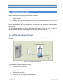
2.1 HARDWARE ARCHITECTURE
The hardware architecture for the construction and operation of the E69Motion software is as
follows:
Figure 2-1. Hardware architecture
The hardware elements used are as follows:
SCN5 electronic actuators
Power supply: 24 V and at least 6A
USB – RS485 converters
USB connection cables
Connectors for the supply and data actuators
User Manual
Page 5 of 22
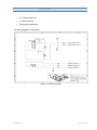
E69 Motion
27 V Zener diode 6A
2.2 Kohm resistor
Emergency pushbutton
The wiring diagram is as follows:
Figure 2-2. Wiring diagram
User Manual
Page 6 of 22
E69 Motion
2.2 SOFTWARE ARCHITECTURE
The software architecture is based on a typical multi-thread software architecture. The
threads are connected through an internal bus.
Figure 2-3. Software architecture
2.3 SOFTWARE REQUIREMENTS
The E69Motion software requires the following elements to be installed in a PC to operate
correctly:
-
32/64 bit Windows XP/7 operating system
-
.NET Framework 4
-
Redistributable Visual C++
The user will have an installer that will copy whatever is required to make the application
work onto the PC file system. A shortcut to the application will be created on the desktop.
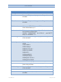
2.4 SIMULATOR PLUGINS
The software communication with the simulators is done through the API provided by each of
the simulators. Some do not require any action by the user, whereas others require files to
be copied or configured in a given way.
The following list includes the instructions to be followed to operate the API of each
simulator:
User Manual
Page 7 of 22
E69 Motion
Simulator
Configuration
iRacing
N/A
Rfactor
Paste the E69_rfactor.dll plugin in the Plugins folder of the
simulator.
Rfactor2
Paste the E69_rfactor2.dll plugin in the Plugins folder of the
simulator.
Simbin series
N/A, except GTR2. Edit the user PLR:
Write Shared Memory="1"
Codemaster series
Edit the hardware_settings_config.xml file of each simulator
and include the following line:
<motion enabled="true"
delay="0" extradata="1" />
ip="127.0.0.1"
port="20777"
Kart Racing Pro
Paste the E69_kartracingpro.dll plugin in the Plugins folder
of the simulator.
Live for Speed
Edit the cfg.txt file in the simulator folder with the following
values:
OutSim Mode 1
OutSim Delay 0
OutSim IP 127.0.0.1
OutSim Port 32069
OutSim ID 0
OutGauge Mode 1
OutGauge Delay 0
OutGauge IP 127.0.0.1
OutGauge Port 32169
RBR
Run the attached program: RBRRealtimePhysics.exe
Game Stock Car
Paste the E69_GameStockCar.dll plugin in the Plugins
folder of the simulator.
SimRaceWay
Paste the E69_SimRaceWay.dll plugin in the Plugins folder
of the simulator.
DCS World
** Instructions at the end of this table
X-Plane
Configure the export of pitch and roll data within the
simulator.
User Manual
Page 8 of 22
E69 Motion
Fligth simulator
N/A
IL2 1946
Add this section to the conf.ini file:
[DeviceLink]
port=35069
Falcon 4
N/A
** Instructions to configure DCS World:
Modify the export.lua file and include the following parameters in the functions:
function LuaExportStart():
package.path = package.path..";.\\LuaSocket\\?.lua"
package.cpath = package.cpath..";.\\LuaSocket\\?.dll"
host, port = "localhost", 36069
socket = require("socket")
ip = socket.try(socket.dns.toip(host))
udp = socket.try(socket.udp())
function LuaExportAfterNextFrame()
local pitch, bank, yaw = LoGetADIPitchBankYaw()
socket.try(udp:sendto(string.format("%.2f;%.2f;%.2f", pitch, bank, yaw), ip, port))
function LuaExportStop()
socket.try(udp:close())
User Manual
Page 9 of 22
E69 Motion
3.
GRAPHICAL USER INTERFACE
The E69Motion software has been created so that any user with a motion chassis based on
SCN5 actuators can have a user-friendly and simple configuration interface.
The interface includes the following elements:
Figure 3-1. Parts of the application
1. Logykal logo. Image of the banner of the Logykal work group and the logo of the
Escuadrón 69. Clicking on it opens the Logykal web page in an Internet browser
2. Configuration. The information has been divided into tabs, each including the
following:
General. This includes the controls needed to detect the SNC5 actuators, to calibrate
them, perform simple tests, configure the basic parameters of the actuators, configure
the effect to be obtained from the seat and an emergency stop.
User Manual
Page 10 of 22
E69 Motion
Figure 3-2. General tab
Network. The software can send information on the motion through a LAN network,
so controls have been created for its correct handling.
Figure 3-3. Network tab
About. This tab contains information on the Logykal team, supported simulators,
version number, etc.
Figure 3-4. About tab
User Manual
Page 11 of 22
E69 Motion
3. Application buttons: these buttons can be used for the following operations:
Close. Close the application.
Save. Save the selected values of all the parameters with the current profile name.
The user will be prompted to confirm the name.
Save as. Save the selected values of all the parameters with a profile name. The
user will be prompted to confirm the name.
Auto-Find: Begins an automatic search for actuators to start the application.
3.1 GENERAL
The application will open in the General tab. This tab includes all the system configuration,
parameter adjustments and tests.
3.1.1 Configuration
The Configuration tab includes drop-down menus to select the type of configuration of each
system, the simulator the information is to be obtained from and the name of the
configuration profile to be loaded.
Figure 3-5. Configuration group
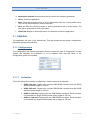
3.1.1.1 Actuators
This menu allows the hardware configuration of each system to be selected:
User Manual
SCN5 (150 mm). System with a single USB-RS485 converter and two SCN5
actuators with a length of 150 mm.
SCN5 (100 mm). System with a single USB-RS485 converter and two SCN5
actuators with a length of 100 mm.
SCN5 x2 (150 mm). System with two USB-RS485 converters. Each converter
is connected to a single SCN5 actuator with a length of 150 mm.
SCN5 x2 (100 mm). System with two USB-RS485 converters. Each converter
is connected to a single SCN5 actuator with a length of 100 mm.
Page 12 of 22
E69 Motion
Warner. Actuators by Warner that will be available in the motion chassis
created by Logykal.
Figure 3-6. List of available actuators
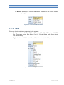
3.1.1.2 Game
This menu lists the simulators supported by the software:
Racing simulators: iRacing, RFactor, RFactor2, GTR, GTL, GTR2, Race 07, GTR
Evo, Codemaster Series, Kart Racing Pro, LfS, Richard Burns Rally, Game Stock
Car, SimRaceWay.
Flight simulators: DCS World, X-Plane, Flight Simulator X, IL2 1946, Falcon4.
Figure 3-7. List of supported simulators
User Manual
Page 13 of 22
E69 Motion
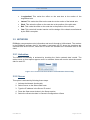
3.1.1.3 Configuration
Since all vehicles behave differently, the configuration parameters of the actuators and of the
effects can be stored in a file generated by the application. This menu can be used to select
the stored profile. The values will be automatically loaded in the application and applied
instantly.
Figure 3-8. List of stored profiles
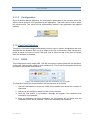
3.1.2 Com Port Selection
This group of controls changes automatically once the type of system configuration has been
selected with the actuator menu so as to adapt to the type of connection used. Whenever a
profile is saved, the name of each COM port used is stored so that it can then be loaded
when the software is restarted.
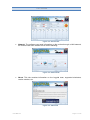
3.1.2.1 SCN5
This configuration uses a single USB – RS-485 converter to communicate with two actuators.
In this case, each actuator needs to have a different ID. This ID can be changed with the tool
provided by the actuator manufacturer.
Figure 3-9. Communication with two actuators, one converter
The operation to start the communication with the actuators is as follows:
1. Use the COM selector to select the COM communication port where the converter is
connected
2. Use Id Left and Id Right to select the IDs of every actuator
3. Click the Find button. A confirmation message will appear if the detection was
successful or not possible.
4. Once the detection has been successful, the Find button will be hidden and the
Calibration button will be available. This button calibrates both actuators.
User Manual
Page 14 of 22
E69 Motion
3.1.2.2 SCN5 x2
This configuration uses to USB – RS-485 converters that are connected to a single SCN5
actuator.
Figure 3-10. Communication with two actuators, two converters
The operation to communicate with two actuators is similar to the SCN5 operation. The same
steps have to be followed with both COM ports.
3.1.3 Test
Once the actuators have been located and calibrated, their operation can be verified by
means of two sliding controls that send a position to each actuator.
Figure 3-11. Individual simple test of each actuator
These controls stop having an effect on the actuators once the user has opened a simulator.
3.1.4 Emergency stop
The motion can be stopped by clicking on the image of the emergency pushbutton if
off-normal system operation is encountered.
Figure 3-12. Emergency pushbutton
User Manual
Page 15 of 22
E69 Motion
3.1.5 Actuator Settings
The application includes a series of settings that provide basic and sufficient control over the
actuator operation. These controls affect both actuators simultaneously.
Figure 3-13. Actuator configuration controls
All selectors have a range between 0 and 100 and alter the following configuration:
Central Pos. This particular control does not actuate directly on an actuator motion
parameter, but it does alter the intermediate position of the actuator. Depending on
the system, there may be a slight difference in the horizontality with respect to the
central point of the actuator. Altering the control means the seat may get to be
horizontal with respect to the ground.
Speed. Actuators can reach a speed of 400 mm/sec. This control allows the
percentage of the maximum actuator speed to be selected.
Acceleration. Actuators have a maximum acceleration of 200 mm/sec2. This control
allows the percentage of the maximum actuator acceleration to be selected.
Length. This control varies the maximum length of motion of both actuators.
3.1.6 Motion settings
All the simulators that are supported in this software generate motion values. These values
are exported through the internal API and are then processed so that a position is generated
in the actuators to simulate the motion on the seat position.
User Manual
Page 16 of 22
E69 Motion
Figure 3-14. Motion axes of a vehicle
The effects provided by every vehicle can be adjusted by means of a series of controls,
which range between 0% and 100% of the maximum effects for every simulator.
Figure 3-15. Effect configuration controls
Linearity. This modifies the output values respect input variables (vehicle
telemetry) with non-linearly signal:
Figura 3-16. Output linearity
User Manual
Page 17 of 22
E69 Motion
Longitudinal. This varies the effect on the seat due to the motion of the
longitudinal axis.
Lateral. This varies the effect on the seat due to the motion of the lateral axis.
Pitch. This varies the effect on the seat due to the position of the pitch axis.
Roll. This varies the effect on the seat due to the position of the roll axis.
Yaw. This control will remain inactive until the design of the chassis manufactured
by the E69 is complete.
3.2 NETWORK
E69Motion can generate motion information and send it through a LAN network. The receiver
is the E69Motion software itself. If this option is activated, the PC where the simulators are
executed acts as the server, while the PC where the actuators are connected acts as the
client.
3.2.1 Activation
The Network functionality is activated by checking the ‘Active network data’ control. The
active server or client options appear once it is activated. Users will need to select the correct
side for each PC.
Figure 3-17. Controls for the activation of the Network functionality
3.2.2 Server
This option is activated by following these steps:
1. Activate the Network functionality
2. Select Server on the Select Side menu
3. Type the IP address in the Server IP control
4. Press the Open server button in the Server section
5. Select the correct simulator in General->Configuration->Game
User Manual
Page 18 of 22
E69 Motion
Figure 3-18. Server functionality
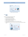
3.2.3 Client
This option is activated by following these steps:
1. Activate the Network functionality
2. Select and locate the SCN5 actuators
3. Select Client on the Select side menu
6. Type the IP address in the Server IP control
7. Press the Connect to server button
8. If the connection is made, the Check status LED will appear in green
4. The actuators will now move if the server enters the simulator and starts the vehicle
motion
Figure 3-19. Client functionality
User Manual
Page 19 of 22
E69 Motion
3.3 ABOUT
This tab displays information on the members of the Logykal team, the supported simulators,
licence, version and acknowledgements. It also includes an image of the Escuadrón 69 logo.
Figure 3-20. About tab
3.4 APPLICATIONS BUTTONS
There are the buttons in charge to close, save actual configuration, save actual configuration
with another name or begin the auto-search of the actuators.
Figura 3-21. Botones de aplicación
Close. Closet he application
Save. Save the actual profile and all general configurations.
Save as. Show a window to enter the new profile name.
Auto-Find. If the user checks the control, you must press Save button. At the next
software start, it begin to auto find your actuators.
User Manual
Page 20 of 22
E69 Motion
4.
LICENCE
This software is distributed under a Creative Commons – Non-commercial – No derivative
works 3.0 licence. The software is freely distributable and only for personal use. Commercial
licences may be obtained by contacting the developer, Fernando Núñez Correas, at
[email protected].
The complete text of the licence can be found here:
http://creativecommons.org/licenses/by-nc-nd/3.0/legalcode
In addition to the free use for private users, monetary donations are accepted. Any
help that can be provided to develop this software will be accepted. Donations can be
sent to the following PayPal address: [email protected]. To use other methods,
please contact the developer. Thank you!
User Manual
Page 21 of 22
E69 Motion
5.
SUPPORT
If users encounter any problems, they can send the developer an e-mail at
[email protected]. Priority will be given to those users that have made donations to the
project.
User Manual
Page 22 of 22