1
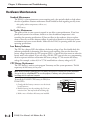
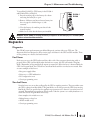
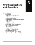
MAINTENANCE AND
TROUBLESHOOTING
CHAPTER
9
In This Chapter...
Hardware Maintenance . . . . . . . . . . . . . . . . . . . . . . . . . . . . . . . . . .9–2
Diagnostics . . . . . . . . . . . . . . . . . . . . . . . . . . . . . . . . . . . . . . . . . . .9–3
CPU Error Indicators . . . . . . . . . . . . . . . . . . . . . . . . . . . . . . . . . . . .9–10
PWR Indicator . . . . . . . . . . . . . . . . . . . . . . . . . . . . . . . . . . . . . . . .9–11
Communications Problems . . . . . . . . . . . . . . . . . . . . . . . . . . . . . .9–13
I/O Module Troubleshooting . . . . . . . . . . . . . . . . . . . . . . . . . . . . .9–14
Noise Troubleshooting . . . . . . . . . . . . . . . . . . . . . . . . . . . . . . . . . .9–17
Machine Startup and Program Troubleshooting . . . . . . . . . . . . . . .9–18
Chapter 9: Maintenance and Troubleshooting
Standard Maintenance
The DL205 is a low maintenance system requiring only a few periodic checks to help reduce
the risks of problems. Routine maintenance checks should be made regarding two key items.
• Air quality (cabinet temperature, airflow, etc.)
• CPU battery
Air Quality Maintenance
The quality of the air your system is exposed to can affect system performance. If you have
placed your system in an enclosure, check to see that the ambient temperature is not
exceeding the operating specifications. If there are filters in the enclosure, clean or replace
them as necessary to ensure adequate airflow. A good rule of thumb is to check your system
environment every one to two months. Make sure the DL205 is operating within the system
operating specifications.
Low Battery Indicator
The CPU has a battery LED that indicates the battery voltage is low. You should check this
indicator periodically to determine if the battery needs replacing. You can also detect low
battery voltage from within the CPU program. SP43 is a special relay that comes on when the
battery needs to be replaced. If you are using a DL240 CPU, you can also use a programming
device or operator interface to determine the battery voltage. V7746 contains the battery
voltage. For example, a value of 32 in V7746 would indicate a battery voltage of 3.2V.
CPU Battery Replacement
9–2
The CPU battery is used to retain program V-memory and the system parameters. The life
expectancy of this battery is five years.
NOTE: Before installing or replacing your CPU battery, back-up your V-memory and system parameters.
You can do this by using DirectSOFT to save the program, V-memory, and system parameters to
hard/floppy disk on a personal computer.
To install the D2–BAT CPU battery in DL230 or
DL240 CPUs:
1. Gently push the battery connector onto the circuit
board connector.
Maintenance
and Troubleshooting
1
2
3
4
5
6
7
8
9
10
11
12
13
14
A
B
C
D
Hardware Maintenance
2. Push the battery into the retaining clip. Don’t use
excessive force. You may break the retaining clip.
3. Make a note of the date the battery was installed.
DL205 User Manual, 4th Edition, Rev. B
DL230
and
DL240
Chapter 9: Maintenance and Troubleshooting
To install the D2–BAT–1 CPU battery in the DL250–1
and DL260 CPUs: (#CR2354)
1. Press the retaining clip on the battery door down
and swing the battery door open.
DL250–1
DL260
2. Remove old battery and insert the new battery into
the coin–type slot with the larger (+) side
outwards.
3. Close the battery door making sure that it locks
securely in place.
4. Make a note of the date the battery was installed.
WARNING: Do not attempt to recharge the battery or dispose of an old battery by fire. The battery may
explode or release hazardous materials.
Diagnostics
Diagnostics
Your DL205 system performs many pre-defined diagnostic routines with every CPU scan. The
diagnostics have been designed to detect various types of failures for the CPU and I/O modules. There
are two primary error classes, fatal and non-fatal.
Fatal Errors
Fatal errors are errors the CPU has detected that offer a risk of the system not functioning safely or
properly. If the CPU is in Run Mode when the fatal error occurs, the CPU will switch to Program
Mode. (Remember, in Program Mode all outputs are turned off.) If the fatal error is detected while the
CPU is in Program Mode, the CPU will not enter Run Mode until the error has been corrected. Here
are some examples of fatal errors.
• Base power supply failure
• Parity error or CPU malfunction
• I/O configuration errors
• Certain programming errors
Non-fatal Errors
Non-fatal errors are errors that are flagged by the CPU as requiring attention. They can neither cause
the CPU to change from Run Mode to Program Mode, nor do they prevent the CPU from entering
Run Mode. There are special relays the application program can use to detect if a non-fatal error has
occurred. The application program can then be used to take the system to an orderly shutdown or to
switch the CPU to Program Mode if necessary.
Some examples of non-fatal errors are:
• Backup battery voltage low
• All I/O module errors.
• Certain programming errors
DL205 User Manual, 4th Edition, Rev. B
1
2
3
4
5
6
7
8
9
10
11
12
13
14
A
B
C
D
9–3
Chapter 9: Maintenance and Troubleshooting
Finding Diagnostic Information
1
2
3
4
5
6
7
8
9
10
11
12
13
14
A
B
C
D
Diagnostic information can be found in several places with varying levels of message detail.
• The CPU automatically logs error codes and any FAULT messages into two separate tables which
can be viewed with the Handheld or DirectSOFT.
• The handheld programmer displays error numbers and short descriptions of the error.
• DirectSOFT provides the error number and an error message.
• Appendix B in this manual has a complete list of error messages sorted by error number.
Many of these messages point to supplemental memory locations which can be referenced for
additional related information. These memory references are in the form of V-memory and
SPs (special relays).
The following two tables name the specific memory locations that correspond to certain types
of error messages. The special relay table also includes status indicators which can be used in
programming. For a more detailed description of each of these special relays refer to
Appendix D.
V-memory Locations Corresponding to Error Codes
9–4
Error Class
Error Category
Battery Voltage (DL240 only) Shows battery voltage to tenths (32 is 3.2V)
User-Defined
Error code used with FAULT instruction
Correct module ID code
I/O Configuration
Incorrect module ID code
Base and Slot number where error occurs
Fatal Error code
System Error
Major Error code
Minor Error code
Base and slot number where error occurs
Module Diagnostic
Always holds a “O”
Error code
Address where syntax error occurs
Grammatical
Error code found during syntax check
Number of scans since last Program to Run Mode transition
Current scan time (ms)
CPU Scan
Minimum scan time (ms)
Maximum scan time (ms)
DL205 User Manual, 4th Edition, Rev. B
Diagnostic
V-memory
V7746
V7751
V7752
V7753
V7754
V7755
V7756
V7757
V7760
V7761
V7762
V7763
V7764
V7765
V7775
V7776
V7777
Chapter 9: Maintenance and Troubleshooting
Special Relays (SP) Corresponding to Error Codes
Startup and Real-time Relays
SP0
SP1
SP2
SP3
SP4
SP5
SP6
SP7
On first scan only
Always ON
Always OFF
1 minute clock
1 second clock
100 millisecond clock
50 millisecond clock
On alternate scans
CPU Status Relays
SP11
SP12
SP13
SP15
SP16
SP20
SP22
Forced Run mode
(DL240/250-1/260)
Terminal Run mode
Test Run mode
(DL240/250-1/260)
Test program mode
(DL240/250-1/260)
Terminal Program mode
STOP instruction was executed
Interrupt enabled
System Monitoring Relays
SP40
SP41
SP43
SP44
SP45
SP46
SP47
SP50
SP51
SP52
SP53
Critical error
Non-critical error
Battery low
Program memory error
I/O error
Communications error
I/O configuration error
Fault instruction was executed
Watchdog timeout
Syntax error
Cannot solve the logic
SP54
Intelligent module
communication error
Accumulator Status Relays
SP60
SP61
SP62
SP63
SP64
SP65
SP66
SP67
SP70
SP71
SP73
SP75
SP76
Acc. is less than value
Acc. is equal to value
Acc. is greater than value
Acc. result is zero
Half borrow occurred
Borrow occurred
Half carry occurred
Carry occurred
Result is negative (sign)
Pointer reference error
Overflow
Data is not in BCD
Load zero
Communication Monitoring Relays
SP116
(DL230/DL240)
SP116
(DL250-1/DL260)
CPU is communicating with
another device
SP117
Communication error on Port 2
(DL250-1/DL260 only)
SP120
SP121
SP122
SP123
SP124
SP125
SP126
SP127
SP130
SP131
SP132
SP133
SP134
SP135
SP136
SP137
Module busy, Slot 0
Communication error Slot 0
Module busy, Slot 1
Communication error Slot 1
Module busy, Slot 2
Communication error Slot 2
Module busy, Slot 3
Communication error Slot 3
Module busy, Slot 4
Communication error Slot 4
Module busy, Slot 5
Communication error Slot 5
Module busy, Slot 6
Communication error Slot 6
Module busy, Slot 7
Communication error Slot 7
Port 2 is communicating with
another device
DL205 User Manual, 4th Edition, Rev. B
1
2
3
4
5
6
7
8
9
10
11
12
13
14
A
B
C
D
9–5
Chapter 9: Maintenance and Troubleshooting
I/O Module Codes
Maintenance
and Troubleshooting
1
2
3
4
5
6
7
8
9
10
11
12
13
14
A
B
C
D
9–6
Each system component has a code identifier. This code identifier is used in some of the error
messages related to the I/O modules. The following table shows these codes.
Code
(Hex)
04
03
20
21
CPU
I/O Base
8 pt. Output
8 pt. Input
24
4 input/output
combination
28
3F
30
52
51
Code
(Hex)
Component Type
12 pt. Output
16 pt. Output
32 pt. Input
32 pt. Output
H2-ERM(100)
H2-CTRIO(2)
36
2B
37
3D
4A
7F
FF
EE
BE
Component Type
Analog Input
16 pt. Input
Analog Output
Analog I/O Combo
Counter Interface
Abnormal
No module detected
D2-DCM
H2-ECOM
F2-CP128
D2-RMSM
The following diagram shows an example of how the I/O module codes are used:
Program Control Information
V7752 0020 Desired module ID code
V7753 0026 Current module ID code
V7754 0002 Location of conflict
V7755 0252 Fatal error code
SP47
I/O Configuration Error
DL205 User Manual, 4th Edition, Rev. B
E252
NEW I/O CFG
Chapter 9: Maintenance and Troubleshooting
Error Message Tables
ý 230
þ 240
þ 250-1
þ 260
The DL240/250-1/260 CPUs will automatically log any system error codes and any custom
messages you have created in your application program with the FAULT instructions. The
CPU logs the error code, the date, and the time the error occurred. There are two separate
tables that store this information.
• Error Code Table – the system logs up to 32 errors in the table. When an error occurs, the
errors already in the table are pushed down and the most recent error is loaded into the
top position. If the table is full when an error occurs, the oldest error is pushed (erased)
from the table.
• Message Table – the system logs up to 16 messages in this table. When a message is
triggered, the messages already stored in the table are pushed down and the most recent
message is loaded into the top position. If the table is full when an error occurs, the oldest
message is pushed (erased) from the table.
The following diagram shows an example of an error table for messages.
Date
Time
2008-05-26
2008-04-30
2008-04-30
2008-04-28
Message
08:41:51:11
17:01:11:56
17:01:11:12
03:25:14:31
*Conveyor-2 stopped
*Conveyor-1 stopped
*Limit SW1 failed
*Saw Jam Detect
You can access the error code table and the message table through DirectSOFT’s PLC
Diagnostic sub-menus or from the Handheld Programmer. Details on how to access these
logs are provided in the DirectSOFT manual.
The following examples show you how to use the Handheld and AUX Function 5C to show
the error codes. The most recent error or message is always displayed. You can use the PREV
and NXT keys to scroll through the messages.
Use AUX 5C to view the tables
CLR
F
5
SHFT
C
2
AUX
AUX 5C HISTORY D
ERROR/MESAGE
ENT
Use the arrow key to select Errors or Messages
AUX 5C HISTORY D
ERROR/MESAGE
ENT
Example of an error display
E252NEW I/O CFG
08/09/21 10:11:15
Month
Day
Time
DL205 User Manual, 4th Edition, Rev. B
9–7
Maintenance
and Troubleshootin
Year
1
2
3
4
5
6
7
8
9
10
11
12
13
14
A
B
C
D
Chapter 9: Maintenance and Troubleshooting
System Error Codes
1
2
3
4
5
6
7
8
9
10
11
12
13
14
A
B
C
D
ý 230
þ 240
þ 250-1
þ 260
The System error log contains 32 of the most recent errors that have been detected. The
errors that are trapped in the error log are a subset of all the error messages which the DL205
systems generate. These errors can be generated by the CPU or by the Handheld Programmer,
depending on the actual error. Appendix B provides a more complete description of the error
codes.
The errors can be detected at various times. However, most of them are detected at power-up,
on entry to Run Mode, or when a Handheld Programmer key sequence results in an error or
an illegal request.
Error Code
E003
E004
E041
E043
E099
E101
E104
E151
E155
E201
E202
E203
E206
E210
E250
E251
E252
E262
E312
E313
E316
E320
E321
E499
E501
E502
E503
E504
E505
9–8
Description
Software time-out
Invalid instruction(RAM parity error in the CPU)
CPU battery low
Memory cartridge battery low
Program memory exceeded
CPU memory cartridge missing
Write fail
Invalid command
RAM failure
Terminal block missing
Missing I/O module
Blown fuse
User 24V power supply failure
Power fault
Communication failure in the I/O chain
I/O parity error
New I/O configuration
I/O out of range
Communications error 2
Communications error 3
Communications error 6
Time out
Communications error
Invalid Text entry for Print Instruction
Bad entry
Bad address
Bad command
Bad reference / value
Invalid instruction
DL205 User Manual, 4th Edition, Rev. B
Error Code
E506
E520
E521
E523
E524
E525
E526
E527
E528
E540
E541
E542
E601
E602
E604
E610
E611
E620
E621
E622
E624
E625
E627
E628
E640
E650
E651
E652
Description
Invalid operation
Bad operation - CPU in Run
Bad operation - CPU in Test Run
Bad operation - CPU in Test Program
Bad operation - CPU in Program
Mode Switch not in TERM
Unit is offline
Unit is online
CPU mode
CPU locked
Wrong password
Password reset
Memory full
Instruction missing
Reference missing
Bad I/O type
Bad Communications ID
Out of memory
EEPROM Memory not blank
No Handheld Programmer EEPROM
V-memory only
Program only
Bad write operation
Memory type error (should be EEPROM)
Mis-compare
Handheld Programmer system error
Handheld Programmer ROM error
Handheld Programmer RAM error
Chapter 9: Maintenance and Troubleshooting
Program Error Codes
The following list shows the errors that can occur when there are problems with the program.
These errors will be detected when you try to place the CPU into Run Mode, or, when you
use AUX 21 – Check Program. The CPU will also turn on SP52 and store the error code in
V7755. Appendix B provides a more complete description of the error codes.
Error Code
E4**
E401
E402
E403
E404
E405
E406
E412
E413
E421
E422
E423
E431
E432
E433
E434
E435
E436
E437
E438
E440
E441
E451
E452
E453
E454
E455
E456
Description
No Program in CPU
Missing END statement
Missing LBL
Missing RET
Missing FOR
Missing NEXT
Missing IRT
SBR/LBL >64
FOR/NEXT >64
Duplicate stage reference
Duplicate SBR/LBL reference
Nested loops
Invalid ISG/SG address
Invalid jump (GOTO) address
Invalid SBR address
Invalid RTC address
Invalid RT address
Invalid INT address
Invalid IRTC address
Invalid IRT address
Invalid Data address
ACON/NCON
Bad MLS/MLR
X input used as output coil
Missing T/C
Bad TMRA
Bad CNT
Bad SR
Error Code
E461
E462
E463
E464
E471
E472
E473
E480
E481
E482
E483
E484
E485
E486
E487
E488
E489
E490
E491
E492
E493
E494
Description
Stack Overflow
Stack Underflow
Logic Error
Missing Circuit
Duplicate coil reference
Duplicate TMR reference
Duplicate CNT reference
CV position error
CV not connected
CV exceeded
CVJMP placement error
No CV
No CVJMP
BCALL placement error
No Block defined
Block position error
Block CR identifier error
No Block stage
ISG position error
BEND position error
BEND I error
No BEND
DL205 User Manual, 4th Edition, Rev. B
1
2
3
4
5
6
7
8
9
10
11
12
13
14
A
B
C
D
9–9
Chapter 9: Maintenance and Troubleshooting
1
2
3
4
5
6
7
8
9
10
11
12
13
14
A
B
C
D
CPU Error Indicators
9–10
The DL205 CPUs have indicators on the front to help you diagnose problems with the
system. The table below gives a quick reference of potential problems associated with each
status indicator. Following the table will be a detailed analysis of each of these indicator
problems.
Indicator Status
Potential Problems
1. System voltage incorrect
2. Power supply/CPU is faulty
3. Other component such an I/O module has power supply shorted
4. Power budget exceeded for the base being used
1. CPU programming error
2. Switch in TERM position
3. Switch in STOP position (DL250-1, DL260 only)
Firmware upgrade mode
1. Electrical noise interference
2. CPU defective
1. CPU battery low
2. CPU battery missing, or disconnected
PWR (off)
RUN (will not come on)
RUN (flashing)
CPU (on)
BATT (on)
Status Indicators
PWR
PWR
BATT
RUN
CPU
BATT
DL240
Port 1
DL230
RUN
CPU
CPU
CPU
RUN
CH1
CH2
CH3
CH4
PORT1
Port 2
PORT1
PORT2
Status Indicators
DL260
DL250-1
Mode Switch
Port 1
Port 2
Battery Slot
DL205 User Manual, 4th Edition, Rev. B
Mode Switch
TERM
Analog
Adjustments
Chapter 9: Maintenance and Troubleshooting
PWR Indicator
There are four general reasons for the CPU power status LED (PWR) to be OFF:
1. Power to the base is incorrect or is not applied.
2. Base power supply is faulty.
3. Other component(s) have the power supply shut down.
4. Power budget for the base has been exceeded.
Incorrect Base Power
If the voltage to the power supply is not correct, the CPU and/or base may not operate
properly or may not operate at all. Use the following guidelines to correct the problem.
WARNING: To minimize the risk of electrical shock, always disconnect the system power before
inspecting the physical wiring.
1. First, disconnect the system power and check all incoming wiring for loose connections.
2. If you are using a separate termination panel, check those connections to make sure the wiring is
connected to the proper location.
3. If the connections are acceptable, reconnect the system power and measure the voltage at the base
terminal strip to insure it is within specification. If the voltage is not correct shut down the system
and correct the problem.
4. If all wiring is connected correctly and the incoming power is within the specifications required,
the base power supply should be returned for repair.
Faulty CPU
There is not a good check to test for a faulty CPU other than substituting a known good one
to see if this corrects the problem. If you have experienced major power surges, it is possible
the CPU and power supply have been damaged. If you suspect this is the cause of the power
supply damage, a line conditioner which removes damaging voltage spikes should be used in
the future.
DL205 User Manual, 4th Edition, Rev. B
1
2
3
4
5
6
7
8
9
10
11
12
13
14
A
B
C
D
9–11
Chapter 9: Maintenance and Troubleshooting
Device or Module causing the Power Supply to Shutdown
1
2
3
4
5
6
7
8
9
10
11
12
13
14
A
B
C
D
It is possible a faulty module or external device using the system 5V can shut down the power
supply. This 5V can be coming from the base or from the CPU communication ports.
To test for a device causing this problem:
1. Turn off power to the CPU.
2. Disconnect all external devices (i.e., communication cables) from the CPU.
3. Reapply power to the system.
If the power supply operates normally, you may have either a shorted device or a shorted
cable. If the power supply does not operate normally then test for a module causing the
problem by following the steps below:
If the PWR LED operates normally, the problem could be in one of the modules. To isolate
which module is causing the problem, disconnect the system power and remove one module
at a time until the PWR LED operates normally. Follow the procedure below:
• Turn off power to the base.
• Remove a module from the base.
• Reapply power to the base.
Bent base connector pins on the module can cause this problem. Check to see the connector
is not the problem.
Power Budget Exceeded
9–12
If the machine had been operating correctly for a considerable amount of time prior to the
indicator going off, the power budget is not likely to be the problem. Power budgeting
problems usually occur during system start-up when the PLC is under operation and the
inputs/outputs are requiring more current than the base power supply can provide.
WARNING: The PLC may reset if the power budget is exceeded. If there is any doubt about the system
power budget please check it at this time. Exceeding the power budget can cause unpredictable results
which can cause damage and injury. Verify the modules in the base operate within the power budget
for the chosen base. You can find these tables in Chapter 4, Bases and I/O Configuration.
DL205 User Manual, 4th Edition, Rev. B
Chapter 9: Maintenance and Troubleshooting
Run Indicator
If the CPU will not enter the Run mode (the RUN indicator is off ), the problem is usually in
the application program, unless the CPU has a fatal error. If a fatal error has occurred, the
CPU LED should be on. (You can use a programming device to determine the cause of the
error.) If the RUN light is flashing, the PLC is in firmware upgrade mode.
If you are using a DL240, DL250–1 or DL260 and you are trying to change the modes with
a programming device, make sure the mode switch is in the TERM position.
Both of the programming devices, Handheld Programmer and DirectSOFT, will return an
error message describing the problem. Depending on the error, there may also be an AUX
function you can use to help diagnose the problem. The most common programming error is
“Missing END Statement.” All application programs require an END statement for proper
termination. A complete list of error codes can be found in Appendix B.
CPU Indicator
If the CPU indicator is on, a fatal error has occurred in the CPU. Generally, this is not a
programming problem but an actual hardware failure. You can power cycle the system to clear
the error. If the error clears, you should monitor the system and determine what caused the
problem. You will find this problem is sometimes caused by high frequency electrical noise
introduced into the CPU from an outside source. Check your system grounding and install
electrical noise filters if the grounding is suspected. If power cycling the system does not reset
the error, or if the problem returns, you should replace the CPU.
BATT Indicator
If the BATT indicator is on, the CPU battery is either disconnected or needs replacing. The
battery voltage is continuously monitored while the system voltage is being supplied.
Communications Problems
If you cannot establish communications with the CPU, check these items.
• The cable is disconnected.
• The cable has a broken wire or has been wired incorrectly.
• The cable is improperly terminated or grounded.
• The device connected is not operating at the correct baud rate (9600 baud for the top port. Use
AUX 56 to select the baud rate for the bottom port on a DL240, DL250–1 and DL260).
• The device connected to the port is sending data incorrectly.
• A grounding difference exists between the two devices.
• Electrical noise is causing intermittent errors.
• The CPU has a bad communication port and the CPU should be replaced.
If an error occurs, the indicator will come on and stay on until a successful communication
has been completed.
DL205 User Manual, 4th Edition, Rev. B
1
2
3
4
5
6
7
8
9
10
11
12
13
14
A
B
C
D
9–13
and Troubleshooting
Chapter 9: Maintenance and Troubleshooting
1
2
3
4
5
6
7
8
9
10
11
12
13
14
A
B
C
D
I/O Module Troubleshooting
Things to Check
If you suspect an I/O error, there are several things that could be causing the problem.
• A blown fuse
• A loose terminal block
• The 24 VDC supply has failed
• The module has failed
• The I/O configuration check detects a change in the I/O configuration
I/O Diagnostics
9–14
If the modules are not providing any clues to the problem, run AUX 42 from the handheld
programmer or I/O diagnostics in DirectSOFT. Both options will provide the base number,
the slot number and the problem with the module. Once the problem is corrected, the
indicators will reset.
An I/O error will not cause the CPU to switch from the run to program mode; however there
are special relays (SPs) available in the CPU which will allow this error to be read in ladder
logic. The application program can then take the required action, such as entering the
program mode or initiating an orderly shutdown. The following figure shows an example of
the failure indicators.
Program Control Information
V7752 0020 Desired module ID code
V7753 0021 Current module ID code
V7754 0002 Location of conflict
V7755 0252 Fatal error code
SP47
I/O Configuration Error
DL205 User Manual, 4th Edition, Rev. B
E252
NEW I/O CFG
Chapter 9: Maintenance and Troubleshooting
Some Quick Steps
When troubleshooting the DL205 series I/O modules there are a few facts you should be
aware of which may assist you in quickly correcting an I/O problem:
• The output modules cannot detect shorted or open output points. If you suspect one or more
points on an output module to be faulty, you should measure the voltage drop from the common to
the suspect point. Remember, when using a Digital Volt Meter, leakage current from an output
device, such as a triac or a transistor, must be considered. A point which is off may appear to be on
if no load is connected to the point.
• The I/O point status indicators on the modules are logic side indicators. This means the LED
which indicates the on or off status reflects the status of the point in respect to the CPU. On an
output module, the status indicators could be operating normally, while the actual output device
(transistor, triac etc.) could be damaged. With an input module, if the indicator LED is on, the
input circuitry should be operating properly. To verify proper functionality, check to see that the
LED goes off when the input signal is removed.
• Leakage current can be a problem when connecting field devices to I/O modules. False input signals
can be generated when the leakage current of an output device is great enough to turn on the
connected input device. To correct this, install a resistor in parallel with the input or output of the
circuit. The value of this resistor will depend on the amount of leakage current and the voltage
applied but usually a 10KΩ to 20KΩ resistor will work. Ensure the wattage rating of the resistor is
correct for your application.
• The easiest method to determine if a module has failed is to replace it if you have a spare. However,
if you suspect another device to have caused the failure in the module, that device may cause the
same failure in the replacement module as well. As a point of caution, you may want to check
devices or power supplies connected to the failed module before replacing it with a spare module.
DL205 User Manual, 4th Edition, Rev. B
1
2
3
4
5
6
7
8
9
10
11
12
13
14
A
B
C
D
9–15
Chapter 9: Maintenance and Troubleshooting
Testing Output Points
1
2
3
4
5
6
7
8
9
10
11
12
13
14
A
B
C
D
Output points can be set on or off in the DL205 series CPUs. In the DL240 and DL250-1
you can use AUX 59, Bit Override, to force a point even while the program is running.
However, this is not a recommended method to test the output points. If you want to do an
I/O check independent of the application program for either the DL230, DL240, DL250–1
or DL260, follow the procedure below:
Step
Action
1
2
3
Use a handheld programmer or DirectSOFT to communicate online to the PLC.
Change to Program Mode.
Go to address 0.
4
Insert an “END” statement at address 0. (This will cause program execution to occur only at address 0
and prevent the application program from turning the I/O points on or off).
5
6
7
Change to Run Mode.
Use the programming device to set (turn) on or off the points you wish to test.
When you finish testing I/O points delete the “END” statement at address 0.
WARNING: Depending on your application, forcing I/O points may cause unpredictable machine
operation that can result in a risk of personal injury or equipment damage. Make sure you have taken
all appropriate safety precautions prior to testing any I/O points.
Handheld Programmer Keystrokes Used to Test an Output Point
9–16
X0
X2
X1
X3
X5
X4
X7
END
Y2
Insert an END statement
at the beginning of the
program. This disables
the remainder of the
program.
END
From a clear display, use the following keystrokes
STAT
16P STATUS
BIT REF X
ENT
Use the PREV or NEXT keys to select the Y data type
NEXT
A
0
Y 10 Y 0
ENT
Use arrow keys to select point, then use
ON and OFF to change the status
SHFT
ON
INS
DL205 User Manual, 4th Edition, Rev. B
Y2 is now on
Y 10 Y 0
Chapter 9: Maintenance and Troubleshooting
Noise Troubleshooting
Electrical Noise Problems
Noise is one of the most difficult problems to diagnose. Electrical noise can enter a system in
many different ways and falls into one of two categories, conducted or radiated. It may be
difficult to determine how the noise is entering the system but the corrective actions for either
of the types of noise problems are similar.
• Conducted noise is when the electrical interference is introduced into the system by way of an
attached wire, panel connection, etc. It may enter through an I/O module, a power supply
connection, the communication ground connection, or the chassis ground connection.
• Radiated noise is when the electrical interference is introduced into the system without a direct
electrical connection, much in the same manner as radio waves.
Reducing Electrical Noise
While electrical noise cannot be eliminated it can be reduced to a level that will not affect the
system.
• Most noise problems result from improper grounding of the system. A good earth ground can be
the single most effective way to correct noise problems. If a ground is not available, install a ground
rod as close to the system as possible. Ensure all ground wires are single point grounds and are not
daisy chained from one device to another. Ground metal enclosures around the system. A loose wire
is no more than a large antenna waiting to introduce noise into the system; therefore, you should
tighten all connections in your system. Loose ground wires are more susceptible to noise than the
other wires in your system. Review Chapter 2 Installation, Wiring, and Specifications if you have
questions regarding how to ground your system.
• Electrical noise can enter the system through the power source for the CPU and I/O. Installing an
isolation transformer for all AC sources can correct this problem. DC power sources should be well
grounded, good quality power supplies. Switching DC power supplies commonly generate more
noise than linear supplies.
• Separate input wiring from output wiring. Never run I/O wiring close to high voltage wiring.
DL205 User Manual, 4th Edition, Rev. B
1
2
3
4
5
6
7
8
9
10
11
12
13
14
A
B
C
D
9–17
Chapter 9: Maintenance and Troubleshooting
1
2
3
4
5
6
7
8
9
10
11
12
13
14
A
B
C
D
Machine Startup and Program Troubleshooting
The DL205 CPUs provide several features to help you debug your program before and
during machine startup. This section discusses the following topics which can be very helpful.
• Program Syntax Check
• Duplicate Reference Check
• Test Modes
• Special Instructions
• Run Time Edits
• Forcing I/O Points
Syntax Check
9–18
Even though the Handheld Programmer and DirectSOFT provide error checking during
program entry, you may want to check a modified program. Both programming devices offer
a way to check the program syntax. For example, you can use AUX 21, CHECK PROGRAM
to check the program syntax from a Handheld Programmer, or you can use the PLC
Diagnostics menu option within DirectSOFT. This check will find a wide variety of
programming errors. The following example shows how to use the syntax check with a
Handheld Programmer.
Use AUX 21 to perform syntax check
CLR
C
2
B
1
AUX
ENT
Select syntax check (default selection)
ENT
(You may not get the busy display
if the program is not very long.)
One of two displays will appear
Error Display (example)
AUX 21 CHECK PRO
1:SYN 2:DUP REF
BUSY
$00050 E401
MISSING END
(shows location in question)
Syntax OK display
NO SYNTAX ERROR
?
See the Error Codes Section for a complete listing of programming error codes. If you get an
error, press CLR and the Handheld will display the instruction where the error occurred.
Correct the problem and continue running the Syntax check until the NO SYNTAX ERROR
message appears.
DL205 User Manual, 4th Edition, Rev. B
Chapter 9: Maintenance and Troubleshooting
Duplicate Reference Check
You can also check for multiple uses of the same output coil. Both programming devices offer
a way to check for this condition. For example, you can AUX 21, CHECK PROGRAM to
check for duplicate references from a Handheld Programmer, or you can use the PLC
Diagnostics menu option within DirectSOFT. The following example shows how to perform
the duplicate reference check with a Handheld Programmer.
Use AUX 21 to perform syntax check
CLR
C
2
B
1
AUX
ENT
ENT
(You may not get the busy
display if the program is not
very long.)
One of two displays will appear
Error Display (example)
BUSY
Maintenance
and Troubleshooting
Select duplicate reference check
AUX 21 CHECK PRO
1:SYN 2:DUP REF
$00024 E471
DUP COIL REF
(shows location in question)
Syntax OK display
NO DUP REFS
?
Maintenance
and Troubleshooting
If you get an error, press CLR and the Handheld will display the instruction where the error
occurred. Correct the problem and continue running the Duplicate Reference check until no
duplicate references are found.
NOTE: You can use the same coil in more than one location, especially in programs using the Stage
instructions and/or the OROUT instructions. The Duplicate Reference check will find these outputs even
though they may be used in an acceptable fashion.
DL205 User Manual, 4th Edition, Rev. B
1
2
3
4
5
6
7
8
9
10
11
12
13
14
A
B
C
D
9–19
Chapter 9: Maintenance and Troubleshooting
TEST-PGM and TEST-RUN Modes
1
2
3
4
5
6
7
8
9
10
11
12
13
14
A
B
C
D
9–20
Test Mode allows the CPU to start in TEST-PGM mode, enter TEST-RUN mode, run a
fixed number of scans, and return to TEST-PGM mode. You can select from 1 to 65,525
scans. Test Mode also allows you to maintain output status while you switch between TestProgram and Test-Run Modes. You can select Test Modes from either the Handheld
Programmer (by using the MODE key) or from DirectSOFT via a PLC Modes menu option.
The primary benefit of using the TEST mode is to maintain certain outputs and other
parameters when the CPU transitions back to Test-program mode. For example, you can use
AUX 58 from the DL205 Handheld Programmer to configure the individual outputs, CRs,
etc., to hold their output state. Also, the CPU will maintain timer and counter current values
when it switches to TEST-PGM mode.
NOTE: You can only use DirectSOFT to specify the number of scans. This feature is not supported on the
Handheld Programmer. However, you can use the Handheld to switch between Test Program and Test Run
Modes.
With the Handheld, the actual mode entered when you first select Test Mode depends on the
mode of operation at the time you make the request. If the CPU is in Run Mode, then TESTRUN is available. If the mode is Program, then TEST-PGM is available. Once you’ve selected
TEST Mode, you can easily switch between TEST-RUN and TEST-PGM. DirectSOFT
provides more flexibility in selecting the various modes with different menu options. The
following example shows how you can use the Handheld to select the Test Modes.
Use the MODE key to select TEST Modes (example assumes Run Mode)
MODE
NEXT
*MODE CHANGE*
GO TO T–RUN MODE
ENT
Press ENT to confirm TEST-RUN Mode
ENT
(Note, the TEST LED on the DL205
Handheld indicates the CPU is in
TEST Mode.)
*MODE CHANGE*
CPU T–RUN
You can return to Run Mode, enter Program Mode, or enter TEST-PGM
Mode by using the Mode Key
CLR
MODE
NEXT
NEXT
ENT
*MODE CHANGE*
GO TO T–PGM MODE
Press ENT to confirm TEST-PGM Mode
ENT
(Note, the TEST LED on the DL205
Handheld indicates the CPU is in
TEST Mode.)
DL205 User Manual, 4th Edition, Rev. B
*MODE CHANGE*
CPU T–PGM
Chapter 9: Maintenance and Troubleshooting
Test Displays: With the Handheld Programmer you also have a more detailed display when
you use TEST Mode. For some instructions, the TEST-RUN mode display is more detailed
than the status displays shown in RUN mode. The following diagram shows an example of a
Timer instruction display during TEST-RUN mode.
RUN Mode
TMR T0 K1000
TEST-RUN Mode
S
S
T0 Contact (S is off)
(is on)
Current Value
Input to Timer
Maintenance
and Troubleshooting
T0 Contact (S is off)
(is on)
1425
TMR T0 K1000
Holding Output States: The ability to hold output states is very useful because it allows you
to maintain key system I/O points. In some cases, you may need to modify the program, but
you do not want certain operations to stop. In normal Run Mode, the outputs are turned off
when you return to Program Mode. In TEST-RUN mode, you can set each individual output
to either turn off, or to hold its last output state on the transition to TEST-PGM mode. You
can use AUX 58 on the Handheld Programmer to select the action for each individual
output. This feature is also available via a menu option within DirectSOFT. The following
diagram shows the differences between RUN and TEST-RUN modes.
RUN Mode to PGM Mode
X0
X1
Status on final scan
X0
X1
X4
Y0
Y1
END
X4
X10
Y0
Outputs are
OFF
Y1
END
TEST-RUN to TEST-PGM
Y0
X0
X2
X1
X10
X3
X4
Let Y1 turn
OFF
Hold Y0 ON
Y1
END
Maintenance
and Troubleshooting
X10
X2
X3
X2
X3
Before you decide that Test Mode is the perfect choice, remember that the DL205 CPUs also
allow you to edit the program during Run Mode. The primary difference between the Test
Modes and the Run Time Edit feature is you do not have to configure each individual I/O
point to hold the output status. When you use Run Time Edits, the CPU automatically
maintains all outputs in their current states while the program is being updated.
DL205 User Manual, 4th Edition, Rev. B
1
2
3
4
5
6
7
8
9
10
11
12
13
14
A
B
C
D
9–21
Chapter 9: Maintenance and Troubleshooting
Special Instructions
1
2
3
4
5
6
7
8
9
10
11
12
13
14
A
B
C
D
9–22
There are several instructions that can be used to help you debug your program during
machine startup operations.
• END
• PAUSE
• STOP
END Instruction: If you need a way to quickly disable part of the program, insert an END
statement prior to the portion that should be disabled. When the CPU encounters the END
statement, it assumes it is the end of the program. The following diagram shows an example.
X0
X1
Normal Program
X2
X3
X4
Y0
New END disables X10 and Y1
X0
X1
X2
X3
X4
Y1
X10
END
Y0
END
Y1
X10
END
PAUSE Instruction: This instruction provides a quick way to allow the inputs (or other logic)
to operate while disabling selected outputs. The output image register is still updated, but the
output status is not written to the modules. For example, you could make this conditional by
adding an input contact or CR to control the instruction with a switch or a programming
device. Or, you could add the instruction without any conditions so the selected outputs
would be disabled at all times.
X0
X1
X10
Normal Program
X2
X3
X4
Y0
Y1
END
PAUSE disables Y0 and Y1
Y0 – Y1
X0
X1
X10
X2
X3
PAUSE
X4
Y0
Y1
END
DL205 User Manual, 4th Edition, Rev. B
Chapter 9: Maintenance and Troubleshooting
STOP Instruction: Sometimes during machine startup you need a way to quickly turn off all
the outputs and return to Program Mode. In addition to using the Test Modes and AUX 58
(to configure each individual point), you can also use the STOP instruction. When this
instruction is executed, the CPU automatically exits Run Mode and enters Program Mode.
Remember, all outputs are turned off during Program Mode. The following diagram shows an
example of a condition that returns the CPU to Program Mode.
X0
X10
X2
X3
X4
Y0
Y1
END
STOP puts CPU in Program Mode
X20
X0
X1
X10
X2
X3
STOP
X4
Y0
Y1
END
Maintenance
and Troubleshooting
X1
Normal Program
In the example shown above, you could trigger X20 which would execute the STOP
instruction. The CPU would enter Program Mode and all outputs would be turned off.
Maintenance
and Troubleshooting
DL205 User Manual, 4th Edition, Rev. B
1
2
3
4
5
6
7
8
9
10
11
12
13
14
A
B
C
D
9–23
Chapter 9: Maintenance and Troubleshooting
Run Time Edits
1
2
3
4
5
6
7
8
9
10
11
12
13
14
A
B
C
D
The DL205 CPUs allow you to make changes to the application program during Run Mode.
These edits are not “bumpless.” Instead, CPU scan is momentarily interrupted (and the
outputs are maintained in their current state) until the program change is complete. This
means if the output is off, it will remain off until the program change is complete. If the
output is on, it will remain on.
WARNING: Only authorized personnel fully familiar with all aspects of the application should make
changes to the program. Changes during Run Mode become effective immediately. Make sure you
thoroughly consider the impact of any changes to minimize the risk of personal injury or damage to
equipment. There are some important operations sequence changes during Run Time Edits.
1. If there is a syntax error in the new instruction, the CPU will not enter the Run Mode.
2. If you delete an output coil reference and the output was on at the time, the output will remain on
until it is forced off with a programming device.
3. Input point changes are not acknowledged during Run Time Edits. So, if you’re using a high-speed
operation and a critical input comes on, the CPU may not see the change.
Not all instructions can be edited during a Run Time Edit session. The following list shows
Mnemonic
TMR
TMRF
TMRA
TMRAF
CNT
UDC
SGCNT
STR, STRN
AND, ANDN
OR, ORN
STRE, STRNE
ANDE, ANDNE
ORE, ORNE
STR, STRN
AND, ANDN
9–24
Description
Timer
Fast timer
Accumulating timer
Accumulating fast timer
Counter
Up / Down counter
Stage counter
Store, Store not
And, And not
Or, Or not
Store equal, Store not equal
And equal, And not equal
Or equal, Or not equal
Store greater than or equal
Store less than
And greater than or equal
And less than
Mnemonic
OR, ORN
LD
LDD
ADDD
SUBD
MUL
DIV
CMPD
ANDD
ORD
XORD
LDF
OUTF
SHFR
SHFL
NCON
Description
Or greater than or equal, Or less than
Load data (constant)
Load data double (constant)
Add data double (constant)
Subtract data double (constant)
Multiply (constant)
Divide (constant)
Compare accumulator (constant)
And accumulator (constant)
Or accumulator (constant)
Exclusive or accumulator (constant)
Load discrete points to accumulator
Output accumulator to discrete points
Shift accumulator right
Shift accumulator left
Numeric constant
the instructions that can be edited.
DL205 User Manual, 4th Edition, Rev. B
Chapter 9: Maintenance and Troubleshooting
Use the program logic shown to describe how
this process works. In the example, change X0 to
C10. Note, the example assumes you have
already placed the CPU in Run Mode.
Use the MODE key to select Run Time Edits
NEXT
NEXT
ENT
Press ENT to confirm the Run Time Edits
ENT
(Note, the RUN LED on the DL205
Handheld starts flashing to indicate
Run Time Edits are enabled.)
X1
Y0
OUT
C0
*MODE CHANGE*
RUN TIME EDIT?
*MODE CHANGE*
RUNTIME EDITS
Maintenance
and Troubleshooting
MODE
X0
Find the instruction you want to change (X0)
SHFT
X
SET
A
0
SHFT
FD REF
FIND
$00000 STR X0
SHFT
C
2
B
1
A
0
ENT
RUNTIME EDIT?
STR C10
Press ENT to confirm the change
ENT
(Note, once you press ENT, the next
address is displayed.
OR C0
DL205 User Manual, 4th Edition, Rev. B
Maintenance
and Troubleshooting
Press the arrow key to move to the X. Then enter the new contact (C10).
1
2
3
4
5
6
7
8
9
10
11
12
13
14
A
B
C
D
9–25
Chapter 9: Maintenance and Troubleshooting
Forcing I/O Points
1
2
3
4
5
6
7
8
9
10
11
12
13
14
A
B
C
D
9–26
There are many times, especially during machine startup and troubleshooting, where you
need the capability to force an I/O point to be either on or off. Before you use a
programming device to force any data type it is important to understand how the DL205
CPUs process the forcing requests.
WARNING: Only authorized personnel fully familiar with all aspects of the application should make
changes to the program. Make sure you thoroughly consider the impact of any changes to minimize the
risk of personal injury or damage to equipment.
There are two types of forcing available with the DL205 CPUs. (Chapter 3 provides a
detailed description of how the CPU processes each type of forcing request.)
• Regular Forcing — This type of forcing can temporarily change the status of a discrete bit. For
example, you may want to force an input on, even though it is really off. This allows you to change
the point status that was stored in the image register. This value will be valid until the image register
location is written to during the next scan. This is primarily useful during testing situations when
you need to force a bit on to trigger another event.
• Bit Override — (DL240, DL250–1 or DL260) Bit override can be enabled on a point-by-point
basis by using AUX 59 from the Handheld Programmer or by a menu option in DirectSOFT. You
can use Bit Override with X, Y, C, T, CT, and S data types. Bit override basically disables any
changes to the discrete point by the CPU. For example, if you enable bit override for X1, and X1 is
off at the time, the CPU will not change the state of X1. This means that even if X1 comes on, the
CPU will not acknowledge the change. Therefore, if you used X1 in the program, it would always
be evaluated as “off ” in this case. If X1 was on when the bit override was enabled, then X1 would
always be evaluated as “on”.
There is an advantage available when you use the bit override feature. The regular forcing is
not disabled because the bit override is enabled. For example, if you enabled the Bit Override
for Y0 and it was off at the time, the CPU would not change the state of Y0. However, you
can still use a programming device to change the status. If you use the programming device to
force Y0 on, it will remain on and the CPU will not change the state of Y0. If you then force
Y0 off, the CPU will maintain Y0 as off. The CPU will never update the point with the
results from the application program or from the I/O update until the bit override is removed
from the point.
DL205 User Manual, 4th Edition, Rev. B
Chapter 9: Maintenance and Troubleshooting
9–27
The following diagrams show how the bit override works for both input and output points.
The example uses a simple rung, but the concepts are similar for any type of bit memory.
Program Rung
X0
Y0
OUT
Override holds
previous state and disables
image register update by CPU
X0
override enabled
X0 at input
module
X0 in
image register
Y0 in
image register
The following diagram shows how the bit override works for an output point. Notice the bit
override maintains the output in the current state. If the output is on when the bit override is
enabled, then the output stays on. If it is off, then the output stays off.
Program Rung
X0
Y0
OUT
Override holds
previous state and disables
image register update by CPU
Y0
override enabled
X0 at
input mdoule
Y0 in
image register
Y0 at
output module
The following diagram shows how you can use a programming device in combination with
the bit override to change the status of the point. Remember, bit override only disables CPU
changes. You can still use a programming device to force the status of the point. Plus, since
bit override maintains the current status, this enables true forcing. The example shown is for
an output point, but you can also use the other bit data types.
Program Rung
X0
Y0
OUT
The force operation from the
programming device can still
change the point status.
Y0
override enabled
X0 at
input mdoule
Y0 force
from programmer
Y0 in
image register
Y0 at
output module
DL205 User Manual, 4th Edition, Rev. B
1
2
3
4
5
6
7
8
9
10
11
12
13
14
A
B
C
D
9–27
Chapter 9: Maintenance and Troubleshooting
1
2
3
4
5
6
7
8
9
10
11
12
13
14
A
B
C
D
The following diagrams show a brief example of how
you could use the DL205 Handheld Programmer to
force an I/O point. Remember, if you are using the
Bit Override feature, the CPU will retain the forced
value until you disable the Bit Override or until you
remove the force. The image register will not be
updated with the status from the input module. Also,
the solution from the application program will not be
used to update the output image register. The
example assumes you have already placed the CPU
into Run Mode.
From a clear display, use the following keystrokes
STAT
ENT
X0
C0
16P STATUS
BIT REF X
Use the PREV or NEXT keys to select the Y data type. (Once the Y
appears, press 0 to start at Y0.)
NEXT
A
Y
ENT
0
Use arrow keys to select point, then use
ON and OFF to change the status
ON
INS
SHFT
Y0
OUT
10
Y
0
Y2 is now on
Y
10
Y
Regular Forcing with Direct Access
9–28
From a clear display, use the following
keystrokes to force Y10 ON
SHFT
Y
MLS
B
1
A
0
SHFT
ON
INS
From a clear display, use the following
keystrokes to force Y10 OFF
SHFT
Y
MLS
B
1
A
0
SHFT
OFF
DEL
DL205 User Manual, 4th Edition, Rev. B
Solid fill indicates point is on.
BIT FORCE
Y10
No fill indicates point is off.
BIT FORCE
Y10
0
Chapter 9: Maintenance and Troubleshooting
Bit Override Forcing
ý 230
þ 240
þ 250-1
þ 260
From a clear display, use the following keystrokes to
turn on the override bit for Y10.
Solid fill indicates point is on.
X
SET
B
A
1
SHFT
0
ON
INS
BIT FORCE
SET Y 10
Small box indicates override bit is on.
From a clear display, use the following
keystrokes to turn off the override bit
for Y10.
S
B
RST
A
1
SHFT
0
ON
INS
Solid fill indicates point is on.
BIT FORCE
RST Y 10
Maintenance
and Troubleshooting
NOTE: At this point you can use the PREV and NEXT keys to move to adjacent memory locations and use
the SHFT ON keys to set the override bit on.
Small box is not present when override bit is off.
Like the example above, you can use the PREV and NEXT keys to move to adjacent memory
locations and use the SHFT OFF keys to set the override bit off.
Bit Override Indicators
Override bit indicators are also shown on the handheld programmer status display. Below are
the keystrokes to call the status display for Y10 – Y20.
STAT
ENT
NEXT
B
1
A
0
ENT
Y
Point is on
20
Y
10
Override bit is on
DL205 User Manual, 4th Edition, Rev. B
Maintenance
and Troubleshooting
From a clear display, use the following keystrokes to
display the status of Y10 – Y20.
1
2
3
4
5
6
7
8
9
10
11
12
13
14
A
B
C
D
9–29
Chapter 9: Maintenance and Troubleshooting
Notes
1
2
3
4
5
6
7
8
9
10
11
12
13
14
A
B
C
D
9–30
DL205 User Manual, 4th Edition, Rev. B