1
User Manual
CANstress
Version 2.1
English
Imprint
Vector Informatik GmbH
Ingersheimer Straße 24
D-70499 Stuttgart
The information and data given in this user manual can be changed without prior notice. No part of this manual may be reproduced in
any form or by any means without the written permission of the publisher, regardless of which method or which instruments, electronic
or mechanical, are used. All technical information, drafts, etc. are liable to law of copyright protection.
© Copyright 2006, Vector Informatik GmbH
All rights reserved.
80160
User Manual CANstress
Table of contents
Table of contents
1
Introduction
5
1.1
About this user manual
1.1.1
Access helps and conventions
1.1.2
Certification
1.1.3
Warranty
1.1.4
Support
1.1.5
Registered trademarks
6
6
7
7
7
7
2
Basics
9
2.1
Overview of CANstress
2.1.1
CANstress System Components
2.1.2
Functional Features of CANstress
10
10
10
2.2
COM Server
11
2.3
Installation of the CANstress Software
12
2.4
Startup of the CANstress Hardware
12
2.5
INI Files
2.5.1
VECTOR.INI
2.5.2
CANstress.INI
13
13
14
2.6
Filename Extensions
16
2.7
Keyboard Operations (Shortcuts)
16
2.8
Sample Configurations
17
2.9
CANstress Online Help
19
3
CANstress Software
21
3.1
CANstress Program Window
3.1.1
Title Bar
3.1.2
Main Menu Bar
3.1.3
Toolbar
3.1.4
Status Bar
23
23
23
23
24
3.2
Pages
3.2.1
3.2.2
3.2.3
3.2.4
25
25
28
29
30
"Bit Field Trigger" Page
"Other Trigger" Page
"Disturbance" Page
"Analog Disturbance" Page
3.3
CANstress Menus
3.3.1
"File" Menu
3.3.2
"Edit" Menu
3.3.3
"View" Menu
3.3.4
"Disturbance" Menu
3.3.5
"Options" Menu
3.3.6
"Help" Menu
35
35
35
37
37
38
38
3.4
CANstress Dialogs
3.4.1
"CAN Interface" Dialog
3.4.2
"Channel Configuration" Dialog
3.4.3
"External Output" Dialog
3.4.4
"Connection Parameters" Dialog
3.4.5
"Disturbance Sequence for Bit Field Trigger" Dialog
3.4.6
"Disturbance Message" Dialog
38
38
39
40
40
41
42
© Vector Informatik GmbH
Version 2.1
-I-
Table of contents
3.4.7
3.4.8
3.4.9
3.4.10
3.4.11
3.4.12
User Manual CANstress
"Disturbance Sequence" Dialog
"Error Frame" Dialog
"Databases" Dialog
"Selection of Messages" Dialog
"Hex/Dec input" Dialog
"About CANstress" Dialog
42
43
43
44
44
45
3.5
Trigger Sources
3.5.1
Triggering on CAN Bit Fields (Bit Field Trigger)
3.5.2
Triggering on Start of Frame
3.5.3
Triggering on Error Frame
3.5.4
Triggering on End of Frame / Bus Idle
3.5.5
Triggering by External Input
3.5.6
Triggering by Software
3.5.7
Triggering by "Continuous trigger"
3.5.8
Triggering "Like disturbance"
45
46
46
46
47
47
47
48
48
3.6
Disturbances (Disturbance Actions)
3.6.1
Time Point of Disturbance
3.6.2
External Disturbance Voltage
49
49
49
3.7
Disturbance Mode
3.7.1
'Unlimited Number of Disturbances' Disturbance Mode
3.7.2
'Limited Number of Disturbances' Disturbance Mode
3.7.3
'Continuous Disturbance (while trigger)' Disturbance Mode
3.7.4
'Continuous disturbance (until stop)' disturbance Mode
3.7.5
'Continuous disturbance (time limited)' disturbance Mode
50
50
50
50
50
51
3.8
Disturbance Sequence Wizard
51
3.9
Configuration
51
3.10
Establishing a Connection
3.10.1 Via USB port
3.10.2 Via serial RS-232 port
52
52
52
3.11
Working with CAN Databases
53
4
CANstress Hardware
55
4.1
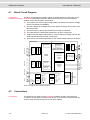
Block Circuit Diagram
56
4.2
Connections
4.2.1
Voltage Supply
4.2.1.1
Voltage Supply Connector
4.2.1.2
Voltage Supply Cable
4.2.2
USB Port
4.2.3
RS 232 Port
4.2.4
CAN Interface
4.2.4.1
CAN Interface Connector
4.2.4.2
CAN Connection Cable
4.2.4.3
CAN low-speed adapter
4.2.5
Trigger Input
4.2.6
Trigger Output
56
57
57
57
59
59
60
62
62
65
66
66
4.3
LED Indicators
66
4.4
Hardware States
67
4.5
Technical Data
4.5.1
General Technical Data
4.5.2
Voltage Supply
4.5.3
CAN Interface
4.5.3.1
Operation of the CAN High-Speed Interface
4.5.3.2
Operation of the CAN Low-Speed Interface
4.5.4
CAN Disturbance Section
68
68
68
68
68
69
69
- II -
Version 2.1
© Vector Informatik GmbH
User Manual CANstress
4.5.5
4.5.6
4.5.7
Table of contents
RS 232 Interface
Trigger Input
Trigger Output
70
70
71
5
CANstress Messages
73
5.1
Overview of CANstress Messages
74
6
FAQ
77
6.1
FAQ Overview
78
7
Appendix A: Address table
85
8
Index
87
© Vector Informatik GmbH
Version 2.1
- III -
User Manual CANstress
Introduction
1 Introduction
In this chapter you find the following information:
1.1
About this user manual
Access helps and conventions
Certification
Warranty
Support
Registered trademarks
© Vector Informatik GmbH
page 6
Version 2.1
-5-
Introduction
1.1
User Manual CANstress
About this user manual
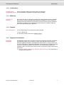
1.1.1 Access helps and conventions
To find information
quickly
The user manual provides you the following access helps:
¼ At the beginning of each chapter you will find a summary of the contents,
¼ In the header you can see in which chapter and paragraph you are ((situated)),
¼ In the footer you can see to which version the user manual replies,
¼ At the end of the user manual you will find an index, with whose help you will
quickly find information.
Conventions
In the two following charts you will find the conventions used in the user manual
regarding utilized spellings and symbols.
Style
Utilization
bold
Blocks, surface elements, window- and dialog names of the
software. Accentuation of warnings and advices.
[OK]
Push buttons in brackets
File | Save
Notation for menus and menu entries
CANstress
Legally protected proper names and side notes.
Source code
File name and source code.
Hyperlink
Hyperlinks and references.
<STRG>+<S>
Notation for shortcuts.
Symbol
Utilization
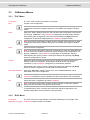
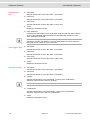
Here you can obtain supplemental information.
This symbol calls your attention to warnings.
Here you can find additional information.
Here is an example that has been prepared for you.
Step-by-step instructions provide assistance at these points.
Instructions on editing files are found at these points.
This symbol warns you not to edit the specified file.
-6-
Version 2.1
© Vector Informatik GmbH
User Manual CANstress
Introduction
1.1.2 Certification
Certified Quality
Vector Informatik GmbH has ISO 9001:2000-12 certification.
Management System The ISO standard is a globally recognized quality standard.
1.1.3 Warranty
Restriction of
warranty
We reserve the right to change the contents of the documentation and the software
without notice. Vector Informatik GmbH assumes no liability for correct contents or
damages which are resulted from the usage of the user manual. We are grateful for
references to mistakes or for suggestions for improvement to be able to offer you
even more efficient products in the future.
1.1.4 Support
You need support?
You can get through to our hotline at the phone number
+49 (711) 80670-200
or you send a problem report to the CANoe-Support.
1.1.5 Registered trademarks
Registered
trademarks
All trademarks mentioned in this user manual and if necessary third party registered
are absolutely subject to the conditions of each valid label right and the rights of
particular registered proprietor. All trademarks, trade names or company names are
or can be trademarks or registered trademarks of their particular proprietors. All rights
which are not expressly allowed, are reserved. If an explicit label of trademarks,
which are used in this user manual, fails, should not mean that a name is free of third
party rights.
¼ Outlook, Windows, Windows XP, Windows 2000, Windows NT are trademarks of
the Microsoft Corporation.
© Vector Informatik GmbH
Version 2.1
-7-
User Manual CANstress
Basics
2 Basics
In this chapter you find the following information:
2.1
Overview of CANstress
CANstress System Components
Functional Features of CANstress
page 10
2.2
COM Server
page 11
2.3
Installation of the CANstress Software
page 12
2.4
Startup of the CANstress Hardware
page 12
2.5
INI Files
VECTOR.INI
CANstress.INI
page 13
2.6
Filename Extensions
page 16
2.7
Keyboard Operations (Shortcuts)
page 16
2.8
Sample Configurations
page 17
2.9
CANstress Online Help
page 19
© Vector Informatik GmbH
Version 2.1
-9-
Basics
2.1
User Manual CANstress
Overview of CANstress
Disturbance of the
CAN bus
With CANstress the user can cause specific and reproducible disturbances of the
CAN bus, its physical properties and the logical level (recessive or dominant).
CANstress offers the following capabilities:
¼ Forcing of recessive or dominant bus levels
¼ Simulation of difficult-to-troubleshoot faults
¼ Disturbance of specific messages
¼ Manipulation of the bit fields of CAN messages
CANstress variants
The following CANstress variants are available:
¼ CANstressD (Digital)
¼ CANstressDR (Digital and Resistor network)
2.1.1 CANstress System Components
Hardware
CANstress consists of a robust hardware module and the CANstress software that is
used to configure the CANstress hardware.
The CANstress hardware is fed directly into the CAN bus line to be disturbed using
the supplied CAN connection cable. The CANstress hardware is connected to the PC
via the serial RS-232 or USB port.
With few CAN nodes and a resulting small terminating resistor, you probably need the
included CAN low-speed adapter, when operating CAN low-speed networks. Place
this connector between the CAN socket on the CANstress disturbance module and
the CAN connector cable.
2.1.2 Functional Features of CANstress
Initiate disturbances
Digital disturbances can be initiated on the CAN bus with CANstressD and CANstressDR. The disturbances that CANstress forces on the CAN bus are userdefinable sequences of dominant and/or recessive disturbance pulses. The
disturbance pulses can be defined on both the bit level and BTL level.
A trigger is used to initiate the disturbances. The following trigger types are available:
¼ Bit field trigger
¼ Start of Frame
¼ Error Frame
¼ End of Frame / Bus Idle
¼ External
¼ Software
An external output (e.g. for an oscilloscope connection) can also be triggered by
these trigger types.
Besides disturbing on the bit level, it is also possible to disturb on the BTL level. In
this case the smallest specifiable disturbance does not consist of a complete bit time,
rather just one BTL cycle. This makes it possible to partially disturb a bit.
- 10 -
Version 2.1
© Vector Informatik GmbH
User Manual CANstress
Basics
The following disturbance modes are available:
¼ Unlimited number of disturbances
¼ Limited number of disturbances
¼ Continuous disturbance (while trigger)
¼ Continuous disturbance (until stop)
¼ Continuous disturbance (time limited)
Bit triggers and disturbance messages may be configured using the symbolic
identifiers from a CANdb database.
In addition to the capabilities named above, CANstressDR also has a resistor network
and capacitor network with which analog disturbances can be generated on the CAN
bus. For example, this makes it possible to simulate line losses in the network and
different bus lengths.
With CANstressDR, if a continuous disturbance is active the resistor network can be
modified interactively. This allows the user to study gradual changes to the physics of
the bus.
2.2
COM Server
Controlling from
external programs
With the help of the COM Server you can control CANstress from external programs.
External programs are not just understood to be applications; scripts also come under
consideration. Certainly the most well-known script and programming languages
available to you for this purpose include: VBScript, JScript, Perl, VBA, Visual Basic,
Delphi and C/C++:
¼ VBScript
¼ Jscript
¼ Perl
¼ VBA
¼ Visual Basic
¼ Delphi
¼ C/C++
Info: Using an automation interface this product may be integrated as a subsystem in
higher-level systems. If you are using such automation interfaces the company Vector
Informatik GmbH does not provide any additional guarantees or assume any liability
for correcting errors or refunding the sales price, since we have no influence on
possible faulty implementations of the higher-level system.
In such cases our disclaimer is not displayed when CANstress is called by a script (or
similar).
Cross reference: You can find detailed information of the COM server in the online
help.
© Vector Informatik GmbH
Version 2.1
- 11 -
Basics
2.3
User Manual CANstress
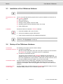
Installation of the CANstress Software
Note: You need administrator rights to install the software!
Requirements of the
PC
Your PC must fulfil the following requirements to permit installation and execution of
the CANstress software:
¼ IBM-compatible PC
¼ Processor: Pentium 2
¼ Working memory (RAM): at least 512 MB
¼ Operating system: Microsoft Windows 2000, XP or Vista
¼ USB or RS232 port
Installation
Proceed as follows to install the CANstress software:
1. Insert the installation CD in your CD drive.
2. Call up the installation program SETUP.EXE.
3. Folgen Sie den Anweisungen des Installationsprogramms.
Note: The language of the menus and dialogs can be switched at any time after the
installation ( See VECTOR.INI on page 13)
2.4
Startup of the CANstress Hardware
Connections:
The following connections must be made for startup:
Connection to the PC ¼ Connection via USB port:
With the included USB cable, which has a four-pole connector for the connection
to CANstress on one side, a connection to the PC is established.
¼ Connection via serial RS-232 port:
The RS 232 control interface of the CANstress hardware is connected to an
available COM port on the PC using the DB-9 extension cable provided. If the PC
port is not equipped with a 9-pin connector, rather with a 25-pin connector, then a
9-to-25 pin adapter should be added to the PC end of the cable.
Connection to CAN
The bus is opened at any suitable point, preferably at a CIA-conformant DB-9
connection; this is where the CAN adapter cable is fed into the bus. The 15-pin
connector of the adapter cable is then plugged into the CAN port of the CAN-stress
hardware.
Connection to the
current supply
A supply voltage of 8 to 40 VDC is fed to the CANstress hardware's supply connector
using the cable provided or over a customer-specific cable.
- 12 -
Version 2.1
© Vector Informatik GmbH
User Manual CANstress
2.5
Basics
INI Files
Oveview
INI files are usually ASCII text files that contain configuration options for application
programs.
The names in square brackets (for example [Language] in the INI file
VECTOR.INI) refer to individual sections of the INI file in which the options can be
configured.
Comment lines in the INI files are identified by // at the beginning of the line, and they
describe the available options.
Note: The sequence of sections within a INI file and the sequence of options within a
section are irrelevant.
Within INI files upper/lower case font is irrelevant.
The INI files are located in the %COMMONAPPDATA%\Vector\CANstress directory.
By default with Win2000 and WinXP %COMMONAPPDATA% corresponds to <drive of
windows installation>\Documents and Settings\All Users. With
Windows Vista %COMMONAPPDATA% corresponds to <drive of windows
installation>\Program Data\Vector\CANstress.
The Vector.INI file can only be changed with administrator rights.
Change settings
Proceed as follows to change the options in a INI file:
1. Open the INI file with an ASCII editor.
2. Change the options as desired. For example, if you wish to change the language
of menus and dialogs in VECTOR.INI you would replace the numeric language
identifier entered in the line Country= in the section [Language] with the
identifier for the desired language.
Example:
The following entry causes menus and dialogs to appear in English:
[Language]
Country=01
3. Save the INI file and close the editor.
Note: If CANstress was opened during editing, you must exit CANstress and then
reopen it to have the new configuration take effect.
2.5.1 VECTOR.INI
Settings
The following options can be configured in VECTOR.INI:
¼ Language of the menus and dialogs (section [Language], line Country= )
¼ Path in which the CANdb Editor is installed (section [CANdb], line Path= )
© Vector Informatik GmbH
Version 2.1
- 13 -
Basics
User Manual CANstress
Note: If the language of your version of Windows does not agree with the language
set for CANstress some dialogs and buttons will appear in the language of your
Windows version.
For example, if you have set English as the language for CANstress under a German
version of Windows, the German "Öffnen" ("Open") dialog appears, since Windows
resources are referenced here.
2.5.2 CANstress.INI
Settings
The following options can be configured in CANstress.INI:
¼ Last opened configuration (section [AppInfo], line LastConfig= )
¼ Serial port of the computer to which the CANstress hardware is connected
(section [Local Settings], line ComPort= )
¼ Baudrate at which communications occur between the computer and the
CANstress hardware (section [Local Settings], line BaudRate= )
¼ List of last opened configurations (section [Recent File List])
Maximum
disturbance voltage
This entry only applies to devices of the type CANstressDR; it does not affect devices
of the type CANstressD.
In the file CANstress.ini there is the following INI entry:
[Hardware]
ExactDistVoltage=12
ExactDistVoltage gives the maximum disturbance voltage that is fed or may be
fed to the CANstress hardware. The default entry is 12 (Volt).
The value given as ExactDistVoltage is used to calculate loads of resistors R_H,
R_HL and R_L on the Analog Board and to decide wither your selected resistor
values may be transferred to the hardware, or whether they could potentially result in
hardware damage. (See also “Resistor validation“)
If you feed in a different disturbance voltage please observe the following instructions:
¼ The maximum allowable disturbance voltage that may be applied to the hardware
is 40 V.
¼ The disturbance voltage you are applying must be entered in the INI entry
ExactDistVoltage!
[Hardware]
ExactDistVoltage=12
Note: You should never specify a disturbance voltage in the INI entry that is lower
than the voltage you actually apply to the device! Otherwise the hardware might be
permanently damaged! Make sure that the INI entry ExactDistVoltage is always
configured correctly.
- 14 -
Version 2.1
© Vector Informatik GmbH
User Manual CANstress
Resistor validation
Basics
This entry only applies to devices of the type CANstressDR; it does not affect devices
of the type CANstressD.
The resistor settings are validated before the configuration that is set at the CANstress user interface is downloaded to the hardware. This involves checking whether
the current settings may be transferred to the hard-ware, or whether they could result
in potential hardware damage. If there is a risk of hardware damage, transfer of the
configuration to the hardware is aborted.
To ensure that the validation process will detect potential hardware damage and prevent transfer of the configuration that could result in damage, the voltage applied as
the disturbance voltage must be entered in the INI entry ExactDistVoltage!
If you do not make any changes to the hardware the 12 V supply voltage is also used
as the disturbance voltage. Therefore, the entry ExactDistVoltage=12 already
has already been made in CANstress.INI.
Note: If you make changes to the CANstress hardware and feed in a disturbance
voltage that is different from the delivered state, you must enter it in the
ExactDistVoltage entry of the CANstress.INI file! Under no circumstances should
the disturbance voltage you apply be greater than the disturbance voltage given in
ExactDistVoltage! Otherwise the hardware could be permanently damaged!
Make sure that the INI entry ExactDistVoltage is always set correctly.
Note: Resistor validation is performed immediately before transferring the
configuration to the hardware, if resistor R_H is connected to V_D+ and R_L is
connected to V_D- (or reversed) and both R_H and R_L are connected.
In resistor validation the resistors R_H, R_HL and R_L are subjected to a check.
First, a determination is made to determine the individual resistances in a resistor
matrix (see Technical data of the CAN disturbance module) of which the resistor is
composed.
Afterwards a calculation is made to determine how much power is dissipated by the
individual resistors when the voltage specified in ExactDistVoltage is applied. If
the power dissipation at an individual resistor is greater than the maximum allowable
loading for the individual resistor, this is recognized as an unallowable state, and
transfer of the configuration to the hardware is not permitted.
Display of the CAN
baudrate and the
CAN bus type
After the disturbance start, the toolbar displays:
¼ which CAN baudrate is set
¼ which CAN bus type (high-speed, low-speed) is used. The CAN bus type is
acquired from the information of the used CAN interface.
This information is used to check whether suitable CAN settings are used.
The display of this information is limited to a defined time and can be controlled via an
entry in the CANstress.ini file:
[AppInfo]
// Period of time (in ms) for which the CAN information is
displayed in the toolbar.
ShowCanInfo=5000
Mit ShowCanInfo=0 lässt sich die Anzeige abschalten.
© Vector Informatik GmbH
Version 2.1
- 15 -
Basics
2.6
User Manual CANstress
Filename Extensions
A filename extension refers to the three characters located after the dot following the
file name. The filename extension identifies the file type.
2.7
- 16 -
Filename extension
File type
CNT
Table of contents for Help files (Contents)
CST
CANstress configuration
DBC
Database (Data Base for CAN)
DLL
Runtime library (Dynamic Link Library)
EXE
Executable Program
CHM
Help file (Help)
INI
File with configuration options
Keyboard Operations (Shortcuts)
Key(s)
Operation
Command
<Ctrl>+<O>
Opens a configuration.
"Open"
("File" menu)
<Ctrl>+<N>
Creates a new configuration.
"New"
("File" menu)
<Ctrl>+<S>
Saves the active configuration.
"Save"
("File" menu)
<Esc>
Closes the active dialog without
accepting the changes. (Corresponds
to activation of the [Cancel] button or
[Close].)
If trigger and disturbance systems are
activated:
Deactivates the trigger and
disturbance systems.
"Stop"
("Disturbance" menu)
<F1>
Calls CANstress help for the active
dialog or selected command.
If CANstress help is active:
Calls Help texts containing information
on using and configuring Help.
<F3>
Selects the external output selection
list in the toolbar.
In this list you can select the trigger for
the external output.
<F4>
Back to the active window.
With this shortcut you can (re)set the
focus on the active window, after
selecting the trigger for the disturbance
or the external output (with the aid of
<F2> or <F3>).
Version 2.1
© Vector Informatik GmbH
User Manual CANstress
2.8
Basics
Key(s)
Operation
Command
<F8>
Initiates a software trigger or
activates/deactivates software level
triggering.
"Trigger"
("Disturbance" menu)
<F9>
Establishes a connection to the CANstress hardware and activates the
trigger and disturbance systems.
"Start"
("Disturbance" menu)
<F10>
Activates the main menu bar.
<Alt>+<F4>
Closes the active configuration and
exits CANstress.
<Alt>+Space
Opens the System menu of the CANstress program window.
Alternatively the System menu could
also be opened by double clicking the
System icon.
<Ctrl>+<Tab>
Activates the next page of the
CANstress program window.
The menu pages can also be activated
with the commands of the "View"
menu.
<Ctrl>+<Shift>+
<Tab>
Activates the previous page of the
CANstress program window.
The menu pages can also be activated
with the commands of the "View"
menu.
<Tab>
In pages or dialogs:
Selects the next user control element
(Control).
<Shift>+<Tab>
In pages or dialogs:
Selects the previous user control
element (Control).
Spacebar
In pages or dialogs:
Activates or deactivates an option box.
Arrow keys
If an option box is selected in pages or
dialogs:
Selects the next option.
"Exit"
("File" menu)
Sample Configurations
Configurations:
The following sample configurations are included with the CANstress software:
Disturb-SOF-Bit.cst
With this configuration the Start Of Frame Bit is disturbed by a recessive bit.
Disturb-SOF-BitWith-BTL.cst
With this configuration the 1st BTL cycle in the Start Of Frame Bit is forced to a
recessive level.
Disturb-AbsDataID.cst
With this configuration the message ABSData (from the DBC database motbus.dbc)
is disturbed. CANstress overwrites the 11th bit in the ID by a dominant bit.
© Vector Informatik GmbH
Version 2.1
- 17 -
Basics
User Manual CANstress
Error-Frame-OnSOF.cst
With this configuration an Error Frame is triggered by a Start Of Frame.
Error-Frame-OnAbsData-ID.cst
With this configuration an Error Frame is triggered once when the ID of the message
ABSdata (from the DBC database motbus.dbc) occurs.
Trigger-ExternOutput-On-ErrorFrame.cst
With this configuration the external trigger output is set to the High level when an
Error Frame occurs, e.g. to trigger an external device.
Error-Frame-OnExtern-Trigger.cst
With this configuration an Error Frame is initiated as soon as a Low->High edge
occurs at the external trigger input.
Disturb-ACK-onID.cst
With this configuration the dominant bit in the ACK slot - which receivers of the
message ABSdata (from the DBC database motbus.dbc) send out as
acknowledgment that the message was received - is disturbed recessively.
Disturb-ACK-onDifferent-ID.cst
With this configuration, for all transmitted messages of the node ABS (from the DBC
database motbus.dbc) the dominant bit in the ACK slot - which receivers of these
messages send out as confirmation that the message was received - is disturbed
recessively. The Bit Field Trigger condition for this case is obtained by starting the
"Selection of Messages" dialog on the "Bit Field Trigger" page and selecting all Tx
messages of the node ABS by clicking and simultaneously pressing the <CTRL> key.
After pressing [OK] the resulting trigger condition is constructed and displayed for the
selected messages (ABSdata, WheelInfo, WheelInfoIEEE). (Afterwards the ACK slot
must be cleared to ensure that the trigger condition also ends before the ACK slot).
Multi-Disturb-WithPause.cst
With this configuration an Error Frame is placed on the bus when a Start Of Frame is
detected. This occurs five times within one disturbance cycle. Afterwards the bus is
left undisturbed for 10 ms. In this time period the bus can recover, and the error
counters of the nodes are decremented by correct receipt and transmission of
messages.
ABSdata-Bus-Off.cst
With this configuration the sender of the message ABSdata is intentionally put into the
Bus-Off state.
Trigger-On-CertainDatafield.cst
With this configuration both the disturbance and the external trigger output are
triggered as soon as a message occurs which contains '0011 xx00' in its 3rd data
byte (i.e. the 5th and 6th bits can have any arbitrary contents). This trigger condition
can essentially only be fulfilled by messages whose DLC>=3.
Send-Msg-WithCRC-Error-On-BusIdle.cst
With this configuration, during Bus-Idle a message is sent out whose last bit in the
CRC sequence is corrupted to '1' instead of '0'. This permits testing of whether a
receiver detects this CRC error.
The disturbance sequence was created by starting on the "Disturbance" menu page
of the Disturbance Sequence Wizard, pressing the [Message] button in the
"Disturbance Message" dialog that opens and selecting the message ABSdata by
double clicking it. Before exiting the dialog with [OK] the last bit of the CRC sequence
was also changed from '0' auf '1' and the CRC delimiter was cleared.
- 18 -
Version 2.1
© Vector Informatik GmbH
User Manual CANstress
2.9
Basics
CANstress Online Help
CANstress provides a comprehensive online Help function which can be called from
the "Help" menu, the [Help] button or the <F1> key.
Cross reference: If you choose the "Using Help" command ("Help" menu) or press
the <F1> key while CANstress online Help is active, you get information on using and
configuring the online Help function.
© Vector Informatik GmbH
Version 2.1
- 19 -
User Manual CANstress
CANstress Software
3 CANstress Software
In this chapter you find the following information:
3.1
CANstress Program Window
Title Bar
Main Menu Bar
Toolbar
Status Bar
page 23
3.2
Pages
"Bit Field Trigger" Page
"Other Trigger" Page
"Disturbance" Page
"Analog Disturbance" Page
page 25
3.3
CANstress Menus
"File" Menu
"Edit" Menu
"View" Menu
"Disturbance" Menu
"Options" Menu
"Help" Menu
page 35
3.4
CANstress Dialogs
"CAN Interface" Dialog
"Channel Configuration" Dialog
"External Output" Dialog
"Connection Parameters" Dialog
"Disturbance Sequence for Bit Field Trigger" Dialog
"Disturbance Message" Dialog
"Disturbance Sequence" Dialog
"Error Frame" Dialog
"Databases" Dialog
"Selection of Messages" Dialog
"Hex/Dec input" Dialog
"About CANstress" Dialog
page 38
© Vector Informatik GmbH
Version 2.1
- 21 -
CANstress Software
User Manual CANstress
3.5
Trigger Sources
Triggering on CAN Bit Fields (Bit Field Trigger)
Triggering on Start of Frame
Triggering on Error Frame
Triggering on End of Frame / Bus Idle
Triggering by External Input
Triggering by Software
Triggering by "Continuous trigger"
Triggering "Like disturbance"
page 45
3.6
Disturbances (Disturbance Actions)
Time Point of Disturbance
External Disturbance Voltage
page 49
3.7
Disturbance Mode
'Unlimited Number of Disturbances' Disturbance Mode
'Limited Number of Disturbances' Disturbance Mode
'Continuous Disturbance (while trigger)' Disturbance Mode
'Continuous disturbance (until stop)' disturbance Mode
'Continuous disturbance (time limited)' disturbance Mode
page 50
3.8
Disturbance Sequence Wizard
page 51
3.9
Configuration
page 51
3.10 Establishing a Connection
Via USB port
Via serial RS-232 port
page 52
3.11 Working with CAN Databases
page 53
- 22 -
Version 2.1
© Vector Informatik GmbH
User Manual CANstress
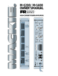
3.1
CANstress Software
CANstress Program Window
Screenshot
3.1.1 Title Bar
Display of the
configuration
The title bar of the CANstress program window contains, in addition to the CANstress
system symbol, the name of the currently active CANstress configuration.
3.1.2 Main Menu Bar
Basic functions
The main menu bar is located directly below the title bar on the CANstress program
window.
3.1.3 Toolbar
Quick access to
commands
The icons arranged on the toolbar allow the user quick access to frequently used
commands. The toolbar is located beneath the menu bar in the CANstress program
window. Clicking an icon causes the associated command to be executed.
© Vector Informatik GmbH
Version 2.1
- 23 -
CANstress Software
User Manual CANstress
Symbol
Command
"New file" ("File" menu)
"Open file" ("File" menu)
"Save" ("File" menu)
"Start" ("Disturbance" menu)
"Stop" ("Disturbance" menu)
"Trigger" ("Disturbance" menu)
Display of the current Next to the icons the toolbar contains a box which displays the current disturbance
disturbance state
state, and list boxes for selecting the trigger source for the disturbance system and
the external output.
Element
Explanation
Box for user visualization of the momentary
disturbance state. As soon as disturbances are
generated information on the disturbances appears
here.
The trigger source for the disturbance system can be
selected here.
The trigger source for the external output can be
selected here.
Dist-Info
(upper line)
In the 'Limited number of disturbances' and 'Unlimited number of disturbances'
disturbance modes, appearing instead of "Dist-Info" is the number of disturbances
per-formed. After the slash is the total number of disturbances to be performed. (The
total number of disturbances to be performed is calculated as follows: Number of
disturbances per disturbance cycle * Number of disturbance cycles.) Displayed in the
'Continuous disturbance' disturbance mode is how often the continuous disturbance
was switched on and off.
Rep-Info
(lower line)
n the 'Limited number of disturbances' mode, appearing instead of "Rep-Info" is the
number of disturbance cycles performed. After the slash is the total number of
disturbance cycles to be performed. In the 'Unlimited number of disturbances' and
'Continuous disturbance' modes '0/1' always appears here, since in these two modes
there is only one disturbance cycle which however is never run through completely.
3.1.4
Status Bar
The status bar is located along the lower border of a window.
Inforamtion about
command
- 24 -
If the mouse pointer is located above an icon in the CANstress program window, or if
a command is selected, then a brief description of that command appears in the left
status bar box.
Version 2.1
© Vector Informatik GmbH
User Manual CANstress
CANstress Software
Connection status:
Displayed in the middle box is information on the current connection status to the
CANstress hardware:
Disconnected
There is no connection between the CANstress hardware and the CANstress
software.
Connected at ...
baud
CANstress hardware and CANstress software are connected; communication occurs
at the indicated baud rate.
Transmit at new
baud rate ...
If the baud rate was changed in the "Connection Parameters" dialog while a
connection existed between the hardware and software, this status line appears
briefly. The CANstress software attempts to establish a connection at the changed
baud rate.
Connect over COM
... at ... baud
The CANstress software attempts to establish a connection to the CANstress
hardware over the specified serial port and at the indicated baud rate.
Connected via USB
with ...
With an existing connection via USB the unit number of the connected CANstress unit
is displayed.
Connection layer
ready
The connection layer between the CANstress software and CANstress hardware is
ready to establish a connection.
Key status
The boxes on the right side of the status bar offer information on the status of the
user-selectable keys:
¼ "INS"
The <Ins> key is activated.
¼ "NUM"
The <Num> key is activated ('Num Lock' LED illuminates).
3.2
Pages
3.2.1 "Bit Field Trigger" Page
Bit field trigger
Defined here are the contents of bit fields for triggering on message contents. For this
there various trigger bits are available.
Frame format
The message format (Standard or Extended) is set here.
Chosse message
After activating the [Message] button, the message on which to trigger can be
selected in the "Selection of Messages" dialog.
Since the data bytes of a selected message are not prescribed, those input fields and
the CRC Sequence input field are filled with don't care bits.
If you wish to trigger on a group of CANdb messages, it is also possible to make a
multiple selection in the "Selection of Messages" dialog. This involves combining
these messages with one another to come up with a resulting message, whereby the
bit positions that do not agree are given a don't care bit.
Example: Message 1 begins with '1101....'. Message 2 begins with '1100...'. In this
case the first four bits of the resulting message yield '110x' in order to satisfy the
trigger condition for both '1100' and for '1101'.
© Vector Informatik GmbH
Version 2.1
- 25 -
CANstress Software
User Manual CANstress
Note: The [Message] button is only active if one or more DBC databases were
associated to the active configuration. (Use the "Associate database" command
("File" menu) to associate DBC databases to the active configuration.
Bit input fields
The input boxes in the Bit Field Trigger window can essentially be filled with '0'
(dominant), '1' (recessive) or 'x' (don't care). Selected bits can be edited together with
commands of the "Edit" menu or commands of the popup menu.
The end of the trigger condition is defined by the last specified bit. For example, if the
input field for the CRC sequence only contains one bit, the trigger condition also ends
with this bit.
In evaluating the bit field trigger condition by the hardware, all bits up to the last
specified bit are used in the comparison with the received bit sequence (from which
the stuff bits were removed) - even if the last bits were specified as don't care bits.
Consequently, the earliest the disturbance sequence can be initiated is after the last
bit of the trigger condition (see also "Disturb any stuff bit" in this context).
The bit field trigger condition is satisfied if the received bit sequence agrees with the
care bits ('0' or '1') in all bit positions.
Note: The bit field trigger condition that is given to the hardware is a combination of
all editable input fields: e.g. if a Data Length Code (DLC) is specified as '0001', then
only one data field is editable. Only this field is used for the trigger condition, while the
seven remaining non-editable data fields are not considered in triggering (even if they
are not empty).
For specific edit fields the input of values via the "Hex/Dec input" dialog is possible
now.
Automatic filling or
clearing of input
fields
All bits from the beginning of a message to the last bit of the trigger condition must be
specified. Therefore, input fields which lie 'before' the end of the trigger condition but
are not completely filled are supplemental filled up with don't care bits as soon as the
cursor disappears from the input field in which the last entry was made. 'Before'
means that from the receiver's perspective the bits belonging to this input field would
be received before the end of the trigger condition.
For example, if an empty bit field trigger condition is entered beginning with the DLC,
it is assumed that the previous bits do not play any role in the formulation of the
trigger condition, and accordingly the associated input fields are filled with don't care
bits (with the exception of the IDE bit input field).
Since the trigger condition is ended by the last specified bit, all input fields that come
'after' an incompletely filled input field are cleared. In this context 'After' means that
from the receiver's perspective the bits associated with these input fields would be
received after the last bit of the trigger condition.
For example, if the input field for the DLC was not completely filled, among other
things all subsequent input fields for data bytes would be emptied of entries.
Disturb possible stuff Essentially it is possible for a stuff bit to occur after the specified trigger condition. The
bit
"Disturb possible stuff bit" option can be used to decide whether or not a stuff bit
occurring after the trigger condition should be disturbed.
For example, if you only wish to disturb the dominant RTR bit of a CAN data frame in
Standard format with a recessive disturbance bit, you would use only don't care bits
for the ID as the trigger condition and also deactivate the "Disturb possible stuff bit"
option. Otherwise the disturbance sequence (consisting of only one bit) would only
disturb a stuff bit if one occurred.
- 26 -
Version 2.1
© Vector Informatik GmbH
User Manual CANstress
CANstress Software
On the other hand, if you wish for example to intentionally disturb the stuff bit that
occurs if the ID of a message begins with five recessive bits, you would specify five
recessive bits ('1') in the ID input field as the trigger condition and activate the
"Disturb possible stuff bit" option.
Special input fields:
IDE
The input field for the IDE bit has some special characteristics. These are related to
its role in specifying whether the hardware interprets the received bit stream as a
message in Standard format or as a message in Extended format.
In Standard format the IDE bit can only assume the values '0' (dominant) or 'x' (don't
care). If 'x' is entered for the IDE bit, it is not possible for the hardware to properly
interpret the bit stream beyond the IDE bit. For this reason, when a don't care IDE bit
is entered it is also not possible to specify a bit field trigger condition that goes beyond the IDE bit. This also applies to messages in Extended format.
For the same reasons, in Extended format the IDE Bit may only assume the values '1'
(recessive) or 'x' (don't care).
RTR
Here the user defines whether triggering should occur on Data frames (dominant RTR
bit) or on Remote frames (recessive RTR bit) or on both types (don't care RTR bit).
If a recessive bit is specified in the "RTR" input field, the input fields for the data bytes
are disabled for user input, since no data bytes are sent with a Remote frame, and
they also may not be used in the evaluation of the trigger condition.
If a don't care bit is specified in the "RTR" input field, all data bytes that result from
evaluation of the DLC input field are enabled for user input. When don't care bits are
entered in the input fields for data bytes, triggering occurs on both Data frames and
Remote frames. However, if a care bit is given in a data byte the hardware only
triggers on messages which also contain this care bit, and therefore there is no
triggering on Remote frames.
DLC
Here the user specifies how many data byte input fields are editable. If a valid value is
entered (i.e. a DLC from 0 to 8) in the DLC input field, then the relevant input fields for
the data bytes are enabled or disabled accordingly. For example, if a DLC of 1 is
entered (i.e. '0001') then the input field for the 1st data byte is enabled and all others
are disabled for user input.
When don't care bits are entered in the DLC input field, the maximum possible DLC is
calculated from these bits and the data byte input fields are enabled or disabled
accordingly.
Note: If four don't care bits are entered in the DLC input field, and the eight edit-able
input fields for the data bytes are also filled with don't care bits, then the hardware
triggers on messages that have 0 to8 data bytes.
On the other hand, if four don't care bits are entered in the DLC input field, and a care
bit is entered in the 8th editable data byte, the hardware only triggers on messages
that actually have this care bit in the 8th data byte. That is, in this case triggering
never occurs on messages having fewer than eight data bytes!
If an invalid DLC is specified in the DLC input field (e.g. '1111') no further
(meaningful) support can be provided for displaying the proper data fields. In this
case all eight data fields are enabled for user input (since this is a case of a DLC > 8).
CRC Sequence
If all input fields up to the input field for the CRC sequence are filled without don't care
bits, it is possible to have this field automatically filled with the appropriate CRC code.
To do this, place the cursor over the "CRC Sequence" input field and then choose the
"CRC Sequence" command ("Edit" menu). Alternately the same command could be
accessed from the popup menu.
© Vector Informatik GmbH
Version 2.1
- 27 -
CANstress Software
User Manual CANstress
3.2.2 "Other Trigger" Page
Remaining triggers:
Located here are the configuration fields for the remaining triggers.
Error flag
The number of dominant bits n (n=6 to 12) for an Error frame's error flag specifies
how many dominant bits must occur in the error flag to cause triggering.
For n=6 triggering occurs as soon as an Error frame is detected. For n=12 triggering
occurs when the superimposed error flags of different network nodes yield an error
flag with 12 dominant bits (see also: Triggering on Error Frame on page 46 )
End of Frame/BusIdle trigger
The number of recessive bits n (n=8 to 18) specifies how many recessive bits must
follow after a dominant bit (dominant ACK slot, see below) to cause triggering. For
n=8, for example, triggering occurs after a message's End of Frame (n=8: One
recessive bit of the ACK delimiter + seven recessive bits of the End of Frame),
provided that there is more than one node in the network: Only if there are a receiver
and a sender in the network the sender's recessive bit in the ACK slot is overwritten
by a dominant bit by the receiver.
For the case where only one node (sender) exists in the network, it can only be
assured that the bus is in the Bus Idle state after 17 consecutive recessive bits.
Explanation: Since no dominant ACK slot occurs the following is possible: Up to 4
recessive bits (at the end of the CRC sequence) + 1 recessive bit (CRC delimiter) + 1
recessive bit (ACK slot!) + 1 recessive bit (ACK delimiter) + 7 recessive bits (End of
Frame) + 3 recessive bits (Intermission) yield 17 recessive bits in succession.
In this case bit field triggering could also be used.
(See also FAQ Overview on page 78: How do I trigger on End of Frame if there is
only one node (Sender) in the network?)
In a normal network with sender(s) and receiver(s), on the other hand, it can be
assured after 11 consecutive recessive bits that the bus is in the Bus Idle state. After
1 dominant bit (ACK slot) there follows 1 recessive bit (ACK delimiter) + 7 recessive
bits (End of Frame) + 3 recessive bits (Intermission).
(See also: Triggering on End of Frame / Bus Idle on page 47)
External input
With the external input it is possible to define whether the input should be used as an
external trigger or as a trigger enable signal.
When used as an external trigger the user can choose whether the input should be a
Level trigger (with LOW or HIGH level) or an Edge trigger (with triggering on the transition from LOW->HIGH or HIGH->LOW).
When used as a trigger enable signal, the user can decide whether, when a trigger
condition is satisfied, there must also be a low (LOW) or high (HIGH) voltage level at
the input to permit triggering.
(See also: Triggering by External Input on page 47)
Software trigger
With the software trigger the user can configure whether it should act as an Edge
trigger or as a Level trigger.
If the software trigger is used as an Edge trigger, the trigger icon on the toolbar
behaves like a conventional icon. When used as a Level trigger the icon appears
alternately as 'not pressed' and as 'pressed'. Similarly, in this case a or no .
(See also: Triggering by Software on page 47)
- 28 -
Version 2.1
© Vector Informatik GmbH
User Manual CANstress
Continuous trigger
CANstress Software
The Continuous trigger is triggered immediately after disturbance start
(Disturbance|Start).
¼ With the "Unlimited duration" option, the continuous trigger will only be switched
off when the disturbance ends (Disturbance|Stop).
¼ With the "Duration" option, you can set the time after which the continuous trigger
will be ended automatically. The time-controlled continuous trigger can only be
ended prematurely by selecting Disturbance|Stop.
Note: The trigger sources "Continuous trigger" and "Software" cannot be used
simultaneously since the continuous trigger is already implemented in the program as
a software trigger.
For the Continuous trigger, the "as trigger enable" setting of the external input will not
be considered or used.
3.2.3 "Disturbance" Page
Disturbance
The disturbance mode is selected here (see Disturbance Mode on page 50) and the
disturbance sequence is defined.
Disturbance modes:
For the disturbance bits, various disturbance states can be defined.
Unlimited number of
disturbances
In the 'Unlimited number of disturbances' disturbance mode, a disturbance is executed for each trigger event. The total number of triggered disturbances is unlimited.
Limited number of
disturbances
In the 'Limited number of disturbances' disturbance mode, the number of
disturbances n within a disturbance cycle is limited. After n disturbances have been
executed a configurable pause p is inserted, unless there is only a single disturbance
cycle. The number of disturbance cycles to be performed is also configurable.
Continuous
disturbance (while
trigger)
In the 'Continuous disturbance (while trigger)' disturbance mode a disturbance is only
executed during the time period in which the trigger condition is satisfied. For this
reason this disturbance mode is only advisable for Level triggering (software trigger
with Level triggering or external trigger with Level triggering).
Continuous
disturbance (until
stop)
The 'Continuous disturbance (until stop)' disturbance mode is an expansion of the
Continuous disturbance disturbance mode. Here the bus with a configurable
disturbance mode (dominant, recessive or analog) can be disturbed continuously too.
The disturbance begins with Disturbance|Start and continues until
Disturbance|Stop.
Continuous
disturbance (timelimited)
The 'Continuous disturbance (time-limited)' disturbance mode is an expansion of the
Continuous disturbance disturbance mode. In addition to a disturbance mode
(dominant, recessive or analog), a duration for the disturbance can be selected. Upon
occurrence of a trigger event, the continuous disturbance will be placed on the bus for
the specified duration.
Disturbance type for
continuous
disturbance
The disturbance types permitted for the continuous disturbance are dominant,
recessive or (in the DR variant) analog disturbance. The disturbance lasts as long as
the trigger condition is satisfied.
Disturbing with
limited number of
disturbances
When disturbing with a limited number of disturbances the user can set the number of
disturbances n (n=1 to 255) per disturbance cycle. For the number of disturbance
cycles m the user can set a value between 1 and 65535 or infinite. The Infinite value
(shown in the display as 'inf') may be set by entering an alpha character or by
decrementing the number of disturbance cycles.
© Vector Informatik GmbH
Version 2.1
- 29 -
CANstress Software
User Manual CANstress
If more than one disturbance cycle should be executed, the user can also configure a
pause p between 1 ms and 65535 ms, which is inserted after n disturbances have
elapsed. During this pause no trigger conditions are evaluated (for the disturbance),
and therefore no disturbance is triggered.
Disturbance
sequence
The disturbance sequence is composed of a sequence of disturbance states. The
user may enter the following values for disturbance states: '0'(dominant),
'1'(recessive), 'u'(undisturbed) and (in the DR variant) 'a'(analog). Using the "Edit"
menu or the context-sensitive menu, the appropriate bit state for marked bits can be
selected.
Depending on whether the selected resolution is BTL cycles or bit times, one
disturbance state refers either to the duration of one BTL cycle or the duration of one
bit time.
The length of the disturbance sequence may assume a value n where n=1 to 2048.
The analog disturbance state is configured on the "Analog disturbance" page.
The Undisturbed disturbance state is not actually a disturbance state, since it does
not influence the state on the bus. Nevertheless it is needed for example to intentionally shift the start of the disturbance by n physical bits or BTL clock cycles, where n is
the number of undisturbed disturbance states at the beginning of the disturbance
sequence (FAQ Overview on page 78:How can triggering of a disturbance be
delayed?).
Cross reference: The Disturbance Sequence Wizard provides support in creating
disturbance sequences ("Disturbance Sequence for Bit Field Trigger" Dialog on page
41, "Disturbance Message" Dialog on page 42, "Disturbance Sequence" Dialog on
page 42, "Error Frame" Dialog on page 43)
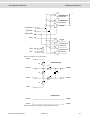
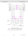
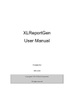
3.2.4 "Analog Disturbance" Page
Note: The "Analog disturbance" page is only available with CANstressDR!
Analog disturbance
The resistor and capacitor network for analog disturbance pulses is defined here.
Analog disturbance pulses may be caused by the following in a real CAN network:
¼ Short circuits
¼ Isolation faults
¼ Poor contacts
The Capacitor C_HL acts in opposition to the resistances at the disturbance start. Its
effect ends with the disturbance stop.
The Resistances act only as long as an analogous disturbance state (‘a’ in the
disturbance result) is on the bus.
The following disturbance parameters may be used to configure the disturbance
state:
¼ R_HL for simulating contact resistances between wires
(e. g. isolation faults, humidity, short circuits)
¼ R_H for simulating contact resistances to disturbance voltages
¼ R_L for simulating contact resistances to disturbance voltages
- 30 -
Version 2.1
© Vector Informatik GmbH
User Manual CANstress
CANstress Software
¼ R_SH for simulating length resistances in wiring
(e. g. poor contacts or line breaks)
¼ R_SL for simulating length resistances in wiring
(e.g. poor contacts or line breaks)
¼ C_HL for simulating longer bus lines at low baudrates
(only makes sense for Low-Speed buses)
Connecting and
Disconnecting
Disturbance
Parameters
Essentially the individual disturbance parameters can be connected or disconnected
by clicking the relevant component in the circuit diagram. However, in defining a
layout (see below) the resistors are subject to certain restrictions. If a resistor is
disconnected the associated input field, in which the user enters a resistor value for
this resistor, is disabled for user input.
Connected components
Disconnected components
The Capacitor C_HL will be activated in the graph after disturbance start and
influences the CAN bus until disturbance stop.
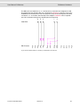
States of the
resistances R_SH
and R_SL
Requirement: CANstressDR with current firmware (as of version 1.23)
The resistances R_SH and R_SL can have the following three states:
Status
Graphic
Series resistance in the CAN line:
R_SH (R_SL) normal in operation
Switched off:
R_SH (R_SL) deactivated and associated
switch closed
Break of the CAN line:
R_SH (R_SL) deactivated and associated
switch open
In order to disconnect the CANH line during an analog disturbance, it is necessary to
click on the RSH resistance until R_SH is deactivated AND the switch below it is
opened.
Limitations
Please be advised that the line disconnection for the individual resistance layouts is
subject to particular limitations:
Layout
Possible line disconnection
Standard
R_SH (CANH), R_SL (CANL)
R_H, R_SH, R_HL (without R_SH)
R_SL (CANL)
R_L, R_SL, R_HL (without R_SL)
R_HL (CANH)
© Vector Informatik GmbH
Version 2.1
- 31 -
CANstress Software
User Manual CANstress
Layout
Possible line disconnection
R_H and R_SL, R_H and R_L, R_SH and R_HL, R_SH and R_SL, R_SH and R_L,
R_HL and R_SL, R_HL and R_H, R_HL
and R_L
Disturbance voltage
By default the supply voltage and disturbance voltage are jumpered together in the
supply connector. However, the disturbance voltage can also be fed in separately.
In the circuit diagram the user can specify whether the resistor should be connected
to the positive (V_D+) or negative (V_D-) pole of the disturbance voltage; this is done
by clicking the switch next to R_H or R_L.
The maximum disturbance voltage that may be used, and which is utilized to check
the configured layout, is displayed next to "Max. disturbance voltage".
Note: The allowable disturbance voltage range given in the technical data must be
observed, since otherwise the equipment could be destroyed!
Maximum
disturbance voltage
This entry only applies to devices of the type CANstressDR; it does not affect devices
of the type CANstressD.
In the file "CANstress.ini" there is the following INI entry:
[Hardware]
ExactDistVoltage=12
ExactDistVoltage gives the maximum disturbance voltage that is fed or may be
fed to the CANstress hardware. The default entry is 12 (Volt).
The value given as ExactDistVoltage is used to calculate loads of resistors R_H,
R_HL and R_L on the Analog Board and to decide wither your selected resistor
values may be transferred to the hardware, or whether they could potentially result in
hardware damage. (See also “Resistor validation “)
If you feed in a different disturbance voltage please observe the following instructions:
¼ The maximum allowable disturbance voltage that may be applied to the hardware
is 40 V.
¼ The disturbance voltage you are applying must be entered in the INI entry
ExactDistVoltage!
Note: You should never specify a disturbance voltage in the INI entry that is lower
than the voltage you actually apply to the device! Otherwise the hardware might
be permanently damaged! Make sure that the INI entry ExactDistVoltage is
always configured correctly.
Resistor layouts:
- 32 -
Besides the Standard layout the following resistor layouts can be defined.
Resistor Layouts
Description
Standard-Layout
When using the Standard layout none of the resistors
may be changed while the hardware is activated.
Therefore, as soon as the hardware is active all user
controls for modifying resistor values (input fields,
rotary fields and sliders) are disabled.
Version 2.1
© Vector Informatik GmbH
User Manual CANstress
CANstress Software
Resistor Layouts
Description
Layout R_H
When using the layout R_H the resistor R_H can be
changed during an active disturbance. This involves
deactivating resistor R_SH, and the hardware connects
it internally to R_H.
Layout R_SH
When using the layout R_SH the resistor R_SH can be
changed during an active disturbance. This involves
deactivating resistor R_H, and the hardware connects
it internally in parallel to R_SH.
Layout R_HL (without
R_SH)
When using the layout R_HL (without R_SH) the
resistor R_HL can be changed during an active
disturbance. This involves deactivating resistor R_SH,
and the hardware connects it internally in parallel.
Layout R_HL (without
R_SL)
When using the layout R_HL (without R_SH) the
resistor R_HL can be changed during an active
disturbance. This involves deactivating resistor R_SH,
and the hardware connects it internally in parallel.
Layout R_SL
When using the layout R_SL the resistor R_SL can be
changed during an active disturbance. This involves
deactivating resistor R_L, and the hardware connects it
internally in parallel to R_SL.
Layout R_L
When using the layout R_L the resistor R_L can be
changed during an active disturbance. This involves
deactivating resistor R_SL, and the hardware connects
it internally in parallel to R_L.
Layout R_H and R_SL
When using the layout R_H and R_SL the resistors
R_H and R_SL can be changed during an active
disturbance. This involves deactivating resistors R_SH
and R_L and connecting them in parallel to R_H and
R_SL.
Layout R_H and R_L
When using the layout R_H and R_L the resistors R_H
and R_L can be changed during an active disturbance.
This involves deactivating resistors R_SH and R_SL
and connecting them in parallel to R_H and R_L.
Layout R_SH and R_HL
When using the layout R_SH and R_HL the resistors
R_SH and R_HL can be changed during an active
disturbance. This involves deactivating resistors R_H
and R_SL, and the hardware connects them internally
in parallel to R_SH and R_HL.
Layout R_SH and R_SL
When using the layout R_SH and R_SL the resistors
R_SH and R_SL can be changed during an active
disturbance. This involves deactivating resistors R_H
and R_L, and the hardware connects them internally in
parallel to R_SH and R_SL.
Layout R_SH and R_L
When using the layout R_SH and R_L the resistors
R_SH and RL can be changed during an active
disturbance. This involves deactivating resistors R_H
and R_SL, and the hardware connects them internally
in parallel to R_SH and R_L.
© Vector Informatik GmbH
Version 2.1
- 33 -
CANstress Software
User Manual CANstress
Resistor Layouts
Description
Layout R_HL and R_SL
When using the layout R_HL and R_SL the resistors
R_HL and R_SL can be changed during an active
disturbance. This involves deactivating resistors R_SH
and R_L, and the hardware connects them internally in
parallel to R_HL and R_SL.
Layout R_HL and R_H
When using the layout R_HL and R_H the resistors
R_HL and R_H can be changed during an active
disturbance. This involves deactivating resistors R_SL
and R_SH, and the hardware connects them internally
in parallel to R_HL and R_H.
Layout R_H and R_L
When using the layout R_H and R_L the resistors R_H
and R_L can be changed during an active disturbance.
This involves deactivating resistors R_SH and R_SL,
and the hardware connects them internally in parallel
to R_H and R_L.
The Standard layout differs from the other resistor layouts in that it is not possible to
adjust resistor values while the hardware is activated.
For all other layouts at least one resistor can be changed even if the disturbance
system is active. Nevertheless at least one other resistor must be deactivated as well.
This requirement is based on the condition that when changing resistor values (during
an active disturbance), the transition to the new resistor value must take place without
any timer periods when a resistor value is undefined. Since one of the resistors is not
used in the resistor layout, internally the hardware can connect this resistor in parallel
to the resistor to be changed. The resistor value is changed while the hardware is
active by alternately having one of the resistors active while the other is passive and
adjusting to the new resistor value. After successfully changing the passive resistor to
the new resistor value, it is activated, and the previously activated resistor is
simultaneously deactivated.
With the exception of the Standard layout, the names of all other layouts indicate
which resistor can be changed while the hardware is activated.
Automatic checking
of resistors
Before the resistor layout is loaded in the hardware, a check is made to determine
whether the configured resistor values could result in hardware damage. This check
involves resistors R_H, R_HL and R_L, in the case where R_H is connected to VD+
and R_L to VD- (or reversed). If the current configuration could result in hardware
damage, this is output in the form of a warning message, and the transfer is prevented. In this case, using commands from the "Edit" menu the user can determine
the next closest resistor value at which this resistor is no longer at risk for damage.
During an active disturbance it is possible that changing the value of one of the
resistors R_H, R_HL or R_L could pose a risk for the hardware. If such a value is set
at the user interface, it is not transferred to the hardware and the resistor identifier in
front of the input field is shown in red (otherwise, if the new value does not pose a
risk, it is shown in black).
To inform the user of the values that are set in the hardware, the individual resistor
values are shown beneath "Resistor values in the hardware" while the hardware is
active. The resistor values shown at these places are the last values reported to the
user interface by the hardware.
Changing the
If a resistor is changed very quickly during an active disturbance (e.g. using a slider)
resistance values
the hardware buffers the requested settings for the resistor and will only switch over
when the hardware is to the most recently requested resistor value approx. every 100 ms.
activated
- 34 -
Version 2.1
© Vector Informatik GmbH
User Manual CANstress
3.3
CANstress Software
CANstress Menus
3.3.1 "File" Menu
Commands:
The "File" menu contains the following commands:
New
Creates a new configuration.
Note: If the active configuration contains unsaved changes, before creating the new
configuration a dialog box appears asking the user whether the changes should be
saved.
Open
Opens the "Open" dialog in which the user can select the configuration to be opened.
The file type 'CANstress (*.cst)' (CANstress configuration) is automatically selected.
After selecting the configuration to be opened and pressing the [Open] button the
configuration is opened and displayed in the CANstress program window.
Note: If the active configuration contains unsaved changes, before opening an-other
configuration a dialog box appears asking the user whether the changes should be
saved.
Save
Saves the active configuration.
Note: If the active configuration was never saved before, a "Save as" dialog appears
in which the memory location and filename can be entered for the configuration. The
file type 'CANstress (*.cst)' (CANstress configuration) is automatically selected.
After selecting the memory location, entering the filename and pressing the [Save]
button the configuration is saved.
Save as
Opens the "Save as" dialog where the user can specify the memory location and
filename under which the active configuration should be saved. The file type
'CANstress (*.cst)' (CANstress configuration) is automatically selected.
After selecting the memory location, entering the filename and pressing the [Save]
button the active configuration is saved under the selected name.
Associate Database
Opens the "Databases" dialog in which one or more CANdb databases can be
associated to the active configuration.
Note: The message information of a CANdb database cannot be used in a
CANstress configuration until the database has been associated to the configuration.
Exit
Closes the active configuration and exits CANstress.
Note: If the active configuration contains unsaved changes, a dialog box appears
asking the user whether the changes should be saved.
Located above the "Exit" command is the list of last opened configurations. The
desired configuration can be opened by clicking its name.
3.3.2 "Edit" Menu
Commands
The "Edit" menu will contain different commands depending on which page of the
dependent on pages: CANstress program window is activated.
© Vector Informatik GmbH
Version 2.1
- 35 -
CANstress Software
"Bit field trigger"
page
User Manual CANstress
¼ "Recessive"
Sets the selected bit or bits to the value '1' (recessive).
¼ "Dominant"
Sets the selected bit or bits to the value '0' (dominant).
¼ "Don't Care"
Sets the selected bit or bits to the value 'x' (don't care).
¼ "Clear"
Deletes the selected bit or bits.
¼ "CRC sequence"
Calculates the CRC sequence for the bit fields beginning with the Start of Frame
up to the last valid data field and inserts the calculated CRC sequence in the
"CRC Sequence" input field.
Note: The "CRC sequence" command is only available if the input fields that are
relevant for the CRC calculation (i.e. all input fields before the "CRC sequence"
input field) do not contain any 'don't care' bits.
"Other trigger" page
¼ "Recessive"
Sets the selected bit or bits to the value '1' (recessive).
¼ "Dominant"
Sets the selected bit or bits to the value '0' (dominant).
¼ "Don't Care"
Sets the selected bit or bits to the value 'x' (don't care).
¼ "Clear"
Deletes the selected bit or bits.
"Disturbance" page
¼ "Recessive"
Sets the selected bit or bits to the value '1' (recessive).
¼ "Dominant"
Sets the selected bit or bits to the value '0' (dominant).
¼ "Analog"
Sets the selected bit(s) or the selected BLT cycle(s) in the "Disturbance
sequence" input box to the value 'a' (analog).
Note: The 'Analog' disturbance state is only available with CANstressDR!
¼ "Undisturbed"
Sets the selected bit(s) or the selected BTL cycle(s) in the "Disturbance
sequence" input box to the value 'u' (undisturbed).
¼ "Clear"
Deletes the selected bit or bits.
- 36 -
Version 2.1
© Vector Informatik GmbH
User Manual CANstress
CANstress Software
"Analog disturbance" ¼ "Valid RH"
page
Finds a resistor value for resistor RH, at which the resistor RH is not at risk for
damage, and inserts the determined value in the "RH" input box.
¼ "Valid RHL"
Finds a resistance value for resistor RHL, at which the resistor RHL is not at risk
for damage, and inserts the determined value in the "RHL" input box.
¼ "Valid RL"
Finds a resistor value for resistor RL, at which the resistor RL is not at risk for
damage, and inserts the determined value in the "RL" input box.
Note: The "Analog disturbance" page is only available with CANstressDR!
The commands of the "Edit" menu can also be accessed from the popup menus of
the bit input fields.
3.3.3 "View" Menu
Commands:
The "View" menu contains the following commands for activating the pages of the
CANstress program window
¼ "Bit field trigger"
¼ "Other trigger"
¼ "Disturbance"
¼ "Analog disturbance" (only available with CANstressDR)
3.3.4 "Disturbance" Menu
Commands:
In the "Disturbance" menu the following commands are available:
Connect
Establishes a connection to the CANstress hardware.
The user can select the port and baud rate for this connection in the "Connection
Parameters" dialog. (Use the "Connect" command ("Options" menu) to open the
"Connection Parameters" dialog.)
If it is not possible to establish a connection, the message "Unable to establish
connection to the disturbance module" appears, which the user must confirm with
[OK].
Note: The status bar shows information on the connection to the CANstress
hardware.
Disconnect
Disconnects the CANstress hardware.
Start
The following actions are executed after choosing the "Start" command:
¼ A check is made to determine whether the active configuration is valid.
¼ A connection is established to the CANstress hardware (unless this has already
been done with the "Connect" command ("Disturbance" menu)).
¼ The active configuration is transferred to the CANstress hardware.
¼ The trigger and disturbance system is activated.
© Vector Informatik GmbH
Version 2.1
- 37 -
CANstress Software
Trigger
User Manual CANstress
If the "Edge" option was selected in the "Software trigger" box of the "Other trigger"
page, this command initiates a single software trigger.
However, if the "Level" option was selected, this command toggles level triggering on
and off.
Note: The "Trigger" command is only available if the software trigger was selected as
a trigger source!
As long as level triggering is activated:
¼ Trigger events continue to be initiated,
¼ A appears in front of the "Trigger" command,
¼ The corresponding Toolbar icon appears as though it were pressed.
Stop
Deactivates the trigger and disturbance system. The CANstress hardware remains
connected.
3.3.5 "Options" Menu
Commanbds:
The "Options" menu contains the following commands:
CAN interface
Opens the "CAN Interface" dialog in which the CAN interface is defined.
CAN parameter
Opens the "Channel Configuration" dialog in which parameters are set for the CAN
interface.
External output
Opens the "External Output" dialog in which the user can select the voltage level that
the external output should assume when the trigger condition is satisfied.
Connect
Opens the "Connection Parameters" dialog in that parameters are defined that are
relevant for connecting the CANstress hardware to the computer.
Other…
Opens the "Further Settings" dialog in which a frequency deviation can be set for
CANstress.
3.3.6 "Help" Menu
Commands:
The "Help" menu contains the following commands:
CANstress Help F1
Calls CANstress help.
About
Opens the "About CANstress" dialog which contains information on the CANstress
software and CANstress hardware.
3.4
CANstress Dialogs
Overview
The following dialogs can be opened by the commands or buttons of the CANstress
software.
3.4.1 "CAN Interface" Dialog
Define CAN interface The CAN interface is defined here.
- 38 -
Version 2.1
© Vector Informatik GmbH
User Manual CANstress
CANstress Software
Open dialog
Use the "CAN Interface" command ("Options" menu) to open this dialog.
Interfaces
The CANstress hardware has the following CAN interfaces:
CAN-Interface 1
Is permanently installed and contains a transceiver for
connecting to a CAN High-Speed Bus
CAN-Interface 2
(Optional) is implemented in the hardware by an interchangeable baby board. The only baby board currently
available has a Low-Speed transceiver.
With an existing connection to the CANstress hardware instead of "CAN Interface 1"
and "CAN Interface 2" the bus type of the interface and its used transceiver is
displayed.
Note: The specific transceiver type installed can be found in the "About CANstress"
dialog after establishing a connection. (Use the "About" command ("Help" menu) to
open the "About CANstress" dialog. With the [More Info] button you can get
information about the CANstress hardware)
3.4.2 "Channel Configuration" Dialog
Configure channels
Parameters for the CAN interface are set here.
Open dialog
Use the "CAN Parameters" command ("Options" menu) to open this dialog.
CAN channel 1
In the "CAN Channel 1" box, which appears on the right side of the dialog
immediately after opening it, the user specifies the CANstress variant, the controller
(SJA1000 from Philips) and the baud rate, and the CANstress hardware is displayed.
Note: The configuration options are the same as the configuration options that are
familiar from CAN controllers, whereby each bit is essentially sampled only once.
The CANstress hardware itself does not contain any controller.
CAN channels
Appearing in the "CAN channels" display box is "CAN 1", which represents the
available CAN channels. Clicking the symbol causes "Setup" to appear beneath the
CAN channel. Clicking or the word "Setup" causes the "CAN Setup 1" box to appear
on the right side, in which the user can configure the baud rate and the Bus Timing
Registers.
Note: The options apply to both CAN channels, i.e. both CAN interfaces.
Baudrate
The user enters the baudrate here.
After entering a different baud rate and pressing the <Tab> or <Enter> key, or clicking
in another input box, the corresponding register values are calculated and entered in
the appropriate input boxes. The "BTR 0 | BTR 1 | Sampling point | BTL cycles | SJW"
table contains the allowable register pairings (see below).
© Vector Informatik GmbH
Version 2.1
- 39 -
CANstress Software
Bus Timing Register
0 or Bus Timing
Register 1
User Manual CANstress
The Bus Timing Registers determine how an individual bit in a serial bit stream is
constructed on the bus, and where it is sampled.
Allowable values for the Bus Timing Registers can be taken from the "BTR 0 | BTR 1 |
Sampling point | BTL cycles | SJW" table (see below) and are selected by clicking in
the table.
Acknowledge On
The option shown in this option box is fixed and cannot be changed.
Clock Frequency
The clock frequency is fixed and cannot be changed.
BTR 0 | BTR 1 |
In this table appears all register pairings BTR 0-BTR 1 permitted for CANstress
Sampling Point | BTL together with the sampling point (in percent of bit duration after the beginning of the
Cycles | SJW
bit), number of BTL cycles and the synchronization jump width (SJW).
A number of different Bit Timing Register pairings exist for any given baud rate, which
determine CANstress behavior with regard to the sampling point, number of BTL
cycles and synchronization jump width (SJW).
Note: A soft synchronization of CANstress occurs exclusively on arriving edges from
recessive to dominant and based on the synchronization jump width (SJW) set in the
"Channel Configuration" dialog.
A hard synchronization occurs on SOF bits (Start Of Frame bits), i.e. on recessive>dominant edges after a minimum of 10 recessive bits.
After clicking a line in the table the values of the Bus Timing Registers are
automatically entered in the appropriate input boxes.
Preview
The option set here does not have any effect whatsoever on the CANstress software
synchronization edge or hardware!
Samples
The number of samples is determined by selection of the Bus Timing Register, and it
cannot be configured, since for CANstress only those combinations of BTR 0 and
BTR 1 are permitted which yield a single sample.
Prescaler
Shown here is the prescaler resulting from the register values.
3.4.3 "External Output" Dialog
Define voltage level
Here the user selects the voltage level to be assumed by the external output when
the trigger condition is satisfied.
Open dialog
Use the "External output" command ("Options" menu) to open this dialog.
3.4.4 "Connection Parameters" Dialog
Define connction
parameters
Here the user defines parameters relevant to connecting the CANstress hardware to
the computer.
Open dialog
Use the "Connect" command ("Options" menu) to open this dialog.
- 40 -
Version 2.1
© Vector Informatik GmbH
User Manual CANstress
CANstress Software
Seriel connection
Under Serial connection the connection parameters for the serial (RS-232-) interface
can be set.
Port
Here the user selects the serial port of the computer to which the CANstress
hardware is connected.
Note: The port cannot be changed if a connection already exists between the
computer and the CANstress hardware.
Baudrate
Here the user sets the baud rate at which communications occur between the
computer and the CANstress hardware.
Note: As long as the connection exists between the computer and the CANstress
hardware, the settings of the interface (port, baudrate,…) can not be changed.
On some computers problems may occur at a baudrate of 115,200 Baud when
establishing a connection. In this case the CAN-stress software automatically sets a
baudrate that is suitable for communications.
The connection via USB has a higher priority than the connection via the serial RS232 interface. Thus a connection to a unit is established as soon as the unit is
connected via USB (even if the unit is also connected via the serial RS-232 interface).
USB interface
For the USB interface no connection parameters must be set. A (CANstress ) unit
connected via USB will be automatically identified and used.
If a connection is done via the USB interface the unit number of the connected
CANstress unit is displayed in the status bar.
3.4.5 "Disturbance Sequence for Bit Field Trigger" Dialog
Generate
disturbances for bit
field trigger
With this wizard (Disturbance Sequence Wizard on page 51) disturbances can
intention-ally be generated within a CAN message. These disturbances are triggered
with bit field triggering.
Additionally, the wizard displays the trigger condition defined on the "Bit field trigger"
page. This portion of the wizard cannot be edited, and it only appears for display
purposes. The end of the non-editable portion is indicated by a '|'. The actual
disturbance can be input after this symbol.
Note: The format of the message for which a disturbance can be specified is the
same as the format of the message specified in the bit field trigger condition.
All input fields up to the CRC sequence must be filled with care bits, e.g. to have the
program offer to calculate the CRC sequence, and so that it can be calculated.
Only care bits may be used in the bit field trigger condition to allow the program to
calculate any occurring stuff bits and to insert them into the disturbance sequence!
The wizard can only be started if there is a non-empty bit field trigger condition (i.e. at
least one bit must be specified in the bit field trigger condition).
The wizard can only be started if the bit field trigger condition is not completely filled
(i.e. at least the input field for End of Frame is not completely filled).
The wizard is only available if the configuration is associated to at least one database.
© Vector Informatik GmbH
Version 2.1
- 41 -
CANstress Software
User Manual CANstress
Example: To disturb the CRC sequence of a specific message, the message is
specified on the "Bit field trigger" page up to the last data field (with care bits!). After
calling the Wizard for creating a disturbance for bit field triggering, the CRC field can
be filled with the calculated CRC sequence. To have this done choose the "CRC
Sequence" command in the CRC field's popup menu. The bit to be disturbed in the
CRC sequence can then be changed.
3.4.6 "Disturbance Message" Dialog
Create disturbance
message
With this wizard (Disturbance Sequence Wizard on page 51) the user can create an
entire disturbance message which, for example, might be initiated by the Start of
Frame trigger. The disturbance message might even be a message conforming to the
CAN specification, and in a strict sense it would then not really represent a
disturbance.
The disturbance message can be specified analogous to the "Bit field trigger" page by
manually filling the individual bit fields. In contrast to the specification of the bit field
trigger condition, don't care bits cannot be used since they do not represent any valid
disturbance status.
As an alternative, the user could select the disturbance message by pressing the
[Message] button in the "Selection of Messages" dialog. Only one message at a time
may be selected here, since a composition of multiple messages is not possible.
The data fields of the selected message are displayed according to the message's
DLC and are filled with recessive disturbance bits. The CRC sequence is calculated
for these data fields accordingly. Therefore, the CRC sequence must be updated after
a change to the data fields.
If an invalid value (e.g. '1111') is specified for the DLC it is not possible to interpret the
data fields in a meaningful way. In this case all data fields are displayed for editing.
In addition to the entries from the edited input fields, when exiting the wizard (with
[OK]) a dominant Start of Frame bit is added at the beginning of the disturbance
message to complete it.
3.4.7 "Disturbance Sequence" Dialog
Create a disturbance Using this dialog, a disturbance sequence consisting of bits/BTLs can be created with
sequence
the same disturbance mode.
Whether the sequence created is a sequence of bits or BTLs depends on the
resolution set for the disturbance result on the Disturbance page.
In this dialog, you can enter:
¼ the Disturbance mode
¼ The disturbance Length with number of bits or BTL cycles
After this, the disturbance duration is displayed automatically.
The calculation occurs with the help of the CAN parameters set in the Channel
configuration dialog box.
The length of the disturbance sequence is (basically) limited to 2048.
¼ The disturbance Duration in µs After this, there is an automatic conversion to the
number of bits or BTL cycles that are required to disturb within this duration.
Possible min. and max. values for the disturbance duration are displayed below
the Duration input field.
- 42 -
Version 2.1
© Vector Informatik GmbH
User Manual CANstress
CANstress Software
Note: The duration can only be set in discrete values (as multiples of the duration of a
bit or a BTL cycle). Authoritative for the duration of the disturbance is the number of
bits (BTL cycles) in connection with the CAN parameters set.
For min. and max. of the disturbance duration for disturbance results based on bits,
the following applies:
¼ Minimum (for length in bits) = 1 / Baudrate (= duration of a bit)
¼ Maximum (for length in bits) = 2048 * 1 / Baudrate (= duration of 2048 bits)
For min. and max. of the disturbance duration for disturbance results based on BTL
cycles, the following applies:
¼ Minimum (for length in BTLs) = 1 / (Baudrate * BTLperBit) (= duration of a BTL
cycle)
¼ Maximum (for length in BTLs) = 2048 * 1 / (Baudrate * BTLperBit) (= duration of
2048 BTL cycles)
BTLperBit is thus the number of BTL cycles per bit, which results from the CAN
parameter settings.
3.4.8 "Error Frame" Dialog
Create a disturbance Using this dialog box, a disturbance sequence, which is equal to an error frame, can
sequence
be created.
The disturbance sequence can be generated from an error flag with n dominant bits
(6 <= n <= 12) and an error delimiter consisting of 8 recessive bits.
If the "Error frame with error delimiter" option is deactivated, the disturbance
sequence is created only from the error flag.
3.4.9 "Databases" Dialog
Assign databases
Here you can associate one or more CANdb databases to the active configuration.
Open dialog
Use the "Associate database" command ("File" menu) to open this dialog.
Assign a database to The message information from a CANdb database cannot be used in a CANstress
a configuration
configuration until the database has been associated to the configuration.
Note: The association of databases performed here only affects the active
configuration. Associations in all other configurations are independent of this action.
Database list
The display box in this dialog contains a list of databases which are associated to the
active configuration. The sequence of databases in the list is utilized to resolve
conflicts when there are ambiguous symbolic names or message identifiers.
"Name" Column
Indicates the name of the database. This name might be used as a name qualifier to
resolve ambiguities.
© Vector Informatik GmbH
Version 2.1
- 43 -
CANstress Software
User Manual CANstress
"CAN" Column
Indicates which CAN chip is assigned to the database. This information is irrelevant
for CANstress, since only one CAN interface is active at any given time.
"Filename" Column
Indicates the database's complete filename and path.
Schaltflächen
The following buttons are available in the dialog.
Button
Function
[Add]
Opens the "Open" dialog in which the user can select the CANdb
database to be associated to the active configuration.
The file type 'CANdb files (*.dbc)' (CANdb database) is
automatically selected.
After selecting the CANdb database and pressing the [Open]
button the selected database is associated.
[Open Editor]
Starts the CANdb Editor and opens the selected CANdb
database.
[Delete]
Removes the selected database from the list, i.e. afterwards this
database is no longer associated to the active configuration.
The database file itself is not deleted by this action.
3.4.10 "Selection of Messages" Dialog
Select messages
Messages can be selected here.
Appearing in the list are the messages of CANdb databases that were associated to
the active configuration. (Use the "Associate database" command ("File" menu) to
associate CANdb databases to the active configuration.)
3.4.11 "Hex/Dec input" Dialog
Value format
This dialog enables you to enter the values on the "Bit field trigger" page in either
hexadecimal or decimal format.
Open and close the
dialog
To open this dialog box, just click the underlined text on the page.
When the dialog is closed, the entered value is converted internally into a binary
number. Finally, as many digits as possible are taken over into the corresponding
input field, beginning with the lowest digit.
Example: The ID in the standard format consists of 11 digits.
If on the "Hex/Dec input" dialog, "0x10" is entered and the dialog is closed with [OK],
the corresponding binary number "10000" is written in the ID input field as
"00000010000". Since not all 11 places of the input field were required for the entered
number, the leading (higher value) places were filled with "0".
If the entered number requires more digits in binary code than can be entered into the
input field, then the "n" lowest value places of the binary number are written in the
input field.
n = number of characters that can be entered into the input field
- 44 -
Version 2.1
© Vector Informatik GmbH
User Manual CANstress
CANstress Software
Note: When switching from decimal to hexadecimal, the entered value is converted
into the other format and displayed. Thus values up to 2147483647 (0x7fffffff) can be
converted correctly. Only then the dialog can be ended with [OK].
3.4.12 "About CANstress" Dialog
Information about
CANstress
The following information about the CANstress software and CANstress hardware is
displayed:
¼ Version number of the CANstress software
¼ Copyright
¼ Hardware information (with the [More Info] button)
(e.g. transceiver type used for CAN Interface 1 or 2, device variant connected
(CANstressDR with analog board to generate analog disturbances or
CANstressD without analog board), and the firmware version used by the
CANstress hardware)
Note: The hardware information is not exchanged between the CANstress hardware
and CANstress software until a connection is established.
If the message "No hardware information available" appears in the "Hardware
Information" display box, then no connection was made between the hardware and
software.
(The connection between hardware and software can be established with the
"Connect" command ("Disturbance" menu).)
Use the "About" command ("Help" menu) to open this dialog.
3.5
Trigger Sources
Initiator of a trigger
event
A trigger source serves as the initiator of a trigger event. The trigger event is initiated
as soon as the trigger condition specified for the trigger source has been satisfied.
The user can select a trigger from the list of available trigger sources for a
disturbance and/or the external output. This selection is made in the "Disturbance"
and "External" list boxes on the toolbar.
Trigger sources
The following trigger sources are available as triggers:
¼ Triggering on CAN bit fields
¼ Triggering on Start of Frame
¼ Triggering on Error Frame
¼ Triggering on End of Frame / Bus Idle
¼ Triggering by external input
¼ Triggering by software (user interface)
¼ Triggering by "Continuous trigger" (for disturbances and external output)
¼ Triggering "Like disturbance" (only for the external output)
© Vector Informatik GmbH
Version 2.1
- 45 -
CANstress Software
User Manual CANstress
A trigger source can be used both to initiate a disturbance and to activate the external
output. It should be noted that a trigger source may only be configured once. For
example, both the disturbance and external output could be triggered by an Error
frame. However, the user may only make an entry one time for the Error frame's error
flag indicating how many dominant bits it must contain to cause triggering.
Basic information on
the trigger
disturbance cycle
Once a trigger condition is satisfied the disturbance is started.
The trigger conditions are evaluated (if the hardware is activated) when a disturbance
has ended or has not been executed yet (i.e. immediately after activation of the
hardware).
A pause after a disturbance cycle also counts as part of the disturbance, i.e. no
trigger conditions are evaluated during this time period.
Time point of
initiation of
disturbance as a
function of the trigger
source
The trigger source used (for the disturbance) also determines the exact time point of
disturbance initiation, i.e. the start of the disturbance action.
With bit field triggering, Error frame triggering and End of Frame/Bus Idle triggering
the disturbance is initiated after the end of the last bit time of the trigger condition.
This means that the disturbance begins with the first BTL clock of the next bit time.
With Start of Frame triggering the disturbance is initiated immediately after detection
of the recessive->dominant edge. The disturbance begins with the first BTL clock
after this edge.
With triggering by the external input and with software triggering the disturbance is
initiated asynchronously. That is, as soon as the trigger condition is satisfied the
disturbance is initiated without waiting for the end of a bit time.
3.5.1 Triggering on CAN Bit Fields (Bit Field Trigger)
Bit feld trigger
The bit field trigger is initiated when the specified bit field trigger condition is satisfied.
The bit field trigger condition defines how the bit fields of a CAN message must be
laid out to satisfy the trigger condition. When specifying the bit field trigger condition
any occurring stuff bits are not considered. For a bit within the trigger condition the
user can specify whether it must be a dominant or recessive bit to cause triggering. If
the user wishes to have triggering occur independent of whether a dominant or
recessive bit occurs at a specific position, a don't care bit can be used for this bit in
the trigger condition.
3.5.2 Triggering on Start of Frame
Start of Frame trigger The Start of Frame trigger is initiated when a recessive-dominant edge is detected
after Bus Idle (10 or more recessive bits). In contrast to the other CAN trigger
sources, triggering here is not initiated after the end of the specific bit, rather it occurs
immediately. In this context immediately means it is ensured that the BTL cycle
occurring immediately after the Start of Frame edge can also be disturbed, although
the disturbance may be somewhat shortened for this cycle.
3.5.3 Triggering on Error Frame
Error Frame trigger
- 46 -
The Error frame trigger is initiated when the Error frame trigger condition is satisfied.
The trigger condition for the Error frame defines how many dominant bits the Error
frame's error flag must contain to cause triggering.
Version 2.1
© Vector Informatik GmbH
User Manual CANstress
3.5.4
CANstress Software
Triggering on End of Frame / Bus Idle
End of Frame / Bus
Idle trigger
The trigger condition for End of Frame triggering specifies how many recessive bits
must follow after a dominant bit to cause triggering. The user can set a value between
8 and 18 for the number of recessive bits. For a system with and least one sender
and receiver this is the number of recessive bits that follow the dominant bit of the
ACK slot (which was sent by the receiver to acknowledge receipt of a message).
For End of Frame / Bus-Idle triggering with 8 recessive bits, for example, triggering
occurs when - after the dominant bit of the ACK slot (of a receiver) - the ACK delimiter
(1 recessive bit) and the subsequent End of Frame (7 recessive bits) have occurred.
Actual End of Frame / Bus-Idle triggering is obtained for a trigger condition with 11
recessive bits: Here triggering occurs when - after the dominant bit of the ACK slot (of
a receiver) - the ACK delimiter (1 recessive bit), End of Frame (7 recessive bits) and
Intermission (3 recessive bits) have occurred.
While it is assured in a network with (at least) two nodes (sender and receiver) that
the bus will be in the Bus Idle state after 11 recessive bits, for a network with only one
node this is only assured after 17 recessive bits (See also "Other Trigger" Page on
page 28, section "End of Frame/Bus-Idle Trigger").
3.5.5 Triggering by External Input
Triggering via
external input
Triggering may also be performed via the external input of the CANstress hardware.
To do this, the state or state change that should be used to cause triggering is
configured over the CANstress user interface.
The following options are available for se-lection:
¼ Low
(Voltage level for Low: See Technical Data of the CANstress Hardware)
¼ High
(Voltage level for High: See Technical Data of the CANstress Hardware)
¼ Low->High (Triggering on transition from Low to High)
¼ High->Low (Triggering on transition from High to Low)
Note: If the external input on the toolbar is selected as a trigger source, the external
input is used automatically as an external trigger on the Other Trigger page. Thus the
external input can not longer be used as a trigger enable signal.
If the external input is not used for triggering, it can be used as a trigger enable
signal. The trigger enable signal is a supplemental condition for triggering. Only if the
actual trigger condition AND the trigger enable signal occur simultaneously does
triggering occur. A low (LOW) or high (HIGH) level may be selected for the trigger
enable signal.
3.5.6 Triggering by Software
Software trigger
The software trigger can be initiated from the user interface. The user configures
whether the trigger condition is satisfied for only a brief time (Edge triggering) by
choosing the "Trigger" command, or whether the trigger condition remains satisfied
until the command is chosen again (Level triggering).
© Vector Informatik GmbH
Version 2.1
- 47 -
CANstress Software
User Manual CANstress
3.5.7 Triggering by "Continuous trigger"
Continuous trigger
The "Continuous trigger" is triggered immediately after disturbance start
(Disturbance|Start).
With the "Limited duration" option, the continuous trigger will only be switched off
when the disturbance ends (Disturbance|Stop).
With the "Duration" option, you can set the time after which the continuous trigger will
be ended automatically. The time-controlled continuous trigger can only be ended
prematurely by selecting Disturbance|Stop.
Note: The trigger sources "Continuous trigger" and "Software" cannot be used
simultaneously since the continuous trigger is already implemented in the program as
a software trigger.
For the "Continuous trigger", the "as trigger enable" setting of the external input will
not be considered or used.
Purpose
The "Continuous trigger" can be used immediately after Disturbance|Start to disturb
the bus continuously, for example with an analog disturbance, or to cause error
frames.
With the "Duration option", a time can be specified which, in connection with the
"Continuous disturbance (while trigger)" disturbance mode, creates a disturbance for
precisely the specified duration.
3.5.8 Triggering "Like disturbance"
Trigger external
output with each
disturbance
The trigger source "Like disturbance" can only be used for the external output.
With use of this trigger, the external output is triggered with each triggering of a
disturbance. If all disturbances or disturbance cycles have been executed, it will no
longer be triggered.
Example:
¼ If you want to disturb the message with the ID 0x100 precisely once on its first
occurrence, then enter the ID 0x100 as trigger condition for the bit field triggering
and enter "Limited number of disturbances" in the disturbance mode. For the
number of disturbance cycles and for the number of disturbances (per cycle),
select 1.
¼ If you want to watch precisely this one case with the oscilloscope, then trigger the
oscilloscope via the external output and select "Like disturbance" as the trigger
source.
¼ If, by contrast, you want to trigger the external output (or the oscilloscope) on
each occurrence of the ID 0x100, then you must select the "Bit field trigger" for
the external output since with this trigger condition triggering will still occur even
when there is no more disturbance.
Note: The use of the trigger source "Like disturbance" requires a CANstress firmware
Version 1.23 or higher.
- 48 -
Version 2.1
© Vector Informatik GmbH
User Manual CANstress
3.6
CANstress Software
Disturbances (Disturbance Actions)
Influence of the bus
When the user exercises a defined type of influence on the CAN bus by means of the
CANstress hardware this is referred to as a Disturbance. A user-defined (disturbance)
pause after a disturbance sequence is therefore just as much a part of a disturbance
as the disturbance sequence itself.
The following disturbance states can be generated on the bus with CANstress:
¼ dominant
¼ recessive
¼ analog (only in the CANstressDR version)
¼ undisturbed
Disturbance
sequence
The disturbance states may be combined on both the BTL and Bit levels to create a
disturbance sequence. The length of the disturbance sequence is limited to 2048 bits
or BTL cycles. Only one disturbance state may be used within one bit time (for
definition of the disturbance sequence on the bit level) or within one BTL clock time
(for definition of the disturbance sequence on the BTL level).
'dominant'
disturbance state
With the 'dominant' disturbance state a state is produced on the bus which
corresponds to a dominant bit according to the hardware interface used (Low-Speed
or High-Speed).
'recessive'
disturbance state
Similarly, with the 'recessive' disturbance state a state is produced on the bus which
corresponds to a recessive bit according to the hardware interface used (Low-Speed
or High-Speed). That is, a dominant bit sent by a network node can be 'over-written'
by a recessive disturbance bit.
'analog' disturbance
state
With the 'analog' disturbance state a state is produced on the bus which can be
parameterized by a resistor matrix and a capacitor matrix and an external disturbance
voltage. This state can be used to simulate external disturbances (e.g. line losses).
'undisturbed'
disturbance state
The 'undisturbed' disturbance state is actually not a disturbance state at all, since it
leaves the existing bus state unaffected. However, in some applications it may be
needed within a disturbance sequence to leave individual bits undisturbed on the
CAN bus.
3.6.1 Time Point of Disturbance
Trigge the
disturbance
The exact time point at which a disturbance is initiated or the disturbance action is
started (e.g. synchronous to the beginning of a BTL clock cycle or asynchronously)
depends on the trigger source used.
3.6.2 External Disturbance Voltage
External disturbance
voltage
By default the supply voltage and disturbance voltage are jumpered together in the
supply connector. Nevertheless, the disturbance voltage may also be fed in
separately.
Cross reference: For the allowable disturbance voltage range: See Technical Data
of the CANstress Hardware.
© Vector Informatik GmbH
Version 2.1
- 49 -
CANstress Software
3.7
User Manual CANstress
Disturbance Mode
3.7.1 'Unlimited Number of Disturbances' Disturbance Mode
Disturbance
sequence after each
trigger
In the 'Unlimited number of disturbances' disturbance mode the defined disturbance
sequence is initiated after each (disturbance) trigger. The number of disturbances to
be performed is unlimited here.
The disturbance sequence used as a disturbance may be defined on both the bit level
and the BTL level.
3.7.2 'Limited Number of Disturbances' Disturbance Mode
Disturbance within
defined disturbance
cycles
In the 'Limited number of disturbances' disturbance mode a disturbance is repeated
for m disturbance cycles (m=1 to 65535, or infinite). For one disturbance cycle the
user can configure the number of disturbances n (n=1 to 255) which indicates how
many disturbance sequences are initiated per disturbance cycle. A trigger is needed
to initiate each disturbance sequence.
Besides specifying the number of disturbances per disturbance cycle, in this
disturbance mode the user can also configure the length of the pause p (p=1 to 65535
ms) that should occur after a disturbance cycle has been run (i.e. after n
disturbances) and before the trigger condition for the disturbance sequence is
evaluated again.
The number of disturbance cycles may be unlimited. However, the number of
disturbances in one disturbance cycle is limited to 255.
The pause time is of interest, for example, in applications in which after multiple
disturbances a disturbance pause is inserted to allow the network to recover from any
error states that may have occurred.
3.7.3 'Continuous Disturbance (while trigger)' Disturbance Mode
Time limited
disturbance
In the 'Continuous disturbance (while trigger)' disturbance mode the bus can be
disturbed continuously with a selectable disturbance type (dominant, recessive or
analog). The disturbance is applied as long as the trigger condition is satisfied. For
ex-ample, if the continuous disturbance is initiated by a software trigger with the Edge
triggering option, then the disturbance is only performed briefly. On the other hand, if
the continuous disturbance is initiated by a software trigger with the Level triggering
option, a disturbance is produced until the software trigger is deactivated.
Note: For configurations that can lead to a brief continuous disturbance, a warning
message is displayed.
3.7.4 'Continuous disturbance (until stop)' disturbance Mode
Continuous
disturbance
- 50 -
The 'Continuous disturbance (until stop)' disturbance mode is an expansion of the
'Continuous disturbance' disturbance mode. Here the bus with a configurable
disturbance mode (dominant, recessive or analog) can be disturbed continuously too.
The disturbance begins with Disturbance|Start and continues until
Disturbance|Stop.
Version 2.1
© Vector Informatik GmbH
User Manual CANstress
CANstress Software
3.7.5 'Continuous disturbance (time limited)' disturbance Mode
Continuous
disturbance
3.8
The 'Continuous disturbance (time-limited)' disturbance mode is an expansion of the
'Continuous disturbance' disturbance mode. In addition to a disturbance mode
(dominant, recessive or analog), a duration for the disturbance can be selected. Upon
occurrence of a trigger event, the continuous disturbance will be placed on the bus for
the specified duration. After the time has elapsed (that is, after the disturbance has
been executed), the hardware switches to the "READY" state.
Disturbance Sequence Wizard
Cteate disturbance
sequences
The following disturbance sequence wizards provide support in creating disturbance
sequences:
¼ Disturbance Sequence Wizard for Bit Field Triggering
("Disturbance Sequence for Bit Field Trigger" Dialog on page 41)
¼ Disturbance Sequence Wizard for Disturbance Message
("Disturbance Message" Dialog on page 42)
¼ Disturbance Sequence Wizard for disturbance sequence
("Disturbance Sequence" Dialog on page 42)
¼ Disturbance Sequence Wizard for error frame
("Error Frame" Dialog on page 43)
Note: (valid for "Disturbance Sequence Wizard for bit field triggering" and
"Disturbance Sequence Wizard for disturbance message"):
Only the dominant and recessive disturbance states may be used within the wizards.
After exiting the wizards with [OK] the entries are copied over to the "Disturbance
sequence" input box. Since the entries within the wizards do not contain any stuff bits,
while the actual disturbance sequence does contain stuff bits, the entries made within
the wizards are provided with stuff bits accordingly. In doing so, consideration is given
to stuffing bits only in the range between the Start of Frame and the CRC Sequence
(including both of these).
If BTL cycles was selected as the resolution on the "Disturbance" page before calling
the wizard, when the wizard is exited the bit disturbance sequence that was created is
converted to BTL cycles. This is based on the BTL cycles per bit value configured in
the "Channel Configuration" dialog.
Within the Disturbance Sequence Wizard empty input fields lying between the Start of
Frame and the input field with the last entry are filled up with recessive disturbance
bits.
3.9
Configuration
Process of trigger
and disturbance
The triggering and disturbance processes are controlled by the user-defined
configuration.
© Vector Informatik GmbH
Version 2.1
- 51 -
CANstress Software
User Manual CANstress
The configuration is determined by various parameters:
¼ Configuration of the trigger source for the disturbance
Configuration of the trigger source defines the circumstances under which the
disturbance trigger should be initiated.
¼ Configuration of the disturbance mode
Configuration of the disturbance mode defines the type (e.g. continuous
disturbance) and duration (e.g. once or infinite) of the disturbance.
¼ CAN Parameters
The parameters 'Bus Timing Register 0' and 'Bus Timing Register 1' are used to
define the baud rate, the number of BTL cycles per bit, and the sampling point
within a bit. (Use the "CAN Parameters" command ("Options" menu) to open the
"Channel Configuration" dialog, in which these parameters can be defined.)
¼ CAN Interface
The CAN Interface option specifies which hardware interface is used to establish
a connection with the CAN bus. (Use the "CAN Interface" command ("Options"
menu) to open the "CAN Interface" dialog in which these options can be defined).
¼ CAN Database
The same database used as the basis for selecting messages is also needed to
display symbolic message names (e.g. the name of the message on whose
identifier bit field triggering should trigger).
A CANstress configuration is saved in a file with the filename extension CST.
3.10 Establishing a Connection
3.10.1 Via USB port
USB port
If a CANstress hardware is connected to the PC via USB the connection is
established via USB. This connection has a higher priority than the connection via the
serial RS-232 port. For the USB port no connection parameters must be set.
3.10.2 Via serial RS-232 port
RS-232 port
For the most part the CANstress software handles the connection process
autonomously. The only parameters needed are the serial port to be used and the
baud rate, which are input in the "Connection Parameters" dialog (Use the "Connect"
command ("Options" menu) to open the "Connection Parameters" dialog).
The status of the momentary connection state can be seen on the status bar.
If problems occur while establishing a connection between the CANstress software
and the hardware, you should check the following:
¼ Is the CANstress hardware operationally ready?
¼ Is a serial cable being used for the connection between the computer and the
CANstress hardware? A so-called NULL modem cable is unsuitable for this
purpose.
¼ Is the serial port already being used by another application? In this case the other
application must be closed.
- 52 -
Version 2.1
© Vector Informatik GmbH
User Manual CANstress
CANstress Software
Note: For applications in a MS-DOS shell it is often insufficient to just exit the
application. Usually the serial port is not made available until the MS-DOS shell is
closed.
¼ Is the port selected in the "Connection Parameters" dialog available in the
system?
Some interface cards (e.g. graphic cards) with a PS2 mouse reserve the interrupt
sources used for the serial ports by default. If the computer has such a card, the
interrupt allocations should be checked under the system settings on the control
panel.
3.11 Working with CAN Databases
Create, edit and
assign databases
CANstress supports working with CAN databases. CAN databases contain
assignments between message identifiers and symbolic message names as well as
signals which symbolically describe data segments within messages. CAN databases
can be created and edited in the form of CANdb databases with the help of the
CANdb Editor.
The CANdb database must be associated to the CANstress configuration to make it
possible to use the information from the CAN database within CANstress. (Use the
"Associate database" command ("File" menu) to associate one or more databases to
the active CANstress configuration.)
The messages contained in the associated CANdb databases can be used to
formulate both a bit field trigger condition and a disturbance message.
Note: If a DBC database is associated to a configuration, the message name is
displayed whenever possible after "Symb. ID:" located beneath the "Arbitration Field"
input box on the "Bit field trigger" page.
© Vector Informatik GmbH
Version 2.1
- 53 -
User Manual CANstress
CANstress Hardware
4 CANstress Hardware
In this chapter you find the following information:
4.1
Block Circuit Diagram
page 56
4.2
Connections
Voltage Supply
USB Port
RS 232 Port
CAN Interface
Trigger Input
Trigger Output
page 56
4.3
LED Indicators
page 66
4.4
Hardware States
page 67
4.5
Technical Data
General Technical Data
Voltage Supply
CAN Interface
CAN Disturbance Section
RS 232 Interface
Trigger Input
Trigger Output
page 68
© Vector Informatik GmbH
Version 2.1
- 55 -
CANstress Hardware
4.1
User Manual CANstress
Block Circuit Diagram
Construction
CANstress hardware
The block circuit diagram (compare Figure 4) clarifies the basic construction of the
CANstress hardware as well as the following actions taken to achieve electrical
isolation of the various system components:
¼ The negative pole of the supply voltage (GND) represents the reference voltage
for the CAN interface (CANGND).
¼ The fed-in disturbance voltage has its own reference voltage which need not be
identical to GND.
¼ The RS 232 port is electrically isolated from all other components.
¼ The USB interface is electrically isolated from all other components.
¼ Trigger input and trigger output utilize a common reference voltage, but they are
electrically isolated from all other components.
¼ There are no connections whatsoever to the metal housing internal to the device.
Disturb. Voltage
Supply
Triger Out
Triger In
CAN 1
64 KB ROM
Boot Code
Disturbance
Generation
Analog
Supply
RS-232
+5 V
0V
Supply
Trig.I/O
+5 V
0V
Main
Supply
+5 V
+12 V
+45 V
-10 V
Supply
USB
+5 V
+3,3 V
0V
CAN 2
Isolation
CAN Transceiver
High-/Low-Speed
TrigCAN
Isolation
RS-232 Driver
Galvanical
Galvanical
Disturbance
Generation
Digital
512 KB Flash
Firmware
8-40 V
TTL Driver
CAN Trigger
Control
Kernel
USB Driver
RS-232 Control
USB Control
Trigger Evaluation
Disturbance Generator
Isolation
32 KB RAM
(high speed)
512 KB RAM
Galvanical
Metal Housing
Disturbance
Generator
Supplies
+10 V
13 chan.
Block circuit diagram of the CANstress hardware
4.2
Connections
Connections
- 56 -
The electrical connections of the CANstress hardware are fed out via jacks and
connectors on the upper front side of the device. All connections can be secured by
screws, screw closures or bayonet nut connectors (BNC).
Version 2.1
© Vector Informatik GmbH
User Manual CANstress
CANstress Hardware
4.2.1 Voltage Supply
Voltage supply
4.2.1.1
Construction
The supply voltage may lie at any desired voltage between 8 and 40 V DC.
Independent of the applied voltage, the maximum power consumption is 8 Watt for
the CANstressD and 20 Watt for the CANstressDR. This yields a maximum current
consumption of 670 mA (CANstressD) and 1700 mA (CANstressDR) at 12 V or 340
mA and 850 mA respectively at 24 V. The supply input is protected against re-verse
polarity and is protected against excessive current consumption by an internal
selfresetting circuit breaker.
Voltage Supply Connector
The voltage supply connector of the CANstress hardware has five pins (Binder Series
711).
Supply Connector (view of the connector contacts on the device)
PIN out
4.2.1.2
Construction
Pin out of voltage supply connector:
PIN
Function
1
Positive pole of supply
2
Disturbance voltage +
3
Negative pole of supply
4
Disturbance voltage -
5
Housing ground
Voltage Supply Cable
In the supply cable provided (see figure, opposite) the connections for supply and
disturbance voltages are jumpered together so that the same voltage is used for both
purposes.
© Vector Informatik GmbH
Version 2.1
- 57 -
CANstress Hardware
User Manual CANstress
-
+
711/5 female
1
2
3
4
5
711/5 male
+
-
Supply
+
-
Disturbance Voltage
Housing
Supply cable
If a disturbance voltage is applied which deviates from the supply volt-age, these
jumpers should be re-moved at the connector, and one or two additional lines should
be attached for the feed.
Using Pin 5 of the supply connector it is possible to set the housing ground to a
defined voltage level. When utilized in a motor vehicle, a direct connection to the
negative supply voltage (vehicle ground) presents itself as an option. If relevant to the
particular application, it may be advisable to make a connection to the ground
conductor of the installation. If Pin 5 is left un-connected (this is the case on the
voltage cable provided), no voltage level is applied to the housing.
Maximum
disturbance voltage
This entry only applies to devices of the type CANstressDR; it does not affect devices
of the type CANstressD.
In the file "CANstress.ini" there is the following Ini entry:
[Hardware]
ExactDistVoltage=12
ExactDistVoltage gives the maximum disturbance voltage that is fed or may be
fed to the CANstress hardware. The default entry is 12 (Volt).
The value given as ExactDistVoltage is used to calculate loads of resistors R_H,
R_HL and R_L on the Analog Board and to decide wither your selected resistor
values may be transferred to the hardware, or whether they could potentially result in
hardware damage. (See also “Resistor validation “)
- 58 -
Version 2.1
© Vector Informatik GmbH
User Manual CANstress
CANstress Hardware
If you feed in a different disturbance voltage please observe the following instructions:
¼ The maximum allowable disturbance voltage that may be applied to the hardware
is 40 V.
¼ The disturbance voltage you are applying must be entered in the INI entry
ExactDistVoltage!
Note: You should never specify a disturbance voltage in the INI entry that is
lower than the voltage you actually apply to the device! Otherwise the hardware
might be permanently damaged! Make sure that the INI entry ExactDistVoltage is
always configured correctly.
4.2.2 USB Port
Construction
The alternative USB port is fed out via a four-pin connector (Binder Series 711) and
conforms to the USB High-Speed Standard (12 MBit/s).
USB connector (View of the connector contacts on the device)
PIN our
Pin out of the connector for the USB port:
PIN
Function
1
USB Supply
2
Data line D+
3
Data line D-
4
USB Ground
The USB port is also electrically isolated; therefore the pins do not have any electrical
connection to other components.
In USB terminology CANstress is 'self-powered'. Therefore no operating current is
taken from the USB supply line. These pins only serve to detect whether or not a USB
hub is connected.
4.2.3 RS 232 Port
Construction
The port conforms to the RS 232 standard and permits connection to one of the COM
ports of a PC via a serial 1:1 adapter cable (DB-9 connector to DB-9 socket).
© Vector Informatik GmbH
Version 2.1
- 59 -
CANstress Hardware
User Manual CANstress
RS 232 connector
PIN out
Pin out of the connector for the RS 232 control interface:
PIN
Function
2
RS-232 data output
3
RS-232 data input
5
RS-232 ground
Pins not listed here are not used. Therefore, it is sufficient to connect only pins 2, 3
and 5 to the PC via a three-conductor cable. Please note that due to the internal
electrical isolation, Pin 5 ('RS 232 Ground') also has no conductive path to the supply
reference voltage.
4.2.4 CAN Interface
Interface lines
The block circuit diagrams of the CAN interfaces (compare Figure 9) and digital or
analog disturbance units (compare Figure 10) clarify the terminal assignments and
uses of the externally accessible interface lines.
¼ The CAN signals for generating trigger events are evaluated via the TrigCANH
and TrigCANL connections. The digital disturbance types 'recessive' and
'dominant' are also output over these two connections. In the standard cable
TrigCANH is jumpered to CAN1H and TrigCANL to CAN1L.
¼ CAN_GND represents the reference voltage of the bus signals. If the High-Speed
interface is being used, connection of CAN_GND is optional. When using the
Low-Speed interface connection of CAN_GND is mandatory.
¼ The supply voltage for the Low-Speed transceiver is fed in via Ubatt – which acts
as the operating voltage for the rest of the transceivers used in the CAN system.
Alternatively, Ubatt may be left unconnected, and in this case an internal power
supply generates a regulated voltage of +12V for the transceiver supply. Ubatt is
not necessary for operation of the High-Speed interface.
¼ RTH and RTL supply the voltages needed for a Low-Speed bus termination by
1 kΩ internal resistors. If required these connections can be made to the bus lines
directly or via supplemental external resistors in the cable connector.
¼ With CANstressDR, CAN1H and CAN1L represent the inputs and CAN2H and
CAN2L the outputs of the analog disturbance unit, consisting of 5 resistor
matrices and a capacitor matrix. In the standard cable CAN1H is jumpered to
TrigCANH and CAN1L to TrigCANL.
¼ With CANstressD (no analog disturbances) the input CAN1 is connected through
directly to the output CAN2.
¼ The total of 8 fusible links (2 A) protect the switching FETs from being destroyed
in the event of a short circuit (it does not, however, prevent a possible overload of
the resistors). If the 50 mΩ additional line resistance resulting from each fuse link
is not desired each fuse can be jumpered to adjacent solder pads by means of a
soldering jumper.
- 60 -
Version 2.1
© Vector Informatik GmbH
CANstress Hardware
Disturbance
dominant
Disturbance
rezessive
Trigger
TrigCANH
High-Speed CAN
User Manual CANstress
TrigCANL
CAN_GND
Ubatt
Disturbance
rezessive
RTH
Disturbance
dominant
RTL
Low-Speed CAN
Trigger
Block circuit diagram of the CAN interface
Udist+
CANstress DR
RH
RSH
CAN1H
CAN2H
CHL
RHL
CAN1L
CAN2L
RSL
RL
Udist-
CANstress D
CAN1H
CAN2H
CAN1L
CAN2L
Block circuit diagram of the digital or analog disturbance section
© Vector Informatik GmbH
Version 2.1
- 61 -
CANstress Hardware
4.2.4.1
Construction
User Manual CANstress
CAN Interface Connector
The CAN connector of the CANstress hardware has 15 pins.
CAN connector
PIN out
4.2.4.2
Pin out of the connector for the CAN:
PIN
Function
1
CAN_GND
2
CAN1L
3
CAN2L
4
CAN_GND
5
CAN1H
6
CAN2H
7
Unused
8
Ubatt
9
RTL
10
TrigCANL
11
CAN_GND
12
RTH
13
TrigCANH
14
CAN_GND
15
Ubatt
CAN Connection Cable
Construction
A 60 cm long adapter cable is included with the product for connecting the CANstress
hardware to a bus system. It converts the 15-pin connector of the CAN connection to
two DB-9 connectors (one connector and one socket each).
PIN out
The pin outs of the two DB-9 connectors conform to CIA recommendations.
- 62 -
PIN
Function
2
CAN_L
3
CAN_GND
6
CAN_GND
7
CAN_H
9
Ubatt
Version 2.1
© Vector Informatik GmbH
User Manual CANstress
CANstress Hardware
The DB-9 pins not listed here (1, 4, 5 and 8) are by convention not assigned to CAN
bus signals and are therefore also not connected to CANstress. However, since many
installations use these pins for their own purposes, they are fed through the two DB-9
connectors 1:1. As a result, with the help of the adapter CANstress can be "spliced"
into CIA-conformant wiring at any desired point of the bus line.
9
6
3
8
11
1
7
2
13
10
CAN: DB-9
DB-15 female
5
2
12
9
4
14
15
3
6
Layout of the simplified cable for connecting a CANstressD to the CAN bus
© Vector Informatik GmbH
Version 2.1
- 63 -
CANstress Hardware
User Manual CANstress
CAN1: DB-9 female
1
4
5
8
3
6
9
2
7
CAN2: DB-9 male
res
res
res
res
res
res
res
res
CAN1Gnd3
CAN2Gnd3
CAN1Gnd6
CAN2Gnd6
Ubatt1
Ubatt2
CAN1L
CAN2L
CAN1H
CAN2H
1
4
5
8
3
6
9
2
7
DB-15 female
5
2
8
11
1
12
9
13
10
4
14
15
3
6
DB-15 male
H L
CAN1
H L
TrigCAN
L H
CAN2
RTH RTL
CANstress internal
Ubatt
Connection provided in the standard cable
May break connection corr. to user-specific cable configuration
Additional connection corr. to user-specific cable configuration
Layout of the standard cable for connecting the CANstress hardware to the CAN bus
- 64 -
Version 2.1
© Vector Informatik GmbH
User Manual CANstress
CANstress Hardware
6
3
11
1
7
2
13
10
CAN: DB-9
DB-15 female
5
2
8
12
9
4
14
15
3
6
Layout of the simplified cable for connecting a CANstressDR to a High-Speed bus.
4.2.4.3
Construction
CAN Low-Speed Adapter
According to most low-speed CANtransceivers' (e.g. TJA1054) datasheets, a bus
connection of 500 Ohm to 16 kOhm is required.
For low-speed CAN, the recessive level can be created with 2 terminating resistors
RTH and RTL. These resistors exist on each node.
Thus the resulting terminating resistance is equal to the parallel connection of all
these resistances.
The transceiver datasheet now prescribes a max. and min. resistance
RTH/L(max,min): RTH/L(max) = 16kOhm; RTH/L(min)=500 Ohm.
CANstress has incorporated 2 resistors with 1kOhm, which are normally not activated
since they can have a disturbing effect on high-speed CAN.
If CANstress (without low-speed adapter) is connected to a CANbus that has an
extremely high terminating resistor, e.g. only 1 single CANcab (4.7 KOhm), then it is
possible that due to the high total resistance within the permissible time (depending
on baudrate, bus capacity), no sensible recessive level is created and the
transmission will fail.
In this case, the total resistance must be lowered, which can be achieved with the
activation of the CANstress low-speed adapter.
If, by contrast, CANstress is connected to a bus that is already correctly terminated,
then the internal resistances are not required. In most cases, they have no disturbing
effects.
If, nevertheless, the low-speed adapter is used, the total resistance reduces itself
accordingly. If may not fall below the 500 Ohm mentioned above.
© Vector Informatik GmbH
Version 2.1
- 65 -
CANstress Hardware
Conclusion
User Manual CANstress
In general, when using CANstress on a low-speed bus, the use of the low-speed
adapter is recommended.
In special cases in which the additionally-connected CANstress on the bus should
attract as little attention as possible, however, the LS adapter should not be used.
4.2.5 Trigger Input
Functions
The trigger input is designed as a BNC socket and can assume the following
functions by configuration at the user interface:
¼ Switched off:
The input is non functional.
¼ External trigger:
A trigger signal is fed in - the user can select triggering on a falling edge, rising
edge, HIGH level or LOW level. This signal is OR'd with any other enabled trigger
sources.
¼ Trigger enable:
Functionality of the remaining activated trigger sources is enabled/disabled by
HIGH or LOW level.
The trigger input is laid out as a TTL input and is provided with a pull-up resistor
which fixes the level to HIGH when the input is open. The BNC housing is at logical
LOW (0 Volt) so that it is also possible to connect a passive switch. Closure of this
switch then generates a falling edge.
A self-resetting circuit breaker (100 mA) prevents damage to the input if voltages are
applied which lie outside of the allowable TTL range.
4.2.6 Trigger Output
Control other
evaluation systems
The trigger output is similarly designed as a BNC socket and serves to control other
evaluation systems with CANstress trigger information.
The reaction of the trigger output can be programmed independent of disturbance
generation. The active level is logical HIGH.
Here too the BNC housing is at logical LOW (0 Volt) and is conductively connected to
the BNC housing of the trigger input. There are no electrical connections to other
components.
4.3
LED Indicators
Status information
In normal operation the LEDs of the CANstress hardware indicate the following status
information:
LEDs of the CANstress hardware
- 66 -
Version 2.1
© Vector Informatik GmbH
User Manual CANstress
Device errors
CANstress Hardware
LED
Status information
Run
Operational indicator (flashes continuously)
Trigger Enable
If this LED illuminates, triggering of the disturbance system
is enabled (externally).
If it was configured at the user interface that the trigger
input should not be used as an enable signal, this LED
illuminates continuously.
Trigger Active
If this LED illuminates the next trigger will initiate a
disturbance.
Disturbance Active
If this LED illuminates a disturbance is currently being
generated.
Immediately after activation any device errors are indicated as follows:
¼ All LEDs continuously off:
No supply. Either no supply voltage is being provided or the power plug is
defective.
¼ All LEDs illuminate continuously:
Supply exists but device is defective.
¼ LED 'Disturbance Active' flashes, all other LEDs off:
Device self-test detected a fault.
Other indicator options outside of normal operation:
¼ All LEDs flash together at 5 Hz:
The Bootstrap Mode is active. If this occurs autonomously after power-up, then
there is no valid operating software ('Firmware') in the Flash-ROM. The operating
software must be installed.
4.4
Hardware States
States:
The CANstress hardware can assume the following states:
IDLE
In the IDLE state the hardware is deactivated for triggering and disturbing. This state
is reached when the user ends an active disturbance with the "Stop" command
("Disturbance" menu).
ARMED
In the ARMED state the hardware is activated for triggering and disturbing. This state
is reached when the user starts a disturbance with the "Start" command
("Disturbance" menu).
READY
The READY state is reached when the configured number of disturbances has been
performed. The hardware is therefore deactivated for disturbing. The hardware for
triggering continues to be activated.
© Vector Informatik GmbH
Version 2.1
- 67 -
CANstress Hardware
4.5
User Manual CANstress
Technical Data
4.5.1 General Technical Data
Parameter
Conditions
Min.
Typ
Max.
Units
Ambient temperature
(Operation)
-10
70
°C
Ambient temperature
(Storage)
-40
85
°C
Total weight
Dimension
(length x width x depth)
CANstressD
770
g
CANstressDR
990
g
Aluminum case
151x168x53
mm
Total
163x172x57
mm
4.5.2 Voltage Supply
Parameter
Conditions
Supply voltage
Min.
Typ
8
Power consumption
Current draw at
Uin = 12 V
Max.
Units
40
V
CANstressD
4,5
8
W
CANstressDR
10
20
W
CANstressD
375
670
mA
CANstressDR
850
1700
mA
Fuse protection
(self resetting)
4
A
Disturbance voltage
between Udist+, Udist-
CANstressDR
-48
+48
V
Udist+ to Ground of the
supply
CANstressDR
-8
+40
V
Udist- to Ground of the
supply
CANstressDR
-8
+40
V
Max.
Units
4.5.3 CAN Interface
4.5.3.1
Operation of the CAN High-Speed Interface
Parameter
- 68 -
Conditions
Min.
Typ
CAN data rate
5
1000
KBit/s
Voltage at TrigCANH, TrigCANL, CAN1H, CAN1L,
CAN2H, CAN2L to
CAN_GND
-8
+40
V
Ditto, disturbance function
not assured
-40
+40
V
Diff. input resistance
20
100
kΩ
Version 2.1
© Vector Informatik GmbH
User Manual CANstress
4.5.3.2
CANstress Hardware
Operation of the CAN Low-Speed Interface
Parameter
Conditions
CAN data rate
Min.
Typ
Max.
Units
5
125
KBit/s
Voltage at TrigCANH, TrigCANL, CAN1H, CAN1L,
CAN2H, CAN2L to
CAN_GND
Specified
functionality
-8
+27
V
Voltage at TrigCANH, TrigCANL, disturbance function
not assured
Unlimited
-10
+27
V
Dito
t<0,1 ms,
Ubatt>0
-40
+40
V
Voltage at CAN1H, CAN1L,
CAN2H, disturbance
function not assured
Unlimited
-40
+40
V
Internal resistances at RTH,
RTL
950
1000
1050
Ω
Min.
Typ
Max.
Units
4.5.4 CAN Disturbance Section
Parameter
Conditions
Output current CANH/CANL
'dominant' digital
disturbance (CAN
transceiver)
CAN High-Speed
200
mA
CAN Low-Speed
100
mA
CAN High-Speed
2000
mA
Output current CANH/CANL
'recessive' digital
disturbance
CAN Low-Speed
Adjustment range:
Resistor matrix
mA
0
Step-width:
Resistor matrix
10237 Ω
2,5
Accuracy
(referenced to adjusted
value)
0,1
Adjustment range:
Capacitor matrix
0
Step-width:
Capacitor matrix
Ω
%
15750 pF
250
Accuracy:
(referenced to adjusted
value)
pF
1
%
Continuous current:
FET switch
Unlimited
2
A
Continuous current: Relay
Unswitched
1,2
A
0,5
A
Switching current: Relay
© Vector Informatik GmbH
Version 2.1
- 69 -
CANstress Hardware
User Manual CANstress
Parameter
Conditions
Pulsed current: FET switch,
relay
Min.
Typ
Max.
Units
t<5 ms, 5% duty
6
A
Loading of matrix resistors
(per individual resistor of a
matrix)
Unlimited
0,5
W
Ditto, pulse loading
t<5 ms, 1% duty
20
W
Fusible links in CAN1H,
CAN1L, CAN2H, CAN2L,
TrigCANH, TrigCANL,
Udist+, Udist-
2
A
Resistance of fusible links
50
mΩ
Contact resistance: Relay
150
mΩ
Contact resistance
Individual FETs
42
50
mΩ
Contact resistance:
Double FET switch
84
100
mΩ
Isolation resistance of FETs
2
10
mΩ
Min. pause between disturbance cycles
4.5.5 RS 232 Interface
Parameter
Conditions
Min.
Typ
Max.
Units
Output level: TxD
'Start' level
+5
+8
+15
V
'Stop' level
-15
-8
-5
V
'Start' level
+2,4
+30
V
'Stop' level
-30
+0,8
V
Input level: RxD
Input resistance: RxD
3
5
7
kΩ
Data rate
9600
115200
115200
KBit/s
Isolation voltage to supply
500
V
Isolation voltage to Trigger
I/O
1000
V
4.5.6 Trigger Input
Parameter
Conditions
Threshold voltage: HIGH
Min.
Typ
2
Units
V
Threshold voltage: LOW
0,8
V
Input current HIGH
Uin = 5 V
40
µA
Input current LOW
Uin = 0 V
2,7
mA
Continuous current limiting
(thermic)
- 70 -
Max.
Version 2.1
100
mA
© Vector Informatik GmbH
User Manual CANstress
CANstress Hardware
Parameter
Conditions
Min.
Typ
Max.
Units
Isolation voltage to supply
500
V
Isolation voltage to RS 232
connection
1000
V
4.5.7 Trigger Output
Parameter
Conditions
Output voltage HIGH
Min.
Typ
Max.
2,4
Units
V
Output voltage LOW
0,6
V
Output current HIGH
Uout >= 2,4 V
10
mA
Output current LOW
Uout <= 0,6 V
16
mA
Continuous current limiting
(thermal)
100
mA
Isolation voltage to supply
500
V
Isolation voltage to RS 232
port
1000
V
© Vector Informatik GmbH
Version 2.1
- 71 -
User Manual CANstress
CANstress Messages
5 CANstress Messages
In this chapter you find the following information:
5.1
Overview of CANstress Messages
© Vector Informatik GmbH
page 74
Version 2.1
- 73 -
CANstress Messages
5.1
User Manual CANstress
Overview of CANstress Messages
Message
Please check the hardware connection: CANstress hardware is not connected!
Possible cause
Different hardware (e.g. a CANscope) was inadvertently connected to the serial port
cable of the CANstress hardware.
Remedy
Disconnect the interface cable from the incorrect hardware and connect the
CANstress hardware.
Message
The system could not find the specified file.
Possible cause
An invalid interface was selected in the "Connection Parameters" dialog (e.g. COM 2
although only COM 1 is available).
Remedy
In the "Connection Parameters" dialog select the port to which the CANstress
hardware is connected. (Use the "Connect" command ("Options" menu) to open the
"Connection Parameters" dialog.)
Message
Unable to find the CANdb Editor in the specified directory.
Possible cause
The CANdb Editor cannot be started, because the installation path of the CANdb
Editor was not entered in the Path= line of the [CANdb] section of the CANstress.INI
file, or an incorrect path was entered.
Remedy
Enter the path in which the CANdb Editor is installed in the Path= line of the
[CANdb] section of the CANstress.INI file.
Message
The active configuration could result in damage to resistors RH, RHL or RL.
Possible cause
Resistor values were selected in a way that could result in damage to the resistor.
(The configuration was not transferred to the CANstress hardware, and the trigger
and disturbance system was not activated.)
Remedy
Activate the "Analog disturbance" page of the CANstress program window and select
the command "Valid RH", "Valid RHL" and/or "Valid RL" to have valid values
determined for these resistors.
Message
Unable to establish connection to disturbance module.
1. Possible cause
The CANstress hardware is not powered up.
1. Remedy
Power up the CANstress hardware.
2. Possible cause
The CANstress hardware is not connected to the serial port that was selected for the
CANstress software in the "Connection Parameters" dialog.
2. Remedy
In the "Connection Parameters" dialog select the port to which the CANstress
hardware is connected. (Use the "Connect" command ("Options" menu) to open the
"Connection Parameters" dialog.)
Then establish the connection to the CANstress hardware with the "Connect"
command ("Disturbance" menu).
3. Possible cause
No disturbance module is connected to the computer on which the CANstress
software was started, i.e. no CANstress hardware is connected.
3. Remedy
Connect a disturbance module to the computer.
- 74 -
Version 2.1
© Vector Informatik GmbH
User Manual CANstress
CANstress Messages
Message
Access denied.
Possible cause
The serial port over which a connection should be made to the CANstress hardware
has already been opened, i.e. it is being used by another application.
1. Remedy
Connect the CANstress hardware to a different port and select this port in the
"Connection Parameters" dialog. (Use the "Connect" command ("Options" menu) to
open the "Connection Parameters" dialog.)
2. Remedy
Close the other application that is using this port.
© Vector Informatik GmbH
Version 2.1
- 75 -
User Manual CANstress
FAQ
6 FAQ
In this chapter you find the following information:
6.1
FAQ Overview
© Vector Informatik GmbH
page 78
Version 2.1
- 77 -
FAQ
6.1
User Manual CANstress
FAQ Overview
FAQ: How can triggering of a disturbance be delayed?
Solution
Essentially a disturbance can be initiated with a delay by utilizing bits or BTL clocks depending on the configured resolution - with the Undisturbed disturbance state at the
beginning of the disturbance sequence.
For example, if there should be a wait of two bit times after triggering before outputting the disturbance sequence, a disturbance sequence is formulated that begins with
'uu...'. This applies if working with bit resolution. However, if working with a resolution
on the BTL level, the number of BTL cycles per bit time would have to be considered.
For example, if a setting was made in the "Channel Configuration" dialog indicating
that one bit time consists of eight BTL cycles, the disturbance sequence definition
would begin accordingly with 16 Undisturbed disturbance states.
If you use bit field triggering for the disturbance sequence, this can also be delayed
by using don't care bits at the end of the bit field trigger condition. The advantage of
delaying the disturbance sequence with don't care bits is that it is not necessary to
consider any stuff bits that might occur, since the hardware automatically removes
them in the evaluation.
For example, if the CRC delimiter for the message (with DLC=2) whose 1st data byte
begins with '0101' should be disturbed, the user would input '0101 xxxx' for the 1st
data byte and specify all bits up to (but not including) the CRC delimiter as don't care
bits. Disturbance of the (recessive) CRC delimiter would be made by a disturbance
sequence consisting of one dominant bit.
If in this case (disturbance of the CRC delimiter for a specific message with the contents '0101' in the 1st data byte) the user wanted to achieve the delay by using
Undisturbed bits in the disturbance sequence, the user would formulate the bit field
trigger condition such that it ends after specification of '0101' in the 1st data byte. But
then it would be necessary to determine all stuff bits after the occurrence of '0101' (if
this were even possible) and also assign them an Undisturbed disturbance state in
the disturbance sequence.
It is apparent that here the use of bit field triggering with don't care bits at the end is
significantly easier to handle.
Cross reference: See Sample Configurations: Disturb-CRC-Delimiter.cst.
FAQ: Why is it that a user cannot define a bit field trigger condition that contains a 'don't care' bit in the IDE input box and after the IDE bit yet other
specified bits?
Solution
- 78 -
This is because the hardware - if it uses the bit stream after the IDE bit for evaluating
a trigger condition - needs to know how the bit stream should be interpreted (i.e.
whether the next bit should be interpreted as the 1st bit of the Extended ID or as the
R0 bit of the Control Field).
Version 2.1
© Vector Informatik GmbH
User Manual CANstress
FAQ
FAQ: Why is it that on the "Bit Field Trigger" page a user can input in Stan-dard
format (Extended format) only 'dominant' and 'don't care' (only 'recessive' and
'don't care') as a trigger condition for the IDE bit field?
Solution
Entry of the IDE bit on the "Bit field trigger" page informs the hardware how it should
interpret the bit stream. The interpretation is defined by selecting the format using the
frame format options.
Since the Extended and Standard formats differ in layout after the IDE bit, a don't
care bit may only be used in the IDE field if the trigger condition ends with the IDE
field.
FAQ: How can I directly disturb a stuff bit?
Solution
For example, if you want to disturb the stuff bit that occurs when a message contains
'0101 1111' in its 1st data byte enter this value (for the desired frame format) in the
1st data byte and jump to the next input field using the TAB key. This automatically
fills all input fields before the 1st data byte with don't care bits (or with the appropriate
care bit in the IDE Field). Activating the "Disturb possible stuff bit" option causes the
specified disturbance sequence to affect the stuff bit. Otherwise, if the "Disturb
possible stuff bit" option is deactivated, the hardware waits for the occurring stuff bit
before it sends the disturbance onto the bus.
Cross reference: See Sample Configurations: Disturb-Stuff-Bit.cst
FAQ: Why is it that a user can input a DLC greater than 8 on the "Bit Field
Trigger" page?
Solution
Although a DLC greater than 8 is not permitted per CAN specification, a DLC greater
than 8 may be entered on the "Bit field trigger" page.
DLCs greater than 8 can be used to check whether the specified DLC actually does
not occur (in this case triggering never occurs).
FAQ: How should the trigger condition be interpretted that contains 'xxxx' in
the DLC, '1xxx xxxx' in the 2nd data byte and don't care bits in the other data
bytes?
Solution
The DLC with 'xxxx' specifies first that triggering will occur on all messages
regardless of the actual DLC. However, the supplemental trigger condition of '1xxx
xxxx' requires that the 1st bit in the 2nd data byte must be a recessive bit. This
supplemental condition can only be satisfied by messages whose DLC is at least 2.
Consequently, triggering is on messages which have a DLC>=2 and contain a
recessive bit in the 1st bit of their 2nd data byte.
FAQ: How do I trigger on all messages with DLCs between 3 and 8 which
contain '0011 xx00' in the 3rd data byte?
Solution
This is done by entering 'xxxx' for the DLC and the value ('0011 xx00') for the 3rd data
byte. All other data bytes can be filled with don't care bits.
© Vector Informatik GmbH
Version 2.1
- 79 -
FAQ
User Manual CANstress
FAQ: How do I trigger on all messages regardless of the message ID, DLC and
data fields?
Solution
This is done by filling all bit field trigger fields, including the data fields, with don't care
bits. The hardware will not disturb the first bit of the CRC sequence for all messages.
FAQ: How do I trigger on both Data frames and Remote frames with a specific
ID?
Solution
Entering the ID in the Arbitration Field first specifies the ID on which triggering should
occur. Entry of a don't care bit in the RTR input field specifies that triggering should
occur on both Data and Remote frames. However, for the case where the DLC is not
equal to 0, the data fields may not be filled with only don't care bits! Namely, if a care
bit is entered in a data field, this is a supplemental condition which can only be
satisfied by a Data frame!
Cross reference: See Sample Configurations: Trigger-On-Data-And-RemoteFrames.cst.
FAQ: How do I disturb the ACK slot for a group of messages?
Solution
This requires first that a trigger condition be found which describes the group as
uniquely as possible. Therefore you should avoid excessive use of don't care bits.
For example, if the group consists of two messages (in Standard format) with the IDs
'1000 1000 111' and '1000 1000 110' you would use '1000 1000 11x' as the ID for the
trigger condition, since this occurs in both messages and simultaneously excludes
many other messages.
When the "Selection of Messages" dialog is used, the trigger condition with don't care
bits is determined automatically.
Moreover, the supplemental trigger condition should also be specified as precisely as
possible up to the ACK slot, i.e. whenever possible without don't care bits.
In the ideal case this trigger condition will then be unique for the desired group. If the
user leaves an empty input field for the ACK slot and deactivates the "Disturb
possible stuff bit" option, the ACK slot can be disturbed by a recessive bit in the
disturbance sequence.
Cross reference: See Sample Configurations: Disturb-ACK-on-Different-ID.cst.
FAQ: How can I lengthen the error flag of an (active) Error frame to 12 dominant bits?
Solution
- 80 -
This is done by selecting Error frame triggering as the trigger source for the
disturbance sequence and indicating that triggering should occur if the error flag
exhibits six dominant bits. Six dominant disturbance bits are then given as the
disturbance sequence (for bit time resolution).
Version 2.1
© Vector Informatik GmbH
User Manual CANstress
FAQ
FAQ: How do I intentionally place a controller in the BUS-OFF state?
Solution
To test whether a controller actually removes itself from the network after multiple
faulty transmissions and goes to the BUS-OFF state, the following setup can be
created:
Bit field triggering is selected as the trigger source for the disturbance sequence, and
the user gives the ID of a message the controller transmits as the trigger condition.
Furthermore, the user formulates a disturbance that is known to actually disturb the
transmitted message (e.g. by intentionally disturbing the message's DLC or transmitting six dominant bits).
The user selects 'Limited number of disturbances' as the disturbance mode and
specifies '32' as the number of disturbances, and '1' as the number of disturbance
cycles.
Cross reference: See Sample Configurations: ABSdata-Bus-Off.cst.
FAQ: How do I trigger on End of Frame if there is only one node (Sender) in the
network?
Solution
In a network with (at least) two nodes the recessively transmitted bit in the ACK slot is
overwritten with a dominant bit by a receiver as acknowledgment of receipt of the
message. Following the ACK slot are another 8 recessive bits consisting of the ACK
delimiter and End of Frame. An End of Frame can be identified on the bus if - after a
dominant bit - 8 consecutive recessive bits occur (an additional 3 recessive bits
(Intermission field) must also occur to identify the Bus-Idle quiescent state).
In a network with only one node, on the other hand, the recessively transmitted bit in
the ACK slot is not overwritten. It is only possible to predict how many recessive bits
must occur after a dominant bit to clearly identify an End of Frame if the CRC
sequence for the message is known. If the CRC sequence ends with a dominant bit,
then 10 recessive bits (CRC delimiter, recessive ACK slot, ACK delimiter and End of
Frame) follow up to the End of Frame. On the other hand, if the CRC sequence ends
with four recessive bits, then there are 14 consecutive recessive bits on the bus (4
bits from the CRC sequence, CRC delimiter, recessive ACK slot, ACK delimiter and
End of Frame).
Since the CANstress hardware utilizes the number of recessive bits after the
occurrence of a dominant bit to detect End of Frame or Bus-Idle, this trigger condition
can only be used under certain circumstances in a network with only one node
(Sender), since the number of occurring recessive bits to the end of the End of Frame
varies (depending on the CRC sequence).
In this case bit field triggering can be used to trigger reliably on End of Frame: To do
this, enter 7 recessive bits in the input box for End of Frame and confirm the entry
with the <ENTER> key. This causes the prior bit fields to be filled accordingly. The
input boxes for the DLC and data fields may be filled, for example, with don't care bits
so that triggering will occur on End of Frame for messages of any length.
Cross reference: See also: "Other Trigger" Page on page 28, Triggering on End of
Frame / Bus Idle on page 47.
© Vector Informatik GmbH
Version 2.1
- 81 -
FAQ
User Manual CANstress
FAQ: How can I test whether a node detects a CRC error?
Solution
This is done by selecting the End Of Frame/Bus Idle trigger or the software trigger as
the trigger source for the disturbance sequence. A disturbance message is selected
with the help of the Disturbance Sequence Wizard. The user then lets the program
calculate the CRC sequence of the disturbance message. Afterwards the user can
change, for example, the last bit of the CRC sequence (possibly also removing all
subsequent bits). After this faulty CRC bit all further bits of the disturbance message
are removed, and the Wizard is exited with [OK].
This disturbance message should cause a receiver to send out an Error frame after
the end of the ACK field (i.e. after confirming receipt of the message). This Error
frame signals the detected CRC error.
Cross reference: See Sample Configurations: Send-Msg-With-CRC-Error-On-BusIdle.cst.
FAQ: How can a check be made to determine whether the bus recovers after a
series of disturbances?
Solution
This is done by generating a disturbance sequence and suitable trigger condition.
Furthermore, the user should select the 'Limited number of disturbances' disturbance
mode and indicate the desired number of disturbances (per cycle) and the number of
disturbance cycles. If more than one disturbance cycle is executed, the user can prescribe a pause time (in ms) during which the CAN bus can recover.
Cross reference: See Sample Configurations: Multi-Disturb-With-Pause.cst.
FAQ: Basic configuration errors that cause a non-triggering of the disturbance?
Solution
¼ Incorrect physical interface (high-speed/low-speed/single-wire)
¼ Incorrect baudrate
FAQ: Why isn't it possible to establish a 115200 Baud connection with my
computer?
Solution
- 82 -
At a baud rate of 115200 baud problems may occur in establishing a connection on
some computers. In this case the CANstress software automatically sets a suitable
baud rate for communications.
Version 2.1
© Vector Informatik GmbH
User Manual CANstress
FAQ
FAQ: Why is it that I cannot detect the CANstress generated disturbance on the
CAN bus using CANscope?
Solution
If the disturbance generated by CANstress cannot be detected by CANscope in the
log, there is presumably an error in the Measurement setup.
First, a check should be made to determine whether the desired trigger source is
actually used for the disturbance, or whether the trigger source set from a previous
test might still be in use.
Furthermore, the user should check whether the CAN baud rate set in CANstress and
CANscope agrees with the baud rate of the CAN bus to be disturbed.
FAQ: How can I quickly change the resistor values on the "Analog disturbance" page?
Solution
The exact value of a resistor can be specified quickly on the "Analog disturbance"
page (only available with CANstressDR) by entering the desired value in the input
box.
If the user only wishes to set an approximate value for the resistor, the slider above
the input box can be used.
Note: The resistor value must be divisible by 2.5 Ω, since otherwise the automatic
checking process will fail when the CANstress software downloads the resistor layout
to the CANstress hardware.
FAQ: How can I remove the contents of all bit input fields?
Solution
If the user deletes a bit on the "Bit field trigger" page and in the Disturbance
Sequence Wizard and then presses the <Tab> or <Enter> key, the contents of all
sub-sequent bit input fields are cleared.
FAQ: How can I fill all bit input boxes with don't care bits?
Solution
If the user enters any desired bit in a bit input field on the "Bit field trigger" page and
in the Disturbance Sequence Wizard and then presses the <Tab> or <Enter> key, all
prior bit input fields are filled with don't care bits (or with the relevant care bit for the
IDE field).
© Vector Informatik GmbH
Version 2.1
- 83 -
User Manual CANstress
Appendix A: Address table
7 Appendix A: Address table
Vector Informatik
GmbH
Vector Informatik GmbH
Ingersheimer Str. 24
D-70499 Stuttgart
Phone: +49 (711) 80670-0
Fax: +49 (711) 80670-111
mailto:[email protected]
http://www.vector-informatik.com/
Vector CANtech, Inc. Vector CANtech, Inc.
Suite 550
39500 Orchard Hill Place
USA-Novi, Mi 48375
Phone: +1 (248) 449 9290
Fax: +1 (248) 449 9704
mailto:[email protected]
http://www.vector-cantech.com/
Vector France SAS
Vector France SAS
168, Boulevard Camélinat
F-92240 Malakoff
Phone: +33 (1) 4231 4000
Fax: +33 (1) 4231 4009
mailto:[email protected]
http://www.vector-france.com/
Vector Japan Co.,
Ltd.
Vector Japan Co., Ltd.
Seafort Square Center Bld. 18F
2-3-12, Higashi-shinagawa, Shinagawa-ku
J-140-0002 Tokyo
Phone: +81 3 (5769) 6970
Fax: +81 3 (5769) 6975
mailto:[email protected]
http://www.vector-japan.co.jp/
© Vector Informatik GmbH
Version 2.1
- 85 -
Appendix A: Address table
Vector Korea IT Inc.
User Manual CANstress
Vector Korea IT Inc.
Daeryung Post Tower III, 508
Guro-dong, Guro-gu, 182-4
Seoul, 152-790
Republic of Korea
Phone: +82(0)2 2028 0600
Fax: +82(0)2 2028 0604
mailto:[email protected]
http://www.vector-korea.com/
VecScan AB
VecScan AB
Lindholmspiren 5
SE-417 56 Göteborg
Phone: +46 (31) 76476-00
Fax: +46 (31) 76476-19
mailto:[email protected]
http://www.vecscan.com/
- 86 -
Version 2.1
© Vector Informatik GmbH
User Manual CANstress
Index
8 Index
'Unlimited Number of Disturbances' ............... 50
B
Disturbance Sequence Wizard .......................... 51
Block Circuit Diagram .........................................56
Disturbances ................................................ 22, 49
C
E
CAN Connection Cable.......................................62
Establishing a Connection ................................. 52
CAN Interface .....................................................60
Extensions ......................................................... 16
CAN Interface Connector ...................................62
External Disturbance Voltage ............................ 49
CAN low-speed adapter......................................65
CANstress Messages .........................................74
CANstress.INI .....................................................14
COM Server........................................................11
Commands
"Analog disturbance" (Menu "View") ...............37
"Bit field trigger" (Menu "View") .......................37
"Disturbance" (Menu "View") ...........................37
"Other trigger" (Menu "View") ..........................37
Configuration ......................................................51
Configurations.....................................................17
Connections........................................................56
F
FAQ.................................................. 28, 30, 77, 78
Filename Extensions.......................................... 16
H
Hardware States ................................................ 67
I
INI Files.............................................................. 13
Installation...................................................... 9, 12
K
Keyboard Operations ..................................... 9, 16
D
Dialogs
"About CANstress"...........................................45
"CAN Interface"................................................38
"Channel Configuration" ..................................39
"Connection Parameters" ................................40
"Databases" .....................................................43
"Disturbance Message" ...................................42
"Disturbance Sequence for Bit Field Trigger"..41
"Disturbance Sequence"..................................42
"Error Frame"...................................................43
"External Output" .............................................40
"Hex/Dec input"................................................44
"Selection of Messages"..................................44
L
Disturbance Mode
'Continuous disturbance (time limited)'............51
'Continuous disturbance (until stop)'................50
'Continuous Disturbance (while trigger)'..........50
'Limited Number of Disturbances'....................50
O
© Vector Informatik GmbH
LED Indicators ................................................... 66
M
Main Menu Bar................................................... 23
Menus
"Disturbance" .................................................. 37
"Edit" ............................................................... 35
"File"................................................................ 35
"Help" .............................................................. 38
"Options" ......................................................... 38
"View".............................................................. 37
Online Help ........................................................ 19
P
Pages
Version 2.1
- 87 -
Index
"Analog Disturbance".......................................30
"Bit Field Trigger".............................................25
"Disturbance" ...................................................29
"Other Trigger".................................................28
Program Window ................................................23
Trigger Sources ................................................. 45
Triggering "Like disturbance" ............................. 48
Triggering by "Continuous trigger"..................... 48
Triggering by External Input............................... 47
Triggering by Software....................................... 47
R
Triggering on CAN Bit Fields (Bit Field Trigger) 46
RS 232 Port ........................................................59
Triggering on End of Frame / Bus Idle............... 47
Triggering on Error Frame ................................. 46
S
Sample Configurations .......................................17
Triggering on Start of Frame.............................. 46
Shortcuts.........................................................9, 16
U
Startup ............................................................9, 12
USB Port ............................................................ 59
Status Bar ...........................................................24
System Components ..........................................10
V
VECTOR.INI ...................................................... 13
T
Voltage Supply................................................... 57
Technical Data................................. 68, 69, 70, 71
Voltage Supply Cable ........................................ 57
Time Point of Disturbance ..................................49
Voltage Supply Connector ................................. 57
Title Bar ..............................................................23
Toolbar................................................................23
Trigger Input .......................................................66
Trigger Output.....................................................66
- 88 -
W
Warranty .............................................................. 7
Working with CAN Databases ........................... 53
Version 2.1
© Vector Informatik GmbH
Get more Information!
Visit our Website for:
> News
> Products
> Demo Software
> Support
> Training Classes
> Addresses
www.vector-worldwide.com