1
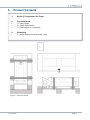
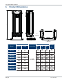
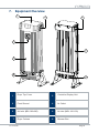
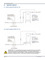
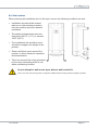
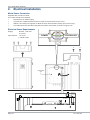
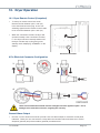
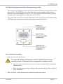
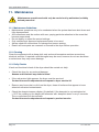
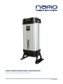
HEATLESS DESICCANT AIR DRYER
SERIES 2 DRYER USER GUIDE:
17-110-0120
nano-purification solutions.
Contents
1.
Page
General information
1.1.
1.2.
1.3.
1.4.
2.
Document introduction
Support and Manufacturers details
Warranty Guidelines
Packaging
General safety
2.1.
2.2.
2.3.
Intended Use
Personnel
Safe Handling
3
3
3
4
4
5
5
5
5
3.
Technical Description
6
4.
Technical Specification
6
5.
Product Contents
7
6.
Product Dimensions
8
7.
Equipment Overview
9
8.
System Layout
10
8.1.
8.2.
8.3.
Typical Installation NDL 060-090
Typical Installation NDL 100-130
Site Location
9.
Electrical Installation
10.
Dryer Operation
10.1.
10.2.
10.3.
10.4.
11.
Maintenance
11.1.
11.2.
11.3.
12.
13.
Page 2
Dryer remote control (if required)
Dryer Start-up
Monitoring dryer performance (Energy saving option)
Shutdown procedure
Maintenance guidelines
Cleaning
Daily checks
10
10
11
12
13
13
14
15
15
16
16
16
16
Servicing
17
12.1.
12.2.
12.3.
17
18
18
Guidelines
Procedures
Additional Kits
Troubleshooting
19
17-110-0120
1.
General Information
This manual is copyrighted, all rights reserved. It may not, in whole or in part, be copied, photocopied,
reproduced, translated, or reduced to any electronic medium or machine readable form without prior consent
in writing from nano-purification solutions. It may not be distributed through the internet or computer bulletin
board systems without prior consent from nano-purification solutions.
©2012 nano-purification solutions.
Product: Series 2 Desiccant Air Dryer
Document number: 17-110-0120
Issue: 002
1.1
Document Introduction
This manual provides factory prescribed installation and maintenance procedures for a nano-purification
solutions compressed air dryer. The procedures illustrated in this document are only to be performed by
authorized personnel. For further information regarding the procedures outlined in this document contact
nano-purification solutions before proceeding.
Read this document carefully before attempting to install or operate the dryer. This document should be
permanently available at the dryer installation site and be kept in an easily accessible place alongside the
dryer.
1.2
Support
Manufacturers Details
nano-purification solutions
nano-porous solutions limited
11330 Vanstory Drive
Huntersville, NC 28078
USA
Dukesway, Team Valley. Trading Estate,
Gateshead, Tyne and Wear,
United Kingdom, NE11 OPZ.
Telephone:
Fax:
Internet:
E-mail:
Telephone:
Fax:
Internet:
E-mail:
(704) 897-2182
(704) 897-2183
www.n-psi.com
[email protected]
+44 (0) 191 497 7700
+44 (0) 191 497 7709
www.n-psl.com
[email protected]
Annotations:
CAUTIONS: indicate any situation or operation that may result in potential damage to
the product, injury to the user, or render the product unsafe.
NOTES: highlight important sections of information where particular care and attention should
be paid.
17-110-0120
Page 3
nano-purification solutions.
1.3
Warranty Guidelines
All products are supplied with a 5 year manufacturer’s warranty from the date of purchase,
when purchased with an ES (Energy Saving) system and installed and maintained in
accordance with the manufacturers guidelines. Only genuine service parts should be used
and no modifications made. For further information please contact nano-purification solutions.
1.4
Packaging
All products are securely packaged in a specifically designed wooden packing box. The dryer
will be held in a horizontal position by wooden struts; using straps to secure the product to
the box base. The box top cover can be removed by removing the 4 fixing screws and lifting
off in one piece.
Damage to Packaging
• Check immediately to establish whether damage has occurred to the external packaging
and if the damage extends to the product inside.
• If there is damage to a product, contact the relevant supplier immediately.
In no circumstances must a damaged product be used in operation. Using damaged
products can lead to irreparable functional faults or cause serious physical harm.
The support packing box permits longitudinal stacking; however the central section
of the packing box should not be considered load bearing.
Page 4
17-110-0120
2.
General safety
For your own safety, when carrying out work on this product, all relevant
national safety regulations must be complied with relating to pressurized
and electrical systems.
2.1. Intended use of the Product
The dryer is exclusively intended for the treatment of compressed air, which is free from
bulk water, oil and solid matter constituents.
The product should be located within a building and protected. The dryer must be operated
only in accordance with the data on the rating plate. Any operations that do not comply with
those stated on the product rating label will render the warranty void.
This product is only designed to operate at pressures of between 58 - 232
psig (4 - 16 barg).
It is not suitable for pressures in excess of 232 psig (16 barg).
IMPORTANT: It is essential that the system into which the dryer is installed
is fitted with a pressure limiting/relief device. This device should be between the compressor and the dryer. The device must be set to prevent the
maximum working pressure of 232 psig (16 barg) from being exceeded.
No modifications must be made to the product. Any modifications may reduce the
operational safety of the product and invalidate the manufacturer’s warranty. This could
potentially result in damage to the product and serious personal injury.
2.2. Personnel
Only authorized, competent and trained personnel are permitted to work on this product.
This user guide is intended solely for such personnel and is to be used only as a reference;
it should not be used to replace conventional training.
2.3. Safe Handling
Please ensure the relevant safe engineering practices and handling procedures are
employed when handling, installing and operating this product. Ensure that the equipment
is depressurized and electically isolated prior to carrying out any of the scheduled
maintenance instructions specified within this user guide.
A suitable lifting aid must be used to minimize the risk of physical injury or
damage to the product.
In no circumstances must a damaged product be used in operation. Using
damaged products can lead to irreparable functional faults or cause serious
physical harm.
17-110-0120
Page 5
nano-purification solutions.
3.
Technical Description
The n-psi dryer uses the pressure swing adsorption principle of drying compressed air,
utilizing two identical columns each containing a hygroscopic desiccant bed.
•
Inlet filtration removes water, oil aerosols and particles (Inlet filtration supplied
separately).
•
Wet air enters the dryer through the inlet valve and is directed into one of the columns.
•
Each column contains a densely filled desiccant cartridge.
•
Air then passes through the desiccant cartridge where any remaining moisture is
adsorbed.
•
Simultaneously, a small amount of dry filtered air is counter flowed down through the
other desiccant cartridge and exhausted to atmosphere, removing the moisture and
regenerating the desiccant bed.
•
The dryer controller periodically switches columns after top end repressurization;
ensuring a continuous supply of dry air at constant pressure. The dryer can also be
controlled using a Zero Volt signal from the compressor. This energy saving mode
senses when the compressor is switched off and stops the dryer operation until the
compressor restarts.
•
The dry air passes out through the final particulate filter (<1micron/ISO8573.1 Class 2).
4.
Technical Specification
Specification
ISO 8573 - 2:2001 Quality Classes
Class 2: Water: -40°F (-40°C) PDP
Class 2: Dirt: 1μm
Minimum working pressure
58 psig (4 barg)
Maximum working pressure
232 psig (16 bar)
Power Supply
100 - 240v AC / 50 - 60Hz
Minimum inlet temperature
34.7°F (1.5°C)
Maximum inlet temperature
122°F (50°C)
Ambient Temperature
34-122°F (1-50°C)
IP Rating
IP54 / NEMA 3
Power
38W
Noise
<80dB (A)
•
Flow rate based on air inlet pressure of 100 psig (7.0 barg) and temperature of 95°F
(35°C).
•
For dryer performance at other inlet conditions or -100°F (-70°C) dewpoint
requirements, contact [email protected].
•
All dryers should be proceeded by a coalescing filter regardless of oil or oil free
applications, a nano MO1 grade coalescing filter must be installed on the inlet to the
dryer.
Page 6
17-110-0120
5.
Product Contents
1.
Series 2 Compressed Air Dryer
2.
•
•
•
Documentation
1 x User Guide
1 x Quick Start Guide
1 x Declaration of Conformity
3.
•
Packaging
1 x Dryer support base and box cover
Figure 1: Contents Layout
17-110-0120
Page 7
nano-purification solutions.
Product Dimensions
A
6.
8”
(200mm)
B
15”
(390mm)
Inlet Flow Rate
Model
Page 8
Nm3/hr
scfm
NDL-060
59
NDL-070
Connection
Dimension
B
C
A
Weight
lbs
(kg)
ins
(mm)
ins
(mm)
ins
(mm)
35
30
(734)
17
(440)
12
(295)
88
(40)
72
42
30
(734)
17
(440)
12
(295)
88
(40)
NDL-080
91
54
36
(914)
17
(440)
12
(295)
119
(54)
NDL-090
115
67.5
36
(914)
17
(440)
12
(295)
119
(54)
NDL-100
153
90
43
(1089)
17
(440)
12
(295)
141
(64)
NDL-110
183
108
49
(1239)
17
(440)
12
(295)
172
(78)
NDL-120
229
135
59
(1489)
17
(440)
12
(295)
209
(95)
NDL-130
306
180
72
(1839)
17
(440)
12
(295)
262
(119)
1” NPT
(Inlet & outlet)
17-110-0120
7.
Equipment Overview
1
4
5
2
7
3
8
6
1
Dryer Top Cover
2
Controller Display Unit
3
Front Shroud
4
Air Outlet
5
Air Inlet (NDL 060-090)
6
Air Inlet (NDL 100-130)
Dryer Column
8
Silencer Box
7
17-110-0120
Page 9
nano-purification solutions.
8.
System Layout
8.1. Typical installation NDL-060 - 090
8.2. Typical installation NDL-100 - 130
IMPORTANT: It is essential that the system into which the dryer is installed
is fitted with a pressure limiting/relief device. This device should be between the compressor and the dryer. The device must be set to prevent the
maximum working pressure of 232 psig (16 barg) from being exceeded.
Page 10
17-110-0120
8.3. Site Location
When selecting an installation site for the dryer, ensure the following conditions are met:
•
Installation site should be located
indoors on a flat surface protected
from the weather and other harmful
conditions.
•
The ambient temperature must not
drop below 33.8°F (+1°C) or exceed
122°F (50°C).
•
The installation site should be level
and able to support the weight of the
product.
•
Ensure sufficient space around the
product, to allow access for operation
and maintenance.
•
Take into account the noise generated
by the dryer exhausting while in use
when considering location.
Do not attempt to wall mount dryer without wall bracket kit.
*Note: Floor and wall mounting bolts not supplied. Additional wall mounting brackets supplied separately.
17-110-0120
Page 11
nano-purification solutions.
9.
Electrical Installation
Mains Power Connection
Supplied with 3 meters of cable:
If the cable needs to be replaced:
•
Disconnect from mains supply.
•
Unscrew the 4 x M5 cap head screws in order to remove the dryer top cover.
•
Slide 2 x door latch pins together to allow the dryer front shroud to swing open on the hinge.
•
This will expose the controller back plate and power connection (as shown in figure 8.A).
Electrical Power Requirements
Supply:
Input Current:
88 VAC - 264 VAC
47 -63 Hz
1.3 / 0.8A
(115/23 OVAL)
POWER
CONTROLLER
Controller Back
Plate
Fuse Holder
(T2A 250V)
Page 12
17-110-0120
10. Dryer Operation
10.1. Dryer Remote Control (if required)
•
To set up for remote control eco mode.
Remove the link between pins 1 and 4 (2)
in the electrical connector plug. A zero volt
switching signal from the remote control needs
to be connected between pins 1 and 4 (4).
•
When the connection is made, the dryer will
operate normally. If the connection is broken,
i.e. the dryer has been remotely switched off;
the dryer will also stop cycling and go into
standby mode, displaying “STANDBY” on the
display.
Electrical Connector
6 Pin Electrical Connector Configuration
1.
2.
3.
4.
Under no circumstances should external voltage/current be applied to pins 1 and 4,
damage to the controller will occur, negating the warranty.
General Alarm Output
•
Pins 2 & 3 on the electrical connector provide a zero volt alarm output for customer control panel
indication. These pins are connected to a relay within the controller which will close when service,
dewpoint (optional) and pressure alarm (optional) conditions arise.
17-110-0120
Page 13
nano-purification solutions.
10.2. Dryer Start-up
•
Ensure the dryer is securely hardwired into the power source.
Do not allow the dryer to flow air unless powered up, switched on and cycling. Resulting
effect could be desiccant contamination; requiring replacement desiccant cartridges.
•
Connect all pipe work.
•
Ensure the inlet operating pressure parameters are between 58-232 psig (4 - 16 barg).
•
Ensure the inlet air temperature is between 35°F - 122°F (1.5°C - 50°C).
•
Slowly open the inlet valve and allow dryer to pressurize.
•
Turn on the power to the dryer.
•
Open the outlet valve.
•
The dryer will display its status and commence normal operation. When the dryer is
powered up the display will show “initializing dryer” for approximately 20 seconds,
ensuring the dryer is in equilibrium state before commencing operation.
Page 14
17-110-0120
10.3. Monitoring dryer performance (Energy saving option)
•
The dew-point is displayed on the control panel. When the dew-point displayed is better
than -54.4°F (-48°C) PDP the dryer will switch into economy mode and stop cycling.
When the dew-point degrades to -43.6°F (-42°C) the dryer will restart cycling ensuring
the dew-point is maintained at or better than -40°F (-40°C).
•
If the dryer fails to achieve dew-point (falls below -22°F (-30°C)) the alarm output will be
indicated on the front screen and the remote alarm output will activate.
12.4. Shutdown Procedure
•
Close the inlet and outlet valves.
The dryer will still be pressurized! In order to depressurize the dryer;
ensure the dryer is isolated from the compressed air supply source:
•
•
Cycle the dryer at least twice to ensure the dryer exhausts and is completely
depressurized.
•
When fully depressurized the ‘clicking’ of the exhaust valves will be heard but
no air exhausted.
When the dryer is fully depressurized, isolate from the power supply.
17-110-0120
Page 15
nano-purification solutions.
11. Maintenance
Maintenance operations should only be carried out by authorized, suitably
trained personnel.
11.1. Maintenance Guidelines
• Maintenance operations only to be conducted when the system has been shut down and
fully depressurized.
• All connections must be undone with care, paying particular attention to the areas that
become pressurized.
• Do not modify or adjust the control settings.
• Only certified npsi approved replacement parts to be used.
• Always check all connections for leakage and secure seating.
• Ensure all loose parts are removed or secured to the dryer before operation.
11.2. Cleaning
Clean the equipment with a damp cloth only and avoid excessive moisture around any
electrical sockets. If required a mild detergent may be used, however do not use abrasives
or solvents as they may cause damage.
11.3. Daily Checks
Visual and functional check of the dryer should be carried out daily:
•
Check the dryer for any external damage.
Assess and eliminate any defects found.
•
If the red service light appears, the dryer must be serviced.
Contact the service department and request a dryer service kit.
•
Remove any loose dust or dirt from the dryer; clean all surfaces that appear to have
attracted unwanted contaminants.
•
Check the dewpoint sensor display (if installed). If the dewpoint is not maintained at
<-22°F the reading on the display will alternate with “dewpoint alarm” every 5 seconds.
The no-volt alarm will also activate.
Contact the service department and request a product service.
Page 16
17-110-0120
12. Servicing
Maintenance operations should only be carried out by authorized,
competent and suitably trained personnel.
12.1. Servicing Guidelines
•
Maintenance operations only to be conducted when the system has been shut down,
fully depressurized and isolated completely from the compressed air and electrical
supply.
•
Ensure the system is in a safe condition for maintenance to be carried out on.
•
Dismantle and assemble with care, paying particular attention to the areas that become
pressurized.
•
All gaskets removed during maintenance operations must be replaced with new gaskets.
•
Do not modify or adjust the control settings.
•
Only certified npsi approved replacement parts to be used.
•
Always check all connections / sealing faces for cleanliness and secure seating prior to
assembly.
•
Ensure all components are refitted to the product before operation.
•
Ensure the dryer is left operating in a safe working condition after completion of
maintenance.
17-110-0120
Page 17
nano-purification solutions.
12.2. Service Procedures
A dryer service should take place every 2 years or 12,000 hours of operation (whichever
occurs first). Service kits are available which include: replacement desiccant cartridges,
seals and valves. Please contact the manufacturer or distributor for service kit information.
•
Service A - 12,000 hours (or every 2 years) service.
Replace desiccant cartridges (NDK 060 (F)- NDK 130 (F))
Replace all gaskets and seals removed while servicing the dryer (included in relevant
service kits).
•
Service B - 24,000 hours (or every 4 years) service.
Service as above.
Replace exhaust valves. (EVK130)
Replace check valves. (CVK130)
Replace ICF valves. (IVF090 - IVF 130)
Replace Pilot valves. (PVK130) (NDL 100 - 130 Only)
•
Service C - 6,000 hours (or every 1 year) service.
Dewpoint sensor calibration service. (NSK-0130) – (ES MODELS ONLY)
MODEL
SERVICE A
Without Pre-filter Element
(With Pre-filter Element)
SERVICE B
SERVICE C
NDL - 060
NDK 060
(NDK 060 F)
IVK090 + EVK130 + CVK130
NSK-0130
NDL - 070
NDK 070
(NDK 070 F)
IVK090 + EVK130 + CVK130
NSK-0130
NDL - 080
NDK 080
(NDK 080 F)
IVK090 + EVK130 + CVK130
NSK-0130
IVK090 + EVK130 + CVK130
NSK-0130
IVK130 + EVK130 + CVK130 + PVK130
NSK-0130
NDL - 090
NDL - 100
NDK 090
NDK 090 F)
NDK 100
(NDK 100 F)
NDL - 110
NDK 110
(NDK 110 F)
IVK130 + EVK130 + CVK130 + PVK130
NSK-0130
NDL - 120
NDK 120
(NDK 120 F)
IVK130 + EVK130 + CVK130 + PVK130
NSK-0130
NDL - 130
NDK 130
(NDK 130 F)
IVK130 + EVK130 + CVK130 + PVK130
NSK-0130
12.3. Additional Kits
Wall Mounting kit: NMK-130
2 x Additional brackets supplied to support the dryer when wall mounting.
ES Upgrade Kit
Converts a standard dryer to an Energy saving model
Please refer to the Series 2 Dryer service guide for instruction regarding carrying
out a service.
Page 18
17-110-0120
13. Troubleshooting
Problem
Problem Caused
Solution
1.
Insufficient inlet pressure
1.
2.
Electrical Fault
2.
Inlet pressure min 58 psig (4 barg). If not adjust inlet
presure settings.
Ensure the power is on and the dryer control panel is
illuminated; check the dryer is cycling correctly.
Poor dew point
performance
3.
Moist or contaminated
desiccant
3.
Eliminate the cause of contamination. Replace desiccant
cartridges – do not re-use.
4.
Too high air consumption
4.
Ensure the performance of the dryer matches the
required system air consumption.
5.
Excessive inlet air temperature
5.
Check against technical specification.
6.
Insufficient purge air.
6.
Purge incorrectly adjusted. Consult service personnel to
adjust settings (Factory pre-set).
7.
Exhaust silencer blocked
7.
Consult service personnel.
Controller not functioning
8.
Ensure the controller is powered; check the on screen
column status to ensure it is powering the solenoid
8.
correctly
9.
Failure of dryer to
cycle
Controller not illuminated
10. Insufficient inlet pressure
11. Failure to de-pressurize when
cycling.
valves during normal cyclic operation.
Inlet pressure min 58 psig (4 barg). If not adjust inlet
presure settings.
10. Check power to unit & fuse.
11. Solenoid valve not functioning correctly; if there is power
9.
to the coil, replace valve. A correctly working valve
outputs an audible click when it energizes.
12. Outlet flow stops
12. Check inlet air supply.
13. Failure to initialize dryer
13. Switch off and restart dryer. Ensure dryer is pressurized
before powering dryer to allow dryer to initialize before
Constant
depressurization
14. Erratic air flow from exhaust
commencing operation.
14. Faulty or damaged valve; service required.
Reference to known issue
Opening the inlet valve too quickly
Valve should be opened slowly allowing the pressure to build up gradually.
Inlet/outlet head pipe
Diameter too small.
Pipe work unsupported.
Inlet pipe work from low point in system, allowing bulk water to collect and enter the dryer.
Electrical controller
Incorrect fuse fitted or fuse blown. Check the plug and fuse located on top of the controller
back plate inside the dryer front shroud.
Additional Items
Use of non-authorized components.
Untrained / unauthorized maintenance / installation personnel used.
Increase in air consumption without relation to the flow capacity of the dryer.
Purging the dryer with cleaning agents that could damage the components or the desiccant.
Covers removed or loose during operation.
Failure to carry out a service when indicated by the dryer service light.
Do not allow the dryer to flow air unless powered up, switched on and cycling. Resulting
effect could be desiccant contamination; requiring replacement desiccant cartridges.
17-110-0120
Page 19
nano-purification solutions
11330 Vanstory Drive
Huntersville, NC 28078
USA
Telephone: (704) 897-2182
Fax: (704) 897-2183
Internet: www.n-psi.com
E-mail: [email protected]