1
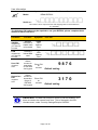
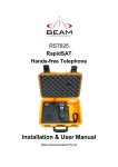
Satellite and Radio
Communications System
RST820 SatRADIO
User and Installation Manual
Beam Communications Pty. Ltd.
SatRADIO
RST820
User and Installation
Manual
Version 4
Beam Communications Pty Ltd
8 Anzed Court, Mulgrave,
Victoria, 3170, AUSTRALIA
Information furnished by Beam Communications Pty Ltd (Beam) is believed to be accurate and
reliable. However, no responsibility is assumed by Beam for its use, or for any infringement of patents
or other rights of third parties, which may result from its use. No license is granted by implication or
otherwise under any patent or patent rights of Beam. Beam reserves the right to change specifications
at any time without notice.
Copyright © 2007-2009 Beam Communications Pty Ltd. All rights reserved
Product name: RST820 User Manual
Manual revision: 04
Part Number: USRMAN002904
Release date: July 2009
Page 2 of 29
Package Contents
The RST820 package contents
1 x RST820 unit – including Iridium transceiver (internal)
1 x DC power cable
1 x Hex-Wrench for SIM cover
1 x Printed user manual
1 x Mounting Bracket Set (2 parts)
1 x Printed Iridium Antenna Guide
1 x RST970 Intelligent Handset
Optional Accessories
RST910 Iridium Helix Antenna
RST920 Iridium Bolt-mount Patch Antenna
UHF / VHF Antenna / cables
Various Antenna cable lengths
Iridium Antenna Tripod
See your Service Provider for pricing and availability of these optional accessories.
Page 3 of 29
User information
Please record your serial number here for future reference:
Model:
BEAM RST820
Serial no.:
This number can be copied from the white shipping label on the RST820 box
eg. 100A2800
The following PIN codes may be required to use your RST820, please complete these
details for future reference.
PIN Name
SIM PIN
Supplied by
your Service
Provider
PUK
Supplied by
your Service
Provider
User PIN
Supplied
here
Supervisor
PIN
Supplied
here
Function
Symptom
Unlocks
SIM card to
enable calls
to be made
Signal
LED
flashes
Red
Unlocks a
locked SIM
card
Signal
LED
flashes
Red
Allows
access to
user menu
of RST820
via log port
Allows
access to
supervisor
menu of
RST820
via log port
Enter PIN
on
console
Enter PIN
on
console
Your PIN
9876
Default setting
3170
Default setting
SIM PIN Note: The SIM PIN prompt on power-up can be disabled, so it
does not need to be entered each time. This is changed in the DPL
Handset menu, under “Security Settings/Require SIM PIN”.
Page 4 of 29
Contents
ABOUT YOUR RST820 SATRADIO .................9 SYSTEM POWER UP ..................................... 13 OPERATING THE TWO-WAY RADIO ............... 13 OPERATING THE SATELLITE MODULE ............ 13 Autodial Mode ........................................ 13 USING A RADIO HANDSET – DTMF MODEL ... 14 MAKING A CALL ............................................ 14 ACCESSING QUICK (SPEED) DIALS FROM RADIO
HANDSET .................................................... 15 ANSWERING A CALL ..................................... 15 Answering on a Radio ........................... 15 Auto Answer .......................................... 15 INTELLIGENT HANDSET MODE (IF FITTED)...... 16 TRANSFERRING INTELLIGENT HANDSET MODE
TO RADIO MODE .......................................... 16 Autodial Mode - Quick Dial .................... 17 Setting up Autodial Mode ...................... 17 VOX OPERATION – UNDERSTANDING THE
OPERATION ................................................. 17 LED STATUS ............................................... 18 Call (Orange) ......................................... 18 Signal ..................................................... 18 INTELLIGENT HANDSET RST970 .................. 19 INSTALLING THE ANTENNA - REFER TO
SEPARATE GUIDE ......................................... 19 USING RST820 SATRADIO .........................10 DATA COMMUNICATIONS ......................... 20 PACKAGE CONTENTS ..................................3 THE RST820 PACKAGE CONTENTS .................3 OPTIONAL ACCESSORIES ................................3 SIM PIN ................................4 PUK .......................................4 Supplied by your Service
Provider .................................4 User PIN ................................4 Supplied .............................4 here ....................................4 Default setting ......................4 Supervisor PIN ......................4 Supplied here ............4 Default setting ......................4 SAFETY INFORMATION ................................6 Conventions in this Manual ......................6 Exposure to Radio Frequency Signals .....7 ABOUT BEAM COMMUNICATIONS .............8 GETTING STARTED.....................................11 Tools required ........................................11 RST820 CONNECTOR OVERVIEW.............12 Connecting the Antenna Cable ..............12 Connecting the Power Cable .................12 Connecting the Radio Interface Cable ...12 Connecting to the Comm Port (if required)
................................................................12 Connecting to the Log Port (if required) .12 RST820 OPERATION ...................................13 Page 5 of 29
RS232 SPECIFICATION ................................ 20 PHYSICAL CONNECTION ............................... 20 INTERNAL RS232 PORT SIGNAL SUPPORT AND
HANDSHAKING ............................................. 21 RS232 PORT ELECTRICAL PARAMETERS ...... 21 RADIO INTERFACE ....................................... 22 TROUBLESHOOTING ................................. 23 CONFIGURATION – TECHNICAL NOTES . 25 SPECIFICATION SUMMARY ...................... 27 BEAM WARRANTY CONDITIONS ................... 29 Safety Information
IMPORTANT! Please read the following information carefully before
installing and using this BEAM equipment. Failing to follow instructions may
compromise the safety of the product and may result in personal injury
and/or equipment damage. Please consult your supplier if you have any
further questions.
Your RST820 is a low power radio transmitter and receiver, when ON, it receives and sends out
radio frequency (RF) signals.
The design of your RST820 system complies with international safety standards.
Refer to the appropriate section of this RST820 Installation & User Manual for additional safety
information.
Warning:
Do not open equipment. There are no user-serviceable parts inside.
If a DC power supply is to be used, its output must comply with the Safety
Extra Low Voltage (SELV) requirements of IEC60950.
All connectors must only be connected to equipment ports which comply with
the Safety Extra Low Voltage (SELV) requirements of IEC60950.
Conventions in this Manual
Warnings, cautions and notes appear throughout this manual and are represented by following
conventions:
Warning: This symbol and associated text indicate a warning note
providing information to prevent personal injury or damage to
equipment.
Note: This symbol and associated text indicate a note providing
general operating information.
Interference: All wireless phones may get interference, which could
affect performance.
Record: Write details of your unit for easy reference when required.
Ideal for troubleshooting.
Page 6 of 29
Exposure to Radio Frequency Signals
Your wireless mobile telephone is a low power radio transmitter and receiver. When it is ON, it
receives and also sends out radio frequency (RF) signals.
International agencies have set standards and recommendations for the protection of public
exposure to RF electromagnetic energy.
•
International Commission on Non-Ionising Radiation Protection (ICNIRP) 1996
•
Verband Deutscher Elektrotechniker (VDE) DIN-0848
•
United States Federal Commission, Radio Frequency Exposure Guidelines (1996)
•
National Radiological Protection Board of the United Kingdom, GS 11, 1988
•
American National Standards Institute (ANSI) IEEE. C95. 1-1992
These standards are based on extensive scientific review. For example, over 120 scientists,
engineers, and physicians from universities, government health agencies, and industry reviewed the
available body of research to develop the updated ANSI standard.
Your RST820 utilises the Iridium L-Band satellite Transceiver, which is a low power radio transmitter
and receiver. When it is ON, it receives and sends out radio frequency (RF) signals.
The SatRADIO Portable system contains a Li-Ion battery unit with high energy density. Do not
disassemble, puncture, throw, drop, crush, bend, or modify this battery unit. Do not charge the
battery while on an airplane.
Store the system in a cool and dry area.
It is important to monitor the heat inside the unit in the event that the case lid is closed during
operation.
Do not obstruct the main panel vent holes, or to the rear of the panel, as this may cause
overheating.
Do not submerge the system in water.
Do not place foreign metal objects or debris in the system. If debris falls into the system, please
return to factory for service.
Page 7 of 29
About BEAM Communications
BEAM Communications, is an authorised manufacturer of Iridium Satellite products.
BEAM develops subscriber products that utilise the Iridium satellite network of Low Earth Orbit
satellites, known as LEOs. The Iridium network is extensively used around the world by commercial
enterprises and defence agencies.
BEAM products address the needs of individuals, communities, government agencies and the
corporate sector, providing voice and data access without the need for traditional wire-line or mobile
phone infrastructure.
As the Iridium satellite network is global, BEAM products address global markets, across the
spectrum of rural and remote users, including households, motor vehicles, telemetry, maritime and
emergency services.
BEAM Communications Pty Ltd
8 Anzed Court, Mulgrave,
Victoria, 3170, AUSTRALIA
Web:
Info:
Support:
Tel:
Fax:
www.beamcommunications.com
[email protected]
[email protected]
+61 3 8588 4500
+61 3 9560 9055
Page 8 of 29
About your RST820 SatRADIO
The RST820 is a Portable Radio over Satellite system for connecting a radio network to a base
station or phone call party over the Iridium network.
The RST820 extends your existing Radio network using an Iridium satellite link with an easy-todeploy portable solution in a self-contained rugged carry case.
The RST820 SatRADIO works by becoming another participant in your local radio net, with the
other end of the satellite connection anywhere in the world: your central base, or another remote
radio net.
The SatRADIO provides useful features such as field radio-handheld dialling (via DTMF tones) and
sends acknowledgement tones back over the radio to indicate current state. It can be set up to
operate in a number of ways best suited to your situation, such as auto-dial which automatically reestablishes the Satellite link if the phone call drops out. The system can also provide the ability to
auto answer any incoming call.
The SatRADIO can be incorporated into any suitable two-way radio system. This radio equipment
is supplied separately and configured separately for VHF or UHF.
The system is powered from a 10 to 32V DC source. It also provides a data connection and
Satellite SMS access.
The complete RST820 provides total peace of mind, flexibility and a rapid deployment solution for
government, military, and emergency service applications.
Page 9 of 29
Using RST820 SatRADIO
The RST820 is software configurable to operate in a number of ways to best suit your
situation. This mostly relates to how the satellite call is initiated.
•
Auto-answer. Regardless of any locally initiated call out operation, the SatRADIO
can be setup to auto-answer an incoming call. Once answered the remote caller
participates in the local radio net.
•
Manual-answer. An incoming satellite call causes an intermittent ring tone to be
transmitted out to the local radio group. Any member of the local group can answer
the call by sending a DTMF-0.
•
Auto-dial last number (Re-Dial mode). When the SatRADIO and the radio are both
on, the unit will immediately try to call the last number that was dialled on the Iridium
handset. This mode is most useful for emergency services where a quick and easy
method of connecting the local net to central command is required. If the call ever
drops out, the SatRADIO will attempt to redial the number again.
•
Auto-dial fixed number. In cases where only one remote number is ever to be called,
instead of calling the last dialled number, the unit can always dial a user-preset
number.
•
Manual-dial. Any member of the local group can request a satellite call using DTMF
dialling on the radio handset. A user PIN entry (default 9876) is required prior to the
phone number entry to add security. A manual call can be hung-up either at the
remote end, or by sending DTMF-0.
•
Manual-quick-dial. Similar to manual dial, except that a quick dial number is called
instead of the full phone number. 10 quick dial numbers are available and are called
by using the sequence PIN 0->9,*, to select the number.
•
Handset Call. The Iridium handset (optional) can be used to make a satellite call.
Audio is routed to the handset rather than the radio channel.
The SatRADIO always give priority to the local group communications. If a local user is
transmitting at the time, even if the remote person speaks, the SatRADIO will not key up
the transmitter till the local person stops transmitting.
Page 10 of 29
Getting Started
The RST820 requires that a valid Iridium or Telstra Mobile Satellite SIM card to be
installed. This is not included in the RST820 kit and you should consult your place of
purchase is you do not have an active SIM card enabled to make Iridium Satellite calls.
Warning: To prevent possible damage, make sure the RST820
system is completely switched OFF before installation.
Tools required
•
•
Philips-head screwdriver
Allen Key (supplied)
Note: Be careful to ensure that when you are removing or
installing the antenna or adaptor that the handsets power is
turned OFF. The handset should not be turned on until after the
connector cable is attached also.
Step 1: Ensure the System is switched off.
Step 2: Open the case lid.
Step 3: Using a
Step 4: Remove
Step 5: Use the
Step 6: Replace and
Philips screw driver,
remove the black
steel cover plate.
next screw, and slide
back the cover.
Allen Key, and
remove the 2 sockethead screws, and
insert the SIM card.
re-fit all screws and
covers.
(HINT: carefully using
the hex-wrench can
help slide the plastic
SIM holder)
Page 11 of 29
RST820 Connector Overview
Connecting the Antenna Cable
Plug the antenna cable into the TNC antenna jack located on the rear panel of the RST820 case.
Ensure that the specified cable being used does not exceed the Iridium maximum-loss rating of 3dB
to ensure maximum performance of the terminal. Refer to your Service Provider for full details or to
purchase an approved cable if using a cable other than the magnetic mount antenna included.
Connecting the Power Cable
Plug in power cable into the 2-pin power socket located on rear panel of the RST820 case. Attach
the free ends to the correct terminals of the DC power supply, being careful to observe polarity.
Connecting the Radio Interface Cable
Connect the cable to the HD-15 connector labelled Remote Status Indicator. Refer to the Radio
Interface connection table for pin designations and signal requirements.
Connecting to the Comm Port (if required)
Connect a PC/Laptop to the Comm Port to make dial-up modem calls. The Iridium data speed is
2400bps, and can be as high as 10kbytes if using Direct Internet compression. A data call cannot
be made at the same time as a voice call.
Connecting to the Log Port (if required)
Connect a PC/Laptop to the Log port to use the Beam Management System. The Log Port should
only be used for configuration and control of the terminal equipment.
Note: Both ports are wired DCE and require a straight through cable.
Page 12 of 29
RST820 Operation
System Power up
After installation has been completed, the RST820 system is now ready to be switched on.
To turn on the system:
1. Apply power to the attached radio and RST820.
2. Wait for the Signal LED to stay solid green or orange or, the DPL Satellite
Handset (if fitted) to show registered status. This will typically take 40 to 60
seconds.
3. A call can now be attempted.
Operating the Two-Way Radio
The RST820 is required to be installed with a Two-way radio that will be to the compatible
specification. The Radio component needs to be tuned to your desired channels to ensure
that it can communicate with other radios within your user group. Tone or CTSS squelching
schemes should be programmed as required.
To ensure optimum performance check the following
1. Ensure the Radio component is switched on and initialised.
2. Ensure that the other Radios you want to interface with this unit are on the same
frequency as the RST820 main terminal.
3. Test that from the Radio Control handset you can talk to the other radios on the
same Frequency / Channel. If not, ensure that the correct Channel has been
selected and any required CTSS or tone squelch has been set up correctly.
4. If you do not believe that you have communications between your Radio’s
consult your radio provider to ensure the unit has been programmed to your
required channel set up.
Operating the Satellite Module
Autodial Mode
This mode enables the RST820 to continuously keep connected into a preset destination
(phone number). This is ideal for emergency or disaster recovery situations when the
terminal may be being used as a primary communication tool or a replacement for a Radio
link that is down.
Page 13 of 29
Using a Radio Handset – DTMF Model
Using a DTMF compatible Two-way Radio it is possible to make or receive a call over the
satellite network on the Radio device. To make a call from a Radio handset a PIN is
required. This is configurable to protect against unauthorised calling.
Making a call
1. Ensure that the Autodial switch on the RST820 terminal is turned OFF (pin 15
connected to GND) as it is not possible to override this autodial active mode.
This function is enabled from the Dial input of the Remote Status Indicator port
and is either an external switch or a hard-wired link to ground in the connector.
2. Ensure the radio handset is on the same frequency as the main radio unit.
3. Ensure the Satellite & Radio units are both powered ON
4. Whilst pressing the transmit button of the radio enter the PIN (default 9876) to
access the system.
a. If PIN accepted a couple of acceptance pips are issued to indicate it is now ok
to dial the phone number.
b. If the PIN number fails the handheld user receives a rising crescendo tone.
c. The access (after the PIN has been entered) times out after approx 10
seconds, after which the PIN would need to be to be re-entered.
d. In the event you have trouble entering the correct PIN wait 20 seconds in
between tries to allow the unit to reset.
e. Remember that it is not possible to transmit DTMF tones whilst another party
is transmitting on another radio in the group.
5. Once the acceptance pips are heard depress the transmit button and enter the
full number you wish to call, and then release the button.
a. Usually the transmit button of the radio needs to be pressed the entire time
the number is being entered In order to transmit the tones to the base unit.
b. If the dialled number seems to be a valid format acceptance pips will be
transmitted to the handheld from the satellite base.
c. If the number is invalid then a FAIL tone is sent; a long, low, beep.
6. Progress calling tones will be heard whilst the call connects, if the number was
incorrect or the satellite network is not available a busy tone will be heard
through the radio network.
7. Hanging up the call: If the call was manually dialled or was incoming, it can be
hung-up by the handheld user by simply pressing the transmit button of the
radio followed with a DTMF- 0 (zero).
NOTE: Transmission of any DTMF tones will only transmit whilst the
transmit button of the two-way is depressed and there is no other
activity on the Radio channel
Page 14 of 29
Accessing Quick (Speed) Dials from Radio Handset
The quick-dial mechanism can also be used if any of the quick-dial numbers have been
setup in the SatRADIO.
Dial PIN, then a digit between 0->9 then *, to identify the quick dial number.
The quick dials can be programmed only using the Beam Management System when
connected with a PC to the Log port.
The quick dials are accessed in the following way:
1. Ensure the quick dial locations have been programmed in the main satellite terminal
2. Enter the PIN from the handset as per above instructions
3. Once acceptance pips received enter a Quick Dial location digit between 0->9 then *,
obviously only those locations that have been preconfigured can be called in this
manner.
E.G. if you enter your PIN followed by 2 * this would dial the preset Quick Dial
in location 2.
Answering a call
There are two ways of answering a call on the two-way radio, by either using the DTMF
controls on the handheld to accept the call or if you want all incoming calls answered
automatically then this can be configured on the terminal.
Answering on a Radio
A RING signal will be intermittently transmitted on the Radio channel and the handheld user
can reply to answer the incoming call by sending a DTMF-0 to answer the incoming call.
Note: The DTMF-0 must be sent in the gap between rings for it to be heard by
SatRADIO.
Auto Answer
The firmware can be set to automatically auto-answer an incoming call as long as the Radio
is ON. This is the default setting.
Note: Auto answer cannot work concurrently with Autodial being ON
Page 15 of 29
Intelligent Handset Mode (if fitted)
This mode enables you to make a satellite telephone call using the Intelligent handset of
the terminal. Take the handset off the cradle and make a satellite call as though your were
using a typical cellular telephone.
To make a satellite call:
1. Remove the handset from the cradle by pushing the handset up
2. Enter the phone number you wish to call.
a. Consult your Satellite SIM provider for standard dialling instructions as this
may vary depending on the type of satellite SIM used
3. Once the number has been entered press the OK button to commence calling
4. To terminate the call simply press C, or return the handset to its cup.
5. To adjust the volume in call simply press the arrow up/down on handset.
Transferring Intelligent Handset Mode to Radio Mode
It is possible to make a call (or answer a call) on the Intelligent Satellite handset and then
transfer the call through to the Radio network. You MUST connect the Dial input signal
to a toggle-switch or other form of relay connection to change between input
voltages.
1. Answer an incoming call on the Intelligent Handset keypad, or make a call
on the Intelligent Handset.
2. During the call, activate the “Dial” input by placing it in the ENABLED
(positive + voltage) position (for greater than 1sec). The call will now be
routed to the radio audio circuit.
3. Toggle the switch for the “Dial” input by switching it back to the DISABLED
(GND voltage) position. This does NOT hang up the call.
4. End the call by either transmitting a DIGIT-0 on the radio network, or by
returning the Intelligent handset to the cup, or pressing “end call” on the
Intelligent Handset.
5. Repeat steps above for transferring the next call when required.
NOTE 1: “AutoDial” (in Beam Management Settings) must be disabled.
NOTE 2: “Auto Answer” (in Beam Management Settings) must be disabled.
NOTE 3: If the “Dial” input remains in the ENABLED (+ve) position after the call is ended,
this instructs the RST820 to operate in “auto-redial” mode. It will attempt to automatically
call the last number that was originated from the RST820 system. This is a similar function
(but not the SAME) to the “AutoDial” mode which is instead enabled from the Beam
Management System.
Page 16 of 29
Autodial Mode - Quick Dial
This mode enables the RST820 to continuously maintain a phone call link to the number in
Quick Dial position “0” (if configured). This is ideal for emergency or disaster recovery
situations when the terminal may be being used as a primary communication tool or a
replacement for a Radio link that is down.
As soon as the SatRADIO is powered on and registered, the RST820 will attempt to
automatically call this number, and maintain this call by redialling automatically.
Setting up Autodial Mode
The Quick Dial Autodial feature uses the Quick Dial memory location “0” of the satellite
terminal. This enables a fixed telephone number to be programmed for a permanent
application where the SatRADIO is always required to call the same location.
These settings are PIN protected using the Beam Management System and can only be
changed by an authorised person.
VOX operation – Understanding the operation
Once the voice call is in progress, the base operator can hear all traffic on the Radio
channel (assuming the SatRADIO has been setup with Selcall or CTSS compatible with the
local radio user group).
Whilst the radio is receiving a signal, the base operator cannot be heard (local priority). If
the channel is clear, when the operator speaks the SatRADIO transmits on the channel.
The threshold of this voice operated switch (VOX) can be adjusted, as well as the tail (how
long it keeps transmitting after the remote speech stops).
The status indicators are located on the main panel of the RST820.
Page 17 of 29
LED Status
Call (Orange)
Indicates the status of the call, either a data or voice call. The LED indicates:
• In Call (Flashing)
• Waiting to connect (constant)
• Incoming call (cadence flash)
• Data port active (constant)
Signal
The Signal Strength LED gives an indication of how strong the signal is from the Iridium
network at your location. This LED displays different colours to indicate the strength of the
RF (Radio Frequency) signal and different on/off conditions to indicate the terminal status.
Indictor colour
Signal strength
Flashing
RST820 is registering with the network –
please wait
Green
Strong
Orange
Acceptable
Red
No signal, check installation
The Signal Strength LED reading will vary in status in relation to the quality of the Signal
being received by the terminal. There are many factors that will affect the signal strength
including, local RF interference, poor antenna cabling or exceeding the 3DB loss limit, poor
line of sight or other environmental conditions affecting signal penetration to the antenna
system.
Page 18 of 29
Intelligent Handset RST970
The RST820 is capable of supporting voice
services on the Iridium network through the use of
the DPL Intelligent handset. The Intelligent
handset enables you to access Voice and SMS
services over the Iridium network in conjunction
with the RST820 terminal interface.
A Beam Communications approved extension
cable to the Intelligent handset is optionally
available.
The DPL Handset is inserted and removed from
the cup by pushing forward against the springloaded arch.
A: The RST820 is only compatible with the second generation (DPL bus)
type Iridium Intelligent handset. The Intelligent Handset should only be
disconnected and or connected when the power is OFF.
B: Inserting the DPL handset back in the cup WILL terminate an active call,
(unless the magnet internal to the cup is physically removed: doing so
voids the warranty of the Intelligent handset cup).
Installing the Antenna - refer to separate guide
See the specific “Iridium Antenna Guide” or visit www.beamcommunications.com
Page 19 of 29
Data Communications
A 9 pin serial communications port (Comm Port) is provided for data communications over
the Iridium satellite channel. Data calls cannot be made when the terminal is busy in a voice
call with the handset or radio.
The interface is wired DCE, so appears as a normal Hayes modem to a computer.
Standard AT Hayes commands can be used to initiate a Data call using this port. Refer to
RST100 AT command reference.
Asserting DTR on this port precludes use of the SatRADIO for voice services, unless the
Activity timeout is also used. Refer to the RST100 Manual Data Connections for more
information on sharing voice and data services.
RS232 Specification
The RST820 is provided with two RS232 serial ports for configuration (Log Port) and data
(Comm Port) connection. Both are 9-pin D-type (female) sockets, wired DCE for connection
to a standard PC with a 1:1 cable.
Physical Connection
The pin-out of both connectors is described in the following table:
Pin
Signal
Direction
Description
1
DCD
RST¼PC
Data Carrier Detect
2
RXD
RST¼PC
Received Data
3
TXD
PC¼RST
Transmitted Data
4
DTR
PC¼RST
Date Terminal Ready
5
GND
6
DSR
RST¼PC
Data Set Ready (CTS and DCD)
7
RTS
PC¼RST
Request to Send
8
CTS
PC»RST
Clear to Send
9
RI
RST¼PC
Ring Indicate (7.5V on Log port)
Signal Ground (Common)
Page 20 of 29
Internal RS232 Port Signal Support and Handshaking
On the Comm port, DCD and DSR output signals are related to DTR input and CTS is tied
to RTS as shown. The Comm port supports full software XON/XOFF handshaking on data
(AT commands bypass this as standard for Hayes modems) or full hardware handshaking
on RTS/CTS with DCD carrier indication.
The Log port has no software handshaking support and hardware handshaking is loop-back
only since the command set requires a minimal buffer.
RS232 Port
Comm Port
Log Port
DCD
DCD = DTR
RXD
RXD
TXD
TXD
DTR
DTR
DSR
DSR = DTR
RTS
RTS
CTS
CTS = RTS
RI
RF=HIGH
RS232 Port Electrical Parameters
The Comm and Log Ports conform to the RS232 interface specification with the following
parameters, however the Log Port communicates only at 9600:
Parameter
Specification
Communication Rate
220 to 115,200 Baud
Protocol
1 start bit, 8 data bits, no parity, 1 stop
bit, asynchronous.
Voltage Levels and
Sensitivity
RS232 compliant
Page 21 of 29
Radio Interface
The Remote Status Indicator port provides audio and control/status for interfacing to an
external radio. (Cables can be supplied when ordered extra).
Pin No.
Signal
Direction
Function
1
nPTT
Output
2
Sat UP
Input
Rx Audio (unbalanced) from radio for satellite uplink.
1V nom.
3
POWER LOST
Output
Indicates a loss of 7.5V supply regulation. Closed on
Fail relay contact
4
nEXT
Input
5
Call LED
Output
6
PWR
Input
7
GNDi
8
HIGH TEMP
Output
Satellite has not maintained registration. Closed on
Fail relay contact
9
Signal Led Red
Output
Indicated the condition of the RED Signal LED. 7.5V
on, <3V off. Not isolated
10
GND
11
nRSQ
Input
12
Sat DOWN
Output
Satellite downlink audio (unbalanced) to radio
transmitter. 1V nom.
13
HIGH TEMP
Output
Internal PCB temperature sensor has reached a predefined maximum. Closed on Fail relay contact
14
AUX
Input
Normally high (7.5V). Pull below 2V to activate
15
Dial
Input
Enables auto-dial a pre-defined number, or used for
call transferring from DPL handset to radio. Pull below
2V to disable. Toggle to >12V to enable.
Key transmitter. Active low. Requires external 15K
ohm pull-up. Max 16V
Normally high (7.5V). Pull below 2V to activate
Indicated the condition of CALL LED. 7.5V on, <3V off.
Not isolated
Enables SatRADIO functionality. 10-32V
Isolated GND. This is the common for the relay
contacts, Sat UP, Sat DOWN, PWR, nPTT and nRSQ
(This can be used as return GND connection to
disable “Dial” signal).
Received audio squelch signal (gated RSSI). Active
low
The minimum required signals are GNDI, Sat UP from the radio receiver audio, Sat DOWN to the
radio transmitter audio, nPTT and nRSQ. The PWR input is connected to the DC supply or a 1032V source. The DIAL input must be connected either directly or by switch to the GND (not GNDI)
signal to prevent autodial / redial modes.
Page 22 of 29
Troubleshooting
This chapter provides information to help you troubleshoot problems you may encounter while
running the RST820.
Q
A
No lights on RST820
Check that DC power cable is correctly attached and the external supply is
adequately specified.
Q
A
No dial tone
Check if a data call is in progress and power is connected and equipment is in a
normal state
Q
A
Cannot make call, two tone signal heard
Phone requires a PIN or PUK, refer to the handbook
Q
You can’t make calls.
Check that the antenna is properly mounted.
A
Do you have a clear view of the sky?
Did you enter the number in international format?
All calls made from the Iridium System require a special calling sequence;
please refer to your Service Provider for these details.
Check the signal strength meter. If the signal is weak, move the antenna to a
more open area.
Check the Network Selection settings.
Check your Operator coverage map.
Is R e s t r i c t e d displayed? Check the Call Barring setting.
Has a new SIM card been inserted?
Q
A
You can’t receive calls
Check to see that your phone is powered on.
Check the antenna. Is it properly mounted?
Do you have a clear view of the sky?
Check the signal strength. If the signal is weak, move the vehicle to a more
open area.
Check the Call Forwarding and Call Barring settings.
Q
A
You can’t make international calls.
Have you included the relevant codes? Press and hold the (+) key to display the
international dialling prefix (+), and then enter the appropriate country code,
followed by the phone number.
Q
A
Your PIN is blocked
Enter the PIN unblocking key (PUK1) or contact your service provider
Page 23 of 29
Q
A
Your PIN2 is locked.
Enter the PIN2 unblocking key (PUK2) or contact our service provider.
Q
A
Your SIM card won’t w ork.
Is the card inserted the correct way?
Is the gold chip visibly damaged or scratched? Return the card to your
service provider.
Check the SIM and phone contacts. If they are dirty, clean them with an antistatic
cloth.
Q
A
You can’t cancel call forwarding or call barring
Wait until you are in an area with good network coverage and try again.
Q
A
Your terminal has the SIM card inserted but the display says: Enter PUK
Enter the PIN unblocking key (PUK1) or contact your service provider
Q
A
Your PIN is blocked
Check Card or Insert Card.
Check the card is inserted correctly
Check the contacts of the card are clean
Clean the chip with a soft cloth
See your Service Provider if continues
Q
A
Can make a call however no audio coming via the Radio
Check the Radio is configured correctly
Check the CTSS/Channel Selcall
Page 24 of 29
Configuration – Technical Notes
Configuration of the SatRADIO can be performed by a user with sufficient privileges, and is
usually required on initial installation to program the way the unit is to operate and adjust
levels.
Configuration is simple and can be done with any PC. An RS232 serial connection is
required which can be either provided by the PC itself, or a USB->Serial converter. The
serial port is connected to the CONFIG port on the SatRADIO with a direct 9 pin serial
cable. A utility called “BMS” (Beam Management System) provided on the CD should be
installed on the PC. You will need a supervisor PIN in order to be able to use the BMS.
There are many items that can be programmed with the BMS. Many relate to a normal RJ11 phone installation rather than a SatRADIO and are not relevant, but here are some that
are particularly relevant to a SatRADIO installation:
• Supervisor PIN: This 4 digit PIN number can be changed to protect access to the
configuration. Make sure you remember the new PIN though, and be able to supply it if
ever you need to contact Beam Support.
• User PIN: This 4 digit PIN is used to access to the call records, and is also the Manualdial PIN required to be entered on a radio handset prior to the phone number when
using DTMF calling.
• Ring tones: If you are using manual-answer, the 2nd ON and OFF times are very
important. The ON time determines how long the ring tone is, the OFF determines how
much time in between rings a user has to hit DTMF-0. Note that a DTMF-0 cannot be
sent to the SatRADIO while the ring tone is being transmitted as the SatRADIO is halfduplex like any radio.
• Dial Tone: The configuration of this tone is used for the acceptance pips on SatRADIO.
• Unavailable Tone: The configuration of this tone is used for the Fail/No-Service tone on
the SatRADIO.
• Local Ring: If set then manual-answer using DTMF-0 is configured. If clear then autoanswer incoming calls is configured.
• DTMF timeouts: Usually set longer for SatRADIO than a normal phone installation
because it’s harder to dial on a handheld keypad than a phone. These time outs effect
how long it takes a call to be cleared after the last DTMF key is pressed
• Auto Dial: If set, the SatRADIO will auto-dial the number in Quick-Dial-0 location when
the radio is On, and the Dial input signal is enabled. If clear then the last number dialled
on the Iridium handset will be called (re-dial mode) when Dial input signal is enabled, or
manual PIN protected DTMF dialling is available when Dial input signal is disabled.
• Manual Quick Dial: It is possible to configure up to 10 quick-dial memories with phone
numbers for use when manual DTMF dialing from a handset. There are 10 quick-dial
memories, and these can be called using the sequence: PIN0->9,*,
Page 25 of 29
• Gains, Upstream, Downstream & Tones may need to be optimised for a particular
radio. Different radio manufacturers have different line levels on their radio interface
connections, and therefore to get the best audio these gains may need to be adjusted.
• VOX threshold. When the remote side speaks, a voice activity detector (VOX) is used
by the SatRADIO to key the SatRADIO transmitter. Small adjustments to this voice
detector are possible using the SLIC On (activity level required to key-up) and SLIC Off
(activity level required to drop under to key-down once keyed up) parameters.
Page 26 of 29
Specification Summary
Electrical
Input Power
10-32VDC 5A
Power Consumption (Average Power)
Standby Mode
5W
Talk/Transmit Mode
Receive 7W
Transmit 7W
Intelligent Satellite Handset
Voltage
+12VDC
Audio
Line level
Digital Control
115kbps RS232
RF Interface (L-Band Transceiver)
Frequency range
Average Power
1616MHz to 1626.5MHz
7W during a transmit slot (max)
Average Power
Receiver Sensitivity
0.6 W during a frame (typical)
Receiver Spurious Rejection at offsets
> 1 MHz (typical)
60 dB
Duplexing method
TDD (Time Domain Duplex)
Oscillator stability
±1.5ppm
Input/output impedance
50 Ohms – TNC F Connector
Multiplexing method:
TDMA/FDMA
-118.5 dBm at 50W (typical)
Page 27 of 29
Environmental
Operational Temperature
-30°C to +60°C
Storage Temperature
-40°C to +80°C
Vibration
MIL-STD-810F 514.5
Temperature
MIL-STD-810F 501.4
Humidity
MIL-STD-810F 507.4
Product Sealing
IEC529 rating IP54
Certification
RST820 EMC/EMI Compliance
EN61000-6-2, EN61000-6-4, EN61000-3-2, EN61000-33, FCC Part 15B Class A, C Tick CISPR22 Class A
Additional Certification for Iridium Transceiver:
The following harmonised standards have been applied to the design of the L-band transceiver:
Standard
Description
EN 60950-1:2001
Information technology equipment – Safety – Part 1: General Requirements
EN 301 489-20V1.2.1 (200211)
Electromagnetic compatibility and Radio Spectrum Matters (ERM);
EN 301 489-01v1.4.1 (2002-08)
Electromagnetic compatibility (EMC) standard for radio equipment and services.
ETSI EN 50360:2001
Product standard to demonstrate the compliance of mobile phones with the basic
restrictions related to human exposure to electromagnetic fields (300MHz to
3GHz)
ETSI EN 301 441 V1.1.1 05/2000 Satellite Earth Stations and Systems (SES); Harmonised EN for Mobile Earth
Stations MESs)
Page 28 of 29
BEAM Warranty Conditions
BEAM Communications gives this express warranty (along with extended warranty endorsements,
where applicable) in lieu of all other warranties, express or implied, including (without limitation),
warranties of merchantability and fitness for a particular purpose. This constitutes our sole warranty
and obligation with regard to our products as well as the Customer’s sole remedy.
BEAM Communications expressly disclaims all liability and responsibility for any special, indirect or
consequential damages or any further loss of any kind whatsoever resulting from the use of our
product(s). The Customer’s sole and exclusive remedy and the limit of BEAM liability for any loss
whatsoever, shall not exceed the purchase price paid by the Customer for the product to which a
claim is made.
All products manufactured by BEAM Communications are warranted to be free from defects in
material and workmanship in accordance with and subject to the following terms and conditions:
1. This warranty is limited to the original Customer only. It cannot be transferred or assigned to
third parties unless the intent to transfer to a third party is expressly indicated in a purchase
order and/or warranty-processing arrangements have been agreed upon in writing by BEAM.
2. BEAM Communications does not warrant any installation, maintenance or service of the
Products not performed by BEAM, nor does it warrant the use of Products with unapproved
ancillary products.
3. BEAM Communications will correct any defects in material or workmanship of products
manufactured by BEAM which appear within (12) months, from the date of shipment by BEAM
Communications to the Customer. BEAM Communications will repair or replace, at our option,
any defective product, provided that our analysis and/or inspection discloses that such defects
developed under normal and proper use.
4. This warranty does not extend to goods subjected to liquid or particulate ingress, extreme
humidity, misuse, neglect, accident or improper installation, or to maintenance or repair of
products that have been altered or repaired by anyone except BEAM Communications unless
otherwise stated in writing.
5. The warranty is a return-to-base warranty and freight is paid by the sender.
6. A charge of USD150 including return freight will be made for testing returned product which is
not defective or is found to be defective as the result of improper use, maintenance or neglect.
7. BEAM Communications will not accept responsibility for any invoiced goods or services that are
not covered by a BEAM Communications written purchase order. Under no circumstances does
BEAM Communications agree to pay for labour or other related expenses associated with the
troubleshooting and/or repair of our product without prior specific written authorization.
8. Information in our descriptive literature is based on product specifications that are current at the
time of publication. Product specifications, designs and descriptive literature are subject to
change as improvements are introduced. Although we announce changes as they occur, we
cannot guarantee notification to every Customer. BEAM Communications warrants delivered
product to conform to the most current specifications, designs and descriptive literature.
9. This warranty policy may be expanded or limited, for particular categories of products or
Customers, by information sheets published as deemed appropriate by BEAM
Communications. The warranty for third party Products is that of the third party and not BEAM
warranty.
Page 29 of 29