1
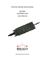
Remote Satellite Data Module RST600 Installation and User Manual Beam Communications Pty Ltd RST600 INSTALLATION & USER MANUAL RST600 Installation and User Manual Beam Communications Pty Ltd 8 Anzed Court, Mulgrave, Victoria, 3170, AUSTRALIA Information furnished by Beam Communications Pty Ltd (Beam) is believed to be accurate and reliable. However, no responsibility is assumed by Beam for its use, or for any infringement of patents or other rights of third parties, which may result from its use. No license is granted by implication or otherwise under any patent or patent rights of Beam. Beam reserves the right to change specifications at any time without notice. Copyright © 2008 Beam Communications Pty Ltd. All rights reserved Product name: RST600 Installation & User Manual Manual revision: 04 Part Number USRMAN000704 Issue Date: January 2008 2 RST600 INSTALLATION & USER MANUAL Contents CONTENTS..............................................................................................................................3 SAFETY INFORMATION.........................................................................................................4 ABOUT BEAM COMMUNICATIONS ............................................................................................5 CONVENTIONS IN THIS MANUAL ...............................................................................................6 WHAT IS THE RST600?..........................................................................................................7 PACKAGE CONTENTS ..............................................................................................................8 OPTIONAL BEAM ACCESSORIES...............................................................................................8 RST600 CONTENTS OVERVIEW ..............................................................................................9 INSTALLING THE RST600 ...................................................................................................10 CONNECTING THE ANTENNA CABLE ...............................................................................11 CONNECTING THE POWER CABLES.................................................................................12 SPECIFICATION SUMMARY ................................................................................................13 RS232 SPECIFICATION........................................................................................................13 PHYSICAL CONNECTION ........................................................................................................14 RS232 PORT SIGNAL SUPPORT AND HANDSHAKING ..............................................................14 RS232 PORT ELECTRICAL PARAMETERS ...............................................................................15 DATA CONNECTIVITY.............................................................................................................15 TROUBLESHOOTING THE RST600 ....................................................................................16 3 RST600 INSTALLATION & USER MANUAL Safety Information Note: Read the following information before installing and using the BEAM RST600. Your RST600 is a low power radio transmitter and receiver. When it is ON, it receives and sends out radio frequency (RF) signals. The design of your RST600 system complies with international safety standards. Refer to the appropriate section of the RST600 User Manual for additional relevant safety information. Warning: Do not open equipment. There are no user-serviceable parts inside. If a DC power supply is to be used, its output must comply with the Safety Extra Low Voltage (SELV) requirements of IEC60950. All connectors except the Line and Accessory sockets must only be connected to equipment ports which comply with the Safety Extra Low Voltage (SELV) requirements of IEC60950.” 4 RST600 INSTALLATION & USER MANUAL About BEAM Communications Beam Communications, is an authorised manufacturer of Iridium Satellite products. Beam develops subscriber products that utilise the Iridium satellite network of Low Earth Orbit satellites, known as LEOs. The Iridium network is extensively used around the world by commercial enterprises and defence agencies. Beam products address the needs of individuals, communities, government agencies and the corporate sector, providing voice and data access without the need for traditional wire-line or mobile phone infrastructure. As the Iridium satellite network is global, Beam’s products address global markets, across the spectrum of rural and remote users, including households, motor vehicles, telemetry, maritime and emergency services. Beam Communications Pty Ltd 8 Anzed Court, Mulgrave, Victoria, 3170, AUSTRALIA Web: www.beamcommunications.com Info: [email protected] Support: [email protected] Tel: +61 3 8851 0400 Fax: +61 3 9560 9055 5 RST600 INSTALLATION & USER MANUAL Conventions in this Manual Warnings, cautions and notes appear throughout this manual. They are represented by following conventions. Warning: This symbol and associated text indicate a warning note providing information to prevent personal injury or damage to equipment. Note: This symbol and associated text indicate a note providing general operating information. Interference: All wireless phones may get interference, which could affect performance. 6 RST600 INSTALLATION & USER MANUAL What is the RST600? The RST600 is a Remote Satellite Data Only Module designed to provide a reliable and cost effective data service connection when a wired connection is not available. It does this by providing a standard interface to the Iridium network — a satellitebased, wireless communications network that enables remote communication. The RST600 allows the connection of standard data terminals and other telecommunications devices. The RST600 from Beam Communications brings you all the convenience and ease of use of a Data Service anywhere in the world using the Iridium Satellite system. The data services available on the RST600 terminal include • Circuit Switched Data • Short Message Service (SMS) • Short Burst Data (SBD) 7 RST600 INSTALLATION & USER MANUAL Package Contents The RST600 package contains: 1 x RST600 Data & Power Interface cable assembly 1 x Iridium L-Band Transceiver 1 x RST997 DC – DC converter to supply 4.4VDC to the transceiver 1 x Cable Assembly for RST997 DC power supply 1 x User manual in hard copy 1 x Beam Starter CD including AT command set Optional Beam Accessories RST910 Fixed Mast Antenna RST915 Magnetic Mount Antenna RST920 Bolt Mount Antenna RST985 Serial to USB Converter Cable See your Service Provider for pricing and availability of these optional accessories Note: The RST requires an approved SIM to be inserted into the transceiver prior to operation. 8 RST600 INSTALLATION & USER MANUAL RST600 Contents Overview SIM card Housing Antenna Connector L-Band Transceiver Serial Data and Power Interface Connector RST997 Power Supply 10 – 32V DC to 4.4V DC Cable Assembly for DC power supply Data / Power Interface Cable Assembly consisting of 3 connectors Molex power connector to connect to DC power supply 9 pin serial connector for data 9 25 pin connector to carry power & data to L-Band Transceiver RST600 INSTALLATION & USER MANUAL Installing the RST600 Warning: Make sure the power is Not connected to the RST600 before you insert or remove the SIM card. If you do not, the memory on your SIM card may be damaged. Installing / Removing the SIM Card 1. Use an Alan key to remove both screws on the SIM card cover plate as shown. Keep the screws in a safe place whilst you install / remove the SIM card. 2. Slide the plastic SIM card holder sleeve rearward (opposite direction of the arrow) to release it from the locked position. 3. Insert the SIM card as shown, with the golden connectors facing inwards and the ‘cut corner’ of the SIM card facing uppermost. 4. Close the plastic sleeve down, and slide in the direction of the arrow until you feel it click into place. 5. Replace the cover, and fasten both screws. Scratching or bending the SIM card can easily damage the card or its metal contacts. So handle the SIM card with care. Avoid exposing the card to static electricity, water or dirt. 10 RST600 INSTALLATION & USER MANUAL Connecting the Antenna Cable 1. Ensure that the cable being used is long enough to reach from the RST600 to the Antenna location. 2. Plug the antenna cable into the antenna jack located on the top of the L-Band Transceiver 3. Ensure that you fasten the antenna cable securely to the TNC jack by screwing the cable firmly all the way in with your fingers. 4. It may be necessary to use an extension lead to get power to the unit or alternatively find a more appropriate location for the terminal and antenna to ensure minimum distance for the antenna cable 5. Please refer to the Iridium Antenna Guide for important information on installation and placement of your antenna. Note: Refer to the Antenna Installation Guide supplied with your RST600 for information on installing the antenna and assuring Quality of Service. This guide is also available for download at www.beamcommunications.com 11 RST600 INSTALLATION & USER MANUAL Connecting the Power Cables The terminal is powered by the supplied RST997 DC - DC converter that provides 4.4 Volt DC power to the Iridium transceiver unit. The DC – DC converter, accepts an 10 – 32V DC input. The DB9 Connector provides the Communications Serial port to the Iridium Transceiver terminal. This connects directly to a Computer or communicating terminal device. The Plastic Molex connects from the L-Band Transceiver directly to the power output from the DC – DC converter . The unit should be installed to ensure that the connectors remain accessible after installation for ease of service or disconnection when required. Note: Only the supplied RST997 DC-DC power converter should be used. Do not attempt to use any other power supply as this can cause damage to the unit which will void the warranty. 12 RST600 INSTALLATION & USER MANUAL Specification Summary RST600 Electrical Power 10 – 32 VDC Plug-pack (if provided) 90-250VAC 50/60Hz input Power Consumption (Average) Standby Mode 0.7W Talk/Transmit Mode 1.5W Modem Type Hayes Compatible Speed 2400 bps EMC Compliance C-Tick and A-Tick, CE mark Environmental Operating Temperature Range -20°C to +55°C ambient Operating Humidity Range <85% RH non-condensing Storage temperature -40C to +70C Weight 0.6 kg / 600 grams Dimensions 200x1100x40mm RF Interface (L-Band Transceiver) Frequency range Average Power 1616MHz to 1626.5MHz 7W during a transmit slot (max) Average Power Receiver Sensitivity Receiver Spurious Rejection offsets > 1 MHz (typical) 0.6 W during a frame (typical) -118.5 dBm at 50W (typical) at 60 dB Duplexing method TDD (Time Domain Duplex) Oscillator stability ±1.5ppm Input/output impedance 50 Ohms – TNC F Connector Multiplexing method: TDMA/FDMA 13 RST600 INSTALLATION & USER MANUAL RS232 Specification The RST600 is provided with an RS232 serial ports for data connection. The 9-pin Dtype (female) sockets, wired DCE for connection to a standard PC with a 1:1 cable. Physical Connection The pin-out of both connectors is described in the following table: Pin Signal Direction Description 1 DCD RST ¼ PC Data Carrier Detect 2 RXD RST ¼ PC Received Data 3 TXD PC ¼ RST Transmitted Data 4 DTR PC ¼ RST Date Terminal Ready 5 GND 6 DSR RST ¼ PC Data Set Ready (CTS and DCD) 7 RTS PC ¼ RST Request to Send 8 CTS PC ¼ RST Clear to Send 9 RI RST ¼ PC Ring Indicate Signal Ground (Common) RS232 Port Signal Support and Handshaking The Data port supports full software XON/XOFF handshaking on data (AT commands bypass this as usual for Hayes modems) or full hardware handshaking on RTS/CTS with DCD carrier indication. 14 RST600 INSTALLATION & USER MANUAL RS232 Port Electrical Parameters The LBT Data Port conforms to the RS232 interface specification with the following parameters: Parameter Specification Communication Rate 220 to 115,200 Baud Protocol 1 start bit, 8 data bits, no parity, 1 stop bit, asynchronous. Voltage Levels and Sensitivity RS232 compliant Data Connectivity To connect your RST600 to a PC or laptop, simply connect the 9-pin serial plug from your RST600 interface cable to a 9-pin (Male) port on your PC or laptop. If you do not have a serial port on your PC / laptop, an RST985 Serial to USB Converter Cable is available from your supplier. For information on how to setup a data call to / from your RST600 or information on sending SMS / SBD, please refer to the Beam Data Guide. For more information, please visit www.beamcommunications.com 15 RST600 INSTALLATION & USER MANUAL Troubleshooting the RST600 This chapter provides information to help you troubleshoot problems you may encounter while running the RST600. Q No power on RST600 A Check power is connected and AC available to the plug pack Q RST600 fails to register with the Iridium service after 30 seconds A Check power connection Check Antenna connection and location Ensure SIM is inserted Check correct power supply is being used Ensure that the SIM PIN (if required) has been entered Q PC cannot connect to RST600 A Check that the correct cable is used on the correct port, and that the bit rate is set the same for both PC and RST600 Q Your PIN2 is locked. A Enter the PIN2 unblocking key (PUK2) or contact our service provider. Q Your SIM card won’t work . A Is the card inserted the correct way? Is the SIM gold chip visibly damaged or scratched? Return the card to your service provider. Check the SIM and phone contacts. If they are dirty, clean them with an antistatic cloth. 16 RST600 INSTALLATION & USER MANUAL Q A You can’t make calls. Check that the antenna is properly mounted. Do you have a clear view of the sky? Did you enter the number in international format? All calls made from the Iridium System require a special calling sequence; please refer to your Service Provider for these details. Check the signal strength meter. If the signal is weak, move the antenna to a more open area. Check the Network Selection settings. Check your Operator coverage map. Is R e s t r i c t e d displayed? Check the Call Barring setting. Has a new SIM card been inserted? Q A You can’t receive calls Check to see that your phone is powered on. Check the antenna. Is it properly mounted? Do you have a clear view of the sky? Check the signal strength. If the signal is weak, move the antenna to a more open area. Check the Call Forwarding and Call Barring settings. Q You can’t make international calls. A Have you included the relevant codes? Press and hold the (+) key to display the international dialling prefix (+), and then enter the appropriate country code, followed by the phone number. Q Your PIN is blocked A Enter the PIN unblocking key (PUK1) or contact your service provider Q You can’t cancel call forwarding or call barring A Wait until you are in an area with good network coverage and try again. Q Your PIN is blocked A Check Card or Insert Card. Check the card is inserted correctly Check the contacts of the card are clean Clean the chip with a soft cloth See your Service Provider if continues 17 RST600 INSTALLATION & USER MANUAL Beam Warranty Conditions Beam Communications gives this express warranty (along with extended warranty endorsements, where applicable) in lieu of all other warranties, express or implied, including (without limitation), warranties of merchantability and fitness for a particular purpose. This constitutes our sole warranty and obligation with regard to our products as well as the Customer’s sole remedy. Beam Communications expressly disclaims all liability and responsibility for any special, indirect or consequential damages or any further loss of any kind whatsoever resulting from the use of our product(s). The Customer’s sole and exclusive remedy and the limit of Beam’s liability for any loss whatsoever, shall not exceed the purchase price paid by the Customer for the product to which a claim is made. 1. 2. 3. 4. 5. 6. 7. 8. 9. All products manufactured by Beam Communications are warranted to be free from defects in material and workmanship in accordance with and subject to the following terms and conditions: This warranty is limited to the original Customer only. It cannot be transferred or assigned to third parties unless the intent to transfer to a third party is expressly indicated in a purchase order and/or warranty-processing arrangements have been agreed upon in writing by Beam. Beam Communications does not warrant any installation, maintenance or service of the Products not performed by Beam, nor does it warrant the use of Products with unapproved ancillary products. Beam Communications will correct any defects in material or workmanship of products manufactured by Beam which appear within (12) months, from the date of shipment by Beam Communications to the Customer. Beam Communications will repair or replace, at our option, any defective product, provided that our analysis and/or inspection discloses that such defects developed under normal and proper use. This warranty does not extend to goods subjected to liquid or particulate ingress, extreme humidity, misuse, neglect, accident or improper installation, or to maintenance or repair of products that have been altered or repaired by anyone except Beam Communications unless otherwise stated in writing. The warranty is a return-to-base warranty and freight is paid by the sender. A charge of USD150 including return freight will be made for testing returned product which is not defective or is found to be defective as the result of improper use, maintenance or neglect. Beam Communications will not accept responsibility for any invoiced goods or services that are not covered by a Beam Communications written purchase order. Under no circumstances does Beam Communications agree to pay for labour or other related expenses associated with the troubleshooting and/or repair of our product without prior specific written authorization. Information in our descriptive literature is based on product specifications that are current at the time of publication. Product specifications, designs and descriptive literature are subject to change as improvements are introduced. Although we announce changes as they occur, we cannot guarantee notification to every Customer. Beam Communications warrants delivered product to conform to the most current specifications, designs and descriptive literature. This warranty policy may be expanded or limited, for particular categories of products or Customers, by information sheets published as deemed appropriate by Beam Communications. In particular, the warranty for third party Products is that of the third party and not Beams warranty. 18