1
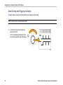
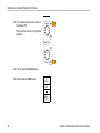
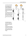
Tektronix 4000 Series Oscilloscope
Demo Instruction Manual
www.tektronix.com
071-2138-01
Copyright © Tektronix. All rights reserved. Licensed software products are owned by Tektronix or its subsidiaries or suppliers, and are protected by
national copyright laws and international treaty provisions.
Tektronix products are covered by U.S. and foreign patents, issued and pending. Information in this publication supersedes that in all previously
published material. Specifications and price change privileges reserved.
TEKTRONIX and TEK are registered trademarks of Tektronix, Inc.
Wave Inspector is a trademark of Tektronix, Inc.
For safety information on the DPO4000 and MSO4000 Oscilloscopes, refer to the Tektronix 4000 Series Digital Phosphor Oscilloscope User Manual.
Contacting Tektronix
Tektronix, Inc.
14200 SW Karl Braun Drive
P.O. Box 500
Beaverton, OR 97077
USA
For product information, sales, service, and technical support:
In North America, call 1-800-833-9200.
Worldwide, visit www.tektronix.com to find contacts in your area.
Table of Contents
Table of Contents
Getting Started with the Tektronix 4000 Series . . . . . . . . . . . . . . . . . . . . . . . . . . . . . . . . . . . . . . . . . . . . . . . . . . . . . . . . . . . . . . . . . . . . . . . . . . . . . . . . . . . . . . . . . . . .
Demo I: Acquiring a Signal. . . . . . . . . . . . . . . . . . . . . . . . . . . . . . . . . . . . . . . . . . . . . . . . . . . . . . . . . . . . . . . . . . . . . . . . . . . . . . . . . . . . . . . . . . . . . . . . . . . . . .
Demo II: Using Vertical Controls . . . . . . . . . . . . . . . . . . . . . . . . . . . . . . . . . . . . . . . . . . . . . . . . . . . . . . . . . . . . . . . . . . . . . . . . . . . . . . . . . . . . . . . . . . . . . . . .
Demo III: Using Horizontal Controls . . . . . . . . . . . . . . . . . . . . . . . . . . . . . . . . . . . . . . . . . . . . . . . . . . . . . . . . . . . . . . . . . . . . . . . . . . . . . . . . . . . . . . . . . . . .
Demo IV: Using Run/Stop Controls. . . . . . . . . . . . . . . . . . . . . . . . . . . . . . . . . . . . . . . . . . . . . . . . . . . . . . . . . . . . . . . . . . . . . . . . . . . . . . . . . . . . . . . . . . . . .
Demo V: Using Trigger Controls . . . . . . . . . . . . . . . . . . . . . . . . . . . . . . . . . . . . . . . . . . . . . . . . . . . . . . . . . . . . . . . . . . . . . . . . . . . . . . . . . . . . . . . . . . . . . . . .
Demo VI: Using Cursors . . . . . . . . . . . . . . . . . . . . . . . . . . . . . . . . . . . . . . . . . . . . . . . . . . . . . . . . . . . . . . . . . . . . . . . . . . . . . . . . . . . . . . . . . . . . . . . . . . . . . . .
Demo VII: Taking Measurements . . . . . . . . . . . . . . . . . . . . . . . . . . . . . . . . . . . . . . . . . . . . . . . . . . . . . . . . . . . . . . . . . . . . . . . . . . . . . . . . . . . . . . . . . . . . . .
Demo VIII: Saving a Screen Image. . . . . . . . . . . . . . . . . . . . . . . . . . . . . . . . . . . . . . . . . . . . . . . . . . . . . . . . . . . . . . . . . . . . . . . . . . . . . . . . . . . . . . . . . . . .
1
2
5
7
8
8
11
13
16
Giving Demos of Advanced Tektronix 4000 Features . . . . . . . . . . . . . . . . . . . . . . . . . . . . . . . . . . . . . . . . . . . . . . . . . . . . . . . . . . . . . . . . . . . . . . . . . . . . . . . . . . . .
Overall Package. . . . . . . . . . . . . . . . . . . . . . . . . . . . . . . . . . . . . . . . . . . . . . . . . . . . . . . . . . . . . . . . . . . . . . . . . . . . . . . . . . . . . . . . . . . . . . . . . . . . . . . . . . . . . . . .
Performance. . . . . . . . . . . . . . . . . . . . . . . . . . . . . . . . . . . . . . . . . . . . . . . . . . . . . . . . . . . . . . . . . . . . . . . . . . . . . . . . . . . . . . . . . . . . . . . . . . . . . . . . . . . . . . . . . . . .
Wave Inspector Demos . . . . . . . . . . . . . . . . . . . . . . . . . . . . . . . . . . . . . . . . . . . . . . . . . . . . . . . . . . . . . . . . . . . . . . . . . . . . . . . . . . . . . . . . . . . . . . . . . . . . . . . .
Demo IX: Setting Up I2C Signals . . . . . . . . . . . . . . . . . . . . . . . . . . . . . . . . . . . . . . . . . . . . . . . . . . . . . . . . . . . . . . . . . . . . . . . . . . . . . . . . . . . . . . . . . . . . . .
Demo X: Using the Wave Inspector’s Zoom and Pan Functionality . . . . . . . . . . . . . . . . . . . . . . . . . . . . . . . . . . . . . . . . . . . . . . . . . . . . . . . . . .
Demo XI: Using the Wave Inspector’s Search Functionality . . . . . . . . . . . . . . . . . . . . . . . . . . . . . . . . . . . . . . . . . . . . . . . . . . . . . . . . . . . . . . . . . .
Demo XII: Using Serial Triggering and Analysis . . . . . . . . . . . . . . . . . . . . . . . . . . . . . . . . . . . . . . . . . . . . . . . . . . . . . . . . . . . . . . . . . . . . . . . . . . . . . .
Demo XIII: Searching Serial Signals. . . . . . . . . . . . . . . . . . . . . . . . . . . . . . . . . . . . . . . . . . . . . . . . . . . . . . . . . . . . . . . . . . . . . . . . . . . . . . . . . . . . . . . . . . .
Demo XIV: Monitoring and Decoding RS-232 Signals . . . . . . . . . . . . . . . . . . . . . . . . . . . . . . . . . . . . . . . . . . . . . . . . . . . . . . . . . . . . . . . . . . . . . . . .
Demo XV: Triggering on a Serial Data Pattern (e.g. RS-232) . . . . . . . . . . . . . . . . . . . . . . . . . . . . . . . . . . . . . . . . . . . . . . . . . . . . . . . . . . . . . . . .
20
20
21
22
23
29
35
40
51
55
63
Tektronix 4000 Oscilloscope Demo Instruction Manual
i
Table of Contents
ii
Giving Demos of MSO4000 Features. . . . . . . . . . . . . . . . . . . . . . . . . . . . . . . . . . . . . . . . . . . . . . . . . . . . . . . . . . . . . . . . . . . . . . . . . . . . . . . . . . . . . . . . . . . . . . . . . . . . .
Ease of Use . . . . . . . . . . . . . . . . . . . . . . . . . . . . . . . . . . . . . . . . . . . . . . . . . . . . . . . . . . . . . . . . . . . . . . . . . . . . . . . . . . . . . . . . . . . . . . . . . . . . . . . . . . . . . . . . . . . .
Performance. . . . . . . . . . . . . . . . . . . . . . . . . . . . . . . . . . . . . . . . . . . . . . . . . . . . . . . . . . . . . . . . . . . . . . . . . . . . . . . . . . . . . . . . . . . . . . . . . . . . . . . . . . . . . . . . . . . .
MSO4000 Demos . . . . . . . . . . . . . . . . . . . . . . . . . . . . . . . . . . . . . . . . . . . . . . . . . . . . . . . . . . . . . . . . . . . . . . . . . . . . . . . . . . . . . . . . . . . . . . . . . . . . . . . . . . . . . .
Demo XVI: Setting up Digital Channels . . . . . . . . . . . . . . . . . . . . . . . . . . . . . . . . . . . . . . . . . . . . . . . . . . . . . . . . . . . . . . . . . . . . . . . . . . . . . . . . . . . . . . .
Demo XVII: Discovering Per-channel Thresholds. . . . . . . . . . . . . . . . . . . . . . . . . . . . . . . . . . . . . . . . . . . . . . . . . . . . . . . . . . . . . . . . . . . . . . . . . . . . .
Demo XVIII: Labeling Channels . . . . . . . . . . . . . . . . . . . . . . . . . . . . . . . . . . . . . . . . . . . . . . . . . . . . . . . . . . . . . . . . . . . . . . . . . . . . . . . . . . . . . . . . . . . . . . .
Demo XIX: Exploring Parallel Buses . . . . . . . . . . . . . . . . . . . . . . . . . . . . . . . . . . . . . . . . . . . . . . . . . . . . . . . . . . . . . . . . . . . . . . . . . . . . . . . . . . . . . . . . . .
Demo XX: Triggering on Parallel Bus Data Values. . . . . . . . . . . . . . . . . . . . . . . . . . . . . . . . . . . . . . . . . . . . . . . . . . . . . . . . . . . . . . . . . . . . . . . . . . . .
Demo XXI: Searching for Parallel Bus Data Values. . . . . . . . . . . . . . . . . . . . . . . . . . . . . . . . . . . . . . . . . . . . . . . . . . . . . . . . . . . . . . . . . . . . . . . . . . .
Demo XXII: Discovering Multi-channel Setup and Hold. . . . . . . . . . . . . . . . . . . . . . . . . . . . . . . . . . . . . . . . . . . . . . . . . . . . . . . . . . . . . . . . . . . . . . .
Demo XXIII: Zooming in on White Edges . . . . . . . . . . . . . . . . . . . . . . . . . . . . . . . . . . . . . . . . . . . . . . . . . . . . . . . . . . . . . . . . . . . . . . . . . . . . . . . . . . . . .
66
66
66
68
69
76
77
79
84
87
89
96
Operating the Demo Board. . . . . . . . . . . . . . . . . . . . . . . . . . . . . . . . . . . . . . . . . . . . . . . . . . . . . . . . . . . . . . . . . . . . . . . . . . . . . . . . . . . . . . . . . . . . . . . . . . . . . . . . . . . . . . .
Operating the Board. . . . . . . . . . . . . . . . . . . . . . . . . . . . . . . . . . . . . . . . . . . . . . . . . . . . . . . . . . . . . . . . . . . . . . . . . . . . . . . . . . . . . . . . . . . . . . . . . . . . . . . . . . .
102
103
Troubleshooting the Demo Board . . . . . . . . . . . . . . . . . . . . . . . . . . . . . . . . . . . . . . . . . . . . . . . . . . . . . . . . . . . . . . . . . . . . . . . . . . . . . . . . . . . . . . . . . . . . . . . . . . . . . . . .
104
Tektronix 4000 Oscilloscope Demo Instruction Manual
Getting Started with the Tektronix 4000 Series
Getting Started with the Tektronix 4000 Series
The following instructions will quickly guide you through basic controls and capabilities of the DPO4000 and MSO4000 Series
oscilloscopes. Learn about more advanced capabilities by reading the Tektronix 4000 Series User Manual (071-2121-XX).
NOTE. This manual works with DPO4000 and MSO4000 Series oscilloscopes with firmware version 2.XX. If your oscilloscope
uses firmware version 1.XX, download new firmware and update your oscilloscope using procedures described in your oscilloscope
user manual.
NOTE. This manual is part of the Tektronix 020-2694-XX demo kit. The kit includes a demo board, this manual, and a USB cable.
Tektronix 4000 Oscilloscope Demo Instruction Manual
1
Getting Started with the Tektronix 4000 Series
Demo I: Acquiring a Signal
1. Connect the host side of the USB cable to
the USB port on the lower-left corner of the
oscilloscope front panel — or to either of
the two USB host ports on the rear panel.
2. Connect the other end of the cable to
the device port on the demo board. (See
page 102, Operating the Demo Board.)
3. Confirm that the LED labeled USB POWER
is lit on the demo board.
2
Tektronix 4000 Oscilloscope Demo Instruction Manual
Getting Started with the Tektronix 4000 Series
4. Connect a P6139A probe to channel 1.
Then connect the ground lead of the
P6139A probe to a point labeled GND on
the demo board. Attach the probe tip to
the square pin on the demo board labeled
CNT CLK.
NOTE. CNT CLK is a clock used for a
synchronous counter.
5. Push Default Setup to put the oscilloscope
back to a known starting point. In general,
this is a good thing to do any time you are
starting a new task.
Tektronix 4000 Oscilloscope Demo Instruction Manual
3
Getting Started with the Tektronix 4000 Series
6. Push Autoset.
Autoset automatically adjusts the
horizontal, vertical, and trigger parameters
to give a usable display of the signal of
interest. You should now see several
cycles of the clock signal.
4
Tektronix 4000 Oscilloscope Demo Instruction Manual
Getting Started with the Tektronix 4000 Series
Demo II: Using Vertical Controls
1. Turn the front-panel channel 1 Vertical
Scale knob in both directions and observe
how the display changes. Also, notice the
channel 1 readout on the lower left of the
display shows the current volts/div setting.
Set the Vertical Scale to 1 V/div.
2. Turn the front-panel channel 1 Vertical
Position knob in both directions and
observe how the display changes. Position
the waveform in the center of the display.
Tektronix 4000 Oscilloscope Demo Instruction Manual
5
Getting Started with the Tektronix 4000 Series
3. Push the front-panel channel 2 button to
turn on channel 2. Push it again to turn off
channel 2.
6
Tektronix 4000 Oscilloscope Demo Instruction Manual
Getting Started with the Tektronix 4000 Series
Demo III: Using Horizontal Controls
1. Turn the front-panel Horizontal Scale
knob in both directions and observe the
display. Also, notice the horizontal readout
indicating the current time/div setting. Set
the Horizontal Scale to 20 ns/div.
2. Turn the front-panel Horizontal Position
knob both directions and observe the
display. Notice that this affects the trigger
position icon (the big T on an orange
background). Return the trigger position
icon to center screen.
3. Take a look at the graphic shown above
the graticule. The long yellow bar
represents the overall acquisition while
the gray brackets indicate the portion of
the acquisition you are looking at on the
screen.
Tektronix 4000 Oscilloscope Demo Instruction Manual
7
Getting Started with the Tektronix 4000 Series
Demo IV: Using Run/Stop Controls
1. Push the Run/Stop button. This stops
acquisitions with the last acquired
waveform on the display.
2. Push Single to have the oscilloscope
acquire a single waveform and then stop.
3. Push the Run/Stop button again to restart
acquisitions.
Demo V: Using Trigger Controls
1. Turn the Trigger Level knob in both
directions and observe the display. Turn it
far enough to move the trigger level off the
waveform.
8
Tektronix 4000 Oscilloscope Demo Instruction Manual
Getting Started with the Tektronix 4000 Series
Notice that the oscilloscope loses its stable
trigger and the waveform now appears to
randomly scroll by.
2. Push the Force Trig button once and
notice that the oscilloscope shows a single
acquisition for a moment. This gives you
an idea of what the waveform looks like
so you can set an appropriate and stable
trigger.
Tektronix 4000 Oscilloscope Demo Instruction Manual
9
Getting Started with the Tektronix 4000 Series
3. Push the Set to 50% button. This
automatically sets the trigger level to the
midpoint of the signal for a stable trigger.
10
Tektronix 4000 Oscilloscope Demo Instruction Manual
Getting Started with the Tektronix 4000 Series
Demo VI: Using Cursors
1. Push the front-panel Cursors button.
Two vertical bar cursors now appear in
the graphic above the graticule. The
corresponding cursor readout displays
the time of each cursor relative to the
trigger and amplitude along with the deltas
between the cursors.
2. Using the multipurpose a and b knobs,
bring the cursors on screen.
Tektronix 4000 Oscilloscope Demo Instruction Manual
11
Getting Started with the Tektronix 4000 Series
Hint: To move the cursors faster, turn off
fine mode by pushing the Fine button,
if lit, on the front panel between the two
multipurpose knobs.
3. Place one cursor at the midpoint of the
first falling edge. Place the other cursor at
the midpoint of the second falling edge to
measure the signal’s period. The cursor
readout should show a difference between
the cursors of approximately 100 ns.
Hint: To move the cursors more slowly, turn
the fine mode back on by pushing the Fine
button, if unlit, on the front panel between
the two multipurpose knobs.
12
Tektronix 4000 Oscilloscope Demo Instruction Manual
Getting Started with the Tektronix 4000 Series
4. Push Cursors two more times to turn them
off.
Demo VII: Taking Measurements
1. Push the front-panel Measure button.
Tektronix 4000 Oscilloscope Demo Instruction Manual
13
Getting Started with the Tektronix 4000 Series
2. Push the lower-bezel Select Measurement
button.
Select
Measurement
Remove
Measurement
Gating
Screen
Statistics
On
Reference
Levels
Indicators
Configure
Cursors
Period
Freq
Value
99.96ns
10.0M
Mean
99.99n
10.00M
Min
99.85n
9.987M
Max
100.1n
10.01M
Std Dev
62.89p
6.754k
3. Push the side-bezel Period button.
Period
4. Push the side-bezel Frequency button.
Frequency
5. Observe the measurement readout.
The readout indicates the frequency and period
as well as the mean, minimum, maximum, and
standard deviation of the measurements.
14
Tektronix 4000 Oscilloscope Demo Instruction Manual
Getting Started with the Tektronix 4000 Series
6. Push the lower-bezel Remove Measurement
button.
7. Push the side-bezel Remove All
Measuremnts button.
Remove All
Measuremnts
8. Push Menu Off to the lower-right of the display
to remove the side menu. Push it again to
remove the lower-bezel menu.
Tektronix 4000 Oscilloscope Demo Instruction Manual
15
Getting Started with the Tektronix 4000 Series
Demo VIII: Saving a Screen Image
1. Insert either a USB flash drive or a
CompactFlash card.
There is one USB 2.0 Host port on the front and
two more ports on the rear of the oscilloscope.
2. Push the front-panel Save/Recall Menu button.
16
Tektronix 4000 Oscilloscope Demo Instruction Manual
Getting Started with the Tektronix 4000 Series
3. Push the lower-bezel Save Screen Image
button.
4. If needed, use multipurpose knob a to select
the drive that you are using.
Tektronix 4000 Oscilloscope Demo Instruction Manual
17
Getting Started with the Tektronix 4000 Series
5. Push the front-panel Select button.
This lets you expand or contract your view into
the contents of the drive that you are using.
Expanded list
6. Select the desired file format with the
side-bezel button.
7. Push OK Save Screen Image.
Contracted list
File Format
.png
OK
Save
Screen
Image
8. To easily save multiple images, push the
front-panel Save button.
By default, the lower-bezel Assign Save to
button is set to Image.
18
Tektronix 4000 Oscilloscope Demo Instruction Manual
Getting Started with the Tektronix 4000 Series
Now, whenever you push the front-panel Save
button, a screen image with an automatically
incremented filename is saved to the storage
location you specified.
To change what is saved each time you
push the front-panel Save button, push the
lower-bezel Assign Save to button and then
push one of the side-bezel buttons: Screen
Image, Waveform, or Setup.
Tektronix 4000 Oscilloscope Demo Instruction Manual
Assign
Save to
Image
19
Giving Demos of Advanced Tektronix 4000 Features
Giving Demos of Advanced Tektronix 4000 Features
This section demonstrates a few features that set the Tektronix 4000 Series Oscilloscope apart from any other oscilloscope
on the market.
Overall Package
Large 10.4 Inch XGA Display: Oscilloscopes are visual tools and, as such, work well with large, bright displays.
Knob-per-Channel Vertical Controls: Many oscilloscopes multiplex the vertical controls so you have to select a
channel before changing its vertical scale or position. A separate adjustment knob for each channel makes the oscilloscope
more efficient and intuitive.
Front-panel USB and CompactFlash Ports: These ports make it easy to transfer screen images, oscilloscope setups, and
waveform data from the oscilloscope to your workstation.
Only 5.4 Inches Deep: The Tektronix 4000 Series uses a small amount of bench space, especially given its performance
level, allowing customers to set their device under test in front of the oscilloscope.
Portable: Only 11 pounds and a sturdy handle make the Tektronix 4000 Series easily portable.
Localization: The user interface of the Tektronix 4000 Series oscilloscope is available in these 11 languages: English, French,
German, Italian, Spanish, Portuguese (Brazilian), Russian, Japanese, Korean, Simplified Chinese, and Traditional Chinese.
20
Tektronix 4000 Oscilloscope Demo Instruction Manual
Giving Demos of Advanced Tektronix 4000 Features
Performance
Product
DPO4104 &
MSO4104
DPO4054 &
MSO4054
DPO4034 &
MSO4034
DPO4032 &
MSO4032
Bandwidth
1 GHz
500 MHz
350 MHz
350 MHz
DPO4000 Channels
4
4
4
2
MSO4000 Channels
4 + 16
4 + 16
4 + 16
2 + 16
Max Analog Sample Rate (all channels)
5 GS/s
2.5 GS/s
2.5 GS/s
2.5 GS/s
Main Record Length (all channels)
10 M
10 M
10 M
10 M
MSO4000 MagniVu Record Length (all digital
channels)
10 K
10 K
10 K
10 K
5X Oversampling on All Channels. All Tektronix 4000 Series oscilloscopes offer ≥ 5x over-sampling on all channels with
sin(x)/x interpolation standard. This ensures full-single shot bandwidth on all channels. Oscilloscopes with lower sample rates
and/or linear interpolation often can only offer full single-shot bandwidth on fewer channels.
10 M Record Lengths on All Channels. All Tektronix 4000 Series oscilloscopes offer standard 10 M record lengths on all
channels. Not only is this more than any other midrange oscilloscope’s standard offerings, it is also more than many offer even
with very expensive options.
Waveform Labels. The Tektronix 4000 Series oscilloscopes support adding labels to signals on the display. This is increasing
useful as the number of signals on the display increases.
Tektronix 4000 Oscilloscope Demo Instruction Manual
21
Giving Demos of Advanced Tektronix 4000 Features
Wave Inspector Demos
Background.
Digital oscilloscope record lengths have gone from 500 points in the early 1980’s to millions of points today.
The Tektronix 4000 series places emphasis not only on the quantity of record length provided but also on the usability of the
data. Imagine trying to find what you are looking for on the Web these days without search engines like Google.
As record lengths have gotten longer, virtually every digital oscilloscope has implemented a zoom model. However, most
zoom models are operated with controls buried in menus or front-panel controls that are multiplexed with other functions. The
Tektronix 4000 series zoom controls are easily accessible on the front panel.
22
Tektronix 4000 Oscilloscope Demo Instruction Manual
Giving Demos of Advanced Tektronix 4000 Features
The following are general demo procedures that cover the key points of Wave Inspector and Serial Triggering and Analysis.
Demo IX: Setting Up I2C Signals
1. Connect the ground lead of a P6139A
probe to a point labeled GND on the demo
board.
Connect the P6139A probe from channel 1
on the oscilloscope to the SCLK test point
on the demo board.
2. Connect the ground lead of a second
P6139A probe to a point labeled GND on
the demo board.
Connect the second P6139A probe from
channel 2 on the oscilloscope to the I2C
SDA test point on the demo board.
Tektronix 4000 Oscilloscope Demo Instruction Manual
23
Giving Demos of Advanced Tektronix 4000 Features
3. Check that the I2C LED on the demo board
is lit. If it is not, push the SERIAL SELECT
button on the demo board as many times
as needed to light the I2C LED.
4. Push the front-panel Default Setup button.
5. Turn the front-panel Trigger Level knob to
set the trigger level to approximately 2 V.
24
Tektronix 4000 Oscilloscope Demo Instruction Manual
Giving Demos of Advanced Tektronix 4000 Features
6. Push the front-panel channel 2 button to
turn on channel 2.
7. Turn the front-panel channel 1 and
channel 2 Vertical Scale knobs so that
both channel 1 and channel 2 are set to
2.0 V/div.
Tektronix 4000 Oscilloscope Demo Instruction Manual
25
Giving Demos of Advanced Tektronix 4000 Features
8. Turn the channel 1 and channel 2 Vertical
Position knobs to position channel 1 near
the top of the graticule and channel 2 near
the middle.
9. Push the front-panel Acquire button to
display the acquire menu.
10. Push the lower-bezel Record Length
button (if not already active), and the
side-bezel 1M points button.
26
Tektronix 4000 Oscilloscope Demo Instruction Manual
Giving Demos of Advanced Tektronix 4000 Features
11. Turn the front-panel Horizontal Scale knob
to set the horizontal scale to 20.0 ms/div.
Hint: If you want to save this setup so that
you can recall it at the beginning of each
demo, push the front-panel Save/Recall
Menu button, the lower-bezel Save Setup
button, and select where you want to store
the setup.
12. Push the front-panel Single button to
acquire a single acquisition.
Tektronix 4000 Oscilloscope Demo Instruction Manual
27
Giving Demos of Advanced Tektronix 4000 Features
You are now looking at the clock (yellow
ch1) and data (blue ch2) lines of an I2C
bus.
Hint: If the waveforms do not look like the
display to the right, go back to step 1 and
confirm that you connected both probes to
the correct pins on the demo board.
28
Tektronix 4000 Oscilloscope Demo Instruction Manual
Giving Demos of Advanced Tektronix 4000 Features
Demo X: Using the Wave Inspector’s Zoom and Pan Functionality
This section shows how to use the Wave Inspector’s Zoom-Pan knob to demo zoom and pan functionality.
1. Notice the Wave Inspector portion of
the front panel. This set of dedicated
controls makes navigating and analyzing
waveforms easier.
Tektronix 4000 Oscilloscope Demo Instruction Manual
29
Giving Demos of Advanced Tektronix 4000 Features
The pan-zoom control consists of the following:
2. An outer pan knob.
3. An inner zoom knob.
4. Turn the zoom (inner) knob a few clicks
clockwise. The zoom feature should turn
on. You are seeing:
The entire acquisition in the top
window.
What you are zooming in on within the
gray top window brackets.
The zoomed view in the bottom
window.
30
Tektronix 4000 Oscilloscope Demo Instruction Manual
Giving Demos of Advanced Tektronix 4000 Features
5. Zoom in and out to illustrate how the center knob works. End in a spot where you are zoomed in on a single burst of clocks.
Notice that you do not have to turn a horizontal position control many times to move the zoom window to the beginning of the
acquisition, nor do you have to zoom way back out so you could move the window quickly, and then zoom back in when you
arrived at the new location. This is where the Tektronix 4000 Series pan function helps.
6. Turn the pan (outer) knob counterclockwise
a bit. Notice the extremely intuitive nature
of the zoom/pan controls.
Counterclockwise turning moves the
zoom box left.
Clockwise turning moves the zoom box
right.
The further you turn the pan knob, the
faster the zoom box moves.
You can move from one end of the
acquisition to the other end in a couple
of seconds even with a 10 M record
length!
Tektronix 4000 Oscilloscope Demo Instruction Manual
31
Giving Demos of Advanced Tektronix 4000 Features
7. If you do not want to hold the pan knob
while looking through the waveform,
use the play/pause feature. Pressing
the play/pause button will cause the
oscilloscope to scroll the waveform
automatically for you.
To show this, push the play/pause button.
The waveform should start scrolling.
Play speed is adjusted by turning the
pan knob.
To pan in the other direction, just turn
the pan knob the other way to slow the
zoom box down and have it change
direction.
To quickly jump to another portion of
the record and resume playing when
done, turn the pan knob all the way in
that direction. This is pan on top of
play/pause.
Push the play/pause button again
to stop when there is something
(anything) of interest on the screen.
32
Tektronix 4000 Oscilloscope Demo Instruction Manual
Giving Demos of Advanced Tektronix 4000 Features
8. When you have found something in the
waveform that you are interested in, mark
it for further reference.
To do this, push the Set/Clear button on
the front panel to place a mark.
Notice the solid white triangle that
appears on the display. Later, you will
see why the triangles are solid.
This triangle is like a bookmark on the
waveform.
Tektronix 4000 Oscilloscope Demo Instruction Manual
33
Giving Demos of Advanced Tektronix 4000 Features
9. Use the pan (outer) knob to quickly move
to a few other interesting points in the
waveform and place marks on them.
10. Use the front-panel ← (previous) and
→ (next) arrow buttons (arrows around
Set/Clear) to navigate back and forth
between marks instantly.
34
Tektronix 4000 Oscilloscope Demo Instruction Manual
Giving Demos of Advanced Tektronix 4000 Features
11. Push the Set/Clear button to remove a
mark from the waveform.
The zoom, pan, play/pause,
setting/clearing/navigating of marks
are all very useful features for manually
navigating and inspecting the waveform.
NOTE. To remove a mark with Set/Clear, first
center the zoom box on the mark, either with
the → and ← arrow buttons, or panning on
the mark.
Demo XI: Using the Wave Inspector’s Search Functionality
This section shows how to use the powerful search engine to find events for you.
1. Push the front-panel Search button.
Tektronix 4000 Oscilloscope Demo Instruction Manual
35
Giving Demos of Advanced Tektronix 4000 Features
2. Push the lower-bezel Search button.
Search
Off
Search
Type
Pulse
Width
Source
Polarity
Positive
Set mark
When
< 5.00 us
Threshold
2.00 V
NOTE. If the button in step 3 below is labeled
Search Marks on your DPO4000 oscilloscope
instead of Search then you may be using earlier
version 1.XX firmware on your oscilloscope.
For best results with these demos, update your
oscilloscope firmware. To do this, follow the
procedure given in your oscilloscope user manual.
3. Push the side-bezel Search button to select
On.
4. Push the side-bezel Clear All Marks button.
Search
On| Off
Clear All
Marks
You are removing the marks that you manually
placed on the waveform.
36
Tektronix 4000 Oscilloscope Demo Instruction Manual
Giving Demos of Advanced Tektronix 4000 Features
5. Push the lower-bezel Search Type button
and turn multipurpose knob a to select Pulse
Width from a list of choices.
Search
Type
Pulse
Width
Review all the search choices available and
the flexible capability of the Tektronix 4000
Series oscilloscopes.
6. Push the lower-bezel Source button and turn
multipurpose knob a to select 2 from the list of
channels on the screen.
7. Confirm the polarity is positive.
The lower-bezel Polarity button should
include the word Positive below it. If not, push
Polarity and then the side-bezel Positive
button.
8. Push the bottom-bezel Threshold button.
Then turn multipurpose knob a to set the
threshold to approximately the midpoint of the
channel 2 waveform (e.g. 2.00 V).
Tektronix 4000 Oscilloscope Demo Instruction Manual
37
Giving Demos of Advanced Tektronix 4000 Features
9. Push the lower-bezel Set Mark When button.
If it is not already selected, push the side-bezel
Pulse Width < 8.00 ns button.
Set Mark
When
< 8.00 ns
10. Using the multipurpose knob a, dial up the
pulse width to somewhere around 5 μs. This is
where you should begin seeing marks.
Hint: To get to 5 μs faster, first push the
front-panel Fine button, if lit, to turn off the
Fine function.
Notice both the hollow white triangles placed in
the graticule and the number of search events
found, shown in the lower left corner of the
display. Hollow triangles show search results
and solid triangles show user placed marks.
Dial up the pulse width to 11 μs to show that
as you adjust the search criteria, the search
results update. Then dial it back down to 5 μs.
11. Jump from mark to mark using the front-panel
← (previous) and → (next) arrow buttons.
38
Tektronix 4000 Oscilloscope Demo Instruction Manual
Giving Demos of Advanced Tektronix 4000 Features
12. Turn the zoom (inner) knob, if needed, to
zoom in to give you a good view of each pulse
that met the criteria. For example, try a zoom
factor of 5kX.
NOTE. The oscilloscope displays the zoom value
near the upper-left corner of the display.
13. When you finish this demo, turn off Search by
pushing the lower-bezel Search button.
If needed, then push the side-bezel Search
button so it highlights Off.
Search
On
Search
On |Off
14. Push Menu Off to the right of the display
to remove the side menu. Push it again to
remove the lower-bezel menu.
Tektronix 4000 Oscilloscope Demo Instruction Manual
39
Giving Demos of Advanced Tektronix 4000 Features
Demo XII: Using Serial Triggering and Analysis
This demo shows a much easier and more efficient way to analyze your serial buses.
NOTE. Start from where you finished the last demo.
1. Turn the zoom (inner) knob to adjust your
zoom factor to 50 X.
Hint: The oscilloscope will display the zoom
value near the upper-left corner of the display.
40
Tektronix 4000 Oscilloscope Demo Instruction Manual
Giving Demos of Advanced Tektronix 4000 Features
2. Pan the zoom window, if needed, so that the
screen looks like the one shown to the right.
Notice how easy it is to set up a bus on the
Tektronix 4000 Series while you do steps 3
through 9.
3. Push the B1 button.
Tektronix 4000 Oscilloscope Demo Instruction Manual
41
Giving Demos of Advanced Tektronix 4000 Features
4. Push the lower-bezel Bus button and turn
knob a to scroll through a list of buses that the
4000 Series supports (Parallel, I2C, SPI, CAN,
RS-232). Select I2C.
Bus B1
I2C
Define
Inputs
Thresholds
Include
R/W in
address
No
B1 Label
I2C
Bus Display
Event Table
NOTE. The specific list of supported buses that
you see depends on the application modules
installed and on the model of oscilloscope used.
The DPO4EMBD module supports I2C.
5. Push the lower-bezel Define Inputs button.
Define
Inputs
6. On the side-menu, confirm that the SCLK
signal is set to channel 1
and that the SDA signal is set to channel 2.
SCLK Input
a1
SDA Input
b2
7. Push the lower-bezel Thresholds button.
42
Tektronix 4000 Oscilloscope Demo Instruction Manual
Giving Demos of Advanced Tektronix 4000 Features
8. Turn multipurpose knobs a and b to set the
thresholds at about the midpoint of each
waveform.
SCLK 1
Threshold
a 2.40 V
SDA 2
Threshold
b 2.40 V
9. Push the front-panel Menu Off button once to
remove the side menu.
This extremely simple setup procedure
(steps 3 through 8) has just enabled you to
define and decode a serial bus.
Tektronix 4000 Oscilloscope Demo Instruction Manual
43
Giving Demos of Advanced Tektronix 4000 Features
10. Using the pan/zoom controls, zoom in on the
different parts of the bus display. Notice what
the oscilloscope is showing:
Start of packet, as indicated by a green
vertical bar.
Address. The yellow box shows the
address. R is read. W is write.
Data. The cyan box shows the Data
content.
Missing Ack, as indicated by a red box
with an exclamation point in it.
Stop (end of packet), as indicated by a red
vertical bar.
11. Push the lower-bezel Bus Display button.
Display
Bus
Bus and
Waveforms
44
Tektronix 4000 Oscilloscope Demo Instruction Manual
Giving Demos of Advanced Tektronix 4000 Features
12. Select Binary from the side-bezel menu to
show that you can decode into either Hex or
Binary. Switch back to Hex, as it is easier to
view.
Hex
Binary
Hex
Binary
13. Push the lower-bezel Event Table button.
Tektronix 4000 Oscilloscope Demo Instruction Manual
45
Giving Demos of Advanced Tektronix 4000 Features
14. Push the side-bezel menu Event Table button
to select On. The event table:
Is similar to a state listing window in a logic
analyzer display,
Allows you to easily view the contents of
every packet captured in the acquisition to
trace system activity,
Includes timestamps for each packet.
This makes taking relative timing
measurements easy.
Provides an easy way to view a lot of data
on one screen.
15. Push the side-bezel menu Event Table button Event Table
to select Off.
On |Off
16. There is more to the Tektronix 4000 Series
serial solution than just decoding and bus
waveforms. There is also triggering and
searching.
Push the front-panel Trigger Menu button.
46
Tektronix 4000 Oscilloscope Demo Instruction Manual
Giving Demos of Advanced Tektronix 4000 Features
17. Push the lower-bezel Type button and turn
multipurpose knob a to select Bus.
Type
Bus
Source Bus
B1 (I2C)
Trigger On
Address
Address
50
Direction
Write
Mode
Normal
& Holdoff
18. Push the lower-bezel Source Bus button and
turn multipurpose knob a to select the specific
bus.
You only have to define a bus once. The rest
of the oscilloscope, like the trigger menu, now
knows what it is so you do not have to assign
channels or thresholds again in this menu.
19. Push the lower-bezel Trigger On button.
Notice the list of trigger choices. The key thing
is that you can trigger on all the important
components of an I2C packet. Prior to this,
you had to hope that the acquisition you were
making contained the data of interest. Now
you can guarantee it by specifying the trigger
condition.
20. Turn multipurpose knob a to select Address.
21. Push the lower-bezel Address button.
22. The side-bezel Address button should already
be selected.
Tektronix 4000 Oscilloscope Demo Instruction Manual
Address
XX
47
Giving Demos of Advanced Tektronix 4000 Features
23. Turn multipurpose knobs a and b to enter a
hex address of 50.
While doing this, notice the pre-programmed
addresses.
24. Push the lower-bezel Direction button.
25. Select the side-bezel Write button.
I2C
Direction
Read
Write
Read or
Write
48
Tektronix 4000 Oscilloscope Demo Instruction Manual
Giving Demos of Advanced Tektronix 4000 Features
26. Push Single to make an acquisition.
27. Turn the zoom (inner) knob to a zoom factor of
500, if needed, so that you can read the bus
address values found.
28. Turn the pan (outer) knob to move the zoom
box (the gray bars at the at the top of the
screen) to the trigger position icon (the T on an
orange background) to reveal what you have
triggered on.
Tektronix 4000 Oscilloscope Demo Instruction Manual
49
Giving Demos of Advanced Tektronix 4000 Features
The waveform found illustrates that you have
triggered on what you specified.
NOTE. The trigger occurs after all the bits that
constitute the search value have gone by.
50
Tektronix 4000 Oscilloscope Demo Instruction Manual
Giving Demos of Advanced Tektronix 4000 Features
Demo XIII: Searching Serial Signals
This demo shows how to search on serial bus signals.
1. Push the front-panel Trigger Menu button.
Push the lower-bezel Type button and turn
multipurpose knob a to select Edge.
Setting the trigger back to Edge helps
return random data for the search exercises
described below.
2. Push Single to make an acquisition.
3. Push the front-panel Search button.
Tektronix 4000 Oscilloscope Demo Instruction Manual
51
Giving Demos of Advanced Tektronix 4000 Features
4. Push the lower-bezel Search button.
5. Push the side-bezel Search button to select
On.
Search
On
Search
Type
Bus
Source Bus
B1 (I2C0
Search For
Start
6. Push the lower-bezel Search Type button and
turn multipurpose knob a to select Bus from
a list of choices.
7. The source bus should already be set to B1.
If it is not, push the lower-bezel Source Bus
button and turn multipurpose knob a to select
B1.
8. Push the lower-bezel Search For button and
turn multipurpose knob a to select from all of
the criteria that you can search on. Select
Start.
52
Tektronix 4000 Oscilloscope Demo Instruction Manual
Giving Demos of Advanced Tektronix 4000 Features
9. Use the front-panel ← (previous) and →
(next) arrow buttons to jump from one mark to
the next. This shows how easy it is to move
from packet to packet.
10. Push the lower-bezel Search For button (if it
is not already active) and select Address with
multipurpose knob a.
11. Push the lower-bezel Address button.
Tektronix 4000 Oscilloscope Demo Instruction Manual
Address
XXX
53
Giving Demos of Advanced Tektronix 4000 Features
12. Turn multipurpose knobs a and b to enter a
hex address of 76.
Notice that there are fewer results now.
Again jump around using the front-panel ←
(previous) and → (next) arrow buttons.
13. Push the lower-bezel Search button and the
side-bezel Save All Marks button.
Save All
Marks
The hollow search marks became filled in.
They are now saved. You could run a new
search while keeping the old search results
marked. Very powerful!
54
Tektronix 4000 Oscilloscope Demo Instruction Manual
Giving Demos of Advanced Tektronix 4000 Features
14. Notice that Search and Trigger capabilities are very similar.
Triggering is used while running to obtain a stable display and to ensure that the event you are looking for is in the acquisition
when you push the front-panel Run/Stop button. Triggering does nothing for you after you have stopped acquiring though. That
is where search comes in.
Search allows you to find what you are looking for in a mass of data. To make it easier for you to harness the power of both
Triggering and Searching, the Tektronix 4000 Series links the two so you can quickly copy your search settings into the trigger
engine (usually to acquire new data centered around the event of interest) or copy your trigger settings into the search engine
(typically to see if any other trigger events occurred in the acquisition).
Demo XIV: Monitoring and Decoding RS-232 Signals
All Tektronix 4000 series oscilloscopes (the DPO4000 and the MSO4000 models) can help you debug RS-232 circuits. They can
decode these serial bus transactions into hexadecimal, binary, and ASCII values.
NOTE. Install the DPO4COMP application module before running this demo.
Tektronix 4000 Oscilloscope Demo Instruction Manual
55
Giving Demos of Advanced Tektronix 4000 Features
1. Attach a P6139A probe to the oscilloscope’s
channel 1. Then attach it to the demo board’s
GND point and RS-232 TX signal.
2. Push the Serial Select button on the demo
board multiple times until the RS-232 LED
stays lit.
56
Tektronix 4000 Oscilloscope Demo Instruction Manual
Giving Demos of Advanced Tektronix 4000 Features
3. Push Default Setup.
4. Push Autoset.
5. Push Acquire.
6. Push the lower-bezel menu Record Length
button (if not already active) and the side-bezel
menu 1M points button.
Tektronix 4000 Oscilloscope Demo Instruction Manual
Mode
Sample
Record
Length
1M
Reset
Horizontal
Position
Waveform
Display
57
Giving Demos of Advanced Tektronix 4000 Features
7. Turn the Horizontal Scale knob to select a time
per division setting of 20 ms.
8. Push B1.
9. Push the lower-bezel Bus button.
58
Bus
RS-232
Define
Inputs
Thresholds
Configure
9600–8–N
B1 Label
Bus Display
Event Table
Tektronix 4000 Oscilloscope Demo Instruction Manual
Giving Demos of Advanced Tektronix 4000 Features
10. Turn multipurpose knob a to select RS-232.
NOTE. If you do not see the RS-232 choice, check
that you have a properly installed DPO4COMP
application module in your oscilloscope.
11. Push the lower-bezel Define Inputs button.
Look at the side menu and confirm that
channel 1 is set to Tx Input. If not, set it there
with multipurpose knob a.
NOTE. With MSO4000 oscilloscopes, you can
select both analog and digital channels to measure
TX and RX signals.
12. Confirm on the lower-bezel Configure button
that the bit rate is set to 9600. This is the
default value.
13. Push the lower-bezel Bus Display button and
the side-bezel ASCII button.
Tektronix 4000 Oscilloscope Demo Instruction Manual
59
Giving Demos of Advanced Tektronix 4000 Features
14. Push Single.
15. Turn the zoom (inner) knob of the Wave
Inspector to zoom in on the decoded bus
display until you can read the ASCII characters
(e.g. 10 X).
Notice that each box contains a character.
60
Tektronix 4000 Oscilloscope Demo Instruction Manual
Giving Demos of Advanced Tektronix 4000 Features
16. Push the Wave Inspector play button to have
the oscilloscope scroll through the message
so you can see what it says. Push the play
button again to stop the scrolling.
17. Turn off zoom by pressing the front-panel
zoom button.
Tektronix 4000 Oscilloscope Demo Instruction Manual
61
Giving Demos of Advanced Tektronix 4000 Features
18. Push the lower-bezel Event Table.
Event Table
19. Push the side-bezel Event Table button to
select On.
Event Table
On| Off
The event table presents information in an
alternative way to the graphical bus waveform
display. It resembles a state listing window in
a logic analyzer.
Notice that you can now view each character
in the listing display.
20. Turn off the event table.
62
Tektronix 4000 Oscilloscope Demo Instruction Manual
Giving Demos of Advanced Tektronix 4000 Features
21. Push the lower-bezel Configure button. Push
the side-bezel Packets button to On. Then
push Menu Off once to remove the side menu.
Notice that the messages are all contained in
packets for easier reading of the ASCII data.
Demo XV: Triggering on a Serial Data Pattern (e.g. RS-232)
Tektronix 4000 series oscilloscopes can trigger on a user-specified serial data pattern, such as you would find in RS-232 data.
NOTE. Install the DPO4COMP application module before running this demo.
1. Push Trigger Menu.
Tektronix 4000 Oscilloscope Demo Instruction Manual
63
Giving Demos of Advanced Tektronix 4000 Features
2. Push the lower-bezel Type button and select
Bus with multipurpose knob a.
Type
Bus
Source Bus
B1 RS-232
Trigger On
Tx Data
Data
51
Mode
Normal
& Holdoff
3. Push the lower-bezel Trigger On button and
use multipurpose knob a to select Tx Data.
4. Push the lower-bezel Data button. Enter
the Hex value 51 (ASCII character Q) with
multipurpose knobs a and b.
Notice that the side-bezel menu displays the
character Q for you.
5. Push Menu Off.
6. Push Single.
64
Tektronix 4000 Oscilloscope Demo Instruction Manual
Giving Demos of Advanced Tektronix 4000 Features
The MSO4000 should now trigger on the
letter Q (Hex 51). You should see the word
“Quickstart” on the display.
Tektronix 4000 Oscilloscope Demo Instruction Manual
65
Giving Demos of MSO4000 Features
Giving Demos of MSO4000 Features
The MSO4000 Series Mixed Signal Oscilloscope captures and displays multiple digital and analog signals.
Ease of Use
Wave Inspector extended to support digital channels: The MSO4000 enhances the Wave Inspector to work with its digital
channels. The digital channels work with the zoom/pan, play/pause, search and user mark features.
Familiar design: The MSO4000 drives like a tool that engineers already know how to use. It is built on the DPO4000 platform.
It has the look and feel of an oscilloscope and is simple to operate.
P6516 Digital Probe: The MSO4000 works with the P6516 digital probe. This probe has two eight-channel pods. The coax
on the first channel of each pod is blue making it easy to identify. The common ground uses an automotive style connector
so that customers can easily create their own ground wires for connecting to their device under test. When connecting to
square pins, the P6516 has an adapter that can be attached to the probe head, extending the probe ground flush with the
probe tip, so that you can attach it to a header.
Next generation digital waveform display: The MSO4000 is designed with color-coded highs, lows, white edge multiple
transition indication, gray fuzzy-edge uncertainty indicators, and waveform grouping.
Performance
16 digital channels: The MSO4000 adds 16 digital channels to the 2 or 4 analog channels found in DPO4000 models.
MagniVu: MagniVu provides timing resolution down to 60.6 ps for 10,000 samples. The maximum MagniVu sample rate is
16.5 GS/s and the record length is 10,000 points centered on the trigger. The main acquisition has a sample rate of 500 MS/s
66
Tektronix 4000 Oscilloscope Demo Instruction Manual
Giving Demos of MSO4000 Features
and a record length of up to 10M points. MagniVu is acquired every acquisition. You can switch between the MagniVu
record and the main record at any time, running or stopped.
Per channel threshold settings: The MSO4000 allows the user to set a unique logic threshold for each channel. This
supports customer designs with multiple logic families, all on the same board.
Four buses: The MSO4000 monitors up to four serial or parallel buses simultaneously.
Setup/Hold bus triggering: The MSO4000 provides setup/hold time violation triggering across an entire parallel bus,
including any or all of the 16 digital channels and the 4 analog ones. You can trigger on all 20 analog and digital channels if
you use Aux In as the clock.
Parallel bus triggering: The MSO4000 adds user-defined, logic triggering on a parallel bus. You can assign all of the 4
analog and 16 digital channels to define a logic pattern.
Deep memory: The MSO4000 provides 10 M record length on each of the analog and digital channels, standard on all models.
35,000 waveforms/second: The MSO4000 provides a 35,000 waveform/second waveform capture rate on the analog
channels. This high rate reduces dead time and increases the probability of detecting waveform anomalies.
The DPO4COMP application module adds RS-232 triggering and decode to the Tektronix 4000 series oscilloscopes. All DPO4XXX
application modules are compatible with both the MSO4000 and DPO4000 models. Parallel bus support is available standard
on only MSO4000 models.
Tektronix 4000 Oscilloscope Demo Instruction Manual
67
Giving Demos of MSO4000 Features
MSO4000 Demos
Tour the MSO4000 front panel.
D15–D0 button: Display or remove digital channels from the display, and access the digital channel setup menu
4 bus buttons: Define and display up to four different serial and parallel buses at a time
Logic probe connector: Plug the P6516 digital probe, with 16 digital connections, into this front-panel receptacle
Wave Inspector: Extended to support zooming, panning, and searching digital channels
68
Tektronix 4000 Oscilloscope Demo Instruction Manual
Giving Demos of MSO4000 Features
The demo procedures in the sections that follow cover key points of the MSO4000 Mixed Signal oscilloscope.
Demo XVI: Setting up Digital Channels
1. Connect the P6516 Digital probe from the front
panel of the oscilloscope to the counter pins
on the demo board.
Connect the probe’s digital group 1 channels
D0 to D6 to the demo board’s count signals
CNT OUT 0 to CNT OUT 6. Connect the
probe’s D7 channel to the board’s CNT CLK.
D7 — CNT CLK
D6 — CNT OUT 6
D5 — CNT OUT 5
D4 — CNT OUT 4
D3 — CNT OUT 3
D2 — CNT OUT 2
D1 — CNT OUT 1
D0 — CNT OUT 0
Tektronix 4000 Oscilloscope Demo Instruction Manual
69
Giving Demos of MSO4000 Features
Remember to properly ground all the probe pins
using the flush mount adapter.
2. Push Default Setup.
3. Push the front-panel channel 1 button as many
times as needed (e.g. two times) to remove
the channel 1 waveform from the display.
70
Tektronix 4000 Oscilloscope Demo Instruction Manual
Giving Demos of MSO4000 Features
4. Turn the front-panel Horizontal Scale knob to
set the time/division to 200 ns/division.
5. Push the blue front-panel D15–D0 button.
Green
Blue
Notice the green and blue colors of the
horizontal portions of the digital channel
waveform. The green indicates the signal is at
a logic high level and the blue indicates it is at
a logic low level.
NOTE. If you do not see a digital signal on the
display, check that you properly connected the
P6516 digital probe to both the oscilloscope and to
the demo board in step 1.
Tektronix 4000 Oscilloscope Demo Instruction Manual
71
Giving Demos of MSO4000 Features
6. Confirm that the digital waveform height is
already set to M (medium) on the lower-bezel
menu.
D15–D0
On/Off
Thresholds
Edit Labels
MagniVu
Height
On |Off
S |M| L
7. Push the lower-bezel D15–D0 menu button
(not the blue front-panel button with the same
name). On the resulting side menu, D0 should
already be checked as displayed.
8. Push the side-bezel Turn On D7–D0 button to
turn on the display of channels D0 through D7.
Alternatively, you could turn on those channels
individually, as shown in steps 9 through 11.
9. Turn multipurpose knob a to highlight D1.
10. Push the side-bezel Display button to turn on
the display of that channel.
11. Push the Display button six more times to
display channels D2 through D7.
72
Tektronix 4000 Oscilloscope Demo Instruction Manual
Giving Demos of MSO4000 Features
12. Push the front-panel Trigger Menu button.
13. Push the lower-bezel Source button.
14. Turn multipurpose knob a to select D7 as the
trigger source.
15. Push Menu Off to remove the side menu.
Tektronix 4000 Oscilloscope Demo Instruction Manual
73
Giving Demos of MSO4000 Features
You should now see all seven counter data
signals and the counter clock. Notice the
upside down triangle on the left side of the
display, above the channel 7 marker. This is
the channel’s group marker.
When multiple channels are placed adjacent to
each other on the screen, they form a group.
Groups provide you with an easy way to set
up multiple digital channels at once. You can
use the group to easily position multiple digital
waveforms on the screen. You can also use
them to easily alter the voltage thresholds for
all the channels in the group.
16. Positioning a group of signals on the screen
is easy. To demonstrate this, push the blue
front-panel D15–D0 button, turn multipurpose
knob a and notice that the oscilloscope
highlights each left-side channel marker in
turn.
74
Tektronix 4000 Oscilloscope Demo Instruction Manual
Giving Demos of MSO4000 Features
As you continue to turn knob a (clockwise)
after the display highlights the D7 base
line indicator, the display highlights the
upside-down triangle located above the
D7 indicator and it simultaneously highlights
all the channel indicators immediately below
the triangle.
With the triangle and adjacent channel markers
highlighted, turn multipurpose knob b. A white
outline moves on the left side of the display
when you turn the knob. The waveforms
themselves move when you stop turning knob
b.
To move individual channels, just turn
multipurpose knob a to highlight the single
desired channel and move that channel by
turning knob b.
If the individual channel is no longer adjacent
to the other channels, it is no longer a member
of their group. To reconnect it to the group,
just move it adjacent to the other waveforms
in the group.
Tektronix 4000 Oscilloscope Demo Instruction Manual
75
Giving Demos of MSO4000 Features
Demo XVII: Discovering Per-channel Thresholds
With the MSO4000, you can set a unique logic threshold for each digital channel. This allows for defining different logic high and
low voltage levels on different channels. Other oscilloscopes only allow one threshold for eight or more signals.
NOTE. Start from where you finished the last demo.
1. Push the blue front-panel D15–D0 button.
2. Push the lower-bezel Thresholds menu
button.
D15–D0
On/Off
Thresholds
Edit Labels
MagniVu
Height
On |Off
S |M| L
Notice that you can set each channel’s
threshold voltage, individually or as a group,
with multipurpose knobs a and b. For this
exercise, leave the thresholds the way they
are.
76
Tektronix 4000 Oscilloscope Demo Instruction Manual
Giving Demos of MSO4000 Features
Demo XVIII: Labeling Channels
You can add custom labels to each digital waveform. As the number of signals on the oscilloscope display increases, it becomes
more and more helpful to attach labels to each signal.
NOTE. Start from where you finished the last demo. In other words, you should have pushed the front-panel D15–D0 button to
bring up the D15–D0 lower-bezel menu.
1. Connect a USB keyboard to one of the
MSO4000’s USB ports. Use either the
front-panel or a rear-panel USB port.
Tektronix 4000 Oscilloscope Demo Instruction Manual
77
Giving Demos of MSO4000 Features
2. Push the lower-bezel Edit Labels menu
button.
D15–D0
On/Off
Thresholds
Edit Labels
MagniVu
Height
On |Off
S |M| L
3. Use the keyboard to add labels for channels
D0 through D6. Call them Count 0, Count
1, Count 2, Count 3, Count 4, Count 5, and
Count 6. Use the keyboard’s Enter key or the
side menu’s down arrow key to select the next
channel to label.
Alternatively, you can add a label by
pressing Select Preset Label, then turning
multipurpose knob b to select a preset label
from a list, and pressing the side menu Insert
Preset Label button. Try this out by adding
the preset label CLOCK to D7.
When done, admire your list of labels on the
screen.
78
Tektronix 4000 Oscilloscope Demo Instruction Manual
Giving Demos of MSO4000 Features
4. Push Menu Off .
Demo XIX: Exploring Parallel Buses
All MSO4000 series oscilloscopes are designed to efficiently analyze parallel buses, such as those used in embedded circuits. The
MSO4000’s bus, triggering, and searching capabilities all support parallel bus analysis.
1. Push the B1 button.
Tektronix 4000 Oscilloscope Demo Instruction Manual
79
Giving Demos of MSO4000 Features
2. Confirm that the selected bus is defined as
Parallel.
If not, push the lower-bezel Bus button and
turn multipurpose knob a to select Parallel.
Bus B1
Parallel
Define
Inputs
Thresholds
B1 Label
Parallel
Bus Display
Event Table
3. Select Define Inputs from the lower-bezel
menu.
4. Push the side-bezel Number of Data Bits
button and enter the number of bits as 7 by
turning multipurpose knob a.
5. Push the side-bezel Define Bits to see a
display of which bits are associated with which
channels. You can define the inputs with
multipurpose knobs a and b. The channels
do not have to be in the same order as the
bus. You can select any of the 20 channels to
represent the bus. For this exercise, leave D0
as the least significant bit (LSB) and D6 as the
most significant bit (MSB).
80
Tektronix 4000 Oscilloscope Demo Instruction Manual
Giving Demos of MSO4000 Features
6. Push Menu Off to the lower-right of the display
to remove the side menu.
7. Turn knob a to move the parallel bus display
above the display of digital channels, so you
can more easily read the decoded bus.
Observe the decoded bus values on the
display. The bus transitions everywhere that
the data transitions.
Tektronix 4000 Oscilloscope Demo Instruction Manual
81
Giving Demos of MSO4000 Features
Now let’s create a clocked bus.
8. Push Define Inputs from the lower-bezel
menu.
Bus B1
Parallel
Define
Inputs
Thresholds
B1 Label
Bus Display
Event Table
Define
Inputs
9. Push the side-bezel Clocked Data button to
select Yes.
Clocked
Data
Yes| No
10. Confirm that the side-bezel Clock Edge button Clock Edge
is set to the rising edge icon.
82
11. Confirm that the side-menu Number of Data
Bits button is still set to 7.
Number of
Data Bits
7
12. Push the side-menu Define Bits button (if not
already active). Confirm that the source type
is set to Clock. If not, turn a to select it. Turn
multipurpose knob b to select D7 as the clock
source.
Define Bits
a Clock
b D7
Tektronix 4000 Oscilloscope Demo Instruction Manual
Giving Demos of MSO4000 Features
13. Push Menu Off to the lower-right of the display
to remove the side menu.
14. Take another acquisition by pressing the
Single button.
Notice that the oscilloscope decodes the bus
every time it sees a rising clock edge.
15. Push the lower-bezel Event Table button.
Push the side-bezel Event Table button select
On.
Notice that each data value in the table is
displayed with its associated time stamp. The
MSO4000 can export these values to a CSV
file.
16. Push Event Table to Off.
Tektronix 4000 Oscilloscope Demo Instruction Manual
83
Giving Demos of MSO4000 Features
17. Push Menu Off.
Demo XX: Triggering on Parallel Bus Data Values
The MSO4000 can trigger on specific parallel bus data values.
1. Push the front-panel trigger Menu button.
2. Push the lower-bezel Type button.
84
Type
Bus
Source Bus
B1 Parallel
Data
XX
Mode
Auto
& Holdoff
Tektronix 4000 Oscilloscope Demo Instruction Manual
Giving Demos of MSO4000 Features
3. Turn multipurpose knob a to select Bus.
4. Push the lower-bezel Data menu button.
5. Turn multipurpose knobs a and b to enter a
value of all 7F in Hex (all 1’s in Binary). You
are measuring a counter. The oscilloscope
will trigger when the counter reaches a state
where all channels reach the 1 state (green).
Tektronix 4000 Oscilloscope Demo Instruction Manual
85
Giving Demos of MSO4000 Features
6. Push Menu Off.
7. Push the front-panel Run/Stop button.
Notice that the oscilloscope triggers on when the
7F (the all 1’s (green)) data value you selected
above occurs. Triggering on a data pattern is
a common request from engineers working on
embedded designs.
86
Tektronix 4000 Oscilloscope Demo Instruction Manual
Giving Demos of MSO4000 Features
Demo XXI: Searching for Parallel Bus Data Values
The MSO4000 can search a parallel bus for values that you specify.
1. Push the front-panel Search button.
2. Push the lower-bezel Search button and the
side-bezel Search button to turn search to On.
Search
On
Search
Type
Bus
Source Bus
Parallel
Data
7X
3. Select the side-bezel Copy Trigger Settings
to Search.
The trigger settings used in the previous demo
are now your search criteria. Note that any
white diamonds on the top of the display depict
each incidence of the search value found in
the record.
Tektronix 4000 Oscilloscope Demo Instruction Manual
87
Giving Demos of MSO4000 Features
4. Push the lower-bezel Data button. Use the
multipurpose a and b knobs to change the data
value to 7X. The X value stands for any value
and will ensure the search returns as many or
more results than did the previous step.
5. Push Menu Off .
88
Tektronix 4000 Oscilloscope Demo Instruction Manual
Giving Demos of MSO4000 Features
Demo XXII: Discovering Multi-channel Setup and Hold
The MSO4000 can hunt for any setup and hold time violation you define on any and all channels in your bus.
1. Connect the P6516 digital Group 1 D0
connector to the demo board, as follows:
D2 — Q OUTPUT
D1 — D INPUT
D0 — FF CLOCK
Tektronix 4000 Oscilloscope Demo Instruction Manual
89
Giving Demos of MSO4000 Features
Remember to properly ground all the probe pins
using the flush mount adapter.
2. Push Default Setup.
3. Push the front-panel channel 1 button as many
times as needed (e.g. two times) to remove
the channel 1 waveform from the display.
90
Tektronix 4000 Oscilloscope Demo Instruction Manual
Giving Demos of MSO4000 Features
4. Push the front-panel, blue D15–D0 button and
the lower-bezel D15–D0 button. Channel D0
is already checked as being displayed. Turn
multipurpose knob a to highlight D1 and push
the side-bezel Display button to the On state.
The oscilloscope now checks D1 as being
displayed and automatically highlights the next
channel, D2 in this case. Push Display to the
On state. Confirm that channels D0 to D2 are
all now checked as displayed.
5. Push the lower-bezel Edit Labels. Use the
side-menu vertical arrows, multipurpose knob
b, and the side-menu Insert Preset Label
button to assign the label of CLOCK to D0.
6. Push Menu Off once to remove the side menu.
7. Turn the front-panel Horizontal Scale knob to
set the time/division to 1 ns/division.
Tektronix 4000 Oscilloscope Demo Instruction Manual
91
Giving Demos of MSO4000 Features
8. Push the front-panel trigger Menu button.
9. Push the lower-bezel Type button.
Type
Setup &
Hold
Define
Inputs
Times
500.0
ps 4.000 ns
Thresholds
Mode
Normal
& Holdoff
10. Turn multipurpose knob a to select the trigger
type of Setup & Hold.
92
Tektronix 4000 Oscilloscope Demo Instruction Manual
Giving Demos of MSO4000 Features
11. Push the lower-bezel Define Inputs button.
Turn multipurpose knob a to set the clock to
D0.
12. Push the side-menu Select button. Turn knob
a and push the side-bezel Function button to
define channel 2 as Not used, if needed.
13. Repeatedly turn knob a and push the
side-menu Function button to define D1 and
D2 as Data. Confirm that the Clock Edge is
set to the rising edge icon.
14. Push the lower-bezel Times button and use
the side-bezel menu and multipurpose knob
a to define the setup time as 500 ps and
multipurpose knob b to define the hold time
as 1.5 ns.
15. Push Menu Off once to remove the side menu.
Tektronix 4000 Oscilloscope Demo Instruction Manual
93
Giving Demos of MSO4000 Features
16. Confirm that zoom is off. If not, push the
front-panel zoom button to turn it off.
17. Push Single.
94
Tektronix 4000 Oscilloscope Demo Instruction Manual
Giving Demos of MSO4000 Features
Now observe that the MSO4000 found a timing
change that appears to show a setup and hold
violation in one of the bus channels.
In cases such as the one shown to the right,
the clock and data transitions appear to have
occurred at the same time.
Notice the gray fuzz bands on the display.
These show there is uncertainty here as to the
true edge position of the transition.
As a result, it is unclear if this display
shows a real setup and hold violation or an
under-sampling of the data due to the trigger
system being more precise than the acquisition
system.
You can explore the true state of the edge
position by using the MSO4000’s MagniVu
feature.
Tektronix 4000 Oscilloscope Demo Instruction Manual
95
Giving Demos of MSO4000 Features
18. Push the front-panel, blue D15–D0 button
again. Then push the lower-menu MagniVu
button to select On.
MagniVu can help you determine if the
situation you see is due to an under-sampling
of the data or a true setup-and-hold violation.
Anytime you see gray fuzz bands on the
display, consider using MagniVu to obtain a
more clear picture of what is happening.
Demo XXIII: Zooming in on White Edges
White vertical edges on displayed digital waveforms inform the user that more information is available at that point in the display.
You can zoom in on these white edges to see more details.
NOTE. Run this demo with an MSO4104, MSO4054, or MSO4034.
96
Tektronix 4000 Oscilloscope Demo Instruction Manual
Giving Demos of MSO4000 Features
1. Attach a P6139A probe to the MSO4000’s
channel 1 and to the demo board’s GND point
and XTALK 1 signal.
2. Attach a P6516 digital probe (D0) to the demo
board’s XTALK 1 signal.
You have now attached both the analog and
the digital probes to the same test point.
3. Push Default Setup.
Tektronix 4000 Oscilloscope Demo Instruction Manual
97
Giving Demos of MSO4000 Features
4. Push Acquire.
5. Push the lower-bezel menu Record Length
button (if not already active) and the side-bezel
menu 1M points button.
Mode
Sample
Record
Length
1M
Reset
Horizontal
Position
Waveform
Display
6. Push D15–D0
98
Tektronix 4000 Oscilloscope Demo Instruction Manual
Giving Demos of MSO4000 Features
7. Push Height as many times as needed (e.g. 1
time) to select L (large).
D15–D0
On/Off
Thresholds
Edit Labels
MagniVu
Height
On |Off
S M |L
8. Push Autoset.
9. Turn the Horizontal Scale knob to select 1 μs
as the time per division.
10. Turn the channel 1 Vertical Position knob to
position the analog channel 1 waveform near
the middle of the top half of the graticule, if it is
not already there.
Tektronix 4000 Oscilloscope Demo Instruction Manual
99
Giving Demos of MSO4000 Features
11. Push D15–D0.
12. Turn multipurpose knob b to position the digital
channel waveform near the middle of the
bottom half of the graticule.
13. Push Run/Stop.
Notice any vertical white edges on the digital
waveform. If none are visible, push Run/Stop
again.
14. As needed, turn the pan (outer) knob and
navigate using the zoom window to bring
one of the white edges to center screen.
Alternatively, push the play button to do this.
15. Turn the zoom (inner) knob of the Wave
Inspector to zoom in on one of the white
edges. Note you can now see a narrow pulse
that you couldn’t see before you zoomed in.
100
Tektronix 4000 Oscilloscope Demo Instruction Manual
Giving Demos of MSO4000 Features
This completes the Tektronix 4000 Series demos.
Tektronix 4000 Oscilloscope Demo Instruction Manual
101
Operating the Demo Board
Operating the Demo Board
102
Tektronix 4000 Oscilloscope Demo Instruction Manual
Operating the Demo Board
Operating the Board
Select a serial standard and interpret the LED. Push the Serial Select button at the bottom of the demo board. Notice that
each time you push it, the board makes a different serial standard active (RS232, I2C, SPI, and CAN). Also, notice that I2C and SPI
signals share the same connection point on the right side of the board for their clock signals.
Create random error. Push the Random Errors button at the bottom of the demo board. This automatically generates
random error signals. The glitch frequency is random within a 1 to 10 ns range. The glitch duration varies randomly between
around 500 ns to 50 μs.
Select between single-shot serial streams and continuous stream. Push the SINGLE/SHOT ON/OFF button at the
bottom of the demo board.
Activate the 2 ns pulse and the 512 MHz oscillator. Push and hold the Single Shot trigger button.
Tektronix 4000 Oscilloscope Demo Instruction Manual
103
Troubleshooting the Demo Board
Troubleshooting the Demo Board
If your demo board does not appear to work, perform the following checks:
1. Check the power.
If the demo board is receiving power, the
power indicator will be lighted. If it is not,
try gently pushing in the power cable on
the USB Device port.
2. Check the settings.
Look at the serial select indicator lights and
determine if they are set as you want them
to be set.
3. Reset the demo board. Push the Reset
button on the demo board.
104
Tektronix 4000 Oscilloscope Demo Instruction Manual
Troubleshooting the Demo Board
If the demo board is still not acting properly, the following is a “master” reset procedure that you can try.
1. Push and continue to hold down the On/Off switch in the board’s Single Shot Box.
2. Push and release the Reset switch.
3. In the Serial Select Box, all four LEDs (RS232, I2C, SPI, and CAN) should now turn on.
4. When all four LEDs (RS232, I2C, SPI, and CAN) in the Serial Select Box go out, release the On/Off switch.
5. A moment later, all four LEDs (RS232, I2C, SPI, and CAN) should flash several times. Then only the I2C LED will be lit.
Tektronix 4000 Oscilloscope Demo Instruction Manual
105