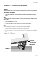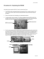
1
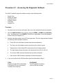
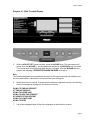
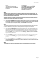
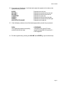
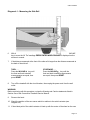
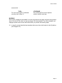
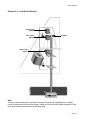
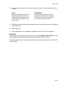
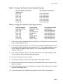
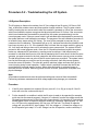
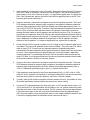
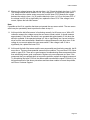
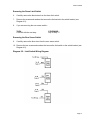
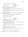
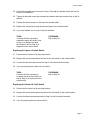
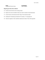
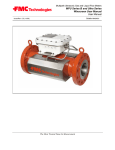
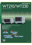
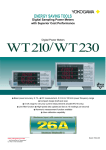
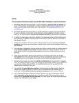
C944 Treadmill
C944 Treadmill
Warning: This service manual is for use by Precor trained service providers only.
If you are not a Precor Trained Servicer, you must not attempt to service any Precor Product;
Call your dealer for service.
This document contains information required to perform the majority of troubleshooting, and
replacement procedures required to repair and maintain this product.
This document contains general product information, software diagnostic procedures (when
available), preventative maintenance procedures, inspection and adjustment procedures,
troubleshooting procedures, replacement procedures and electrical block and wiring diagrams.
To move directly to a procedure, click the appropriate procedure in the bookmark section to the
left of this page. You may “drag” the separator bar between this page and the bookmark section
to change the size of the page being viewed.
© 2003 Precor Incorporated
Unauthorized Reproduction and Distribution Prohibited By Law
Page 1
C944 Treadmill
Section One - Things you Should Know
About This Appendix
Section One, Things You Should Know. This section includes technical specifications. Read
this section, as well as the C944 Treadmill Owner’s Manual, before you perform the maintenance
procedures in this manual.
Section Two, Software Features. Precor’s C944 Treadmill is programmed with several
diagnostic and setup features. This section contains the procedures you need to access the
diagnostic features on this treadmill.
Section Three, Checking Treadmill Operation. This section provides you with a quick way of
checking treadmill operation. Check treadmill operation at the end of a maintenance procedure
and when it is necessary to ensure that the treadmill is operating properly.
Section Four, Inspection and Adjustment Procedures. Perform inspection procedures when
a trouble symptom points to a particular problem and after removing and replacing major
components. Many maintenance problems can be fixed by adjusting various treadmill
components. This section also provides you with the step-by-step procedures required to make
these adjustments.
Section Five, Troubleshooting Procedures. The diagnostic and troubleshooting procedures
contained in this section should be performed when it is necessary to isolate a problem to a
particular component.
Section Six, Replacement Procedures. When a treadmill component must be replaced, go to
this section and follow the step-by-step procedures required to remove and replace the
component.
Section Seven, Technical Diagrams and Parts Lists. This section includes wiring diagrams,
and block diagrams for SCR and PWM C944 Treadmills.
General Information
For the latest exploded view, part number and part pricing information, visit the Precor dealer
website at “www.precor.com/Dealer”.
Page 2
C944 Treadmill
Technical Specifications
Physical Specifications
Length:
76 inches (193 cm)
Width:
Handrails 31.5 inches (80 cm)
Base 28.5 inches (72 cm)
44 inches (112 cm)
53 inches by 18 inches (135 cm by 46 cm)
2 hp continuous duty DC (120 Vac and 240 Vac
models)
0.5 to 12 mph (0.8 to 19 kph)
10 mph is equivalent to a 6 minute mile
-2% to +12% grade
50/60 Hz 120 Vac
50/60 Hz 240 Vac
276 lbs (119 kg)
326 lbs (147 kg)
Height:
Running surface:
Motor:
Speed:
Incline:
Power:
Weight:
Shipping Weight:
Page 3
C944 Treadmill
Procedure 2.1 - Accessing the Diagnostic Software
The C944 Treadmill's diagnostic software consists of the following modes:
•
•
•
•
•
•
Display Test
Manual Lift Adjust
Troubleshoot Lift
Software Version
Power Bits
Keypad Test
Procedure
1.
Plug the power cord into the wall outlet, then turn on the treadmill with the circuit breaker.
2.
With the PRECOR C944 banner scrolling, press the SPEED ▲, SPEED ▼ and INCLINE ▲
keys simultaneously or keys RESET,5,1,7,6.5.7.6,1, sequentially on units with standard
access codes (see Diagram 2.1).
3.
Watch the electronic display as the LED test progresses. This test is programmed to display
the following LED illumination sequence.
4.
a
Every LED on the left display window illuminates simultaneously
b
The lower row of the display window cycles from red to yellow to green.
c
Diagonal lines of illuminated LEDs sweep across the left display window.
d
The right display windows illuminate, then decrement from 8.8.8.8 to 0.0.0.0.
e
The function LEDs illuminate simultaneously and then extinguish.
f
Each function LED illuminates separately and then extinguishes.
If you do not observe the LED illumination sequences described in Step 3...
THEN...
Replace the upper PCA as described
in Procedure 5.2 of the Commercial
Treadmill Service Manual.
OTHERWISE...
The LED passed successfully;
continue with the next step.
Page 4
C944 Treadmill
Diagram 2.1. C944 Treadmill Display
5.
With the ADJUST LIFT banner scrolling, press the INCLINE keys. The running deck will
incline when the INCLINE ▲ key is pressed and decline as the INCLINE ▼ key is pressed.
The running deck will stop moving when the key is released. After the INCLINE keys are
pressed, the message, PRESS ENTER WHEN FINISHED will scroll by.
Note:
The following diagnostic test automatically searches for the upper and lower limit switches and
the zero sense switch. It also detects a non-functional (non-moving) lift.
6.
Watch the electronic console. If the three limit switches are adjusted correctly, the following
series of messages is displayed on the electronic console:
GOING TO TWELVE PERCENT
AT TWELVE PERCENT
GOING TO UPPER LIMIT
GOING TO NEG TWO PERCENT
AT NEGATIVE TWO PERCENT
GOING TO LOWER LIMIT
GOING TO ZERO
7.
If all of the messages listed in Step 6 are displayed on the electronic console...
Page 5
C944 Treadmill
THEN...
The treadmill lift switches are
calibrated correctly, press ENTER
to continue.
OTHERWISE...
Press RESET to return to the PRESS
ENTER FOR PROGRAMS prompt,
then calibrate the lift systems
described in Procedure 4.1.
Note:
Software revision changes can only be made by replacing the currently installed PROM. The
revision of the software does not change by resetting the system. Some software updates may
require the user to perform a system reset.
Software numbers are invaluable for tracking and identifying problems and keeping abreast of
changes to the operation and features of the product.
8.
The message VERSION scrolls across the display and will continue to do so while you hold
any key down. When the key is released you will see the software version number displayed
in the middle right seven-segment display. Press ENTER to exit this mode.
Note:
The following mode allows manual control of the motor speed while displaying the power bits. It
is useful in determining if the system is having difficulties running the motor and belt.
9.
The message POWER BITS scrolls across the display once. Two numbers appear in the
right upper and right middle seven-segment displays. The upper number is the power bits
and the lower number is the requested speed in miles-per-hour (or kilometers-per-hour).
Press the SPEED ▲ key to start the motor. The SPEED ▲, SPEED ▼, STOP and ENTER
keys are active in this mode.
10. Press the SPEED keys while you watch the right display window. The power bits number
increments as the SPEED ▲key is pressed and decrements as the SPEED ▼ key is
pressed.
11. Press either the STOP key or the ENTER key to stop the motor and exit this diagnostic.
Press the SPEED ▼ key until zero MPH (or KPH) is attained if you wish to stop the motor but
not exit this diagnostic.
Note:
The keypad test is useful for troubleshooting stuck or non-operating keys on the keypad.
Page 6
C944 Treadmill
12. Press each key listed below. Verify that each single dot expands to four dots as the
appropriate key is pressed.
ENTER
INCLINE ▼
INCLINE ▲
STOP/RESET
SPEED ▼
SPEED ▲
QUICK START/CHANGE
Expands the far left dot.
Expands the second dot from the left.
Expands the third dot from the left.
Expands the center dot.
Expands the third dot from the right.
Expands the second dot from the right.
Expands the far right dot.
13. If the left display window column illuminates appropriately as each key is pressed...
THEN...
The keypad test passed successfully;
continue with the next step.
OTHERWISE...
Troubleshoot the upper PCA and
keypad as described in Procedure 5.1
of this appendix.
14. End the keypad test by pressing the INCLINE ▼ and SPEED ▲ keys simultaneously.
Page 7
C944 Treadmill
Procedure 2.2 - Displaying the Treadmill Odometer
This procedure displays total distance (in miles or kilometers) the treadmill has operated. The
odometer cannot be reset.
Note:
The odometers get updated at the end of the course. If a user shuts off the unit while in the
middle of a course, the odometer will not be updated and the user will have essentially lost the
mileage for that session. Pressing RESET displays the PRECOR C944 banner and accumulates
the mileage.
Procedure
1.
Plug the power cord into the wall outlet, then turn on the treadmill with the circuit breaker.
2.
With the PRECOR C944 banner scrolling, press the INCLINE ▲ and SPEED ▲ keys
simultaneously or keys RESET,6,5, sequentially on units with standard access codes.
Note:
The right display window displays total miles or kilometers on the treadmill (see
Diagram 2.2). The top display window shows the most significant bits of the number; the lower
display window shows the least significant bits of the number. The number displayed is
102,187,723 (in miles or kilometers).
3.
Press ENTER to return to the PRECOR C944 banner.
Diagram 2.2. - Odometer Display
0 0 0 1
0 2 1 8
7 7 2 3
Page 8
C944 Treadmill
Procedure 2.3 - Changing Club Settings
This procedure allows you to change the following club settings:
•
English Standard /Metric Units
Selecting United States standard units causes data to be displayed in feet, miles and
pounds. Data is displayed in meters, kilograms and kilometers if metric units are selected.
•
Maximum Speed
This selection is used to artificially limit the maximum speed the treadmill can attain when a
user is working out.The C944 Treadmill can attain an absolute maximum speed of 12.0
MPH (20.0 KPH) for PWM units and 10.0 MPH (16.0 KPH) for SCR units. This speed selection mode cannot exceed these speeds, but rather speeds may be selected that are lower
than these maximums.
•
Maximum Workout Time
This club selection is used to limit the maximum workout time the treadmill may be used
during a workout. The time may range from a minimum of 10 minutes to an absolute maximum of 240 minutes. The default from the factory is 60 minutes.
Procedure
1.
Plug the power cord into the wall outlet, then turn on the treadmill with the circuit breaker.
2.
If you wish to verify the measurement standard the treadmill is currently using continue with
the next step. If you wish to change the measurement standard the treadmill is using, skip to
Step 5.
Checking the Measurement Standard
3.
Press ENTER until the WEIGHT indicator light appears.
4.
Watch the number displayed in the left display window while you press the SPEED ▲ key
five or six times.
Note:
If the treadmill is using United States standard units, the numbers in the left display window are
repeatable multiples of 5 (such as 160, 165, 170, 175, etc.). Otherwise, the treadmill is using
metric units.
Page 9
C944 Treadmill
Changing the Measurement Standard
5.
With the PRECOR C944 banner scrolling, press the SPEED ▲ and QUICK START/
CHANGE keys simultaneously or keys RESET,5,6,5,1,5,6,5, sequentially on units with
standard access codes. A message indicating the last selected units (either U. S.
STANDARD UNITS or METRIC UNITS) scrolls across the display.
6.
Use the SPEED or INCLINE keys to select the alternate measurement standard.
Note:
Holding the INCLINE UP and CHANGE keys at the banner may cause the last selected units to
change if the INCLINE UP key is released before the CHANGE key.
Selecting Maximum Workout Speed
For PWM treadmills, the maximum workout speed limit is between either 1 and 12 MPH or 1 and
20 KPH. Maximum workout speed limits for SCR C944 treadmills range between 1 and 10 MPH
or 1 and 16 KPH.
7.
With the last currently selected maximum speed displayed on the L.E.D. matrix, use the
SPEED or INCLINE keys to designate a workout speed limit. Press ENTER when the
desired speed appears.
Selecting Maximum Workout Time
8.
With the last currently selected maximum time displayed on the L.E.D. matrix, use the
SPEED or INCLINE keys to designate a workout time limit. Press ENTER when the desired
time appears.
Page 10
C944 Treadmill
Procedure 2.4 - Documenting Software Problems
When a problem is found with either the software or upper or lower PCA’s, record the information
listed below. If you isolated the problem to either the PROM, upper PCA, or lower PCA, include
the information you recorded with the malfunctioning PROM or PCA when you ship it to Precor.
When a problem occurs, record the following information:
•
•
Model and serial number
Software version number
Note
Determine the version number of the PROM as described in Procedure 2.1 (or by looking at the
label on the PROM).
•
•
•
User and program number running when the problem occurred
A description of:
a
What happened or failed to happen.
b
The action taken by the user just before the problem occurred.
c
Problem-related information (such as how far into the program the problem occurred,
the work level being used when the problem occurred, etc.).
The frequency of occurrence.
Page 11
C944 Treadmill
Section Three - Checking Treadmill Operation
This section provides you with a quick method of checking treadmill operation. Check treadmill
operation at the end of a maintenance procedure and when it is necessary to ensure that the
treadmill is operating properly.
Procedure
4.
Plug the power cord into the wall outlet, then turn on the treadmill with the circuit breaker.
5.
Place the treadmill in Manual Mode. Adjust the speed of the running belt to 2–3 mph
Operate the treadmill for at least 5 minutes.
a.
Concentrate on the feel of the running belt and the sound of the drive motor and rollers.
Be on the alert for unusual noises, smells, or vibrations.
b.
On SCR units, measure and log the AC input current under loaded and unloaded conditions. On PWM units, log the power bits under loaded and unloaded conditions.
c.
Observe the LEDs on the electronic console. Make sure that each LED lights as the information corresponding to that LED is displayed on the electronic console.
3.
Press the STOP key. When the treadmill comes to a stop, view the electronic console as the
treadmill scans time, speed, distance and percent of lift.
4.
Press the INCLINE ▲ key while viewing the electronic console. Confirm that the running
bed inclines and the incline display increments to twelve percent as the INCLINE ▲ key is
pressed.
5.
Press the INCLINE ▼ key while viewing the electronic console. Confirm that the running bed
returns to a level position and the incline display decrements to minus two percent as the
INCLINE ▼ key is pressed.
Turn off the treadmill with the circuit breaker, then unplug the treadmill from the wall outlet.
Page 12
C944 Treadmill
Procedure 4.1 - Calibrating the Lift Limit Switches
WARNING
Always turn off the circuit breaker and unplug the treadmill before you remove the treadmill hood.
1.
If the treadmill is not already at zero percent incline, press any key when the CALIBRATE
LIFT PRESS ANY KEY prompt is displayed.
2.
Using the ruler, measure the distance between the floor and the top of the front and back
ends of the side rail (see Diagram 4.1).
Note:
The distance between the floor and the top of the front end of the side rail should be 9 inches.
3.
If the distances recorded in the previous step are equal to within 1/4" . . .
THEN . . .
Skip to Step 17.
OTHERWISE . . .
Continue with the next step.
4.
With the PRECOR C944 banner scrolling, press the SPEED ▲, SPEED ▼ and INCLINE ▲
keys simultaneously or keys 4,5,1,7,6.5.7.6,1, sequentially on units with standard access
codes.
5.
Press ENTER when the display test starts.
Page 13
C944 Treadmill
Diagram 4.1 - Measuring the Side Rail
6.
With the ADJUST LIFT prompt displayed, press either the INCLINE ▲ or ▼ INCLINE
key to move the lift. The message PRESS ENTER WHEN FINISHED is displayed on the
electronic console.
7.
If the distance measured at the front of the side rail is larger than the distance measured at
the back of the side rail . . .
THEN . . .
Press the INCLINE ▼ key until
the front and back treadmill
measurements are equal; then
press RESET.
8.
OTHERWISE . . .
Press the INCLINE ▲ key until the
front and back treadmill measurements
are equal; then press RESET.
Turn off the treadmill with the circuit breaker, then unplug the power cord from the wall
outlet.
WARNING
Before continuing with this procedure, review the Warning and Caution statements listed in
Section One of the Commercial Treadmill Service Manual.
9.
Remove the hood.
10. Check the position of the zero sense switch in relation to the switch actuator (see
Diagram 4.2)
11. If the widest point of the switch actuator is lined up with the center of the wheel on the zero
Page 14
C944 Treadmill
sense switch . . .
THEN . . .
The zero sense switch is calibrated
correctly; skip to Step 16.
OTHERWISE . . .
The switch bracket must be adjusted;
continue with the next step.
WARNING
When power is applied to the treadmill, the wires connected to the upper and lower limit switches
carry 110 volts (or 220 volts if you are servicing a 220-volt treadmill). Turn off the treadmill and
unplug the power cord from the wall outlet before you perform the following steps.
12. Loosen the socket head bolts and washers that secure the switch bracket to the lift platform
(see Diagram 4.2).
Page 15
C944 Treadmill
Diagram 4.2 - Limit Switch Bracket
Lower Limit
Switch
Zero Sense
Switch
Actuator
Upper Limit
Switch
Note:
The zero sense switch can be actuated if the center of the wheel is slightly above or slightly
below the widest point of the switch actuator. However, for best results, adjust the position of the
zero sense switch as described in the following step.
Page 16
C944 Treadmill
13. If the center of the wheel on the zero sense switch is above the widest point of the switch
actuator . . .
THEN . . .
Move the switch bracket down until
the widest part of the actuator is
centered on the wheel on the zero
sense switch; then continue with
the next step.
OTHERWISE . . .
Move the switch bracket up until the
widest part of the actuator is centered
on the wheel on the zero sense switch;
then continue with the next step.
14. Tighten the socket head bolts and washers that secure the switch bracket to the lift platform
(see Diagram 4.2).
15. Replace the hood.
16. Check the operation of the treadmill as described in Section Three of this appendix.
IMPORTANT
If the electronic console displays the diagnostic message LIFT ERROR PRESS STOP when you
incline and decline the running bed to its maximum limits, repeat this procedure.
If readjusting the position of the switch actuator does not fix the problem, refer to Procedure 2.4
in this appendix.
Page 17
C944 Treadmill
Procedure 5.1 - Troubleshooting the Keypad and Upper PCA
If the function keys on the electronic console are unresponsive, the problem may be either the
upper PCA or keypad. This troubleshooting procedure gives you the information you need to
determine which of these components is malfunctioning.
Procedure
1.
Set the circuit breaker in the “off” position.
WARNING
Before continuing with this procedure, review the Warning and Caution statements listed in
Section One of the Residential Treadmill Service Manual.
2.
Remove the screws that secure the upper display assembly to the upper handrail. Carefully,
pull some excess interconnect cable out from the targa upright. Rotate the display housing,
so that the rear of the upper PCA is facing upward, and set the display housing on the upper
handrail.
3.
Attach the wrist strap to your arm, then connect the ground lead of the wrist strap to the
treadmill frame.Set the voltmeter to a range that will conveniently read +6 Vdc.
U13
Diagram 5.1 - Upper PCA Component Layout
U3
26
RN4
2
J2
J1
25
RN5
1
J4
J5
4.
Set the voltmeter to a range that will conveniently read +6 Vdc.
5.
Set the circuit breaker in the “on” position.
6.
Use a DVM, set for DC volts, and read between pin 6 of J3 and the each of the pins in Table
5.1 (no keys pressed) and Table 5.2 (with the appropriate key pressed)...
Page 18
C944 Treadmill
Table 5.1 - Voltage Test Points (Function Keys Not Pressed)
Place the positive lead of the
voltmeter on...
Pin 3 of J3
Pin 4 of J3
Pin 5 of J3
Pin 7 of J3
Pin 8 of J3
Pin 9 of J3
Pin 10 of J3
The voltmeter should read...
5 Vdc ± 500 mVdc
5 Vdc ± 500 mVdc
5 Vdc ± 500 mVdc
5 Vdc ± 500 mVdc
5 Vdc ± 500 mVdc
5 Vdc ± 500 mVdc
5 Vdc ± 500 mVdc
Table 5.2 - Voltage Test Points (Function Keys Pressed)
Place the positive
voltmeter lead on...
Pin 3 of J3
Pin 4 of J3
Pin 5 of J3
Pin 7 of J3
Pin 8 of J3
Pin 9 of J3
Pin 10 of J3
At the display
enclosure, press...
ENTER
INCLINE DOWN
INCLINE UP
STOP
SPEED DOWN
SPEED UP
QUICK START
The voltmeter should
read between...
0 Vdc and 500 mVdc
0 Vdc and 500 mVdc
0 Vdc and 500 mVdc
0 Vdc and 500 mVdc
0 Vdc and 500 mVdc
0 Vdc and 500 mVdc
0 Vdc and 500 mVdc
7.
If the voltage readings match those listed in Tables 5.1 and 5.2 and one or more keys do not
function, replace the upper PCA.
8.
If the voltage readings in Table 5.1 are incorrect, disconnect the keypad cable from the key
pad connector and repeat the voltage measuremnts in 5.1. If the voltage readings are now
correct, replace the display housing (keypad). If the voltage readings are still incorrect,
replace the upper PCA.
9.
If the voltage readings in Table 5.1 are correct and one or more voltage readings in Table
5.2 are incorrect, replace the display housing (keypad).
10. Set the circuit breaker in the “off” position.
11. If necessary, carefully re-connect the keypad cable to the keypad connector.
12. Remove the ground lead of the wrist strap from the treadmill frame, then remove the wrist
strap from your arm.
13. Position the display enclosure on the display plate. Install the screws that secure the display
enclosure to the display plate.
14. Check the operation of the treadmill as described in Section Three of this appendix.
Page 19
C944 Treadmill
Procedure 5.2 - Troubleshooting the Lift System
Lift System Description:
The lift system on these units consists of an AC line voltage driven lift motor (120 Vac or 240
Vac), a hall effect rotation sensor and three position location switches. The lift system orients
itself by locating the zero sense switch when the treadmill is powered up. When the zero sense
switch is activated the system recognizes that physical position as 0% incline. If the zero sense
switch is activated when the treadmill is powered up, the system proceeds directly into the
normal program mode. If the zero sense switch is not activated when the treadmill is powered up,
the system performs a self calibration procedure. The purpose of the self calibration procedure is
to locate the zero sense switch (0% incline). The user will be prompted to press any key to
commence the lift calibration. The treadmill will go up 4%, because the lowest the treadmill could
have been at power up is -3%. If the treadmill does not locate the zero sense switch by going up
4%, it will stop and then go down until it activates the zero sense switch. The system will then
proceed to the normal program mode. Once the 0% lift position has been located, the system
tracks any subsequent lift operations by counting motor revolutions. A hall effect sensor is
mounted on a bracket that is next to a hub that is attached to the lift motor shaft. As the lift motors
operates, a magnet mounted in the hub, passes the hall effect sensor once per motor revolution.
The hall effect sensor send one pulse to the lift control system per revolution. The system knows
how far the lift travels per revolution and by counting revolutions (hall effect sensor pulses),
knows the current lift position. The other two position switches (upper and lower limit) do not
come into play during normal operation. If either switch is activated it means that the lift has
moved beyond it’s normal range of motion. When either limit switch is activated, power is
removed from the lift motor. Removing power from the lift motor, protects the lift system from
physical damage.
Note:
All resistance measurements must be performed with power removed from the treadmill.
Performing resistance measurements with voltage applied may damage your ohmmeter.
Procedure
1.
If the lift motor operates but creates a lift error (error 40, 41 or 43) go to step 8. If the lift
motor will not move continue with step 2.
2.
Put the treadmill in a condition in which the lift motor is ready to be operated (for example,
quick start into the manual program). Using an AC voltmeter, monitor the voltage across the
lift capacitor and press one of the incline keys. Approximately 1.4 times the AC input voltage
should appear on the lift capacitor when an incline key is pressed. Approximately 170 Vac
on a 120 Vac unit or approximately 340 Vac on a 240 Vac unit. The actual lift capacitor
voltage will vary with the AC input voltage. If AC line voltage or 1.4 times line voltage is on
the lift capacitor go to step 6. If no AC voltage is on the lift capacitor, continue with step 3.
Page 20
C944 Treadmill
3.
Set the treadmill circuit breaker in the “off” position. Remove the 2 amp lift fuse (F2) from the
lower PCA. Using an ohmmeter, measure the fuse resistance. The fuse should measure
approximately 1Ω or less. If the fuse is open (∞) or significantly higher than 1Ω, replace the
fuse. If the fuse was bad, perform the test in step 4 before applying power to the lift. If the
fuse was good continue with step 5.
4.
Using an ohmmeter, measure the resistance across the lift capacitor terminals. The Lower
PCA resistance should be extremely high (megohms), the capacitor resistance should be
extremely high (megohms) and the lift motor winding should read approximately 34Ω (120
Vac units) or 122Ω (240 Vac units). Therefore, if the measurement is significantly lower than
34Ω or 122Ω, disconnect both red leads from the lift capacitor. Measure the resistance
between the black leads on the lift capacitor and red lead to the lower PCA. If it measures
significantly low, replace the lower PCA. Measure the resistance between the black leads on
the lift capacitor and red lead to the lift motor. If it measures significantly low, replace the lift
motor. Measure the resistance between the black leads on the lift capacitor and other
terminal of the lift capacitor. If it measures significantly low, replace the lift capacitor.
5.
At this point the lift fuse is good, but there is no AC voltage on the lift capacitor when the lift
is actuated. There are three potential causes for this condition. They are lower PCA, ribbon
cable or upper PCA. There are not any adequate means of troubleshooting these
components other than substituting known good components. Replace only one component
at a time. If the component that you replaced does not correct the problem, replace the
original component. Try substituting the lower PCA first, the ribbon cable second and the
upper PCA third. If you have performed all of the above procedures and have been unable
to correct the problem, call Precor Customer Support.
6.
Using an ohmmeter, measure the resistance across the lift capacitor terminals. The lower
PCA resistance should be extremely high (megohms), the capacitor resistance should be
extremely high (megohms) and the lift motor winding should read approximately 34Ω or
122Ω. If it measures significantly high or open (∞), replace the lift motor.
7.
If the resistance measurement in step 6 was approximately 34Ω (120 VAC units) or 122Ω
(240 VAC units), replace the lift capacitor. If you have performed all of the above procedures
and have been unable to correct the problem, call Precor Customer Support.
8.
Typically, when the lift is able to physically move but causes a lift error, the problem is in the
lift position identification system (rotation sensor and zero sense switch).
9.
Connect a DC voltmeter between the white wire (term. 2 of J3) and the red wire (term. 4 of
J3) on the lower PCA. Set the treadmill circuit breaker in the “on” position and slowly rotate
the hub at the bottom of the lift motor by hand. The DC voltmeter should read approximately
0 Vdc when the magnet in the hub is not near the hall effect sensor and approximately 5
VDC when the magnet is near the hall effect sensor. If the voltage switches between 0 and
5 Vdc as the magnet passes the hall effect sensor continue with step 11.
Page 21
C944 Treadmill
10. Measure the voltage between the red wire (term. 4 of J3) and the black wire (term 1 of J3).
The voltage should read a constant 5 Vdc. If the voltage is 0 or significantly lower than 5
Vdc, disconnect the rotation sensor connector from the lower PCA. Measure the voltage
between the red wire (term. 4 of J3) and the black wire (term 1 of J3) on the lower PCA. If
the voltage is still 0 Vdc or significantly low, replace the lower PCA. If the voltage is now
correct, replace the hall effect sensor.
Note:
If possible set the lift in a position that does not operate the zero sense switch. The zero sense
switch may be operated by hand to perform the tests in step 11.
11. At this point the hall effect sensor is functioning normally, but lift errors occur. With a DC
voltmeter measure the voltage across the zero sense (center) switch. It should measure
approximately 0 Vdc when the switch is not operated and approximately 5 Vdc when the
switch is operated. If the operated voltage is 0 Vdc or significantly low, remove both blue
wires from the zero sense switch. Measure the voltage between the two blue wires. If the
voltage is now correct replace the zero sense switch. If the voltage is still O Vdc or
significantly low, replace the lower PCA.
12. At this point the hall effect sensor and the zero sense switch are functioning normally, but lift
errors occur. There are three potential causes for this condition. They are lower PCA, ribbon
cable or upper PCA. There are no good means of troubleshooting these components other
than substituting known good components. Replace only one component at a time. If the
component that you replaced does not correct the problem, replace the original component.
Try substituting the lower PCA first, the ribbon cable second and the upper PCA third. If you
have performed all of the above procedures and have been unable to correct the problem,
call Precor Customer Support.
Page 22
C944 Treadmill
Procedure 5.3 - Troubleshooting the Speed Sensor
Note:
The speed sensor is a hall effect sensor that emits a pulse when a flywheel lobe passes it. The
speed control circuit processes the pulse train emitted by the speed sensor. The speed sensor
signal is a real time representation of the operating speed of the treadmill. The speed control
circuit compares the real time speed (speed sensor output) with the speed that it expects the
treadmill to be operating at and acts accordingly to control treadmill speed or initiate an error
code sequence, if necessary. Typically, if a problem exists with the speed sensor the drive motor
will operate (perhaps only briefly) before a speed related error occurs (errors 20-26).
Note:
Some speed sensor have red, black and white wires and some have red, black and green wires.
The following procedures will assume red, black and white wires. If the speed sensor on the unit
under test has red black and green wires, perform your test procedures using the green wire
instead of the white wire. The white and green wires serve the same function.
1.
Check the distance between the end of the speed sensor and a flywheel lobe. the distance
should be approximately .050 inches. Adjust the distance between the speed semsor and
flywheel if required.
2.
Set the treadmill circuit breaker in the “on” position. Using a DC voltmeter, measure the
voltage between terminal 1 of J5 (red wire) and terminal 3 of J5 (white wire) on the lower
PCA. Slowly, rotate the drive motor flywheel. The voltage should read approximately 5 Vdc
as a flywheel lobe passes the speed sensor and approximately 0 Vdc when a flywheel lobe
is not in front of the speed sensor.
3.
If the voltage in step 1 is correct, go to step 6. If the voltage in step 1 is 0 Vdc or significantly
low when a flywheel lobe passes the speed sensor, continue with step 4.
4.
Measure the voltage between terminal 1 of J5 (red wire) and terminal 4 of J5 (black wire) on
the lower PCA. The voltage should read approximately 5 Vdc.
5.
If the voltage is missing or significantly low, disconnect the speed sensor plug from the lower
PCA. Measure the voltage between pins 1 & 4 of the J5 plug on the lower PCA. If the
voltage is approximately 5 Vdc, replace the speed sensor. If the voltage is missing or
significantly low, replace the lower PCA.
6.
At this point the speed sensor output is good, but a speed error occurs. There are three
potential causes for this condition. They are ribbon cable, upper PCA or lower PCA. There
are no good means of troubleshooting these components other than substituting known
good components. Replace only one component at a time. If the component that you
replaced does not correct the problem, replace the original component. Try substituting the
ribbon cable first, the upper PCA second and the lower PCA third.
7.
If you have performed all of the above procedures and have been unable to correct the
problem, call Precor Customer Support.
Page 23
C944 Treadmill
Procedure 5.4 - Troubleshooting the External A.C. Power
Source
It is extremely important that any Precor treadmill be connected to and operated on a dedicated
20 amp A.C. circuit. A 20 amp dedicated circuit is defined as: a circuit fed by a 20 amp circuit
breaker that feeds a single load. A treadmill operating from a non-dedicated circuit or a circuit
breaker of less than 20 amps capacity will not have the necessary power available to operate
normally under higher load conditions. The lack of available power can cause any number of
symptoms ranging from numerous intermittent (seemingly inexplicable) error conditions, poor
speed control, or tripping the house circuit breaker.
If any of the above symptoms exist the external A.C. circuit must be checked and confirmed to be
a 20 amp dedicated circuit before troubleshooting the treadmill.
In addition the A.C. voltage must be checked. Nominal A.C. operating voltage on 120 Vac circuits
is 105 Vac to 120 Vac. Nominal A.C. operating voltage on 240 Vac circuits is 208 Vac to 240
Vac.
For operator safety considerations and to minimize electrostatic discharge conditions the A.C.
frame ground continuity must also be verified to be a low resistance connection to the A.C.
distribution ground bar.
Important
If the A.C. circuit feeding a treadmill is found to be a non-dedicated circuit or a circuit equipped
with a circuit breaker with a capacity of less than 20 amps, the A.C. circuit must be corrected to
be a 20 amp dedicated circuit before any reliable troubleshooting can be performed on the
treadmill. More importantly, a non-dedicated circuit may constitute a safety hazard to the
treadmill operator.
120 Vac Systems
120 Vac distribution systems utilize a single pole circuit breaker (hot lead) and a neutral lead
connected to a common neutral (ground) bar. The A.C. safety ground (green wire) is connected
to a separate ground bar in the distribution system.
The most common problems found are (1) the circuit is fed by a circuit breaker of less than 20
amp capacity, (2) the circuit breaker correctly feeds a single A.C. outlet but the neutral is
common between several A.C. outlets and (3) both the hot and neutral leads feed several A.C.
outlets. The appropriate correction action or actions (see below) must be followed if any of the
above conditions exist. Corrective actions should only be undertaken by a licensed
electrician.
1.
The circuit breaker feeding the treadmill is not a 20 amp circuit breaker.
If the circuit breaker is greater than 20 amps, the circuit breaker should be replaced with a
20 amp circuit breaker. If the circuit breaker is less than 20 amps the circuit breaker must be
replaced with a 20 amp circuit breaker and the wiring from the A.C. distribution must be
capable of safely handing 20 amps. If the A.C. wiring is under sized, it must be replaced
with wire capable of safely handling 20 amps. Please, refer to local electrical codes when
determining the appropriate wire size for a 20 amp circuit.
Page 24
C944 Treadmill
2.
The circuit breaker correctly feeds a single A.C. outlet but the neutral is common
between several A.C. outlets.
The common neutral lead must be removed from treadmill’s A.C. outlet and a new neutral
lead from the treadmill’s A.C. outlet to the A.C. neutral distribution bar must be added.
3.
Both the hot and neutral leads feed several A.C. outlets.
Both the common neutral and hot leads must be removed from treadmill’s A.C. outlet and a
new neutral lead and hot lead from the treadmill’s A.C. outlet to the A.C. neutral distribution
bar and circuit breaker must be added.
240 Vac Systems
240 Vac distribution systems utilize a double pole circuit breaker (two hot leads) The A.C. safety
ground (green wire) is connected to a ground bar in the distribution system.
The most common problems found are (1) the circuit is fed by a circuit breaker of less than 20
amp capacity and (2) both the hot leads feed several A.C. outlets. The appropriate correction
action or actions (see below) must be followed if any of the above conditions exist. Corrective
actions should only be undertaken by a licensed electrician.
1.
The circuit breaker feeding the treadmill is not a 20 amp circuit breaker.
If the circuit breaker is greater than 20 amps, the circuit breaker should be replaced with a
20 amp circuit breaker. If the circuit breaker is less than 20 amps the circuit breaker must be
replaced with a 20 amp circuit breaker and the wiring from the A.C. distribution must be
capable of safely handing 20 amps. If the A.C. wiring is under sized, it must be replaced
with wire capable of safely handling 20 amps. Please, refer to local electrical codes when
determining the appropriate wire size for a 20 amp circuit.
2.
Both the hot leads feed several A.C. outlets.
Both hot leads must be removed from treadmill’s A.C. outlet and two new hot leads from the
treadmill’s A.C. outlet to the circuit breaker must be added.
A licensed electrician may use the followings hints to determine if an A.C. service is dedicated.
1.
If, on a 120 Vac system, the A.C. distribution panel contains more circuit breakers than
neutral leads, the system has shared neutral leads and is not dedicated.
2.
If an A.C. outlet (120 or 240 Vac) has multiple hot and/or neutral leads, it is not a
dedicated.If either of the above conditions exist, the system is not dedicated. However,
absence of the above conditions does not necessarily mean that the system is dedicated. If
any doubt exists about A.C. systems dedication, point to point tracing of the A.C. wiring may
be the only way to prove system dedication.
Page 25
C944 Treadmill
Procedure 6.1 - Replacing the Lift Motor, Rotation Sensor or
Magnet Hub
Note:
If you need to replace a lift motor that utilizes a hall effect rotation sensor, remove the magnet
hub and rotation sensor bracket from the defective lift motor and mount them on the new lift
motor. Unless the magnet and rotation sensor are defective, do not remove them from their
mounting positions on the magnet hub and sensor bracket. Replacement lift motors are not
furnished with the hall effect rotation sensor.
WARNING
Always turn off the circuit breaker and unplug the treadmill before you remove the treadmill hood.
Removing the Lift Motor
1.
Remove the hood.
2.
Remove the red lift motor lead from the lift motor capacitor, but leave the remaining red wire
connected to the capacitor terminal.
3.
Remove the black lift motor lead from the lift motor capacitor, but leave the remaining black
wire connected to the capacitor terminal.
4.
Disconnect the connector on the white lift motor lead.
5.
Remove the revolution sensor plug from the J2 connector jack on the lower PCA.
Note:
When the revolution sensor wire assembly is disconnected from the lower PCA, the zero sense
switch must be disconnected as well.
6.
Disconnect the two blue wires on the rotation sensor wire assembly from the zero sense
switch terminals.
7.
Place the treadmill on its left side.
8.
Remove the two shoulder screws and nuts that secure the lift motor to the treadmill frame
and lift platform. Remove the lift motor and set it aside.
9.
Remove the set screw that secures the magnet hub to the lift motor. Set aside the magnet
hub.
Page 26
C944 Treadmill
Diagram 6.1 - Exploded view of the Lift Motor (with Rotation Sensor)
Lift Motor
Rotation Sensor
Mounting Bracket
Rotation Sensor
Magnet Hub
Magnet
Page 27
C944 Treadmill
Replacing the Magnet
10. Remove the set screw that secures the magnet to the magnet hub. Discard the magnet.
Note:
When you position the magnet in the magnet hub, place the north pole towards the center of the
magnet hub. The north pole of the magnet should be marked with a spot of white paint. If the
magnet on the treadmill you are servicing is not marked, use either a compass or another
magnet to determine the north pole.
11. Position the new magnet in the magnet hub.
12. Tighten the set screw that secures the magnet to the magnet hub.
13. If you are replacing the revolution sensor...
THEN...
Continue with the next step.
OTHERWISE...
Skip to Step 19.
14. Remove the screw and washer that secure the rotation sensor to the sensor bracket (see
Diagram 6.1).
15. Position the revolution sensor at its mounting location.
16. Position the screw and washer that secure the rotation sensor to the sensor bracket. Torque
the screw to 8 in-lbs.
17. If you are replacing the lift motor you removed earlier in this procedure...
THEN...
Continue with the next step.
OTHERWISE...
Skip to Step 25.
Removing and Replacing the Rotation Sensor Bracket
18. Remove the two nuts that secure the sensor bracket to the lift motor.
19. Position the sensor bracket removed in the previous step on the lift motor.
20. Replace the two nuts that secure the sensor bracket to the lift motor.
21. Position the magnet hub on the lift motor so that it is flush with the speed sensor bracket.
22. Replace the set screw that secures the magnet hub to the lift motor.
Page 28
C944 Treadmill
Replacing the Lift Motor
23. Extend the lift motor actuator 1/2” by turning the magnet hub.
Note:
To extend the lift motor actuator faster, place a screwdriver shaft in the lower mounting hole of
the lift motor and rotate the lift motor tube.
24. Position the lift motor at its mounting location.
Note:
When you perform Step 25, replace the lower screw and nut first.
25. Replace the two shoulder screws and nuts that secure the lift motor to the treadmill frame.
Note:
The original nuts used to mount the lift motor are Kep nuts, which do not require a separate
washer. If you do not use Kep nuts to mount the lift motor, use washers when you mount the lift
motor to the treadmill frame.
26. Return the treadmill to an upright position.
27. Connect the black lift motor lead to the terminal of the lift motor capacitor that already has a
black wire.
28. Connect the red lift motor lead to the terminal of the lift motor capacitor that already has a
red wire.
29. Connect the connector on the white lift motor lead that connects the lift motor to pin 4 of
lower PCA connector J3.
30. Connect the molex connector on the revolution sensor wire assembly to connector J2 on the
lower PCA.
31. Connect the two blue wires on the revolution sensor wire assembly to the terminals on the
zero sense switch terminals.
32. Calibrate the treadmill lift assembly as described in Procedure 4.1 of this appendix.
33. Check the operation of the treadmill as described in Section Three of this appendix, then
replace the hood as described in Procedure 5.1 of the Commercial Treadmill Service
Manual.
Page 29
C944 Treadmill
Procedure 6.2 - Replacing the Limit Switches, Actuator Shaft
or Switch Bracket
Note:
The limit switches and the actuator shaft are mounted on the switch bracket (see Diagram 4.2).
WARNING
Always turn off the circuit breaker and unplug the treadmill before you remove the treadmill hood.
Procedure
1.
Remove the hood.
2.
If you are removing the actuator shaft...
THEN...
Skip to Step 12 (to remove the actuator
shaft), Step 6 (to remove
the down limit switch) or Step 9 (to
remove the zero sense switch.
OTHERWISE...
Continue with the next step.
Removing the Upper Limit Switch
WARNING
When power is applied to the treadmill, the wires connected to the upper and lower limit switches
carry high voltage. Turn off the treadmill and unplug the power cord from the wall outlet before
you perform the following steps.
3.
Carefully remove the red wires from the upper limit switch.
Note:
See Diagram 6.2 for limit switch wiring.
4.
Remove the screws and washers that secure the limit switch to the switch bracket.
5.
If you are removing more than one limit switch...
THEN...
Continue with the next step to
remove the down limit switch or
Step 9 to remove the zero sense
switch
OTHERWISE...
Skip to Step 11.
Page 30
C944 Treadmill
Removing the Down Limit Switch
6.
Carefully remove the black wires from the down limit switch.
7.
Remove the screws and washers that secure the limit switch to the switch bracket (see
Diagram 4.2).
8.
If you are removing the zero sense switch...
THEN...
Continue with the next step.
OTHERWISE...
Skip to Step 11.
Removing the Zero Sense Switch
9.
Carefully remove the blue wires from the zero sense switch.
10. Remove the two screws and washers that secure the limit switch to the switch bracket (see
Diagram 4.2).
Diagram 6.2 - Limit Switch Wiring Diagram
Page 31
C944 Treadmill
11. If you are removing the actuator shaft or switch bracket...
THEN...
Continue with the next step.
OTHERWISE...
Skip to Step 26.
Removing the Actuator Shaft and Switch Actuator
12. Remove the screw that secures the switch actuator to the actuator shaft. Set aside the
screw and switch actuator.
13. Remove the shoulder screw that connects the actuator shaft and actuator block to the lift
platform. (See Diagram 6.3)
Note:
If necessary, hold the actuator shaft with the pliers and support the actuator block firmly with your
hand when you perform Step 14.
14. Unscrew the actuator shaft from the actuator block. Set aside the actuator block.
15. Slide the actuator shaft from the switch bracket.
16. If you are removing the switch bracket...
THEN...
Continue with the next step.
OTHERWISE...
Skip to Step 20.
Removing and Replacing the Switch Bracket
17. Remove the socket head screws and washers that secure the switch bracket to the lift motor
platform. Set aside the switch bracket.
18. Position the switch bracket at its mounting location.
19. Replace the socket head screws and washers that secure the switch bracket to the lift motor
platform.
Replacing the Actuator Shaft and Switch Actuator
20. Slide the actuator shaft through the switch bracket until it is positioned at its mounting
location.
21. Thread the actuator block onto the lower end of the actuator shaft.
Note:
If necessary, use the pliers to secure the actuator block to the actuator shaft.
Page 32
C944 Treadmill
22. Position the shoulder screw removed in Step 13 through the actuator block and into the
base of the lift platform.
23. Tighten the shoulder screw that connects the actuator shaft and actuator block to the lift
platform.
24. Position the switch actuator on the top of the actuator shaft.
25. Replace the screw that secures the switch actuator to the actuator shaft.
26. If you must replace one or more of the limit switches...
THEN...
Continue with the next step to
replace the upper limit switch, skip
to step 31 to replace the down
limit switch or skip to Step 35 to
replace the zero sense switch.
OTHERWISE...
Skip to Step 38.
Replacing the Upper Lift Limit Switch
27. Position the limit switch at its mounting location.
28. Replace the screws and washers that secure the limit switch to the switch bracket.
29. Connect the red wires disconnected in Step 3 to the limit switch terminals.
30. If you are replacing more than one limit switch...
THEN...
Continue with the next step (to
to replace the down limit switch) or
skip to Step 35 (to replace the zero
sense switch.
OTHERWISE...
Skip to Step 38.
Replacing the Down Lift Limit Switch
31. Position the limit switch at its mounting location.
32. Replace the screws and washers that secure the limit switch to the switch bracket.
33. Connect the black wires disconnected in Step 6 to the limit switch terminals.
34. If you are replacing the zero sense switch...
Page 33
C944 Treadmill
THEN...
Continue with the next step.
OTHERWISE...
Skip to Step 38.
Replacing the Zero Sense Switch
35. Position the limit switch at its mounting location.
36. Replace the screws and washers that secure the limit switch to the switch bracket.
37. Connect the blue wires disconnected in Step 9 to the switch terminals.
38. Calibrate the lift assembly as described in Procedure 4.1 of this appendix.
39. Check the operation of the treadmill as described in Section Three of this appendix.
Page 34
C944 Treadmill
Procedure 6.3 - Replacing the Lift Motor Capacitor
WARNING
Always turn off the circuit breaker and unplug the treadmill before you remove the treadmill hood.
Removing the Lift Motor Capacitor
1.
Remove the hood
2.
Remove the black and red wires from the lift motor capacitor terminals.
3.
Loosen the screw and nut on the capacitor mounting bracket.
Note:
If you are servicing a 240-volt C944 treadmill, use a phillips screwdriver to loosen and tighten the
screw on the capacitor mounting bracket.
4.
Remove the capacitor from the mounting bracket.
Replacing the Lift Motor Capacitor
5.
Position the lift motor capacitor in the capacitor mounting bracket.
Note:
Wire length and wire assembly configuration may limit the mounting orientations of the lift motor
capacitor. Make sure that the wires you removed from the capacitor will reach the capacitor
terminals before you perform the next step.
6.
Tighten the screw and nut on the capacitor mounting bracket.
7.
Connect the wires removed in Step 2 to the capacitor terminals.
Note:
Because the lift motor capacitor is not polarized, you can connect wires to either terminal.
However, you cannot mix wire colors on any one terminal.
8.
Check the operation of the treadmill as described in Section Three of this appendix.
Page 35
C944 Treadmill
Procedure 6.4 - Replacing the Lift Platform
WARNING
Always turn off the circuit breaker and unplug the treadmill before you remove the treadmill hood.
Removing the Lift Platform
1.
Turn off the treadmill with the circuit breaker, then unplug the power cord from the wall
outlet.
Note:
To avoid scratching or marring the treadmill, put a drop cloth underneath the treadmill when you
perform Step 2.
2.
Place the treadmill on its left side.
3.
Remove the lower bolt and nut that secure the lift motor to the lift platform.
Note:
It is not necessary to remove the lift motor when you remove the lift platform.
4.
Remove the bolt that connects the actuator block to the lift platform.
5.
Remove the bolts and nuts that secure the lift platform to the treadmill frame (see Diagram
6.3
Diagram 6.3 - Lift Platform
Lift Platform
Mounting Bolt
Actuator Block
Lift Platform
Lift Motor
Page 36
C944 Treadmill
Replacing the Lift Platform
6.
With the treadmill still on its left side, position the lift platform at its mounting position.
7.
Replace the two bolts and nuts that secure the lift platform to the treadmill frame.
Note:
The original nuts used to mount the lift platform are Kep nuts, which do not require a separate
washer. If you do not use Kep nuts to mount the lift platform, use washers when you mount the
lift platform to the treadmill frame.
8.
Replace the bolt that connects the actuator block to the lift platform.
9.
Replace the lower bolt and nut that secure the lift motor to the treadmill frame.
10. Check the operation of the treadmill as described in Section Three of this appendix.
Page 37
C944 Treadmill
Procedure 6.5 - Replacing the PROM
Anti-static kits (part number 20024-101) can be ordered from Precor.
1.
The PROM and the associated printed circuit assembly (PCA) are static sensitive. Antistatic devices must be used and all anti-static precautions must be followed during this
procedure.
2.
Remove the printed circuit assembly per its associated procedure.
3.
Currently we are using two styles of IC software packages. they are a 28 pin dual in line
package (DIP28) and a forty-four pin square package (PLCC44). Each of these packages
should be removed with a proper IC removal tool (see the illustrations below)
PLCC44 removal tool
DIP28 removal tool
4.
The IC’s may inserted into their socket by hand by carefully aligning the notch on the IC with
the notch on the IC socket and carefully pressing the IC into its socket. See the illustrations
below for the alignment notches. Care must be taken that the IC legs on a DIP28 are all
aligned in the socket to prevent the legs from bending when inserted. The PLCC44 IC must
be carefully aligned squarely in its socket or it will not insert. Do not force the IC into its,
socket. If it does not insert easily, remove the it and re-align it in its socket.
DIP28
Notch
Notch
Notch
PLCC44
Notch
Page 38
C944 Treadmill
Wiring Diagram 7.1 - C944 SCR 120 Vac
J9
Page 39
C944 Treadmill
Block Diagram 7.2 - C944 SCR 120 Vac
Page 40
C944 Treadmill
Wiring Diagram 7.3 - C944 SCR 240 Vac
Blue
J2
J6
J3
Snubber
J4
J1
Brown
J5
Blue
Black
Black
Page 41
C944 Treadmill
Block Diagram 7.4 - C944 SCR 240 Vac
Page 42
C944 Treadmill
Wiring Diagram 7.5 - C944 PWM 120 Vac
F1 Lift Fuse
2A Slow Blow
Page 43
C944 Treadmill
Block Diagram 7.6 - C944 PWM 120 Vac
Page 44
C944 Treadmill
Wiring Diagram 7.7 - C944 PWM 240 Vac
F1 Lift Fuse
2A Slow Blow
Page 45
C944 Treadmill
Block Diagram 7.8 - C944 PWM 240 Vac
Page 46