1
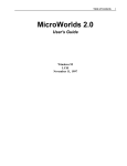
STR7 FAMILY
STR73x
Demonstration Software
USER MANUAL
Rev. 1
September 2005
1
USE IN LIFE SUPPORT DEVICES OR SYSTEMS MUST BE EXPRESSLY AUTHORIZED.
STMicroelectronics PRODUCTS ARE NOT AUTHORIZED FOR USE AS CRITICAL COMPONENTS IN
LIFE SUPPORT DEVICES OR SYSTEMS WITHOUT THE EXPRESS WRITTEN APPROVAL OF STMicroelectronics. As used herein:
1.Life support devices or systems are those which
(a) are intended for surgical implant into the body, or
(b) support or sustain life, and whose failure to perform, when properly used in accordance with instructions for use provided with the product, can be
reasonably expected to result in significant injury to
the user.
1
2. A critical component is any component of a life
support device or system whose failure to perform can reasonably be expected to cause the
failure of the life support device or system, or to
affect its safety or effectiveness.
STR73x Demonstration Software
USER MANUAL
1 INTRODUCTION
This document describes the demonstration software running on the STR73x-EVAL evaluation board, which you can be used to evaluate the capabilities of the microcontroller and the
on-board peripherals.
The demonstration software contains a main application divided into various smaller applications. It is already stored in the embedded flash memory of the microcontroller on the evaluation board. You can also download it from http://www.st.com/mcu and program it in the
STR73x flash.
Rev.1
3/31
Table of Contents
1 INTRODUCTION . . . . . . . . . . . . . . . . . . . . . . . . . . . . . . . . . . . . . . . . . . . . . . . . . . . . . . 3
2 FUNCTIONAL DESCRIPTION . . . . . . . . . . . . . . . . . . . . . . . . . . . . . . . . . . . . . . . . . . . 6
2.1
2.2
2.3
2.4
2.5
2.6
POWER CONTROL . . . . . . . . . . . . . . . . . . . . . . . . . . . . . . . . . . . . . . . . . . . . . . . 7
CLOCKING . . . . . . . . . . . . . . . . . . . . . . . . . . . . . . . . . . . . . . . . . . . . . . . . . . . . . 7
RESET CONTROL . . . . . . . . . . . . . . . . . . . . . . . . . . . . . . . . . . . . . . . . . . . . . . . 7
DEBUG JTAG INTERFACE . . . . . . . . . . . . . . . . . . . . . . . . . . . . . . . . . . . . . . . . 7
PROTOTYPE AREA . . . . . . . . . . . . . . . . . . . . . . . . . . . . . . . . . . . . . . . . . . . . . . 7
DISPLAYS . . . . . . . . . . . . . . . . . . . . . . . . . . . . . . . . . . . . . . . . . . . . . . . . . . . . . . 7
2.6.1 LCD . . . . . . . . . . . . . . . . . . . . . . . . . . . . . . . . . . . . . . . . . . . . . . . . . . . . . . . 7
2.6.2 LED . . . . . . . . . . . . . . . . . . . . . . . . . . . . . . . . . . . . . . . . . . . . . . . . . . . . . . . 7
2.7 INTERFACES . . . . . . . . . . . . . . . . . . . . . . . . . . . . . . . . . . . . . . . . . . . . . . . . . . . 8
2.7.1 RS232 . . . . . . . . . . . . . . . . . . . . . . . . . . . . . . . . . . . . . . . . . . . . . . . . . . . . . 8
2.7.2 CAN . . . . . . . . . . . . . . . . . . . . . . . . . . . . . . . . . . . . . . . . . . . . . . . . . . . . . . . 8
2.8 SERIAL EEPROM . . . . . . . . . . . . . . . . . . . . . . . . . . . . . . . . . . . . . . . . . . . . . . . . 8
2.9 MISCELLANEOUS PERIPHERALS . . . . . . . . . . . . . . . . . . . . . . . . . . . . . . . . . . 8
2.9.1 10-bit Analog to digital converter . . . . . . . . . . . . . . . . . . . . . . . . . . . . . . . . . 8
2.9.2 Push buttons . . . . . . . . . . . . . . . . . . . . . . . . . . . . . . . . . . . . . . . . . . . . . . . . 8
2.9.3 Buzzer . . . . . . . . . . . . . . . . . . . . . . . . . . . . . . . . . . . . . . . . . . . . . . . . . . . . . 8
3 RUNNING THE DEMONSTRATIONS . . . . . . . . . . . . . . . . . . . . . . . . . . . . . . . . . . . . . 9
3.1 MENU . . . . . . . . . . . . . . . . . . . . . . . . . . . . . . . . . . . . . . . . . . . . . . . . . . . . . . . . . 9
3.1.1 Welcome screen . . . . . . . . . . . . . . . . . . . . . . . . . . . . . . . . . . . . . . . . . . . . 10
3.1.2 Navigation . . . . . . . . . . . . . . . . . . . . . . . . . . . . . . . . . . . . . . . . . . . . . . . . . 10
3.2 CLOCK SOURCES . . . . . . . . . . . . . . . . . . . . . . . . . . . . . . . . . . . . . . . . . . . . . . 11
3.3 APPLICATION . . . . . . . . . . . . . . . . . . . . . . . . . . . . . . . . . . . . . . . . . . . . . . . . . . 12
3.3.1 Time Settings . . . . . . . . . . . . . . . . . . . . . . . . . . . . . . . . . . . . . . . . . . . . . . . 12
3.3.1.1 Time . . . . . . . . . . . . . . . . . . . . . . . . . . . . . . . . . . . . . . . . . . . . . . . 13
3.3.1.2 Date . . . . . . . . . . . . . . . . . . . . . . . . . . . . . . . . . . . . . . . . . . . . . . . 14
3.3.1.3 Alarm . . . . . . . . . . . . . . . . . . . . . . . . . . . . . . . . . . . . . . . . . . . . . . 14
3.3.2 Low-power modes . . . . . . . . . . . . . . . . . . . . . . . . . . . . . . . . . . . . . . . . . . . 15
3.3.2.1 STOP . . . . . . . . . . . . . . . . . . . . . . . . . . . . . . . . . . . . . . . . . . . . . . 16
3.3.2.2 HALT . . . . . . . . . . . . . . . . . . . . . . . . . . . . . . . . . . . . . . . . . . . . . . 17
3.3.2.3 Run . . . . . . . . . . . . . . . . . . . . . . . . . . . . . . . . . . . . . . . . . . . . . . . . 18
3.3.3 Temperature . . . . . . . . . . . . . . . . . . . . . . . . . . . . . . . . . . . . . . . . . . . . . . . 18
3.3.3.1 Celsius Unit . . . . . . . . . . . . . . . . . . . . . . . . . . . . . . . . . . . . . . . . . 19
3.3.3.2 Fahrenheit Unit . . . . . . . . . . . . . . . . . . . . . . . . . . . . . . . . . . . . . . . 19
3.3.4 Melodies . . . . . . . . . . . . . . . . . . . . . . . . . . . . . . . . . . . . . . . . . . . . . . . . . . 19
3.3.4.1 Single Mode . . . . . . . . . . . . . . . . . . . . . . . . . . . . . . . . . . . . . .31
. . . 20
3.3.4.2 Single Repeat Mode . . . . . . . . . . . . . . . . . . . . . . . . . . . . . . . . . . . 21
3.3.5 Period Measure . . . . . . . . . . . . . . . . . . . . . . . . . . . . . . . . . . . . . . . . . . . . . 21
4/31
1
INTRODUCTION
3.3.6 Board test . . . . . . . . . . . . . . . . . . . . . . . . . . . . . . . . . . . . . . . . . . . . . . . . . 22
3.3.6.1 Start Test . . . . . . . . . . . . . . . . . . . . . . . . . . . . . . . . . . . . . . . . . . . 23
3.3.6.2 Test Report . . . . . . . . . . . . . . . . . . . . . . . . . . . . . . . . . . . . . . . . . 26
3.3.7 Screen Saver . . . . . . . . . . . . . . . . . . . . . . . . . . . . . . . . . . . . . . . . . . . . . . . 27
3.4 SOFTWARE ARCHITECTURE . . . . . . . . . . . . . . . . . . . . . . . . . . . . . . . . . . . . . 28
5/31
FUNCTIONAL DESCRIPTION
2 FUNCTIONAL DESCRIPTION
The STR73x microcontroller evaluation board provides a development and demonstration
platform for STR73x-based applications. It is designed to allow you to try out the major functions of the STR73x microcontroller.
The following picture summarizes the main functional blocks of the evaluation board:
Figure 1. Evaluation board overview
STR73x
SPI SERIAL FLASH
I2C EEPROM
BUZZER
BSPI
UART1
RS232
I2C
UART2
RS232
CAN
CAN
GPIOs / TIM
16*2 LCD
LM35 SENSOR
ADC
PUSH BUTTONS
VARISTOR
GPIO
WAKE-UP BUTTON
BOOT
WIU
LEDs
BICOLOR LED
POWER CONTROL
RESET CONTROL
6/31
1
JTAG
IN-CIRCUIT EMULATOR
FUNCTIONAL DESCRIPTION
2.1 POWER CONTROL
The STR73x microcontroller family is powered by an external supply 5V (VDD = AVDD: 4.5 to
5.5V). All I/Os are 5V-capable.
The evaluation board is powered by an external 5V supply.
2.2 CLOCKING
The STR73x internal clocks are derived from two sources:
– Clocking is provided by a mounted 8 MHz external quartz.
– On-chip RC Oscillator (Backup oscillator) : ~2 MHz or ~32 KHz
2.3 RESET CONTROL
The Reset can be generated by hardware or software sources:
– Reset button: activates the RESET input when pressed.
– A JTAG reset
– A software reset
2.4 DEBUG JTAG INTERFACE
Software debug is done via the standard ARM JTAG connection: 20 pins IDC to connect to the
standard ARM host interface.
2.5 PROTOTYPE AREA
A 2.54*2.54 mm gridded area of 1mm holes is available for prototyping using wire wrap or similar prototyping techniques
2.6 DISPLAYS
2.6.1 LCD
16 characters * 2 lines LCD display connected to GPIOs.
2.6.2 LED
– Red LEDs: Connected to 16 General Purpose Input Output pins.
– Bicolor LED: Connected to 6 General Purpose Input Output pins.
– SMD LED: Showing the status of the Power 5V.
7/31
FUNCTIONAL DESCRIPTION
2.7 INTERFACES
2.7.1 RS232
The STR73x evaluation board (STR73x-EVAL) provides two on-board RS-232 serial ports
that are driven directly by the Two embedded UART.
Both these RS232 ports are terminated by DB9 connectors.
2.7.2 CAN
The STR730 CAN manages a single DB9 connector with two switch-selectable low speed
(L9669) or high speed (L9615 or L9616) transceivers.
2.8 SERIAL EEPROM
– I2C EEPROM : 8-Kbit connected to the I2C0 interface
– SPI EEPROM : 8-Kbit connected to the buffered serial peripheral interface BSPI2
2.9 MISCELLANEOUS PERIPHERALS
2.9.1 10-bit Analog to digital converter
– Varistor: ADC channel0 connected to an on board variable resistor. The variable resistor
provides a voltage in the range of 0 to 5V.
– LM35 sensor: ADC channel1 is connected to the LM35 output voltage.
2.9.2 Push buttons
The following push buttons are provided:
– NEXT: programmable switch
– PREV: programmable switch
– SEL: programmable switch
– BACK: programmable switch
– RST: board reset
– WAKE-UP: push-button to wake-up the processor from low power modes
2.9.3 Buzzer
– Piezo buzzer: OCPMA0 or OCPMA1 can be connected to the on-board piezo buzzer through
switcher SW10.
8/31
RUNNING THE DEMONSTRATIONS
3 RUNNING THE DEMONSTRATIONS
3.1 MENU
Figure 2. Structure of the Demonstration Menus
Welcome screen "WELCOME TO THE STR730 DEMO"
Time Setting
Time
Adjust
Show
Date
Adjust
Show
Alarm
Adjust
Show
Low PR modes
STOP
Exit by Pin
Exit by WUT
HALT
RUN
32 MHz
16 MHz
8 MHz
4 MHz
Celsius Unit
Temperature
Fahrenheit Unit
Melodies
Single
Melody1
Melody2
Melody3
Single
Repeat
Melody1
Melody2
Period Measure
Board Test
Melody3
Start Test
Test Report
9/31
RUNNING THE DEMONSTRATIONS
The above figure shows the menu system of the STR73x demonstration. The column to the
left displays the main menu. "NEXT" and "PREV" push-buttons allow you to navigate between
the items in the menu. To enter a sub-menu, press the "SEL" push-button. To exit a sub-menu
press the "BACK" push-button.
3.1.1 Welcome screen
The following table summarizes which peripherals are used in this part of the software:
Table 1. Peripherals used by Welcome screen software
STR730 peripheral used
GPIOs
EIC
Purpose
NEXT/PREV/SEL/BACK button (Pin configuration)
Driving the LCD
NEXT/PREV/SEL/BACK buttons (navigating through the menus)
After a board RESET, a scrolling message appears on the LCD: “WELCOME TO THE
STR730 DEMO“ as shown in the figure below.
WELCOME TO THE
STR730 DEMO
Then the application enters in the main menu and displays the first menu item "Time Set-
tings".
Note: When the board is powered up for the first time, you have to set the date and time in the
"Time Settings" menu.
3.1.2 Navigation
The demonstration menu is based on circular navigation, sub-menu, item selection and back
capability as follows:
10/31
RUNNING THE DEMONSTRATIONS
Figure 3. Navigating in the demonstration menus
st
WELCOME SCREEN 1 LEVEL
2nd LEVEL
NEXT
NEXT
item 1
NEXT
SEL
NEXT
PREV
NEXT
Back
item 2
PREV
SEL
...
PREV
item 1.2
NEXT
PREV
...
L
SE
...
item n
item 1.1
item n-1
item n-1
item 2.1
Back
NEXT
SEL
...
PREV
item 2.2
NEXT
PREV
...
item n-1
The user navigates using the “NEXT”, “PREV” ,“SEL” and “BACK” push buttons located on
the evaluation board.
– “NEXT” and “PREV” buttons perform circular navigation in the current menu items
– “SEL” button selects the current item
– “BACK” jumps to the higher level menu.
When the demonstration menu is activated, the following message is displayed on the LCD
previous level
menu item
3.2 CLOCK SOURCES
The STR730 internal clocks are derived from two sources: mounted 8 MHz quartz and an onchip RC Oscillator (2 MHz or 32 kHz).
11/31
RUNNING THE DEMONSTRATIONS
In this demo application, the MCLK frequency is set to 32 MHz and the external clock frequency EXTCLK is set to 31,25kHz in normal running mode. Some peripherals such as TB0,
TB1, TB2, WDG and RTC are clocked by the EXTCLK.
The MCLK clock can be changed only in the "Run" sub-menu: it can be 32 MHz, 16 MHz, 8
MHz or 4 MHz.
Figure 4. Clock Control
Crystal 8 MHz
1/256
EXTCLK = 31.25kHz
RTCP
CK2_16
1/16
CSU_CKSEL
DIV2
CMU
0
1/2
1
PLL
*
6/8/10/14
0
1/1, 1/2...1/7
DX(2:0)
RC Oscillator
2 MHz
MX(1:0)
1
0 MCLK = 32 MHz
1
or
MCLK = 16 MHz
MCLK = 8 MHz
MCLK = 4 MHz
3.3 APPLICATION
The following section provides a detailed description of each part of the demonstration.
Notes:
– In the demonstration, the core runs at MCLK=32 MHz.
– The external clock is set to EXTCLK=31.25 kHz
– Red LEDs connected to GPIO4 are always blinking with a frequency depending on the core
clock.
– Bicolor LEDs connected to the GPIO2 switch continuously from red to green with a frequency
depending on the core clock.
3.3.1 Time Settings
The STR730 provides a Real Time Clock (RTC) which provide a set of continuously running
counters that can be used, with suitable software, to implement a clock-calendar function. The
counters values can be written to set the current time of the system.
12/31
RUNNING THE DEMONSTRATIONS
This sub-menu is used to configure some miscellaneous functions such as time, date and
alarm.
Table 2. Peripherals used by Time Settings software
STR730 peripheral used
GPIOs
TIM2
PWM0..5
PWM1
EIC
RTC
TIM1
TB2
ADC
I2C
Purpose
NEXT/PREV/SEL/BACK button (Pin configuration)
Driving the LCD
GPIO4 blinking red LEDs
P3.0 ADC channel0
GPIO4 delay for blinking red LEDs
GPIO2 blinking bicolor LEDs
GPIO2 delay for blinking bicolor LEDs
NEXT/PREV/SEL/BACK buttons (navigating through the menus)
GPIO2 delay for blinking bicolor LEDs: PWM1
GPIO4 delay for blinking red LEDs: TIM2
Setting the time, date and alarm
Generate the alarm notes frequencies
Count the alarm notes duration
Adjust sound volume using potentiometer
Read Alarm melody data from I2C EEPROM
3.3.1.1 Time
This sub-menu is divided in two items allowing the user to display or to adjust the current time.
– Adjust: After the evaluation board is powered up the user has to select this sub-menu to
change the default time (00:00:00) to the current time. Once "Adjust" is selected, the first
digit of the hour field is ready to be changed. Pressing the "NEXT" button will display the
current value plus one. Pressing the "PREV" button will display the previous digit value. To
change the digit value, press "NEXT" or "PREV". After choosing the digit value press SEL,
the cursor jumps automatically to the next digit. When all the time digits are set, you need to
press the "BACK" button to exit from the "Time Adjust" sub menu. Some digit values are limited to a range of values depending on the field (hour, minute or seconds). The following
message (with the default time or the current time) is displayed on the LCD when this submenu is selected:
Time Adjust
HH:MM:SS
13/31
RUNNING THE DEMONSTRATIONS
– Show: this item displays the current time or the default time. The following message is displayed on the LCD when this sub-menu is selected:
Time Show
HH:MM:SS
3.3.1.2 Date
This sub-menu is divided in two items allowing the user to display or to adjust the current date.
– Adjust: This item has to be selected after each power-up in order to set the current date.
The user is asked to fill the current date to be stored in the application memory. The date is
displayed on 8 digits: MM/DD/YYYY. The date value 01/01/2005 is displayed when you enter
this menu for the first time after power-up. The first digit of the month field is ready to be
changed. To change the digit value it is needed to press "NEXT" or "PREV". Pressing
"NEXT" button will display the current value plus one, pressing "PREV" button will display
the previous value. After choosing the digit value press "SEL", the cursor jumps automatically to the next digit. When all the date digits are set, press the "BACK" button to exit from
the "Date Adjust" sub menu. Some digits values are limited depending on the field (month,
day or year). In case of a re-adjust of the date, the current date value is shown. The following
message is displayed on the LCD when this sub-menu is selected:
Date Adjust
01/01/2005
– Show: this item displays the current date. The default date displayed after power up and before using the Adjust item application is 01/01/2005. The following message is displayed on
the LCD when this sub-menu is selected:
Date Show
MM/DD/YYYY
3.3.1.3 Alarm
By means of this Sub-menu the user can configure the time when an alarm can be activated.
When the alarm time value is reached the alarm sound is generated in addition of sequence of
14/31
RUNNING THE DEMONSTRATIONS
LED blinking. The Alarm melody is loaded in the I2C EEPROM at the start of the demonstartion then it is read and played when an alarm occurs. The alarm volume can be adjusted
using the potentiometer. This sub-menu is divided in two items to display or to adjust the current Alarm.
– Adjust: the alarm adjust is reached by the same procedure as the Time Adjust Submenu.
Alarm Adjust
HH:MM:SS
– Show: this item displays the current alarm time. The default Alarm displayed after power up
and before using the Adjust item application is 00:00:00. The following message is displayed
on the LCD when this sub-menu is selected:
Alarm Show
HH:MM:SS
3.3.2 Low-power modes
The STR730 microcontroller provides different operating modes in which the power consumption is reduced. The purpose of this menu is to show the behaviour of the microcontroller in different low-power modes. STOP and HALT mode are taken as examples.
15/31
RUNNING THE DEMONSTRATIONS
Figure 5. Peripherals used by Low Power modes software
STR730 peripheral used
GPIOs
TIM2
PWM0..5
PWM1
EIC
WIU
WUT
PRCCU
CMU
Purpose
NEXT/PREV/SEL/BACK button (Pin configuration)
Driving the LCD
GPIO4 blinking red LEDs
GPIO4 delay for blinking red LEDs
GPIO2 blinking bicolor LEDs
GPIO2 delay for blinking bicolor LEDs
NEXT/PREV/SEL/BACK buttons (navigating through menus)
GPIO2 bicolor LEDs blinking delay: PWM1
GPIO4 red LEDs blinking delay: TIM2
Interrupt when the WAKE-UP push-button is pressed: WIU
Entering STOP mode
Wake-up the system from STOP mode (external interrupt)
Wake-up the system from STOP mode (end of timer count)
Clock setting
Clock monitoring
3.3.2.1 STOP
This menu allows you to put the STR730 in STOP mode. The software performs the specific
sequence of instructions needed to enter STOP mode. STOP mode is characterized by:
* Possibility to turn off the RC Oscillator
* Main Oscillator turned off (if RTC module is not running)
* Minimum power consumption
* Automatic context saving
In this application, there are two ways to make the STR730 exit from STOP mode:
– In the first one, the WAKE-UP push button (connected to Wake-up line16) is used to exit
the MCU from STOP mode. The following message is displayed on the LCD:
STOP Mode
exit by pin
The red LEDs continue blinking until the "SEL" push button is pressed, then the system enters
STOP mode and the following message is displayed on the LCD:
16/31
RUNNING THE DEMONSTRATIONS
STOP Mode
WAKE-UP: exit
The MCU will remain in STOP mode unless the WAKE-UP push button is pressed. Once this
button is pressed, the MCU exits from STOP mode. Then the system clock is set to 32 MHz
and the application continues its execution.
– In the second case, the Wake Up Timer (WUT) will wake-up the MCU from STOP mode
after 10 seconds. The following message is displayed on the LCD:
STOP Mode
exit by WUT
The red LEDs continue blinking until the "SEL" push button is pressed, then the system enters
STOP mode and the following message is displayed on the LCD:
STOP Mode
Wakeup in 10s
After 10 seconds have elapsed, the system exits from the STOP mode. Then the system
clock is set to 32 MHz and the application continues its execution.
3.3.2.2 HALT
This menu allows you to put the STR730 in HALT mode. The software performs the specific
sequence of instructions needed to enter HALT mode. HALT mode is characterized by:
* RC Oscillator turned off
* Main Oscillator turned off (if RTC module is not running)
* Minimum power consumption
Exit from HALT mode is possible only by means of an external or LVD reset.
17/31
RUNNING THE DEMONSTRATIONS
The following message is displayed on the LCD:
HALT Mode
RST: exit
3.3.2.3 Run
STR730 provides a Power, Reset and Clock Configuration Unit (PRCCU) and a Clock Monitor
Unit (CMU) which allows the user to configure the system clock.
Selecting this item shows how an application can be run at different clocking frequencies.
Blinking LEDs show the effect of changing the clock.
The following message is displayed on the LCD:
RUN Mode
32 MHz
The RUN menu contains five submenu items:
– "32 MHz": the application runs at 32 MHz.
– "16 MHz": the application runs at 16 MHz.
– "8 MHz": the application runs at 8 MHz.
– "4 MHz": the application runs at 4 MHz.
The user has to press the "SEL" push button to select one of the listed run modes. "BACK"
button has to be pushed to exit from any selected mode and return to 32 MHz as default clock
value.
3.3.3 Temperature
This menu allows you to display the ambiant temperature. The STR730 microcontroller provides a 10-bit Analog to Digital Converter (ADC), with +/-2 LSB maximum error and an input
range of 0 to 5V.
Reading the LM35 output voltage through the ADC channel1, the ambiant temperature can be
measured in the range: 0°C to 150°C.
18/31
RUNNING THE DEMONSTRATIONS
Figure 6. Peripherals used by Temperature software
STR730 peripheral used
Purpose
NEXT/PREV/SEL/BACK button (Pin configuration)
Driving the LCD
GPIO4 blinking red LEDs
P3.1 ADC channel1
GPIO4 delay for blinking red LEDs
GPIO2 blinking bicolor LEDs
GPIO2 delay for blinking bicolor LEDs
NEXT/PREV/SEL/BACK buttons (navigating through the menus)
GPIO2 bicolor LEDs blinking delay: PWM1
GPIO4 red LEDs blinking delay: TIM2
Read ADC converted result on channel1: ADC
Convert the LM35 output signal on channel1
GPIOs
TIM2
PWM0..5
PWM1
EIC
ADC
The user is asked to choose the temperature unit (°C or °F), this sub-menu contains two items:
3.3.3.1 Celsius Unit
When you select this sub-menu the temperature is displayed in Celsius. The temperature
value changes at each end of conversion (EOC) of the ADC and is then updated on the LCD.
The following message is displayed on the LCD:
Temperature
xx.x °C
3.3.3.2 Fahrenheit Unit
When you select this sub-menu the temperature is displayed in Fahrenheit. The temperature
value changes at each end of conversion (EOC) of the ADC and is then updated on the LCD.
The following message is displayed on the LCD:
Temperature
xxx.x °F
3.3.4 Melodies
The STR730 microcontroller provides Timers and PWMs modules which can be used for
timing purposes and generating the output signals. In this case, we use an standard Timer
(TIM) and a Time Base timer (TB) to generate a PWM signal with a tunable frequency and
19/31
RUNNING THE DEMONSTRATIONS
duty cycle which, with an external piezo buzzer, allow you to generate musical notes. There
are three melody buffers which are loaded in the BSPI EEPROM when the demonstration
starts. When a melody is selected, its corresponding buffer is automatically read from the
BSPI EEPROM and then used to generate notes.
Switch SW10, has to be set in position 1-2 to connect the buzzer to the TIM1 Output Compare
A (OCMPA).
Table 3. Peripherals used by Melodies software
STR730 peripheral used
GPIOs
TIM2
PWM0..5
PWM1
EIC
TIM1
TB0
ADC
DMA
BSPI
Purpose
NEXT/PREV/SEL/BACK button (Pin configuration)
Driving the LCD
GPIO4 blinking red LEDs
P3.0 ADC channel0
P1.7 TIM1 Output Compare A
GPIO4 delay for blinking red LEDs
GPIO2 blinking bicolor LEDs
GPIO2 delay for blinking bicolor LEDs
NEXT/PREV/SEL/BACK buttons (navigating through the menus)
GPIO2 bicolor LEDs blinking delay: PWM1
GPIO4 red LEDs blinking delay: TIM2
End of TB0 count
Generate the note frequency: used in PWM mode
Count the note duration
Adjust sound volume using potentiometer
Transfer data from BSPI receive FIFO
Read melody data from SPI EEPROM
You can play a melody only once by selecting "single mode" or play it continuously by selecting "single repeat" mode. The volume can be adjusted using the potentiometer connected
to ADC channel0.
3.3.4.1 Single Mode
In this sub-menu the selected melody is played only once. The melody can be stopped when
the "BACK" push button is pressed.
– "Melody 1": When selected, it plays melody 1.
– "Melody 2": When selected, it plays melody 2.
– "Melody 3": When selected, it plays melody 3.
20/31
RUNNING THE DEMONSTRATIONS
The following message is displayed on the LCD:
Single
MelodyX
3.3.4.2 Single Repeat Mode
In this sub-menu the selected melody is played in a continuous mode till the "BACK" push
button is pressed.
– "Melody 1": When selected, it plays melody 1.
– "Melody 2": When selected, it plays melody 2.
– "Melody 3": When selected, it plays melody 3.
The following message is displayed on the LCD:
Single Repeat
MelodyX
3.3.5 Period Measure
This menu allows you to measure the period of an input signal. The STR730 TIM timers can
be used in PWM input mode to measure the frequency and the duty cycle of an input signal in
a range which depends on the TIMx clock: in our case the range is from 488 Hz to 10 kHz. You
have to connect the signal to be measured to the ICAPA4/P1.3 pin.
Table 4. Peripherals used by the Period Measure software
STR730 peripheral used
GPIOs
TIM2
PWM0..5
PWM1
EIC
TIM4
TB1
Purpose
NEXT/PREV/SEL/BACK button (Pin configuration)
Driving the LCD
GPIO4 blinking red LEDs
P1.3 TIM4 input capture A
GPIO4 delay for blinking red LEDs
GPIO2 blinking bicolor LEDs
GPIO2 delay for bicolor LEDs
NEXT/PREV/SEL/BACK buttons (navigating through the menus)
GPIO2 delay for blinking bicolor LEDs: PWM1
GPIO4 delay for blinking red LEDs: TIM2
End of TB1 count
Measure the frequency and duty cycle of the input signal
Display the frequency and duty cycle values periodically (300ms)
21/31
RUNNING THE DEMONSTRATIONS
If the input signal is in the specified range, the following message is displayed on the LCD:
duty cycle: xx%
freq: xxxxx Hz
If the signal is under the low limit of the range, the following message is displayed on the LCD:
out of range!!
freq < 488 Hz
If the signal is over the high limit of the range, the following message is displayed on the LCD:
out of range!!
freq > 10 kHz
If there is no signal connected to the ICAPA4/P1.3 pin, the following message is displayed on
the LCD:
!!no signal!!
3.3.6 Board test
This test consists of checking the different components of the board and the STR730 peripherals.
Table 5. Peripherals are used by the Board test software:
STR730 peripheral used
GPIOs
22/31
Purpose
NEXT/PREV/SEL/BACK button (Pin configuration)
Driving the LCD
GPIO4 blinking red LEDs
GPIO2 blinking bicolor LEDs
Generate sound using buzzer
RUNNING THE DEMONSTRATIONS
STR730 peripheral used
Purpose
GPIO4 red LEDs lighting select using potentiometer
Temperature measurement
Write/Read on I2C EEPROM
Write/Read on BSPI EEPROM
UART test board
UART test board
ADC
I2C
BSPI
UART0
UART1
The board test is made of the following sub-menus:
3.3.6.1 Start Test
You select this sub-menu to start the various board tests.
After each test the user is asked to store the test result. Press the "SEL" push button if the test
is passed, else press the "BACK" push button if test has failed.
These tests are:
– PushButtons Test: tests all the connected push buttons which are "SEL", "BACK", "WAKEUP", "NEXT" and "PREV". The following message is displayed on the LCD:
PushButtons Test
Press ^xxxx^
– Red LEDs test: Successively lights up the red LEDs connected to GPIO4. The following message is displayed on the LCD:
Red Leds Test
Press ^Next^
Press "NEXT" to select whether the current test is passed or failed.
Press "SEL" when the test is passed else press "BACK".
23/31
RUNNING THE DEMONSTRATIONS
– PWM LEDs test: Successively lights up the bicolor LEDs connected to GPIO2. The following
message is displayed on the LCD:
PWM Leds Test
Press ^Next^
Press "NEXT" to select whether the current test is passed or failed.
Press "SEL" when the test is passed else press "BACK".
– LM35 test: tests if the temperature sensor works correctly and displays the temperature value in Fahrenheit. The following message is displayed on the LCD:
LM35 Test
xx.x °F /^Next^
Press "NEXT" to select whether the current test is passed or failed.
Press "SEL" when the test is passed else press "BACK".
– Varistor test: tests whether the potentiometer connected to Channel0 of the ADC works correctly. The number of the red LEDs turned on corresponds to the potentiometer output voltage. The following message is displayed on the LCD:
Var Resist Test
Press ^Next^
Press "NEXT" to select whether the current test is passed or failed.
Press "SEL" when the test is passed else press "BACK".
– Buzzer test: tests whether the buzzer works correctly on both positions of switch SW10. For
the first test, switch SW10 has to be in 1-2 position.
24/31
RUNNING THE DEMONSTRATIONS
The following message is displayed on the LCD:
Buzzer SW10:1-2
Press ^Next^
Press "NEXT" to display whether the current test is passed or failed.
Press "SEL" when the test is passed else press "BACK". Then change switch SW10 to position 2-3.
Buzzer SW10:2-3
Press ^Next^
Press "NEXT" to display whether the current test is passed or failed.
Press "SEL" when the test is passed else press "BACK".
– I2C test: Testing Write/ Read operations on I2C EEPROM.
Once the test is finished, a message is displayed indicating whether the I2C test is passed or
failed.
Then, the following message is displayed on the LCD:
I2C Test
Press ^Next^
Press "NEXT" to start the next test.
– BSPI test: Testing Write/ Read operations on SPI EEPROM.
Once the test is finished, a message is displayed indicating whether the BSPI test is passed or
failed.
25/31
RUNNING THE DEMONSTRATIONS
Then, the following message is displayed on the LCD:
BSPI Test
Press ^Next^
Press "NEXT" to start the next test.
– UART test: Testing a transmission and reception between UART0 and UART1. For this test
you have to connect a null-modem female/female RS232 cable between the two DB9 connectors on the evaluation board (CN2-CN3).
Once the test is finished, a message is displayed indicating whether the UART test is passed
or failed.
The following message is displayed on the LCD:
UART Test
Press ^Next^
Press "NEXT" to exit the board test sub-menu.
3.3.6.2 Test Report
This sub-menu offers the possibility of showing the result of all tests done in the "Start Test"
sub-menu.
If you select this sub-menu before starting the test, the following message is displayed twice
on the LCD:
Board test not
done yet!!!!
26/31
RUNNING THE DEMONSTRATIONS
After selecting this sub-menu, the result of all the board tests is displayed, it is failed if at least
one test was not correct, else passed if all tests are done successfully. The following message
is displayed on the LCD:
Overall test
!!!xxxxxx!!!
Failed
Passed
If some tests were failed, a second message is displayed which contains in the first line the
number of the failed test, and in the second line the name of those tests which you can display
one-by-one using the "NEXT" and "PREV" push buttons. The following message is displayed
on the LCD:
Test number
Test name
xx Test failed
xxxx Test
see
next
tests using
"NEXT" and
"PREV"
To exit from the "Test Report" sub-menu, press the "BACK" push button.
3.3.7 Screen Saver
The STR730 Watchdog Timer module (WDG) can be used in Watchdog mode to reset the
system or can be used in Timer mode to generate an interrupt after a selected time delay depending on the system clock.
In this demonstration software the WDG module is enabled in Timer mode and generates an
End of Count interrupt, that sets a screen saver display when the WDG timer reaches a specified time delay. If none of the push-buttons are pressed during this delay which is 30 seconds,
the screen saver is displayed on the LCD. As soon as a push button is pressed, the last submenu is re-displayed on LCD.
The following table summarizes which peripherals are used in this software part:
STR730 peripheral used
GPIOs
TIM2
PWM0..5
PWM1
EIC
WDG
Purpose
NEXT/PREV/SEL/BACK button (Pin configuration)
Driving the LCD
GPIO4 red LEDs blinking
GPIO4 red LEDs blinking delay
GPIO2 bicolor LEDs blinking
GPIO2 bicolor LEDs blinking delay
GPIO2 bicolor LEDs blinking delay: PWM1
GPIO4 red LEDs blinking delay: TIM2
End of WDG Timer count
Count the 30 seconds and if enabled set the screen saver mode
27/31
RUNNING THE DEMONSTRATIONS
When the demonstrations enter in screen save mode, the date and time are displayed on the
LCD as shown in the figure below. The time and date are continuously updated:
DD/MM/YY
HH:MM:SS
Using the WDG functions, we are can enable or disable the screen saver for each demonstration sub-menu. It is disabled in five sub-menus which are: Time Adjust, Date Adjust, Alarm Adjust, Period Measure and Board test.
3.4 SOFTWARE ARCHITECTURE
This section describe the software architecture it is divided into two layers:
– Hardware library layer: contains the software library source files. These do not need to be
modified by the user:
* 73x_conf.h: the header file to configure which peripherals are used, and miscellaneous defines
* 73x_type.h: contains the common data types and enumerations used in the other files
* 73x_map.h: contains the peripheral memory mapping and register data structures
* 73x_lib.h: main header file including all the others
* 73x_it.h: contains the interrupt handler prototypes
* 73x_it.c: the source file containing the interrupt handlers
– Demonstration architecture: contains the architecture of the demonstration software that
may be modified by the user:
* menu.h: Header for the menu.c file.
* menu.c: This file provides a set of functions needed to manage the demonstration menu
* timesetting.h: Header for the timesetting.c file
* timesetting.c: This file provides functions for managing time, date and alarm events
* lowpower.h: Header for the lowpower.c file
* lowpower.c: This file provides low power modes functions
* periodmeasure.h: Header for the periodmeasure.c file
28/31
RUNNING THE DEMONSTRATIONS
* periodmeasure.c: This file provides functions for measuring the period and the duty cycle of
an external signal
* temperature.h: Header for the temperature.c file
* temperature.c: This file provides functions for displaying the temperature measured by the
LM35 sensor
* buzzer.h: Header for the buzzer.c file
* buzzer.c: This file provides functions for playing melodies
* leds.h: Header for the leds.c file
* leds.c: This file provides functions for managing red LEDs connected to GPIO4 and bicolor
LEDs connected GPIO2
* lcd.h: Header for the lcd.c file
* lcd.c: This file provides a set of functions needed to manage the LCD connected to P0.(0..10)
pins
* i2c_ee.h: Header for the i2c_ee.c file
* i2c_ee.c: This file provides a set of functions needed to manage the I2C M24C08 EEPROM
* spi_ee.h: Header for the spi_ee.c file
* spi_ee.c: This file provides a set of functions needed to manage the SPI M95080 EEPROM
* boardtest.h: Header for the boardtest.c file
* boardtest.c: This file provides functions for testing the STR73x-EVAL board.
* main.h: Header for the main.c file
* main.c: This file provides a set of functions needed to manage the demonstration menu
29/31
RUNNING THE DEMONSTRATIONS
Figure 7. Software Architecture
timesetting.c
periodmeasure.c
timesetting.h
boardtest.c
periodmeasure.h
boardtest.h
temperature.c
spi_ee.c
buzzer.c
led.c
temperature.h
spi_ee.h
buzzer.h
led.h
lowpower.c
i2c_ee.c
lowpower.h
i2c_ee.h
main.c
Menu.c
lcd.c
Menu.h
lcd.h
main.h
73x_it.c
User Application
73x_conf.h
Hardware Library
73x_map.h
ppp.h
xxx.h
ppp.c
xxx.c
73x_lib.h
30/31
ppp.h
ppp.c
73x_it.h
RUNNING THE DEMONSTRATIONS
THE SOFTWARE INCLUDED IN THIS MANUAL IS FOR GUIDANCE ONLY.
STMICROELECTRONICS SHALL NOT BE HELD LIABLE FOR ANY DIRECT, INDIRECT OR
CONSEQUENTIAL DAMAGES WITH RESPECT TO ANY CLAIMS ARISING FROM USE OF
THE SOFTWARE.
Information furnished is believed to be accurate and reliable. However, STMicroelectronics assumes no responsibility for the consequences
of use of such information nor for any infringement of patents or other rights of third parties which may result from its use. No license is granted
by implication or otherwise under any patent or patent rights of STMicroelectronics. Specifications mentioned in this publication are subject
to change without notice. This publication supersedes and replaces all information previously supplied. STMicroelectronics products are not
authorized for use as critical components in life support devices or systems without express written approval of STMicroelectronics.
The ST logo is a registered trademark of STMicroelectronics.
All other names are the property of their respective owners
© 2005 STMicroelectronics - All rights reserved
STMicroelectronics group of companies
Australia – Belgium - Brazil - Canada - China – Czech Republic - Finland - France - Germany - Hong Kong - India - Israel - Italy - Japan Malaysia - Malta - Morocco - Singapore - Spain - Sweden - Switzerland - United Kingdom - United States of America
www.st.com
31/31