1
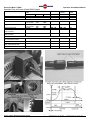
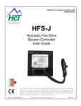
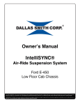
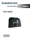
Reverse-A-Matic™ RM60
Operation & Installation Manual
Reverse-A-Matic™ RM60
Operation of the
Reverse-A-Matic ™
Backup Lights and Alarm System
Yellow Wire
The Reverse-A-Matic™ System (R-A-M) is a standalone trailer module designed to automatically control
the backup lights & alarm, to activate lift axles and
control steer axles. The Reverse-A-Matic™ module
and sensor are to be installed on a trailer.
Features
•
•
•
•
•
•
•
Senses trailer direction and speed.
Speed Sensitive steer axle control.
SPIF Infrastructure Friendly Compliant 2005/2006
Requires NO MANUAL CONTROL from the cab.
Emergency 4-Way Flasher lift control feature.
Activates after eight inches in reverse.
Bulb Check output for Enhanced Semi-Trailer
braking systems
When in reverse, it will
•
•
•
•
•
•
Turn on trailer backup lights.
Activate trailer backup alarm system.
Lift the trailer lift axle for ease of manoeuvring.
Secure a steer axle.
Can activate a dome light inside the trailer.
Can power a reverse radar system.
When travelling forward, it will
• Automatically lower a lift axle after 100 feet.
• Pulls out the trailer locking pin for free steering.
• Lock the steer axle above 60KPH for straight
operation on the Highway.
• Monitors 4-way flashers and speed to lift an axle
for emergency traction.
Model RM60 OUTPUTS
The Reverse-A-Matic RM60 has six outputs & two
inputs. All of the features of the original RM50 are
incorporated into the RM60.
Function
Colour
Bullets Connectors
12 Volt Input
Blue
Ground
White
Beeper
Yellow
Lift Axle Control.
Brown
SteerAxle Power to
Green
Lock
SteerAxle Power to
Black
Free
Sensor Connector
Sensor Interface
WeatherPack Connector
Bulb Check Feature
A – Red
Forward Lift Axle
B – Pink
4-Way Input
C – Grey
4-Way Input
D – Grey
Operator’s Manual
The backup lights and alarm will come on and remain
on whenever the trailer is moving in reverse. The
backup lights will turn off five seconds after the truck
has stopped, or if the truck has moved forward. Large
back-up flood lights can be controlled by the ReverseA-Matic. The Beeper output may be connected to an
external relay to supply enough current to the lights.
Lift Axle
Brown Wire
The Brown wire will activate the lift axle when the
trailer is reversing. The lift axle will remain up until
the truck has moved 100 feet forward without
stopping. Once the lift axle is down it shall remain
disengaged whenever travelling forward. The lift axle
will lower when power is disconnected from the
trailer or when the ignition is turned off.
Emergency 4-Way Flasher Forward Lift Axle
PINK Wire,
The Forward lift axle is the same function as the
Brown wire functions except it will also raise the axle
using the 4-way flashers. This feature is to transfer
weight for greater traction on the tractor tandem
axles. This will only happen when the 4-Way flashers
activation sequence is started. It will only lift the
forward axle while the 4-way are ON & the speed is
under 60 Km/H. If the trailer goes above 60 Km/H
then the axle will lower and the activation sequence
must be repeated. The PINK wire will lift the forward
axle with the 4-Ways, the Brown wire will not.
Emergency 4-Way Flasher Activation
ON-OFF-ON (3 Seconds each)
In/Out
Input
Output
Output
Output
Output
Input
Output
Output
Input
Input
To operate the forward lift axle, the 4-Way flashers
must be turned ON for 3 seconds or more, then
turned OFF for about 3 seconds, then turned ON
again. The axle will remain up until the 4-Way
flashers are turned OFF or if the trailer goes above 60
Km/H. This double activation sequence prevents
unintentional or accidental lifting of the axle if the 4Way flashers are turned ON for other reasons. This
Forward Lift Axle function is designed to meet SPIF
regulations for emergency drive traction.
Steer Axles
The operation of Steer axles are to follow the road
freely. Most steer axles have a locking pin that needs
to be inserted to lock the axle and hold it for straight
operation. The axle may be lifted or locked when
reversing. The Reverse-A-Matic will lock the axle in
reverse so that it does not track sideways. Steer axles
can be controlled in two ways, Normally Locked and
Normally Free. The Reverse-A-Matic RM60 provides
an output for each method.
1. Normally Locked (Power to Free)
BLACK Wire
A Normally Locked Steer axle will have the locking
pin inserted by a spring or mechanical force. It will
be locked if the trailer has no power or no air. This
requires Power to Free the axle
The Black Wire is Power to Free and will provide
+12 volts out to the locking pin control solenoid to
pull the pin and free to steer the axle when the
trailer is going forward less than 60 KPH. It will be
zero volts in reverse and forward faster than 60
KPH so that the axle will be locked.
Reverse-a-Matic™ Wheel Direction Sensor System
1
2. Normally Free. (Power to Lock)
GREEN Wire
A Normally Free Steer axle will have the locking pin
pulled out by a spring or mechanical force. It will
be free to steer if the trailer has no power or no
air. This requires Power to Lock the axle
The Green Wire is Power to Lock and will provide
+12 volts out to the locking pin control solenoid to
insert the pin and lock the axle when the trailer is
in reverse or when it is travelling forward faster
than 60 KPH. It will be zero volts when going
forward less than 60 KPH so that the axle will be
free to steer.
If the wiring or unit ever fails or if there is no power
or no air on the trailer, then the axle will be in its
normal condition. This is a safety feature of the
Reverse-A-Matic RM60 and is the reason that there
are two outputs.
6 Second Delay for Steer PinLock
Steer axles may be liftable. If so, the lift axle output
should be used to lift them. The steer axle control is
for the locking pin only. There is a 6 second delay in
locking the Steer axle in reverse. This allows the axle
to lift first and straighten out before the pin is
inserted.
Immediate locking of a steer axle cannot guarantee
straight operation in reverse because the tires may
not be straight when the trailer starts to back up.
Other arrangements can be made if needed.
STEER AXLE LOCKING SPEED
The Reverse-A-Matic model RM60 will lock the steer
axle in reverse and on the Highway. The speed is
determined by the wheels on the trailer. The size of
the tire will effect the speed at which the steer axle
will lock. Please check the chart below for estimated
threshold speeds. These are +/-3%.
The Reverse-A-Matic uses a speed threshold, it will
be locked above the Lock-Up speed and Unlocked
below the Unlock Speed.
The Reverse-A-Matic also use a distance threshold,
this is to reduce frequent locking and unlocking of the
pin. It will unlock quickly when slowing down because
a trailer can brake faster than it can accelerate.
Tire Diameter Versus Speed
Conversion Chart
Tire
Lock-Up
Unlock
Diameter
Speed
Speed
(Inches)
KPH
KPH
39.0
39.5
40.0
55.8
56.5
57.2
51.5
52.2
52.9
40.5
57.9
53.5
41.0
41.5
42.0
42.5
43.0
43.5
44.0
58.7
59.4
60.1
60.8
61.5
62.2
62.9
54.2
54.8
55.5
56.2
56.8
57.5
58.2
SPIF Regulations
Please check regulations in ONTARIO REG. 413/05
and steer axle controls to ensure that the Reverse-AMatic installation and your trailer configuration meets
all codes. Not every installation will require all of the
functions of the Reverse-A-Matic RM60
Preliminary Copy – Jan 12 2006,
© 2006 Wheel Monitor Inc. 1-905-641-0024
Reverse-A-Matic™ RM60
Operation & Installation Manual
BULB CHECK Feature- The RED WIRE
Drop Out Wiring Harness
The Reverse-A-Matic RM60 has a bulb check feature
for compliance with Enhanced Semi-Trailer Braking
Systems. The Red Wire will provide power out to a
warning light to perform the bulb check when the
trailer is powered up. The light will flash three times.
The light will only flash when the vehicle is going less
than 5 km/h.
Wheel Monitor can provide a drop out wiring harness
that has connections needed for installation. The
Reverse-A-Matic is connected at one end, and
provides bullet connectors for functions at the other
end. The bulb check and 12 volt power can be run
starting at the unit or drop our harness. Simple daisy
chain wiring can be run to connect the air brake
monitoring system with automatic bulb check built
in.
ENHANCED SEMI-TRAILER BRAKING
SYSTEMS
Air Tank Monitoring and the Bulb Check
The Bulb Check feature is provided to make it easy to
connect all of the air pressure switches, one per air
tank, to the required warning light at the front of the
trailer. This is required for five and six axle trailers as
part of the enhanced Semi-Trailer Braking systems.
Two conductor daisy chain cable assemblies are
available from Wheel Monitor to run 12 volts and the
bulb check output to each pressure sensor. The
cables have male bullets on one end and double
female on the other to connector to the sensor and to
the next cable in line. Each pressure switch is
connected in parallel with 12 volts and the Warning
light connected, the bulb check is connected to the
light also. The pressure switches should be Normally
Closed when no air pressure is present .The Bulb
Check Wire must be run to the front of the trailer to
connect the LED Light. The LED light should be
grounded.
Wheel Monitor can provide N.C. Pressure switches,
connector cables, the daisy chain cables for easy
installation. The switches trip at about 70 to 75 lbs.
Installation Options
Dropout Wiring Harness
1
Option
Enhanced Semi-Trailer Braking System
Components
75 lbs. N.C. Pressure Switch
X 5 or 6 axles
One Per Tank
3’ Pressure Switch Cable
X 5 or 6 axles
One Per Switch
10’ Daisy Chain Cable
X 5 or 6 axles
One Per Switch
4-Way Flasher Connection Cables
50’ Weatherpack Cable
1 Option
with Terminals & Bullets
10” WeatherPack Cable
1 Option
Either / Or Cable Choice
Other Accessories Available
Diagnostic Tool
1 Option
Auxiliary Functions
The Beeper output may also be used as an automatic
light switch to light the trailer for night visibility. The
lights will turn off 5 seconds after the trailer stops.
When used with an external relay it can be used to
supply more power for larger lights. Do Not exceed 5
amps without an external relay. The Beeper output is
great for back-up flood lights, while the lift axle
output is good for an internal trailer dome light.
5 Amp Fuse
The power input to the R-A-M Module is fused with
an automatic reset fuse. The fuse is rated for 5 amps
of continuous current. If tripped it will reset itself.
If the current is too large the unit will shut down.
Diagnostic Tool (NEW)
Wheel Monitor has a Reverse-A-Matic Diagnostic and
Installation Tool now available. It can be used to test
the sensor, the module and the entire system without
removing the unit from the trailer.
The diagnostic tool will test:
•
D.C. Power Input
•
Overload Current
•
Sensor Functions
•
Sensor Wiring
•
Sensor Alignment
•
Module Functions
•
Module Wiring
•
Sensor Simulation
•
Reverse testing
•
Forward testing
•
Over 60 Km/H testing
•
4-Way Flasher Simulation
Great for troubleshooting or installation. Contact
Wheel Monitor for more information.
Special Requirements ?
The Reverse-A-Matic system is a versatile module and
can be adapted for individual needs or concerns. This
can be done with external components or specially
configured modules. Contact Wheel Monitor for more
information.
Electrical Characteristics
Units
Supply Voltage
Maximum Supply Voltage
Minimum Supply Voltage
Reverse Voltage
Output/Input Voltage
Supply Current, No Output
Output Current
Fuse, Automatically Resets
Temperature
Sensor
Module
Storage
Min
-40 ºC
-40 ºC
-40 ºC
12 Volts
16 Volts
9 Volts
-24 Volts
9 - 16 Volts
50 MA
5 Amps
5 Amps
Max
+150 ºC
+85 ºC
+85 ºC
Operation – Wheel Revolutions
Reverse Activation – ON
Steer Axle Locking
Beeper Turns OFF
After Stopping
Environment Design
Minimum Wheel Speed
Maximum Wheel Speed
1/16 Rev
See Chart
5 Seconds
J1455
0.3 Km/h
200 Km/h
¯¯¯¯¯¯¯¯¯¯¯¯¯¯¯¯¯¯¯¯¯¯¯¯¯¯¯¯¯¯¯¯¯¯¯¯¯¯¯¯¯¯¯¯¯¯¯¯¯¯¯¯¯¯¯¯¯¯¯¯¯¯¯¯¯¯¯¯¯¯¯¯¯¯¯¯¯¯¯¯¯¯¯¯¯¯¯¯¯¯¯¯¯¯¯¯¯¯¯¯¯¯¯¯¯¯¯¯¯¯¯¯¯¯¯¯¯¯¯¯¯¯¯¯¯¯¯¯¯¯¯¯¯¯¯¯¯¯¯¯¯¯¯¯¯¯¯¯¯¯¯¯¯¯¯¯¯¯¯¯¯¯¯
WHEEL MONITOR INC. warrants that the Reverse-A-Matic™ wheel direction sensor system will be free from defects in material and workmanship for a period of one (1) year from the date of purchase.
WHEEL MONITOR INC. agrees to repair or replace, free of charge, any Reverse-A-Matic™ wheel direction sensor system which fails, through defect in material or workmanship, within such period. If the
Customer within the warranty period gives WHEEL MONITOR INC. written notice of any alleged defect, WHEEL MONITOR INC. will, at its sole discretion, repair or replace the same free of charge. Any
Reverse-A-Matic™ wheel direction sensor system repaired or replaced under the warranty shall have the same warranty as new products, but does not extend the warranty of the original system. No warranty
is made with respect to:(a) failure not reported to WHEEL MONITOR INC.
within the warranty period, (b) failures or damage due to misapplication, lack of proper maintenance, abuse, improper installation or abnormal conditions of temperature, moisture, dirt or corrosive matter, etc.,
(c) failures due to operation, either intentional or otherwise in an improper manner, or (f) any product which has been altered by anyone other than an authorized representative of WHEEL MONITOR INC..
WHEEL MONITOR INC. shall not be liable for any expenses incurred by the Customer in an attempt to correct any allegedly defective Reverse-A-Matic™ wheel direction sensor system.
It is understood that WHEEL MONITOR INC. has no special knowledge of the Customer's operation or requirements and Customer agrees that the Reverse-A-Matic™ wheel direction sensor system is
purchased because of the independent determination by the Customer of its suitability for intended use.
EXCEPT AS SPECIFICALLY SET OUT ABOVE, THE WHEEL MONITOR INC. REVERSE-A-MATIC™ WHEEL DIRECTION SENSOR SYSTEM IS PROVIDED AS IS WITHOUT WARRANTY OF ANY KIND.
TO THE MAXIMUM EXTENT PERMITTED BY APPLICABLE LAW, WHEEL MONITOR INC. FURTHER DISCLAIMS ALL WARRANTIES, INCLUDING WITHOUT LIMITATION ANY IMPLIED WARRANTIES
OF MERCHANTABILITY, FITNESS FOR A PARTICULAR PURPOSE, AND NONINFRINGEMENT. THE ENTIRE RISK ARISING OUT OF THE USE OR PERFORMANCE OF THE REVERSE-A-MATIC™
WHEEL DIRECTION SENSOR SYSTEM REMAINS WITH CUSTOMER.
TO THE MAXIMUM EXTENT PERMITTED BY APPLICABLE LAW, IN NO EVENT SHALL WHEEL MONITOR INC. OR ITS SUPPLIERS BE LIABLE FOR ANY CONSEQUENTIAL, INCIDENTAL, INDIRECT,
SPECIAL, PUNITIVE, OR OTHER DAMAGES WHATSOEVER (INCLUDING, WITHOUT LIMITATION, DAMAGES FOR LOSS OF BUSINESS PROFITS, BUSINESS INTERRUPTION, LOSS OF BUSINESS
INFORMATION, OR OTHER PECUNIARY LOSS) ARISING OUT OF THIS AGREEMENT OR THE USE OF OR INABILITY TO USE THE REVERSE-A-MATIC™ WHEEL DIRECTION SENSOR SYSTEM,
EVEN IF WHEEL MONITOR INC. HAS BEEN ADVISED OF THE POSSIBILITY OF SUCH DAMAGES. WHEEL MONITOR INC.’S TOTAL LIABILITY FOR ANY DIRECT DAMAGES SHALL NOT EXCEED
FIVE DOLLARS ($5.00). BECAUSE SOME STATES/JURISDICTIONS DO NOT ALLOW THE EXCLUSION OR LIMITATION OF LIABILITY FOR CONSEQUENTIAL OR INCIDENTAL DAMAGES, THE
ABOVE LIMITATION MAY NOT APPLY TO YOU.
NOTE: A warning label is supplied with the Reverse-A-Matic System, it is intended to identify that the unit is installed on the vehicle and must be affixed to the vehicle. Failure to affix proper label may void this
warranty. Failure to affix this warning label may represent a hazard to public safety. A copy of this operator’s manual must be delivered to the end user to ensure proper familiarity with the operations of the
Reverse-A-Matic system. MODIFICATIONS TO THE MODULE OR SENSOR OR INSTALLATION DAMAGE WILL VOID THIS WARRANTY. DO NOT REMOVE ANY CONNECTORS, CUT OR STRIP ANY
WIRES, PAINT OR MODIFY THE MODULE OR SENSOR IN ANY WAY.
™ Reverse-A-Matic and the Wheel Monitor logo are trademarks of Wheel Monitor Inc.
© Copyright Wheel Monitor Inc. All Rights Reserved
PATENTS PENDING
Reverse-a-Matic™ Wheel Direction Sensor System
2
Preliminary Copy – Jan 12 2006,
© 2006 Wheel Monitor Inc. 1-905-641-0024
Reverse-A-Matic™ RM60
Operation & Installation Manual
Operation Chart of Reverse-A-Matic RM60 Outputs
Direction of Trailer
Power Up, ON 1 second
Default before moving
Reverse (8 inches)
Steer Axle
RM60
Axle
Default
LOCKED
Lift Axle
BLACK
ON
OFF
GREEN
ON
OFF
BROWN
ON
OFF
FORWARD
Lift Axle
PINK
ON
OFF
Beeper
Lights
YELLOW
ON
OFF
Delay
ON
Delay
ON
ON
OFF
ON – UP
ON – UP
ON
ON – UP
ON – UP
ON
ON – UP
ON – UP
ON – UP
ON – UP
OFF
OFF
Stopped 6 Seconds
Forward (3 Feet)
After reversing
Forward 100 Feet
After reversing
LOCKED
FREE
Delay
OFF
Delay
OFF
OFF
ON
FREE
ON
OFF
OFF – Down
OFF – Down
OFF
Forward above 60KPH
For more than 100 Feet
Forward Under 50 KPH
Forward Under 50 KPH
With 4-Way Flashers ON
Power OFF or Disconnected
LOCKED
OFF
ON
OFF – Down
OFF – Down
OFF
FREE
FREE
ON
ON
OFF
OFF
OFF – Down
OFF _ Down
OFF – Down
ON – UP
OFF
OFF
Default*
OFF
OFF
OFF – Down
OFF – Down
OFF
6 second delay
Stopped
LOCKED
6 second delay
* Default is the Safety position of the pinlock when no power or air is applied.
¯¯¯¯¯¯¯¯¯¯¯¯¯¯¯¯¯¯¯¯¯¯¯¯¯¯¯¯¯¯¯¯¯¯¯¯¯¯¯¯¯¯¯¯¯¯¯¯¯¯¯¯¯¯¯¯¯¯¯¯¯¯¯¯¯¯¯¯¯¯¯¯¯¯¯¯¯¯¯¯¯¯¯¯¯¯¯¯¯¯¯¯¯¯¯¯¯¯¯¯¯¯¯¯¯¯¯¯¯¯¯¯¯
Reverse-a-Matic™ Wheel Direction Sensor System
3
Preliminary Copy – Jan 12 2006,
© 2006 Wheel Monitor Inc. 1-905-641-0024
Reverse-A-Matic™ RM60
REVERSE-A-MATIC™ RM60
Mounting Instructions
The R-A-M unit and installation kit consists of a
sensor block, sensor, barrel clip, mounting screws,
and a control module. The control module must be
connected to the sensor. The control module wiring
must be connected to the constant power blue wire,
the white ground wire.
Mounting of the R-A-M system may require welding
the sensor block to the axle, drilling holes for the
control unit, soldering and running wires to the steer
axle solenoid and to a backup alarm and/or lights.
Sensor Mounting
1. The R-A-M directional sensor must be mounted on
the left side of the trailer (driver’s side).
2. Do not mount the R-A-M sensor on a lift axle.
3. The R-A-M sensor should be mounted on one of
the two tandem axles. The axle must have an ABS
brake exciter ring (forward axle preferred). The
block fits 7.05” or 7.64” Diameter rings.
4. Disconnect the 7 pin plug (J-560 Connector) from
the tractor. Remove the tires and brake drum
from the hub following proper safety procedures
and wear safety glasses.
5. Select a spot on the axle to weld the sensor block
near the exciter ring so there is sufficient room to
mount the sensor into the block from behind.
6. Locate the sensor block near the ABS exciter ring.
It should be at least 45 degrees away from an
ABS sensor if present on that axle.
7. The sensor hole must be in line with the center of
the exciter ring teeth. The block will fit different
heights, if it is too high or too low then turn the
block over and recheck the alignment.
8. The block must be parallel to the ring and
approximately 0.125 inches away. Insert a fiber
spacer between the block and the ring for the
correct spacing during welding.
9. Clamp the block in place for welding. NOTE: The
barrel clip and sensor should not be in the block
when welding.
10. NOTE: Do not connect the ground terminal of the
welder to the hub, this may cause the welding
current to pass through the wheel bearing and
damage it. Connect the ground terminal to the
axle near the work. (Take special care not to
splatter weld or touch the ABS exciter ring with
the welder. Use a weld blanket or suitable cover
shield.)
11. Weld the sensor block to the axle housing. Make
sure it is parallel to the exciter ring.
12. The Block must be protected from corrosion.
Apply some anti-seize compound inside the
sensor mounting hole.
13. Gently push the barrel clip into the block from the
rear until the tabs touch the block. The barrel clip
must be installed with the tabs on the inboard
side of the sensor block.
14. Gently push the sensor into the sensor clip from
the rear. The tab on the sensor must be
pointing away from the center of the axle.
15. Push sensor body forward toward the ABS exciter
ring. The gap between the teeth on the ring and
sensors should not exceed 0.016 inches (.41mm)
when finished.
16. Tie wrap the sensor cable safely to the axle, avoid
interference with the operation of the brakes and
ensure the cable is not strained. Run the cable
along the axle and Tie wrap the sensor cables to
the air brake lines every 25 to 30 cm (12 inches).
Module Mounting
17. Install the R-A-M module on the inside of the
lower slider frame rail or suitable location on the
slider box. Drill two holes 5/32 diameter and use
the self-tapping screws included or use
appropriate mounting hardware.
18. Connect the sensor to the control module. Make
sure the connectors fit together properly. The
connectors must not be strained or bent.
Reverse-a-Matic™ Wheel Direction Sensor System
Operation & Installation Manual
19. Run wires from the blue wire and white wire of
the trailer’s main harness to the R-A-M.
20. A dropout wiring harness is available from Wheel
Monitor for connecting the Blue and White wires
to the trailer’s wiring harness. It has weatherpack
connectors so it can be inserted into the main
harness. It is easy to install and will provide bullet
connectors for the R-A-M module and ground.
PN: WM-DWH-2001 for 1 foot long.
PN: WM-DWH-2012 for 12 foot long.
21. Run wires from a backup alarm and/or an axle
control solenoid to the R-A-M module.
22. Run all wires along the airline supply (line caddie)
to the module.
23. Connect the blue wire to the 12 volt battery
supply wire. Connect the white wire to the ground
wire. (Do not use the chassis for ground. All wires
should joined to the main ground wire)
24. Connect the yellow wire to a backup alarm and/or
backup lights.
25. Connect the brown wire to the axle control
solenoid. Connect the Pink wire to the forward lift
axle. The pink wire will be activated by the
Emergency 4-Way flasher input, only the forward
lift axle can be raised by the 4-ways.
26. Connect the BLACK -OR- the GREEN wire to the
steer axle pinlock control solenoid. Please refer to
the wire description section to select which wire is
the correct function for your trailer. They are
opposite.
27. Note: All connections must be watertight. Wires
not used need to be shrink wrapped or taped up.
28. The WARNING LABEL included in the kit
must be applied to the trailer. This will warn
the operator of the unit and 4-way activation.
Operational Test of R-A-M ™ System
1. Connect the 7 pin plug (J-560 Connector) to the
tractor. Use D.C. power only. Battery chargers
do not supply proper D.C. Power.
2. ALL R-A-M outputs will come on for one second
when the unit is powered up. This is an
operational test to confirm the unit is working.
3. The Bulb Check will flash three times.
4. Rotate the wheel hub more than one-sixteenth of a
revolution in reverse (clockwise) and observe that
the Beeper (YELLOW), Lift axle (BROWN) and the
Steer axle (GREEN or BLACK) operate correctly.
The lift axle should lift and/or the steer axle
should lock. YELLOW, BROWN and GREEN will
have 12 volts, Black will have Zero Volts
5. Stop and wait about 5 seconds and observe that
the backup alarm turns off while the lift axle
control remains on.
6. Turn the hub ¼ turn forward (counter clockwise)
and observe that the beeper turns off and the
steer axle Unlocks. YELLOW, GREEN are now zero
Volts while BROWN and BLACK are 12 Volts
7. Rotate the hub nine continuous revolutions
forward (counter clockwise) and observe that the
axle control turns off. The lift axle will go down.
YELLOW, GREEN and BROWN are now zero Volts
while BLACK is 12 Volts.
8. To test the speed control functions requires the
wheel be spinning at more than 60 KPH for nine
revolutions. This can be done using the RAM
Diagnostic tool. This test should be performed
with a test light while driving on the road.
9. Lift the forward axle using the 4-Way flashers
Activation Sequence, ON-OFF-ON, (3 seconds) the
forward axle should lift. Use a tractor or the RAM
Diagnostic tool to apply the signal.
10. Document your results. Install the drum and tires.
We recommend that a light be installed on the side of
the trailer as an axle status indicator to the driver. A
side marker lamp may be connected to the R-A-M
output already connected to the axle control solenoid.
The other side of the marker lamp should be
connected to ground wire.
4
Quick Check
If all the outputs come on for one second when the
trailer was powered up, then the R-A-M module is
working. Check the sensor alignment. If not check
the power to the unit
Check Electrical Connections
1. Check that all connections are sound and are made
to the correct locations. Ensure the sensor cable
connector is pushed all the way into its mating
connector.
2. Check the input power. Measure the voltage from
blue to white coming from the trailer, It should be
around 9 to 16 volts D.C.
3. Measure with the meter set to AC, it should be
very low. If the trailer is connected to a battery
charger, there MUST be a good battery connected
or the unit will not function correctly.
4. ALL R-A-M outputs will come on for one second
when the unit is powered up. This is an
operational test to confirm the unit is functioning.
If they are coming on randomly, then the power
to the unit may be intermittent.
5. If one of the backup alarm or the lift axle/steer
axle control is not functioning, then the wiring
may not be correct. Disconnect the output control
bullet and measure the voltage while the unit is
re-tested. The output should be 9 to 16 volts D.C.
If it is correct, then the wiring or connections are
incorrect. If the wires are shorted to ground, it
will cause the Reverse-A-Matic’s internal fuse to
trip. Also insure that the backup alarm, lights and
lift/steer axle are functioning properly.
6. If the lift axle/steer axle control is not functioning,
check the air supply to the lift axle and/or to the
pinlock.
Check Sensor Alignment
7. The sensor may need to be re-aligned. Check to
make sure the sensor is centered on the ABS
exciter ring. If it is too high or too low then the
sensor will not be able to read the teeth on the
ring.
8. Sensors can be tightened in the clip by removing
and spray painting the outside.
9. Check the Gap between the sensor and the exciter
ring, it should be less than 1/32 of an inch
(0.7mm).
10. If the wheel or the bearings have excessive wheel
play, then the sensor may not be able to read the
teeth on the ABS exciter ring. If so, an inspection
of the wheel bearing should be performed.
11. The sensor tab should be pointing away from the
center of the axle. If it is not, then rotate it and
check operation of the unit again.
12. If the unit is still not functioning then rotate the
sensor 15 degrees counter clockwise and check
operation of the unit again.
13. If the unit is still not functioning then rotate the
sensor back. Rotate 15 degrees clockwise and
check operation of the unit again. Repeat with 30
degrees of rotation if required.
14. If after following this installation and trouble
shooting guide, and the unit is still not functioning
properly, please call Wheel Monitor at 1-(905)641-0024. Ask for service and we will be pleased
to assist you further.
Servicing Maintenance
A visual examination of the sensor, the sensor
mounting, all electrical connections and the control
module should be performed on the Reverse-AMatic™ system on a regular basis. An operational test
of the unit should be performed and documented
every three months.
Preliminary Copy – Jan 12 2006,
© 2006 Wheel Monitor Inc. 1-905-641-0024