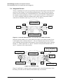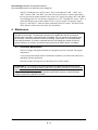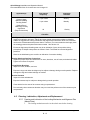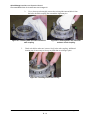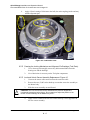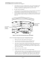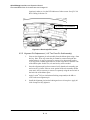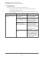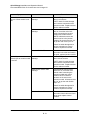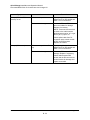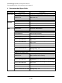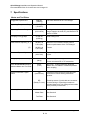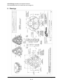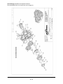
1
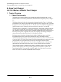
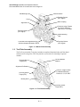
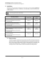
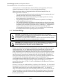
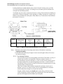
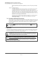
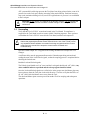
Quick-Change Installation and Operation Manual Document #9620-20-b-1210 series base tool changer-08 Table of Contents B. Base Tool Changer ......................................................................................................2 QC-1210 Series—Robotic Tool Changer ........................................................................2 1. Product Overview ....................................................................................................... 2 1.1 Master Plate Assembly....................................................................................... 2 1.2 Tool Plate Assembly .......................................................................................... 3 1.3 Optional Modules ............................................................................................... 4 2. Installation .................................................................................................................. 5 2.1 Master Interface ................................................................................................. 5 2.2 Tool Interface ..................................................................................................... 6 2.3 Tool Stand Design ............................................................................................. 7 2.3.1 Tool Locating Features ........................................................................... 8 2.3.2 Tool Stand Sensors ................................................................................ 9 2.4 Pneumatic and Electrical Connections ............................................................... 9 3. Operation .................................................................................................................... 9 3.1 Coupling Sequence .......................................................................................... 10 3.2 Fail-Safe Operation .......................................................................................... 10 3.3 Uncoupling ....................................................................................................... 11 3.4 Integrated Sensors ........................................................................................... 12 4. Maintenance.............................................................................................................. 14 4.1 Preventive Maintenance ................................................................................... 14 4.2 Cleaning, Lubrication, Adjustment and Replacement ....................................... 15 4.2.1 Cleaning and Lubrication of the Locking Mechanism and Alignment Pins (Master Plate). ........................................................................................ 15 4.2.2 Cleaning the Locking Mechanism and Alignment Pin Bushings (Tool Plate). .................................................................................................... 17 4.2.3 Lock and Unlock Sensor Assembly Replacement. Figure 4.5 ............... 17 4.2.4 RTL Sensor Replacement (8mm Threaded Barrel Style). ..................... 18 4.2.5 Alignment Pin Replacement (1-1/8‖ Two Piece Pin Sub-Assembly)...... 19 5. Troubleshooting ....................................................................................................... 20 6. Recommended Spare Parts ..................................................................................... 23 7. Specifications ........................................................................................................... 24 8. Drawings ................................................................................................................... 25 Pinnacle Park 1031 Goodworth Drive Apex, NC 27539 Tel: 919.772.0115 Fax: 919.772.8259 www.ati-ia.com Email: [email protected] B-1 Quick-Change Installation and Operation Manual Document #9620-20-b-1210 series base tool changer-08 B. Base Tool Changer QC-1210 Series—Robotic Tool Changer 1. Product Overview 1.1 Master Plate Assembly The Master base assembly (Master plate) includes an anodized aluminum body, a set of hardened stainless-steel locking mechanisms, and hardened steel alignment pins (see Figure 1.1). The Master plate has (6) flat sides for mounting of optional modules. Flat „A‟ is dedicated for mounting of the control/signal module along with tool changer supply air that is provided through an air or valve adapter. Flats „B‟, „C‟, „D‟,‟E‟, and „F‟ are fully interchangeable and optional modules can be arranged to suit the application or robot dress, as required. The Master plate is comprised of (3) locking mechanisms. Each locking mechanism consists of a cam, male coupling, and chrome-steel balls. Tapered pins located on the Master plate mate with holes in the Tool plate to ensure repeatable alignment during the coupling process. Extreme pressure grease is applied to the cams, male couplings, ball bearings, and pins to enhance performance and maximize the life of the Master assembly. Proximity sensors (6 total) are designed into the body of the Master plate to verify the locked/unlocked position of each locking mechanism. Due to the multiple locking mechanism design, the proximity sensors are grouped such that (3) sensors are for Lock and (3) are for Unlock. The Lock/Unlock signal at each locking mechanism is routed to the signal junction module. The junction module provides the control/signal module with the Lock/Unlock state of the Master plate. See the cable routing illustrations in Section 3.4 to understand the relationship between the sensors, junction module and control module. Three proximity sensors are mounted in the body of the Master plate to verify Tool plate presence when coupled. The sensors provide (2) Ready-To-Lock (RTL) signals to the control/signal module. To accomplish a dual RTL signal, (2) of the sensors are wired in series. See Section 3.4 for more explanation of the RTL layout. Pinnacle Park 1031 Goodworth Drive Apex, NC 27539 Tel: 919.772.0115 Fax: 919.772.8259 www.ati-ia.com Email: [email protected] B-2 Quick-Change Installation and Operation Manual Document #9620-20-b-1210 series base tool changer-08 Ball Bearings (36) Junction Module Proximity Sensor (RTL Signal) Cam Male Coupling Alignment Pin Common Ledge Feature For Module Mounting; Flats A, B, C, D, E and F Proximity Sensor (RTL Signal) Cable Retaining Tabs Lock/Unlock Air Supplied through Air/Valve Adapter Mounted to Flat A Proximity Sensor (RTL Signal) Figure 1.1—Master Plate Assembly 1.2 Tool Plate Assembly The Tool base assembly (Tool plate) includes an anodized aluminum body and 3 hardened stainless-steel bearing races. The Tool plate has (6) flat sides for mounting of optional modules. Junction Module Adapter Proximity Sensor Target (RTL) Alignment Pin Bushing Common Ledge Feature For Module Mounting; Flats A, B, C, D, E and F Proximity Sensor Target (RTL) Bearing Race Proximity Sensor Target (RTL) Figure 1.2—Tool Plate Assembly Pinnacle Park 1031 Goodworth Drive Apex, NC 27539 Tel: 919.772.0115 Fax: 919.772.8259 www.ati-ia.com Email: [email protected] B-3 Quick-Change Installation and Operation Manual Document #9620-20-b-1210 series base tool changer-08 1.3 Optional Modules There are (6) flats available for mounting of the optional modules for support of various utility pass-through, such as signal, fluid/air, and power. For assistance in choosing the right modules for your particular application, visit our website to see what is available or contact an ATI Sales Representative directly. In general, flat „A‟ is reserved for an air/valve adapter module and a control/signal module. Flat „D‟ is reserved for a signal junction module, however, optional utility modules can still be added on flat „D‟. Modules for flats „B‟, „C‟, „D‟, „E‟, or „F‟ are interchangeable to suit the application or the dress-out required. The optional modules are mounted to the Master or Tool plate using a common ledge mounting feature. Only (2) M6 SHCS fasteners need to be unscrewed in order to remove the module from the Master/Tool plate. A secondary mounting support, called a “cleat”, is factory-installed to the Master and Tool plate on each flat that is occupied with a module. The cleats provide additional module support for those situations when hoses or cables may inadvertently be snagged or pulled and may otherwise result in damage to the module. If modules are added to a tool changer in the field, then the Master and Tool plates may have to be uninstalled to facilitate the cleat installation. Pinnacle Park 1031 Goodworth Drive Apex, NC 27539 Tel: 919.772.0115 Fax: 919.772.8259 www.ati-ia.com Email: [email protected] B-4 Quick-Change Installation and Operation Manual Document #9620-20-b-1210 series base tool changer-08 2. Installation All fasteners used to mount the Tool Changer to the robot and to user Tools should be tightened to a torque value as indicated below. Furthermore, removable (blue) Loctite® 242 must be used on these fasteners. ! CAUTION: Care should be taken to select fasteners for mounting that are not too long, such that a gap is formed at the interface. Mounting conditions Master Plate to RIP (6061-T6 aluminum) Minimum thread engagement of 15mm (0.59‖) [1.5X fastener Ø] Master Plate to RIP (Steel; USS ≥ 90KSI) Minimum thread engagement of 15mm (0.59‖) [1.5X fastener Ø] Tool Plate (aluminum) to End-Effector Interface Plate (6061-T6 aluminum) Fastener Size and Property Class Maximum Recommended Torque M10–1.5 75 Nm Class 12.9 (55 ft-lbs.) M10–1.5 75 Nm Class 12.9 (55 ft-lbs.) M10–1.5 52 Nm Class 12.9 (38 ft-lbs.) M10–1.5 52 Nm Class 12.9 (38 ft-lbs.) Minimum thread engagement of 15mm (0.59‖) [1.5X fastener Ø] Tool Plate (aluminum) to End-Effector Interface Plate (7075-T6 aluminum) Minimum thread engagement of 15mm (0.59‖) [1.5X fastener Ø] 2.1 Master Interface The Master assembly is attached to the robot interface plate (RIP), and both are bolted to the robot arm. The RIP is designed with mounting features such as a boss and/or bolt and dowel holes. These features are used to accurately position and secure the Master to the robot. The RIP is utilized to adapt the Master plate to a specific robot flange that is not compatible with the Master plate mounting features. Custom RIPs are available upon request. (Refer to drawings in Section 8 of this manual for technical information on mounting features.) Pinnacle Park 1031 Goodworth Drive Apex, NC 27539 Tel: 919.772.0115 Fax: 919.772.8259 www.ati-ia.com Email: [email protected] B-5 Quick-Change Installation and Operation Manual Document #9620-20-b-1210 series base tool changer-08 Robot Wrist Flange Robot Interface Plate With Fasteners and Dowel Pins Master Plate, with Fasteners to Robot Interface Plate Tool Plate, with Fasteners to Tool Interface Plate Tool Interface Plate (Fasteners and Dowel Pins Not Shown) Figure 2.1—Typical Installation (QC-1210 Shown) If the customer chooses to design and build a robot interface plate, the following should be considered: The interface plate should be designed to include bolt holes for mounting, dowel pins, and a boss for accurate positioning on the robot and Master plate. The thickness of the interface plate must be great enough to provide the necessary thread engagement for the mounting bolts. The interface plate must be properly designed to provide rigid mounting to the Master plate boss area. The plate design should take into account clearances required for Tool Changer module attachments and accessories. 2.2 Tool Interface The Tool plate is attached to customer-supplied tooling. The Tool plate is designed with mounting features such as a bolt and dowel holes. These features are used to accurately position and secure the end-effector. Most often an End-effector Interface Plate (EIP) is utilized to adapt the Tool plate to an end-effector that is not compatible with the Tool plate Pinnacle Park 1031 Goodworth Drive Apex, NC 27539 Tel: 919.772.0115 Fax: 919.772.8259 www.ati-ia.com Email: [email protected] B-6 Quick-Change Installation and Operation Manual Document #9620-20-b-1210 series base tool changer-08 mounting features. Custom End-effector Interface Plates can be supplied by ATI to meet customer requirements (see Figure 2.1) (refer to the application drawing). When the customer chooses to design and build an End-effector Interface Plate, the following should be considered: The interface plate should be designed to include bolt holes for mounting and dowel pins that mate with Tool body for accurate positioning. The thickness of the interface plate must be great enough to provide the necessary thread engagement for the mounting bolts. The plate design should take into account clearances required for Tool Changer module attachments and accessories. The End-effector Interface Plate should be designed with a set of holes in the center of each of the three locking mechanisms to allow for manually returning the locking mechanisms to the unlocked position under adverse conditions (i.e., unintended loss of power and/or air pressure). The center access holes should be kept small [recommended hole diameter: 25.4mm (1”)] to prevent debris from contaminating the locking mechanism while operating in dirty environments. 2.3 Tool Stand Design ! CAUTION: Tool Stand design is critical to proper operation of the Tool Changer. Improperly designed Tool Stands can cause misalignments that will cause jamming and/or excessive wear of Tool Changer components. Z-Compliance is required for the Tool Stand, in order to ensure that the Master remains fully contacted with the Tool prior to issuing the Unlock command. ! CAUTION: During coupling and lock-up, the Tool Stand must allow for movement (float) in a plane parallel to the mating surfaces of the Master plate and Tool plates, and in a direction perpendicular to this plane, towards the Master plate. In most cases, the tools are stored in a Tool Stand when not being used by the robot. During coupling and lock-up, the Tool Stand must allow for movement (float) in a plane parallel with the mating surfaces of the Master plate and Tool plates (X and Y directions). Even slight misalignment between the Master plate and Tool plate can generate high forces during lock-up if the Tool plate is not allowed to float into place during lock-up. These high forces can cause excessive wear and even jamming of the end-effector and robot. The degree of float required depends on the accuracy of the robot‟s positioning and the repeatability of the Tool location in the Tool Stand during lock-up. See Figure 2.2 and Table 2.3 for recommended maximum allowable float (offsets) prior to coupling. The Tool Stand should be designed to minimize misalignment during coupling and uncoupling. In some cases, greater offsets than shown in Table 2.3 can be accommodated by the Master and Tool plates, but will increase wear. For the QC-1210, the tool stand should have compliance in the Z direction. The robot should be programmed to fully seat the Tool in the Tool Stand before issuing the Unlock command. The Unlock sensors need to be active before pulling the Master away. It is possible to design Tool Stands that hold Tools in the horizontal position, but care must be taken that the necessary compliance is provided during coupling and uncoupling. In general, “horizontalposition” Tool Stands cause more wear on the locking mechanism and locating features of the Tool and Tool Stand. Pinnacle Park 1031 Goodworth Drive Apex, NC 27539 Tel: 919.772.0115 Fax: 919.772.8259 www.ati-ia.com Email: [email protected] B-7 Quick-Change Installation and Operation Manual Document #9620-20-b-1210 series base tool changer-08 Lock-up should occur with the Master plate in the No-Touch™ Locking zone (see Table 2.3), but not touching the Tool plate. As locking occurs, the Master plate should draw the Tool plate into the locked position. Tool Stands may also need to incorporate means for covering Tools and electrical modules to protect them in dirty environments, such as grinding or welding. Alternatively, locating Tool Stands in areas shielded from weld spatter, fluids, adhesives, or other debris would eliminate the need for Tool covers. Cocking Offset (About X and Y) X, Y and Z Offset Figure 2.2—Offset Definitions Model No-Touch Zone Z Offset (Max)* (mm) X and Y Offset (Max)† (mm) Cocking Offset (Max) (degrees) Twisting Offset (Max) (degrees) QC-1210 1 ±2 ±0.7 ±1 Table 2.3—Maximum Recommended Offsets Prior to Coupling Notes: * Maximum values shown. Decreasing actual values will minimize wear during coupling/uncoupling. † Actual allowable values may be higher in some cases but higher offsets will increase wear during coupling. 2.3.1 Tool Locating Features The Tool must be positively and repeatably located in the Tool Stand. A variety of methods may be used to accomplish this. Whatever method is chosen, it is important that the required compliance or “float” be built into the locating system. A common method is to use tapered alignment pins in holes. As the Tool plate is lifted during locking, the taper lets the Tool float into its locked position even with small deviations in robot position. Other Tool locating feature methods include balls and detents, dowel pins in notched V-grooves, etc. Please consult ATI for recommendations or assistance with locating feature design for your particular tooling. Straight cylindrical dowel pins should not be used as they provide too much surface engagement. During coupling and uncoupling the Tool can bind on these pins due to misalignment of the Master and Tool plates. Pinnacle Park 1031 Goodworth Drive Apex, NC 27539 Tel: 919.772.0115 Fax: 919.772.8259 www.ati-ia.com Email: [email protected] B-8 Quick-Change Installation and Operation Manual Document #9620-20-b-1210 series base tool changer-08 Robot programming and location repeatability are vital in Tool pick-up and dropoff. 2.3.2 Tool Stand Sensors It is highly suggested that the customer provide a sensor that detects the presence of a properly seated Tool in the Tool Stand. The sensor may be used prior to coupling to ensure there is a Tool properly seated in the stand. Sensors may also be used as the robot starts to move away after uncoupling. This provides a fail-safe measure in the event that a Tool should become jammed in the stand or if the Tool should fail to release properly from the robot. Proximity sensors should be located so that the sensing face is vertical to prevent metal shavings, weld spatter, or other debris from falling on the sensor and creating false readings. 2.4 Pneumatic and Electrical Connections The air supply used for coupling and uncoupling the Tool Changer should be clean, dry, and non-lubricated. A supply pressure in the range of 70 to 100 psi is acceptable for operation of the locking mechanism, with a setting of 80 psi suggested. The air should be filtered 50 micron or better. ! CAUTION: Do not use the Tool Changer in the fail-safe condition. Do not transport the Tool Changer in the fail-safe condition. Possible damage to the locking mechanism could occur. 3. Operation The Master locking mechanisms are pneumatically-driven to couple and uncouple with the bearing races on the Tool plate. The Master plate utilizes air ports from an air or valve adapter module to provide Lock and Unlock pressure to the locking mechanism. ! CAUTION: Safe, reliable operation of the Tool Changer is dependent on a continuous supply of compressed air at a pressure of 70–100 psi. Robot motion should be halted if the air supply pressure drops below 70 psi for any reason. ATTENTION: All Tool Changers are initially lubricated using MobilGrease® XHP222 Special grease. The end user must apply additional lubricant to the locking mechanism components and alignment pins prior to start of service (See Section 4.2). Tubes of lubricant for this purpose are shipped with every Tool Changer. Note: MobilGrease® XHP222 Special is a NLGI #2 lithium complex grease with molybdenum disulfide. Pinnacle Park 1031 Goodworth Drive Apex, NC 27539 Tel: 919.772.0115 Fax: 919.772.8259 www.ati-ia.com Email: [email protected] B-9 Quick-Change Installation and Operation Manual Document #9620-20-b-1210 series base tool changer-08 3.1 ! Coupling Sequence CAUTION: The locking mechanism must be in the Unlock position when attempting to couple the Tool Changer. Failure to adhere to this condition may result in damage to the unit and/or the robot. Position the Master above the Tool and move the Master into locking position. The mating surfaces of the Master and Tool should be parallel and not touching. Make sure that the tapered alignment pins from the Master enter the alignment holes on the Tool. The alignment pins should be relatively concentric with the alignment holes such that they do not rub against the edge. The locking mechanisms allow the Master to “pull up” the Tool with certain gaps between the two sides. It is recommended that the mating faces of the Master and Tool not be touching, but be within 0.040” (1 mm) of each other when coupling to minimize stress and wear on the locking mechanism. RTL (Ready-To-Lock) sensing is built into the Tool Changer, providing the ability to sense Tool proximity to the Master prior to coupling. The mating faces of the Master and Tool must be positioned within approximately 0.055–0.065” (1.40–1.65mm) of each other for the sensors to detect Tool presence. RTL signals are not required to couple the Tool Changer, but are essential as a further confirmation of coupling prior to removing the Tool from the tool stand. TM ! CAUTION: No-Touch locking technology allows the unit to couple with a separation distance between the Master and Tool. Direct contact of the Master and Tool mating surfaces is allowed just prior to coupling, ONLY if Z compliance is built in to the Tool Stand. Verify that all the RTL signals are read as “on” (true). Turn the Unlatch output off. Turn the Latch output on. Air is supplied to the locking mechanism to couple the Tool Changer. A sufficient delay must be programmed between the Latch output being activated and reading the state of the Lock/Unlock signals, so that the coupling process is completed before checking the Locked state. Read the Lock and Unlock signals. The Lock signal should read “on” (true) and the Unlock signals should read “off” (false). 3.2 Fail-Safe Operation In the event of air supply loss to the locking mechanism, the Tool Changer will not uncouple. A slight separation between the Master and Tool plates occurs just after air loss, but at this point the locking balls become trapped and cannot move without air pressure being applied to the Unlock port. This feature provides the Tool Changer with a fail-safe mechanism. Pinnacle Park 1031 Goodworth Drive Apex, NC 27539 Tel: 919.772.0115 Fax: 919.772.8259 www.ati-ia.com Email: [email protected] B - 10 Quick-Change Installation and Operation Manual Document #9620-20-b-1210 series base tool changer-08 ATI‟s patented fail-safe design prevents the Tool plate from being released in the event of air pressure loss to the Lock port, thereby increasing safety and reliability. Positional accuracy may not be maintained during air loss, but will be regained once air pressure is re-established to the Lock port. ! 3.3 CAUTION: Do not use the Tool Changer in the fail-safe condition. Do not transport the Tool Changer in the fail-safe condition. Possible damage to the locking mechanism could occur. Uncoupling Verify that the Tool is FULLY secured and seated in the Tool Stand. Z-compliance is required for the Tool Stand in order to ensure reliable Unlocking sequence. Once you have verified that the Tool is FULLY secured in the Tool Stand, turn the Latch output off. ! CAUTION: This Tool Changer may be equipped with a Tool Stand Interlock (TSI) feature that physically breaks the Unlatch solenoid circuit. Use of the TSI will prevent any unwanted Unlatch software commands from being recognized until the circuit is made. See user manual of the respective control module for details and troubleshooting. Issue the Unlatch output. Air is supplied to the locking mechanism to uncouple the Tool Changer. A sufficient delay must be programmed between the Unlatch output being activated and reading the state of the Lock/Unlock signals, so that the coupling process is completed before checking the Locked state. Read the Lock and Unlock signals. The Unlock signal should read “on” (true) and the Lock signal should read “off” (false). Any other condition indicates a problem and the robot program should be halted. Once the Lock and Unlock signals are verified to be in the proper state, the Master plate may be moved away from the Tool plate in the axial direction. Check to verify that the RTLs are all “off” (false) after the Master moves away from the Tool. The robot and Master plate can now proceed to another Tool for coupling and subsequent operations. Pinnacle Park 1031 Goodworth Drive Apex, NC 27539 Tel: 919.772.0115 Fax: 919.772.8259 www.ati-ia.com Email: [email protected] B - 11 Quick-Change Installation and Operation Manual Document #9620-20-b-1210 series base tool changer-08 3.4 Integrated Sensors The QC-1210 Master has a total of (6) proximity sensors for detecting the Lock and Unlock state of the Tool Changer. For each locking mechanism there is one Lock sensor and one Unlock sensor. Each sensor pair is distinguished by the corresponding locking mechanism. For example, locking mechanism #1 has “L1” (Lock sensor #1) and “U1” (Unlock sensor #1). Also, to eliminate confusion, the Master body, sensor cables, and junction module connectors are labeled the same way (L1, U1, L2, U2, L3, and U3). QC-1210 Master U1 U3 1 RS1 RS3 L1 L3 Flat A / Control Module Figure 3.1—Lock and Unlock sensors. “L2” and “U2” not visible in this view Inside the junction module, all (3) Lock sensors are wired in series which provides for one Locked signal via the connector labeled “L”. The (3) Unlocked sensors are also wired in series within the junction module which provides for one Unlocked signal via the connector labeled “U”. Cables connect the “L” and “U” connectors of the junction module to the “L” and “U” connectors of the control module. U1, L1, U2, and L2 (not visible in this view) Control Module QC-1210 Master U2 1 Junction Module R1, R2, U, and L L2 RS3 U3, L3, U, and L Figure 3.2—Connector view Figure 3.3 and Table 3.1 show the cables pertaining to the Lock and Unlock sensors. From the factory, the cables will be labeled to match where they are connected. Pinnacle Park 1031 Goodworth Drive Apex, NC 27539 Tel: 919.772.0115 Fax: 919.772.8259 www.ati-ia.com Email: [email protected] B - 12 Quick-Change Installation and Operation Manual Document #9620-20-b-1210 series base tool changer-08 Figure 3.3—Sensor Cable Routing Sensor Cable Routing Lock/Unlock Sensor ID L1 L2 L3 U1 U2 U3 # <3> <3> <3> <3> <3> <3> # <4> <5> <4> <4> <5> <4> Junction Module Connector L1 L2 L3 U1 U2 U3 L U # 9121-XXX-M Control Module Connector <6> <6> L U # RTL Sensor ID RS1 R1 <1> RS2 R2 Cable # from Fig. 3.3 <2> RS3 ATI Part Number PNP with LED Cables (-SL Models) NPN with LED Cables (-SE Models) <1> 9120-C-3PF-3PF-3PM90 9120-C-3PF-3PF-3PM90-NPN <2> 9120-C-3PF-3PM90-0030 9120-C-3PF-3PM90-0030-NPN <3> 9005-20-1613 9005-20-1780 <4> 9120-C-3M5F-3PM90-0020 9120-C-3M5F-3PM90-0020 <5> 9120-C-3M5F-3PM90-0016 9120-C-3M5F-3PM90-0016 <6> 9120-C-3PF90-3PM90-0041 9120-C-3PF90-3PM90-0041-NPN Table 3.1—Cable Number Pinnacle Park 1031 Goodworth Drive Apex, NC 27539 Tel: 919.772.0115 Fax: 919.772.8259 www.ati-ia.com Email: [email protected] B - 13 Quick-Change Installation and Operation Manual Document #9620-20-b-1210 series base tool changer-08 The QC-1210 Master has (3) RTL sensors. They are designated as “RS1”, “RS2”, and “RS3”. Sensors “RS1” and “RS2” are wired in series (by means of a splitter cable) and in this way provide the control module with a single “R1” signal. Only when “RS1” and “RS2” are both triggered will a Tool presence signal occur at “R1”. The third RTL sensor, “RS3”, is connected directly to the control module at “R2” to give a second Tool presence signal. Figure 3.3 and Table 3.1 show the cables pertaining to the RTL sensors. The labels on the cables indicate which sensors the cables are connected to. 4. Maintenance ATTENTION: The cleanliness of the work environment strongly influences the trouble-free operation of the changer. The dirtier the environment, the greater the need is for protection against debris. Protection of the entire EOAT, the Master, the Tool, and all of the modules may be necessary. Protective measures include the following: 1) placement of Tools Stands away from debris generators, 2) covers incorporated into the Tool Stands [see Section 2.3] and 3) guards, deflectors, air curtains, and similar devices built into the EOAT and the Tool Stand. 4.1 Preventive Maintenance The Tool Changer and optional modules are designed to provide a long life with regular maintenance. A visual inspection and preventative maintenance schedule is provided in the table below depending upon the application. Detailed assembly drawings are provided in Section 8 of this manual. ATTENTION: All Tool Changers are initially lubricated using MobilGrease® XHP222 Special grease. The end user must apply additional lubricant to the locking mechanism components and alignment pins prior to start of service (See Section 4.2). Tubes of lubricant for this purpose are shipped with every Tool Changer. Note: MobilGrease® XHP222 Special is a NLGI #2 lithium complex grease with molybdenum disulfide. Pinnacle Park 1031 Goodworth Drive Apex, NC 27539 Tel: 919.772.0115 Fax: 919.772.8259 www.ati-ia.com Email: [email protected] B - 14 Quick-Change Installation and Operation Manual Document #9620-20-b-1210 series base tool changer-08 Application(s) General Usage Material Handling Docking Station Welding/Servo/ Deburring, Foundry Operations (Dirty Environments) Tool Change Frequency Inspection Schedule > 1 per minute Weekly < 1 per minute Monthly All Weekly Checklist Balls/Alignment Pins/Holes/Bearing Race Inspect for lubrication and wear. A NLGI #2, lithium-based grease with molybdenum disulfide additive is suggested for locking mechanism and alignment pin lubrication. Over time, lubricants can become contaminated with process debris. Therefore, it is recommended to thoroughly clean the existing grease and replace with new as needed. See Section 4.2. Excessive alignment pin/bushing wear may be an indication of poor robot position during pickup/drop-off. Adjust robot position as needed. Check Tool Stand for wear and alignment problems. Wear on the balls/bearing race could be an indication of excessive loading. Mounting Hardware/Interface Connections Inspect for proper torque and interference or wear, abrasions, cuts of hoses, and electrical cables. Tighten and correct as required. O-rings/Rubber Bushings Inspect for wear, abrasion, and cuts. Exposed o-rings and rubber bushings may be subject to damage during normal operation. Replace damaged o-rings and rubber bushings as needed. Electrical Contacts Inspect for wear and abrasion. Exposed contacts may be subject to damage during normal operation. Clear debris from the area of the contacts using compressed air. Do not directly clean contacts as abrasion may occur and the performance of the contact may be compromised. 4.2 Cleaning, Lubrication, Adjustment and Replacement 4.2.1 Cleaning and Lubrication of the Locking Mechanism and Alignment Pins (Master Plate). 1. The locking mechanism must be in the unlock state before cleaning. Pinnacle Park 1031 Goodworth Drive Apex, NC 27539 Tel: 919.772.0115 Fax: 919.772.8259 www.ati-ia.com Email: [email protected] B - 15 Quick-Change Installation and Operation Manual Document #9620-20-b-1210 series base tool changer-08 2. Use a clean rag to thoroughly remove the existing lubricant and debris from the balls, the male coupling, the cam and the alignment pins. Figure 4.1—Cleaning balls and outer surfaces of male coupling 3. Figure 4.2—Cleaning balls, cam, and inner surfaces of male coupling Check each ball to make sure it moves freely in the male coupling. Additional cleaning may be necessary to free up any balls that are sticking in place. Figure 4.3—Checking balls to move freely Pinnacle Park 1031 Goodworth Drive Apex, NC 27539 Tel: 919.772.0115 Fax: 919.772.8259 www.ati-ia.com Email: [email protected] B - 16 Quick-Change Installation and Operation Manual Document #9620-20-b-1210 series base tool changer-08 4. Apply a liberal coating of lubricant to the balls, the male coupling (inside and out), and the alignment pins. Figure 4.4—Lubrication areas 4.2.2 Cleaning the Locking Mechanism and Alignment Pin Bushings (Tool Plate). 1. Use a clean rag to thoroughly remove any lubricant and debris from the bearing race and the bushings. 2. No re-lubrication is necessary on the Tool plate components. 4.2.3 Lock and Unlock Sensor Assembly Replacement. Figure 4.5 ! 1. Unscrew the sensor cable connector from the extension cable. 2. Remove the two (2) M3 socket head cap screws that secure the assembly to the Master body. 3. Slide the sensor assembly out and discard. CAUTION: The Lock and Unlock sensor assemblies are precision aligned and permanently assembled at the factory. Do not attempt to adjust the position of the sensor or severe damage to the Master may occur. 4. Apply Loctite 222MS to the new M3 socket head cap screws supplied with the new sensor assembly. Pinnacle Park 1031 Goodworth Drive Apex, NC 27539 Tel: 919.772.0115 Fax: 919.772.8259 www.ati-ia.com Email: [email protected] B - 17 Quick-Change Installation and Operation Manual Document #9620-20-b-1210 series base tool changer-08 5. Check that the new sensor assembly has the o-ring present and that the old oring came off of the Master with the old sensor assembly. Attach the new assembly to the Master by tightening the M3 screws to 12 in-lbs. 6. Re-attach cables and modules. 7. Confirm operation of the Unlock sensor by issuing the Unlatch command and then checking to see that the LED in the Unlock sensor body is on. 8. Confirm operation of the Lock sensor by issuing the Latch command to lock a Tool to the Master and then checking to see that the LED in the Lock sensor body is on. Unlock Sensor Assembly (3 Places) Lock Sensor Assembly (3 Places) Figure 4.5—QC-1210 Lock and Unlock Sensor Assemblies 4.2.4 RTL Sensor Replacement (8mm Threaded Barrel Style). 1. Remove the sensor cable connector from the sensor. 2. Loosen the jam nut securing the sensor to the Master body. 3. Unscrew/remove the sensor from the Master and discard. 4. Screw the new sensor/cable assembly into the Master body until the face of the sensor is flush with the surrounding face of the Master body. Turn the sensor back ¼ turn. Use a crowfoot and a torque wrench to tighten the jam nut to 20 in-lbs of torque. 5. Replace the sensor cable if needed. 6. Re-attach the cable connector to the control/signal module. 7. Confirm operation of the new sensor by bringing a metallic object into close proximity to the face of the sensor and watching for the LED in the body of the sensor to come on. ATTENTION: “R1” consists of sensors “RS1” and “RS2” wired in series. Therefore, a metallic object has to be used at both Pinnacle Park 1031 Goodworth Drive Apex, NC 27539 Tel: 919.772.0115 Fax: 919.772.8259 www.ati-ia.com Email: [email protected] B - 18 Quick-Change Installation and Operation Manual Document #9620-20-b-1210 series base tool changer-08 locations in order to view the LED indicator of either sensor. See QC-1210 RTL Cabling in Section 3.4. 1 of 3 Ready-To-Lock Sensors Figure 4.6—Barrel-style RTL sensor 4.2.5 Alignment Pin Replacement (1-1/8‖ Two Piece Pin Sub-Assembly) 1. Unscrew the alignment pin sub-assembly from the Master plate using a 5mm hex key. Note: If for any reason the pin cannot be removed using the hex socket in the tip, it may be necessary to remove it by other means such as Vise Grip pliers. Another approach is to use the access hole in the back side of the Master plate. In this case, a 4 mm hex key will be needed. 2. Once the alignment pin has been removed verify that the sub-assembly (pin and set screw) is intact. If the set screw portion of the sub-assembly did not come out it will be necessary to remove it separately using the access hole in the back side of the Master plate. 3. Apply Loctite® 242 (or similar thread locking compound) to the M8 set screw in the new alignment pin. 4. Install the alignment pin into the bushing and screw it into place. Apply 60 in-lb of torque to fully tighten it. Pinnacle Park 1031 Goodworth Drive Apex, NC 27539 Tel: 919.772.0115 Fax: 919.772.8259 www.ati-ia.com Email: [email protected] B - 19 Quick-Change Installation and Operation Manual Document #9620-20-b-1210 series base tool changer-08 5. Troubleshooting Check these conditions for all symptoms prior to troubleshooting: Proper pneumatic and electrical connections have been made to the Tool Changer. Air is supplied at a minimum of 70 psi. No air or vacuum can be trapped in a de-energized Lock or Unlock port (pressure must be vented to atmosphere). Symptom Unit will not Lock or Unlock or the locking mechanisms are jammed. Cause Resolution The ball bearings and/or cam are not moving freely in the male coupling. Clean and lubricate as needed to restore smooth operation (see Section 4—Maintenance). The Master and Tool are not within the specified No-Touch zone when attempting to Lock. Check that the Tool is properly seated in the Tool Stand. Reteach the robot to bring the Master and Tool closer together before attempting to Lock. Master and Tool are not parallel (all three RTL sensors are not on when trying to lock). Check that the Tool is properly seated in the Tool Stand. Reteach the robot to bring the Master and Tool closer together and parallel prior to attempting to Lock. Verify RTLs (RS1, RS2, and RS3) are all on. Tool Drop-off Distance is too large. Check that the Tool is properly positioned in the Tool Stand and the Tool is fully seated. Check that the UNLATCH command is not being issued with the Tool sitting above the Tool Stand and the robot is not trying to ―drop‖ the Tool into the nest. Pinnacle Park 1031 Goodworth Drive Apex, NC 27539 Tel: 919.772.0115 Fax: 919.772.8259 www.ati-ia.com Email: [email protected] B - 20 Quick-Change Installation and Operation Manual Document #9620-20-b-1210 series base tool changer-08 Symptom Unit is fully locked but Locked input to control module is not ON Cause Individual Lock sensor/cable damage. Resolution Check LED light on each of the three Lock sensors. If OFF check for cable damage and a secure connection to the junction module. Replace sensor and/or cable as needed. Main Lock sensor cable damage. If all individual Lock sensor LEDs are on, check the main Lock cable connecting the junction module and control module. NOTE: Individual sensors are wired in series in the junction module. All sensors must be ―on‖ to get the main Lock input ―on‖. Check for cable damage and a secure connection to control module. Replace as needed. Unit is fully unlocked but Unlock input to control module is not ON. Junction Module failure. If individual Lock sensors/cables and main Lock cable are found to be good, replace junction module. Individual Unlock sensor/cable damage. Check LED light on each of the three Unlock sensors. If OFF check for cable damage and a secure connection to the junction module. Replace sensor and/or cable as needed. Main Unlock sensor cable damage. If all individual Unlock sensor LEDs are on, check the main Unlock cable connecting the junction module and control module. NOTE: Individual sensors are in series in the junction module. All sensors must be ―on‖ to get the main Unlock input ―on‖. Check for cable damage and a secure connection to control module. Replace as needed. Junction Module failure. If individual Unlock sensor/cables and main Unlock cable are found to be good, replace control module. Pinnacle Park 1031 Goodworth Drive Apex, NC 27539 Tel: 919.772.0115 Fax: 919.772.8259 www.ati-ia.com Email: [email protected] B - 21 Quick-Change Installation and Operation Manual Document #9620-20-b-1210 series base tool changer-08 Symptom R1 input (RS1 and RS2 sensors) not on. Cause Resolution Master not in position. Reprogram pick-up point so Master and Tool are parallel and within 1 mm of each other. Sensor/cable damage. Check the RS1 and RS2 sensor faces and cables for damage. Replace if necessary. NOTE: These sensors are wired in series in the cable harness. Both sensors must be ―on‖ to get the R1 (RTL1) input ―on‖. Check splitter cable from R1 connector at the control module to RS1 and RS2 sensors. Replace as needed. R2 input (RS3 sensor) not on. Master not in position at Pickup. Reprogram pick-up point so Master and Tool are parallel and within 1 mm of each other. Sensor/cable damage. Check the RS3 sensor face for damage. Replace if necessary. Check cable between RS3 sensor and the R2 connector at control module for damage and replace as needed. Pinnacle Park 1031 Goodworth Drive Apex, NC 27539 Tel: 919.772.0115 Fax: 919.772.8259 www.ati-ia.com Email: [email protected] B - 22 Quick-Change Installation and Operation Manual Document #9620-20-b-1210 series base tool changer-08 6. Recommended Spare Parts Assembly Master Plate Part Number Description 9121-1210AM-0-0-0-0-0-0 Complete QC-1210 Master Plate, No Options 9005-20-1569 1-1/8‖ Two Piece Alignment Pin 9005-20-1198 Master Cleat Assy. See Section 8 for Additional Information Tool Plate 9121-1210AT-0-0-0-0-0-0 Complete QC-1210 Tool Plate, No Options 9005-20-1199 Tool Cleat Assy. See Section 8 for Additional Information Other 9005-20-1605 Tool Junction Module Adapter PNP with LED Cables (-SL) 8590-9909999-34 PNP Proximity Sensor (RTL) 9005-20-1604 PNP Master Signal Junction Module 9005-20-1613 PNP Lock/Unlock Sensor Assembly 9120-C-3M5F-3PM90-0016 L/U Cable, Pentafast Female Straight to Picofast Male Right Angle, 0.16 m 9120-C-3M5F-3PM90-0020 L/U Cable, Pentafast Female Straight to Picofast Male Right Angle, 0.20 m 9120-C-3PF-3PF-3PM90 PNP RTL Cable, RS1 & RS2 to R1 9120-C-3PF-3PM90-0030 PNP RTL Cable, RS3 to R2 9120-C-3PF90-3PM90-0041 PNP L/U Cable, Picofast Female Right Angle to Picofast Male Right Angle, .41 m NPN with LED Cables (-SE) 8590-9909999-34 PNP Proximity Sensor (RTL) 9005-20-1780 NPN Lock/Unlock Sensor Assembly 9005-20-1781 NPN Master Signal Junction Module 9120-C-3M5F-3PM90-0016 L/U Cable, Pentafast Female Straight to Picofast Male Right Angle, 0.16 m 9120-C-3M5F-3PM90-0020 L/U Cable, Pentafast Female Straight to Picofast Male Right Angle, 0.20 m 9120-C-3PF-3PF-3PM90-NPN NPN RTL Cable, RS1 & RS2 to R1 9120-C-3PF-3PM90-0030-NPN NPN RTL Cable, RS3 to R2 9120-C-3PF90-3PM90-0041-NPN NPN L/U Cable, Picofast Female Right Angle to Picofast Male Right Angle, .41 m Pinnacle Park 1031 Goodworth Drive Apex, NC 27539 Tel: 919.772.0115 Fax: 919.772.8259 www.ati-ia.com Email: [email protected] B - 23 Quick-Change Installation and Operation Manual Document #9620-20-b-1210 series base tool changer-08 7. Specifications Master and Tool Plates Suggested Payload Limit 2980 lbs. (1350 kg) Operating Temperature Range Operating Pressure Range The mass attached to the Tool Changer. o -20–150 F o (-30–66 C) 70–100 psi (4.8–6.9 bar) Locking mechanism supply pressure operating range. Supply to be clean, dry, and filtered to 50 micron or better. Coupling Force @ 80psi 21,000 lbs. (9,525 kg) Axial holding force. Static Moment Capacity (X, Y) 48,000 in-lb 5,423 (Nm) Maximum recommended working load for optimum performance of the Tool Changer. 48,000 in-lb 5,423 (Nm) Torsion 0.0006 in. (0.015 mm) Repeatability tested at rated load at one million cycles. (Z) Positional Repeatability Weight (coupled, no access.) Max. Recommended distance between Master and Tool Plate Sensor Information, signal name 62 lbs. (28 kg) Master 18 kg / Tool 10 kg 0.04in. (1 mm) No-Touch locking technology allows the Master and Tool Plates to lock with separation when coupling. *Does not include RIP or TIP assemblies TM L/U (Lock/Unlock) RTL (Ready-To-Lock) Internal proximity sensors (6) with cable and connector to indicate locking mechanism position. Proximity sensors (3) with cable and connector for direct wiring to control/signal module to indicate Master and Tool mating surfaces within close proximity of each other. Mounting/Customer Interface Master Plate See Section 8 Tool Plate See Section 8 Pinnacle Park 1031 Goodworth Drive Apex, NC 27539 Tel: 919.772.0115 Fax: 919.772.8259 www.ati-ia.com Email: [email protected] B - 24 Quick-Change Installation and Operation Manual Document #9620-20-b-1210 series base tool changer-08 8. Drawings Pinnacle Park 1031 Goodworth Drive Apex, NC 27539 Tel: 919.772.0115 Fax: 919.772.8259 www.ati-ia.com Email: [email protected] B - 25 Quick-Change Installation and Operation Manual Document #9620-20-b-1210 series base tool changer-08 Pinnacle Park 1031 Goodworth Drive Apex, NC 27539 Tel: 919.772.0115 Fax: 919.772.8259 www.ati-ia.com Email: [email protected] B - 26 Quick-Change Installation and Operation Manual Document #9620-20-b-1210 series base tool changer-08 Pinnacle Park 1031 Goodworth Drive Apex, NC 27539 Tel: 919.772.0115 Fax: 919.772.8259 www.ati-ia.com Email: [email protected] B - 27