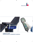
Download operon® b 710
Transcript
OPERON® B 710 User manual Contents Page 1. Introduction 1.1 1.2 1.3 4 General product description Proper use / Product liability information Notes on this user manual 2. Incoming goods inspection 5 3. Removing the operating table from the shipping pallet 5-6 4. Initial start-up 6 5. Important information for safe use (summary) 6-7 6. Product versions 8 6.1 6.2 Product version for North-America (only for information purpose) Other version-specific optional features 7. Overview of the operating table 8.1 8.2 8.3 8.4. 8.4.1 8.4.2 8.4.3 8.4.4 8.4.5 8.5 8.5.1 8.5.2 8.6 8.7 8.8 8.9 8.9.1 8.9.2 8.9.3 8.10 8.10.1 8.10.2 8.10.3 8.11 8.12 8.13 8 8 9 8. Functions and operational controls 2 4 4 4 10 - 32 Connection for control unit Overview of control unit Column control panel (override) Control of the motorised operating table functions / Explanation of symbols Basic functions of the operating table Drive unit function (optional feature) Function keys for operating table adjustments Additional functions Zero-position functions LED displays on control unit and column control panel LED displays for battery capacity / power supply Other LED displays Mains operation / Recharging the operating table batteries OR-table control Fuses for mains transformer Safety functions Anticollision function for powered adjustments Fault indicator Manual operation of castors Optional features Foot switch Drive unit Wireless remote control Components of the operating table top Mounting / Removing components Head plate adjustments User manual OPERON B 710 10 11 12 12 13 15 15 16 17 18 18 19 19 20 21 21 21 23 24 25 25 25 26 27 28 29 - 17 - 14 - 16 - 19 - 20 - 24 - 22 - 24 - 26 - 26 - 29 8.14 8.14.1 8.14.2 8.14.3 8.14.4 8.15 Optional features for the operating table top TUR module Divided leg plate pair Short back plate module Shoulder operating module Product version for North-America 9. Use of the operating table / Positioning the patient 9.1 9.2 9.3 9.4 9.4.1 9.5 9.6 9.6.1 9.6.2 9.7 9.7.1 9.7.2 9.8 9.8.1 9.8.2 9.9 9.10 General information Normal / Reverse orientation Patient positions for general surgery Semi-sitting patient positions Shoulder operations Lithotomy position Urology TUR module in normal orientation TUR module in reverse orientation Vascular surgery Patient positions in normal orientation Patient positions in reverse orientation Fitting the operating table top with divided leg plate pair MIS Gastric banding Unacceptable table top configurations Overview of operating table top module configurations 10. Care and maintenance 10.1 10.2 10.3 10.4 33 - 46 33 33 35 36 37 37 38 38 39 40 40 41 41 41 42 43 44 - 34 - 37 - 38 - 39 - 41 - 42 - 42 - 46 47 - 48 Cleaning and disinfaction / Daily care Monthly checks Annual maintenance Service software 11. Technical description 11.1 11.2 11.3 11.4 11.5 30 - 31 30 30 31 31 32 47 48 48 48 49 - 50 Technical data Electrical data Ambient conditions Symbols used on the type plate Symbols used on the OR table base User manual OPERON B 710 49 49 49 50 50 3 1. INTRODUCTION 1.1 General product description The OPERON® B 710 operating table is a mobile operating table with an electro-hydraulic drive for executing adjustments to the table top via mains or integrated batteries. These batteries can be recharged via the mains power supply. Control of the electro-hydraulically motorised functions is carried out via a control unit connected to the operating table by a spiral cable with a plug-in connection, alternatively via the control panel in the column. The operating table top itself is divided into 5 parts, whereby only the central section is permanently fixed to the foot/column construction. All other table top modules can be removed and the operating table or table top adjusted to meet the different requirements of the various surgical disciplines by means of diverse configurations. Both the cushions and the cushion support plates of the table top are radiotranslucent, so that the OPERON® B 710 guarantees perioperative use of the X-ray image amplifier over large longitudinal areas of the table top. In addition, guide rails are located beneath the entire length of the table top; these can be used for the insertion of conventional X-ray cartridges, with the aid of an optional X-ray cassette inserter, if required. 1.2 Intended use / Product liability information The operating table is intended exclusively for human medical purposes, i.e. for the treatment of ill or injured people by means of surgical and / or medical interventions. An essential prerequisite for using the operating table is proper assembly and maintenance of the unit, as well as observance of this User Manual. Introduction for use is confirmed by a handover certificate. BERCHTOLD will only consider itself responsible for the safety characteristics, reliability and capability if • the user has been fully instructed in correct use of the operating table. • assembly, new settings, modifications or repairs are only carried out by BERCHTOLD, or by an institution expressly authorised by BERCHTOLD. • the operating table is used under ambient conditions described in chapter 11.3 in medical rooms, whose electrical installation complies with the regulations of VDE 0100-710 and IEC 60364-7-10. • the operating table is used in full compliance with these user manual. 1.3 Notes on these instructions for use Inform yourself with the help of this User Manual on the correct use of the B 710 operating table, before using it for the first time. Keep these instructions near the place of use of the operating table and ensure that the user has access to them at all times. We have preceded important information in these manual with the following symbols: This symbol denotes safety-relevant information. Failure to observe the relevant instruction could result in damage or even injuries to the patient and / or the user. è This symbol precedes information which provides the user with special help, facilitates the use of the operating table, or helps to prevent faults. è Note: The symbols used on the operating table's type plate are described in chapter 11.4 4 User manual OPERON B 710 2. INSPECTION OF INCOMING GOODS Please check the operating table and accessories for any transport damage or defects immediately after receipt. For this purpose carry out the inspections listed in chapter 3. below, after removing the operating table from the shipping pallet. Claims for damages will be considered only if the vendor or forwarder is informed at once. A damage report must then be prepared immediately. The damage report must be submitted to the nearest BERCHTOLD representative or to BERCHTOLD directly, so that the claims for damages can be reported to the insurance company. When returning a unit to BERCHTOLD or a BERCHTOLD service branch, the original packaging should be used where possible. The following information must be included: owner's name and address, identification and serial number (see type plate), description of the defect. 3. REMOVING THE OPERATING TABLE FROM THE SHIPPING PALLET è Note: Never use sharp tools to open the packaging, as this could damage the contents. Attention! For safety reasons (operating table weight), the actual process of lifting the operating table from the shipping pallet have to be carried out by at least two staff members! The operating table is delivered upright on a shipping pallet. The wooden cover of the packaging can be used as descending ramp for the OR-table. Not all the modules of the operating table top are mounted; they are enclosed and secured separately, together with any other operating accessories supplied. In order to avoid damage, the operating table have to be removed from the pallet as follows: • • • • • • Remove the wooden cover and remove the packaging upward from the palette. Remove transportation locks and separately packed components. Remove all operating table top modules (see chapter 8.12). Loosen the wood strip from the palette, which is secured on the left side of the table by opening the screw. Attach the wooden cover of the packaging sideways to the palette to be used as descending ramp. Prepare the operating table for operation by setting the toggle switch 8, which is positioned at the head side of the table base, into the upper position (see chapter 8.7). • Switch on the operating table by activating the function key 2 “ON” on the column control panel and make it ready to start by activating the function keys 4 and 5 on the column control panel (see also chapter 8.4.1). • Hold the OR-table by the slidebar of the middle section and drive it carefully sideways down the descending ramp. • Immobilise the operating table again by activating function key 3 on the column control panel. User manual OPERON B 710 5 The following checks should then be performed: • Complete the operating table top by mounting all operating table top modules (see chapter 8.12). • Make the operating table ready to start again; first select the “move freely” status (see chapter 8.4.1) by activating function key 5 and check whether all castors roll easily and can be swivelled at full 360º. • Then select the “move with track stabilised” status by activating function key 6 and by slightly manoeuvring the operating table, check whether the track castor locks into place; then immobilise the operating table again. • Switch off the operating table at the column control panel again (function key 1) and connect the control unit 15 to the operating table; the plug-in connection for the control unit is located on the left hand side below the top frame of the central section (see also chapter 8.1). Then test all powered functions by adjusting every single function into their respective end positions and back into horizontal position again. • Check the voltage supply parameter by means of the type plate for correspondence with the present mains supply before connecting the OR table to the mains. Connect the mains charging cable and check that the charging function for the batteries is operating faultlessly (see Chap 8.6 / 8.7). 4. FIRST OPERATING OF THE OR TABLE The operator may only operate the OR table when the manufacturer or supplier • has subjected the operating table to a performance check at the place of use • and the persons responsible for operation have been instructed in the correct handling of the operating table with the aid of the instructions for use. 5. IMPORTANT INFORMATION ON SAFE HANDLING (SUMMARY) Incorrect operation or failure to comply with precautionary measures can cause serious incidents, and result in injuries to patient or staff, or damage to property. Therefore, please make sure that you are fully informed about the correct method of functioning and handling of the OPERON B 710 by reading this User Manual. Attention! When adjusting the operating table, please do not reach into the field of movement of the operating table or the table top. When adjusting the back or leg plate, never reach beneath the table top frame or the area of the powered joints on either side of the central section. When adjusting the operating table, always keep the area beneath the table top clear of objects of any kind, such as e.g. the legs of a person seated at the operating table, or instrument tables; especially when lowering the table. Unforeseen adjustments to the operating table with unsecured patients can result in injury to the patient. The patient must be secured as dictated by the relevant requirements with suitable operating accessories, such as, for example, body restraint, side supports, etc. In the case of remainig liquid in the mains socket (e.g. after cleaning the table), the liquid must be removed completely, before connecting the table to mains. The mains cable has to be connected to the table base first, bevor connecting it to the mains socket. 6 User manual OPERON B 710 Attention! Observe the patient or the operating table constantly when activating one of the motorised adjustments. When fitting operating accessories, check that they are correctly fastened and tighten securely. Do not use worn or damaged accessories. Before moving the operating table, always make sure that no one has their feet in the area of the operating table foot. Never move the operating table while the mains cable is still connected to the operating table; Safety hazard due to tipping operating table! In certain situations, movement of the operating table is not permitted, or only under compliance with special safety measures, in order to prevent the possibility of the operating table tipping over. Special care must be taken to comply with the additional information marked with the warning symbol in chapter 9, “Use of the operating table”! Objects on the floor, such as e.g. cables, hoses etc. can block the castors and thus lead to tipping of the operating table. Therefore, always keep the movement path of the operating table free of objects of any kind. Before positioning a patient on the operating table top and adjusting the patient position, the operating table must be securely locked (control via function key 3). Only patient positions described in these instructions may be used. Take particular care to comply with the guidelines in chapter 9, “Use of the operating table”, as well as the additional information marked with the warning symbol! Please use the overview tables of chapter 9.10 “Overview of operating table top module configurations” as a guide with respect to the acceptable configurations of the operating table top and their module arrangements! When using high-frequency surgical units, defribillators, defribillator monitors, please pay attention to the instructions of the manufacture. The OR-table has to be used on adconductive floor, when a antistatic derivation ist requested. The antistatic feature of the OR-table is dependent on the use of the matresses which are specified by the manufacture. Batteries are problem waste ! At the end of the batteries' life cycle, they must never be included with normal domestic waste, but always disposed of in accordance with the prevailing national disposal regulations. User manual OPERON B 710 7 6. PRODUCT VERSIONS AND OPTIONAL FEATURES The OPERON B 710 operating table is available in the following versions: Product number OT 160-10-04 OT 160-10-14 OT 160-10-75 OT 160-11-04 OT 160-11-14 OT 160-11-75 Main characteristics Side rails in EU format; power supply 220/ 230/ 240 V AC Side rails in EU format; power supply 100/ 120/ 127 V AC Side rails in US format; power supply 100/ 120/ 127 V AC like model OT 160-10-04, but with power driving unit like model OT 160-10-14, but with power driving unit like model OT 160-10-75, but with power driving unit 6.1 Product version for North-America (for information purposes only) Beside differences in the mains power supply and side rail equipment, the standard fittings of the operating table top of the product version for North-America, operating table OT 160-10-75, depart from the remaining versions in the following points: • • The short seat plate / leg plate module offers an additional possibility of folding the long leg plate module downwards manually, without having to detach it from the operating table top. The long leg plate module has an additional perineal cut out that points into the head-end direction. For further information, see chapter 8.15. 6.2 Other version-specific optional features Each available product version can be supplied with the following optional features as special fittings ex works: • • Power drive unit Wireless remote control The product versions with a powered drive unit include an integrated driving castor in the foot of the operating table which can be controlled via an additional function key pair on the control unit 13(or, if necessary, on the wireless control unit) (see description in chapter 8.10.2). Those product versions that are equipped with a wireless remote control have a remote control unit with a function key arrangement that is identical to that of the wired remote control. Control of the powered functions of the operating table via the remote control unit is basically similar to control via the wired control unit (see chapter 8.4 page 11 et seq.) However, further information is necessary for the use of the operating table with the remote control; e.g. information on modalities when using several operating tables with wireless remote control in one operating area (same floor). Therefore, all necessary information and data for the use of the OPERON B 710 with the wireless remote control option are described in more details in a separate user manual, which is supplied with those operating tables that are equipped with this option. 8 User manual OPERON B 710 7. OVERVIEW OF THE OPERATING TABLE 1. 2. 3. 4. 5. 6. 7. 8. 9. 10. 11. 12. 13. 14. 15. Head plate Back plate module (400 mm long) Central section Seat plate / leg plate module (200 mm long, with perineal cut out) Leg plate module (400 mm long) Locking lever (module lock) Mains connection socket Switch for electronic control Connection for potential equalisation cable Type plate (on the right hand side on column casing) Grip screw (to erect the head plate) Locking lever (incline head plate) Control unit Connector socket control unit and foor switch Column control panel User manual OPERON B 710 9 8. FUNCTIONS AND OPERATIONAL CONTROLS For the following functions, the OPERON B 710 is equipped with powered adjustments via the control unit 13: • • • • • • • Height of table top up / down Lateral tilt of table top left / right Incline table top with head / foot down (Trendelenburg / reverse Trend.) Incline back plate up / down Incline leg plate up / down Operating table ready to move / immobilise 0-position (return to level function) for alignment of all powered adjustments into a horizontal position In addition, the OPERON B 710 makes it possible to programme the selected orientation direction of the patient on the operating table top, to influence the manoeuvre characteristics of the operating table (see chap. 8.4.1), as well as both additional comfort functions “FLEX” and “BEACH CHAIR” (see chap. 8.4.4). The head plate is adjusted manually (see chap. 8.13). 8.1 Connection for control unit The control unit 13 is connected via the spiral cable to the connection socket on the left hand side (on the side with the column control panel) below the operating table top frame of the central section. There, there are two connection sockets for simultaneous connection of the control unit and the optional foot switch. The spiral cable of the control unit 13 is to be connected to the connection socket 14B on the head end side. In the control unit there are additional light diodes (thereafter abbreviated as LED) which possess specific indicator functions as well as display the charging capacity of the operating table batteries or mains connection for recharging the batteries. è Note: The connection socket 14F on the foot end is designed for simultaneous connection of the optional foot switch (see chapter 8.10.1). 10 User manual OPERON B 710 8.2 Overview of control unit Function keys 1. 2. 3. 4. 5. 6. 7. 8. OR table control OFF OR table control ON Immobilise OR table Mobilise OR table Move OR table freely (track stabilisation OFF) Move OR table in stabilised mode NORMAL patient orientation REVERSE patient orientation 9. 10. 11. 12. 13. 14. 15. 16. 17. 18. 19. 20. 21. Hight adjustment down Hight adjustment up Lateral tilt to the left Lateral tilt to the right Trendelenburg Reverse Trendelenburg Incline back plate down Incline back plate up Incline leg plate down Incline leg plate up Comfort function „FLEX“ Comfort function „BEACH CHAIR“ 0-position function LED displays: a) b) c) Green LED: battery high Yellow LED: mains charging mode Red LED: battery low f) Red LED: fault indicator User manual OPERON B 710 11 8.3 Column control panel The additional column control panel is fixed permanently on the left hand side of the top section of the column casing. The functions of the operating table can be controlled via the column control panel 15 in the same way as via the control unit 13. The symbols of the individual function keys as well as the LEDs with their respective indicator functions are reproduced identically on the column control. è Note: The column control panel has an “emergency adjustment function” which is more than just a second control option. It has its own second electronic control for the operating table functions, which means that the column control panel 15 is a second redundant control parallel to but also independent from the electronic control of the “regular” control unit 13. In case of a fault in one of the two central electronic controls, the operating table can be further operated via the respective other control (control unit /column control panel) (see also chapter 8.9.2 “Fault indicator”). 8.4 Control of powered operating table functions / Explanation of symbols To actuate a function, press the respective function key and keep it pressed down until the operating table has reached the desired position. Each powered movement of the operating table is stopped immediately as soon as the respective function key is released. è Note: • For safety reasons, the B 710 can be adjusted in height up / down function only, if the operating table is mobilised. The lateral tilt, Trendelenburg, back and leg plates functions can only be adjusted when the table is immobilised. If one of these functions is actuated when the operating table is still in moveable status (red LED next to function key 4 illuminated) the operating table is automatically immobilised in the first place. The above mentioned functions can only be controlled after the operating table has been completely immobilised (green LED next to function key 3 illuminated continuously). • When using different control possibilities, the operating table always reacts to the control unit that was first actuated. • If two functions are sactivated simultaniosly by the hand control and the foot switch, the movement will be aborted. 12 User manual OPERON B 710 8.4.1 Basic functions of the operating table 1. Symbol for “OR table control OFF” Pressing this function key switches off all control units; any motorised movement of the operating table is stopped immediately. 2. Symbol for “OR table control ON” Pressing this function key switches on the control units. The electronic control first carries out a self-test; all available LEDs flash briefly. Then, the green LED next to this function key is lit up and signals readiness for operation. The operating table can now be adjusted using its powered functions. è Note: The operating table is provided with an automatic cutoff in order to save battery charge level, i.e. if no function key is pressed on either of the control units for longer than approx. 30 min. when the operating table is switched on, the operating table will switch off (green LED for function key 2 goes out). 3. Symbol for “Operating table immobilised” By briefly pressing this function key, the castors of the operating table are immobilised - clearly audible sound - for operative use; in this case, the respective LED sends out a green flashing signal. As soon as the operating table is completely immobilised, the green LED illuminates permanently. è Note: This function key need not be pressed until the green LED illuminates constantly; with this function, briefly pressing is enough for the castors of the operating table to be immobilised. Alternatively, the operating table can also be immobilised by briefly pressing any of function keys 11 to 20. 4. Symbol for “Operating table mobilised” By briefly pressing this function key, the castors of the operating table are released to move / manoeuvre - clearly audible sound. As soon as the operating table is mobilised, the red LED flashes (green LED of function key 3 goes out). è Note: This button does not need to be pressed continously until the green LED illuminates. It is effectual to press the button briefly to release the castors of the OR-tables. The status of the mobilisation will be alsways be adjusted according to the illumination of the LED beside button 5 or 6. 5. Symbol for “Operating table can be moved freely” By pressing this key, all 4 castors of the operating table are made ready to rotate freely (green LED illuminates, LED next to function key 6 goes out) when the operating table is mobilised via the function key 4, which allows for the operating table to also be moved transversely to the longitudinal axis of the operating table top. User manual OPERON B 710 13 6. Symbol for “Operating table can be moved in track stabilised mode” By pressing this function key, one of the castors of the operating table is set in such a way that it is locked in the longitudinal axis position of the operating table top (green LED illuminates, LED next to function key 5 goes out); the remaining three castors can still rotate freely, which results in a track stabilised directional movement of the operating table over a longer straight distance, when the operating table is mobilised via the function key 4. è Note: • The required movement / manoeuvring characteristic of the operating table can be selected at any time via this function pair, i.e. regardless whether the operating table is mobilised or immobilised. If the operating table is mobilised via function key 4, always the movement characteristic is set which is indicated by the respective LED of the function keys 5 / 6. • The once selected “free movement” or “track stabilised” mode of the operating table is maintained until the opposite movement is consciously selected via function keys 5 or 6, i.e. even after switching off the operating table (via function key 1) and switching it on again, the manoeuvre characteristic last selected is set up again. 7. Symbol for “NORMAL patient orientation” By pressing this function key the patient's recumbent orientation is defined so that the patient's head is located above the longer end of the operating table foot (normal orientation). The green LED next to the function key illuminates, the LED of function key 8 goes out. 8. Symbol for “REVERSE patient orientation” By pressing this function key, the patient's recumbent orientation is defined so that the patient's head is located above the shorter end of the operating table foot (reverse orientation). The green LED next to the function key illuminates, the LED of function key 7 goes out. è Note: • The function keys 7 and 8 ensure that the symbols of function keys 11 to 20 are corresponding to the desired movement direction of the operating table top, after selecting the orientation direction of the patient. • The once selected NORMAL or REVERSE orientation is maintained until the respective opposite orientation is consciously selected via function keys 7 or 8, i.e. after switching off the operating table (via function key 1) and switching it on again, the orientation last selected is set up again. 14 User manual OPERON B 710 8.4.2 Power drive unit (optional feature) 40. Symbol for “ Drive direction FORWARDS “ If the operating table is equipped with the optional power drive unit, by pressing this function key, the operating table is actuated in such a way that, viewed from the head end, it starts to move forwards into direction “away from the user”. In this case, the definition “forwards” refers to the normal patient orientation. 41. Symbol for “Drive direction BACKWARDS” If the operating table is equipped with the optional power drive unit, by pressing this function key, the operating table is actuated in such a way that, viewed from the head end, it starts to move backwards into direction “towards the user”. In this case, the definition “backwards” refers to the normal patient orientation. è Note: Unlike all other function key pairs, this function key pair is not contained on the column control panel 15, but only on the control unit 13. Please note additional information in chapter 8.10.2. 8.4.3 Function keys for operating table adjustments 9. Symbol for “Height adjustment downwards” When this function key is pressed, the entire table top moves downwards. 10. Symbol for “Height adjustment upwards” When this function key is pressed, the entire table top moves upwards. 11. Symbol for “Lateral tilt to the left” When this function key is pressed, the entire table top tilts to the left. The definition “to the left” refers to the direction in which the patient is lying, i.e. the table top is tilted to the left, viewed from the head end side. 12. Symbol for “Lateral tilt to the right” When this function key is pressed, the entire table top tilts to the right. The definition “to the right” refers to the direction in which the patient is lying, i.e. the table top is tilted to the right, viewed from the head end side. 13. Symbol for “Table top into Trendelenburg position” When this function key is pressed, the entire table top inclines with the head end down (Trendelenburg). User manual OPERON B 710 15 14. Symbol for “Table top into Reverse Trendelenburg position” When this function key is pressed, the entire table top inclines with the foot end down. 15. Symbol for “Back plate inclined downwards” When this function key is pressed, the entire back plate of the table top inclines downwards. 16. Symbol for “Back plate inclined upwards” When this function key is pressed, the entire back plate of the table top inclines upwards. 17. Symbol for “Leg plate inclined downwards” When this function key is pressed, the entire leg plate of the table top inclines downwards. 18. Symbol for “Leg plate inclined upwards” When this function key is pressed down, the entire leg plate of the table top inclines upwards. 8.4.4 Additional functions 19. Symbol for “bend operating table top” (“FLEX”) When this function key is pressed down, the operating table top functions “Reverse Trendelenburg” and “back plate downwards” are controlled automatically in alternating sequences and a bent (or “roof top”) position of the operating table top is obtained for a flexed patient positioning. 20. Symbol for “operating table top in semi-sitting position” (“BEACH CHAIR”) When this function key is pressed down, the operating table top functions “Reverse Trendelenburg”, “back plate upwards” and “leg plate downwards” are automatically controlled in alternating sequences, which results in an operating table top position for a (semi-)sitting patient positioning. è Note: • For technical reasons, a simultaneous movement of several powered functions is not possible. Hence, by pressing function key 19 or 20, the operating table top position is adjusted by alternatively controlling the necessary individual functions several times one after the other. • For the same reason, these additional functions have to only be used starting from the horizontal position of the operating table top (0-position). If the additional functions 19 or 20 are controlled from an already adjusted operating table top position, this can possibly result in an “uncoordinated” end position, i.e. not matching the “Flex” or “Beach Chair” position. 16 User manual OPERON B 710 8.4.5 Zero-position function(s) (return to level) 21. Symbol for “0-position function”. When this function key is pressed, the operating table is automatically aligned into the horizontal position in its tilt, Trendelenburg, back plate and leg plate functions (0-position). è Note: • • • • The 0-position functions facilitate control of the OPERON B 710 towards the end of an operation, if for example a flexed patient positioning needs to be given up to enable wound closure. For complete alignment of the operating table top into a horizontal position, only function key 21 needs to be pressed. The permanently illuminated LED next to function keys 7 and 8 (patient orientation), which at the same time is also a function display (see chapter 8.5.2 “Other LED displays”) informs you about the status of the complete 0-position. When function key 21 is pressed down, the LED next to the function key 7 / 8 displays a green flashing signal, if the adjusted functions of the operating table are not all aligned into horizontal position yet. When all functions are aligned into horizontal position, the green LED illuminates permanently again, as a sign that all adjustment processes have been completed. For technical reasons, a simultaneous movement of several powered functions is not possible Hence, when horizontally aligning the operating table top, the lateral tilt is adjusted back to level first, if necessary, followed by the remaining adjusted functions in automatic alternating sequences. In addition to the complete 0-position function provided by function key 21, the OPERON B 710 also has an individual 0-position function for tilt, Trendelenburg, back plate and leg plate. This is helpful if the entire position does not need to be changed perioperatively, e.g. in the case of breast operations, if only the back section of the table top needs to be adjusted repeatedly and realigned horizontally. If e.g. the operating table was in Trendelenburg position via function key 13, by pressing function key 14, the top only moves into Reverse Trendelenburg until a horizontal position was reached. If further Reverse Trendelenburg adjustment is necessary, briefly release the function key, press it again and the function will allow further adjustment. For all other operating table top functions, the movement described above applies in the same way. User manual OPERON B 710 17 8.5 LED displays on control unit and column control panel 8.5.1 LED displays for battery capacity / power supply There are LED displays on the control unit and the column control panel that give information on the charging status of the batteries integrated into the foot of the operating table. Green LED a: Symbol for “battery capacity high / sufficient” This LED displays a green continuous light when the operating table batteries are fully charged or the overall battery capacity is still more than 90%. LED a switches to a green flashing signal when the battery capacity has dropped below 90%, but there is still a residual charging capacity of approximately 30% (or more). With a further decreased battery capacity, this LED goes out completely and the red LED c illuminates instead (see below). Yellow LED b: Symbol for “Mains operation / Charging of operating table batteries” This LED displays a continuous yellow light when the operating table is connected to the mains supply via the mains cable. Red LED c: Symbol for “battery capacity low / insufficient” This LED displays a continuous red light when the capacity of the operating table battery has dropped below approx. 30% of the residual charging capacity. (The green LED a has gone out). The LED c switches to a red flashing signal when the battery charging capacity has dropped below approx. 10%. The batteries must be recharged at the end of the operation. Please see the chapter 8.6 “Recharging the operating table batteries” for this purpose. Note: If the control units are switched off (function key 1), the status, the OR table being connected to the mains, will be indicated by the green LED n only, which is contained in the table’s foot construction (see also following chap. 8.5.2). 18 User manual OPERON B 710 8.5.2 Other LED displays Next to the function key 1, there is a red LED f that flashes when an error in the electronic control was recorded. For further information, also see chapter 8.9.2 “Fault indicator”. Both LEDs next to function keys 7 and 8 for patient orientation simultaneously work as function display: When one of the function keys for the adjustment of the operating table top is pressed down, the green LED switches from a continuous to a flashing signal. When the function key is released, the continuous signal appears again. At the foot of the operating table, next to the mains connection socket, there is a further green LED n which always illuminates, when the operating table is connected to the mains power supply. For further information, see following chapter 8.6 “Mains operation”. 8.6 Mains operation / Recharging the operating table batteries The operating table is disconnected from the mains by removing the mains cable from the mains socket. The OPERON B 710 has an integrated charging unit. In order to recharge the integrated batteries of the operating table by mains supply, the operating table is to be connected to the mains via a mains cable. The mains connection socket 7 is located on the left hand side in the foot of the operating table below the foot panelling. The primary voltage of the operating table is stated on the type plate 10. The secondary voltage of the operating table (internal voltage) is 24 V DC. è Note: • The OPERON B 710 is suitable for mains / battery charging operation in the operating room, with the patient on the table. However, please take care to comply with the relevant national regulations. • Battery operation is preferable to operation by mains supply for routine use of the operating table. Damaged mains cables may not be used and have to be raplaced immediately. User manual OPERON B 710 19 If the proper condition of the arrangement or assembly of the ground wire can not be guaranteed, the ORtable also has to be operated, the OR-table also has to be operated by using the internal power supply. 20 User manual OPERON B 710 Recharging the operating table battery: Immobilise the operating table by pressing function key 3. Connect the operating table to the mains with the mains cable by first connecting the mains cable to the connection socket 7 of the operating table and then to a mains connection socket. Switch the operating table on (function key 2 on a control unit; if necessary, use switch 8 first) and check whether the yellow LED b is lit up. If the green LED a continuously illuminates (when the operating table is switched on), it means the batteries of the operating table are fully charged. è Note: • Fully charged batteries provide an operating table adjustment capacity for up to approx. 100 operations; dependent on the required adjustment frequency and the weight loading for the operating table. • Fully discharged batteries (less than 10% residual charging capacity) need a charging time of approx. 16 to 20 hours. • We recommend to recharge the batteries early instead of waiting for the red / red flashing signal of the LED c to appear: Regular recharging of the batteries, e.g. after the daily operation schedule, overnight or over the weekend, not only guarantees adequate battery capacity for conducting operations, but also helps to extend the service life of the batteries. • The batteries can also be charged when the operating table is switched off by pressing function key 1 or even was “completely” switched off via the switch 8. On the side of the operating table foot, in the area next to the mains connection socket, there is a control LED n which always illuminates when the operating table is connected to the mains power supply via the mains cable. Batteries are problem waste ! At the end of the batteries' life cycle, they must never be included with normal domestic waste, but always disposed of in accordance with the prevailing national disposal regulations. 8.7 Switch for the OR table electronic control The switch 8 for the electronic control of the operating table is also located in the foot, directly next to the mains connection socket. This toggle switch 8 can also be used to switch off all functions of the operating table. Main switch 8 in upper position (“ON”), the operating table is switched on. Switch off the operating table electronic control: Put toggle switch 8 in lower position (“OFF”). è Note: • When the operating table is delivered from the factory, it is switched off at the toggle switch 8. • When the toggle switch is in the “OFF” position, the operating table cannot be switched on via the function key 2. However, the recharging of the operating table batteries is possible. • If the operating table is not going to be operated for a prolonged period of time, e.g. for several days or weeks, the batteries should be fully charged first and then the operating table switched off at this switch. User manual OPERON B 710 21 8.8. Fuses for mains charging transformer The primary fuses for the mains transformer are located in screw-on holders directly below the mains connection socket 7. To exchange the primary fuses, first disconnect the operating table from the mains! Open the screw-on holder(s) of the fuse(s) by using a flat-bladed screwdriver and remove the fuses from the holder. In the case of necessary exchange, only use fuses according to the voltage indicated below. Product version OT 160-10-04 (220/230/240 V AC) OT 160-10-14 (100/120/127 V AC) OT 160-10-75 (100/120/127 V AC) Fuse / Fuse voltage T 1,6A H 250V T 3,15A H 250V T 3,15A H 250V 8.9 Safety functions The OPERON B 710 is equipped with different safety characteristics that increase the safety of the patient and user in routine operation of the operating table. Further safety functions are described hereafter beside the following characteristics already mentioned in the function descriptions: “Override” through the control panel 15 at the colums, “switch off function” via switch 8 and the various LED displays. 8.9.1 Anti-collision function for powered adjustments The OPERON B 710 is equipped to a certain extent with an anticollision function in its powered adjustments, i.e. before damage can occur, like e.g. between the leg plate adjusted in downward position and the foot panelling, the relevant movement is automatically stopped (while function key activated), even though the maximum adjustment technically possible has not been reached yet. è Note: In routine operation, whereby very extreme adjustment levels of the operating table top are only very seldom used, the anticollision function will accordingly be activated very seldom or not at all. For technical reasons, the anticollision function can only influence the “technical system operating table” itself. The operating table or its anticollision function can not register “foreign” objects automatically, i.e. any objects or also persons which may happen to be situated in the field of movement of the operating table! Consequently, a powered adjustment which would lead to a collision with an object possibly located below the operating table top (e.g. instrument table among other things) can not be prevented by the anticollision function. 22 User manual OPERON B 710 Operating mode of the anticollision function: The operating table automatically prevents all combined adjustments of motorised movements in “downwards” direction, which may possibly be resulting in a (self-) collision, through the larger adjustment areas which are available as individual functions of the operating table. i.e. with the following combined adjustments the anticollision function works as follows: a) Adjusting the operating table top in Trendelenburg / Reverse Trendelenburg to a large degree automatically limits a combined adjustment in lateral tilt left / right (potential risk of collision of the top frame with the top element of the column casing). b) Adjusting the operating table top in lateral tilt left / right to a large degree automatically limits a combined adjustment in Trendelenburg / Reverse Trendelenburg (potential risk of collision of top frame with the top element of the column panelling). c) Adjusting the operating table top in Trendelenburg / Reverse Trendelenburg to a large degree automatically limits a combined adjustment of back plate or leg plate downwards (potential risk of collision of operating table top modules with the foot panelling). d) Adjusting the operating table top to the functions back plate or leg plate downwards to a large degree automatically limits a combined adjustment in Trendelenburg / Reverse Trendelenburg (potential risk of collision of the operating table top modules with the foot panelling). Important information: • The anticollision function is configured for the lowest height position of the operating table top and for the standard configuration of the table top modules; i.e. the anticollision function is as effective in the higher position as in the lower position of the operating table top, even if no collision could still occur with the foot cover (e.g. due to extreme combined adjustments in leg plate downwards and Reverse Trendelenburg). • If the operating table top is used in any other than in the standard configuration, like e.g. with extended back, the anticollision function can not register it. I.e. in the lowest position of the operating table top, extreme combined adjustments to positions back downwards and Trendelenburg may result in a collision with the foot cover or even with the floor. • In the same way, any “foreign” objects located below the operating table top can not be registerd, objects above the operating table (e.g. like any hanging installations from the ceiling) can not be registered also ! i.e. if the operating table top is adjusted into Trendelenburg, collisions may occur with any objects located at the foot end side. • Never use the foot construction of the operating table as a storage place for objects of any kind like e.g. operating table accessories. • Do not trust the anticollision function “blindly”, but always observe the operating table when controlling a powered function for any potential situations that may put patients or objects at risk. User manual OPERON B 710 23 8.9.2 Fault indicator (LED f) In order to further increase the safe use of the OPERON B 710, the LED f is located on the control unit or the column control panel (next to or above the function key 1) which has a fault indicator function. LED f indicates all possible errors if applicable, which can be registered via the two central electronic controls; i.e. purely mechanical function elements, like e.g. the individual modules of the operating table top, or e.g. the rolling and swivelling characteristics of the castors in the operating table foot can not be registered and be displayed via the LED f. As soon as either one of the LEDs on the control unit or the column control panel displays a red flashing light, this points out to a possible defect in one of the respective (own) electronic control or the control element itself. That is e.g. one of the function keys of the control unit 13 could be faulty (then LED f of the control unit flashes, LED f of the column control panel remains unlit), or e.g. a cable to the control device may be defective. If both LEDs f show a red flashing light, it may be a general defect. This “double” signal may e.g. point out to one of the sensors for the horizontal position of the operating table top being defective or e.g. a cable to one of the hydraulic control valves being defective. è Note: Please note that the “double” signal on the control unit and the column control panel can only be sent if both of the two independent electronic controls of these control units could also register the error. I.e. in case of a general defect, like e.g. in a top sensor, the LED f flashes immediately on the control unit which was used to switch on the operating table, the LED on the other control unit still remains unlit. The LEDs f then only flash simultaneously on both control units if a function was at least controlled once on the second control unit. Important note: • When the LED f is flashing, this always signals a defect the operating table which must be analysed and eliminated by a service engineer as soon as possible. • Do not continue to use the operating table i.e. for further operations but only to finish the angoing operation. • Try to analyse the extent of the existing defect, after the patient is transferred from the OR table. 24 User manual OPERON B 710 è Note: The operating table can still be used within the limits imposed by the given defect; only the affected function, for which the defective element is necessary for error-free functioning, would not be able to function, or would function only within certain limits. Examples: • Due to a defect, a single function key of the control unit 13 has a permanent electric contact (LED f of control unit 13 flashes after switching on and self-test. When controlling function keys on the column control panel 15, its LED still remains unlit). The operating table can be further operated faultlessly via the column control panel 13; however, disconnect the control unit from the operating table by pulling the spiral cable from the connection socket. • The sensor for the angular position of the back plate or one of the connection cables to this sensor is defective (as soon as the function keys for “back up” or “back down” have been controlled on both control units, both LEDs f send out a red flashing signal). Then the back plate cannot be aligned horizontally via the included individual 0-position function and the additional functions “FLEX”, BEACH CHAIR” and complete 0-position 19 / 20 / 21 are no longer available. In such cases, the back plate has to be aligned “by eye” via the respective function keys 15 / 16. However, the remaining individual functions (and safe use of the operating table until repairs are carried out) remain fully functional. 8.9.3 Manual operation of the castors Should the functions that are actuated via the control units for mobilising / immobilising the operating table be impaired due to a defect, the driving characteristics of the operating table can also be influenced manually. A metric hexagonal socket driver, key with 11, is necessary for this. In the foot cover, there are drill holes located on the left side, respectively at the top end of the castor, through which the control rods for the castors can be accessed. Two castors (front / rear) at a time can be controlled via a control rod. The castor pair on the head end (with respect to normal orientation; i.e. at the longer end of the operating table foot) can only be set into “immobilised” or “free rotation mode” positions. The castor pair on the foot end has three control positions: “totally immobilised”, “free rotation mode” and “mobilised in track stabilised mode”. In order to set both castor pairs manually into their respective positions, plug the hexagonal socket driver through the opening onto the end of the hexagonal rod located below and set the various control positions by turning to the left or to the right. The individual control positions can be distinguished by noticeably locking into place. Should a manual access to the castors ever prove necessary in practice, normally the mobilised status of the operating table will be necessary, in order to move the defective operating table out of the OR. In order to adjust the operating table into free mobilisation mode, the socket driver is to be turned counter-clockwise with the castor pair on the head end side; with the castor pair on the foot end side, the position to be adjusted is the middle one of the three control positions. User manual OPERON B 710 25 8.10 Optional features Among other things, the OPERON B 710 can be equipped with three important optional features: 8.10.1 Foot switch With the optional foot switch OZ 751-02-25, the functions height up / down, Trendelenburg / Reverse Trendelenburg and lateral tilt left / right of the operating table can be adjusted. The foot switch can be connected to the connection socket on the left hand side (on the column control panel side) below the top frame of the central section via the spiral cable. There, there are two connection sockets for simultaneous connection of the control unit and the optional foot switch. The spiral cable of the foot switch is to be connected at the connection socket 14F on the foot end side; then, as soon as the operating table was switched on via function key 2 on the control unit or the column control panel, it can be set in height, lateral tilt and Trendelenburg functios also via the foot switch. è Note: • When using different control possibilities, the operating table always reacts to the control unit that was first actuated. • If functions are activated simultaneously, e.g. on the foot switch and control unit, the operating table performs the function activated via the first control unit, in this case activated via the foot switch; the control signal of the control unit is not executed. If two functions are sactivated simultaniosly by the hand control and the foot switch, the movement will be aborted. 8.10.2 Power drive unit With this equipment option, the OPERON B 710 can be very easily moved and manoeuvred. This occurs thanks to a powered track castor, invisible from the outside, that is built in the foot of the operating table and that is also operated via the integrated batteries. The control of the power drive unit then occurs via an additional function key pair 40 / 41, which is only available on the relevant control unit 13. The definition of the drive direction of the function keys 40 for “FORWARDS” and 41 for “BACKWARDS” refers to the normal orientation of the patient on the operating table top and then to a user standing at the head end side of the OR table. By pressing function key 40, the operating table moves forwards “away from the user”, by pressing function key 41, it moves backwards “towards the user”. 26 User manual OPERON B 710 If the power drive unit of the operating table is actuated via the function keys 40 / 41, the operating table starts moving after approx. 1 sec. first at a slower driving pace (approx. half step speed). If the function key is then pressed down for longer than approx. 10 sec., the speed is increased (to approx. step speed). As soon as the function key is released, the operating table is brought to a stop by braking the powered castor. Important information: • The power drive unit may only be activated with a patient lying on it, if the operating table top was aligned into 0-position (horizontal position) beforehand! • The power drive unit may only activated with a patient lying on it, if he was safely fastened onto the operating table top according to the necessary requirements (e.g. body strap)! • Be especially careful that prior to activating the drive unit no other person has her feet in the area of the castors / foot of the operating table, and can not be touched by the operating table due to its own movement, or even can be knocked over! • Be careful that prior to activating the power drive unit the mains cable for charging must be disconnected from the socket in the foot of the operating table! • Please keep the movement path of the operating table clear of any objects, such as e.g. cables lying on the floor, hoses etc.; these may possibly result in the operating table tipping over or cause damage. • Always stay in close proximity of the operating table while using the power drive unit, until it was brought to complete stop again and control the operating table with your free hand, e.g. by gripping laterally at the head plate! è Notes: • The power drive unit can only be activated if the operating table was first mobilised by pressing function key 4. • While using the power drive unit, the track stabilisation for manual movement of the operating table should be switched off by pressing function key 5. As a result of the central position of the driving castor in the foot of the operating table, the operating table has excellent manoeuvre characteristics and at the same time, a track stabilising effect for a longer straight drive. If the track stabilisation for manual operation has not been switched off, the conditions for curve driving, e.g. at an angle of 90º around a corridor corner, may be less favourable as a result. 8.10.3 Wireless remote control All necessary information and data for use of the OPERON B 710 with the option wireless remote control are described in details in a separate instruction manual, which is supplied with those operating tables that are equipped with this option. User manual OPERON B 710 27 8.11 Components of the operating table top The table top is divided into 5 sections: • • • • • Head plate, can be manually inclined and erected Upper back plate module (400 mm long) Central section Seat plate / Leg plate module (250 mm long, with perineal cut out) Leg plate module (400 mm long) Only the central section is permanently fixed to the foot / column construction. All other operating table top modules can be removed and set up in various configurations of the operating table or the operating table top, thus providing optimised conditions for the different requirements of the various surgical disciplines. Important note: You may only set patient positions or select configurations of the individual table top modules which are described in this Instruction Manual. Take particular care to comply with the guidelines in chapter 9, “Use of the operating table”, as well as with the additional information provided in this chapter which is marked with the warning symbol! è Note: • The constructive universal design of the interface between the individual modules basically allows complete freedom for configuring the table top modules and the combination of the individual modules. This flexibility in the design of the operating table top is a valuable feature of the OPERON B 710, which really ensures universal possibilities in routine use. However, regarding the practical use of the operating table, this may also mean selecting some module configurations which are not useful, or producing potentially hazardous configurations if the instructions contained in this manual are not complied with (e.g. if the acceptable number of modules was exceeded by adding components of other operating tables). Please avoid such situations by complying with the safety instructions provided. • At the end of chapter 9, you will find under 9.10 “Configurations of the operating table top modules” an overview which may guide you as to which module arrangements are acceptable and are most useful in practice. 28 User manual OPERON B 710 8.12 Mounting / Removing the table top components The individual modules of the table top, as well as the head plate, are assembled by simply fitting them into each other. When correctly attached, two catches on the left and right in the respective module interface secure the module in its position. To mount or remove a module, the least possible amount of force should be applied and lateral tilting of the module avoided. Mounting: 1) 2) 3) Grip the module with both hands in such a way that the module can be fitted into the receptacles of the following module with a slight inclination (higher in the direction of the user, lower in the direction of the operating table) with both pegs (B). Then push the module to be mounted fully into the receptacles and simultaneously swivel it down horizontally until the module completely locks into place and is thus held into a secure position. The module will be correctly locked if the frame parts of the individual modules stand next to each other without space left between them. With the module mounted correctly in secured position, a small green dot laterally at the module frame indicates the correct mounting status. Attention! Please be especially careful that the modules are fully locked into place! Modules that are not secured by correctly locked catches can detach themselves from the operating table top or from the next module (see the following illustrations below)! Make sure that the module is correctly secured by trying to pull the module horizontally out of the receptacles after fitting and additionally observe the green indicator. Correctly attached module. Not correctly attached module! User manual OPERON B 710 29 Removal: Grip the module with both hands and pull both locking levers 6 left and right with your finger. Then lift the module slightly on the side towards the user and by simultaneously pulling in horizontal position, pull it out of the receptacles of the following module without exercising excessive force or tilting the module laterally by doing so. Attention! Always remove only one module at a time from the operating table top! Never attempt to remove two or even more modules at a time! Due to the accumulating weight and unfavourable lever effect, the handling would no longer be possible; there would be a risk of overstressing the user or causing damage to the operating table components. 8.13 Head plate adjustment In order to incline the head plate upwards or downwards, pull the lever 12 with your finger, adjust to the required inclination and release the lever again. è Note: If the head plate is loaded (with the patient head resting on it), normally a balanced characteristic of the head plate adjustment will be given. If the head plate is unloaded, it can be adjusted upwards unintended by operating the adjustment lever. Attention! Never push down the head plate forcefully without operating the adjustment lever; risk of damage! In order to erect the head plate, loosen the grip screw 11, erect the head plate as required by manually swivelling the cushion support plate on the operating table top side and tighten the grip screw 11 again. This head plate function ensures correct support of the patient's head when the patient is to be positioned lying on his side. 30 User manual OPERON B 710 8.14 Optional features for the operating table top The OPERON B 710 can be equipped with further optional modules, which can be used sensibly for specific applications. 8.14.1 TUR – module OZ 160-50-04 / -75 This 400 mm long module with perineal cut out constitutes a supplement to the operating table top, should the operating table be used for urological interventions (e.g. TUR). By using the TUR module, more accessible length can be achieved with the image amplifier and a drainage funnel (OZ 150-26-00) can be inserted into the existing guiding rails. For use of the TUR module, see chapter 9.6 “Urology”. 8.14.2 Divided pair of leg plates OZ 160-51-04 / -75 The divided pair of leg plates can be used instead of the standard module, if e.g. the patient legs must be straddled laterally for a surgical intervention. As any other module, these leg plates can principally be attached to any module interface. According to the intended application purpose, the divided leg plates are sensibly mounted directly to the central section of the operating table top (which results in a powered adjustment up / down for the leg plates) or to the short seat plate module (with the perineal cut out). The divided leg plates can be manually adjusted for up / down inclination and straddled laterally. For manual inclination of the leg plate, pull the lever 20 and adjust as required. Locking occurs automatically by releasing the lever 20. For straddling the leg plate laterally, either open only eccentric lever 21 or both eccentric levers 21 and 22: By opening only eccentric lever 21, the leg plates swivel around one pivot point underneath the small filler pad in direction towards the following top module. If both eccentric levers are opened, the long leg plate pad performs a more lateral swivel adjustment to the outside as a result, which could prove as more appropriate than pivoting only, dependent from the intended usage purpose. After finishing the necessary adjustments, close the or both eccentric lever(s) again. For practical use of the divided leg plates, see chapter 9.8.1 “MIS” and 9.8.2 “gastric banding”. User manual OPERON B 710 31 8.14.3 Short back plate module OZ 160-52-04 / -75 The short back plate module can be used for the purpose of varying the length of the back plate of the operating table top: As an addition to the standard back plate module, it e.g. increases the accessible length areas for the image amplifier. Used instead of the standard back plate module, it may provide more convenient patient positioning characteristics for shorter patients and access conditions for the surgeon (e.g. neurosurgery in seated patient positioning). For use of the short back plate module, see chapters 9.6.2 and 9.7 . 8.14.4 Shoulder operating module OZ 160-53-04 / -75 The shoulder operating module provides especially favourable conditions for all interventions at the patient’s shoulder. On the left and right side, the shoulder operating module includes a removable segment which ensures unrestricted access for the surgeon to the patient's shoulder at the intervention side, as well as full access for the image amplifier in ap direction. The helmet-shaped head device can be adjusted in longitudinal direction and can also be swivelled to the left / right for approx. 25º, in order to give the surgeon better access conditions to the shoulder. The shoulder operating module itself consists of two main components; an interface adapter and the actual shoulder plate for the patient´s upper body. Mounting of the shoulder operating module Prepare the operating table for reverse orientation. i.e. first remove all modules of the standard equipment and only mount the two leg plate modules to the side of the central section located above the longer end of the operating table foot. On the opposite side of the central section, first install only the interface adapter. The adapter now being in a position “inclined upwards”, to ensure the opportunity for a strong inclination of the shoulder module in direction upwards for the later intervention in sitting patient positioning. Now adjust the interface adapter into horizontal position by activating function key 15. Then insert the shoulder plate into the central square of the interface and lock it safely with the grip screw. Below the shoulder segment, there is a locking button 25 which must be pulled in order enable the removal of the respective shoulder segment. Now the shoulder segment can be swivelled downwards and removed from the central part of the shoulder operating module. In order to re-install the shoulder segment after the intervention, hang it to the central part and then swivel it upwards; locking will occur automatically. 32 User manual OPERON B 710 8.15 Product version for North America OT 160-10-75 Due to specific requirements of North-American users, the operating table for the USA and Canada differs from the other product versions. The most striking difference is the special design of the short seat plate / leg plate module 4. With this product version, this module 4 includes an additional joint which can be operated manually, thus providing the opportunity to fold down the long leg plate module 5 without the necessity to detach it completely instead. In order to fold down the module on the foot end, pull both levers 30 and swivel down the leg plate module manually. While doing this, hold the module in your hand firmly, because the swivelling movement cannot be stopped otherwise. è Note: Folding down the mounted leg plate module via releasing the levers 30 can be carried out more easily if slightly lifting the end of the module on the foot end with your own body before pulling the levers. To fold up the module, simply swivel it upwards with your hand; locking in horizontal position then occurs automatically. Attention! The situation “Module folded down manually” is not registered by the anticollision function (see chapter 8.9.)! Hence, when using the powered adjustments of the operating table, please be careful to avoid a potential collision of the folded module with the foot or the column of the operating table by taking any necessary precautions. This especially applies for the movement directions height down (function key 9), Reverse Trendelenburg (function key 14) and leg plate downwards (function key 17). User manual OPERON B 710 33 9. USING THE OPERATING TABLE / POSITIONING THE PATIENT 9.1 General information On principle, the OPERON B 710 can be used for patients up to a maximum body weight of 350 kg. Attention! Important information! • Specific patient orientations, which are basically possible due to the modularity of the operating table top, necessarily restrict the maximum possible body weight of the patient to less than 350 kg! The relevant restrictions (marked by a warning symbol) must be observed very carefully! • The operating table must be immobilised before placing a patient on the table top and in order to patient positioning! • Please observe very carefully the specific instructions on the displacement of the operating table with the patient in reverse orientation given in chapter 9.2! • Please also observe all instructions on safe use of the operating table given in the summary in chapter 5, pages 6 and 7 of this User Manual! • All acceptable configurations of the operating table top and any restrictions to be observed if applicable are summarised in an overview table in chapter 9.10! 9.2 Normal / Reverse orientation In addition to the possibility of varying the table top by varying the configurations of the modules, the OPERON B 710 also provides the possibility to freely select the patient's recumbent orientation. In this case, the definition for normal and reverse orientation refers to the direction in which the patient is lying in relation to the foot of the operating table: Normal orientation: The patient's head / upper body is located on the side of the operating table top which is above the longer end of the operating table foot. By pressing function key 7 on one of the control units, the powered adjustments for Trendelenburg, lateral tilt, back and leg plate, as well as for “Flex” and “Beach Chair” are assigned to the correct adjustment direction for normal orientation. In routine operation, normal orientation is suitable for the vast majority of all patient positioning. 34 User manual OPERON B 710 Reverse orientation: The patient's head / upper body is located on the side of the operating table which is above the shorter end of the operating table foot. By pressing function key 8 on one of the control units, the powered adjustments for Trendelenburg, lateral tilt, back and leg plate, as well as for “Flex” and “Beach Chair” are assigned to the correct adjustment direction for reverse orientation. In routine operation, reverse orientation is especially suitable for all interventions in which the operating team needs more / better access to the patient’s head area or even if they would like to sit around the head of the patient, like e.g. when performing maxillo-facial or neurosurgery. Patient positioning in reverse orientation • • • • Immobilise the operating table and remove all modules from the operating table top. Then mount the back plate module followed by the head plate on the side of the central section which is located above the shorter end of the operating table foot. First install the shorter, and then the longer leg plate module on the opposite side of the central section. Set reverse orientation on the control unit (function key 8; relevant LED illuminates) and position the patient. Attention! Important Information! Should the operating table be used in reverse orientation and the back plate of the operating table top need to be extended with the help of the short back module OZ 160-52-04 (equipment option), the operating table must not be moved if the patient weight exceeds 225 kg! è Note: If the operating table with the patient lying on it does not need to be moved, a patient weight up to 350 kg may also be possible in reverse orientation, if the back plate length is to be additionally prolonged with the short back plate module. User manual OPERON B 710 35 9.3 Patient positions for general surgery • For patient positioning in flat or flexed body position for interventions in the thorax or upper abdominal area, prepare the operating table in normal orientation. • If necessary, adapt the back plate length of the operating table top by using the short back plate module (OZ 160-5204; equipment option). In this case, the short back plate module can be used instead of the long back plate module or also used together with it. • For a flexed patient positioning, set the entire table top into Reverse Trendelenbug (function key 6) and incline the back plate downwards (function key 7); Alternatively, actuate function key 19 until the desired level of tension on the surgical field has been reached. Attention! • • Unexpected adjustments of the operating table with unsecured patients can result in injuries to the patient. The patient must be secured as dictated by the relevant requirements with suitable operating accessories, such as, for example, body restraint, side supports, etc. Please observe the patient or the operating table constantly while controlling one of the motorised adjustment. When fitting operating accessories, check that they are correctly fastened and tighten securely. Do not use worn or damaged accessories. Recommended accessories: OZ 100-11-00 anaesthetic screen OZ 120-18-00 arm support + OZ 120-18-20 pad + OZ 120-18-30 restraining straps (pair) OZ 150-26-50 body strap OZ 100-17-00 clamp + OZ 100-17-10 wrist strap OZ 100-16-00 side support + OZ 100-10-10 clamp OZ 100-16-50 side support + OZ 100-10-10 clamp Optional: OZ 100-11-20 extension rods for OZ 100-11-00 OZ 100-20-00 infusion stand OZ 150-17-50 arm protection support (instead of OZ 100-17-00 + OZ 100-17-10) OZ 160-52-04 short back plate module 36 User manual OPERON B 710 9.4 Semi-sitting patient positioning (“Beach Chair”) This patient positioning is used for almost all interventions in the patient's head area, such as, for example, oral maxillo-facial surgery, ophthalmology or neurosurgery. • Immobilise the operating table and, if necessary / required, prepare reverse orientation. • If necessary, adapt the back plate length of the operating table by using the short back plate module (OZ 160-52-04; optional feature). In this case, the short back plate module can be used instead of the long back plate module or also used together with it. • If necessary or required, replace the standard head plate with a special head support accessory and position the patient. • adjust back plate upwards (function key 16) • set a slight Trendelenburg position (function key 13) • adjust leg plate by inclining downwards (function key 17) • alternatively, adjust the (semi-)sitting position by activating function key 20 Recommanded accessories OZ 100-11-00 anaesthetic screen OZ 120-18-00 arm support + OZ 120-18-20 pad + OZ 120-18-30 restraining straps OZ 150-26-50 body restraining strap OZ 100-17-00 clamp + OZ 100-17-10 wrist strap OZ 160-25-00 adapter for head support accessories Optional: OZ 100-11-20 extension rods for OZ 100-11-00 OZ 100-20-00 Infusion stand OZ 150-17-50 arm protection support (instead of OZ 100-17-00 + OZ 100-17-10) OZ 160-52-04 short back plate module OZ 100-13-30 head ring (used on standard head plate) OZ 100-13-50 horse shoe shaped head rest OZ 100-13-00 head plate with hand-crank adjustment for height and inclination User manual OPERON B 710 37 9.4.1 Shoulder operations (with equipment option shoulder operating module OZ 160-53-04) • Immobilise the operating table; reverse orientation should be used; for this, first remove all top modules from the operating table. • Install the adapter for the shoulder operating module at the central section of the operating table top above the shorter end of the operating table foot (reverse orientation), install both leg plate modules on the opposite site. • Now install the shoulder operating module on the already mounted adapter and set to horizontal position via function key 15. Position patient, arrange in sitting position as described above, but position the • back section with a considerable upward slope. The easiest way to do this is via the “Beach Chair” comfort function of function key 20. Recommanded accessories OZ 160-53-04 back plate for shoulder operations OZ 100-11-00 anaesthetic screen OZ 120-18-00 arm support + OZ 120-18-20 pad + OZ 120-18-30 restraining straps OZ 150-26-50 body restraint strap 9.5 Lithotomy position (patient’s legs in raised position The modular operating table top is particularly well suited for a patient lying in lithotomy position (patient legs in raised position, e.g. for gynaecological or rectal interventions), if the relevant procedures described below are followed: For anaesthesia, access to the patient head is maintained and for final positioning, the patient does not need to be shifted into the longitudinal direction of the operating table top. Preparation: • Immobilise operating table and prepare the table top as shown in the illustration opposite. • Remove the upper back plate module at the head end side and attach it at the foot end side to form a leg plate extension. • If necessary, at the head end, depending on the body length of the patient, attach the head plate directly to the central section or again to the shorter back plate module. • Position the patient supine with his buttocks lying right above to the end of the perineal cut out, and start anaesthesia induction. è Note: The operating table prepared in this way is also suitable for further types of surgery, where large radiable lengths (resulting in approx. 1120 mm at the foot end side) are required for the patient's lower body sections, as for example in vascular surgery at the lower extremities or orthopaedic surgery, e.g. for a hip endoprosthesis. 38 User manual OPERON B 710 • Patient positioning: • Attach leg holders with radial setting clamps onto the slide rails of the short seat section • position patient's legs in the leg holders • remove both long leg plate modules from the table top. At the end of the operation, give up the patient positioning in the reverse order. Recommended accessories: OZ 100-11-00 anaesthetic screen OZ 120-18-00 arm support + OZ 120-18-20 pad + OZ 120-18-30 restraining straps OZ 100-25-00 leg holders, pair + OZ 100-25-20 restraining straps OZ 100-10-40 radial setting clamp, 2 pcs. OZ 100-17-00 clamp + OZ 100-17-10 wristlet strap Optional: OZ 150-17-50 arm protection support (instead of OZ 100-17-00 + OZ 100-17-10) OZ 100-15-00 shoulder support, pair + OZ 100-10-10 clamp, 2 pcs è Note for operating table version OT 160-10-75 for North-America: With this operating table version, only the back plate module used on the foot end as prolongation needs to be removed again for the lithotomy position. The “regular” leg plate module may remain on the operating table top and it is folded down in the short seat plate / leg plate module with the help of the joint (via both levers 30). 9.6 Urology (with equipment option TUR module OZ 160-50-04) 9.6.1 TUR-module in normal orientation • Immobilise operating table and first remove the long leg plate module. • Then also remove the short seat plate module at the foot end and replace it with the urology module OZ 160-50-04. • Reinstall the long leg plate module at the foot end and position the patient as for the lithotomy position above. Attention! If the operating table top is prolonged at the foot end as described above, please note that only the legs of the patient may be positioned at the foot end side of the TUR-module (with the perineal cut out) ! There is a risk of tipping if the patient’s centre of gravity (approx. at navel level) is shifted further towards the foot end, i.e. beyond the TUR module. User manual OPERON B 710 39 9.6.2 TUR-module in reverse orientation If for urological procedures larger accessible areas for the image amplifier are needed, patient positioning also could be set up in reverse orientation by observing certain conditions. If the TUR module is directly attached to the head end of the central section, this can already result in more than 720 mm of radiable length. If, additionally, the short back plate module OZ 160-52-04 is installed between central section and TUR module, this can result in more than 920 mm of free radiable length for the image amplifier. Attention! Important Information! Should the operating table be used in patient reverse orientation for urology as described above (prolonged with the short back plate module), a maximum patient weight of 135 kg must not be exceeded under any circumstances! Attention! Is the operating table is used as described above, please note that only the patient legs may be positioned at the foot end side of the TUR module (with the perineal cut out) ! There is a risk of tipping if the patient centre of gravity (approx. at navel level) is shifted further towards the foot end, i.e. beyond the TUR module. Patient positioning: • Immobilise operating table, prepare reverse orientation by installing the TUR module on the side of the central section located above the longer end of the operating table foot. If necessary, mount the head plate on the opposite side of the central section. • For anaesthesia induction with supine patient positioning, additionally attach the back plate module, used as leg plate, at the foot end side of the TUR module. • Position patient (max. body weight of 135kg !) on the operating table in such a way that he lies with his buttocks directly over the perineal cut out. Fasten leg holders to the lateral side rails of the TUR module, position the patient legs inside and remove the • back plate module again (used as leg plate) for the intervention. At the end of the intervention, cancel patient positioning in the reverse order. Recommanded accessories: OZ 100-11-00 anaesthatic screen OZ 120-18-00 arm support + OZ 120-18-20 pad + OZ 120-18-30 restraining straps OZ 100-25-00 leg holders, pair + OZ 100-25-20 restraining straps OZ 100-10-40 radial setting clamp, 2 pcs. OZ 100-17-00 clamp + OZ 100-17-10 wristlet strap OZ 150-26-00 drainage funnel OZ 160-50-04 TUR-module Optional: OZ 150-17-50 arm protection support (instead of OZ 100-17-00 + OZ 100-17-10) OZ 100-15-00 shoulder support, pair + OZ 100-10-10 clamp, 2 pcs. OZ 160-52-04 short back plate module OZ 750-38-75 foot switch 40 User manual OPERON B 710 9.7 Vascular surgery (Patient positioning with elongated table top) 9.7.1 Patient positioning in normal orientation With the operating table in standard configuration, the OPERON B 710 already offers a free radiable length of more than 1060 mm at the head end side. Which is more than enough for the vast majority of vascular surgical interventions, like e.g. aorta stents. Should the free radiable length in the upper body area still need to be increased, this is basically possible with the OPERON B 710 - by observing certain conditions. For this purpose, the short back plate module OZ 160-52-04 should be additionally attached. With this module, an additional radiable length of 200 mm may be obtained as a result, so that overall more than 1260 mm free radiable length can be obtained. Attention! Should the operating table be extended with the short back plate module (patient in normal orientation), a maximum patient weight of 225 kg must not be exceeded under any circumstances! Preparation: • Immobilise operating table. • Remove the head plate from the table top and extend the table top with the short back plate module at the head end side. • Reattach head plate and position patient. • If it can be ensured that the patient does not weigh more than 135 kg, the (long) leg plate module can be also used instead of the short back plate module to elongate the back rest of the operating extremely. • Which may result in more than 1470 mm of free radiable length for the image amplifier. Attention! If, for this, the operating table is used for the patient position in normal orientation, this may only be carried out with patients up to a maximum weight of 135 kg! User manual OPERON B 710 41 9.7.2 Patient positioning (with elongated operating table top) in reverse orientation If particularly long radiable lengths need to be generated for the patient's lower body areas, the elongated operating table top configuration can also be used in reverse orientation: Preparation: • Immobilise operating table and remove all top modules from the operating table top. • Mount both 400 mm long modules (back plate module and leg plate module) to the side of the central section which is located above the longer side of the operating table foot. • Mount the head plate directly on the central section on the opposite side. • Position the patient in reverse orientation; if necessary due to the patient body length, attach the short leg module as an extension for the feet. è Note: This patient position is also suitable for vascular surgical interventions up to the patient abdominal area, as described in chapter 9.7.1, in normal orientation (with both long modules, this may result in a free radiable length of over 1120 mm). However, due to the more favourable position of the centre of gravity, with the patient's heavy body areas positioned more closely above the column of the operating table, this reverse orientation is better, if the operating table top is to be used in this elongated configuration. 9.8 Operating table top equipped with the divided par of leg plates (equipment option OZ 160-51-04) The divided pair of leg plates OZ 160-51-04 can principally be attached to any module interface. However, in routine use for specific surgical purposes, only two main configurations of the operating table top may be relevant; attaching the leg plates directly at the central section or at the short seat plate / leg plate module (see following chapter). 9.8.1 MIS Should endoscopic interventions in the abdominal area of the patient be necessary, for which the surgeon would like to stand between the straddled legs of the patient, select the most appropriate following: Preparation: • Remove the leg plate module of the standard configuration from the operating table top. • Attach the divided leg plates at the foot end side directly to the central section. • For shorter patients (below approx. 170 cm body height), shorten the back plate of the operating table if necessary by e.g. using the short back plate segment OZ 160-52-04 (instead of the long back plate module from the standard equipment). 42 User manual OPERON B 710 Positioning the patient: • Position the patient in normal orientation in such a way that his hip joints are placed approx. at the level of the foot end side of the central section. Open both eccentric levers of the leg plate, straddle the leg plates • one after the other by swivelling them outwards laterally and close both eccentric levers again. è Note: As a result, if the leg plates are straddled by this swivelling movement, on the one hand, the surgeon has sufficient access to the patient, on the other hand, the thus positioned thighs of the patient are sufficiently supported. 9.8.2 Gastric Banding Due to its generally robust design, especially because of the high acceptable patient weight of up to 350 kg, the OPERON B 710 per se already offers good prerequisites for gastric banding. In connection with the divided pair of leg plates, the operating table top of the OPERON B 710 offers particularly favourable conditions for this special purpose of patient positioning for stomach reductions with endoscopic surgical techniques (like e.g. gastric banding). Preparation: • Remove the long leg plate module of the standard configuration from the operating table top. • Attach the divided leg plates to the short seat plate / leg plate module. • For shorter patients (below approx. 170 cm body height), shorten the back plate of the operating table top if necessary by e.g. using the short back plate segment OZ 160-52-04 (instead of the long back plate module of the standard configuration). Positioning the patient: • • • • • Position the patient supine in such a way that his buttocks are placed on the short seat plate / leg plate module. Then set up the patient positioning with the relevant individual adjustments of the operating table top functions: Alternately, activate the leg plate up function (function key 18) and Reverse Trendelenburg (function key 14) in order to achieve a vertical position, in which the patient is supported by the upwards inclined short seat plate module. Manually incline the divided leg plates slightly downwards and straddle them out laterally. If necessary, additionally incline the back rest of the operating table top slightly upwards (function key 16). At the end of the operation, cancel the positioning via adjusting the 0-position (function key 21) and reposition the leg plates manually. User manual OPERON B 710 43 9.9 Unacceptable table top configurations Attention! Only the configurations and patient positioning shown above in the present chapter 9 (9.2 to 9.8.2) may be selected. Never use the operating table as shown in the example of an unacceptable length configuration in the following illustration, or, even worse, elongated like shown prepared for Reverse orientation! Never select patient positions in which the patient's centre of gravity (approximately navel level) is excessively distant from the column of the operating table! Never elongate the operating table top excessively by attaching all modules on only one side of the central section or with the help of additional modules (e.g. from another OPERON B 710 operating table). Max. 3 table top modules - including head plate - may be used above the longer end of the table foot (see illustration and descriptions in Chap. 9.3 / 9.7.1)! Max. 3 table top modules - including head plate - may be used above the shorter end of the table foot (see illustration and descriptions in Chap. 9.5)! Please use the overview tables of the following chapter 9.10 as a guide with respect to acceptable configurations of the operating table top and their module arrangements! 44 User manual OPERON B 710 9.10 Overview of operating table top modules configurations Nr. Short description 1) Standard config. Sketch Normal orientation 2) Standard config. Possible application for Existing restrictions In flat or flexed position none General surgery, abdominal and thorax interventions; also with endoscopic technique In semi-sitting poistion Operations in the throat and head area (e.g. goitre), breast surgery In semi-sitting / sitting none Position: Interventions in the head area; oral, maxilo-facial surgery, neurosurgery, ophthalomology In flat position: General surgery, abdominal and thorax interventions with endoscopic technique Reverse orientation 3) Back rest elongated with accessory OZ 160-52-04, short back plate module In flat position: Normal orientation 4) Back rest elongated with accessory OZ 160-52-04, short back plate module (Cardio-)vascular surgery with extended areas for use of image amplifier; general surgery, abdominal and thorax interventions with endoscopic technique In flexed position: General surgery, abdominal and thorax operations In semi-sitting position: Operations in the throat and head area. In semi-sitting / sitting position Operations in the head area; oral maxilo-facial surgery, neurosurgery, ophthalmology Reverse orientation User manual OPERON B 710 Maximum patient weight 225 kg! Max. patient weight 225 kg, in case the operating table has to be displaced! Elongation with two 400 mm long modules (plus head plate) for reverse orientation not acceptable under any circumstances! 45 Nr. Short description 5) Back rest strongly elongated with long leg plate module. Sketch Normal or reverse orientation 6) Leg plate strongly elongated by using the back plate module at the foot end side Possible application for In flat position: Existing restrictions In normal orientation, (Cardio-) vascular surgery max. patient weight 135 with extremely elongated kg! areas for use of image amplifier; in normal orientation for complete trunk area also of taller patients; In reverse orientation up to the aorta region. In flat position: Only for preparation for lithotomy position; rectal and gynaecological operations Normal orientation 7) Foot end use of the accessory OZ 16050-04 TUR module; Possibly short back plate module OZ 160-52-04 on head end side. Patient not shifted further towards the foot end side than with his buttocks on the short seat plate / leg plate module; Foot end elogation only for placing legs in flat position! Urology Patient not shifted further towards the foot end side than with his buttocks on TUR module; Foot end elongation only for placing legs in flat position! Urology Max. patient weight 225 kg! Foot end elongation only for placing legs in flat position! Urology with elongated areas for use of image amplifier Max. patient weight 135 kg! Normal orientation 8) Head end use of accessory OZ 16050-04 TUR module at foot end side, if necessary short back plate module OZ 160-52-04 Reverse orientation 9) At head end, use of accessory OZ 16050-04 TUR module and short back plate module OZ 160-5204 Patient not shifted further towards the foot end side (reverse orientation) than with his buttocks on TUR module Reverse orientation 46 User manual OPERON B 710 Nr. Short description 10) Use of accessory OZ 160-53-04 shoulder operating module Sketch Possible application for Shoulder operations Existing restrictions none Reverse orientation 11) Use of accessory OZ 160-53-04 Divided pair of leg plates, directly at central section In flat or flexed position: None, in case the back plate is not to be General surgery, abdominal additionally elongated and thorax operations; also with endoscopic technique in semi-sitting position: in case the back plate is interventions in the throat elongated, see under and head area (e.g. goitre) “back rest (strongly) elongated” Normal or reverse orientation 12) Use of accessory OZ 160-53-04 Divided pair of leg plates at the shorter seat plate module Abdominal operations with None, in case the back endoscopic technique (e.g. plate is not to be gastric banding) additionally elongated (AN induction in supine position) in case the back plate is elongated, see under “back rest elongated” Normal or reverse orientation User manual OPERON B 710 47 10. CARE AND MAINTENANCE 10.1 Cleaning and disinfecting / Daily care Important information! The operating table is not suitable for machine / automated cleaning or disinfection procedures! Do not apply cleaning or disinfection methods whereby high pressures (water, steam, etc.), high temperatures or excessive amounts of liquid are used, like e.g. cleaning in automatic bed washing machines or with the help of spray lances etc.! Metal surfaces: To clean metal surfaces, simply wipe the operating table with a cloth. Use a weak alkaline cleaning fluid (suds). Avoid excessive quantities of fluid and prevent the cleaning fluid from running into the inner parts of the operating table or in the control units. Clean the control units by simply wiping with a damp cloth. Any standard hospital surface disinfectant which does not contain any chlorine or chlorine-based compounds is suitable for disinfecting metal surfaces. Always comply with the disinfectant manufacturer's instructions for use. Operating table pads: To clean the operating table pads, also wipe them with warm suds. When disinfecting pads, avoid using disinfectants and disinfecting procedures in which the pads are exposed to excessive quantities of alcohol, or in which alcohol-containing agents remain on the pads for prolonged periods of time (longer than approx. 20 min.). Alcohol can impair the operating table pads´ characteristics against statical loading, as required by regulations. For this reason, also avoid exposing the cushions to contact with oils or greases when lubricating. After cleaning, allow the pads cushions to dry completely at room temperature separately before replacing them on the operating table. Any operating table pads that have been damaged by cuts or tears in the surface should be replaced immediately, as in this case it is possible for liquids to penetrate the inside of the pad. 48 User manual OPERON B 710 10.2 Monthly checks • Check all powered adjustments of the operating table by adjusting each movement to the maximum degree and returning it to the 0-position. • Check whether one or maybe both fault indicator LEDs f are flashing; take the relevant actions if necessary. See chapter 8.10.. Important information! The flashing of one of the LEDs f always signals a defect of the operating table which must be analysed and eliminated as soon as possible by a service engineer! Do not continue to use the operating table after ending the current operation i.e. for further operations, as long as you are not entirely sure of the extent of the existing defect! • Remove all modules of the operating table top and check whether proper attaching can be carried out safely if correctly used. In case the safe attachment of a module apparently can no longer be ensured beyond all doubt (due to possible bending or wearing of the constructional elements of the interface ?), stop using the module which is out of order immediately and have it checked and, if necessary, repaired by a BERCHTOLD service engineer. • Check whether the castors move easily and that all castors can be swivelled at an angle of 360º in move freely mode. Also check whether in the track stabilised mode, the castor locks into a parallel position to the longitudinal axis of the operating table top. • Check the mains connection cable and the cable of the control unit for damage. If necessary, the damaged mains cable must be replaced immediately. • In case the operating table is equipped with the optional drive unit feature, check whether the operating table movement is safely be brought to a stop again automatically. 10.3 Annual maintenance The operating table must be checked at annual intervals by BERCHTOLD or by an agent expressly authorised by BERCHTOLD and any necessary maintenance work carried out in accordance with the Service Manual. In the event of a malfunction, please contact BERCHTOLD Service or the competent BERCHTOLD representative. Please always provide the product identification and serial number as indicated on the type plate of the operating table and in addition a most detailed description of the fault. 10.4 Service software programme (only for information purposes) A special software programme for laptop computers is available to the authorised service agents, which provides valuable support for all incurring diagnosis and maintenance and repair works. Also the technical performance parameters of the OPERON B 710 can be changed and / or set up within defined technical limits with the help of this service software. Such as, for instance, the duration of the “switch-on interval” (prior to the operating table automatically switching off to save on battery capacity) or also the adjustment speed of the individual powered functions. We can basically fulfil any customer request regarding individual settings that deviate from the factory configuration due to specific user requirements. The BERCHTOLD-Service can advise you on which parameters would be basically configurable and which effects are to be taken into account, if applicable. User manual OPERON B 710 49 11. TECHNICAL DESCRIPTION 11.1 Technical data Dimensions / Weights Overall length with head plate Overall length without head plate Width of the operating table top Overall width above sliding rails Overall length operating table foot Max. foot width Unladen weight of operating table Max. permissible patient weight 2060 mm 1820 mm 530 mm 580 mm 1090 mm 660 mm Ca. 280 kg 350 kg (only in Standardkonfiguration) Adjustment ranges Height (upper edge pad support plates) Height (including pads) Incline head / foot down Tilt to the left / right Back plate up / down Leg plate up / down incline head plate up / down 11.2 Electrical data Mains power supply Max. current consumption Internal power supply Protection system Protection type Protection class Mode of operation Mains fuses 710 – 1130 mm 770 – 1190 mm 35° / 35° 20° / 20° 70° / 70° 70° / 70° 45° / 45° can also be raised 130 mm 100 / 120 / 127 / 220 / 230 / 240 V AC; 50 / 60 Hz 1,5 A bei 220 / 230 / 240 V 3,0 A bei 100 / 120 / 127 V 24 V DC IP 24 B I Intermittent 10 min EIN / 10 min AUS OT 160-10-04: T 1,6A H 250 V OT 160-10-14, OT 160-10-75: T 3,15A H 250 V 11.3 Ambient conditions For transport and storage temperature Relative air humidity Air pressure -40° C bis +70° C 30% bis 100% 500 hPa bis 1060 hPa For operation temperature Relative air humidity Air pressure 50 +10° C bis +40° C 30% bis 75% 700 hPa bis 1060 hPa User manual OPERON B 710 11.4 Description of symbols on the type plate Symbol for: Attention! Follow user manual! Symbol for: Protection type classification: Type B Symbol for: Operating table compliant with guideline 93/42 EC for medical equipment 11.5 Description of symbols on the OR table foot Symbol for: Connection pin for potential equalisation User manual OPERON B 710 51 52 User manual OPERON B 710 57047/M-S/A/08.2004 © BERCHTOLD GmbH & Co. KG Reproduction, including excerpts, prohibited. Alteration in technology and designed reserved. BERCHTOLD GmbH & Co. KG Ludwigstaler Straße 25 Postfach 4052 D-78505 Tuttlingen Internet: www.BERCHTOLD.de e-mail: [email protected] User manual OPERON B 710 Tel. +49 (0) 74 61 / 181 – 0 Fax +49 (0) 74 61 / 181 – 200 Technical service: Tel. +49 (0) 74 61 / 181 – 217 Fax +49 (0) 74 61 / 181 – 311 53


