1
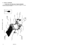
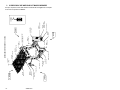
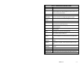
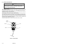
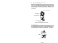
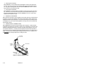
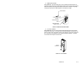
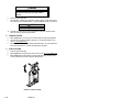
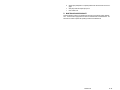
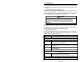
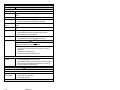
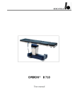
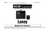
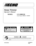
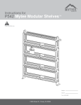
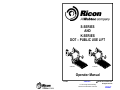
S-SERIES AND K-SERIES DOT – PUBLIC USE LIFT S-Series K-Series Operator Manual 01/24/08 32DSKL01.B ©2008 RICON CORPORATION All Rights Reserved U.S. and Foreign Patents Pending Printed in the United States of America PRINT THIS RICON PRODUCT MUST BE SERVICED BY AUTHORIZED RICON SERVICE TECHNICIANS. PRODUCT USERS MUST REFER TO THIS MANUAL FOR OPERATING AND GENERAL MAINTENANCE INSTRUCTIONS. RETAIN THIS MANUAL IN THE VEHICLE FOR FUTURE REFERENCE. “DOT – Public Use Lift” verifies that this platform lift meets the public use lift requirements of FMVSS no. 403. This lift may be installed on all vehicles appropriate for the size and weight of the lift, but must be installed on buses, school buses, and multi-purpose passenger vehicles other than motor homes with a gross vehicle weight rating (GVWR) that exceeds 10,000 lbs (4,536 kgs). Customer Information Customer name Installing dealer Date installed Serial number 32DSKL01.B -i- REVISION RECORD REVISION PAGES DESCRIPTION OF CHANGE ECR/ECO Cover S&K Series graphic. 32DSKL01. B 01/24/08 1-1 S&K Series Intro figure revised. 1-4 Figure 1-1. Revised S-Series Lift. 1-8 Figure 1-2. Revised K-Series Lift. 2-4 Figure 2-5. Revised Control Pendant. 3-3 Figure 3-1. Revised S-Series Lift for Decal Locations. 3-4 Figure 3-2. Revised K-Series Lift for Decal Locations. END OF TABLE - ii - 32DSKL01.B 600025 TABLE OF CONTENTS Chapter I. Page INTRODUCTION ........................................................................................................ 1-1 A. PRODUCT SUPPORT ....................................................................................... 1-1 B. PRODUCT WARRANTY .................................................................................... 1-2 C. SHIPMENT INFORMATION ............................................................................... 1-3 D. GENERAL SAFETY PRECAUTIONS ................................................................ 1-3 E. MAJOR LIFT COMPONENTS ............................................................................ 1-4 II. OPERATING INSTRUCTIONS .................................................................................. 2-1 A. B. C. D. E. F. G. SAFETY PRECAUTIONS .................................................................................. 2-1 DAILY SAFETY CHECK .................................................................................... 2-2 PLATFORM MOTIONS ...................................................................................... 2-3 CONTROLS AND INDICATORS ........................................................................ 2-4 • CONTROL PENDANT ................................................................................ 2-4 • CIRCUIT BREAKERS AND LED STATUS INDICATORS.......................... 2-5 • BRIDGEPLATE LOAD SENSOR ............................................................... 2-6 • THRESHOLD SAFETY SYSTEM............................................................... 2-6 • MANUAL BACK-UP PUMP ........................................................................ 2-7 • LIFT CYCLE COUNTER ............................................................................ 2-7 NORMAL LIFT OPERATION ............................................................................. 2-8 1. ENTERING VEHICLE................................................................................. 2-8 2. EXITING VEHICLE ..................................................................................... 2-9 3. STOWING PLATFORM .............................................................................. 2-9 MANUAL OPERATION .................................................................................... 2-10 1. DEPLOY PLATFORM .............................................................................. 2-10 2. LOWER PLATFORM ................................................................................ 2-12 3. STOW PLATFORM .................................................................................. 2-12 MAINTENANCE AND REPAIR NOTE ............................................................. 2-13 III. MAINTENANCE .............................................................................................. 3-1 A. B. C. D. ADDITIONAL MAINTENANCE INFORMATION ................................................. 3-1 CLEANING ......................................................................................................... 3-1 MAINTENANCE SCHEDULE ............................................................................. 3-1 DECAL PART NUMBERS AND LOCATIONS.................................................... 3-3 32DSKL01.B - iii - This page intentionally left blank. - iv - 32DSKL01.B I. INTRODUCTION T he Ricon S-Series and K-Series Public Use wheelchair lifts provide wheelchair access to public use vehicles including buses, school buses and large multi-purpose vehicles, and are DOT compliant. The platform on both S- and K-Series Public Use wheelchair lifts has a rated load capacity of 800 pounds, (364) kilograms. S-Series K-Series The S-Series has a solid, one-piece platform that is raised and folded into the vehicle when stowed. The platform on the K-Series splits horizontally to reduce overall lift height when stowed. This results in a less obstructed view, either into or out of the vehicle. The mechanical linkages provide smooth movement to both non-skid platforms where the wheelchair and occupant are situated during the “Up” and “Down” lift motions. S- and K-Series Public Use wheelchair lifts contain an electro-hydraulic pump with a built-in manual backup pump. If the lift loses power, it can be raised or lowered manually. Trained personnel operate the lift by using a control pendant. The control pendant is used to unfold the platform out from the vehicle (deploy). The passenger boards the non-skid platform and an operator lowers the platform to the ground. After the passenger departs, the platform is stowed back into the vehicle. This manual contains warranty information, safety precautions, operating and maintenance instructions that apply to both Ricon S- and K-Series Public Use wheelchair lifts. It is important to user safety that the lift operator be completely familiar with the operating instructions. Once the lift is installed, it is very important that the lift be properly maintained by following the Ricon recommended maintenance and inspection instructions provided in Chapter III. A. PRODUCT SUPPORT If there are questions about this manual, or you need copies, please contact Ricon Product Support at the following location: Ricon Corporation 7900 Nelson Road Panorama City, CA 91402 .................................................................................(818) 267-3000 Outside (818) Area Code: .................................................................................(800) 322-2884 World Wide Website: .............................................................................. www.RiconCorp.com 32DSKL01.B 1-1 B. PRODUCT WARRANTY RICON CORPORATION S- SERIES AND K-SERIES PUBLIC USE WHEELCHAIR LIFTS FIVE-YEAR LIMITED WARRANTY Ricon Corporation (Ricon) warrants to the original purchaser of this product that Ricon will repair or replace, at its option, any parts that fail because of defective material or workmanship as follows: y y y Repair or replace parts for a period of one year from the date of purchase. A complete list of parts covered by this warranty can be obtained from Ricon Corporation. Labor cost for a period of one year from the date of purchase. A Ricon rate schedule determines parts covered and labor allowed. Repair or replace lift powertrain parts for a period of five years from date of purchase. A complete list of parts covered can be obtained from Ricon Corporation. If You Need to Return a Product: Return this product to Ricon, following the Ricon RMA procedure. Please give as much advance notice as possible, and allow a reasonable amount of time for repair. This Warranty Does Not Cover: y Malfunction or damage to product parts caused by accident, misuse, lack of proper maintenance, neglect, improper adjustment, modification, alteration, the mechanical condition of the vehicle, road hazards, overloading, failure to follow operating instructions, or acts of nature (i.e., weather, lightning, flood). NOTE: Ricon recommends that this product be inspected by an authorized Ricon service technician at least once every six months, or sooner if necessary. Required maintenance should be performed at that time. WARNING THIS PRODUCT HAS BEEN DESIGNED AND MANUFACTURED TO EXACT SPECIFICATIONS. ~ ANY MODIFICATION OF THIS PRODUCT CAN BE HAZARDOUS ~ This Warranty is Void If: y y The product has been installed or maintained by someone other than an authorized Ricon service technician. The product has been modified or altered in any respect from its original design without written authorization by Ricon. Ricon disclaims liability for any personal injury or property damage that results from operation of a Ricon product that has been modified from the original Ricon design. No person or company is authorized to change the design of this Ricon product without written authorization by Ricon. Ricon's obligation under this warranty is exclusively limited to the repair or exchange of parts that fail within the applicable warranty period and the authorized labor to accomplish said repair. Ricon assumes no responsibility for expenses or damages, including incidental or consequential damages. Some states do not allow the exclusion or limitation of incidental or consequential damages, so the above limitation or exclusion may not apply. Important: The warranty registration card must be completed and returned to Ricon within 20 days after installation of this Ricon product for the warranty to be valid. The warranty is not transferable. The warranty gives specific legal rights. There may be other rights that vary in each state. 1-2 32DSKL01.B C. SHIPMENT INFORMATION When the product is received, unpack the product and check for freight damage. Claims for damage should be made to the freight carrier immediately. Be sure the installation kit contains all items listed on the kit packing list. Please report any missing items immediately to Ricon Product Support. The warranty and owner registration cards must be completed and returned to Ricon within 20 days to validate the warranty. The sales or service personnel must review the Warranty and Operator Manual with the user to be certain that they understand how to safely operate the product and instruct the user to follow the operating instructions without exception. D. GENERAL SAFETY PRECAUTIONS The following safety precautions apply to both S-Series and K-Series Public Use wheelchair lifts and must be followed during operation and maintenance: Read and thoroughly understand the operating instructions before attempting to operate the lift. Inspect product before each use. If unsafe conditions, unusual noises or movements, do not operate lift until the problem is corrected. Exercise caution when operating lift to avoid injury, and be certain that hands, feet, legs or clothing are not in the path of product movement. Stand clear of doors and platform and keep others clear during operation. The lift requires regular periodic maintenance. A thorough inspection is recommended at least once every six months. The product should be maintained at the highest level of performance. 32DSKL01.B 1-3 MAJOR LIFT COMPONENTS 1. S-SERIES PUBLIC USE WHEELCHAIR LIFT MAJOR COMPONENTS E. The major components of the S-Series Public Use wheelchair lift are in Figure 1-1. A description of each of the components is in Table 1-1. MANUAL BACKUP PUMP HANDLE (INSIDE) REAR CYCLE COUNTER VISUAL ALARM HYDRAULIC CYLINDER THRESHOLD BEAM BASEPLATE PLATFORM LIGHT BRIDGEPLATE (INBOARD ROLLSTOP) LEFT HYDRAULIC POWER UNIT AUDIBLE ALARM (INSIDE) CONTROL PENDANT HANDRAIL VERTICAL ARM TOP AND BOTTOM ARMS STOW-LOCK CATCH SERIAL NUMBER BRIDGEPLATE LOAD SENSOR PLATFORM FRONT ROLLSTOP FIGURE 1-1: S-SERIES MAJOR COMPONENTS RIGHT OCCUPANT RESTRAINT BELT FRONT 32DSKL01.B 1-4 TABLE 1-1: S-SERIES MAJOR COMPONENT TERMS TERM DESCRIPTION Left, right, front, rear Position references when installed lift is viewed from outside of vehicle. Audible alarm (inside housing of hydraulic unit) Announces when something passes through the threshold area while the lift platform is below floor level. The alarm is activated by threshold beams. Baseplate Bolts to vehicle floor; provides secure foundation for lift structure. Bridgeplate (inboard rollstop) Plate that bridges gap between platform and baseplate when platform is at floor level. Also acts as a rear rollstop when platform is in motion. Bridgeplate load sensor Senses if weight is present on the lowered bridgeplate. Control pendant Hand-held device used to control platform motions. Cycle counter Visible at top rear of housing, it records number of times platform has moved from floor to ground and back to floor. Platform Component of lift where the wheelchair and occupant are situated during “UP” and “DOWN” lift motions. Front rollstop Front barrier prevents wheelchair from inadvertently rolling off of platform during platform movement. Handrail (left and right) Provides handhold for standing passenger. Hydraulic cylinder (left and right) Telescoping single-acting cylinders convert hydraulic pressure into platform lifting and folding force. Hydraulic power unit Contains hydraulic pump driven by electric motor that produces pressure to raise and fold platform, and a pressure release valve to unfold and lower it. Manual backup pump handle (located inside housing of hydraulic unit) Used to operate manual back up-pump. Occupant restraint belt Electrically interlocked safety belt that is intended to prevent acceleration of wheelchair while on the platform. Lift will not operate unless belt is securely fastened. Platform light (left and right) Directs light onto platform surface. Serial number Location of lift serial number decal. Stow-Lock catch Engages latch located on bottom of bridgeplate when platform is fully stowed. Threshold beams Light-beams detect something passing through the threshold area while platform is below floor level. CONTINUED 32DSKL01.B 1-5 TABLE 1-1: S-SERIES MAJOR COMPONENT TERMS TERM DESCRIPTION Top and bottom arms (left and right) Upper and lower links that connect vertical arms to baseplate. Vertical arm (left and right) Connects platform to top and bottom arms. Visual alarm Flashing light makes it known when something passes through threshold area. Activated by threshold beams. END OF TABLE 1-6 32DSKL01.B This page intentionally left blank. 32DSKL01.B 1-7 The major components of the K-Series Public Use wheelchair lift are in Figure 1-2. A description of each of the components is in Table 1-2. VISUAL ALARM REAR THRESHOLD BEAM BASEPLATE HYDRAULIC CYLINDER RIGHT OCCUPANT RESTRAINT BELT FRONT PLATFORM HINGES PLATFORM FOLDING LINKAGE HANDRAIL VERTICAL ARM TOP AND BOTTOM ARMS STOW-LOCK CATCH SERIAL NUMBER BRIDGEPLATE LOAD SENSOR FRONT ROLLSTOP FRONT PLATFORM SECTION REAR PLATFORM SECTION PLATFORM LIGHT BRIDGEPLATE (INBOARD ROLLSTOP) CYCLE COUNTER LEFT HYDRAULIC POWER UNIT AUDIBLE ALARM (INSIDE) MANUAL BACKUP PUMP HANDLE (INSIDE) CONTROL PENDANT FIGURE 1-2: K-SERIES MAJOR COMPONENTS 32DSKL01.B 1-8 K-SERIES PUBLIC USE WHEELCHAIR LIFT MAJOR COMPONENTS 2. TABLE 1-2: K-SERIES MAJOR COMPONENT TERMS TERM DESCRIPTION Left, right, front, rear Position references when installed lift is viewed from outside of vehicle. Audible alarm (inside housing of hydraulic unit) Announces when something passes through the threshold area while the lift platform is below floor level. The alarm is activated by threshold beam. Baseplate Bolts to vehicle floor; provides secure foundation for lift structure. Bridgeplate (inboard rollstop) Plate that bridges gap between platform and baseplate when platform is at floor level. Also acts as a rear rollstop when platform is in motion. Bridgeplate load sensor Senses if weight is present on the lowered bridgeplate. Control pendant Hand-held device used to control platform motions. Cycle counter Visible at top rear of housing, it records number of times platform has moved from floor to ground and back to floor. Front platform section Front portion of platform that unfolds during deploy and folds during stow. See “Platform folding linkage”. Front rollstop Front barrier prevents wheelchair from inadvertently rolling off of platform during platform movement. Handrail (left and right) Provides handhold for standing passenger. Hydraulic cylinder (left and right) Telescoping single-acting cylinders convert hydraulic pressure into platform lifting and folding force. Hydraulic power unit Contains hydraulic pump driven by electric motor that produces pressure to raise and fold platform, and a pressure release valve to unfold and lower it. Manual backup pump handle (located inside housing of hydraulic unit) Used to operate manual back up-pump. Occupant restraint belt Electrically interlocked safety belt that is intended to prevent acceleration of wheelchair while on the platform. Lift will not operate unless belt is securely fastened. Platform folding linkage (left and right) Links that cause front platform section to unfold as it deploys or fold as it stows. Platform hinges Three hinges provide connection between front and rear platform sections. Platform light (left and right) Directs light onto platform surface. Rear platform section Rear portion of platform that is folded by linkage located within the vertical arms. CONTINUED 32DSKL01.B 1-9 TABLE 1-2: K-SERIES MAJOR COMPONENT TERMS TERM DESCRIPTION Serial number Location of lift serial number decal. Stow-Lock catch Engages latch located on bottom of bridgeplate when platform is fully stowed. Threshold beams Light-beams detect something passing through the threshold area while platform is below floor level. Top and bottom arms (left and right) Upper and lower links that connect vertical arms to baseplate. Vertical arm (left and right) Connects platform to top and bottom arms. Visual alarm Flashing light makes it known when something passes through threshold area. Activated by threshold beams. END OF TABLE 1 - 10 32DSKL01.B II. OPERATING INSTRUCTIONS T his chapter contains safety precautions, daily safety check instructions, control and indicator descriptions, and operating instructions that apply to RICON S-Series and K-Series Public Use wheelchair lifts. This chapter must be thoroughly understood by the operator before using lift. A. SAFETY PRECAUTIONS The following safety precautions must be complied with at all times when operating lift: Refer to Figure 2-1. Deploying lift when vehicle is on sloped ground is hazardous. Operate lift with vehicle parked on level ground. FIGURE 2-1: SLOPED PARKING HAZARD Vehicle must be safely parked with parking brake ON before using lift. Inspect lift before use. Do not use lift if any unsafe condition exists, or unusual noises or movements are noticed, and contact an authorized Ricon service technician for repair. Read and comply with all warning labels and symbols affixed to wheelchair lift. Refer to Figure 2-2. Wheelchair occupant should face outward on platform when entering or exiting vehicle to minimize the possibility of the large rear wheels rolling up and over the front rollstop. FIGURE 2-2: EXITING BACKWARDS IS HAZARDOUS Do not rely on a threshold-warning device (audible, or other) to confirm that it is safe for a passenger to exit backwards. This device may be inoperative or unheard, and they might exit backwards when the platform is on the ground! When exiting vehicle, verify that platform is at same height as floor and front rollstop is up and locked. Do not place equipment or furniture inside vehicle that may prevent pivoting of your wheelchair. Being able to pivot assures that you can safely exit facing outward. Be certain wheelchair fits safely on platform; it must not extend beyond edges or interfere with operation of rollstop. 32DSKL01.B 2-1 The raised front rollstop prevents slow and unintentional rolling off of the platform. It is not intended to stop a fast-moving wheelchair, which might tip forward if the small front wheels collide with the rollstop. Do not operate with a load in excess of 800 lbs (364 kgs). Keep arms, legs, and clothing away from moving lift parts. The lift is intended for one wheelchair and its occupant or one standee. Do not overload lift. Refer to Figure 2-3. Do not stand in front of lift while deploying platform. FIGURE 2-3: STAND CLEAR OF LIFT Keep others clear while operating lift. Do not allow an untrained person to operate lift. Careful supervision is necessary if used near children. Do not allow anyone to stand on bridgeplate. A bent bridgeplate can interfere with the platform as it raises and lowers. Lock wheelchair brakes before moving platform (power chair users should turn off power and set brake). Use great care in wet conditions, because the wheelchair brakes are less effective if wheels or platform are wet. Never leave platform outside of vehicle. Return platform to stowed position after use. Do not load an oversize wheelchair into vehicle if it is too large to pivot freely inside vehicle. Read and understand these safety precautions. Review them periodically and ask other operators to read them as well. Contact an authorized Ricon service technician or call Ricon Product Support if there are questions. B. DAILY SAFETY CHECK Inspect lift before use and meet the following conditions: All functions operate properly. Do not use lift if unusual noises or movements exist, and contact an authorized Ricon service technician for repair. Vehicle interlock is operating properly. Objects that may interfere with operation are not present. General appearance and lubrication are satisfactory and fasteners are tight. 2-2 32DSKL01.B C. PLATFORM MOTIONS TABLE 2-1: PLATFORM MOTIONS MOVEMENT S-Series DESCRIPTION K-Series D E P L O Y Platform unfolds, or deploys, out of vehicle from stowed position to floor level position. If equipped with a power door operator, the doors automatically open before lift deploys. D O W N Platform lowers from vehicle floor level towards ground level. The front rollstop automatically lowers (opens) when platform reaches ground level. U P Platform rises from ground level towards vehicle floor level. The front rollstop automatically rises (closes) when platform leaves ground level. S T O W Platform folds, or stows, from vehicle floor level to the stowed position. If equipped with a power door operator, the doors automatically close after lift stows. END OF TABLE NOTE: The up and down functions do not operate if platform is in stowed position. STOWED POSITION NOTE: HANDRAILS AND PINCH POINT SHIELDS REMOVED FOR CLARITY. VEHICLE FLOOR LEVEL GROUND LEVEL FIGURE 2-4: PLATFORM POSITIONS 32DSKL01.B 2-3 D. CONTROLS AND INDICATORS WARNING THE LIFT CAN OPERATE ONLY WHEN THE VEHICLE MANUFACTURER INTERLOCK CIRCUITRY IS ACTIVATED. IF NECESSARY, REFER TO VEHICLE OPERATOR MANUAL FOR INTERLOCK INSTRUCTIONS. DO NOT ATTEMPT TO OPERATE LIFT WITH INTERLOCK BYPASSED. CONTROL PENDANT Refer to Figure 2-5. The lift is operated with four rocker switches and an ON-OFF switch located on the hand-held, hard-wired remote-control pendant. Turn on the POWER switch and then press an appropriate rocker switch to control each lift motion. The POWER switch enables the pendant by providing power to it and must be turned on before the lift can be operated. When turned on, the power switch will illuminate. Pressing the DEPLOY rocker switch unfolds the platform from the vehicle, and pressing the STOW rocker switch folds the platform back into the vehicle. Pressing the DOWN rocker switch lowers the platform towards the ground, and pressing the UP rocker switch raises the platform towards the floor. A rocker switch must be held depressed until the motion is completed. Movement of the platform can be halted at any time by releasing the rocker switch. The pendant is typically stowed on a wall-mounted clip inside the vehicle, near the lift. POWER ENABLE DEPLOY STOW DOWN UP FIGURE 2-5: CONTROL PENDANT 2-4 32DSKL01.B y CIRCUIT BREAKERS AND LED STATUS INDICATORS Pump Solenoid LED Status Indicators Refer to Figure 2-6. The pump has two solenoids that provide a margin of safety if one of them fails with its contacts closed. Green and red LED status indicators monitor the condition of the two solenoids, and are located between two 8A circuit breakers. The green LED is normally off when the pump is not operating and will illuminate when the pump operates. When the pump is not operating and the second solenoid has failed the red LED will illuminate. The green LED will illuminate if the first solenoid has failed. For more information on both indicator lights refer to Service manual 32DSKL02. LED STATUS INDICATORS 8 AMP HANDRAIL LIGHTS CIRCUIT BREAKER 8 AMP CONTROL SYSTEM CIRCUIT BREAKER 2ND SOLENOID 1ST SOLENOID FIGURE 2-6: PUMP SOLENOIDS LED STATUS INDICATORS y Main Circuit Breaker Refer to Figure 2-7. The main circuit breaker is located in the vehicle engine compartment and is used to interrupt electrical power to the lift electrical system when a major short circuit occurs. In such event, the circuit breaker reset tab will “flip-down”. If pressing reset tab back up (as shown by arrow) and releasing it does not reset power, do not press and hold tab. Contact a Ricon authorized service technician for repair. RESET TAB FIGURE 2-7: MAIN CIRCUIT BREAKER 32DSKL01.B 2-5 y Handrail Lights Circuit Breaker Refer to Figure 2-6. The circuit breaker for the handrail lights is located on the hydraulic pump assembly. In the event of a short circuit in the handrail lights, the circuit breaker button will “popout”. If pressing and releasing button does not reset power, DO NOT press and hold. Contact a Ricon authorized service technician for repair. y Control System Circuit Breaker Refer to Figure 2-6. The Control System Circuit Breaker is located on the hydraulic pump assembly. In the event of a short circuit in the control system, the circuit breaker button will “pop-out”. If pressing and releasing button does not reset power, DO NOT press and hold. Contact a Ricon authorized service technician for repair. BRIDGEPLATE LOAD SENSOR Refer to “Major Lift Components” section in Chapter I for the location of the sensor switch that detects the presence of a load on the bridgeplate. When the sensor detects that an object is present on the bridgeplate it inhibits lowering of the platform. This protects the passenger from possible injury when the bridgeplate rises, and also protects the bridgeplate from damage, which could later interfere with proper operation of the lift. THRESHOLD SAFETY WARNING SYSTEM Refer to Figure 2-8 for the location of threshold warning system components. The lift incorporates two light beams that detect when a passenger (or object, such as a wheelchair) is in the vicinity of the baseplate or bridgeplate (threshold area). The beams are enabled when the platform is one inch, or more, below the vehicle floor. If someone passes through either of the beams when the platform is one inch below the floor an audible alarm and flashing red light are actuated. This system provides a margin of safety for lift users by warning them if the platform is below floor level. The platform must be at floor level when boarding the platform prior to exiting the vehicle. FLASHING RED LIGHT AUDIBLE ALARM (INSIDE) LIGHT BEAMS APPROXIMATE THRESHOLD AREA FIGURE 2-8: THRESHOLD WARNING SYSTEM 2-6 32DSKL01.B MANUAL BACK-UP PUMP Refer to Figure 2-9. The manual backup pump is used to operate the lift if electrical power is not functioning. Controls for the pump are located inside housing of hydraulic unit and consist of a pump handle to raise platform, and a pump pressure release valve to lower it. Instructions for operating manual pump are provided in the “Manual Operation” section later in this chapter. PUMP HANDLE PUMP HANDLE SOCKET MANUAL BACKUP PUMP PUMP PRESSURE RELIEF VALVE FIGURE 2-9: MANUAL BACKUP PUMP & HANDLE LIFT CYCLE COUNTER Refer to Figure 2-10. The cycle counter is located inside the hydraulic pump housing and visible through a slot on the rear side. The counter advances each time the platform moves through a complete cycle, which consists of the platform moving from the vehicle floor to the ground and back to the floor. The number of cycles displayed is used to schedule maintenance operations. For maintenance schedule refer to Chapter III of this document. CYCLE COUNTER FIGURE 2-10: CYCLE COUNTER 32DSKL01.B 2-7 E. NORMAL LIFT OPERATION WARNING IMPROPER USE OF LIFT CAN RESULT IN PERSONAL INJURY. USERS MUST READ AND FOLLOW OPERATING INSTRUCTIONS. ADDITIONAL COPIES OF OPERATOR MANUAL ARE AVAILABLE FROM: RICON CORPORATION 7900 NELSON ROAD PANORAMA CITY, CA 91402 (800) 322-2884 or (818) 267-3000 DO NOT EXCEED RATED LOAD CAPACITY OF 800 POUNDS (364 KGS). PRIOR TO USE, INSPECT WHEELCHAIR LIFT FOR PROPER FUNCTION, REQUIRED MAINTENANCE, OR DAMAGE. IF A PROBLEM EXISTS, DO NOT USE LIFT AND CONTACT A RICON AUTHORIZED SERVICE TECHNICIAN FOR REPAIR. THIS LIFT IS FOR USE BY WHEELCHAIR OCCUPANTS AND STANDEES. RICON CORPORATION DISCLAIMS LIABILITY FOR DAMAGE OR PERSONAL INJURY RESULTING FROM MODIFICATION TO LIFT, LACK OF MAINTENANCE OR REPAIR, NEGLIGENCE, ABUSE, OR FAILURE TO FOLLOW LIFT OPERATING INSTRUCTIONS. Before operating lift, be certain vehicle is safely parked on a level area away from traffic. Provide space for lift operation and passenger boarding. The lift operator must take special care to be certain that area is clear before deploying lift. Be certain there are no obstacles beneath platform. Open doors completely if lift is not equipped with a power door operator. If so equipped, the vehicle doors will automatically open before platform deploys and close after platform is stowed. If equipped with a safety interlock mechanism (e.g. transmission, parking brake, etc) be certain that it is properly engaged before attempting to operate lift. The lift will not operate until this feature has been engaged properly. A person that uses the wheelchair lift while standing (does not require mobility aid equipment) is referred to in this manual as a Standee. WARNING ATTENDANT MUST REMAIN NEAR PASSENGER TO RENDER IMMEDIATE ASSISTANCE WHEN NECESSARY. 1. ENTERING VEHICLE: NOTE: The occupant restraint belt must be fastened to enable the DEPLOY, DOWN, UP, and STOW motions; the platform will not operate unless this safety mechanism is connected. Turn the pendant power switch on. a. b. 2-8 DEPLOY PLATFORM - Push and hold DEPLOY rocker switch until platform is completely unfolded from vehicle and stops at floor level. LOWER PLATFORM - Push and hold DOWN rocker switch until platform is at ground level and front rollstop is fully lowered. 32DSKL01.B c. Unfasten occupant restraint belt, carefully place wheelchair in center of platform, preferably facing outward (away from vehicle), and lock wheelchair brakes. If a power wheelchair is used, turn power off. CAUTION Be certain wheelchair is clearly within perimeter of platform and does not interfere with operation of rollstop. Ù d. e. f. g. 2. A Standee must stand near the center of the platform, facing in the direction of travel (into vehicle), and firmly grasp handrails. Fasten occupant restraint belt. RAISE PLATFORM - Push and hold UP rocker switch until platform rises and stops automatically at floor level. Release wheelchair brakes. If a power wheelchair is used, turn power back on. Carefully board passenger into vehicle, and secure wheelchair. Refer to “Stowing Platform” section below to stow platform. EXITING VEHICLE: NOTE: The occupant restraint belt must be fastened to enable the DEPLOY and DOWN motions. The platform will not operate unless this safety mechanism is connected. Turn the pendant power switch on. a. DEPLOY PLATFORM - Push and hold DEPLOY rocker switch until platform is completely unfolded from vehicle and stops at floor level. WARNING VERIFY THAT PLATFORM IS AT VEHICLE FLOOR LEVEL AND THAT FRONT ROLLSTOP IS UP AND LOCKED IN POSITION. b. c. Fasten occupant restraint belt. Carefully place wheelchair in center of platform, preferably facing outward (away from vehicle), and lock wheelchair brakes. If a power wheelchair is used, turn power off. CAUTION Do not stand on bridgeplate as platform lowers. Ù d. e. f. 3. A Standee must stand near the center of the platform, facing in the direction of travel (away from vehicle), and firmly grasp handrails. LOWER PLATFORM - Push and hold DOWN rocker switch until platform is at ground level and front rollstop is fully lowered. Unfasten occupant restraint belt and release wheelchair brakes. If a power wheelchair is used, turn power back on. Carefully assist passenger off platform. Refer to “Stowing Platform” section on next page to stow platform. STOWING PLATFORM: NOTE: The occupant restraint belt must be fastened to enable the UP and STOW motions. The platform will not operate unless this safety mechanism is connected. 32DSKL01.B 2-9 NOTE: If platform is at ground level, push and hold UP rocker switch until platform rises and stops automatically at floor level. g. Push and hold STOW rocker switch until platform folds completely into vehicle. CAUTION Verify that platform has folded completely before closing doors. To avoid damage to doors, do not release switch until lift has folded completely and lift pump motor has stopped automatically. h. F. Close vehicle doors if lift is not equipped with a power door operator. If so equipped, the vehicle doors may close automatically after platform is stowed. MANUAL OPERATION The lift can be operated manually if the lift electrical power source is absent. Ricon recommends that manual operation be used only for exiting passengers from vehicle. Preparation: Be certain vehicle is on a level area and away from traffic. Allow space for platform movement plus space to exit from platform. The vehicle operator must summon assistance to move vehicle to a safe area if a break down situation exists where vehicle cannot be moved under its own power. Open doors manually if vehicle is not equipped with a power door operator. If equipped with a power door operator, refer to its operator manual for manual operation directions. WARNING FOLLOW PRECAUTIONS IN “LIFT OPERATION” SECTION WHEN USING MANUAL BACKUP SYSTEM TO ENTER OR EXIT VEHICLE. NOTE: The threshold warning system is not active during manual operation and cannot be used to indicate platform height. 1. DEPLOY PLATFORM a. Refer to Figure 2-11. Override the Stow-Lock feature by lifting bridgeplate by hand. This will separate the Stow-Lock catch (fastened to underside of bridgeplate) from Stow-Lock latch (fastened to baseplate). If Stow-Lock is difficult to separate, use manual backup pump to raise platform slightly to remove tension from catch; refer to “Stowing Platform” paragraph in this section. STOW-LOCK CATCH RELEASE FIGURE 2-11: RAISE BRIDGEPLATE 2 - 10 32DSKL01.B b. Refer to Figure 2-12. Remove hydraulic unit cover to locate pump handle. Insert notched end of pump handle into shaft with roll pin crossing on hydraulic pump unit and engage pump release valve while holding bridgeplate. Once platform starts to deploy, release bridgeplate. PUMP HANDLE NOTCHED END SHAFT WITH ROLL PIN CROSSING FIGURE 2-12: OPEN RELEASE VALVE CAUTION Do not open pump release valve more than ¼-turn. Opening valve further may cause it to completely disengage from pump body, which will disable its pumping ability. c. d. Refer to Figure 2-12. Turn valve 1/4 turn counter-clockwise to begin lowering platform. Refer to Figure 2-13. When platform reaches level of interior floor turn valve clockwise to close; do not over-tighten valve. Do not lower platform below vehicle floor level. The rear edge of bridgeplate must rest flat on vehicle floor. FIGURE 2-13: CLOSE RELEASE VALVE 32DSKL01.B 2 - 11 WARNING VERIFY THAT PLATFORM IS AT VEHICLE FLOOR LEVEL AND THAT FRONT ROLLSTOP IS UP AND LOCKED IN POSITION. e. f. Fasten occupant restraint belt. Load passenger. Carefully place wheelchair in center of platform, facing outward (away from vehicle), and lock wheelchair brakes. If a power wheelchair is used, turn power off. CAUTION Do not stand on bridgeplate as platform lowers. Ù 2. A Standee must stand near the center of the platform, facing in the direction of travel (away from vehicle), and firmly grasp handrails. LOWER PLATFORM a. b. c. 3. Refer to Figure 2-12. Turn valve 1/4 turn counter-clockwise to begin lowering platform. Hold valve open until platform settles at ground level. Turn handle clockwise to close valve; do not over-tighten valve. Unfasten occupant restraint belt and release wheelchair brakes. If a power wheelchair is used, turn the power back on. Carefully assist passenger off platform. STOW PLATFORM a. b. c. Fasten occupant restraint belt. Refer to Figure 2-12. Verify that pump release valve is closed; do not over-tighten valve. Refer to Figure 2-14. Insert notched end of pump handle into pump shaft with roll pin crossing. Operate pump to begin raising and folding platform. FIGURE 2-14: RAISE PLATFORM 2 - 12 32DSKL01.B d. e. f. Operate pump until platform is completely folded inside vehicle and Stow-Lock has engaged. Stow pump handle and replace pump cover. Close vehicle doors. G. MAINTENANCE AND REPAIR NOTE Follow the lubrication, cleaning, and maintenance instructions in the following chapter, “Maintenance”. These instructions apply to Ricon S-Series and K-Series Public Use wheelchair lifts. The instructions are meant to optimize the operating condition of the wheelchair lift. 32DSKL01.B 2 - 13 This page intentionally left blank. 2 - 14 32DSKL01.B III. MAINTENANCE T his chapter contains cleaning instructions, a maintenance schedule, and decal information that applies to RICON S-Series and K-Series Public Use wheelchair lifts. Regular maintenance of the RICON S- and K-Series Public Use wheelchair lifts will provide optimum performance and reduce the need for repairs. A. ADDITIONAL MAINTENANCE INFORMATION Additional maintenance information is available in the RICON S-Series and K-Series Public Use service manual, part number 32DSKL02. This manual is available from Ricon in printed hard copy, or at the Ricon website in PDF format. The website is located at www.RiconCorp.com. At the website, click on “Technical Documents”, “I agree”, and then “Service Manuals”. WARNING THIS RICON PRODUCT IS HIGHLY SPECIALIZED. MAINTENANCE AND REPAIRS MUST BE PERFORMED BY A RICON AUTHORIZED SERVICE TECHNICIAN USING RICON REPLACEMENT PARTS. MODIFYING OR FAILING TO PROPERLY MAINTAIN THIS PRODUCT WILL VOID THE WARRANTY, AND MAY RESULT IN UNSAFE OPERATING CONDITIONS. B. CLEANING Regular cleaning with mild soap (i.e. liquid hand soap or car wash liquid) and drying thoroughly will protect lift painted surfaces. Cleaning is especially important in areas where roads are salted in winter. Make sure that lift pivot points are clean and dry prior to lubrication. C. MAINTENANCE SCHEDULE Refer to cycle counter located on rear side of hydraulic power unit. Under normal operating conditions, maintenance inspections are required at the frequencies listed in Table 3-1. Ten cycles is considered an average number of cycles for one day. TABLE 3-1: MAINTENANCE SCHEDULE SERVICE POINT ACTION TO PERFORM 10 CYCLES Overall condition Listen for abnormal noises as lift operates (i.e. grinding or binding noises.) Control pendant Verify that control pendant is undamaged and cable connector is tight. Verify that switch and buttons are illuminated. Threshold warning system Verify that system properly detects objects in baseplate area and actuates the visual and audible alarms. Bridgeplate load sensor Verify that sensor inhibits downward movement of platform when a weight is present on lowered bridgeplate. Platform lights Verify that both lights are on when lift is powered. 150 CYCLES Overall condition Listen for abnormal noises as lift operates (i.e. grinding or binding noises). Inspect underside of vehicle for anything that is out of place. Electrical wiring Inspect electrical wiring for frayed wires, loose connectors, etc. CONTINUED 32DSKL01.B 3-1 TABLE 3-1: MAINTENANCE SCHEDULE SERVICE POINT ACTION TO PERFORM 150 CYCLES (CONT.) Vehicle interlock Place vehicle in non-interlock mode and verify that lift does not operate. Decals Verify that lift decals are properly affixed, clearly visible, and legible. Replace, if necessary. Verify that handrail fasteners are properly tightened. Verify that vehicle mounting and support points are undamaged. Verify that mounting bolts are sufficiently tight and corrosion free. Handrails Lift mounting points Main lifting pivots Platform pivot points Bridgeplate Front rollstop Verify that link pins on arms are properly installed, free from damage, and locked in position. Verify that platform moves freely, without binding, and does not wobble. (If applicable) Verify that bridgeplate operates without binding during lift functions. Verify that bridgeplate deploys fully when platform stops at floor level. Verify bridgeplate rests flat against baseplate. Verify that rollstop is opened completely when platform is at ground level. Verify that rollstop closes and locks when platform leaves ground. Hydraulic power unit CAUTION Check and add fluid when platform is at ground level. Fluid that is added when platform is raised will overflow when platform is lowered. Verify that pump hydraulic fluid level is at FULL mark when platform is at ground level. Add Texaco 01554 Aircraft Hydraulic Oil or equivalent U.S. mil spec H5606G fluid. Verify there are no hydraulic fluid leaks. Verify that manual backup pump operates properly. 1800 CYCLES Cleaning and lubrication 1. Clean lift with mild soap and water and wipe dry. Prevent rust by coating all surfaces with a lightweight oil. Remove excess oil. 2. Spray penetrating oil (Curtisol® Red Grease 88167 or WD-40®) where specified in the service manual 32DSKL02 following directions on container. Remove excess grease from surrounding areas. CAUTION A Ricon authorized service technician must perform the annual safety check. 3600 CYCLES Hydraulic cylinder, hoses and fittings 3-2 Check hydraulic cylinder for evidence of leaks. Inspect hydraulic hoses for damage. Verify that all fittings are tight. END OF TABLE 32DSKL01.B D. DECAL PART NUMBERS AND LOCATIONS Inspect decals at intervals in Table 3-1. Inspect for chipping, peeling, fading, and illegibility. Order replacement decals with part number given in Figure 3-1 and Figure 3-2, and apply where shown. MANUAL OPERATION 1 2 3 CORPORATION 7900 N elson Road, Panorama City, CA 91402 mfg. date: DEPLOY Made in U.S.A. 1 - MAINTENANCE REQUIRED IF CONTINUOUSLY ILLUMINATED - MAINTENANCE DOIT ETRE FAITE SI CETTE LUMIERE RESTE ALLUMEE EN PERMANENCE - MATENIMIENTO ES REQUERIDO SI PERMANECE CONTINUAMENTE ILUMINADO - BEI UNUNTERBROCHENER WARNLICHT ANZEIGE IST WARTUNG ERFORDERLICH 36932.A PART OF SERIAL NUMBER DECAL (LOCATED ON INNER SIDE OF HYDRAULIC CYLINDER; ONLY RICON REPLACEABLE) 2 SECOND SOLENOID PN 36932 RAISE AND STOW 36929.B MANUAL OPERATION PN 36929 UP CUTOFF ADJUSTMENT SCREW DOWN CUTOFF ADJUSTMENT SCREW 36948.A LIMIT SWITCHES PN 36948 (INSIDE PUMP COVER) CORPORATION 7900 Nelson R oad, Panorama City, CA 91402 mfg. date: M ade in U.S.A. PART OF SERIAL NUMBER DECAL (ONLY RICON REPLACEABLE) PROPER LOADING PN 26201 U.S. and foreign patents pending. 32-10-171 US AND FOREIGN PATENTS PENDING P/N 32-10-171 I NP UTS D8 - DOOR CLOSE D - ON when door sar e closed (P rivat e Use models on yl ) D11 -DOOR OPEN OUTA - ON whe n d oors are fully open a nd DEPLOY penda nt switch si activated (P rivate Use mo dels on yl ) D12- GROUND SWITCH - OFF when lif t si mor e than 3 " ab ove ground le vel and rollstop iso pen D13- BRI DGEP LAT E SWITCH - ON wh en presence of a 25 lb or higher ol ad si dete cted on th e bridgeplate D14- P RES SURE SWITCH - OFF w hen platf orm is occupied D15- S TOWED SWITCH - ON when plat form is full y st owed (Private Use models only) D16- UP /S TOW SWITCH - ON when plat form is belo w f loor level D17- DE PL OY - ON when DEPL OY pen dant swit ch si a ct vi ated D18- DOWN - ON when DOWN penda nt switch si activated D19- UP - ON when UP pend ant switc h isactivated D20- BE LT ON wh en occup ant restr ain t belt issecurely fastened D21- DOWN/DE PL OY SWITCH - ON when plat form si fullystowed D22- S TOW - ON when S TOW penda nt switch si activat ed ( Pu blic Use m odels only) O UTP UTS D2 - DOOR CLOSE ON when send ing signa l to door operat or to close door (Private Use models only) D3 - S TOW LOCK - ON when stow-lo ck solenoid is act iva ted to release p al tform in order to deploy D4 - S LO- BLOC VALVE - ON when SLO-BLOC valve i sa ctivated to dep loy platform D5 - COUNT ER - ON when sending signal to counte r to cou nt one cycle D6 - RED L IGHT L ED si ON/ OFF ni ter mit tently wh en red light an d buzzard are activated Red li ght and buzzard are activat ed when th e following conditio nsar e met: -Platform si 1" below flo or level D OWN/ DE PLOY e nable Curr ent flow thr oug h norm all y OPEN switch conta cts. S TOW/do or clo se ena ble S witch states when platfo rm is beyon d normal tr ave l bo undaries. PL AT FORM ON GROUND F OL DED P LA TFORM AT FLOOR S WITCH Curr ent flow thr oug h norm all y CLOS ED switch conta cts. P LA TFORM -T hreshold Wa rning S ystem det ect ssome thing int erruptssensor bea ms D7 - P UMP - ON w hen pump si activa ted in ord er to ra ise or stow platform D9 -DOOR OP EN S DA - ON when a ttempting to op en do orswith door operator ( Private Use mod els o nly) D10 -DOWN V ALVE - ON when hyd rau il c release valve is act vi ated to lower platform Chart sho ws the state of a l limit switches as the platform travels from stowed, to vehicle floor el vel, and th en to ground level. For proper lif t opea rtion, switch a ct uation mu st ove rlap as shown. U P/ST OW enable 5 0 lb limit switch* * 50 bl il mit switch ac tuates when weig ht on platform excie eds 50 lbs duri ng STOW platform motion 36949.A LED FUNCTIONS PN 36949 CONNECTORS PN 36950 (INSIDE PUMP COVER) PENDANT STORAGE LOCATION 36946.A PENDANT STORAGE PN 36946 S-SERIES LIFT This product is covered by one or more of the following patent no's U.S: 4,534,450; 5,228,538; 5,308,215; 5,373,915; 5,445,488; 5,605,431; 5,944,473; 6,043,741 Australian: 66127; 697066 Canadian: 1,245,603; 2,129,821; 2,168,761 German and U.K: EP0625896B1 Other U.S. and foreign patents pending. 32-10-173.G STANDEE LOCATION PN 26255 S-SERIES PATENT NO. PN 32-10-173 PRESSURE SWITCH 36947.A PRESSURE SWITCH PN 36947 (INSIDE PUMP COVER) PUBLIC USE OPERATING INSTRUCTIONS PUBLIC USE PN 32146 OPERATING (VEHICLE INSTRUCTIONS EXTERIOR) PN 32136 S-SERIES PUBLIC USE WHEELCHAIR & STANDEE LIFTS INSTALLER FASTEN OCCUPANT RESTRAINT BELT BEFORE OPERATING LIFT. DOT - Public Use Lift 32113.A DOT-PUBLIC USE LIFT PN 32113 RESTRAINT BELT PN 26155 STAND CLEAR CAUTION PN 26185 S-SERIES/K-SERIES PUBLIC USE WHEELCHAIR & STANDEE LIFTS WARNING RICON CORPORATION 7900 NELSON RD. PANORAMA CITY, CA 91402 (800) 322-2884 (818) 267-3000 Deploy Lift: RICON LOGO PN 32-10-152 Enter Vehicle: OPERATING INSTRUCTIONS Deploy Lift: Exit Vehicle: Enter Vehicle: Stow Lift: Exit Vehicle: Standees: Stow Lift: Standees: MANUAL OPERATION CAUTION FIGURE 3-1: S-SERIES PUBLIC USE LIFT DECAL LOCATIONS AND PART NUMBERS 32DSKL01.B 3-3 MANUAL OPERATION 1 2 3 CORPORATION 7900 Nelson Road, Panorama City, CA 91402 mfg. date: DEPLOY Made in U.S.A. 1 - MAINTENANCE REQUIRED IF CONTINUOUSLY ILLUMINATED - MAINTENANCE DOIT ETRE FAITE SI CETTE LUMIERE RESTE ALLUMEE EN PERMANENCE - MATENIMIENTO ES REQUERIDO SI PERMANECE CONTINUAMENTE ILUMINADO - BEI UNUNTERBROCHENER WARNLICHT ANZEIGE IST WARTUNG ERFORDERLICH 36932.A PART OF SERIAL NUMBER DECAL (LOCATED ON INNER SIDE OF HYDRAULIC CYLINDER; ONLY RICON REPLACEABLE) 2 SECOND SOLENOID PN 36932 RAISE AND STOW 36929 .B MANUAL OPERATION PN 36929 UP CUTOFF ADJUSTMENT SCREW DOWN CUTOFF ADJUSTMENT SCREW 36948.A LIMIT SWITCHES PN 36948 (INSIDE PUMP COVER) CORPORATION 7900 Nelson Road, Panorama City, CA 91402 mfg. date: Made in U.S.A. PART OF SERIAL NUMBER DECAL (ONLY RICON REPLACEABLE) PROPER LOADING PN 26201 U.S. and foreign patents pending. 32-10-171 US AND FOREIGN PATENTS PENDING P/N 32-10-171 D 15 D 10J9 D 21 D7 J22 D 14 J8 J21 D 13 D6 J20 D 12 D3 J1 J19 D 20 J7 J18 D5 D1 9 D 17 D1 8 D 22 J16 J4 J5 J6 J11 J13 J14 J17 J16 J23 SWI TCH PLAT FORM AT F LOOR D 16 D4 J2 PLATF ORM ON G ROUND INPUTS D8 -DOOR CLOSED- ON wh en do ors are closed (Pri vate Us e mod elsonly) D11 -DOO R OPEN OUT A- ON when door s ar e ful ly ope n and DEPL OY pen dant s witch isactivated (Pr ivate Use mod els only) D12 -GRO UND SWITCH- OFF when lift is mor e tha n 3" above gro und le vel a nd r ollstop isopen D13 -BRIDGEPL ATE SWITCH- O N when pr ese nce of a 25 lb or highe r lo ad is d etect ed on thebridgeplate D14 -PRESSURE SWITCH- OF F whe n plat form is occupied D15 -STO WED SWITCH- ON wh en pla tfor m is f ully stowed (Pr ivate Us e mod elsonly) D16 -UP/ST OW SWIT CH- O N when p latfor m is below floor el vel D17 -DEPLOY- O N when DEPL OY pen dant s wi tch isactivated D18 -DOWN- ON when DOWN pe ndant switch i sactivated D19 -UP- ON whe n UP pend ant s wi tch is activated D20 -BELT- ON when occup ant r estr aint b elt is secur elyfastened ( Public Us e mod els only) D21 -DOWN/DEPLOY SWITCH- ON when platfo rm i s fully stowed D22 -STOW- ON wh en ST OW pe ndant switch is activated OUT PUTS D2 -DOOR CLOSE- ON whe n send ing si gnal t o door ope rato r to closedoor ( Priva te Use models only) D3 -STO W L OCK- O N when st ow-loc k sol enoid is act ivated to r elease platf orm in or der todeploy D4 -SLO -BLOC VAL VE- O N when SLO -BLO C valve is ac tivate d to deploy platform D5 -COUNTER- ON when send ing si gnal t o coun ter to cou nt onecycle D6 -RED L IGHT- LED is O N/ OFF int erm ittently when r ed l ight a nd buz zardare activated Re d ligh t and b uzzar d ar e ac tivate d when the fo llowing conditions aremet: - Platfo rm i s 1" below f ol or level - Th res hold Wa rnin g Syste m det ects s ometh ing in terruptssensor beams D7 -PUMP- ON when pump is ac tivate d in or der to r aise or stow platform D9 -DOOR OPEN SDA- ON whe n attem pting to op en doo rs wi th doo r operator (Pr ivate Us e mo delsonly) D10 -DOWN VALVE- ON wh en hy dra ulic r eleas e valv e is a ctivat ed tolower platform D 11 J1 0 D9 D8 J3 PLAT FORM F OLDED D2 Cha rt sh ows the state of all limit s witches as the pl atfor m tr avels from stowe d, to v ehicle floorlevel, an d then to gr oun d leve l. F or p rope r lif t opear tion, swit ch ac tuation must over lap asshown. Cur rent flow thr oug h nor mally CLOSED switch con tacts. Cur rent flow thr oug h nor mally OPEN switch con tacts. Switch states when p latfor m is beyondnormal tra vel b ounda ries. DOWN/ DEPL OY enable UP/ST OW enable ST OW/d oor close enable 5 0 lb l imit switch* *** ** ** ** ** ** ** ******** * 5 0 lb lim it switc h actu ates wh en weig ht on platfo rm e xciee ds 50 lbs du ringSTOW platform motion 36949.A LED FUNCTIONS PN 36949 CONNECTORS PN 36950 (INSIDE PUMP COVER) PENDANT STORAGE LOCATION 36946.A PENDANT STORAGE PN 36946 S-SERIES LIFT This product is covered by one or more of the following patent no's U.S: 4,534,450; 5,228,538; 5,308,215; 5,373,915; 5,445,488; 5,605,431; 5,944,473; 6,043,741 Australian: 66127; 697066 Canadian: 1,245,603; 2,129,821; 2,168,761 German and U.K: EP0625896B1 Other U.S. and foreign patents pending. STANDEE LOCATION PN 26255 3 2-10-173.G S-SERIES PATENT NO. PN 32-10-173 PRESSURE SWITCH 36947.A PRESSURE SWITCH PN 36947 (INSIDE PUMP COVER) PUBLIC USE OPERATING INSTRUCTIONS PUBLIC USE PN 32146 OPERATING (VEHICLE INSTRUCTIONS EXTERIOR) PN 32137 INSTALLER K-SERIES PUBLIC USE WHEELCHAIR & STANDEE LIFT FASTEN OCCUPANT RESTRAINT BELT BEFORE OPERATING LIFT. DOT - Public Use Lift 32113.A DOT-PUBLIC USE LIFT PN 32113 RESTRAINT BELT PN 26155 S-SERIES/K-SERIES PUBLIC USE WHEELCHAIR & STANDEE LIFTS WARNING RICON CORPORATION 7900 NELSON RD. PANORAMA CITY, CA 91402 (800) 322-2884 (818) 267-3000 Deploy Lift: Enter Vehicle: RICON LOGO PN 32-10-152 OPERATING INSTRUCTIONS Deploy Lift: Exit Vehicle: Enter Vehicle: Stow Lift: Exit Vehicle: Stow Lift: Standees: Standees: MANUAL OPERATION CAUTION FIGURE 3-2: K-SERIES PUBLIC USE LIFT DECAL LOCATIONS AND PART NUMBERS 3-4 32DSKL01.B