1
Read this document carefully before using this device. The guarantee will be expired by
damages if you don't attend to the directions in the user manual. Also we don't
accept any compensations for personal injury, material damage or capital disadvantages.
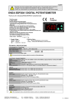
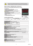
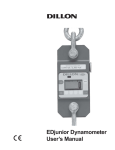
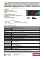
ENDA EDP2041 DIGITAL POTENTIOMETER
Thank you for choosing ENDA EDP2041 potentiometer.
* 35x77mm sized.
* 4 digits display.
* Easy to use by front panel keypad.
* Communication via RS-485 Modbus protocol or
synchronous running between two or more potentiomers.
(Optional)
* Preset value can be adjusted from external buttons.
* Display scale can be adjusted between -1999 and 9999.
(Full scale can not be higher than a 9999)
* Decimal point can be adjusted between 1. and 3. digits.
* 0-10V,0-20 mA a and 4-20mA output with adjustable minimum and
maximum values.
* ‘Soft on’ and ‘soft off’ properties can be selected.
* Parameter access protection on 3 levels.
* CE marked according to European Norms.
TX
RX
AOUT
SET
ENDA
DIGITAL POTENTIOMETER
EDP2041
Order Code : EDP2041- -
1
2
1- Supply Voltage
230VAC...230V AC
24VAC.....24V AC
SM...........9-30V DC / 7-24V AC
2- Modbus Option
RS......With RS-485 Modbus communication
Empty.....Without RS-485 Modbus communication
TECHNICAL SPECIFICATIONS
ENVIRONMENTAL CONDITIONS
Ambient/storage temperature 0 ... +50°C/-25 ... +70°C (without icing)
80% Relative humidity for temperatures up to 31 % °C, decreasing linearly to 50% at 40°C.
Max. relative humidity
According to EN 60529
Front panel : IP65
Rated pollution degree
Rear panel : IP20
Height
Max. 2000m
Do not use the device in locations subject to corrosive and flammable gases.
ELECTRICAL CHARACTERISTICS
Supply
Power consumption
Wiring
Date retention
EMC
Safety requirements
230V AC +10% -20%, 50/60Hz or 24V AC ±10% 50/60Hz or optional 9-30V DC / 7-24V AC ±10% SMPS
Max. 7VA
2.5mm² Screw Connections
EEPROM (Min. 10 years)
EN 61326-1: 2013 (Performance criterion B for the EMC standards)
EN 61010-1: 2012 (pollution degree 2, overvoltage category II, measurement category I)
INPUTS
Upwards input (UP)
Downwards input (DOWN)
Contact input or max. 24VDC logic input (active low)
Contact input or max. 24VDC logic input (active low)
OUTPUT
0-10V output
Digitally adjusted maximum 10mA, max. 10V potentiometer output.
Accuracy :%0.1 Resolution : 1mV
Fluctuation : Maximum 30mV
Rise time from 0 to 10V is maximum 300ms
OUTPUT
0-20mA output
Digitally adjusted maximum 12V, max.20 mA potentiometer output.
Accuracy: %0.1 Resolution : 2µA
Fluctuation : Maximum 60µA
Rise time from 0 to 20mA is maximum 300ms
HOUSING
Housing type
Dimensions
Weight
Enclosure material
Suitable for flush-panel mounting according to DIN 43 700.
W77xH35xD71mm
Approx. 350g (after packing)
Self extinguishing plastics
While cleaning the device, solvents (thinner, benzine, acid etc.) or corrosive materials must not be used.
SİSEL MÜHENDİSLİK ELEKTRONİK SAN. VE TİC. A.Ş.
Şerifali Mah. Barbaros Cad. No:18 Y.Dudullu 34775
ÜMRANİYE/İSTANBUL-TURKEY
Tel : +90 216 499 46 64 Pbx. Fax : +90 216 365 74 01
url : www.enda.com.tr
1/4
EDP2041-T-03-201406
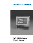
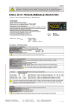
TERMS
1) Adjusted potentiometer value is seen in run mode
Parameter name, value or its unit in programming mode.
TX
RX
AOUT
2) Increment key during run mode.
Increment or parameter selection key during programming mode.
SET
3) Decrement key during run mode.
Decrement or parameter selection key during programming mode.
ENDA
EDP2041
DIGITAL POTENTIOMETER
4) Used for selecting run or programming modes and for adjusting parameters.
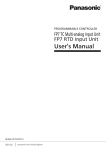
( 1 ) Digital display
12,5 mm 4 digits 7 segment red LED display
( 2 ),( 3 ),( 4 ) Keypad
Micro switch
DIMENSIONS
Depth
77mm
RX
61mm
5mm
Flush mounting
clamp
+
7
8
-
9
+
6
Made in Turkey
1
EDP2041-230VAC-RS
DIGITAL POTENTIOMETER
10
11 12
A
B
-
+
5
8 680407 703142
ENDA INDUSTRIAL ELECTRONICS
SN: XXXXXXXXX
29,5mm
4
Rubber
Flush mounting
packing
clamp
To remove the device from panel:
- While pushing the the flushmounting clamp in direction 1,pull out
it in direction 2.
71,5mm
3
2
2
Connection
cables
Panel cut-out
1
UP
EDP2041
DOWN
V OUT
DIGITAL POTENTIOMETER
mA OUT
ENDA
RS- 485
SET
RS-485 COM.
35mm
AOUT
230V AC +10% -20%
50/60Hz 5VA
TX
Panel
Note :
1) Panel thickness should be maximum 7mm.
2) There must be at least 60mm free space behind the
device, otherwise it would be difficult to remove it from
the panel.
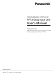
ENDA EDP2041 is intended for installation in control panels. Make sure that the device is used only for intended purpose. The
electrical connections must be carried out by a qualified staff and must be according to the relevant locally applicable regulations.
During an installation, all of the cables that are connected to the device must be free of electrical power. The device must be protected
against inadmissible humidity, vibrations, severe soiling.Make sure that the operation temperature is not exceeded. The cables
should not be close to the power cables or components.
Line
Neutral
184-253V AC 1
50/60Hz 7VA 2
9
1
11 12
10
Fuse
F 100 mA 250V AC
2
3
4
5
6
9
10
A
11 12
1
2
3
4
5
6
7
8
9
-
RS- 485
RS-485 COM.
V OUT
-
mA OUT
UP
DOWN
RS- 485
RS-485 COM.
V OUT
8
Made in Turkey
B
A
11 12
10
Equipment is protected throughout
by DOUBLE INSULATION.
Switch
Holding screw
0.4-0.5Nm
Note :
1) Mains supply cords shall meet the requirements of IEC 60227 or IEC 60245.
2) In accordance with the safety regulations, the power supply switch shall bring the
identification of the relevant instrument and it should be easily accessible by the
operator.
230V AC
Supply
Fuse should
be connected
7
mA OUT
V OUT
SUPPLY :
mA OUT
UP
NOTE :
8
8 680407 703166
+
7
B
9-30V DC / 7-24V AC
±10 % 7VA
SN: XXXXXXXXX
+
6
-
EDP2041-SM-RS
DIGITAL POTENTIOMETER
+
5
ENDA INDUSTRIAL ELECTRONICS
+
4
-
+
3
Made in Turkey
+
2
-
230V AC +10% -20%
50/60Hz 5VA
SN: XXXXXXXXX
8 680407 703142
+
+
1
EDP2041-230VAC-RS
DIGITAL POTENTIOMETER
8 680407 703111
Made in Turkey
DOWN
230V AC +10% -20%
50/60Hz 5VA
ENDA INDUSTRIAL ELECTRONICS
SN: XXXXXXXXX
UP
EDP2041-230VAC
DIGITAL POTENTIOMETER
DOWN
ENDA INDUSTRIAL ELECTRONICS
Cable size: 1,5mm²
120 Ohm
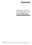
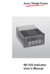
CONNECTION DIAGRAM FOR SYNCHRONOUS RUNNING
120 Ohm
Max. 127 potentiometers
can be controlled.
+
+
11 12
8 680407 703142
EDP2041-230VAC-RS
DIGITAL POTENTIOMETER
ENDA INDUSTRIAL ELECTRONICS
1
2
3
4
5
6
7
8
9
A
B
-
+
10
SN: XXXXXXXXX
+
9
230V AC +10% -20%
50/60Hz 5VA
-
+
8
-
10
11 12
8 680407 703142
EDP2041-230VAC-RS
DIGITAL POTENTIOMETER
ENDA INDUSTRIAL ELECTRONICS
1
2
3
4
5
6
7
8
9
A
B
-
+
7
SN: XXXXXXXXX
+
6
230V AC +10% -20%
50/60Hz 5VA
-
10
11 12
8 680407 703142
EDP2041-230VAC-RS
DIGITAL POTENTIOMETER
ENDA INDUSTRIAL ELECTRONICS
1
2
3
4
5
6
7
8
9
A
B
-
+
5
+
4
+
3
230V AC +10% -20%
50/60Hz 5VA
-
10
11 12
A
B
-
+
2
+
1
230V AC +10% -20%
50/60Hz 5VA
UP
DOWN
V OUT
mA OUT
RS- 485
Slave
potentiometer-2
RS-485 COM.
UP
DOWN
V OUT
mA OUT
RS- 485
8 680407 703142
EDP2041-230VAC-RS
DIGITAL POTENTIOMETER
SN: XXXXXXXXX
Slave
potentiometer-1
RS-485 COM.
UP
DOWN
V OUT
RS- 485
mA OUT
RS-485 COM.
UP
DOWN
V OUT
RS- 485
mA OUT
RS-485 COM.
ENDA INDUSTRIAL ELECTRONICS
SN: XXXXXXXXX
Master
potentiometer
Slave
potentiometer-127
NOTE :
- d.Adr. parameter should be selected C.Pot in master potentiometer. In this case d.Adr. parameter of other potentiometers aren’t used. But be sure that
C.Pot isn’t selected in slave potentiometers to prevent confusion. Settings of slave potentiometers change proportional to setting of master potentiometer. For
example; When Max. output of master potentiometer is changed from 10V to 5V, max. output of slave potentiometers decrease half of previous value
proportional to this. If previous output of slave potentiometer is 6V, it decreases 3V. P.on.c parameter of slave potentiometer should be selected oFF in order
to understand master potentiometer when slave is energized.
- Computer should be used to change only a few potentiometers. In this case, there is not master potentiomer. Output of the required potentiometer is
changed according to d.Adr. parameter.
- Baud rate of potentiometers must be same in both conditions. 120 Ohm termination resistor should be used at the ends and beginning of transmission line.
See www.enda.com.tr/EDP2041.htm for detailed information.
2/4
EDP2041-E-03-201406
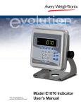
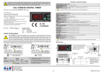
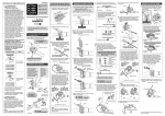
Run mode
Preset
value
Active
output value
SET
PrSt.
1000
or
1001
1000
1002
1002
1003
If no key is pressed
for 3 seconds
If o.Et.y and o.d.t.Y parameters are adjusted to any value expect dSAb parameter,
output can be controlled with and buttons.
SET
key is pressed whole in the run mode,preset setup mode is entered and PrSt. message is displayed. Message appears when the
or button is pressed, the preset value starts to flash.
By using
keys ,preset value can be adjusted.Preset value can be adjusted by using external buttons as well.External buttons become disable in programming mode.If the device is also controlled by a potentiometer,
adjustable preset value appears as above.
SET
SET
+
key is pressed while holding down to
the programming mode is entered
key
Entering from programming mode to run mode:
If no key is pressed within 20 seconds during programming mode data is SET
stored automatically and the run mode is entered.After pressing
to the program menu by pressing
key is pressed in combination with
keys and the information is recorded.
button and
then passed
SET
+
Programming mode
SET
SET
0
L.ScL..
9999
H.ScL.
Lo.Li.
0
Off
pon.C.
L.ScL..= Lower value of the scale.Adjustable between -1999 and
(H.SCL.-10).
Scale the lower value of the output,based on o.typ.. parameter
selection, it is 0V,0mA or 4mA
See NOTE 1 for programming.
H.ScL..= Upper value of the scale.
Adjustable between (L.SCL.+10) and 9999.
Scale the upper value of the output based on, o.typ.. parameter
selection;it is 10V or 20 mA. H.SCL. and L.SCL. difference can
not be greater than 9999.
See NOTE 1 for programming.
Lo.Li..= The lower limit of the preset value.
Adjustable between L.ScL. and (Hi.Li.-10).
DsaB
DsaB
o.E.ty.
o.d.ty..
See NOTE 1 for programming.
1500
Hi.Li.
Hi.Li..= The upper limit of the preset value.
Adjustable between (L.o.li.+10) and H.SCl.
See NOTE 1 for programming.
1
d.ADr.
d.Adr.=Device address for ModBus.
Adjustable between 1-247 or selectable c.Pot. .When c.Pot. is
selected,the device will be master potentiometer and slave
potentiometers can be adjusted dependent on it.
See NOTE 1 for programming
This parameter is active device with RS485 communication option.
9.60
bAud
DsaB
DsaB
30
baud = Baud rate for the RS485 connection.
Adjustable;off,2400,4800,9600,19200 and 38400.
This parameter is active device with RS485 communication
30
option.
1
SET
SET
Lo.Li.
6
r.ti.
of preset value.
keys, adjustment can be made.
If increment key
is pressed and held 0.6 seconds, the value of the selected parameter
changes rapidly. If waited enough, the value increases 100 at each step. After 1 second following
the release of the key, initial condition is returned. The same procedure is valid for the decrement
key.
0-10
o.typ.. o.tyP.. = Output type selection parameter
SEcu.
Return to
the menu
+
0-10 = 0-10V output usable
4-20 = 4-20mA output usable
0-20 = 0-20mA output usable
See NOTE 1 for programming
o.C.sc.
Return to
the menu
+
o.C.sc. = o.Cnf. Menu protection
level parameter.
nonE = No menu is seen
P.yEs = Modification feasible
P. no = Only traceable
Pno = Menu visible.
OUTPUT DIAGRAM
On
S.str.
Lo.li.
r.ti.
Dsab.
Dsab.
Enb.
Enb.
S.on
S.ofF
PRESET
r.ti.
Lo.li.
Can not control with
buttons.
E.E.ty.
E.d.ti.
Dsab.
Dsab.
When
key When
key
is pressed
is pressed
Enb.
Enb.
When
key
is pressed
d.ti.
When
key
is pressed
S.on
S.ofF
PRESET
Lo.li.
UP input H
L
DOWN input H
L
3/4
p.YES
PRESET
o.E.ty.
o.d.ti.
can not be changed.
Selected according to the value increase or
decrease the preset buttons for fast switching
mode,the preset value speedy is increased or
decreased “one by one”,10 at each step,100
at each step,1000 at each step.
key. Then, by using
U.c.Sc. = U.cnF. menu protection
level parameter.
On
It is adjustedİ dSAb. ,1, 10,100 ve 1000
values. dSAb is selected,the preset value
6
U.C.sc.
S.Cod = Access code for safety
menu.
This parameter should be 2041.
Security code is 0; key is pressed
continuously for 5 secoonds,dEfP
message is displayed and return to
0V
Adjustable between 1-250 seconds.
Output is decreased slowly the lower limit
value during adjusted time.
See NOTE 1 for programming.
P.i.rt. Pi.rt.. = Increasing and decreasing speed
off
Power
d.ti. d.ti. = Decreasing time for output value.
SET
For adjusting a selected parameter first press and hold
r.ti. = Increasing time for output.
Adjustable between 1-250 seconds.Output is
increased slowly to the lower limit value
during adjusted time.
P.on.C.
p.YES
U.CnF..
button
E.d.ty..
SET
5
o.d.ty. = Adjusted type of the output to lower limit value with
button.
dSAb.= Output can not be adjusted to lower limit value with
button.
Enb. = Output can be adjusted to lower limit value with button.
S.oFF = Output is increased to voltage that lower limit value is displayed with
during dtI.
See NOTE 1 for programming.
E.d.ty. = Returning method of the output to
preset value with the external "Down" input.
o.d.tY. is set like the output parameter.
Parameter adjustment method
NOTE 1
button during r.tI
E.E.ty. = Returning method of the output to preset value with the external "Up" input.
o.E.tY. is set like the output parameter.
While the parameter names appear,
and
keys are
pressed together,the program will return to the menu display.
+
o.E.ty. = Adjusted type of the output to preset value with
button.
dSAb.= Output can not be adjusted to preset value with
button.
Enb. = Output can be adjusted to preset value with
button.
S.on = Output is increased to voltage that set value is displayed with
See NOTE 1 for programming.
S.Cod.
nonE = No menu is seen
P.yEs = Modification feasible
P. no = Only traceable
E.E.ty..
o.cnF.
Return to
the menu.
P.on.C. = Selection of the output parameter behavior
ofF= When first energized, output is the voltage or current that lower limit value is indicated.
Attention: If this parameter is selected, the set value that was adjusted before is seen when set button is
pressed at first. In addition,if increasing or decreasing that value is wanted the set value is equalized to
lower limit value and then adjustment can be done.
On= When first energized, output is the voltage or current hat the set value is indicated.
S.Str.= When first energized, output is increased slowly from the voltage or current that lower limit value is
indicated to the voltage or current that set value is indicated during r.ti.
See NOTE 1 for programming.
Out
d.Pnt.
Default
parameters
Default
parameters
Out
0
d.PNt..= Display decimal point parameter
Decimal point can be adjusted between 1. and 3. digits.
See NOTE 1 for programming.
Out
Default
Parameters
SET
SECu.
o.CnF.
U.CnF..
preset increased
r.ti.
d.ti.
preset decremented
EDP2041-E-03-201406
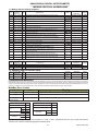
ENDA EDP2041 DIGITAL POTENTIOMETER
MODBUS PROTOCOL ADDRESS MAP
1.1 Memory map for Holding Registers
Parameter Holding Register
addresses
Number
Decimal (Hex)
Data
Type
Parameter
Name
Data Content
H0 0000d (0000h) Word Percentage of the external control.Adjustable between %0.00 and %100.0
H1
0001d
(0001h) Word
Preset value
H2 0002d (0002h) Word Decimal point
H3 0003d (0003h) Word The lower value of the scale
H4 0004d (0004h) Word The upper value of the scale
H5 0005d (0005h) Word
The lower limit of the preset value
H6 0006d (0006h) Word
The upper limit of the preset value
H7 0007d (0007h) Word
Device address for Rs485 network connection (Adjustable between 1-247.)
If set to “0”,the control potentiometer mode is entered.
Baud rate selection ( 0= None;1=2400bps ; 2=4800bps ; 3=9600bps ;
4=19200bps; 5=38400bps)
The first opening the control parameter
0= off, 1= on , 2 = S.Str
Output upper arrow button to fetch the value of the preset selection
0= dsab.,1= Enb. , 2 = S.on.
Output lower arrow button to fetch the value of the lower limit selection
0= dsab.,1= Enb., 2 = S.off.
Time to increase the output voltage
H8 0008d (0008h) Word
H9 0009d (0009h) Word
H10 0010d (000Ah) Word
H11 0011d (000Bh) Word
H12 0012d (000Ch) Word
H13 0013d (000Dh) Word Time to decrease the output voltage
Preset the value of the increament and decrement rate or cancel the setting
H14 0014d (000Eh) Word 0 = cancel, 1=1,2=10,3=100,4=1000.
H15 0015d (000Fh) Word
H16 0016d (0010h) Word
H17 0017d (0011h) Word
H18
0018d
(0012h) Word
H19 0019d (0010h) Word
H20 0020d (0011h) Word
Output type selection parameter
0 = 0-10V output, 1 = 4-20mA output ,2 = 0-20mA output
User security parameter configuration menu (0 = Menu invisible,
1= Menu programmable, 2 or 3 = Menu only traceable).
Output security parameter configuration menu (0 = Menu invisible,
1= Menu programmable, 2 or 3 = Menu only traceable).
Function control parameter
(23040d (5A00h) value is entered,any function executed.
(23041d (5A01h) value is entered,the default values will be restored.
Returning method of the output to preset value with the external "Up" input.
0 = dSAb. , 1 = Enb. , 2 = S.on.
Returning method of the output to preset value with the external "Down" input.
0 = dsab . 1= Enb., 2 = S.off.
PrSt.
D.PNT.
L.SCL.
H.SCL.
Lo.Li.
Hi.Li.
D.adr.
Baud.
P.oN.C.
o.E.ty.
o.d.ty.
r.ti.
D.ti.
P.idt.
o.tyP.
U.C.SC.
o.C.SC.
Read/Write
Permission
Default
Parameters
Readable / Writable
10000
Readable / Writable
1000
Readable / Writable
0
Readable / Writable
0
Readable / Writable
9999
Readable / Writable
0
Readable / Writable
2000
Readable / Writable
1
Readable / Writable
3
Readable / Writable
0
Readable / Writable
0
Readable / Writable
0
Readable / Writable
30
Readable / Writable
30
Readable / Writable
1
Readable / Writable
0
Readable / Writable
1
Readable / Writable
1
0
Readable / Writable
E.E.t.y.
E.d.t.y.
Readable / Writable
0
Readable / Writable
0
Parameter
Name
Read/Write
Permission
1.2 Memory map for Coils
I0
Input Register
Data
addresses
Type
Decimal (Hex)
0000d (0000h) Word
I1
(0001h) Word
Parameter
Number
0001d
Data Content
Instant set value
% of value the analog output (%0.00-%100.00 sensitivity)
---
Only readable
Only readable
Default
Parameters
---
1.3 Memory map for Discrete Input
Parameter Discrete input Data
Number
addresses
Type
Parameter
Name
Data Content
D0
(0000)h
Bit
State of the external down button (0 = OFF ,1 = ON)
D1
(0001)h
Bit
State of the external up button (0 = OFF ,1 = ON)
---
Read/Write
Permission
Only readable
Only readable
Default
Parameters
---
2. MODBUS ERROR MESSAGES
Modbus protocol has two types error, communication error and operating error. Reason of the communication error is data corruption in transmission. Parity and CRC
control should be done to prevent communication error. Receiver side checks parity and CRC of the data. If they are wrong, the message will be ignored. If format of
the data is true but function doesn’t perform for any reason, operating error occurs. Slave realizes error and sends error message. Most significant bit of function is
changed '1' to indicate error in error message by slave. Error code is sent in data section. Master realizes error type via this message.
ModBus Error Codes
Meaning
Name
Error Code
The function code received in the query is not an allowable action for the slave. If a Poll Program
Complete command was issued, this code indicates that no program function preceded it.
{01}
ILLEGAL FUNCTION
{02}
ILLEGAL DATA ADDRESS
{03}
ILLEGAL DATA VALUE
The data address received in the query is not an allowable address for the slave.
A value contained in the query data field is not an allowable value for the slave.
Message example;
Structure of command message (Byte Format)
Structure of response message (Byte Format)
Device Address
(0A)h
Device Address
(0A)h
Function Code
(01)h
Function Code
(81)h
Error Code
(02)h
Beginning address
of coils.
Number of coils (N)
MSB
(04)h
LSB
(A1)h
MSB
(00)h
LSB
(01)h
LSB
(AC)h
MSB
(63)h
LSB
(B0)h
MSB
(53)h
CRC DATA
CRC DATA
As you see in command message, coil information of (4A1)h = 1185 is required but there isn’t any coil with 1185 address.
Therefore error code with number (02) (Illegal Data Address) sends.
4/4
EDP2041-E-03-201406