1
Flexible Duty Roster
for Doctors in Hospitals
TDT4290 Customer Driven Project
Arve Nymo Skogvold
Thorbjørn Sæther
Susanne Sousa Moseby
Petter Westby
Even Bruvik Frøyen
Fall 2009
Preface
This report is the result of a group assignment in the course TDT4290 Customer
Driven Project at the Norwegian University of Science and Technology. It was
carried out by group 3 during the autumn of 2009. The group consisted of five
students from the Department of Computer and Information Science.
Our assignment, given by the Ear, Nose and Throat (ENT) Department at St.
Olavs Hospital, was to make a program that could assist the department in creating a
work schedule for the doctors. This scheduling was done manually, and was very time
consuming. Our program should be able to do the regular scheduling automatically,
given a number of constraints given by the customer. Irregularities, like when an
employee is absent, will be resolved manually. By inserting these resolutions back
into the system, it should be able to continue with the regular scheduling.
We would like to offer our gratitude to our supervisors Basit A. Khan and Andreas Landmark for their invaluable feedback and support from day one and throughout the project.
We would also like to thank the customer representatives Ellen Jaatun and Leif
Anders Holmen for their trust and prompt communication during the project.
Even Bruvik Frøyen
Susanne Sousa Moseby
Petter Westby
Thorbjørn Sæther
Arve Nymo Skogvold
i
ii
Abstract
The current method for planning shifts at the St. Olavs Hospital university hospital
in Trondheim is a manual process, requiring several hours per week due to small
alterations and unnoticed conflicts. There are several constraints involved with
different tasks and work hours. Shifts have to be fairly distributed to the junior
doctors, junior doctors being attached to a supervisor for shifts, and constraints
apply on the length of period a doctor is allowed to work uninterrupted.
The employees associated with this work in the Ear, Nose and Throat department
of the hospital expressed an interest in a partially automated solution to this task,
in an effort to reduce the amount of work and time spent. They indicated that other
departments had similar issues, and might as such also be interested in any product
solving this problem.
A web application was designed and implemented by this group in accordance
with the requirements set forth by the customer. An effort was also made to make
the design as flexible as possible, enabling other departments to utilize the finished
product as well. Design and implementation was performed over four iterations,
using an agile software development method.
Due to time and resource constraints, certain low priority, nice-to-have requirements were not implemented, but the system was designed to be easy to extend and
modify. The system was not believed to be fully portable between domains in its
current incarnation, but was considered by the group to be a solid proof of concept.
Testing has indicated that the resultant product could prove usable for the Ear,
Nose and Throat department of the hospital. The project group would expect a
significant decrease in the time spent on scheduling shifts at this department.
iii
iv
Contents
1 Introduction
1.1 Project Description . . . . . . . . . . . . . . . . . . . . . . . . . . . .
1
1
2 Project Management
5
2.1 Project Organization . . . . . . . . . . . . . . . . . . . . . . . . . . . 5
2.2 Sprints . . . . . . . . . . . . . . . . . . . . . . . . . . . . . . . . . . . 10
2.3 Procedures for Quality Assurance . . . . . . . . . . . . . . . . . . . . 11
3 Preliminary Studies
3.1 The Situation Today . . . . . . . . . . . . . . . . . . . . . . . . . . .
3.2 Frameworks Used in the Project . . . . . . . . . . . . . . . . . . . . .
3.3 Tools Used in the Project . . . . . . . . . . . . . . . . . . . . . . . .
13
13
15
18
4 Requirement Specification
23
4.1 Foundation . . . . . . . . . . . . . . . . . . . . . . . . . . . . . . . . 23
4.2 Overall Description . . . . . . . . . . . . . . . . . . . . . . . . . . . . 24
4.3 Specific Requirements . . . . . . . . . . . . . . . . . . . . . . . . . . . 26
5 Sprint 1
5.1 Planning . . . .
5.2 Design . . . . .
5.3 Name and Logo
5.4 Implementation
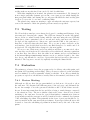
5.5 Testing . . . . .
5.6 Evaluation . . .
6 Sprint 2
6.1 Planning . . . .
6.2 Implementation
6.3 Testing . . . . .
6.4 Evaluation . . .
.
.
.
.
.
.
.
.
.
.
.
.
.
.
.
.
.
.
.
.
.
.
.
.
.
.
.
.
.
.
.
.
.
.
.
.
.
.
.
.
.
.
.
.
.
.
.
.
.
.
.
.
.
.
.
.
.
.
.
.
.
.
.
.
.
.
.
.
.
.
7 Sprint 3
7.1 Planning . . . . . . . . . . .
7.2 Design and Implementation
7.3 Testing . . . . . . . . . . . .
7.4 Evaluation . . . . . . . . . .
.
.
.
.
.
.
.
.
.
.
.
.
.
.
.
.
.
.
.
.
.
.
.
.
.
.
.
.
.
.
.
.
.
.
.
.
.
.
.
.
.
.
v
.
.
.
.
.
.
.
.
.
.
.
.
.
.
.
.
.
.
.
.
.
.
.
.
.
.
.
.
.
.
.
.
.
.
.
.
.
.
.
.
.
.
.
.
.
.
.
.
.
.
.
.
.
.
.
.
.
.
.
.
.
.
.
.
.
.
.
.
.
.
.
.
.
.
.
.
.
.
.
.
.
.
.
.
.
.
.
.
.
.
.
.
.
.
.
.
.
.
.
.
.
.
.
.
.
.
.
.
.
.
.
.
.
.
.
.
.
.
.
.
.
.
.
.
.
.
.
.
.
.
.
.
.
.
.
.
.
.
.
.
.
.
.
.
.
.
.
.
.
.
.
.
.
.
.
.
.
.
.
.
.
.
.
.
.
.
.
.
.
.
.
.
.
.
.
.
.
.
.
.
.
.
.
.
.
.
.
.
.
.
.
.
.
.
.
.
.
.
.
.
.
.
.
.
.
.
.
.
.
.
.
.
.
.
.
.
.
.
.
.
.
.
.
.
.
.
.
.
.
.
.
.
.
.
.
.
.
.
.
.
.
.
.
.
.
.
.
.
.
.
.
.
.
.
.
.
.
.
.
.
.
.
.
.
.
.
.
.
.
.
.
.
37
37
38
39
40
41
43
.
.
.
.
45
45
46
51
54
.
.
.
.
57
57
58
60
60
8 Sprint 4
8.1 Planning . . . .
8.2 Logo . . . . . .
8.3 Implementation
8.4 Final View . . .
8.5 Testing . . . . .
8.6 Evaluation . . .
.
.
.
.
.
.
.
.
.
.
.
.
.
.
.
.
.
.
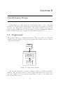
9 Overall System Design
9.1 Deployment . . . . .
9.2 The web application
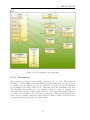
9.3 The Packages . . . .
9.4 JSP . . . . . . . . .
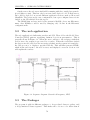
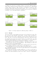
9.5 Sequence diagrams .
.
.
.
.
.
.
.
.
.
.
.
10 Evaluation
10.1 Process . . . . . . . . .
10.2 Tools and Frameworks
10.3 The Product . . . . . .
10.4 Conclusion . . . . . . .
.
.
.
.
.
.
.
.
.
.
.
.
.
.
.
.
.
.
.
.
.
.
.
.
.
.
.
.
.
.
.
.
.
.
.
.
.
.
.
.
.
.
.
.
.
.
.
.
.
.
.
.
.
.
.
.
.
.
.
.
.
.
.
.
.
.
.
.
.
.
.
.
.
.
.
.
.
.
.
.
.
.
.
.
.
.
.
.
.
.
References
.
.
.
.
.
.
.
.
.
.
.
.
.
.
.
.
.
.
.
.
.
.
.
.
.
.
.
.
.
.
.
.
.
.
.
.
.
.
.
.
.
.
.
.
.
.
.
.
.
.
.
.
.
.
.
.
.
.
.
.
.
.
.
.
.
.
.
.
.
.
.
.
.
.
.
.
.
.
.
.
.
.
.
.
.
.
.
.
.
.
.
.
.
.
.
.
.
.
.
.
.
.
.
.
.
.
.
.
.
.
.
.
.
.
.
.
.
.
.
.
.
.
.
.
.
.
.
.
.
.
.
.
.
.
.
.
.
.
.
.
.
.
.
.
.
.
.
.
.
.
.
.
.
.
.
.
.
.
.
.
.
.
.
.
.
.
.
.
.
.
.
.
.
.
.
.
.
.
.
.
.
.
.
.
.
.
.
.
.
.
.
.
.
.
.
.
.
.
.
.
.
.
.
.
.
.
.
.
.
.
.
.
.
.
.
.
.
.
.
.
.
.
.
.
.
.
.
.
.
.
.
.
.
.
.
.
.
.
.
.
.
.
.
.
.
.
.
.
.
.
.
.
.
.
.
.
.
.
.
.
.
.
.
.
.
.
.
.
.
.
.
.
.
.
.
.
.
.
.
.
.
.
.
.
.
.
.
.
.
.
.
63
63
64
64
66
68
69
.
.
.
.
.
73
73
74
74
83
83
.
.
.
.
87
87
90
93
97
99
Appendices
101
A Risk Analysis
A-1
B Version control – procedures
B-1
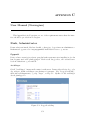
C User Manual (Norwegian)
C-1
D Installation guide (Norwegian)
D-1
E Testing
E-1
vi
List of Figures
2.1
2.2
Gantt chart . . . . . . . . . . . . . . . . . . . . . . . . . . . . . . . .
Work Breakdown Structure . . . . . . . . . . . . . . . . . . . . . . .
3.1
3.2
3.3
The Scrum Process (adopted from Softhouse.se) . . . . . . . . . . . . 16
Screenshot of Trac . . . . . . . . . . . . . . . . . . . . . . . . . . . . 19
Screenshot from VersionOne: A part of the storyboard . . . . . . . . 20
4.1
4.2
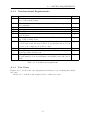
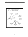
4.3
Defining the domain . . . . . . . . . . . . . . . . . . . . . . . . . . . 28
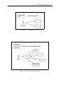
Logging in and out . . . . . . . . . . . . . . . . . . . . . . . . . . . . 29
Viewing a scheduled plan . . . . . . . . . . . . . . . . . . . . . . . . . 29
5.1
5.2
5.3
5.4
Screenshot of Balsamiq Mockups .
Class diagram: Package overview .
Class diagram: A closer look on the
Burn down chart . . . . . . . . . .
6.1
6.2
6.3
6.4
6.5
6.6
6.7
6.8
Screenshot: Showing Employees . . . .
Package overview . . . . . . . . . . . .
Class diagram: Package: servlets . . .
Class diagram: Package: authentication
Class diagram: Package: model . . . .
Class diagram: Package: persistence . .
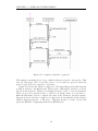
Sequence diagram: Log in . . . . . . .
Burn down chart . . . . . . . . . . . .
7.1
7.2
Screenshot of calendar . . . . . . . . . . . . . . . . . . . . . . . . . . 59
Burn down chart . . . . . . . . . . . . . . . . . . . . . . . . . . . . . 61
8.1
8.2
8.3
8.4
Class diagram: model
Old plan . . . . . . .
New plan . . . . . .
Burn down chart . .
.
.
.
.
.
.
.
.
.
.
.
.
.
.
.
.
.
.
.
.
.
.
.
.
.
.
.
.
.
.
.
.
.
.
.
.
.
.
.
.
.
.
.
.
65
67
68
70
9.1
9.2
9.3
9.4
9.5
9.6
9.7
9.8
9.9
Deployment diagram . . . . . . . . . . . . . . . . .
Sequence diagram: General call sequence, MVC . .
Package diagram: the different packages of Khronos
Class diagram: model package . . . . . . . . . . . .
Class diagram: persistence package . . . . . . . . .
Class diagram: scheduler package . . . . . . . . . .
Class diagram: servlets package . . . . . . . . . . .
Class diagram: listeners package . . . . . . . . . . .
Class diagram: authentication package . . . . . . .
.
.
.
.
.
.
.
.
.
.
.
.
.
.
.
.
.
.
.
.
.
.
.
.
.
.
.
.
.
.
.
.
.
.
.
.
.
.
.
.
.
.
.
.
.
.
.
.
.
.
.
.
.
.
.
.
.
.
.
.
.
.
.
.
.
.
.
.
.
.
.
.
.
.
.
.
.
.
.
.
.
.
.
.
.
.
.
.
.
.
73
74
75
77
78
79
80
81
82
package
. . . . .
. . . . .
. . . . .
.
.
.
.
.
.
.
.
vii
.
.
.
.
. . . . . . . . .
. . . . . . . . .
model package.
. . . . . . . . .
.
.
.
.
.
.
.
.
.
.
.
.
.
.
.
.
.
.
.
.
.
.
.
.
.
.
.
.
.
.
.
.
.
.
.
.
.
.
.
.
.
.
.
.
.
.
.
.
.
.
.
.
.
.
.
.
.
.
.
.
.
.
.
.
.
.
.
.
.
.
.
.
.
.
.
.
.
.
.
.
.
.
.
.
.
.
.
.
7
8
.
.
.
.
.
.
.
.
.
.
.
.
.
.
.
.
.
.
.
.
.
.
.
.
.
.
.
.
.
.
.
.
.
.
.
.
.
.
.
.
39
41
42
44
.
.
.
.
.
.
.
.
.
.
.
.
.
.
.
.
.
.
.
.
.
.
.
.
.
.
.
.
.
.
.
.
.
.
.
.
.
.
.
.
.
.
.
.
.
.
.
.
.
.
.
.
.
.
.
.
.
.
.
.
.
.
.
.
.
.
.
.
.
.
.
.
.
.
.
.
.
.
.
.
47
47
48
50
52
53
53
55
9.10 Class diagram: utilities package . . . . . . . . . . . . . . . . . . . . . 83
9.11 Sequence diagram: logging in . . . . . . . . . . . . . . . . . . . . . . 84
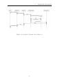
9.12 Sequence diagram: show employees . . . . . . . . . . . . . . . . . . . 85
C.1 Legg til avdeling . . . .
C.2 Legg til stilling . . . . .
C.3 Legg til oppgavekategori
C.4 Å definere en oppgave .
C.5 Å redigere en ukeplan . .
C.6 Å definere en ansatt . .
C.7 Velg periode . . . . . . .
C.8 Planlegging . . . . . . .
C.9 Konflikt . . . . . . . . .
C.10 Vis plan . . . . . . . . .
C.11 Vis plan . . . . . . . . .
.
.
.
.
.
.
.
.
.
.
.
.
.
.
.
.
.
.
.
.
.
.
.
.
.
.
.
.
.
.
.
.
.
.
.
.
.
.
.
.
.
.
.
.
.
.
.
.
.
.
.
.
.
.
.
viii
.
.
.
.
.
.
.
.
.
.
.
.
.
.
.
.
.
.
.
.
.
.
.
.
.
.
.
.
.
.
.
.
.
.
.
.
.
.
.
.
.
.
.
.
.
.
.
.
.
.
.
.
.
.
.
.
.
.
.
.
.
.
.
.
.
.
.
.
.
.
.
.
.
.
.
.
.
.
.
.
.
.
.
.
.
.
.
.
.
.
.
.
.
.
.
.
.
.
.
.
.
.
.
.
.
.
.
.
.
.
.
.
.
.
.
.
.
.
.
.
.
.
.
.
.
.
.
.
.
.
.
.
.
.
.
.
.
.
.
.
.
.
.
.
.
.
.
.
.
.
.
.
.
.
.
.
.
.
.
.
.
.
.
.
.
.
.
.
.
.
.
.
.
.
.
.
.
.
.
.
.
.
.
.
.
.
.
.
.
.
.
.
.
.
.
.
.
.
.
.
.
.
.
.
.
.
.
.
.
.
.
.
.
.
.
.
.
.
.
.
C-1
C-2
C-2
C-4
C-5
C-5
C-6
C-7
C-7
C-8
C-9
List of Tables
2.1
2.2
2.3
Roles . . . . . . . . . . . . . . . . . . . . . . . . . . . . . . . . . . . . 5
Risk summary . . . . . . . . . . . . . . . . . . . . . . . . . . . . . . . 9
Some important coding guidelines . . . . . . . . . . . . . . . . . . . . 12
4.1
4.2
4.3
4.4
4.5
4.6
4.7
4.8
4.9
4.10
Functional requirements . . . . . . . . . . .
Non-functional requirements . . . . . . . . .
Textual use case: Logging in . . . . . . . . .
Textual use case: Logging out . . . . . . . .
Textual use case: Define a department . . .
Textual use case: Define a task . . . . . . .
Textual use case: Define an employee . . . .
Textual use case: Define a plan . . . . . . .
Textual use case: Make changes to the plan
Textual use case: View plan . . . . . . . . .
5.1
Sprint 1 Backlog . . . . . . . . . . . . . . . . . . . . . . . . . . . . . 38
6.1
Sprint 2 Backlog . . . . . . . . . . . . . . . . . . . . . . . . . . . . . 46
7.1
Sprint 3 Backlog . . . . . . . . . . . . . . . . . . . . . . . . . . . . . 58
8.1
8.2
Sprint 4 Backlog . . . . . . . . . . . . . . . . . . . . . . . . . . . . . 64
System test results . . . . . . . . . . . . . . . . . . . . . . . . . . . . 69
.
.
.
.
.
.
.
.
.
.
.
.
.
.
.
.
.
.
.
.
.
.
.
.
.
.
.
.
.
.
.
.
.
.
.
.
.
.
.
.
.
.
.
.
.
.
.
.
.
.
.
.
.
.
.
.
.
.
.
.
.
.
.
.
.
.
.
.
.
.
.
.
.
.
.
.
.
.
.
.
.
.
.
.
.
.
.
.
.
.
.
.
.
.
.
.
.
.
.
.
.
.
.
.
.
.
.
.
.
.
.
.
.
.
.
.
.
.
.
.
.
.
.
.
.
.
.
.
.
.
.
.
.
.
.
.
.
.
.
.
26
27
30
30
31
32
33
34
35
35
10.1 Milestones . . . . . . . . . . . . . . . . . . . . . . . . . . . . . . . . . 89
10.2 Result: Functional requirements . . . . . . . . . . . . . . . . . . . . . 94
10.3 Result: Non-functional requirements . . . . . . . . . . . . . . . . . . 95
ix
x
CHAPTER
1
Introduction
Scheduling shifts is a tiresome and time consuming task in any business, and
particularly in hospitals where errors are costly, rules are plentiful and changes
are rapid. The person performing this function will have to keep track of all the
employees, distributing hours fairly and avoiding collisions. Rules regulating working
hours and breaks have to be followed and the qualifications of individual employees
need to be paid attention to. Errors result in jobs not being done and in operations
and procedures being delayed or rescheduled, affecting not just the employees of
the hospital but also the patients. Hours are spent every day on this task in every
department, and it is a job nobody wants to do.
In many ways, this task lends itself to automation. While the many rules and
constraints will make the tasks daunting and frustrating to a human being, it also
results in a well defined rule set for a scheduling algorithm. Though it is difficult
to create an algorithm to generally schedule something optimally, a number of constraints and rules will make the job easier and reduce the run time of the necessary
computations.
We have been given the task of trying to implement this automation. This project
goal is to create a tool to automate large parts of this onerous process as requested
by the St. Olavs hospital Ear, Nose and Throat department. Many schedulers have
been created in the past, with varying levels of success, and were generally domain
specific, as will this scheduler be. It will be designed to be used specifically for
scheduling the work of doctors and assistant doctors within a single department
of a hospital, although we expect it to be transferable to all departments in any
Norwegian hospital with some adjustments.
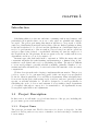
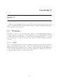
1.1
Project Description
In this section, we will make a top level introduction of the project, including the
project name, sponsor and stakeholders.
1.1.1
Project Name
The given project name was Flexible duty roster for doctors in hospitals. As this
name is both long and not very easy to remember, we had a meeting to brainstorm
for new names.
1
CHAPTER 1. INTRODUCTION
Khronos refers to the Greek god who is the personification of time. He arose
from the original chaos, and is often depicted as an old, gray-haired man with a long
beard. His name literally means time in Greek. We chose this name as it is easy to
remember and relevant to the project goal.
1.1.2
Project Sponsor
The project sponsor is the Ear, Nose and Throat (ENT) (Øre-Nese-Hals) department
at St. Olavs Hospital, a university hospital serving the health care needs of central
Norway. St. Olavs Hospital is the public hospital of the whole of Sør-Trøndelag, it
was first built in 1902 and is today one of the most modern hospitals in Northern
Europe. The hospital has only had its ”St. Olav” name since 2001, when it was
changed from ”Regionsykehuset i Trondheim”. The new name marked the new plans
of building a new and modern university hospital.
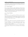
1.1.3
Project Mandate
Purpose
Our assignment is to develop a program for scheduling the work hours of doctors
and doctors in training at the ENT department at St. Olavs Hospital, Trondheim.
Currently, the department uses a manual scheduling system where a secretary uses
around 30 minutes every single day to resolve conflicts and find replacements. This
is both time consuming and error prone, as it can be difficult to see if one person
has been set to be in two places at one time.
Objective
The main objective of this project is to make a program which can assist the staff
in the task of planning the work schedule. The program should only take care of
the long term planning, i.e. one to three months in advance. Changes because
of sickness or other sudden reasons, should be dealt with by the staff — because
otherwise, there would be a much greater need for domain knowledge, more than
the resources of this project will allow.
We intend to deliver the program to the customer, prior to the final presentation.
This way, it can be tested by the customer, so that they could give feedback before the presentation. Read Section 3.2.1 for more information on the development
model.
2
1.1. PROJECT DESCRIPTION
1.1.4
Stakeholders
These are the stakeholders of the project:
Project Group
• Even Bruvik Frøyen - evenbf α gmail.com
• Susanne Sousa Moseby - susannemoseby α gmail.com
• Arve Nymo Skogvold - arve.kpro α skogvold.org
• Thorbjørn Sæther - thorbjsa α gmail.com
• Petter Westby - kpro α pwestby.com
Customer
• Ellen Jaatun - ellen.jaatun α stolav.no
• Leif Anders Holmen - leif.holmen α stolav.no
Supervisors
• Basit Ahmed Kahn - basit α idi.ntnu.no
• Andreas Landmark - andreala α idi.ntnu.no
Others
• The end users
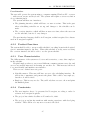
1.1.5
Problem Description
There are two main categories of personnel who are to be included in the plans
generated: senior doctors and junior doctors. The main difference between them is
that the senior doctors have a fixed working schedule. They have the same working
hours from day to day, and do not work night shifts. They do, however, have to
be on-call — one senior doctor every day. This means they are home at night, but
must sometimes respond to emergencies, and show up on short notice.
Junior doctors do work night shifts — one junior doctor at a time. These shifts
are split up in the different week-days, but week-end duty goes from Friday to
Sunday. When working the night shift, a doctor works from 18:00 to 08:00 the
next day. For obvious reasons, this means they will not work the following day.
As the regular working hours are from 07:50 to 16:00, there is a need for a short
shift between 16:00 and 18:00. This is also considered an extra shift, and should be
distributed fairly.
During normal working hours, a junior doctor should usually be assigned to a
supervising senior doctor and follow his schedule.
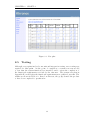
Every week, one junior doctor and one senior doctor have a special kind of shift.
Their tasks then are to follow up on admitted patients and other administrative
work. During this shift, they should not be assigned to any other tasks.
3
CHAPTER 1. INTRODUCTION
4
CHAPTER
2
Project Management
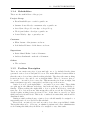
In this chapter we describe how we choose to organize the project. We distribute
roles among the group members, and we set up a time schedule for the different
milestones. A work breakdown structure and risk analysis are also provided, along
with procedures for quality assurance.
2.1
Project Organization
This section introduces the basic project structure, including the project members
and their roles. It also contains the project time plan, along with the work breakdown structure and risk analysis used as the basis for the plan.
We will use the Scrum framework as development model for the project, as
described in Section 3.2.1. This introduces a flat structure, as all project members
join the scrum team, and take tasks off the backlog.
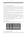
2.1.1
Roles
Although we have a flat structure, the members will also have different roles outside
the Scrum organization. Table 2.1 shows who has which roles.
Arve Skogvold
Even Bruvik Frøyen
Susanne Sousa Moseby
Thorbjørn Sæther
Petter Westby
Project manager, Customer contact
Research manager
Secretary, Supervisor contact
QA manager, Scrum master
Document owner, Test manager
Table 2.1: Roles
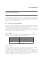
Project Manager
The project manager is responsible for the progress of the group. He is responsible
for calling the group together, and setting up the working organization.
As the project enters the Scrum phases, the sprints, the project organization will
be flatter and the role of the project manager will be more like a regular project
member. We have, however, also assigned him the role as the Scrum ”product
owner”. He will represent and make decisions on behalf of the customer, to make
sure the most important parts of the project are given priority.
5
CHAPTER 2. PROJECT MANAGEMENT
Customer Contact
Point of contact for the customer. The customer will send all mail to this person
(or the mailing list). The customer contact is then responsible for distributing
information to the rest of the group. He coordinates meetings with the customer,
making sure the group and customer all know where and when to meet.
Normally, the customer contact is the only person sending mail to, or in any
other way contacting the customer. This is to make sure that the customer does
not get conflicting messages, or is inconvenienced by having to answer the same
questions several times.
Scrum Master
The Scrum master is responsible for overseeing the Scrum usage of the team and
enforcing the rules of the process. He is a facilitator, and should keep distracting
influences away from the team so they can focus on the task at hand.
Research Manager
In charge of doing research on existing staff scheduling software, and applicable programming frameworks. He shows the group his results, gives information about relevant existing software, and recommends frameworks to be used during the project.
Secretary
Writes minutes from customer- and supervisor meetings. Keeps track of hour registration.
Supervisor Contact
In charge of communications with supervisor. Sends agenda / minutes for supervisor
meetings.
Quality Assurance Manager
In charge of quality assurance, and making sure that the group follows the routines
agreed upon. Following up on document templates and response times are examples
of his work.
Document Owner
Responsible for the progress of the project report. Making document procedures.
Keeps track of what documentation is missing, so that the whole group has a better
picture of what they have to do. He is not supposed to write most of the report on
his own, but must have good overview of what needs to be done.
Test Manager
In charge of the tests that will be used to ensure that the program works according
to our claims. Alerts others about regressions detected during testing.
6
2.1. PROJECT ORGANIZATION
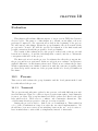
2.1.2
Time Plan
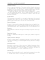
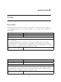
We have set some milestones to follow. One of the rules in Scrum is to never extend
a sprint, but rather postpone tasks. This means that even if the milestones are
reached on the given dates, we could still have tasks left when moving to the next
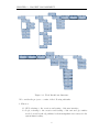
sprint.These milestones are reflected in the Gantt chart, as shown in Figure 2.1.
Figure 2.1: Gantt chart
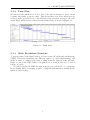
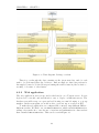
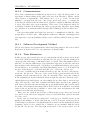
2.1.3
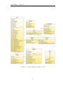
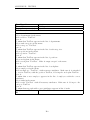
Work Breakdown Structure
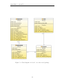
To prepare tasks for the initial backlog, we have set up a Work Breakdown Structure
(WBS). This helps identifying the different tasks to do when implementing, and
makes it easier to estimate how many working hours the different tasks will take.
Figure 2.2 shows the WBS. It has been split in two to make it narrower, so that it
can fit on a page.
We will not update the WBS throughout the project, as it is not a tool in Scrum.
It was mainly made for making us aware of different subtasks when setting up the
initial product backlog.
7
CHAPTER 2. PROJECT MANAGEMENT
1
T
1.1
GUI
1.2
Logikk
1.1.1
Design
1.3
Persistens
1.2.1
Objektmodell
1.4.2
1.4.1
1.4
Dokumentasjon
Klassehierarki
Arkitektur
1.6.3
1.6.2
1.6.1
1.6
Dokumentasjon
Prosedyrer
Testing
1.3.1
Database
1.1.1.1
Research
1.2.1.1
Skall
1.3.2
Hibernate
1.1.1.2
Prototyping
1.2.1.2
Metoder
1.3.3
Testing
1.1.2
Implementasjon
1.5.3.6
1.5.3.5
1.5.3.4
1.5.3.3
1.5.3.2
1.5.3.1
1.5.3
1.5.2
1.5.1
1.5
Kapitteloversikt
Sprint
Rapport
Kap
Navn
Logo
...1 *
4
3
2
1
1.2.1.3
Unit testing
1.1.3
Testing
1.2.2
Sceduling
1.1.4
Presentasjon
1.2.2.1
Skall
1.2.2.2
Metoder
1.2.2.3
Unit testing
1.2.3
Testing
1
T
1.1.1.2
1.1.1.1
1.1.1
1.1.4
1.1.3
1.1.2
1.1
Implementasjon
Presentasjon
Prototyping
Research
Testing
Design
GUI
1.2.2.3
1.2.2.2
1.2.2.1
1.2.1.3
1.2.1.2
1.2.1.1
1.2.2
1.2.1
1.2.3
1.2
Objektmodell
Unit
Sceduling
Metoder
Testing
Logikk
Skall
testing
1.3.3
1.3.2
1.3.1
1.3
Persistens
Hibernate
Database
Testing
1.4
Arkitektur
1.5
Rapport
1.6
Testing
1.4.1
Klassehierarki
1.5.1
Logo
1.6.1
Prosedyrer
1.4.2
Dokumentasjon
1.5.2
Navn
1.6.2
Dokumentasjon
1.5.3
Kapitteloversikt
1.6.3
Testing
1.5.3.1
Kap 1 *
1.5.3.2
...
1.5.3.3
Sprint 1
1.5.3.4
Sprint 2
1.5.3.5
Sprint 3
1.5.3.6
Sprint 4
Figure 2.2: Work Breakdown Structure
We consider the project to consist of the following subtasks:
1. Khronos
1.1 GUI, referring to the creation and testing of the user interface;
1.2 Logic, referring to the creation and testing of the various logic entities
needed, as well as the algorithms for their manipulation necessary for the
system functionality;
8
2.1. PROJECT ORGANIZATION
1.3 Persistence, referring to the creation and testing of the database and the
necessary control structures for the system’s usage of said database;
1.4 Architecture, referring to the creation of a usable architecture that the
system as a whole will follow, as well as the creation of the necessary
documentation of said architecture;
1.5 Report, referring to the creation of the project’s logo, name, and the
report as a coordinated whole;
1.6 Testing, referring to the creation of the procedures and documentation of
tests, as well as the testing of the system as a whole.
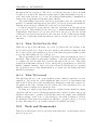
2.1.4
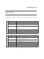
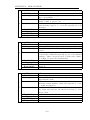
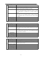
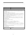
Risk Analysis
We have made a risk analysis for the project, which shows which risks might affect
the success of the project. For every risk we have a table which explains what the
risk is, how it might affect us, what we have done to avoid or limit the risk, and
what we can do if the risk occurs. Then we have the probability and damage, which
show in numbers from 1 to 10 how serious they are. 1 meaning not likely to happen
/ non-critical, 10 meaning very likely to happen / the damage is critical. The Risk
from 1 to 100, shows the product of these two, and gives an impression on how
serious the risk is and shows us what we should prioritize. The detailed risk analysis
is shown in Appendix A. Table 2.2 shows a summary of the risk analysis.
Risk
Illness or other
unexpected absence
Too much to do
in other subjects
Lack of materials
Internal conflicts
External
conflicts
Internal misunderstandings
External misunderstandings
Security problems
Don’t know how
to use development tools
Responsibility
Probability
Damage
Risk
4
6
24
everyone
6
6
36
everyone
2
4
8
secretary
2
6
12
everyone
2
8
16
customer contact
2
4
8
everyone
3
7
21
everyone
6
8
48
system architects
8
6
48
everyone
Table 2.2: Risk summary
9
CHAPTER 2. PROJECT MANAGEMENT
2.2
Sprints
For our project we are using Scrum, an agile software development method. A wider
explanation of Scrum can be found in Section 3.2.1. An essential part of Scrum is the
sprints, and in this section we will explain the sprint meetings and how we organize
them.
2.2.1
Sprint Planning Meeting
Every sprint starts with a planning meeting. In this meeting, the team members
decide what we will produce during the sprint. We make these decisions based on
the product backlog.
When we have decided what to accomplish, we break the work down into more
manageable tasks. These tasks should not be too large, as they should be possible
for one team member to finish in a timely manner. Some tasks, however, will remain
large. These tasks are typically related to documentation.
After breaking down the work, we distribute the tasks among the team members.
The distribution will be based on how long the tasks will take. Each team member
looks at each task and gives a time estimate, then the team tries to reach consensus
about the estimate. With time estimates, we ensure a fair distribution and lower
the probability that any team member will have a lot more work to do than the
others.
The tasks agreed upon become the basis of the sprint backlog, which is a detailed
overview of the tasks and how long they will take to finish.
2.2.2
Daily Scrum
Although this meeting is normally performed every day during a sprint, we have
decided we will have four meetings every week. Since the team members all have
different lectures at different times, it is difficult to find room for more meetings.
The meetings will be held at the same time and location every day, except on
Thursdays. The location is room 521 in the P15 building at NTNU. On Tuesdays,
Wednesdays and Fridays the meeting will be held at 09.15, and at 10.15 on Thursdays. There will be no waiting for team members that are late.
The meetings will last about 15 minutes, and will be performed while standing
in a semicircle around the planning board. This is because the daily scrums are
supposed to be short and to the point, and the planning board shows the sprint
plan and reminds everybody of the work that needs to be done. All stakeholders are
welcome to attend these meetings, but only the scrum team and the product owner
are allowed to talk.
The team members will answer to three questions during this meeting:
1. What have you done since yesterday?
2. What are you planning to do today?
3. Do you have any problems preventing you from accomplishing your goals?
10
2.3. PROCEDURES FOR QUALITY ASSURANCE
After the meeting, the Scrum Master and other team members who choose so, will
talk to members who answered anything but no to the third question and try to
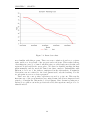
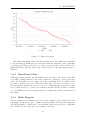
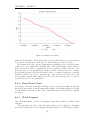
help. With these daily scrums, the state of progress is monitored. We present the
sprint backlog tasks and the progress in the sprint burn down chart. It gives us a
visualization of the work remaining and how our progress relates to the plan.
2.2.3
Sprint Review Meeting
This meeting is held after each sprint. In our project, this means 14 days after the
planning meeting. In this meeting we discuss the work we have done in the sprint.
We review both the completed work and what was not completed. If it is possible,
we try to have the customer present at these meetings. This way, they can see
how the project is progressing. If we have any completed work done, we can also
demonstrate this to the customer. They are also welcome to comment on our work,
offer suggestions on what they want us to do next and voice their opinion if there is
something they are not happy with.
2.2.4
Sprint Retrospective
After the review meeting, which focuses on the work itself, we have a retrospective
meeting. The intention of this meeting is to work on improving the process. The
team members are the only participants and will discuss different aspects of the
sprint, such as: What went well? What did not? Is there anything that can be
improved in the next sprint?
2.3
Procedures for Quality Assurance
The purpose of this part is to define the routines the project group implemented to
assure a high quality in the end result of the project.
2.3.1
Response Time
No formal agreement is made with either the supervisors or the customer, but we
have made it clear that we will respond as fast as we can. The group members have
exchanged phone numbers and MSN Messenger addresses, so contacting each other
quickly is no problem.
2.3.2
Customer Meetings
No formal agreement has been made, but we aim to have a meeting at least every
other week. We have also made it clear to the customer that they can visit us to
observe the Scrum meetings or for any other reason they might want to. Notice
shall be given at least the day before the meeting is held.
11
CHAPTER 2. PROJECT MANAGEMENT
2.3.3
Supervisor Meetings
We have scheduled to have a meeting with the supervisors once a week. Minutes from
the last supervisor and customer meeting will be attached to the invitation, which
will be sent before 12:00 the day before the meeting will be held. The invitation will
also include the agenda for the meeting, phase documents and the status report.
2.3.4
Coding Guidelines
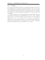
Our group has chosen to adopt the Java coding conventions as published by Sun[1].
Some important points are summarized in Table 2.3.
Rule
Constants are all upper-case. If consisting of several words, they are separated
by underscore.
Other identifiers consisting of several
words are separated using mixed case
— with the first letter of each word in
upper-case.
Class names are named with nouns,
and begin with upper-case letter.
Methods are named with verbs, and begin with a lower-case letter.
Example
VERSION NUMBER
SeniorDoctor,
getSumOfWorkingHours()
Person
makeSchedule()
Table 2.3: Some important coding guidelines
2.3.5
Subversion Procedures
To enable effective collaboration, avoid conflicting changes, and to make sure every
project member has access to the latest version of the documents and code, we have
set up a Subversion repository. See Appendix B for information on how to access
the repository.
The following guidelines shall be followed.
• Before starting work, perform an SVN update.
• Sort out any conflicting changes.
• Do not commit code that breaks the build / report rendering.
• Commit frequently.
• Write good commit messages describing the modifications.
• Do not add unnecessary generated files (binary Java class files / different
LATEX generated files). One exception is the report.pdf, which can be uploaded whenever a related document is updated.
12
CHAPTER
3
Preliminary Studies
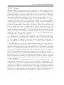
To try and resolve some concerns and get a better understanding of the project
at hand, we did some preliminary work. This chapter will explain what the current
situation is, and how it helps us how to proceed with the project. The tools we are
most likely to use throughout the process are also described.
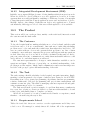
3.1
The Situation Today
The current situation, when it comes to scheduling programs and algorithms, must
naturally be considered in a project of this kind. Several questions need to be
answered before we start implementing, such as whether there is a need for the
project at all — maybe existing programs already fulfill the customers requirements,
and if there is a need, what algorithms have already been developed that can be used
to solve these problems. Not considering such questions can result in our project
spending time reinventing an existing solution.
3.1.1
Existing Programs
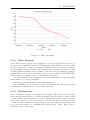
There are several commercial programs in the field of scheduling on the market
as this is being written. However, they do not cover the needs expressed by the
customer for this project. Some are designed to ease the task of scheduling by
helping the user identify possible errors or problems rather then actually scheduling.
One example is Time Tracker from Asgard Systems Inc1 .
Others are designed to ease self scheduling and interoperability between HR
systems2 . Furthermore, most are designed for scheduling shifts for nurses rather
than doctors. While the principles are transferable, this involves domain differences
which may require costly adaptation work. General schedulers are available3 , but
these are designed to be utilized in a large field of businesses, and will require much
work to adapt to hospital use.
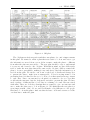
As an example, consider the Visual Staff Scheduler[2], a scheduling tool boasting
a wide range of positive feedback from the healthcare industry. It allows the user
to add attributes such as certifications and specialties to employees; it tracks the
employees’ total working hours so far in a period, as a percentage of a total workload
1
http://www.asgardsystems.com/
http://www.res-q.com/
3
http://www.timeclockplus.com/
2
13
CHAPTER 3. PRELIMINARY STUDIES
if desired; it lets you group employees who should ideally work together; it lets you
export the resulting schedule, easing distribution. It reduces errors and conflicts,
and reduces overtime expenses. While these are all helpful functions which our
customer might like, this system does not perform the primary function desired by
the customer, namely automatic and flexible scheduling.
The customer reports previously having looked at market solutions such as those
supplied by KDO Consulting 4 and Everett Consulting 5 , with unsatisfactory results.
As such, considering the costs involved for the customer, a tailor-made solution seems
to be a good solution.
3.1.2
Algorithms
The problem in question appears to be a constraint satisfaction problem, but also
an optimization problem, referring to the requirements for fairness and the junior
doctors’ appointment to a supervisor. Scheduling problems have been explored for
some time as a part of the field of operations research[3]. Reports exist of iterative
algorithms designed to solve similar problems [4], and of linear programming[5] being
used with success in optimizing nurse scheduling [6]. A similar approach utilizing
these findings seems viable.
Operations Research (OR) and Artificial Intelligence[7] have long been seen as
alternative, and very different, approaches to solving real world optimization problems, such as scheduling. In OR, the general idea is to reach a high level of efficiency
in algorithms, whereas AI prefers a high level of generality, making the algorithms
capable of solving a wider range of problems, and also enables the program to consider a wider range of possible solutions. There has been research into combining the
best of both worlds [8]. As mentioned in the previous paragraph, this is a constraint
satisfaction problem, in the form of shifts that must be filled, a limited number of
fillers for these shifts, a limited amount of shifts allowed for each person, and a minimum amount of shifts for each person. Added to this are the constraints on fairness
and the desire to have each junior doctor linked with a senior doctor supervisor. It
can in other words be considered a constraint satisfaction problem (CSP)[7], with
optimization playing a role in considering the value of several possible solutions.
Basing ourselves in constraint programming, combining it with OR as necessary [9]
should give us much freedom when it comes to defining the problem by ways of
constraints, while giving us a large base in the form of algorithms and research from
operations planning.
The problem can be considered a job shop scheduling problem[10] (JSSP), where
n jobs are to be scheduled on m machines, with a number of constraints. There are
n tasks, which must be completed by m individuals, with various constraints on
time (one individual can only work constantly for so long) and ability (certain tasks
are to be performed by senior doctors, others by junior doctors). The tasks also
need to be done in a certain order, with many in parallel, through the week. In
our case, two ”machines” of different kinds are to be set to each job, with a certain
connection between ”machines” being preferable. There are algorithms designed to
solve JSSPs, and they can probably be tweaked to our needs. The List scheduling
4
5
http://www.kdo.no/
http://www.everettsoftware.com/Roster.html
14
3.2. FRAMEWORKS USED IN THE PROJECT
algorithm by Graham is one of them[11]. The job shop problem is generally NPComplete[5]. However, by using heuristic algorithms which take advantage of the
special properties of this problem, the running time may be improved.
The 0-1 knapsack problem[5] may be considered as a model for the problem, or
part of it. The problem is fitting senior and junior doctors with a number of tasks
each period, with them only being able to do one task each period, and the junior
doctors preferring the same tasks as the doctors. There is a pseudo-polynomial time
dynamic algorithm[12] that solves the general 0-1 knapsack problem. However, this
does not seem as a particularly useful modeling at the moment, and it may simply
be complicating the problem further. The JSSP seems to be a more intuitive fit.
For choosing optimal schedules, as factors such as the connection between the
junior doctors and their supervisors for the period may vary between acceptable
solutions, linear programming may be used. Linear programming is a technique
for optimizing linear equations, subject to various linear inequality and equality
constraints. On a standard form, there are several algorithms designed to solve such
problems, such as the Simplex algorithm [5], or the ellipsoid method[13].
3.1.3
St. Olavs Hospital IT Systems
There is a strict policy on what kind of software is allowed on the systems at St.
Olavs hospital. It is not allowed to run programs which are not previously approved
for the system, and installed by the IT department. Hemit6 is the IT department
in charge of the IT systems in St. Olavs. They are responsible for controlling that
new programs are necessary, and safe for the systems. This might limit our ability
to test the program in the St. Olav system, as there is a processing time before the
system can be approved. As the program is not developed yet, it is also problematic
to get the unfinished application approved while testing.
Because of this, we plan to set up the database and web server in a separate web
hotel account, owned by one of the project members. This is not an acceptable final
solution, as the server will require maintenance to be usable — which is beyond the
scope of this project. This means that the customer will have to maintain such a
server on their own.
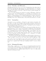
3.2
Frameworks Used in the Project
Several frameworks are available in the field of systems development, and are able to
reduce development time for several frequently used software solutions. This section
introduces those we found to likely be useful to us in this project.
6
http://www.hemit.no
15
CHAPTER 3. PRELIMINARY STUDIES
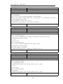
3.2.1
Software Development Model
Figure 3.1: The Scrum Process (adopted from Softhouse.se)
Initially there were two development models we considered for this project: the
waterfall method and Scrum. Tshe waterfall method is old, but still in use by a
lot of companies. With regards to software development however, most agree that
the waterfall method is a bad one. The sequential stages simply do not fit software
development. The method allows for little flexibility in a business that requires
much of it.
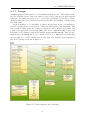
Scrum is an iterative and incremental planning and execution method for software development, and is based on the Agile Manifesto[14]. With Scrum, one has a
series of incremental work periods called Sprints. The sprints in our project last for
two weeks each. During a sprint, the team works on the goals set at the beginning
of it, at the sprint planning meeting. See Figure 3.1 for a nice illustration of the
Scrum method.
The reason why we chose Scrum to be our method, and not the waterfall method,
is because Scrum has many advantages for our project. Scrum helps the group
members monitor each others work and efforts. If a team member is not doing their
part, or needs some help with a task, it is discovered much earlier than what would
be the case when using the waterfall method. Frequent inspection of status is also
16
3.2. FRAMEWORKS USED IN THE PROJECT
handy. It makes it easier for us to see how far along we are in the project, and will
deliver results early. This way, the customer will have greater insight into our work
as well. With a traditional method, it would take longer for the customer to see any
working code since the implementation phase is one of the later ones. The customer
might also add or change the requirements. With the waterfall method, we would
have to do much of the preparation all over again. With Scrum, most of this work
is avoided.
3.2.2
Choice of Programming Language
Faced with the decision of programming language to use, our group primarily considered C# and Java.
Our group consists of 5 people who have used Java extensively in their own
projects, at university, and some at work. None of the group members have experience with C#.
C# would give us easy drag and drop components for integration with the Microsoft Outlook calendar, which the doctors use, but every group member would
need to learn C# to program in it. In Java, we will have to find a way to export
our generated schedules in a format that Microsoft Outlook can import, probably
iCal. This is very much feasible, as we will not need to implement the whole iCal
specification, in fact simple non-recurring events without time zone data will cover
our needs, and these can be generated from a template. If more complex events
prove necessary, Java libraries are available.
Our group has previous experience using Java frameworks, libraries and database
interfaces, which will speed up development tremendously.
We concluded that using Java for this project would yield a higher probability
of success, because it would not require us to learn a lot of new language idioms and
libraries for very little gain.
3.2.3
Database
Our database needs for this project are connected to our need for a system where
every employee can see their own working schedule, without using a specific computer. To make the data accessible from several locations, one easy way is to use
a database management system (DBMS). There are several different options, but
as our needs for data storage and advanced queries is limited, we do not need to
find an ”optimal” choice of DBMS. Obvious options are MySQL, PostgreSQL and
Apache Derby.
MySQL7 is a relational database management system, produced by the Swedish
company MySQL AB, a subsidiary of Sun Microsystems. It is under GNU General
Public License, which means everyone is free to use it, free of charge.
As we mention in Section 3.2.4, we are going to use Hibernate to ease the connection between our class hierarchy and the database. Hibernate supports all the
DBMS’es we considered, and does therefore not limit our choice of DBMS.
We chose MySQL because we are already familiar with it, both from school
projects and personal projects. We have also observed that it is the most common
7
http://www.mysql.com/
17
CHAPTER 3. PRELIMINARY STUDIES
DBMS provided by different web hosting companies, which gives the customer more
options when searching for a web host should they decide to deploy Khronos.
3.2.4
Hibernate
We are planning to utilize Hibernate for persistence in this application.
Hibernate is an open source framework[15] for database usage in Java. It greatly
simplifies, and to a large extent automates, the often tedious transformation between Java objects and database tables and table relations. It provides solutions for
caching, transactions and other features that are not so easy to implement. Hibernate allows the programmer to use plain Java objects with few restrictions.
An interface between Java logic and database tables is generally tedious and time
consuming to code, so it makes sense for our group to utilize an already available
and user friendly framework, rather than to create our own reimplementation. Hibernate seems to generally garner positive feedback from users compared to other
frameworks[16], at least for low data intensity applications[17], which this product
is expected to be. Reference material is readily available both on the web and in
book stores. Familiarity with Hibernate also appears to be a useful skill to have in
the future, career wise.
3.3
Tools Used in the Project
We found several tools intended to aid in various software projects that appeared
useful to us. In this section are introductions to the ones we chose to examine
further, and tried to utilize.
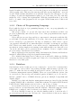
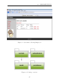
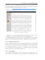
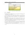
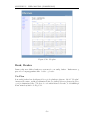
3.3.1
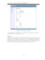
Trac
Trac8 is an open source, web-based project management tool. As well as being able
to track milestones, tasks and bugs, it has an interface with Subversion as well as
a Wiki. Figure 3.2 shows a screen shot of active tickets in an early phase of the
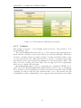
project.
We had first planned to use Trac for tracking the Scrum and its backlog, but
the Trac installation provided by our department at NTNU has some limitations,
making it hard to fit this tool to our development model. Section 3.3.2 describes
the tool we will use for tracking the Scrum process.
We will be using the SVN module of Trac, which allows browsing the project
files with version history available using a web interface. Also, the Wiki will be used
for simple information sharing, such as links to websites for hour registration and a
group calendar.
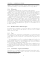
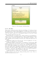
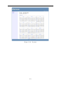
3.3.2
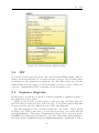
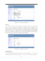
VersionOne: Agile Team Edition
VersionOne9 is a tool designed for helping teams digitize Scrum artifacts, and to
keep track of the project on-line. Figure 3.3 shows part of a screen shot from this
8
9
http://trac.edgewall.org/
http://www.versionOne.com
18
3.3. TOOLS USED IN THE PROJECT
Figure 3.2: Screenshot of Trac
service, with a part of the storyboard during sprint 4.
Some say that such tools can be a bad idea, as it makes the group adapt the
process to the tool, and not the other way around. This was discussed, and we found
out that the benefits of using the tool are larger. As we do not have an assigned
office, we do not have our own white board to track the Scrum process. We could
of course have used a wall in one of the rooms in the P15 building, but we risk that
the room is taken when we need to hold Scrum meetings, as well as ”funny” people
moving tasks around randomly. Another clear benefit is, as this is on-line, everyone
has access to it from wherever they are. Because we are taking different classes, it
is often hard to work together all day. By tracking the progress on-line, everyone
will be able to see who is doing what.
This is a commercial product, with license requirements. They do, however,
provide a 1-year free account for groups up to 10 persons. This enables us to use
this tool without any extra costs, except for the time spent to learn it.
3.3.3
Apache Tomcat
As the program is being implemented as a web application, and we want to develop
using Java, we need an application server / servlet container. There are several
open-source solutions available to suit our needs: Apache Tomcat, GlassFish and
Jetty are three options. They are all free to use. A list of servlet containers are
described in [18]
Some of the group members have used Apache Tomcat before, and this is why
we chose to use Tomcat. When developing web-applications in Java, the way to do
19
CHAPTER 3. PRELIMINARY STUDIES
Figure 3.3: Screenshot from VersionOne: A part of the storyboard
it is the same between the different servers. This means it should not be a problem
if we choose to change the server — we will only have to set up the configuration
again, and most of the code will stay unchanged.
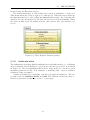
3.3.4
Balsamiq Mockups
Designing the graphical user interface (GUI) is an important process and needs
careful consideration. One way of making the process easier is by using a mockup
tool. A mockup is usually a scale model of a design used for demonstration, teaching
or evaluation of the design. There are many mockup tools available on-line and free
to use. Using such a tool is a nice way to illustrate early thoughts on the GUI. It
is much easier to make changes digitally than drawing on a piece of paper. With a
mockup tool, the different images also get much more consistent.
The flagship product of Balsamiq Studios is their mockup tool. It can be used
free in a browser, and it exports the mockup as a XML text so it can be imported
again on your next work period. It is easy to use, it is understandable, and it has
the necessary tools and images we need for our project. Those are the main reasons
why we have chosen this tool to work with.
3.3.5
Integrated Development Environment (IDE)
For writing Java, there exist several different IDE’s. Eclipse, NetBeans and IntelliJ
IDEA are the three most used ones. While Eclipse and NetBeans are open source
and free to use, IntelliJ IDEA is proprietary. As we have no economy for buying
licenses for different software, IntelliJ IDEA is not considered an option.
NetBeans is developed by Sun Microsystems, and is offered as a bundle when
20
3.3. TOOLS USED IN THE PROJECT
downloading the Java SDK from Sun. It supports different aspects of Java development, with built-in support for Subversion, Hibernate, Swing and other relevant
technologies. It also has a convenient plugin for drawing UML diagrams. NetBeans
could provide a great tool for our development, as we are to use these technologies.
Eclipse is the programming tool we have been encouraged to use from the start
in NTNU, and therefore also the one we are most familiar with. It supplies a vast
range of plugins for different purposes - for example Subversion, Hibernate and
Swing. This means that if we set up Eclipse in a proper way, it will be able to serve
our needs.
We have chosen to use Eclipse as the main IDE, with support from some NetBeans plugins. The developers are, however, free to use whichever tool they find
suited for their needs.
21
CHAPTER 3. PRELIMINARY STUDIES
22
CHAPTER
4
Requirement Specification
The requirement specification chapter gives a detailed description of all the requirements which must be fulfilled for the program to behave according to the wishes
of the customer. The chapter structure is based on the IEEE recommended practice
for software requirements specification[19]. It includes an introduction, an overall
description and both visual and textual use cases, which show how the user will
interact with the program. Use cases are also mapped to functional requirements.
We also include a section with non-functional requirements, which describe other
aspects of the program.
We considered gathering the requirements for this project to be of vital importance, as well as highly challenging. Misunderstanding or overlooking requirements
could result in a pointless or unusable product. This project came about as the
result of a perceived need from the customer, and a project that failed to attend
to that need, no matter how elegantly packaged or user friendly, would be a failed
project.
4.1
Foundation
This section contains a basic introduction to the requirement specification itself, as
well as the general structure of the requirements.
4.1.1
Purpose
The purpose of the requirement specification is to get a clear view of the requirements
of the program. It is important for the group to have a requirement specification
which is easy to read and understandable, and at the same time containing all the
requirements gathered for the group to get a better overview. This chapter will be
referred to again and again during implementation.
Obvious users of this specification are the customers at St. Olav and the project
group. Other users include the teaching supervisors and future users of the system.
4.1.2
Scope
The system is intended to make a flexible schedule for senior and junior doctors,
and the tasks they need to cover, which have to be distributed according to several
rules. The distribution must also be done fairly, it has to sum up the same working
23
CHAPTER 4. REQUIREMENT SPECIFICATION
hours for all employees. If a task does not have a doctor assigned to it, or if it has
more than one, the system must notify the user.
The program does not need to handle unplanned absence of doctors, sickness or
similar. This will be handled by the customer manually. There is almost never a
problem of another doctor not picking up the tasks that become unassigned. The
system will, however, notify the user about the unassigned task.
4.1.3
Overview
The rest of this chapter consists of an overall description of the product and the
requirements themselves. In the overall description we describe some aspects of
the product, for example defining the users. In the requirements section we list
the functional and non-functional requirements, along with use case diagrams and
textual use cases.
The sections are organized as follows:
4.2 Overall description
4.2.1 Product perspective
4.2.1 User interface
4.2.2 Product functions
4.2.3 User characteristics
4.2.4 Constraints
4.3 Specific requirements
4.3.1 Functional requirements
4.3.2 Non-functional requirements
4.3.3 Use cases
4.2
Overall Description
This section contains high level requirements, including requirements for the system
on which the system is to be run.
4.2.1
Product Perspective
The product is not supposed to communicate or cooperate with any existing systems,
except for being able to export data to iCal format, which makes it possible to import
data into calendar software, like MS Outlook. This means the product is completely
self contained.
The iCal format is described in RFC2445 [20].
24
4.2. OVERALL DESCRIPTION
User Interface
The user will operate the system using a computer running Windows XP or newer
— with screen, mouse and keyboard. The system will require a screen resolution
above 800x600 pixels.
The system will have two interfaces:
• The planning interface, which will have one user at a time. This is the part
where scheduling variables are set up, and changes to the schedule can be
made.
• The overview interface, which will have n users at a time, where the user can
see the schedule, but not do any changes.
The user interface language shall be in Norwegian, as this is required for software
used in Norwegian hospitals.
4.2.2
Product Functions
The system shall be able to set up a valid schedule for working hours in the hospital,
given constraints input by the user. When this schedule is ready, users accessing
the overview interface should be able to see the given schedule.
4.2.3
User Characteristics
The different users of the system are doctors and secretaries, or any other employee
in the schedule.
Hospital employees have to use several different computer systems every day, and
are not necessarily interested in learning yet another one. This increases the need
for a user friendly and intuitive user interface.
There are two defined user categories:
• Schedule master: This user will have access to the scheduling interface. He
will set the constraints, and generate the plans. This could be any employee,
but the role will be fixed.
• Employee: This is everyone else. They will only have access to show and print
the finished plans.
4.2.4
Constraints
• The user interface has to be presented in Norwegian, according to rules for
software in Norwegian hospitals.
• The project has a finite deadline at November 19, 2009.
• The project group has five members with varying experience with developing
software. There will not be any more resources allocated.
25
CHAPTER 4. REQUIREMENT SPECIFICATION
4.3
Specific Requirements
This section contains the specific requirements for the system, both functional and
non functional, as well as use cases corresponding to the functional requirements.
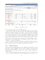
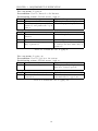
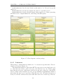
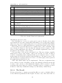
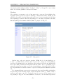
4.3.1
ID
F01
F02
F03
F04
F05
F06
F07
F08
F09
F10
F11
F12
F13
F14
Functional Requirements
Description
The user can define a plan.
The user can make changes in a generated plan.
The user can attach two doctors for a given period.
The user can define a doctor in the system.
The user can set availability for a doctor for a period of time.
The user can define rooms/departments.
The user can define tasks.
The user can assign a doctor to a fixed task.
The user can choose to view the plan for everyone or just himself.
The user can choose to view the plan for different time scopes; day,
week, month, etc.
The user can print the schedule.
The user can log in.
The user can log out.
Optional
The user should be able to export data to the iCal format.
Table 4.1: Functional requirements
26
Priority
High
High
Medium
High
Low
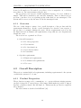
High
High
Medium
Medium
Medium
High
High
High
Low
4.3. SPECIFIC REQUIREMENTS
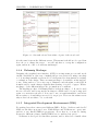
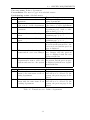
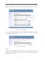
4.3.2
ID
NF01
NF02
NF03
NF04
NF05
NF06
NF07
NF08
NF09
NF010
NF11
Non-functional Requirements
Description
There must exist a friendly user manual and a proper documentation of the system design.
The schedule must be set up within reasonable time after specifying
all constraints.
It should be easy for the user to insert correct input.
The application must be simple and easy to understand.
The program should allow undo actions.
The program must not require external components under proprietary licenses.
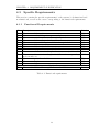
The application must distribute the ”on-call”-hours fairly, depending on the working hours.
The application must make sure that all the tasks of the week are
covered and notify the user if there is a task that has not been
covered or if a employee is double booked.
The application should display a schedule in a printable format.
The application must discern between the different working hours
of the specialists and the rest.
The application must be able to discern between the different tasks,
as some must be done several times a week while some only once a
week.
Priority
High
Low
Medium
High
Low
High
High
High
High
High
High
Table 4.2: Non-functional requirements
4.3.3
Use Cases
Figures 4.1 to 4.3 show use case diagrams used in the process of writing the textual
use cases.
Tables 4.3 to 4.10 show the textual version of these use cases.
27
CHAPTER 4. REQUIREMENT SPECIFICATION
Precondition:
Connected to the
Internet,
logged in
Defining the domain and
setting up the schedule
Define locations/
rooms
Define a task
Define a doctor
The user can make
changes to the plan
Schedule master
Define a plan
<<extend>>
<<extend>>
<<extend>>
Assign fixed
tasks for a doctor
Set availability for
a doctor
Attach two
employees for a
given periode
Figure 4.1: Defining the domain
28
4.3. SPECIFIC REQUIREMENTS
Preconditions:
Connected to the
Internet
Log in/Log out
Log in
Schedule master,
employee
Log out
Figure 4.2: Logging in and out
Preconditions:
Connected to the
Internet, Logged
in, A plan marked
as final exists
Viewing a scheduled plan
Choose time
scope
<<extend>>
<<extend>>
Print
View plan
Employee
<<extend>>
<<extend>>
Choose to view the
plan for everyone or
just yourself
Figure 4.3: Viewing a scheduled plan
29
Export to iCal
CHAPTER 4. REQUIREMENT SPECIFICATION
Use case name: Logging in
Precondition: User is connected to the Internet
Participating actors: Schedule master, employee
Steps Action
Expected response
1.
User goes to the Khronos page
The Log in screen is displayed
2.
The user enters user name and The front page is displayed
password, and pushes the log in
button
Exceptions
Steps Problem
Solution
1.1
The user is not connected to the Contact hospital system admin
Internet
1.2
The server is down
Contact Khronos system admin
2.1
The user enters wrong user name Contact Khronos system admin
and/or password
to retrieve the user name and/or
password
Table 4.3: Textual use case: Logging in
Use case name: Logging out
Precondition: User is logged in to the system
Participating actors: Schedule master, employee
Steps Action
Expected response
1.
User chooses to log out
The log in screen is displayed, the
user is no longer logged in
Exceptions
Steps Problem
Solution
1.1
The user has lost the Internet There is a time out, so you will
connection
automatically be logged out
Table 4.4: Textual use case: Logging out
30
4.3. SPECIFIC REQUIREMENTS
Use case name: Define a department
Precondition: The user is logged in as schedule master
Participating actors: Schedule master
Steps Action
Expected response
1.
The user chooses to define a de- The system displays the list of expartment
isting departments
2.
The user chooses if he wants to The system displays the page for
edit, remove or add a department edit, remove or add a department
3.
The user chooses to remove a de- The system displays the remove
partment
department page, with a confirmation dialog, go to 6
4.
The user chooses to edit a depart- The system displays the edit dement
partment page, go to 7
5.
The user chooses to add a depart- The system displays the add a dement
partment page, go to 8
6.
The user chooses yes or no
If yes, the department will be removed from the system. If no, the
action is aborted and the previous
page is displayed
7.
The user makes the changes he The system is updated with the
wants and chooses to save changes new changes and the previous
page is displayed with the new
changes in the list
8.
The user writes the name of the The new department is saved in
department he want to add to the the system, and the previous page
system and saves it to the system is displayed with the new department in the list
Exceptions
Steps Problem
Solution
4.1
The user chooses to edit a depart- Department names are unique, so
ment to the same name as an ex- this will not be allowed by the
isting department
system, the previous page is displayed
5.1
The user chooses to add a depart- Department names are unique, so
ment with the same name as an this will not be allowed by the
existing department
system, the previous page is displayed
Table 4.5: Textual use case: Define a department
31
CHAPTER 4. REQUIREMENT SPECIFICATION
Use case name: Define a task
Precondition: The user is logged in as schedule master
Participating actors: Schedule master
Steps Action
Expected response
1.
The user chooses to define a task The system displays the list of existing tasks
2.
The user chooses if he wants to The system displays the page for
edit, remove or add a task
edit, remove or add a task
3.
The user chooses to remove a task The system displays the remove
task page, with a confirmation dialog, go to 6
4.
The user chooses to edit a task
The system displays the edit task
page, go to 7
5.
The user chooses to add a task
The system displays the add a
task page, go to 8
6.
The user chooses yes or no
If yes, the task will be removed
from the system. If no, the action
is aborted and the previous page
is displayed
7.
The user makes the changes he The system is updated with the
wants and chooses to save changes new changes, and the previous
page is displayed with the new
changes in the list
8.
The user writes the name of the The new task is saved in the systask he wants to add to the sys- tem, and the previous page is distem, and saves it
played with the new task in the
list
Exceptions
Steps Problem
Solution
4.1
The user chooses to edit a task to task names are unique, so this will
the same name as an existing task not be allowed by the system, the
previous page is displayed
5.1
The user chooses to add a task task names are unique, so this will
with the same name as an existing not be allowed by the system, the
task
previous page is displayed
Table 4.6: Textual use case: Define a task
32
4.3. SPECIFIC REQUIREMENTS
Use case name: Define an employee
Precondition: The user is logged in as schedule master
Participating actors: Schedule master
Steps Action
Expected response
1.
The user chooses to define an em- The system displays the list of exployee
isting employees
2.
The user chooses if he wants to The system displays the page for
edit, remove or add an employee edit, remove or add an employee
3.
The user chooses to remove an The system displays the remove
employee
employee page, with a confirmation dialog, go to 6
4.
The user chooses to edit an em- The system displays the edit employee
ployee page, go to 7
5.
The user chooses to add an em- The system displays the add an
ployee
employee page, go to 8
6.
The user chooses yes or no
If yes, the employee will be removed from the system. If no, the
action is aborted and the previous
page is displayed
7.
The user makes the changes The system is updated with the
he wants, and chooses to save new changes and the previous
changes
page is displayed with the new
changes in the list
8.
The user writes the name of the The new employee is saved in the
employee he wants to add to the system, and the previous page is
system, and saves
displayed with the new employee
in the list
Exceptions
Steps Problem
Solution
4.1
The user chooses to edit an em- Employee initials are unique, so
ployee to the have the same ini- this will not be allowed by the
tials as an existing employee
system. The previous page is displayed
5.1
The user chooses to add an em- Employee initials are unique, so
ployee with the same initials as this will not be allowed by the
an existing employee
system. The previous page is displayed
Table 4.7: Textual use case: Define an employee
33
CHAPTER 4. REQUIREMENT SPECIFICATION
Use case name: Define a plan
Precondition: The user is logged in as schedule master
Participating actors: Schedule master
Steps Action
Expected response
1.
The user chooses to define a new The system displays the define
plan
plan page
2.
The user chooses time period to The system displays the changes
make the plan for and makes that the user makes
other optional specifications for
the plan, go to 8
3.
The user sets availability for an The system marks the changes
employee
made in the plan, go to 8
4.
The user chooses to attach two The system displays the attach
employees, go to 6
two employees page
5.
The user chooses to assign fixed The system displays the fixed
tasks to an employee, go to 7
tasks for an employee page
6.
The user chooses which employees The system marks them as atto attach, time period, and saves tached in the plan and displays
the changes, go to 8
the previous page
7.
The user chooses which employee The system marks the fixed tasks
to assign fixed tasks to, which in the plan and displays the prefixed tasks the employees should vious page
have, and saves the changes
8.
The user marks the plan as final The plan is marked as final and is
available for viewing.
Exceptions
Steps Problem
Solution
3.1
The user sets availability for The system will notify the user
an employee and this results in about under-bookings
under-booking of a task
4.1
By attaching two employees a The system will notify the
task is left under-booked or a doc- user about under-bookings and
tor gets double-booked
double-bookings
5.1
A doctor gets double-booked
The system will notify the user
about double-bookings
Table 4.8: Textual use case: Define a plan
34
4.3. SPECIFIC REQUIREMENTS
Use case name: Make changes to the plan
Precondition: The user is logged in as schedule master
Participating actors: Schedule master
Steps Action
Expected response
1.
The user chooses, make changes The system displays the change
to plan
plan page
2.
The user make the changes he The system notifies the user if
wants
there are any problems with the
new changes
3.
The user marks the new plan as The system notifies the user that
final
the plan is marked as final
Exceptions
Steps Problem
Solution
2.1
The user makes a change to the The system handles this by notiplan, which results in double- fying the user so that the user can
booking of a doctor or under- correct this
booking of a task
Table 4.9: Textual use case: Make changes to the plan
Use case name: View plan
Precondition: Logged in as schedule master/employee, a plan is marked as final
Participating actors: Schedule master, employee
Steps
Action
Expected response
1.
The user chooses to view the plan The system displays the plan for
a default time scope for every employee
2.
The user chooses to changes the The system displays the plan for
time scope
the specified time scope
3.
The user chooses to view the plan The system displays the plan for
for just himself
a default or specified time scope
for the employee logged in
4.
The user chooses to print the plan The system prints the plan
5.
The user chooses to export to iCal The system exports to iCal
Exceptions
Steps
Problem
Solution
1.1
A plan is not marked as final
Contact the schedule master
2.1
A plan is not marked as final for Contact the schedule master
the specified time scope
4.1
There is a problem with the Contact the Hospital system adprinter
min
Table 4.10: Textual use case: View plan
35
CHAPTER 4. REQUIREMENT SPECIFICATION
4.3.4
Testing
A test regime was designed at this point, to ensure that the final product would be
up to specifications. It was decided to perform unit testing on the code as it was
created during the various sprints. Integration tests were to be performed by the
coders as the different parts were integrated. As the sprints would not be planned
in detail until closer to them starting, exact test plans could not be created at this
point. One exception was the system test plan, intended to be run at the end of the
fourth sprint.
A system test plan was created, reflecting the system requirements. The tests
were designed to run at the end of the implementation process to test for bugs and
faults, as well as to verify the completion of the program, in accordance with the
requirements. A total of eleven tests were written, covering one or more functional
requirements, and in total covering all the non-optional functional requirements.
The plan can be found in Appendix E. The test procedures were deliberately vaguely
worded on the exact actions to be performed, as we at the point of requirement
specification had limited knowlege of the final form of the system.
36
CHAPTER
5
Sprint 1
This was the first sprint of the project. There were several tasks we chose to be
part of it, mainly making a graphical user interface example and implementing the
basics in architecture and logic.
5.1
Planning
The start of a project is very important. What we did in this sprint would lay
out the foundation on which we could continue the work in later sprints. We had
to make sure that we put what we found in the preliminary studies to good use,
and worked hard so both the customer and ourselves would be satisfied with the
progress.
5.1.1
Goals
The goal of this sprint was to have an initial draft for the graphical user interface
ready. We wanted to have it ready to show the customer in our next meeting to get
valuable input and comments. We also aimed to have some important foundations
of the program implemented at the end of the sprint. More trivial goals were also
to have the name and logo for the project made.
37
CHAPTER 5. SPRINT 1
5.1.2
Sprint Backlog
ID
Priority Description
Req.
2.1
2.2
High
High
2.3
2.4
3.1
3.2
4.1
1.1
1.2
5.1
6.1
5.2
5.3
Make the object model shell
Add methods to model
classes
High
Develop the object model
methods
High
Create scheduling class and
methods
High
Set up database
High
Set up and test Hibernate
High
Define the class hierarchy
Medium Make GUI mockups
Medium Research advantages and
disadvantages of choices in
GUI
Medium First draft of report
Low
Testing of scheduling, persistence and database
Low
Make the logo for the
project
Low
Name the project
Hours
used
6
2
Responsible
F01
F01
Hours
est.
6
2
F01
8
8
Petter
F01
2
2
Petter
F13
F13
None
NF04
NF04
1
8
8
2
4
1
8
8
4
4
Arve
Arve
Arve
Thorbjørn
Thorbjørn
None
NF02
34
1
40
3
Petter
Thorbjørn
None
2
2
Susanne
None
Sum:
2
80
2
88
Susanne
Petter
Petter
Table 5.1: Sprint 1 Backlog
5.2
Design
By using Balsamiq Mockups, we made a draft of what the graphical user interface
(GUI) would possibly look like, though changes were expected to be made before
the completion of the project. It was made for the customer to get an idea of the
interface which contained most of the functionalities we would implement. In our
next customer meeting we would show it to them and explain what our thoughts
were. Any feedback from the customer would be very valuable for us to continue
the process. Figure 5.1 shows a screenshot of the mockups tool.
There were some important things we needed to consider with the design of the
GUI. The usability aspect was obviously one of them. The definition of usability
according to ISO 9241-11[21] is: ”the effectiveness, efficiency, and satisfaction with
which specified users achieve specified goals in particular environments”.
The ISO 9241 also specifies: ”Effectiveness measures the accuracy and completeness with which users achieve specified goals. Efficiency measures the resources
expended in relation to the accuracy and completeness with which users achieve
goals. Satisfaction measures the freedom from discomfort, and positive attitudes
towards the use of the product.”
38
5.3. NAME AND LOGO
Figure 5.1: Screenshot of Balsamiq Mockups
So the effectiveness, efficiency and satisfaction are measurable. The GUI of our
program was to be rather simple, and the tasks done by the user not very extensive,
but we still planned to do some measurements.
Since the final product would take the shape of a web application, we reasoned
that the GUI would probably consist of simple tables, text fields and buttons. Objects that may distract the user from doing his or her task properly and efficiently,
was to be kept to a minimum.
Even though we did not plan to have many different screens for the user to
view, in terms of navigation there were some things that needed to be emphasized.
A page must always let the user know where he/she is. The page must be clear
enough about its content so the user does not have to about the purpose of it. It
should also be clear where the user might navigate to from this page, and where the
user came from.
These were goals we tried our best to fulfill, and always kept in the back of our
minds when designing and implementing the GUI.
5.3
Name and Logo
When we started work on sprint 1, we thought that we should have a name for the
project. A name with relevance, but shorter and more catchy than the working title,
”Flexible Duty Roster for Doctors in Hospitals”, was desired. The name Khronos
was brainstormed during this sprint, and a logo was designed to reflect this name.
The logo was made after the project name, and a representation of time and
health was sought. Chronos was often represented by an old and wise man, but we
wanted our own interpretation. We wanted something that looked like it belonged
39
CHAPTER 5. SPRINT 1
at a hospital, combined with a time element.
5.4
Implementation
We focused on setting up the skeleton for the program. The different classes representing the domain were specified, some relations between these, and their constraints. The skeleton of the scheduling algorithm was made, but there was still a
lot of work to be done.
We implemented the basic logic of the program, using the Java Swing Framework.
This, however, proved useless, due to our last-minute changes in architecture. For
new computer programs to be allowed within the hospital environment, the software
had to be verified by the IT department. This could take a long time and could
not be done until the software was in its final form. Because of the time limit, we
wanted the customer to be able to use the program as soon as possible. Because of
this, it was decided to make the program a web application in Java. This was to
allow it to run on a server, without the limitations of the internal hospital rules.
5.4.1
Class Diagrams
At this point in time, the scheduling algorithm was not yet final. As such, the
domain model was still subject to changes. If we saw that we needed changes to suit
the scheduling algorithm, they would be reflected in the domain model. Therefore,
the class diagram in this chapter is lacking some details. Figure 5.2 shows the
package overview, and Figure 5.3 shows a more detailed view of the package model.
5.4.2
Packages
To keep the code organized, we split it into packages, which we thought were logically
separate. Model contained the domain model, persistence contained the classes
related to the database (via Hibernate), and scheduler contained classes used for
scheduling. As we made this, we had in mind that more packages could be added
later, as the web interface was planned to be defined in the next sprint.
5.4.3
Model
As shown in Figure 5.3, the domain consisted of Employees who work in a Department.
A Task is performed by a Position, and a Task belongs to a Department. By
adding more information in the next sprint, the final result would be mapping the
Employees to solve the different Tasks.
A Position in our domain was either a senior or junior doctor. From an object
oriented standpoint, it might seem strange not to make two subclasses SeniorDoctor
and JuniorDoctor inheriting the Employee-class. We, however, made it this way, so
that other departments, with other needs, may define a series of different employees.
In that way, Khronos could be able to schedule other domains than the medical one
as well. This was not a goal, but a possible bonus.
The task had some more attributes than shown in the class diagram. They were
omitted to make the diagram less cluttered. It was set to be performed on a series
40
5.5. TESTING
Figure 5.2: Class diagram: Package overview
of weekdays (one boolean per week day), starting at a given time, and with a given
duration. In addition, one could define a duration before and after the task, where
the employee performing the task is not assigned to other tasks. More detail to be
added in the next sprint.
5.4.4
Database Mapping
As Hibernate defines schema for the database based on annotations in the provided
classes, we do not provide an ER-diagram. The relations in the class diagram show
the same mapping between classes, where the classes correspond to entities/tables.
5.5
Testing
We did not have any formal testing in this sprint since not much more than basic functionality was implemented, but we did perform different tests parallel with
coding to ensure the coding so far behaved as expected.
5.5.1
Scheduling
In this sprint, we met with the customer to gather information about how the
scheduling is being done today, and what rules they are currently following, either
explicitly, or following anyway even though they may be unwritten. We created a
prototype to test the rules we gathered from the customer, and checked the output
41
CHAPTER 5. SPRINT 1
Figure 5.3: Class diagram: A closer look on the model package.
42
5.6. EVALUATION
to see if it was sensible, or if we needed more details. We decided we needed more
input from the customer and planned to gather that during the next sprint.
5.5.2
Persistence and Database
As Hibernate and the database were set up, we had to test that the relations were
working as intended. This was done by adding new entities, fetching them, editing
them, and persisting them again. The testing was not done formally, as the structure
of the model was not yet complete. The testing showed some minor faults that were
corrected underway.
5.6
Evaluation
In this section we show the burn down chart, and discuss how the work progressed
and how sprint process itself evolved.
5.6.1
Review Meeting
Only the team members were present at this sprint’s review meeting. There was
nothing to demonstrate at this early stage, but everybody explained the work they
had done in more detail than on the daily scrums. In plenum we discussed each
others work and the whole work progress. All this set the basis for the next sprints
planning meeting.
5.6.2
Burn Down Chart
Figure 5.4 shows the burn down chart for the first sprint. It shows that our estimates
were not perfect, but not that far off. All in all, the team members agreed we did a
good job on the estimates and sticking to the plan.
5.6.3
Work Progress
We did some research on the design, we implemented the skeleton of the program
including some basic methods and we did not deviate from the plan too much. There
were no problems we were not able to overcome, although it was a bit more time
consuming than we had planned.
We were positive that in the next sprint we would get much of the implementation
done. We would have a customer meeting at the end of the sprint where we would
present the work and show them many of the functions that was planned for the
final version.
We gathered requirements for the scheduling algorithm and implemented a prototype in order to compare our understanding to customer expectations.
5.6.4
Retrospective
In the retrospective meeting we agreed on a few things we needed to do better in
the next sprint. We had a few problems with VersionOne, and we needed to get
43
CHAPTER 5. SPRINT 1
Figure 5.4: Burn down chart
more familiar with this program. There was some confusion about how to register
tasks, and how to keep track of the progress and work hours. This resulted among
other things in a very poor burn down chart, since we added and removed tasks, and
registered work hours in the wrong place. We therefore handled tracking the first
sprint manually, and also made the burn down chart ourselves. Unfamiliarity with
different tools is one of the risks we anticipated in the risk analysis. Fortunately
VersionOne was not critical for the development itself, only the tracking. For the
second sprint we were now better prepared.
There were also some positive experiences we need to point out. This was the
first time any of the group members were using Scrum, but all were impressed and
gained good insight into this method of development. Since Scrum is getting more
and more recognition out in the professional world, this experience may prove to be
valuable indeed.
44
CHAPTER
6
Sprint 2
In the second sprint we decided to focus heavily on the implementation of the
program. Much of the basic foundations of the implementation was done in sprint
1, and in this sprint we expanded it greatly.
6.1
Planning
We planned to involve the customer more, now that the implementation was under
way. It was imperative that the scheduling algorithm was according to the customers
wishes, or else the resulting program would be unusable. We also planned to not
put much thought into the design of the graphical user interface in this sprint, and
rather focused on getting parts of the program up and running. We did perform
a customer meeting where we discussed the graphical user interface, but focused
mostly on the functions and not the presentation.
6.1.1
Goals
We aimed to have the graphical user interface functions, and also many functions
connected to scheduling, ready to show the customer at the end of this sprint.
45
CHAPTER 6. SPRINT 2
6.1.2
Sprint Backlog
ID
Priority Description
Req.
1.3
High
1.4
1.5
2.5
2.6
2.7
4.2
4.3
1.6
6.1
6.2
4.4
Make basic layout for the
web page
High
Make table for data input
High
Initial usability test with
customer
High
Expand the object model
shell (domain)
High
Extend the object model
methods
High
Expand the scheduler class
High
Set up the class hierarchy
High
Set up Tomcat
Medium Web page layout documentation
Low
Scheduling testing
Low
Object model testing
Low
Class hierarchy documentation (UML)
Hours
used
6
Responsible
NF04
Hours
est.
4
NF03
NF04
5
5
8
5
Arve
Thorbjørn
F01
2
6
Arve
F01
2
3
Arve
F01
None
None
NF03
18
18
8
6
31
22
14
8
Petter
Arve
Arve
Thorbjørn
F01
F01
None
4
4
5
2
2
5
Petter
Petter
Arve
Sum:
81
112
Susanne
Table 6.1: Sprint 2 Backlog
6.2
Implementation
In this phase, we set up the web application environment, and made a working
example. A screenshot can be seen in Figure 6.1. The package collection was
extended a bit, and the updated diagram is shown in Figure 6.2.
6.2.1
Scheduling
At this stage we expanded upon the prototype we made in the previous stage as
we gathered more scheduling rules and examples from the customer. We started
moving the scheduling into the main code base, and adjusted the model classes in
order to achieve this integration.
At this point the planner was able to make plans that obeyed the consecutive
working hour limits given in the Norwegian work environment regulations. In addition, some tasks at the hospital have requirements for rest before and after the task.
Functionality was added to allow the user to input this information and to have the
planner take it into account.
The planning algorithm takes as its input a start day, an end day, a set of
employees and information about their roles, a set of tasks and information about
when the tasks should be performed.
46
6.2. IMPLEMENTATION
Figure 6.1: Screenshot: Showing Employees
Figure 6.2: Package overview
47
CHAPTER 6. SPRINT 2
Figure 6.3: Class diagram: Package: servlets
Then it goes through the days, starting at the given start day, and for each
task to be performed that day, it tries to find an employee that can perform it.
An employee may be blocked from performing the task because he/she worked too
recently, or because of other duties.
6.2.2
Web application
The web application was set up, and worked nicely on a Tomcat server. It was
deployed as a .war file, and was therefore easy to deploy on different servers. The
database was still set up on a personal web hosting account belonging to a group
member. In the next sprint, we would work to get it set up on a server at IDI.
To make the web application, we configured the context to map different URLs to
different servlets. We made our own KhronosServlet, which extends HTTPServlet,
adding a few methods to ease the use of sessions and authentication. Our servlets
then extended KhronosServlet. This can be seen in Figure 6.3
48
6.2. IMPLEMENTATION
6.2.3
Servlets
The basic parts of the HTTPServlet are the methods doGet() and doPost(). These
handle the different HTTP requests, namely GET and POST. GET is used for most
requests, the static pages, and basic information retrieval. These are the requests
you send when you click a link. POST is used when you submit a form. They
can both include parameters, GET by specifying them in the URL, with a trailing
query (everything right of a question mark), and POST sends them in a way that
is invisible for the user. By passing parameters, and separating between GET and
POST, a servlet can be used in several ways. One example is shown in the sequence
diagram in Figure 6.7. The servlet named LoginServlet shows a login page when
doGet() is called, and validates supplied user credentials when doPost() is called.
Utils is a helper class, which the servlets use to access some information.
getLoggedInUser() checks if the current session has saved a user object. If this is
the case, then a user is logged in. locationHeader() is used to forward to any other
URL, within or outside the domain. checkLevel() determines if the logged in user
satisfies the specified AccessLevel, determining whether a user has the privileges
he needs or not.
6.2.4
Authentication
The authentication could be improved in the future, therefore it was placed in its
own package to be easilily replaced if needed. So far, there were two hard coded users
(master/master and slave/slave). Master was given access like a Schedule Master,
and slave access to view the plans (as a regular employee). This package is shown
in figure 6.4.
6.2.5
Model
The model was not changed a lot from the last sprint, but more details have been
added to the diagram. This is shown in figure 6.5. We were still open to change it
some more, as the Schedule part was taking time to develop, and naturally would
affect the domain model.
All classes were given default constructors and setter/getter pairs for every persistent variable. This is required to be able to use Hibernate.
As can be seen, Department was not yet connected to the model, but was meant
to be connected to Task. A task belongs to a specific department. We also planned
to connect Employee to Department, as each employee normally belongs in a given
department.
Task now contained a lot of methods to set and get different variables. We used
a boolean for every week day, to specify whether the task is performed on the given
day. These booleans were saved in the database, giving a column for every week day.
In addition, we provided convenient setters/getters using the Collections framework.
This enabled us to call getDays() to get a Set of days on which the task will be
performed, and setDays() to set all the days using one Set.
The class YearWeekDayPK was used to make a composite primary key in the Day
table of the database. This means that YearWeekDayPK in the Day table makes
49
CHAPTER 6. SPRINT 2
Figure 6.4: Class diagram: Package: authentication
50
6.3. TESTING
three fields, namely year, weeknumber and weekday. Weekday was an enumerable
type.
The classes Schedule and ScheduleRow were made for storing a generated schedule in the database.
6.2.6
Persistence
Persistence still only contained the class HibernateUtil, which sets up the Hibernate environment, and initializes the connection pool and session factory. We added
some methods, to keep a HibernateSession connected to each HTTPSession. When
a HTTPSession wants a HibernateSession, it calls the HibernateUtil.getSession(String
id), which returns the existing session if there is one, or creates a new one if not.
The id is the auto-generated id belonging to the HTTPSession. This is then put into
a HashMap, which keeps the HibernateSession alive until closeSession(String id)
is called with the same id. This method closes all the sessions, and is only called
when the server is shutting down.
6.2.7
Integrated Development Environment (IDE)
As we converted to making a web application instead of a Java Spring app, we
also changed the main IDE. NetBeans has very good built-in support for developing
web applications, with tools for modifying the database structure, and building and
deploying the web application itself. It can also control different web servers, like
Tomcat, so that building and running the newest version can be done in a matter of
seconds. It is also evident that the different UML tools NetBeans provide are better
than similar plugins for Eclipse.
6.3
Testing
In this sprint it was important to both test many new functions in the program
and also communicate with the customer about how a user will interact with the
program. During the development, we continuously used the system to verify new
functionality. A customer meeting was conducted to gather more requirements and
discuss our understanding of details of the task with the customer.
6.3.1
Graphical User Interface
We also had the initial usability testing with the customer. We did not focus on
the usability of the GUI itself, but rather on the functions we wanted to include in
the program which the customer would interact with. The customer, after getting
some explanations, approved and agreed on our thoughts on the functions a schedule
master and ordinary users would need.
6.3.2
Scheduling
As we worked on implementing the new scheduling rules gathered from the customer
we verified the output against their plan and our expected results. Some flaws were
51
CHAPTER 6. SPRINT 2
Figure 6.5: Class diagram: Package: model
52
6.3. TESTING
Figure 6.6: Class diagram: Package: persistence
Figure 6.7: Sequence diagram: Log in
53
CHAPTER 6. SPRINT 2
found and corrected this way.
6.3.3
Database
As we adjusted the model to contain the classes needed for scheduling we had to redo
some of the Hibernate mappings and write some new ones as well. This required
verification that we were storing the objects correctly and were able to retrieve them.
We wrote code to verify this.
6.4
Evaluation
In sprint 1 we laid the foundation of the program. It was easy to know what needed
to be done next, and we had a fairly good idea where we were in the process. In
sprint 2 it was different because of a number of reasons, though despite the problems
we managed to advance greatly with the implementation.
6.4.1
Review Meeting
Also present at this sprint review meeting was the customer. This gave us the opportunity to both demonstrate the completed work so far, and get valuable comments
which we needed for our further work.
As the burn down chart in Section 6.4.2 shows, not all of the planned work was
finished. Trouble with Tomcat made the ToDo higher in the beginning. Realizing
that we needed more time on the scheduling method in particular made it higher in
the end, and was also the reason that not all the planned work was completed. It is
clear that some of our estimates were wrong in this sprint, and that some tasks took
more time than expected. One reason for this could be inexperience, but another
reason is the fact that we simply did not predict the complexity of some aspects of
the algorithm. There are many constraints the algorithm must take into account,
and it was not easy to see how complex they were. Still, we got a good idea of how
much work remained on these tasks. So we did not look at this as a failure, but
rather something we could learn from and be better prepared for the future.
We also encountered a few more problems with VersionOne, mainly that it was
impossible to change anything else than what is going on at the current day. So if
a group member forgot to register the work hours one day, he or she could not go
back and change it, the only option was to register it on the current day. Again, as
in the first sprint, this did not influence the process much. In fact, the only thing
it did was to increase our awareness of how strict parts of Scrum can be, and that
agile methods was still very new to us.
6.4.2
Burn Down Chart
Figure 6.8 clearly shows that everything did not go as planned in this sprint, and
that we had to discuss what to do with the work that we did not get to finish.
54
6.4. EVALUATION
Figure 6.8: Burn down chart
6.4.3
Work Progress
As we had never developed a web application or set up a Tomcat server before, it
was a process of much trial and error. IDE plugins were available to do some of the
work, so it was not too hard to get it up and running. There was, however a strange
problem while rendering JSP files. After many hours of trying to fix this, we found
out that a DTD specification was pointing to the wrong version, which gave strange
results. This was not very clear, as there was no version number in the DTD URL,
but there had been put in ”/jsp/” in the middle of the path.
Not all GUI functions were finished, as we were still waiting for the scheduling
functionality to be developed further.
Still, huge progress was made on the implementation.
The scheduling logic from the prototype was migrated into the main program
and integrated with the model objects already present.
6.4.4
Retrospective
There was much to discus concerning this last sprint. The burn down chart illustrated that the sprint did not go as fast as planned, and we needed to reflect on the
reasons for this. As mentioned above, time consuming problems occurred, but that
was not the only reason. We agreed that we did not have the necessary experience
to make accurate estimates for such a large project, and that we should have paid
more time and attention to estimating the tasks because of this. Still, it was a
valuable lesson for the group.
55
CHAPTER 6. SPRINT 2
56
CHAPTER
7
Sprint 3
This is the third and second to last sprint in our project. In this sprint we hoped
to have the program near completion, so that the customer could test it, and we
could use the last sprint for bug fixing and smaller fixes the customer might come
up with.
7.1
Planning
With the shortcomings in sprint 2, we put more thought into the planning of this
sprint. We focused on making the goals and tasks clearer and tried to make better
estimates. We also decided to finish all the work that we failed to finish in sprint 2,
since all of it was vital for our program to work properly.
7.1.1
Goals
We aimed to have the program close to completion, or at least have a clear idea of
how much more work needed to be done. We tried to have a prototype ready for
the customer to try and test out. For this we would also set up a server to run the
program.
57
CHAPTER 7. SPRINT 3
7.1.2
Sprint Backlog
ID
Priority Description
Req.
1.7
High
1.8
1.9
1.10
High
High
High
2.8
High
2.9
High
6.3
1.11
4.5
Low
Low
Low
4.6
Low
Implement view for the
schedule
Connect the GUI together
Improve GUI layout
GUI Implementation, employees, departments and
tasks
Scheduling,
distribute
workers among tasks
Add constraints to schedule
method
Test cases
Document GUI design
Extend class hierarchy documentation (UML)
Sequence diagrams
Hours
used
8
Responsible
NF04
Hours
est.
8
NF04
NF04
NF11
8
6
8
8
6
9
Arve
Arve
Arve
NF08
20
20
Petter
NF10
8
9
Petter
NF08
NF04
None
8
6
4
8
5
4
Petter
Thorbjørn
Arve
None
Sum:
3
79
3
80
Arve
Arve
Table 7.1: Sprint 3 Backlog
7.2
Design and Implementation
The model was extended slightly, so that tasks are now grouped in task categories.
This facilitates viewing schedules in a more tidy way. More work has been done on
both the web-app and the scheduling algorithm. To be able to put more work into
the implementation itself, the updated diagrams will be put in Chapter 9 (Overall
System Design).
7.2.1
Web-application
The web-application has been developed further, introducing more views to access
and edit the data. As the scheduling algorithm is not complete yet, it has been hard
to know exactly how to implement the user interface.
A general calendar class was made to display months with numbered weeks.
The calendar logic is based on java.util.GregorianCalendar, so that we did not
have to reinvent the wheel by thinking of leap years, years with 52 or 53 weeks,
etc. Different calendar libraries exist, but we did not find any that also show week
numbers, and is as configurable as needed. The calendar generates HTML for either
a month or a whole year, displaying it all in a clear manner. This is shown in
Figure 7.1.
YearWeekDayPK has been phased out, as Day does not have to be a stand-alone
entity. All functionality has therefore been moved into the Day class. The class
58
7.2. DESIGN AND IMPLEMENTATION
Utils has been removed, and its functionality has been moved into the abstract
class, KhronosServlet. This change was done, as the servlets were the only user of
the class, and all the methods were helpers for servlets.
Figure 7.1: Screenshot of calendar
A schedule can now be planned and displayed through the user interface. There
are still issues to be resolved, which will be done in the final sprint.
Small improvements have also been made to the graphical layout of the program.
By coding the HTML in a well-structured way, and using CSS for layout, graphical
changes to the web-application can be made by changing only the style sheet.
7.2.2
Domain and Server
We have bought the domain khronos.no, and have mapped this to a computer with
fixed IP in the computer lab. It is now up and running, so that the customer and
others can see the progress in an easy way. This makes us able to show the customer
new solutions without having to schedule a new meeting every time. The web page
is also accessible from the hospital network, so that the customer representatives
can show the system to other interested employees.
7.2.3
Scheduling
Work continued on the planning algorithm. During a meeting with the customer we
realized that their requirements were more static than we thought initially - their
59
CHAPTER 7. SPRINT 3
weekly tasks are mostly fixed, but can be blocked by shift duty.
With this simplification in mind, the planner was restructured. We changed it
from a single pass fully dynamic process into a two-pass process which during the
first pass plans shifts, and during the second pass scheduled the fixed weekly plan
for those doctors who do not have conflicting shifts.
The plans being output are starting to approach what the customer expects, but
some work remains to make the planner perform exactly as specified.
7.3
Testing
We followed the normal process software developers do - making small changes, doing
test runs and observing the output. The GUI was changed from the last sprint,
but we did not conduct formal testing with the customer using the new GUI this
sprint due to time constraints both on our end and on the customers end. Instead,
we deployed the application to khronos.no and sent the URL to the customer, so
that they could test when they had time. We got some positive feedback on the
web interface, but decided that it needed some final changes to be usable and look
professional. We scheduled these changes for the next sprint.
We wrote some JUnit tests, and a bug which would have gone unnoticed otherwise was discovered in the model, whereupon a Day which was otherwise equivalent
to another Day, but did not have the same hour, minute and second information
in its internal GregorianCalendar instance was not considered equal to the other
day. As we only intended to use Day objects with day-level precision, this was not
intended. The bug was corrected by explicitly resetting the unused fields.
7.4
Evaluation
The primary goal was to have the program ready for delivery after this sprint, and
use sprint 4 for bug fixing and tweaking. This goal was not achieved, as the scheduler
was not finished, as well as manually editing a schedule. If we did not finish the
program, we agreed we should know exactly what work remained, and that we did.
7.4.1
Review Meeting
Although we did not have the program finished, we had most of it ready to show
the customer. We discussed the different parts of the web page, and discussed the
layout. An example of how the generated schedule would look and behave was also
shown. It was important that the layout did not bring to much changes compared
to the situation today. The more similar solution the better. Our choices seemed
satisfying to the customer. It was also agreed that further communication between
group members and the customer would be beneficial for the continued development
of the scheduling algorithm. This primarily in the form of previous schedules to be
sent via email from the customer in the near future. It was agreed that efforts would
be made to have the scheduling algorithm in its final form by the end of the next
sprint.
60
7.4. EVALUATION
Figure 7.2: Burn down chart
One thing that might cause some uncertainty was a few additional constraints
to the schedule algorithm. In our conversation with the customer, some constraints
concerning dedicating work had to be added. At this point we did not know how
much time this would take, and would consider it more on the planning meeting for
sprint 4.
7.4.2
Burn Down Chart
Although a group member was ill the first week, we felt we were ahead of schedule
for a while. Things went more smoothly compared to sprint two, and progress was
swift. We did realize, however, that some extra constraints had to be made for the
program to function properly. This meant that there was some work left over to
the next sprint, and that we were not so close to completing the program as we had
hoped. Still, we had a good idea of how much work that was left, and were confident
we could finish it in the next sprint. Figure 7.2 displays the burn down chart from
this sprint.
7.4.3
Work Progress
The program was not finished, but we had an estimate of how much work was
remaining, and would be able to finish in the next sprint. Viewing and editing the
schedule manually, a small part of the schedule itself and some more constraints
were lacking. Work on the report took much of the time.
61
CHAPTER 7. SPRINT 3
The scheduler was beginning to give sensible results. Meeting the customer again
gave us valuable input regarding simplifying adjustments to make, and these were
planned for the next sprint.
7.4.4
Retrospective
The working process went much smoother in this sprint. In general, the estimates
we made were consistent with the actual hours we spent on them. Admittedly, the
work in most of the tasks were much more defined in the planning of this sprint
compared to sprint two, but we also felt that by using the experience earned from
earlier sprints we were more capable of making estimates.
One problem we faced the first week of this sprint was that a group member
was struck ill and was unable to do any work that week. This led to a dilemma;
should we distribute the extra workload among the rest of us or should we handle
it in correlation with the group member upon return? The work in question, fixing
and adjusting different areas of the report, did not require immediate attention. We
therefore decided to prioritize to continue as planned as we would if we were all
there, and rather assist the member in catching up upon the return of said member.
People turning sick happens often in any working situation. One can only accept
it and try to cope with it. In our case there was no crisis. The group member worked
hard the following week and the rest of the group worked some hours extra to get
finished.
62
CHAPTER
8
Sprint 4
The last sprint in our project. This was where we planned to tie all loose ends
and deploy the program to the customer.
8.1
Planning
As the project was close to the end, it was important to have the right priorities. If
there were aspects of the system which some might not get implemented because of
lack of time, we needed to prioritize the most important ones. The extra constraints
introduced to us in the previous sprint review meting added some work. We thought
we might have to change the logic a bit, so it was not easy to predict exactly how
much work this sprint would involve. A system test would be performed at the end
of the sprint. We also needed to prepare for the delivery presentation and to make
a proper user manual.
8.1.1
Goals
We needed to tie up all the loose ends and finish the program. If there was time to
spare we would add some functionality to increase user friendliness.
63
CHAPTER 8. SPRINT 4
8.1.2
ID
1.12
1.13
1.14
2.10
6.4
6.5
5.4
4.5
6.6
5.5
5.6
4.7
4.8
Sprint Backlog
Priority Description
Req.
High
Improve view for the schedule
High
Implement the ability to
choose time period to view
High
Implement attribute editing
High
Add more constraints to the
scheduler
High
System test
Medium Document system test
Medium User manual
Low
Add more sequence diagrams
Low
Unit tests
Low
Document overall system
design
Low
Prepare for system delivery
Low
Additional sequence diagrams
Low
Further extend class hierarchy documentation
Hours
used
5
Responsible
NF04
Hours
est.
5
F10
1
1
Arve
F06
F01
3
10
4
12
Arve
Petter
All
None
None
None
8
8
8
5
8
8
8
6
Petter
Even
Even
Arve
NF07
None
8
1
8
2
Petter
Arve
None
None
6
1
7
1
Thorbjørn
Arve
None
4
4
Arve
Sum:
68
74
Arve
Table 8.1: Sprint 4 Backlog
8.2
Logo
At this point, concerns were raised that the logo did not have the professional feel
that we wished to convey to our customer in this project. Therefore a second logo
was created, with a more sterile feel. The old logo was removed from the program,
but the new one was not put in its place. The new logo was only placed on this
report. The name was kept unchanged.
8.3
Implementation
In this sprint, the plan was to generally wrap up the implementation. This meant
quite a lot of work, as the GUI implementation was still waiting for the scheduling
algorithm to work correctly. Also, we saw the need for new classes to fit the final
requirements.
64
8.3. IMPLEMENTATION
8.3.1
Design
TaskCategory was introduced to collect similar tasks in groups. This enables printing the schedule in the same way that is done by the customer in their current
template. By giving this category a boolean value, specifying if it should be scheduled automatically or not, this also lets us separate the logic handling of shifts versus
the daily tasks.
As most tasks are to be scheduled on a fixed, weekly basis, it was obvious that we
needed a weekly plan for each person. This is specified by the class WeekPlan. This
has a many-to-many relation to Task: a week plan could contain several tasks, and
a task could appear in several week plans. The way to implement this for use with
Hibernate, is by adding a class in the middle, namely WeekPlanTask. This was also
implemented. WeekPlan has a one-to-many connection to Employee, meaning that
several employees could work the same weekly plan. The updated class diagram for
the model package is shown in Figure 8.1.
Figure 8.1: Class diagram: model package
65
CHAPTER 8. SPRINT 4
To be able to insert the test data provided by the customer in an easy way, a
servlet, InsertTestData, was made to add the data into an empty database. This
proved really useful when testing, as emptying the database and inserting the needed
data could be done in a few seconds.
To suit the needs of the scheduling algorithm, an integer was added to Employee,
to specify in which order each employee should be assigned to rotating shifts. If this
integer is not given by the schedule master, the employees will have shifts in the
order they are returned by the database.
New features were added to the servlet for making a plan so that an employee
can be manually assigned to a task. This also checks if the employee is free to work
in the given period, alerting the user with an error message if he is already scheduled
to do something else at the same time. This feature was important to the customer,
as setting a person to do two tasks in one time today can be hard to spot.
The MySQL database was moved to be hosted locally on the server, which yielded
a significant speedup. On the system we were allotted by NTNU it now takes the
system 12 seconds to plan a complete year. With the old database setup which
connected over the Internet, this took close to a minute for a single month.
Quite a few bugs were uncovered while developing new features. These were
fixed. They are not described here, as they were all fixed by doing small changes
to the code and checking the output as one progresses, the way one normally does
while developing software.
8.3.2
Scheduling
The scheduling changes introduced during the last sprint were completed, and the
two-pass process was refined to take dependencies between tasks into consideration.
A task which causes a subsequent task to be performed by the same person will
now be scheduled before the its dependent tasks. In the customers domain, this is
illustrated by assistant doctors having day shift on a weekend causing them to get
ward duty during the subsequent week.
A shift order attribute was added to the Employee class, and all employees having
the same Position will have shifts in the order given by this attribute.
The changes to the scheduler to take inter-Task dependencies into consideration
required updating the GUI to allow the user to supply the dependency information.
It is recognized that how to enter this information in a consistent manner may not
be immediately obvious to all users, but due to time constraints, this is the way
it was done. With more time to work on the system, an automatic dependency
resolver could be added, and this would yield a big gain in usability.
8.4
Final View
Before, the planing was done manually by typing data in a giant table in a text
editing program. The table was a black and white table over flooded with details.
Too much details destroys more then it helps, the table is indeed very hard to look
at. Black and white are bright contrasts to each other and makes it harder too look
at, especially when there is so much text and the table cramps everything together
Figure 8.2.
66
8.4. FINAL VIEW
Figure 8.2: Old plan
The old plan was far from perfect and there was plenty of room for improvements
in this plan. We wanted to make a plan that was easier to look at and easy to get
the information you need from, yet we did not want to make the plan too different
from what the customer was used to. The new plan should be easy to understand
for everyone who is used to the old plan. With this in mind, we have deliberately
tried to make the new plan almost the same as the old plan. Still we wanted the
plan to be more presentable, making it easy and fast to find the information you
need from the plan. We tried to cut down on the level of details and change how
to present the data to make it more manageable. Colors is an important tool in
presenting data, it is hard for the eye to look at colors that stand in strong contrast
to each other. Since our customer is a hospital, we wanted to choose colors that
would suit the customer, but also help us in our task to present the plan. We have
used a palette of different blue colors, blue is a calming color and often associated
with trust. These are both key elements that we wanted to give our customer and
use to make the plan easy to look at Figure 8.3. We think that the new plan is a
great improvement of the old one and it will make a big difference to the people
that has to look at this plan to find out when he has to work and even more for the
one that has to make the plan.
67
CHAPTER 8. SPRINT 4
Figure 8.3: New plan
8.5
Testing
Although every sprint involved some unit and integration testing, more testing was
required for this sprint. At the point of completion, a system test was needed
to test that the system functioned as intended, and to assess the completion of
the functional requirements set forth by the customer. The system test plan in
Appendix E, created after the functional requirements were gathered, was run. The
results are shown in Table 8.2. Based on this test, the group deemed the product
to have been completed to spesification.
68
8.6. EVALUATION
Test ID
Sys001
Sys002
Sys003
Sys004
Sys005
Sys006
Sys007
Result
Passed
Passed
Passed
Passed
Passed
Passed
N/A
Sys008
Sys009
Sys010
Sys011
Passed
Passed
Passed
Fail / N/A
Comments
N/A
N/A
N/A
N/A
N/A
N/A
Printing was not implemented as a function of the system. Instead, the printing function available in browsers
was used. Selecting print in the browser while viewing
the plan results in the plan, and only the plan, being
printed.
N/A
N/A
N/A
Although this test fails, a different approach was implemented in the system. Instead of explicitly attaching
one employee to another, two employees can be linked
by having them follow the same week plan, or creating
week plans for them that overlap where desired if more
granular control is required
Table 8.2: System test results
All system tests except for Sys007 and Sys011 passed.
Sys007 was handled with existing web browser and CSS functionality instead of
explicit implementation. Better results were achieved in less time by doing it this
way.
Sys011 was handled as implicit functionality instead of by explicit implementation,
and in the end this makes more sense in the system context, as the person setting up
the system is already required to enter weekly plans and assign them to individuals
if so desired. Adding an option for explicitly linking a person with another would
override the weekly plans, and take control away from the user.
8.6
Evaluation
The plans we had for implementing bonus features for the program in this sprint got
disrupted by documentation and report writing. In the end this was to be expected,
as the report is what we are evaluated by. Still, we made a product that we were sure
would be more effective and a significant improvement over the way the customer
schedules manually at the moment.
8.6.1
Review Meeting
Except for a few functions not connected properly to the GUI, the program was
practically done. We showed the customer all the completed work, such as viewing
and generating a schedule, attribute editing and adding and deleting employees,
69
CHAPTER 8. SPRINT 4
Figure 8.4: Burn down chart
tasks and departments. The GUI had also been modified with a more professional
look, with colors that were often used in other health care related software.
We explained how the optional requirement regarding export to the iCal format
could not be done within the remaining time. iCal would require synchronization
that would take a while to implement, and we would most likely run into some
problems since we are unexperienced with it. If the customer decides to further
develop this program, iCal export ability would be a natural extension so that the
schedule would become easy to integrate into other software, as iCal is one of the
most popular calendar data formats today. However, the web page can of course be
accessed and viewed on a smartphone.
8.6.2
Burn Down Chart
According to the burn down chart in Figure 8.4, we were pretty much on schedule
throughout the sprint. A small bump in the middle of the sprint appeared because
a team member was sick for three days. When that person came back, we quickly
recovered.
8.6.3
Work Progress
After this final sprint, we had a working program that should be useful for the
customer.
The scheduler was able to plan the shift rotation of the employees, including
inter-task dependencies. It also handles the fixed duties for each employee with a
70
8.6. EVALUATION
weekly plan which is only applied to the current week if the employee does not have
shift duty which blocks it.
We had hoped we had time to implement some additional features that would
increase usability, like exporting in the iCal format for example. Unfortunately, we
did not have time for this. We did, however, spend some hours on tweaking the
program to gain increased usability. We also made sure that the requirements were
solved in a satisfactory way. All in all, the program has evolved to something we
believe would be of great assistance to the customer. The only things that were
lacking were a few functions not being connected to the GUI properly. We knew
this to be an easy fix, and would have a finished program just a few days after this
sprint.
8.6.4
Retrospective
Since this was the last sprint, we did not need to focus on process improvement
for the rest of this project. However, we reflected on what to remember for future
projects.
It was obvious for all the group members that we had become more and more
comfortable with Scrum as the project progressed. Still, this only counted for the
elements in Scrum we liked, for example the stand-up meetings, close customer
interaction and not being bound to a single phase all the time as in the waterfall
method. Things we were not that positive to, like the strict rules for tracking for
example. So we ended up adopting a lightweight version of Scrum. One that we
felt fitted the best for our project. After all, it was better to use something that we
felt comfortable with, than to use something that felt like a burden. All the main
elements in Scrum were still being used, but some in a less strict way.
We worked very hard in this sprint, both to write the report and implement the
new constraints from the customer.
71
CHAPTER 8. SPRINT 4
72
CHAPTER
9
Overall System Design
In this chapter, we will present the overall system design. Some of this has
already been described in the sprint chapters, but as they were snapshots of current
progress, some things will be repeated here. The system is split in several logical
parts, working on different nodes. We will, therefore, start by explaining the different
parts, and then drill down to explain how these different parts work.
9.1
Deployment
The system is made in a client-server pattern. The server runs on a dedicated
computer, and the client is a web browser on a personal computer. Figure 9.1 shows
a deployment diagram.
Personal
computer
Web browser
Internet
browser
HTTP
Server
Web server
{web server = tomcat}
khronos.war
khronos.war
JDBC
MySQL DBMS
Figure 9.1: Deployment diagram
The program itself runs on a single computer, which is accessible through the
Internet. The user then connects to this computer through a web browser on a
personal computer. No browser-specific features have been used, so any fairly recent
web browser may be used.
73
CHAPTER 9. OVERALL SYSTEM DESIGN
On the server, the web server itself will be running with the compiled program deployed (khronos.war). This has only been tested and deployed on a Tomcat server,
but could be deployed on several different application servers, such as JBoss and
GlassFish. The server needs some configuration, but a pre-configured server is included on the CD which follows the report.
The DBMS that we have used for the system is MySQL. As we use Hibernate,
many other DBMSes could be used by changing only one line in the Hibernate
configuration file.
9.2
The web application
The web application is built using servlets and JSP. These follow the Model-ViewController (MVC) pattern, separating business logic from presentation. This is
generally shown in Figure 9.2. When the user connects to the webpage with their
web browser, the request is processed by a servlet. When the servlet has fetched
the data as needed, and done the necessary calculations, the request is forwarded to
the JSP processor, to display a specified JSP file. This will then generate HTML,
which in the end is sent to the web browser, and displayed on screen. Section 9.3.4
will explain the servlets.
Figure 9.2: Sequence diagram: General call sequence, MVC
9.3
The Packages
The program is split in different packages, to keep related classes together, and
to keep unrelated classes separate. This makes the code tree a lot tidier than if
74
9.3. THE PACKAGES
everything was collected in one package. Figure 9.3 shows the different packages,
which will be explained in greater detail in the following subsections. This diagram
is quite densely connected. This could have looked tidier by serving all of the
persistence functionality through the model package. We do, however, think that
by putting it in between as shown in the diagram, the model class is not cluttered
by having to serve extra functionality for persistence.
Figure 9.3: Package diagram: the different packages of Khronos
9.3.1
Model
The model package is the mapping between the real world and the program. Figure 9.4 shows a class diagram of this package. As these classes are mapped to
Hibernate, they all need basic constructors, as well as setters and getters for every
field. They have been annotated using Hibernate Annotations, which means that
the mappings between the classes and the database are specified in the source files
themselves. This simplifies the mapping, as the alternate is to specify them in a
separate XML file, introducing more dependencies within the source files.
The Employee class represents an employee. An employee has a name and
a Position, and works in a given Department. After schedules are made, the
Employee will also have ScheduledTasks.
A Position is identified by a name. In the domain presented by the customer,
the two available positions are ”Senior Doctor” and ”Junior Doctor”.
The Department class represents the different departments that are to be scheduled. In the ENT department of St. Olav’s hospital, this means several departments
within the ENT department.
The Task class represents something which has to be done at a given time of
day, a given series of weekdays, every week. These tasks are what this system will
schedule. The task is identified by a name, and could be connected to a Department.
75
CHAPTER 9. OVERALL SYSTEM DESIGN
It could also be limited to a Position. In the domain presented by the customer,
the different shift responsibilities are connected to positions. For instance, the junior
doctors are the ones who have to work night shifts in the hospital. A task has a
starting time and a duration, and is performed on specified days of the week.
Each task belongs to a TaskCategory. This could for example be shift, operation
or administration. This makes the viewed schedule a lot tidier than if each task would
get a separate column, and closer to the schedules used by the customer today.
Most of the weekly schedule consists of fixed tasks, that are specific for each
employee. This is represented by the WeekPlan class. The week plan could be
associated with a department. Several Employees can share a WeekPlan, making
them do the same tasks. As a WeekPlan usually consists of several Tasks, and a
Task could be part of several WeekPlans, there is a many-to-many connection. This
is realized with a mapping class, called WeekPlanTask. This also adds a Weekday as
an attribute on the association, meaning that the task should be performed on the
specified week day.
When a task is scheduled, it is linked to the class ScheduledTask. A ScheduledTask
keeps track of one execution of a task, performed by one Employee, at one Day.
The Day class is made to make plans grouped in weekly parts. A day is therefore
identified by year, week number and Weekday, even though it is persisted using
GregorianCalendar. Weekday is an enumerable type, which is the most logical way
to identify days (as there are seven pre-defined days, with no possibility that new
ones will arrive).
76
9.3. THE PACKAGES
Figure 9.4: Class diagram: model package
9.3.2
Persistence
The persistence package is rather small, containing only one class. This is shown
in Figure 9.5 This simply sets up the Hibernate SessionFactory, and keeps track
of existing sessions. Each logged in user will have one session assigned, identified
by the unique session-ID of his session. This class reads the hibernate.cfg.xml
file, specifying which classes are to be persisted, database connection settings, and
other Hibernate specific settings. This class also sees to that the Database scheme
is correct, and will update it to suit the program if not. This means that Khronos
can be deployed with a completely empty database. Khronos then creates the tables
it needs, and sets up the relations between these.
77
CHAPTER 9. OVERALL SYSTEM DESIGN
Figure 9.5: Class diagram: persistence package
9.3.3
Scheduler
The scheduler package contains the classes associated with the scheduling itself. The
class diagram is shown in Figure 9.6.
The Planner class contains the scheduling algorithm. To get a Schedule for
a period, one simply creates a Planner object and calls its plan method, which
takes a start day and an end day as its parameters. Some convenience methods,
such as checking whether an employee has a time slot free, was implemented in the
Schedule class.
The planner works in two passes. First, it schedules the shift rotation for individual tasks that are shift scheduled, in an order that takes into consideration task
interdependencies, which must be describable by a directed acyclic graph / forest.
After the first scheduling pass, the fixed duties are scheduled for each employee
if they are not blocked by the watch rotation.
Most of the complexity lies in the watch rotation and ordering, and some of this
has work has been given to the system user, as the user has to supply the schedule
ordering for the tasks. If the user does not supply dependency information, tasks
are assumed to not be able to be scheduled independently.
The system will create a watch rotation if the user does not supply a preferred
ordering.
78
9.3. THE PACKAGES
Figure 9.6: Class diagram: scheduler package
9.3.4
Servlets
This package contains the servlets. This is shown in Figure 9.7. Servlets are classes
that extend javax.servlet.http.HttpServlet, and that have methods for handling HTTP requests. The servlets handle the general logic in the web application
and do the data processing, before forwarding the requests to the JSP motor which
renders JSP files with the provided data.
KhronosServlet is an abstract class, which extends the class HttpServlet.
All the other servlets extend KhronosServlet. This way, KhronosServlet defines
common behavior between the different servlets. This includes forwarding to other
URLs, initiating sessions, checking access levels, and ordering data tables based on
user input.
IndexServlet simply shows the front page of the web application. It is also
responsible for logging users out of the system.
LoginServlet handles logging users in to the application. If called with a GET
request, it checks if the user is already logged in, by calling getLoggedInUser().
If this returns null, the user is not logged in, and a username/password form is
shown. When this is submitted, the new request is posted to the new servlet, this
time with a POST request. This initiates validating the credentials, logging the user
in if he provided valid credentials. This is then stored in the HttpSession, making
it available to other parts of the application. If a user is not logged in, and tries to
access a protected page, he will be forwarded to this servlet.
TaskCategoryServlet, TaskServlet, PositionServlet, DepartmentServlet
and EmployeeServlet allow showing, editing and adding related objects. These are
described in detail in Section 9.3.1.
79
CHAPTER 9. OVERALL SYSTEM DESIGN
WeekPlanServlet lets the user define weekly plans to be followed by specific
employees.
ShowPlanServlet lets the user display the plan for a specified period.
MakePlanServlet lets the schedule master assign employees to tasks, generating
schedules based on input limitations, and change scheduled plans.
Figure 9.7: Class diagram: servlets package
9.3.5
Listeners
This package contains functions which are to be executed at specific times. The two
classes are shown in Figure 9.8.
The SessionListener is called when HTTP sessions are created and destroyed,
i.e. when the user arrives on the web page, and when he logs out. When a user
first visits the web page, a Hibernate session is set up, and connected to this HTTP
session. Other session variables are also set up, including loggedInUser (which is
null when the user is not logged in). When the user logs out again, the session is
destroyed, and the variables associated with this session are cleaned up. This also
80
9.3. THE PACKAGES
means closing the Hibernate session.
The ContextListener is called when the context is initialized or destroyed.
This means when the server is deployed or undeployed. When the server starts up,
the HibernateUtil is loaded, calling buildSessionFactory(). By doing this, the
database is ready and updated by the time the web server is up and running. When
the server is shut down, all existing sessions, and connections to the database, are
closed.
Figure 9.8: Class diagram: listeners package
9.3.6
Authentication
The authentication package handles authentication and authorization, i.e. validating
user credentials, and identifying a logged in user and his access level. It is shown
in Figure 9.9. The class Authentication has a static method to check if a given
username/password is valid. If it validates, a matching User object is returned.
Otherwise, null is returned.
A User is identified by a username, and has a specified AccessLevel. The two
possible levels are SCHEDULE MASTER and USER. The different servlets use these to
check if a given user should have access to a given page.
81
CHAPTER 9. OVERALL SYSTEM DESIGN
Figure 9.9: Class diagram: authentication package
9.3.7
Utilities
This package is meant to collect helping methods used by other packages. It is
shown in Figure 9.10.
The class HourMinuteSecond is used to convert between time representations.
In the database, all times of day are specified by seconds after midnight. This makes
it easier to calculate duration of tasks, end time of a task, and enables tasks to start
one day, and end the next. This class is therefore used for converting between this
representation and a user friendly hours:minutes:seconds representation. This could
have been done by using java.util.Date, but our approach is more lightweight,
and does not combine date and time.
KhronosMonthCalendar is used for generating nice calendars in HTML. It extends java.util.GregorianCalendar, which has the needed logic for calculating
dates, getting correct week numbers, weekdays, and dates in a month. If the default
constructor is called, it will show the current month or year. The current date will
be highlighted, and it contains links for choosing given time intervals (week, month).
82
9.4. JSP
Figure 9.10: Class diagram: utilities package
9.4
JSP
As described in the previous section, JSP generates the HTML output. This sequence was shown in Figure 9.2. A servlet can pass objects to JSP by adding them
as attributes to the request before passing it on to JSP. This enables us to use the
built-in methods in the classes, as well as iterating over lists of objects. This is an
easy way of implementing MVC, separating view from business logic.
9.5
Sequence diagrams
In this section, we will show some more sequence diagrams to explain how parts of
the application work together.
Figure 9.2 showed the general sequence of the web app. All these parts are
involved when accessing any part of the web app. To keep the sequence diagrams
cleaner and tidier, they are omitted in some of the other diagrams.
The first diagram we show describes logging in to the server. This is shown
in Figure 9.11. When a user tries to access a protected page, the servlet will call
getLoggedInUser(). This method returns null if the user is not logged in. In the
LoginServlet, this triggers showing the login form. When this form is submitted,
the static method Authentication.lookupUser(username, password) is called.
83
CHAPTER 9. OVERALL SYSTEM DESIGN
Figure 9.11: Sequence diagram: logging in
This returns a matching User object, which is then associated to the session. This
way, all other pages can look for this object to see if a user is logged in. After the
user is logged in, he is forwarded to the index.
Figure 9.12 shows the listing of employees. The interesting part in this diagram
is what is related to the Query class. This is part of Hibernate, and lets you select
data from the database. When you call Query.list(), a list of objects is returned.
These are now in a persisted state, so that if you change them, you only have to
flush the Hibernate session to update the state in the database. In this sequence
diagram, however, the list of employees is just saved as an attribute in the request,
which is then forwarded to a JSP page. This then iterates over the objects, and
generates HTML for displaying them in an HTML table.
84
9.5. SEQUENCE DIAGRAMS
Figure 9.12: Sequence diagram: show employees
85
CHAPTER 9. OVERALL SYSTEM DESIGN
86
CHAPTER
10
Evaluation
This chapter will evaluate different aspects of our project in TDT4290 Customer
Driven Project. The purpose of this chapter is to discuss our thoughts on how we
performed compared to the expectations we had in the beginning of the project.
We will, among other things, discuss the group dynamics, the choices made in the
process and tools used. We will also provide an evaluation of the final result and
possible extensions should the program be developed further.
The benefit of this evaluation is for the group to reflect back on the project and
learn from both the good and the bad things that occurred, and also to discuss the
consequences this had on the project.
The first section is about the process. It evaluates the effort the group put into
the project and how we performed. In the second section we evaluate our experience
with the different tools and frameworks we used. Third, we we evaluate the product.
Which requirements were finished, interaction with the customer regarding their
problem and possible extensions of the program should it be developed further in
the future.
10.1
Process
This section will evaluate the group dynamics and the development method and
how this affected the process.
10.1.1
Teamwork
The group was randomly put together by five persons, each with different personalities and interests. Thus, we could not expect a perfect atmosphere, but fortunately
it was no problem. The group has functioned well together and offered each other
help when needed. There were no conflicts, only constructive discussions. The
overall teamwork and progression of the project was acceptable.
During the project we had too little focus on documentation. This resulted in
a lot of the documentation being done after the associated implementation. We
should have been more strict about switching between the two, as it is easier to
have in mind what to write while you implement, instead of afterwards.
87
CHAPTER 10. EVALUATION
10.1.2
Communication
Most of the communication within the group was done orally. Mostly because of our
agreement of always sitting in the same work area from Tuesday to Friday outside
other lectures or assignments. This turned out to be a good rule. It was never
difficult to get help from the rest of the group, and it was easy to coordinate the
work. One problem was the fact that most of us had completely different schedules,
so most often there was a person missing. There were a few situations where we
would have benefited from having the entire group present, but there was nothing
we could have done with the matter though, and fortunately it did not affect us too
much.
One idea that might had helped us was more communication with the other
groups that took this course. Although the tasks were different, exchanging ideas
and experience on group dynamics and processes could have affected us in a positive
way.
10.1.3
Software Development Method
The chosen software development method used had a large impact on how we worked.
Read more in Section 10.2.1 for our experience in using Scrum.
10.1.4
Time Estimation
In this project, the general idea was for each student should work about 24 hours
every week. With 12 weeks that we scheduled for the project, and five members in
our group, this added up to 1440 man hours to be spent. Since this number did not
take into account the different projects with their respective workloads, and most
importantly not the effectiveness, or lack thereof, in which individual people possess,
we saw this more as a guideline. Reaching this number was not a goal in itself, but
we were all motivated to work hard and put a lot of effort into the project.
We were originally just four members in the group, but one more joined us two
weeks into the process. The rest of the group did not perform that well in the
beginning as well, but this was not only our own fault. There was some confusion
in the beginning about the task itself. Even though the customer did their best to
explain their needs and help us out, they simply did not have time to meet us very
often. The way the course had organized the initial phase was far from optimal as
well. Before the first customer meeting the group members had just been informed
about the other members and what task we had received. It would have been much
better if the group had the possibility to meet each other and interpret the task
content before this customer meeting.
There were also many hours lost due to illness in the group. One person was ill
for a whole week, and it also happened every now and then that a person was sick
for a day or two.
In the end, we ended up recording 1125 on the project. Divided by the group
members and number of weeks, this ends up on 18.75 hours per week per person.
Considering it would have been much higher if we had been five members from the
beginning, and not lost so much due to sickness, we are satisfied with the effort
we put into the project. The last eight weeks most of the group worked over 24
88
10.1. PROCESS
hours per week. The fact that we also had the prototype finished was a fact for
encouragment.
10.1.5
Risk That Have Struck
Several risks are described in Appendix A. One risk that struck several times during
the project was the first risk, illness or other unexpected absence. There was not
much to do about this risk other than accept that people get sick, and just try
to cope with it. The rest of the group managed to step in and do the work if it
had priority most of the time. It was not always easy though, since there were
dependencies between each others work.
The second risk occurred at certain stages in the project, but did not influence
the final product. It only caused some minor delays that we quickly fixed once the
other work was done.
Another risk we ran into was risk 5. On one of the first meetings, the two representatives from the customer showed some disagreement concerning the priorities
of the requirements. This was easy to solve, as we told them we would be able to
fulfill the preferred requirements from both of them. And we did.
The largest risk we encountered, as seen in the risk tables, was risk 8. The
hospital had very strict rules about software on their systems, and we had to change
our initial plans and make a web application. Fortunately, we contacted the right
authorities early in the process concerning this issue. Had we waited just a week or
two more, a lot of work hours would have been wasted.
As for the rest of the risks, we managed to avoid them. Communication was
good both within the group and with the customer, and the development tools did
not cause any problems worth mentioning.
10.1.6
Milestones
We had several milestones in the project. The planned date and the date we actually
reached the milestone can be viewed in Table 10.1.
Planned
25.09.2009
28.09.2009
09.10.2009
23.10.2009
23.10.2009
06.11.2009
11.11.2009
19.11.2009
Actual
25.09.2009
28.09.2009
09.10.2009
23.10.2009
22.10.2009
06.11.2009
17.11.2009
19.11.2009
Milestone
End Sprint 1
Deliver report for read-through
End Sprint 2
End Sprint 3
Demonstration with customer
End sprint 4
Presentation and report ready
Final delivery and presentation
Table 10.1: Milestones
10.1.7
What We Did Well
Once we got started on the work, much effort was placed into it. The daily meetings
and punishment system was efficient in making sure that the members kept working
89
CHAPTER 10. EVALUATION
throughout the project period. The choice of doing the majority of the work while
together as a group at the university, rather than working individually at home or
some other venue, was also a good one. By working in this manner, communication
between the group members was made quite efficient.
The relationships between the various group members were also generally unstrained. Comments and suggestions were able to flow freely between the members.
Discussions were kept at a factual level, and were resolved amicably.
Contact between the group and the customer was kept close throughout the
project period. This resulted in the discovery of misunderstandings and missing
requirements. Had these not been discovered before the project end, the system
could have been severely less useable by the customer. It also resulted in shortening
the process of gathering useful information, such as relevant test data, from the
customer.
10.1.8
What We Did Not Do Well
While the group worked efficiently once work got under way, the startup of the
project was notably slow. Few hours were spent by the members during the first
two to three weeks, and a smaller proportion of the time was spent working together
as a group, than during the rest of the project.
The group members also had limited experience with development projects of
this kind. This resulted in inaccurate estimates of the time and effort necessary
to complete the various tasks and objectives throughout the process. This again
resulted in an unbalanced division of labor among the group members, as well as an
unduly optimistic estimate of the total work load involved in this project. As such,
the group was forced to skip implementation of certain optional features that had
initially been planned.
10.1.9
What We Learned
Through trial and error, the group members gained valuable experience in work
estimation. The group also gained familiarity with several tools and frameworks,
such as the Tomcat web server and Hibernate. Experience with agile software development, in the form of Scrum, was also gained. All of the experiences above are
valuable assets for future development projects.
Working in a small group environment also resulted in the members gaining
experience when it comes to managing interpersonal connections with other group
members. Stress and cooperative work like this, where the results of the individual
members depend on the work of other members, can result in irritation between
the members. This again can result in less efficient cooperation, and a poorer end
product. Knowing how to avoid such a situation is valuable knowledge.
10.2
Tools and Frameworks
This section will describe how we experienced the different tools and frameworks we
used in our project.
90
10.2. TOOLS AND FRAMEWORKS
10.2.1
Scrum
There were many good reasons why we chose Scrum to be our development method.
Changed or added requirements would not impact the process as much as it would
with waterfall model, easier to monitor the progress the group was making and
producing working code early was some of them. Also the fact that we would most
likely be using agile methods in most future projects, since more and more companies
jump on the agile method band wagon, was a strong encouragement to use it.
Looking back at how we performed, there were both positive and not so positive
experiences with Scrum. First off, to learn about and to get a better understanding
of the method, we needed to spend many hours to read up on it. In the beginning of
the first sprint we found it hard to plan and generate tasks, and were unsure about
the process. Rather than encouraging us, we started to question if we would benefit
from it. Scrum seemed more of a burden than a blessing. It was hard for all of us
to adapt to the strict rules, especially in the combination with VersionONE. The
burn down chart is an important tool for monitoring the progress and how the real
situation is compared to the planned, and this requires everybody to update their
status every day. Since we had no formal protocol or rules for updating the chart,
this turned out to be fairly easy to forget.
Another problem we faced was the combination of Scrum and writing the report. Scrum is not a document centered method, it is more focused on producing
a product. Therefore there rose some confusion from time to time what we should
do. On one hand we wanted to focus on the product and satisfy our customer, on
the other hand we also felt the need to write a good report. It was not always easy
to do both.
Throughout the process though, things fortunately changed. As we became more
and more familiar with the method, the advantages of it started to shine through.
The daily stand up meetings were mostly beneficial. They contributed to what they
claim to do: checking and reflecting over the progress of the team, synchronizing
the work and identifying obstacles early. The meetings were supposed to always be
held at the same time, but this was not always the case. Scrum is very clear on
that the meeting should be at fixed times and that the team should not wait for a
member that is late. Sometimes though, we found it more beneficial to wait and
have all present at the meeting. We decided that we should do what we thought is
best for us. We should not follow a method just to follow it, but use the method to
our best advantage.
All in all, the choice of Scrum turned out to be a big learning experience. The
most valuable advantage turned out to be about changing of requirements, or the
addition of new ones. Since our customer had any experience with software development, the requirements were primarily formed through communication with the
group. As we produced code and faced crossroads of what we should approach next
it was easier for the customer to understand our thoughts and questions. We also
liked the close contact with the customer Scrum encourages, and we think that our
customer and customers in general, really likes to see working code early on.
91
CHAPTER 10. EVALUATION
10.2.2
Database and Hibernate
Using Hibernate showed to save a lot of work. We changed the relationships between
the classes several times throughout the project. Without Hibernate, we would have
had to write SQL Queries rather manually, and update them whenever we changed
something. We would also have had to define the database schemas manually, also
with frequent changes.
As soon as the relations were described correctly for Hibernate, all this was
abstracted away. By specifying relations to be navigable in both directions (oneto-many, many-to-one), we could fetch the associated data in both directions. An
Employee contains information about which Department he works in, and the Department knows which Employees work in the Department. This also made the
scheduling easier, as we could fetch entire collections from the database at one time.
10.2.3
VersionOne
VersionOne is a project planing tool designed for agile software development. We
used this tool to plan out our sprints, write up tasks and monitor their progress.
It provided automatic statistics, like the burndown charts which were used in our
daily stand-up meetings. We tried to use this tool, but failed to use it correctly to
get the maximum potential gain from it.
This is a tool that might be better suited for larger projects than ours, none of
us had used this tool before and for the first sprint we might have divided the tasks
unsuitably for being able to monitor our progress correctly. Our project included a
lot of documentation/report writing and this planing tool is not suited for projects
where this is fifty percent or more of the work. This made it hard to follow our
progress and to get an accurate burn down chart. Since none of us had used this
tool before, and some of us did not like using it, it also contributed to not getting
the maximum gain that this tool can create.
The main problem is that the scrum artifacts are hidden behind a login-screen online. We were warned about this, as mentioned in the preliminary studies. Despite
of this, we wanted to give it a try, as we did not have a fixed working place. After
some weeks, however, the different groups settled, and the working place became
fixed after all. We would rather try using the manual tracking process, with the
storyboard on a physical wall. This way, everything is visible to everyone, all the
time.
10.2.4
Balsamiq Mockups
This mockup tool turned out to be very easy to use. It had images that represented
our ideas well, and the function to export and import XML text made it easy to use
for more than one person. Making the mockups digitally was a safe way to make
them understandable and consistent, which would not be easy for one without any
experience in drawing by hand.
92
10.3. THE PRODUCT
10.2.5
Integrated Development Enviroment (IDE)
Initially, our group used Eclipse because of being familiar with it from previous work.
When we decided to develop Khronos as a web application, however, it became
apparent that we would gain much by switching to NetBeans, because of its straight
forward integration with the Tomcat application server and our database of choice,
MySQL. Among other things, NetBeans can deploy web applications to Tomcat
automatically, and trigger a reload of the server when updated code is available.
10.3
The Product
This section will focus on the product, mainly on the task itself, interaction with
the customer and the final result.
10.3.1
The Customer
Today, the hospital staff are making schedules more or less by hand, and the result
is far from easy to look at or understand. Our task was to make this scheduling
problem easy to solve and make the result better than what they had before. We
were in contact with two doctors who presented their problem to us. One of them
continued to meet with us to supervise the progress, and help us with any questions
we had. Since they are doctors, and do not have a technical background, we had to
put some extra effort into communication to make them understand what we could
and could not do, and what input we would need.
The customer representatives took steps to make themselves available to us for
questions and input. This was of great help, as our initial understanding of the
problem proved incomplete. Much e-mail communication and several meetings were
needed for the group to gain a full understanding of the task.
10.3.2
The Task
The task, writing a flexible scheduler for the hospital, was quite interesting. Implementing a solution spanned a broad part of what we have learned so far at NTNU.
Everything from object oriented programming, algorithms, database programming,
software architecture, JSP/web programming and project time management and
estimation came into play. The tasks of managing customer expectations and gathering requirements proved to be essential.
The task was in itself a perfect example of a problem that many consultancies
face every day: solving a concrete problem for a customer with standard tools and
technologies, with limited time to complete a solution.
All in all, we learned a lot and got much needed hands on experience, much
thanks to our task being the way it was.
10.3.3
Requirements Solved
Tables 10.2 and 10.3 shows an overview over the requirements and if they were
solved or not. We managed to satisfy almost all of them. All of the requirements
93
CHAPTER 10. EVALUATION
ID
F01
F02
F03
F04
F05
F06
F07
F08
F09
F10
F11
F12
F13
F14
Description
The user can define a plan.
The user can make changes in a generated plan.
The user can attach two doctors for a given period.
The user can define a doctor in the system.
The user can set availability for a doctor for a period of
time.
The user can define rooms/departments.
The user can define tasks.
The user can assign a doctor to a fixed task.
The user can choose to view the plan for everyone or
just himself.
The user can choose to view the plan for different time
scopes; day, week, month, etc.
The user can print the schedule.
The user can log in
The user can log out
The user should be able to export data to the iCal format.
Priority
High
High
Medium
High
Low
Solved
Yes
Yes
No
Yes
Yes
High
High
Medium
Medium
Yes
Yes
Yes
No
Medium Yes
High
High
High
Low
Yes
Yes
Yes
No
Table 10.2: Result: Functional requirements
with high priority were solved.
F03, attaching two doctors for a given period, was not directly solved. After
some discussions, we found out that this relationship does not really exist. When a
junior doctor is to follow a supervising senior doctor, they are scheduled with similar
weekly plans. Therefore, this requirement was considered irrelevant, and not solved.
F09, viewing a personal plan, was not completed due to time constraints. This
was a feature we wanted to add, but that the customer did not request. As this
was not a vital requirement, but a nice-to-have usability requirement, it was downprioritized for the benefit of other features.
F14, exporting to iCal was also prioritized lower. This was a feature originally
mentioned as a nice-to-have feature. After some research, we found out that it
would be a demanding task to implement this, as we would also have to consider
synchronization between the client program and Khronos. We made it clear to the
customer that we would probably not be able to solve this request, but we put it in
the requirement specification in case.
NF05, undo functionality, was not implemented. This was a requirement that
we set ourselves, because of usability concerns. One principle is that the user should
be able to undo actions, so that unintended changes could be reverted. As this
would have introduced quite an overhead of tracking a history of changes, we made
it harder to make major unintended changes, by introducing confirm dialogs.
10.3.4
The Result
We have shown that a computer program like Khronos can be a helpful addition
for the different departments in the hospital. We have only collaborated with one
94
10.3. THE PRODUCT
ID
NF01
NF02
NF03
NF04
NF05
NF06
NF07
NF08
NF09
NF10
NF11
Description
There must exist a friendly user manual and a proper
documentation of the system design
The schedule must be set up within reasonable time after
specifying all constraints.
It should be easy for the user to insert correct input
The application must be simple and easy to understand
The program should allow undo actions
The program must not require external components under proprietary licences
The application must distribute the ”on-call”-hours
fairly, depending on the working hours.
The application must make sure that all the tasks of the
week are covered and notify the user if there is a task
that has not been covered or if a employee is double
booked.
The application should display a schedule in a printable
format.
The application must discern between the different
working hours of the specialists and the rest.
The application must be able to discern between the
different tasks, as some must be done several times a
week while some only once a week.
Table 10.3: Result: Non-functional requirements
95
Priority Solved
High
Yes
Low
Yes
Medium
High
Low
High
Yes
Yes
No
Yes
High
Yes
High
Yes
High
Yes
High
Yes
High
Yes
CHAPTER 10. EVALUATION
single department, so we do not know how the different departments of the hospital
distribute their shifts. Because of this, we made the system rather flexible, allowing
the user to define domain, instead of hard-coding it by making separate classes for
the different positions.
We think that our program could prove an efficient tool for our customer, the
ENT department.
10.3.5
Further improvements
To make the user interface more efficient, editing plans could be simpler. This could
be done by enabling drag-and-drop for the different items in a plan. This way, a
list of unused employees could be shown on the right of the plan, and the schedule
master would then drag the available employees to their right tasks. Also, copying
parts of periods could be a practical addition.
In our program, absence has to be defined day by day. This means that specifying
that an employee is not present for an extended period of time, could be a long and
repetitive task. This could be improved by allowing the schedule master to specify
absence from a given date, to a given date.
One requirement that we did not implement was the iCal support. The customer
signalized that synchronization with calendar applications, like MS Outlook, would
increase usability a lot. Therefore, this should be addressed if the system is to
be expanded. Another unfinished requirement was NF05, the one regarding undo
actions. Implementing this would raise the usability of the program quite a bit.
The authentication / authorization is today only split in two users, who have
pre-defined access levels. As the employees might want to exchange shifts, and do
other changes to the plan (which then again have to be approved), personal logins
could be implemented. The employee could register changes in the plan, which are
then shown to the schedule master, who has to approve the changes. This way, an
employee could log in and register his wishes for vacations a long time in advance,
enabling the schedule master to plan accordingly. Today, vacations are hard to
predict, as no-one knows how the plan is going to look in the possible vacation
weeks.
As some tasks in the hospital are more important than others, shift scheduling
could be improved. Today, shifts are assigned in a specific order, so that an assistant
doctor is put to work a night shift when it is his turn, instead of considering what his
work day is like. This means that assistant doctors could miss out on more operation
days than others, if they are unlucky. This could be improved by assigning utility
values to performing specific tasks. We did mention this as a possibility to one of
the customer representatives. She was positive to this possibility, but was concerned
that people who are used to the old system would be confused, and disagree with
that new way of solving the task. She made it clear that the system should at least
support the old way of scheduling tasks, and we therefore prioritized solving the
task at hand.
The system could display warnings to the user doing the scheduling if it is unable
to schedule anyone to do a task. This functionality already has support in the
Planner, but requires some modifications to the GUI and persistance code.
Specifiying inter-task dependencies for scheduling could be made more user
96
10.4. CONCLUSION
friendly, as this is in principle algorithmically simple, but GUI intensive.
10.4
Conclusion
Even though there was some initial confusion, we got to know the task better and
better and we have a finished product that should be useful for the customer. It
should greatly simplify the process of making the schedule, even though it is just
a prototype. The testing did not reveal anything that would imply otherwise. The
project is therefore tentatively considered a success. We also learned a massive
amount of knowledge about teamwork, customer contact handling and software
development in general. All in all the course has been a great experience for all the
group members.
We are grateful for what the course has offered us. We were very satisfied with
the customer. Even with their busy schedule they made an effort to aid us with all
our questions.
97
CHAPTER 10. EVALUATION
98
References
[1] “Code conventions for the java programming language.” Online, http://java.
sun.com/docs/codeconv/html/CodeConvTOC.doc.html, April 1999. Accessed
on September 9, 2009.
[2] “Employee scheduling software for healthcare.” Online, http://www.abs-usa.
com/solutions/employee_scheduling_software/vsspro/industry_
solutions/healthcare.aspx. Accessed on September 17. 2009.
[3] F. S. Hillier and G. J. Lieberman, Introduction to Operations Research. Elizabeth A. Jones, eighth ed.
[4] T. E. Day, J. T. Napoli, and P. C. Kuo, “Scheduling the resident 80-hour work
week: An operations research algorithm,” Current Surgery, vol. 63, pp. pg. 136,
6 pgs, March-April 2006.
[5] T. H. Cormen, C. E. Leiserson, R. L. Rivest, and C. Stein, Introduction to
Algorithms. McGraw-Hill Science/Engineering/Math, second ed., December
2003.
[6] C. H. Matthews, “Using linear programming to minimize the cost of nurse
personnel,” Journal of Health Care Finance, vol. 32, pp. pg. 37, 13 pgs, fall
2005.
[7] S. Russell and P. Norvig, Artificial Intelligence: A Modern Approach. Prentice
Hall, 2 ed., 2002.
[8] P. Baptiste, C. L. Pape, and W. Nuijten, “Incorporating efficient operations research algortihms in constraint-based scheduling,” Accessed online on 20.09.09,
http://www.ilog.fr/products/optimization/tech/research/aior95.pdf.
[9] P. Baptiste, “Combining operations research and constraint programming
to solve real-life scheduling problems.” Online, http://www.ercim.org/
publication/Ercim_News/enw44/baptiste.html, January 2001. Accessed on
September 23. 2009.
[10] Q. Xu, “Introduction to job shop scheduling problem.” Online, www.cs.umbc.
edu/671/fall01/class-notes/jobshop.ppt, Oct 2001. Accessed on September 24, 2009.
[11] W. Schreiner, “Graham’s list scheduling algorithm.” Online, http:
//www.risc.uni-linz.ac.at/education/courses/ws96/intropar/sched/
index_5.html, November 1996. Accessed on September 23. 2009.
99
REFERENCES
[12] S. Goddard, “Dynamic programming 0-1 knapsack problem.” Online,
http://www.cse.unl.edu/~goddard/Courses/CSCE310J/Lectures/
Lecture8-DynamicProgramming.pdf. Accessed on September 24, 2009.
[13] R. Freund and C. Roos, “The ellipsoid method.” Online, http://www.isa.ewi.
tudelft.nl/~roos/courses/WI4218/week_07_2006.pdf, March 2007. Accessed on September 17, 2009.
[14] K. Beck, M. Beedle, A. van Bennekum, A. Cockburn, W. Cunningham,
M. Fowler, J. Grenning, J. Highsmith, A. Hunt, R. Jeffries, J. Kern, B. Marick,
R. C. Martin, S. Mellor, K. Schwaber, J. Sutherland, and D. Thomas, “Manifesto for agile software development.” Online, http://agilemanifesto.org,
February 2001. Accessed on September 15. 2009.
[15] “Hibernate.” Online, https://www.hibernate.org/, 2009.
September 16, 2009.
Accessed on
[16] R. Hightower, “Is hibernate the best choice?.” Online, http://java.dzone.
com/news/hibernate-best-choice, February 2008. Accessed on September
16. 2009.
[17] A. Kaneria, “Javablues: Pros and cons of hibernate.” Online, http:
//javatechblues.blogspot.com/2007/06/pros-and-cons-of-hibernate.
html, June 2007. Accessed on September 16. 2009.
[18] “List of servlet containers.” Online, http://en.wikipedia.org/w/index.
php?title=List_of_Servlet_containers&oldid=310894007, 2009. Accessed
on October 7, 2009.
[19] “Ieee recommended practice for software requirements specifications,” IEEE
Std 830-1998, Oct 1998.
[20] F. Dawson and D. Stenerson, “RFC 2445: Internet calendaring and scheduling core object specification (iCalendar),” Nov. 1998. Status: PROPOSED
STANDARD.
[21] “Ergonomic requirements for office work with visual display terminals (vdts),
part 11 : Guidance on usability,” ISO 9241-11:1998, 1998.
100
Appendices
101
APPENDIX
A
Risk Analysis
This section contains the detailed risk tables which are summarized and explained
in Section 2.2.
Phase
Risk Factor
Consequence
Proactive actions
1
Reactive actions
Probability
Damage
Risk
Responsible
Phase
Risk Factor
Consequence
Proactive actions
2
Reactive actions
Probability
Damage
Risk
Responsible
All
Illness or other unexpected absence
Delay, inability to finish some tasks, miss deadlines
Try to manage and organize the work so that the project
progress is not dependent on one single group member.
The rest of the group will have to work extra to compensate or/and cut tasks that there’s not enough time
to finish
4
6
24
Everyone
All
Too much to do in other subjects
Makes it harder for the group to work together and delays the progress of the project
Plan and organize the project so that we can cut out
parts of the project
Cut out something that there’s not enough time to finish
6
6
36
Everyone
A-1
APPENDIX A. RISK ANALYSIS
Phase
Risk Factor
Consequence
Proactive actions
3
Reactive actions
Probability
Damage
Risk
Responsible
Phase
Risk Factor
Consequence
Proactive actions
4
Reactive actions
Probability
Damage
Risk
Responsible
Phase
Risk Factor
Consequence
Proactive actions
5
Reactive actions
Probability
Damage
Risk
Responsible
All
Lack of materials
Unable to have a meeting because we don’t have a meeting room available
Start planing and booking meetings early so that there’s
plenty of time to get a room
Make a new meeting as soon as possible or make the
next meeting longer so to cover the agendas for both
meetings
2
4
8
Everyone
All
Internal conflicts
Makes it difficult to cooperate
Try to show consideration for others. Be flexible within
reason
Resolve conflicts by discussion. If this does not succeed and the conflict threatens the project, seek external
guidance. Make a decision based on democracy, chance
(coin flip), group leader/scrum-master
2
6
12
Everyone
All
External conflicts
Make it difficult to have a good and productive relationship with the client
Plan to have a lot of communication with the customer,
meetings, status updates, invite the customer to come
to scrum meetings etc.
Resolve conflicts by discussion. Have a meeting with
the client and everyone else involved and try to solve
the problem
2
8
16
Customer contact
A-2
Phase
Risk Factor
Consequence
Proactive actions
6
Reactive actions
Probability
Damage
Risk
Responsible
Phase
Risk Factor
Consequence
Proactive actions
7
Reactive actions
Probability
Damage
Risk
Responsible
Phase
Risk Factor
Consequence
Proactive actions
8
Reactive actions
Probability
Damage
Risk
Responsible
All
Internal misunderstandings
Group members work on the same task with out knowing it or/and another task gets forgotten
Make sure that the group talks to each other, work together, stand-up meetings. Assign any tickets you plan
on dealing with to yourself before you start working on
them.
Learn from the mistake that has been done and make
sure that it does not happen again. Compare what the
group members have done and select the better result,
or merge
2
4
8
Everyone
All
External misunderstandings
Misunderstand what the customer means and wants
Have regular meetings and update the client often on
what the group is doing and how the project is progressing
Have meeting and clarify any misunderstandings as fast
as possible, find out the cause of the misunderstanding
and prevent reoccurence
3
7
21
Everyone
All
Security problems
Not allowed to run any programs on their systems
Contact the customer system admins and find out early
which options we have
6
8
48
System architects
A-3
APPENDIX A. RISK ANALYSIS
Phase
Risk Factor
Consequence
Proactive actions
9
Reactive actions
Probability
Damage
Risk
Responsible
All
Don’t know how to use development tools
We have to use alot of time to learn how to use them
Try to figure out early what we need to use, try to plan
so that we only need the tools we know
One or two group members can learn how to use the
tool and then teach it on to the other group members if
necessary
8
6
48
Everyone
A-4
APPENDIX
B
Version control – procedures
To keep track of changes in code and documents and allow several users to edit at
the same time, we are using Subversion. This appendix will give some information
about how to connect to the repository, as well as guidelines for usage.
Setting up Subversion
Easy way: use Tortoise SVN1 . Repository is located at http://basar.idi.ntnu.
no/svn/kproh2009g03.
Setting up repository using Tortoise SVN in Windows
1. Create a folder, where you want the project files to be located.
2. Right click inside this folder, and select SVN Checkout.
3. The repository URL is http://basar.idi.ntnu.no/svn/kproh2009g03.
Setting up Subclipse in Eclipse
1. Install Eclipse2
2. Install Subclipse in Eclipse.
(a) Help → Install new Software...
(b) Work with: http://subclipse.tigris.org/update_1.6.x
(c) Select required (or all) packages, and install them.
3. Checkout repository
(a) New : Checkout projects from SVN
1
http://tortoisesvn.net/downloads
http://www.eclipse.org/downloads/download.php?file=/technology/epp/downloads/
release/galileo/R/eclipse-jee-galileo-win32.zip
2
B-1
APPENDIX B. VERSION CONTROL – PROCEDURES
(b) Create a new Repository location
(c) URL: http://basar.idi.ntnu.no/svn/kproh2009g03/code
(d) Complete wizard, and you are ready
4. You can now SVN update, commit, etc.
5. If you want to commit new files (that are not yet under version control), you
will have to add them before committing.
B-2
APPENDIX
C
User Manual (Norwegian)
This Appendix is in Norwegian, as one of the requirements states that the interface should be provided in Norwegian.
Bruk, Administrator
Denne seksjonen inneholder hva du skal og kan gjøre, logget inn som administrator.
Brukernavn og passord er i utgangspunktet henholdsvis master og master.
Oppsett
Dette er hva som må gjøres første gang du bruker systemet etter installasjon, før du
kan begynne med selve planleggingen. Merk at alt du gjør her, vil i ettertid være
både modifiserbart og reversibelt.
Avdelinger
Gå til ”Avdelinger” i menyen til venstre i nettleseren. Denne siden vil vise deg, og la
deg redigere, hvilke avdelinger som eksisterer i systemet. Velg ”Legg til avdeling”,
skriv inn avdelingsnavnet, og velg ”Lagre”, se Fig C.1. Gjenta for alle avdelinger
du vil planlegge for.
Figure C.1: Legg til avdeling
C-1
APPENDIX C. USER MANUAL (NORWEGIAN)
Stillinger
Gå til ”Stillinger” i menyen. Denne siden viser deg, og lar deg redigere, alle stillinger
som skal eksistere i systemet. For hver stilling du skal operere med, velg ”Legg til
stilling”, skriv inn navnet i feltet, og trykk lagre, se Fig C.2.
Figure C.2: Legg til stilling
Oppgavekategorier
Gå til ”Oppgavekategorier” i menyen til venstre. Denne siden vil vise deg, og la
deg redigere, hvilke overordnede oppgavekategorier som eksisterer i systemet. Alle
oppgaver du definerer senere for planleggingen vil være ordnet under en av disse
kategoriene. Eksempler kan være primærvakt, fravær eller operasjon. For å legge
til nye kategorier, velger du ”Legg til kategori”, se Fig C.3. Skriv så inn navnet
på kategorien, sortering, og om den skal fordeles. En kategori som skal fordeles vil
automatisk bli fylt av systemet når du ber det planlegge. De andre kategoriene må
enten fylles manuelt, eller settes som en del av en ukeplan. Sortering bestemmer
rekkefølgen kolonnene for oppgavene havner i på planen. Velg så ”Lagre”. Gjør
dette for alle kategorier du vil ha i systemet.
Figure C.3: Legg til oppgavekategori
C-2
Oppgavekategorier er i dette systemet også ment å brukes for å organisere fravær.
Dette gjøres da ved å sette opp en kategori med et navn som ”Fravær” eller liknende.
Denne kategorien må da ikke settes til å fordeles automatisk, men manuelt ved
fravær.
Oppgaver
Gå til ”Oppgaver” i menyen. Her defineres og redigeres alle oppgaver som skal
være med i planen. For hver oppgave, velg ”Legg til oppgave”, fyll inn feltene
og trykk ”Lagre”. Etterfølgende oppgave brukes der det finnes en annen oppgave
som naturlig følger oppgaven du er i ferd med å definere, i den form at en person
som utfører denne oppgave, også skal utføre den etterfølgende oppgave ved første
leilighet. ”Gjøres av en person” brukes der en oppgave som skal utføres på flere
dager i uka, skal utføres av samme personen alle dagene. Se Fig C.4. ”Start” er
oppgavens starttidspunkt. ”Fri før” og ”Fri etter” brukes der personen som skal
utføre oppgaven er nødt til å ha en viss periode fri før og/eller etter oppgaven. Er
ikke dette nødvendig, settes bare 0. Ukedager definerer hvilke dager i uka oppgaven
skal utføres. Skal oppgaven utføres til forskjellige tidspunkt på de forskjellige dagene,
må separate oppgaver defineres for de forskjellige dagene. Paranteser brukes til å
identifisere forskjellige oppgaver som tillhører samme oppgavekategori i den endelige
planen. I planen vil oppgaven representeres med ¡parantes¿¡initialer på person som
skal utføre den¿¡prantes slutt¿, i kollonnen til oppgavekategorien oppgaven tilhører.
Sortering bestemmer rekefølgen oppgavene planlegges i. Oppgaver med lav verdi
her, planlegges før oppgaver med høy verdi - dette for å ta hensyn til avhengigheter
mellom oppgaver. Feltet lengde på periode angir hvor mange dager det går fra en
person går på vakt med oppgaven til en annen person skal gå på vakt med oppgaven.
Dette er informasjon planleggeren trenger for å kunne håndtere vaktsykler med
forskjellig lengde for forskjellige oppgaver.
C-3
APPENDIX C. USER MANUAL (NORWEGIAN)
Figure C.4: Å definere en oppgave
Forskjellige typer fravær skal også opprettes her, under kategorien brukt for å
representere fravær i ”Oppgavekategorier”.
Ukeplaner
Ukeplaner er planer du kan sette individuelle ansatte til å følge gjennom uka, og så
planlegge resten av oppgavene rundt disse. For å lage en ukeplan, gå til ”Ukeplaner”
i menyen, velg ”Legg til ukeplan”, skriv inn navn, og velg eventuelt avdelingen denne
planen skal tilhøre. Trykk ”Lagre”. Finn så planen i listen, og trykk ”Rediger”. Du
kan nå definere oppgaver med tilhørende dager for ukeplanen, se Fig C.5.
C-4
Figure C.5: Å redigere en ukeplan
Ansatte
Gå til ”Ansatte” i menyen. Denne siden viser alle ansatte registrert i systemet med
fornavn, etternavn, initsialer, vaktrekkefølge, stilling, avdeling og ukeplan. Velg
”Legg til ansatt”, fyll inn feltene, se Fig C.6, og trykk ”Lagre”. Ukeplan vil sette
denne ansatte til å følge denne ukeplanen. Vaktrekkefølge brukes av systemet når
det skal sette folk på de oppgavene som skal gå på rundgang gjennom planlagte
perioder. De med lave verdier her vil settes opp på disse vaktene før de med høyere
verdier. Gjenta for alle ansatte som skal være med i planer.
Figure C.6: Å definere en ansatt
Vanlig Bruk
Du vil nå kunne planlegge med de oppgaver, ansatte, stillinger, osv. du har satt
opp under oppsettet. Hvis du vil endre noe av det, slette, eller legge inn nytt, er
C-5
APPENDIX C. USER MANUAL (NORWEGIAN)
alt dette fremdeles mulig med hhv. ”Rediger”, ”Slett” og ”Legg til”, som er å finne
under de relevante punktene i menyen til venstre.
Planlegg
Når oppsettet av systemet er gjort, kan man sette i gang med den faktiske planleggingen. Dette gjøres ved å gå til ”Planlegg” i menyen til venstre. Trykk på den
måneden eller uken du vil at planen skal starte med, så på den måneden eller uken
du vil planlegge frem til. Hvis du vil planlegge for en enkelt, hel måned eller uke,
kan du trykke på den samme måneden/uken to ganger. Se Fig C.7.
Figure C.7: Velg periode
Du har nå to valg på toppen av vinduet, ”Klikk her for å auto-planlegge perioden”, og ”Klikk her for å slette plan for perioden”. Velger du å autoplanlegge
perioden, vil systemet fylle opp oppgavene som er satt til å fordeles automatisk etter
hva som er mulig. Du kan så endre planen slik du ønsker. Det er også mulig å gjøre
manuelle valg på en tom plan, og så velge å autoplanlegge. Systemet vil da forsøke å
lage en plan rundt det du har bestemt. Velger du å slette planen, nullstiller systemet
alt.
For å manuelt fjærne personer fra oppgaver på dager, må du trykke på initialene
til personen på den relevante dagen, i den relevante kolonnen, og trykke ”Slett” i
menyen som kommer opp. For å manuelt legge til en person til en oppgave på en
dag, trykk på ”Legg til” i kolonne nummer to fra høyre, i den relevante dagens rad.
C-6
Du kan så velge person, og oppgave du vil sette personen til den dagen. ”Tøm dag”
i kolonnen lengst til høyre vil fjerne alt som er planlagt for den relevante dagen. Se
Fig C.8.
Figure C.8: Planlegging
Prøver du å utføre endringer som resulterer i konflikter i form av en person som
gjør to oppgaver i samme tidsrom, vil systemet ikke utføre endringen, og informere
deg om konflikten, som i Fig C.9.
Figure C.9: Konflikt
Vis Plan
For å se på en ferdig planlagt plan for en periode, gå til ”Vis plan” i menyen til
venstre, trykk på startmåned/uke for planen/delen av planen du vil se, og så på
sluttmåned/uke. Vil du se for en enkelt måned eller uke, dobbeltklikk på denne
måneden/uken. Se Fig C.10.
C-7
APPENDIX C. USER MANUAL (NORWEGIAN)
Figure C.10: Vis plan
Bruk, Bruker
Denne seksjonen dekker bruken av systemet for en vanlig bruker. Brukernavn og
passord er i utgangspunktet hhv. bruker og bruker.
Vis Plan
Som vanlig bruker har du tilgang til å se på de planlagte planene. Gå til ”Vis plan”
i menyen til venstre, trykk på startmåned/uke for planen/delen av planen du vil se,
og så på sluttmåned/uke. Vil du se for en enkelt måned eller uke, dobbeltklikk på
denne måneden/uken. Se Fig C.11.
C-8
Figure C.11: Vis plan
C-9
APPENDIX C. USER MANUAL (NORWEGIAN)
C-10
APPENDIX
D
Installation guide (Norwegian)
This Appendix is in Norwegian, as one of the requirements states that the interface should be provided in Norwegian.
Denne installasjonsveiledningen er myntet på personer som har nok teknisk kompetanse til å installere programmer, kompilere java-kode samt sette opp database.
For en mer lettvint demonstrasjon av programmet, gå til http://www.khronos.no
Kildekode
Kildekoden ligger under mappen source på CD’en. Den har innstillinger for både
Eclipse og NetBeans. Vi anbefaler NetBeans som IDE, siden denne kompilerer
kildekoden ved hjelp av ett tastetrykk. Kopier kildemappen over til disk, og åpne
prosjektet i NetBeans.
Du kan redigere kildekoden som du vil. Endringer du må gjøre:
• Configuration files/context.xml: Her spesifiseres databaseinnstillingene.
• ¡default package¿/hibernate.cfg.xml: Her spesifiseres databaseinnstillingene
for Hibernate. Dersom du endrer til en annen database enn MySQL, må
dialect spesifiseres her.
• authentication/Authentication.java: Her spesifiseres brukernavn og passord.
MySQL
Web-applikasjonen er avhengig av en database for å kunne lagre og hente data.
Vi har kun testet for MySQL, men siden vi bruker Hibernate, skal du ha mange
valgmuligheter. Innstillinger for bruk av database er beskrevet i forrige avsnitt. Når
du har installert databasen må du sette opp selve databasen som Khronos skal bruke,
samt tilordne en bruker og et passord. Dette må stemme med konfigurasjonene du
gjorde i kildekoden.
Tomcat
Først må vi sette opp en web-server som kan kjøre java-servlets. Vi har kun testet
dette for Tomcat, men det skal fungere for andre servere også.
D-1
APPENDIX D. INSTALLATION GUIDE (NORWEGIAN)
Tomcat ligger i mappen /apps/tomcat på CD’en. Denne har også drivere den
trenger for å koble til databasen. Pakk ut denne mappen til et sted på disken,
f.eks. c:/tomcat. Det er forhåndsinstallert en utgave av web-applikasjonen, som
kontakter databasen på localhost. Hvis du gjør endringer, trenger du kun å legge
inn en ny utgave av khronos.war i mappen tomcat/webapps. Tomcat startes ved
å kjøre startup.bat i mappen tomcat/bin
Ny utgave av Tomcat finnes på http://tomcat.apache.org/
Konfigurasjon
Når du starter opp Tomcat for første gang, vil Hibernate ta seg avå definere tabellene
som trengs i databasen. De er da helt tomme. Du kan da følge brukerveiledningen,
og taste inn data. For å fylle inn testdata vi baserte oss på fra kunden, kan du kjøre
/khronos/InsertTestData.do.
D-2
APPENDIX
E
Testing
Test Plan
This is the system test plan for this project, meant to be run upon system completion
for debugging purposes, and to assess whether or not it has been completed to
requirements.
Test Identifier
Sys001
Tested Feature
Logging in and out as administrator
Dependent on test(s)
None
Test Procedure
Go to application start point.
Press ”Logg inn”.
Log in using administrator username and password, master/master by default.
Confirm that the following information is available in the menu: sections, task categories, employees, positions, tasks, weekplans, plans (both planning and viewing).
Select ”Logg ut”, confirm that user is returned to start.
Requirement Reference F12, F13
ID
Test Identifier
Sys002
Tested Feature
Logging in and out as user
Dependent on test(s)
None
Test Procedure
Go to application start point.
Press ”Logg inn”. Log in using user username and password, slave/slave by default.
Confirm that the following information is available in the menu: viewing the plan.
Select ”Logg ut”, confirm that user is returned to start.
Requirement Reference F12, F13
ID
E-1
APPENDIX E. TESTING
Test Identifier
Sys003
Tested Feature
Adding entities
Dependent on test(s)
Sys001
Test Procedure
Log in as administrator.
Select departments in the menu.
Add a section ”TestTest”.
Save it.
Confirm that TestTest appears in the list of departments.
Select task categories in the menu.
Add a category ”TestTest”.
save it.
Confirm that TestTest appears in the list of task categories.
Select positions in the menu.
Add a position ”TestTest”.
Save it.
Confirm that TestTest appears in the list of positions.
Select week plans in the menu.
Add a week plan ”TestTest”. Make it empty except for the name.
Save it.
Confirm that TestTest appears in the list of weekplans.
Select employees in the menu.
Add an employee ”TestTest”, with nessesary attributes. Make sure it is attatched
to section TestTest, with the position TestTest, following the week plan TestTest.
Save it.
Confirm that a new employee appears in the list of employees with the correct
attributes.
Select tasks in the menu.
Add a task ”TestTest” with all nessesary attributes. Make sure it belongs to the
category TestTest.
Save it.
Confirm that new task with correct attributes appears in list of tasks.
Requirement Reference F04, F06, F07
ID
E-2
Test Identifier
Sys004
Tested Feature
Planning
Dependent on test(s)
Sys001, Sys003
Test Procedure
Log in as administrator.
Add a test set of departments, employees, task categories, tasks and positions.
Select planning.
Select a period to plan.
Set the system to automatically plan the period.
Confirm that a plan is made. Confirm that no doctors are set to perform more
than one task at a time. Confirm that constraints on connections between tasks and
doctors are maintained. Confirm that only the tasks who are supposed to be, are
distributed among the employees by the system.
Choose a slot with a doctor. Change this to another doctor that does not create a
conflict by being placed there.
Choose another slot. Change this to another doctor that does cause a conflict.
Confirm that this is possible, and that the system warns the user of the conflict.
Select planning again.
Select the same period.
Confirm that altered plan is still there.
Erase the plan.
Manually plan a doctor to be absent for a number of periods.
Manually plan a doctor to perform some task during some period.
Set the system to automatically plan the system.
Confirm that the absent doctor is not set to work anywhere else in the periods
he/she is set to be absent during, and that he/she is still set to be absent during
said periods.
Confirm that the doctor set to some task, is stil set to this task, and has not been
given any tasks that conflict with this task.
Select planning again.
Select the same period.
Confirm that the newest plan is still there.
Requirement Reference F02, F05
ID
E-3
APPENDIX E. TESTING
Test Identifier
Sys005
Tested Feature
Manual Planning
Dependent on test(s)
Sys001, Sys003, Sys004
Test Procedure
Log in as administrator.
Select planning.
Select a period. If it is already planned, erase the plan.
Create a new plan by hand. Make sure to include the doctor TestTest in the plan.
Confirm that this is possible.
Select planning, and the same period.
Confirm that the manually created plan is still there.
Requirement Reference F01
ID
Test Identifier
Sys006
Tested Feature
View Plan
Dependent on test(s)
Sys001, Sys002, Sys005
Test Procedure
Log in as administrator.
Select viewing the plan.
Select a period within the period that was planned in the previous test.
Confirm that the plan is there.
Log out.
Log in as user.
Select viewing the plan.
Select a period that was planned in the previous test.
Confirm that the plan is there.
Select the employee TestTest.
Confirm that just the plan of employee TestTest is shown.
Requirement Reference F09, F10
ID
Test Identifier
Sys007
Tested Feature
Print plan
Dependent on test(s)
Sys001, Sys002, Sys005, Sys006
Test Procedure
Log in as administrator.
Select viewing the plan.
Select printing the plan.
Confirm that the plan, and only the plan, is sent to print.
Log out.
Log in as user.
Select viewing the plan.
Select print.
Confirm that the plan, and only the plan, is sent to print.
Requirement Reference F11
ID
E-4
Test Identifier
Sys008
Tested Feature
Editing entities
Dependent on test(s)
Sys001, Sys003, Sys005
Test Procedure
Log in as administrator.
Select sections.
Find the section TestTest in the list of sections.
Select edit.
Change the name to ”TestTestTest”.
Save it.
Confirm that the department TestTest has become TestTestTest, and that all references to TestTest in the rest of the system have become TestTestTest.
Select task categories.
Find the task category TestTest, and edit it.
Change the name from ”TestTest” to ”TestTestTest”.
Confirm that the task category TestTest is now TestTestTest, and that all referenses
to TestTest in the rest of the system have become TestTestTest.
Select positions,
find TestTest in the list of positions,
edit it,
and change it to ”TestTestTest”.
Save it.
Confirm that the position TestTest is now called ”TestTestTest” and all references
to TestTest in the rest of the system have become TestTestTest.
Select tasks,
find TestTest in the list of tasks,
edit it.
Change from ”TestTest” to ”TestTestTest”,
and save it.
Confirm that the task TestTest has become TestTestTest, and that all references to
TestTest in the rest of the system.
Select week plans,
find TestTest in the list of week plans.
Edit it.
Change the name to ”TestTestTest”.
Confirm that the plan TestTest has become TestTestTest, as well as all references
to the plan in the rest of the system have become TestTestTest.
Select employees,
find TestTest in the list of employees,
edit it,
and change it to TestTestTest.
Save it,
and confirm that the employee TestTest has become TestTestTest, and that all
references to TestTest in the rest of the system have become TestTestTest.
Requirement Reference F04, F06, F07
ID
E-5
APPENDIX E. TESTING
Test Identifier
Sys009
Tested Feature
Deleting entities
Dependent on test(s)
Sys001, Sys003, Sys005, Sys008
Test Procedure
Log in as administrator.
Select sections. Find the section TestTestTest in the list of departments. Delete it.
Confirm that it is not possible to delete section, as there are employees attatched
to it.
Select positions. Find TestTestTest. Delete it.
Confirm that it is not possible to delete, as there are employees using it.
Select task categories. Find TestTestTest. Delete it.
Confirm that it is not possible to delete the task category, as there are tasks belonging to it.
Select tasks. Find TestTestTest. Delete it.
Confirm that all references to the task TestTestTest are removed from the plan and
from the rest of the system.
Select week plans, find TestTestTest, delete it.
Confirm that the week plan cannot be deleted as an employee is set to follow it.
Select employees. Find TestTestTest. Delete it.
Confirm that all references to the employee TestTestTest in the plan and the rest of
the system have been removed.
Select tasks. Delete all tasks belonging to the category TestTestTest.
Select task categories. Find TestTestTest. Delete it.
Confirm that the task category TestTestTest has been removed from the list of task
categories, and that all references to it have been removed from rest of the system.
Select employees. Delete all employees with the posision TestTestTest, and/or belonging to the section TestTestTest, and/or following the week plan TestTestTest.
Select week plans, find TestTestTest, delete it.
Confirm that the week plan TestTestTest is gone from the list of week plans, and
the rest of the system.
Select positions. Find TestTestTest. Delete it.
Confirm that all references to the position TestTestTest have been removed from
the rest of the system.
Select sections. Find TestTestTest. Delete it.
Confirm that all references to the department TestTestTest have been removed from
the rest of the system.
Requirement Reference F04, F06, F07
ID
E-6
Test Identifier
Sys010
Tested Feature
Setting a doctor to fixed tasks
Dependent on test(s)
Sys001, Sys003, Sys004, Sys006
Test Procedure
Log in as administrator.
Select week plans. Add a week plan, name it Test, make it department independent.
Fill it with tasks. Save it.
Select employees. Add the employee Test, following the week plan Test.
Select planning.
Select a period, and set the system to automatically plan it.
Confirm that the employee Test is set to perform all the tasks in the weekly plan
Test.
Requirement Reference F08
ID
Test Identifier
Sys011
Tested Feature
Attatching two doctors for a period
Dependent on test(s)
Sys001
Test Procedure
Log in as administrator.
Clean all info from the system, reinsert test data.
Go to employees. Take any employee, and attatch another employee for a certain
time period.
Go to planning, select the same time period as the period in which the two employees
are attatched.
Set the system to automatically plan the period.
Confirm that the two employees are placed together in the taks that are automatically distributed by the system, wherever this is possible.
Requirement Reference F03
ID
E-7
APPENDIX E. TESTING
E-8