1
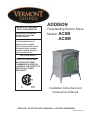
INSTALLER / CONSUMER
SAFETY INFORMATION
PLEASE READ THIS MANUAL
BEFORE INSTALLING AND
USING APPLIANCE
WARNING!
IF THE INFORMATION IN THIS
MANUAL IS NOT FOLLOWED
EXACTLY, AN ELECTRICAL SHOCK
OR FIRE MAY RESULT CAUSING
PROPERTY DAMAGE, PERSONAL
INJURY OR LOSS OF LIFE.
ADDISON
Freestanding Electric Stove
Models:
ACSB
ACSM
FOR YOUR SAFETY
DO NOT STORE OR USE
GASOLINE OR OTHER
FLAMMABLE VAPORS OR
LIQUIDS IN THE VICINITY OF
THIS OR ANY OTHER
APPLIANCE.
C
US
Installation Instructions and
Homeowner’s Manual
INSTALLER: DO NOT DISCARD THIS MANUAL - LEAVE FOR HOMEOWNER
30002351 7/06 Rev. 5
Addison Electric Stove
Table of Contents
PLEASE READ THE INSTALLATION & OPERATING INSTRUCTIONS
BEFORE USING THIS APPLIANCE.
Thank you and congratulations on your purchase of a Vermont Castings electric stove.
IMPORTANT: Read all instructions and warnings carefully before starting installation. Failure to follow these
instructions may result in a possible electric shock, fire hazard and will void the warranty.
Installation Instructions
General ............................................................................................................................... 3
Locating Your Stove ............................................................................................................ 3
Stove Dimensions ............................................................................................................... 4
Clearance to Combustibles ................................................................................................. 5
Hearth ............................................................................................................................... 5
Electrical Specifications....................................................................................................... 5
Electrical Connections ......................................................................................................... 6
Service Instructions
Firebox Removal ................................................................................................................. 6
Glass Information ................................................................................................................ 6
Replacing Light Bulbs.......................................................................................................... 6
Maintenance of Motors ........................................................................................................ 6
Electrical Wiring Diagram .................................................................................................... 7
Operating Instructions
On/Off Switch ...................................................................................................................... 7
Heater Control ..................................................................................................................... 7
Replacement Parts ....................................................................................................................... 8
Door Glass Replacement Parts and Installation.................................................................. 9
2
30002351
Addison Electric Stove
Installation Instructions
General
1. Read all instructions before using this appliance.
2. This appliance is hot when in use. To avoid
burns, do not let bare skin touch hot surfaces. If
provided, use handles when moving this appliance.
Keep combustible materials, such as furniture,
pillows, bedding, papers, clothes, and curtains at
least 3’ (1m) from the front of this appliance.
3. CAUTION: Extreme caution is necessary when
any heater is used by or near children or invalids and whenever the heater is left operating
unattended.
4. If possible, always unplug this appliance when not
in use.
5. Do not operate any heater with a damaged cord or
plug or after the appliance malfunctions, has been
dropped or damaged in any manner.
6. Any repairs to this stove should be carried out by a
qualified service person.
7. Under no circumstances should this stove be modified. Parts having to be removed for servicing must
be replaced prior to operating this stove again.
8. Do not use outdoors.
9. This heater is not intended for use in bathrooms,
laundry areas and similar indoor locations. Never
locate this appliance where it may fall into a bathtub
or other water container.
10. Do not run cord under carpeting. Do not cover cord
with throw rugs, runners or the like. Arrange cord
away from traffic areas and where it will not be
tripped over.
11. To disconnect this appliance, turn controls to the off
position, then remove plug from outlet.
an electric shock, fire, or damage the appliance.
15. To prevent possible fire, do not block air intakes
or exhaust in any manner. Do not use on soft
surfaces, like a bed, where openings may become
blocked.
16. This appliance has hot and arcing or sparking parts
inside. Do not use it in areas where gasoline, paint,
or flammable liquids are used or stored. This stove
should not be used as a drying rack for clothing,
nor should Christmas stockings or decorations be
hung on or near it.
17. Use this appliance only as described in this
manual. Any other use not recommended by the
manufacturer may cause fire, electric shock, or
injury to persons.
18. Avoid the use of an extension cord because the
extension cord may overheat and cause a risk of
fire. However, if you have to use an extension cord,
the cord shall be No. 14 AWG minimum size and
rated not less than 1875 Watts. The extension cord
must be a three wire cord with grounding type plug
and cord connector. The extension cord shall not
be more than 20 feet in length.
19. SAVE THESE INSTRUCTIONS.
Locating Your Stove
Your new freestanding electric stove may be installed
virtually anywhere in your home. However, when
choosing a location for your new stove, ensure that the
general instructions are followed. Also, for best effect,
install the stove out of direct sunlight.
12. Connect to properly grounded outlets only.
13. This appliance, when installed must be electrically
grounded in accordance with local codes, with the
current CSA C22.1 Canadian Electrical codes or
for USA installations, follow local codes and the
National Electrical Code, ANSI/NFPA NO. 70.
14. Do not insert or allow foreign objects to enter any
ventilation or exhaust opening as this may cause
30002351
3
Addison Electric Stove
Stove Dimensions
E
A
F
C
B
D
4324
Fig. 1 Addison dimensions.
4
A
Width of Stove Top
565 mm
22¹⁄₄”
B
Width at Legs
600 mm
23³⁄₈”
C
Depth at Legs
390 mm
15³⁄₈”
D
Depth at Apron
430 mm
17”
E
Depth at Stove Top
400 mm
15³⁄₄”
F
Total Height
635 mm
25”
30002351
Addison Electric Stove
Clearance to Combustibles
Electrical Connection
Back .............................................................. 0” (0 mm)
Sides ............................................................. 0” (0 mm)
Floor .............................................................. 0” (0 mm)
Top ........................................................... 12” (305 mm)
A 15 AMP, 120 Volt, 60 Hz circuit with a properly
grounded outlet is required. Preferably, the stove will be
on a dedicated circuit as other appliances on the same
circuit may cause the circuit breaker to trip or the fuse
to blow when the heater is in operation.
The unit comes standard with a 6’ (1828 mm) long
three wire cord, exiting from the rear of the stove. Plan
the installation to avoid the use of an extension cord. If
an extension cord must be used, it must be a minumum
14AWG, three wire with grounding type plug connector and rated not less than 1875 Watts. The extension
cord shall not be more than 20 feet in length.
Hearth
A hearth is not mandatory but it is recommended for
aesthetic purposes. We recommend a noncombustible
hearth which does not obstruct heater openings.
Electrical Specifications
Voltage .......................................120VAC/60Hz
Total Amps .................................12.20 Amps
Total Watts .................................1460 Watts
Heater Ratings ...........................1300 Watts
WARNING: Electrical outlet wiring must
comply with local building codes and
other applicable regulations to reduce the
risk of fire, electrical shock and injury to
persons.
WARNING: Do not use this stove if any
part of it has been under water. Immediately call a qualified service technician to
inspect the stove and replace any part of
the electrical system.
Installation of Logs
1. Turn off power to the unit.
2. Follow the directions for removing the firebox. Refer
to Page 6, Steps 1 through 7.
LG369
Fig. 2 Addison logset.
LG369
Addison logs
11/04
30002351
5
Addison Electric Stove
Service Instructions
WARNING: Disconnect power before attempting any maintenance or cleaning to
reduce the risk of fire, electrical shock or
personal injury
Firebox Removal
1. Unplug the electrical supply to the unit.
2. Let the stove cool if it has been operating.
Replacing Light Bulbs
This stove uses two clear 120 Volt, 40 Watt, E-12
socket base light bulbs (small base, chandelier candle
type). The 40 Watt bulbs are located under the log
set/ember bed. For convenience, if one of the bulbs
burns out, it may be a good idea to replace both of the
light bulbs.
1. Turn off power to the unit by unplugging the power
cord.
3. Move the stove away from wall to gain access
to the rear of the unit.
2. Let stove cool if it has been operating.
4. Locate the firebox mounting brackets on the rear of
the firebox. Remove the screws securing brackets.
(Fig. 3)
5. Remove firebox by sliding it rearward out of the casing.
6. Gently place firebox on its back on the floor.
7. To reinstall firebox, follow the above procedure in
reverse.
3. Remove the access plate on the back of the stove
by removing the screws. You should have a clear
view of the light bulbs. Put your hand over the
silver flame generator to remove or replace the light
bulb(s).
CAUTION: Be careful not to touch or bend the flame
generator.
4. Examine the bulbs to determine which bulb(s) need
to be replaced.
5. Unscrew defective bulb(s).
6. Install new 40 Watt light bulb(s).
7. Replace access plate. Plug power cord into wall
outlet.
Mounting
Bracket
WARNING: Do not exceed 40 watts per
bulb. Use of higher rated bulbs may result
in a fire, causing property damage or personal injury.
Maintenance of Motors
ST824
Fig. 3 Rear view of the stove showing the firebox mounting
bracket.
Glass Information
1.
2.
3.
ST824
Under no circumstances
should this product be
Addison
operated with missing or broken glass.
rear mounting bracket
Do not strike or slam the glass.
Do not use abrasive7/04
cleaners to clean the glass.
The motors used on the fan and the flame generator
assembly are prelubricated for extended bearing life
and require no further lubrication. However, periodic
cleaning/vacuuming of the fan/heater unit is recommended.
WARNING: Make sure the power is turned
off before proceeding.
4. This product uses tempered glass. Replacement
glass (with gasket) is available from the manufacturer and replacement should be carried out by a
qualified service person.
6
30002351
Addison Electric Stove
Electrical Wiring Diagram
Any electrical repairs or rewiring of this unit should be carried out by a licensed electrician in accordance with national
and local codes.
If repairing or replacing any electricial component or wiring, the original wire routing, color coding
and securing locations must be followed.
BLACK WIRE # 10
BLACK WIRE
N IN
CK
W
WHITE WIRE
BL
A
BLACK WIRE
REMOTE RECEIVER
IRE
#1
L OUT
WHITE WIRE #5
BLACK WIRE
#8
N OUT
BLACK WIRE
MOTOR
FLAME
GENERATOR
1
BLACK WIRE
RED WIRE LINE
WHITE WIRE WIRE
RED WIRE #1
BLACK WIRE
BLACK WIRE #7
SWITCH OFF/ON
BLACK WIRE #9
THERMOSTAT
BLACK WIRE # 6
L IN
WHITE WIRE #4
WHITE WIRE #2
WHITE WIRE #3
GREEN WIRE
WHITE WIRE
WHITE WIRE #12
HEATER
MOTOR
BLACK
HEATER
RED WIRE #13
ST828
Operating Instructions
Main On/Off Switch
The On/Off switch supplies power to
all of the functions of the stove. It is
located on the back of the unit.
NOTE: The On/Off switch must be
in the ON position when using the
remote control.
WARNING: During any service of
this appliance, the power to the
unit must be turned off. It is not acceptable to use the “On/Off” switch
to meet this requirement.
Heater Control
ST828
Addison wiring
rev 1 En
9/04
ON/OFF
Switch
Temperature
Control
HS101
Fig. 4 Control locations at the top rear
corner of the stove. HS101
30002351
Heater Control
5/02
The Heater Control acts to turn the
heater on and off as well as setting
the comfort level in the room. Turning the knob clockwise from the off
position will place the heater into
operation. The further the knob is
rotated clockwise, the higher the set
point temperature. Turning the knob
counterclockwise will lower the set
point temperature. Turning it all the
way counterclockwise will turn the
heater function off.
7
Addison Electric Stove
15
7
5
16
4
13
13
2
6
11
1
12
14
3
17
ON
OFF
9
CFM Corporation reserves the right to make changes in design, materials, specifications, prices and discontinue colors and products at any time,
without notice.
2351
Addison
parts 2
7/04
Addison Freestanding Electric Stove
2351
Models ACSB (2905), ACSM
(2907)
Ref.
1.
2.
3.
4.
5.
6.
7.
8.
9.
10.
11.
12.
13.
14.
15.
16.
17.
8
Addison electric
Description
parts
Log Set Complete
7/04
Fan/Heater Assembly
Flame Generator Motor-120 Volt AC w/Terminal
Cord Power 16/3 HPN w/Terminals
ON/OFF Switch
Heater Control (Thermostat)
Heater Control Knob
Door Glass, with gasket (not shown)
Flame Generator Assembly
Shield, Flame Generator
Light Bulb Socket w/Wiring Assembly
Front - Addison
End, Right/Left - Addison
Leg - Addison (2 per stove)
Top - Addison
Mounting Bracket
ON/OFF 120V 15Amp Integral Remote Control
Part Number
S31355
10006404
10004262
10003095
S14034
10004199
10001639
0003442
10007069
S10037
10003568
See Chart Page 9
See Chart Page 9
See Chart Page 9
See Chart Page 9
S32767
10006891
30002351
Addison Electric Stove
Door Glass Replacement Instructions
1. Unplug the electrical supply to the unit.
Door Glass Replacement Parts
Door Glass w/Gasket
0003442
Clip
1601396
Knob, Therm-Maple
1600660
Control Door Handle Assy
10004442
2. Allow the stove to cool if it has been operating.
3. Move the stove away from the wall to gain access to
the rear of the unit.
4. Locate the firebox mounting bracket on the rear of
the firebox. Remove the screws securing the firebox
to the mounting bracket. (Fig. 3)
5. Remove firebox by sliding it rearward out of the casting.
6. Gently place firebox on its back on the floor.
Glass
7. Locate the glass clips on the inside surface of the
front casting. Remove the glass, and clear the area
of any glass fragments. (Fig. 5)
8. Secure new glass (with gasket) to the inside surface
of the front casting, reversing the process above,
making sure the glass is placed with gasket covering
the bottom and sides of the glass. (Fig. 5)
9. Reinstall firebox into casting, by reversing steps 1
through 6.
Glass
Clips
Gasket
Fig. 5 Door assembly.
Shell Enamel Part Numbers - Addison ACSB, ACSM
Color
Top
Front
End,
Right, Left
Classic
30000624
30000621
30000622
Ebony
30000790
30000787
30000788
30002351
HS107
HS107
Addison
glass replace
5/02
Leg
(2 per stove)
30000623
30000789
9
Addison Electric Stove
10
30002351
1 YEAR WARRANTY
Addison Electric Stove
For Vermont Castings Electric Stove
BASIC WARRANTY:
CFM Corporation (hereinafter referred to collectively as
the “Company”) warrants that your new electric stove is
free from manufacturing and material defects for a period
of one year from date of installation, subject to the following conditions and limitations.
1. This electric stove must be installed and operated at all
times in accordance with the Installation and Operating instructions furnished with the product. Any alteration, willful
abuse, accident, or misuse of the product shall nullify this
warranty.
2. This warranty is non-transferrable, and is made to the
original owner, provided that the purchase was made
through an authorized supplier of the Company.
3. This warranty is limited to the repair or replacement of
part(s) found to be defective in material or workmanship,
provided that such part(s) have been subjected to normal
conditions of use and service, after said defect is confirmed by the Company’s inspection.
4. This warranty does not cover the lightbulb(s) included
with the stove.
5. The Company may, at its discretion, fully discharge all
obligations with respect to this warranty by refunding the
wholesale price of the defective part(s).
6. Any installation, labour, construction, transportation, or
other related costs/expenses arising from defective part(s),
repair, replacement, or otherwise of same, will not be
covered by this warranty, nor shall the Company assume
responsibility for same. Further, the Company will not be
responsible for any incidental, indirect, or consequential
damages, except as provided by law.
30002351
7. All other warranties - expressed or implied - with respect
to the product, its components and accessories, or any obligations/liabilities on the part of the Company are hereby
expressly excluded.
8. The Company neither assumes, nor authorizes any third
party to assume, on its behalf, any other liabilities with
respect to the sale of this Vermont Castings product.
9. The warranties as outlined within this document do not apply to non-CFM Corporation accessories used in conjunction with the installation of this product.
This warranty is void if:
a) The stove has been operated in atmospheres contaminated by chlorine, fluorine or other damaging chemicals.
b) The stove is subjected to prolonged periods of dampness or condensation.
c) Any alteration, willful abuse, accident, or misuse of the
product.
IF WARRANTY SERVICE IS NEEDED . . .
1) Contact your supplier. Make sure you have your warranty,
your sales receipt, and the model/serial number of your
CFM Corporation product.
2) DO NOT ATTEMPT TO DO ANY SERVICE WORK
YOURSELF.
11
CFM Corporation
2695 Meadowvale Blvd. • Mississauga, Ontario, Canada L5N 8A3
800-668-5323 • www.cfmcorp.com