1
T-FLEX Parametric CAD
B RIEF I NTRODUCTORY C OURSE
«Top Systems»
Moscow, 2014
©Copyright 2014 Top Systems
This Software and Related Documentation are proprietary to Top Systems. Any copying of this
documentation, except as permitted in the applicable license agreement, is expressly
prohibited.
The information contained in this document is subject to change without notice and should not
be construed as a commitment by Top Systems who assume no responsibility for any errors or
omissions that may appear in this documentation.
Trademarks:
T-FLEX Parametric CAD, T-FLEX Parametric Pro, T-FLEX CAD, T-FLEX CAD 3D are
trademarks of Top Systems.
Parasolid is a trademark of Siemens PLM Software.
All other trademarks are the property of their respective owners.
Table of Contents
TA BL E O F C O N T EN T S
Table of Contents ................................................................................................. 3
Features and Area of Application ........................................................................ 7
Conventions Adopted in the T-FLEX CAD Guidelines ......................................... 9
Getting Started ................................................................................................... 13
System Requirements ......................................................................................................... 13
Hardware Requirements ..................................................................................................................13
Software Requirements ....................................................................................................................14
T-FLEX CAD System Setup................................................................................................. 14
Installing Hardware Protection Key ...............................................................................................14
Installing Network Hardware Protection Key ...............................................................................14
Installing Software and Hardware Protection Key .......................................................................14
What is Going on in Setup? .............................................................................................................15
The T-FLEX CAD Main Window Layout .....................................................................................15
Service Windows and Elements of Control of T-FLEX CAD ......................................................17
Working with Tool Windows...........................................................................................................19
Drawing Basic Terms .......................................................................................................... 23
Construction Entities ........................................................................................................................24
Graphic Entities ................................................................................................................................25
Auxiliary Elements ...........................................................................................................................28
Drawing Techniques............................................................................................................ 28
Creating Parametric Drawing in T-FLEX CAD ...........................................................................29
Creating Non-Parametric Drawing (Sketch) in T-FLEX CAD....................................................30
Fast Drawing Creation. Automatic Parametrics ...........................................................................30
Quick Reference on User Interface .................................................................................... 30
Getting Help ......................................................................................................................................30
Mouse Interface. Context Menu ......................................................................................................30
Calling a Command ..........................................................................................................................32
Canceling a Command .....................................................................................................................35
Starting System, Saving Drawing, Exiting System ........................................................................35
Function Keys ...................................................................................................................................37
Brief Introductory Course .................................................................................. 39
Creating Parametric Drawing ............................................................................................. 39
Creating Sketch, Non-parametric Drawing ........................................................................ 53
Creating a parametric drawing in the automatic parameterization mode....................... 62
Main Concepts of System Operation ................................................................. 73
Document Management ...................................................................................................... 73
Creating New Document ..................................................................................................................73
Opening Document ...........................................................................................................................74
3
Fundamentals. Two-dimensional design
Panning and Zooming in Active Drawing Window ...................................................................... 74
Status Bar.......................................................................................................................................... 76
Toolbars ............................................................................................................................................ 77
Bird’s Eye View Window ................................................................................................................ 81
Using Model Menu ........................................................................................................................... 82
Rulers ................................................................................................................................................ 82
Property Window ............................................................................................................................. 83
Automenu .......................................................................................................................................... 84
Dynamic Toolbar.............................................................................................................................. 84
Active Drawing Window ...................................................................................................... 86
Document tabs .................................................................................................................................. 86
Document Window View with Turned on/off Document Tabs ................................................... 87
Selection of active window............................................................................................................... 88
Drawing Window Scrollbars ........................................................................................................... 89
Arranging document windows with turned on document tabs.................................................... 90
Arranging Document Windows with Turned off Tabs................................................................. 92
Additional window of document ..................................................................................................... 94
Splitting Drawing Window.............................................................................................................. 96
Closing document window............................................................................................................... 99
Flagged Commands.......................................................................................................................... 99
Managing Multi-Page Documents .................................................................................................. 99
Information Window........................................................................................................... 100
Creating and Editing Drawing Elements .......................................................................... 101
Snapping Mode. Snap Types ......................................................................................................... 101
Using Grid ....................................................................................................................................... 106
General Concepts of Element Creation ....................................................................................... 107
General Concepts of Editing Elements ........................................................................................ 109
Copying element properties through clipboard .......................................................................... 114
Limiting Element Selection. Using Selector and Filter ............................................................... 114
Element Search ............................................................................................................................... 118
Moving, Copying, Transforming Elements. Working with Clipboard ..................................... 119
Undoing User Actions .................................................................................................................... 120
General Principles of Assigning Parameters. Assigning Variables to Parameters .................. 121
Setting Common Parameters of System Elements ......................................................... 123
Color ................................................................................................................................................ 124
Layer ............................................................................................................................................... 124
Level ................................................................................................................................................ 125
Priority ............................................................................................................................................ 128
Controlling Element Visibility ........................................................................................... 128
Diagnostics window........................................................................................................... 130
Checking spelling for drawing .......................................................................................... 133
Customizing System ........................................................................................ 135
Setting Options. Dialog of “Set System Options” Command ........................................ 135
“User Info” Tab.............................................................................................................................. 135
“Preferences” Tab .......................................................................................................................... 136
“Files” Tab ...................................................................................................................................... 138
“Save” Tab ...................................................................................................................................... 139
“Colors” Tab .................................................................................................................................. 139
4
Table of Contents
“Fragments” Tab ............................................................................................................................140
“Snap” Tab......................................................................................................................................141
“Windows” Tab ..............................................................................................................................142
“Folders” Tab .................................................................................................................................143
“BOM” Tab .....................................................................................................................................144
“3D” Tab .........................................................................................................................................144
«T-FLEX DOCs» Tab ....................................................................................................................148
Customizing Toolbars and Keyboard .............................................................................. 148
Controlling Toolbar Visibility .......................................................................................................149
“Toolbars” Tab ...............................................................................................................................150
“Commands” Tab ...........................................................................................................................151
“Keyboard” Tab .............................................................................................................................151
“Main toolbar” tab .........................................................................................................................152
“Environment” Tab ........................................................................................................................154
“Options” tab ..................................................................................................................................155
“3D Input Device” Tab...................................................................................................................156
Saving User Settings. Environments ............................................................................... 157
Adding user's commands ................................................................................................. 159
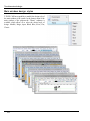
Main window design styles............................................................................................... 162
Customizing Drawing ....................................................................................... 163
Customizing Drawing. Dialog of “Set Model Status” Command ................................... 163
“General” Tab.................................................................................................................................164
“Font” Tab ......................................................................................................................................166
“Dimensions” Tab...........................................................................................................................167
“Alternative Dimensions” Tab ......................................................................................................169
“Lines” Tab .....................................................................................................................................170
“Preferences” Tab ..........................................................................................................................172
“Colors” Tab ...................................................................................................................................175
“Screen” Tab ...................................................................................................................................176
“Preview” Tab.................................................................................................................................178
“Symbols” Tab ................................................................................................................................179
“3D” Tab .........................................................................................................................................180
Default Parameters ............................................................................................................ 183
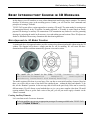
Basic 3D Terms and Concepts of Modeling with T-FLEX CAD ....................... 185
Introduction to 3D Modeling ............................................................................................. 185
Basic Topology Elements ...............................................................................................................185
Basic Geometrical Terms in T-FLEX CAD .................................................................................186
3D Entities and Operations ............................................................................................... 186
3D Construction Entities ................................................................................................................187
Basic Three-Dimensional Operations ...........................................................................................190
Sheet Metal Operations ..................................................................................................................193
Face Handling Operations .............................................................................................................195
Copy and Insert Operations for 3D Elements..............................................................................197
Operations for Creating 3D Arrays ..............................................................................................198
Deformation Operations ................................................................................................................199
Commands to Create Welds ..........................................................................................................201
Geometry Analysis Commands .....................................................................................................202
5
Fundamentals. Two-dimensional design
Engineering Analysis ..................................................................................................................... 204
Auxiliary Elements and Operations ............................................................................................. 206
2D Projection .................................................................................................................................. 207
3D Annotation ................................................................................................................................ 207
3D Object Rendering ..................................................................................................................... 208
Three-Dimensional Model Animation .......................................................................................... 210
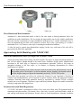
Approaching Solid Modeling with T-FLEX CAD .............................................................. 210
General Recommendations before You Begin with 3D Model Creation .................................. 210
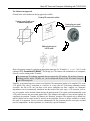
Parameterization and Model Regeneration ................................................................................. 210
Three-Dimensional Model Creation Techniques ........................................................................ 212
3D Model Rollback Mode .............................................................................................................. 217
T-FLEX CAD System Operation Tips ................................................................................ 220
Getting Help.................................................................................................................................... 220
Creating a New Document. Using Prototype Templates ............................................................ 220
Mouse Interface. Context Menu ................................................................................................... 221
Calling Commands from Keyboard, Using an Icon, from Textual Menu ................................ 223
Setting up Parameters of a New Element .................................................................................... 225
Preview ............................................................................................................................................ 227
Editing Parameters of Operations with the Help of Draggers Outside of Commands ........... 227
Draggers of External Variables .................................................................................................... 228
Preview of Operation Result ......................................................................................................... 228
The Groups of T-FLEX CAD 3D Modeling Commands ............................................................ 229
Customizing List of Element Types for Selection ....................................................................... 237
Element Selection ........................................................................................................................... 237
Element Search ............................................................................................................................... 239
Opening New Windows ................................................................................................................. 240
Manipulating Model in 3D Window ............................................................................................. 241
“Model” Window ........................................................................................................................... 241
“Diagnostics” Window................................................................................................................... 249
Arranging Tool Windows .............................................................................................................. 251
Toolbars .......................................................................................................................................... 251
Customization ................................................................................................................................. 252
Brief Introductory Course in 3D Modeling ...................................................... 253
Main Approach to 3D Model Creation .............................................................................. 253
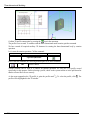
Creating Auxiliary Elements......................................................................................................... 253
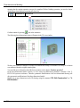
Creating Rotation Operation ........................................................................................................ 258
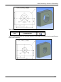
Creating Holes ................................................................................................................................ 258
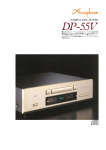
Creating a Blend............................................................................................................................. 267
Creating a Drawing........................................................................................................................ 268
“From Drawing to 3D Model” Approach .......................................................................... 273
6
Introduction
F E ATU R ES AN D A R EA O F A P PL I CATIO N
T-FLEX CAD is a parametric design and drawing system. T-FLEX provides high levels of drawing
flexibility and supports modifications of the drawings while maintaining constraints imposed by the designer
on the drawing elements. The unique parametric engine and a complete set of professional tools for
computer-aided design simplify the design workflow and speed up preparation of drawing materials. TFLEX CAD gives a designer a familiar feel of working with traditional paper and ruler equipment.
Associative design driven by assigning and modifying variable parameters is the way to follow by all design
and drawing automation systems. The particular success of T-FLEX CAD is based, in the first place, on the
new paradigm of geometric modeling. This paradigm is about a new, deeper, level of parameterization,
compared to other systems. The idea of parameterization itself has nowadays become a standard in CAD. By
“parameterization” we usually mean a provision for a drawing extensive reuse by means of modifying its
parameters. Virtually all CAD vendors claim parametric capabilities of their systems. However, these
systems, originally introduced long before parameterization was adopted, often use their legacy data
structures that are inherently non-parametric. This causes their solutions to suffer from ineffectiveness or
limited range of applicability. The T-FLEX CAD’s revolutionary approach to the idea of parameterization
and the fact that the drawings are based on inherently parametric models provide a new dimension for
parametric design.
T-FLEX CAD uses concepts and practices that are familiar to designers. At the same time, the user does not
need to care about making a precise drawing at once. The modification capabilities via both dimensioning
and free dragging are unmatched across other CAD systems.
The assembly drawing environment is unique in its wide range of capabilities. T-FLEX CAD permits
creating complex drawings where certain fragments can be bound by relations. A relation can be established
either via geometrical properties or by parameters. The system correctly handles lines visibility throughout
modifications, if some portions of the drawing overlap the others, with no limitation on the number of
overlaps. It takes seconds to create drawings of a new product in a family by varying assembly drawing
parameters. The modifications instantly reflect not only on the assembly but also on the member fragments
(parts) and all the rest of the related documentation.
One typical attribute of the parametric CAD systems is a language for programming parametrical relations.
T-FLEX CAD has another advantage in this area. The engineer is not required to have any training in
programming. The drawing parameters can be represented by variables. These variables can be related in
simple mathematical expressions. This is done without using any programming language. The variables can
be assigned either at creation of an element or while editing an existing one. The values of the variables can
be obtained from other drawings or automatically input from a database. This provides for unlimited
modification capabilities in drawing.
Along with parametric design, T-FLEX CAD supports wide usage of quick drawing producing nonparametric sketches. This approach allows creating drawings in a way similar to major CAD systems by
using a standard set of tools for drawing, i.e. various primitives, as arcs, circles, line segments, etc. The
snapping mechanism is provided for easy sketching of new entities, such as horizontal and vertical alignment
of the cursor with the existing entities or their ends, center-of-arc and center-of-circle snapping, etc. When
creating arcs, snapping occurs around the 90, 180 and 270 degrees. The cursor also snaps to horizontal and
7
Two-Dimensional Design
vertical alignments with the arc center. The system automatically identifies multiple pairs of same-object
snappings. Snapping to any object can be locked with the Function key, and the cursor will follow to the
locked snapping condition. Thus, the sketcher provides a way of quick drawing, however, such drawings do
not take full advantage of parametric dimension modifications. Therefore, this method is only recommended
when no substantial modifications are expected on the drawing.
Creation of parametric construction-based drawings can be accelerated with the special parametric sketch
mode. This mode combines efficiency of non-parametric drafting with flexibility of parametric construction.
This goal is achieved by simultaneous actions of a user and the application: user creates his drawings using
ordinary sketch features, and application “puts” geometrically related construction elements under the sketch
lines thus producing a parametric drawing.
The highly effective functionalities of T-FLEX CAD make the system usable in a wide range of situations.
The system can well be used in mechanical design, such as design of industrial equipment and tooling,
development of molds and stamps, design of consumer goods, etc. It also supports development of
manufacturing process flow charts and BOM, numerically controlled machining and other technological
procedures. Other possible application fields include construction and architectural design, charting various
types of graphs, dynamical visualization of processes and mechanisms, industrial and graphic design. The
most effective uses of T-FLEX CAD occur when the parametric design paradigm dominates the design
process, and when all stages of design are involved, from sketch to scratch drawing to production drawing.
T-FLEX CAD facilitates considerable speed-up of graphic design and documentation cycle.
T-FLEX CAD offers a complete range of drawing tools, such as creating various-type line drawings,
hatches, dimensions, text, roughnesses, special symbols, etc. Important that all these design attributes can be
associated with the parameters of the drawing. This means, modifying a drawing parameter would cause
adjustment of the design attributes. The drawings follow the user-specified international standard. T-FLEX
CAD also supports instant switching from one drawing standard to another.
The three-dimensional version CAD 3D is intended for making parametric 3D models. The 3D solid bodies
authored by the system can easily be modified. Parametric modifications of the 2D drawings propagate on
the model's 3D representation, and vise versa.
T-FLEX CAD can be used as a base for developing specialized CAD systems. The system supports
exporting parametric drawing data to custom processing modules. Vise versa, externally generated parameter
values can be imported into the system and assigned to the drawing parameter variables. The model is then
automatically regenerated, and the new design drawing is ready.
The system software utilizes the latest GUI standards. Even a novice user can easily start working with the
system. The menu and icon layout is easy to use. The command dialog boxes are intuitive. The various
drawing elements and the libraries of drawings allow effortless manipulation. The built-in contextdependent Help facilitates quick learning. Every command is realized in a way that provides users –
engineers and designers - with confidence in operating the system.
The theory and algorithms used in the system are unique yet unambiguous to end-users.
8
Introduction
C O N V EN TIO N S A D O P T ED IN TH E T-FLEX CAD
G U I DE L IN E S
The following standard conventions are adopted in this document:
<Enter>, <L>, <Esc>, etc. – notations for the keys on the computer keyboard.
[OK], [View], etc. – notations for graphic buttons in the dialog boxes.
- Left mouse button click.
- Right mouse button click.
- Left mouse button double-click.
,
,
, etc. – icons on a toolbar or on an icon automenu.
“File|Open…” etc. – selection of a textual menu bar item
“File”, followed by a pull-down menu item “Open…”.
“Font|Name” etc. – selection of a tab “Font” in a dialog box
followed by an item “Name”, or selection of a group of
parameters in a dialog box followed by a particular parameter.
9
Two-Dimensional Design
“O: Open Model”, “EL: Construct Ellipse”, etc. – names of T-FLEX CAD commands. Note that the
character combinations before the colon define the keystroke accelerator sequences for invoking commands
by typing in the status bar.
A command can be invoked in T-FLEX CAD by the following three ways:
By typing,
By selecting the toolbar item, and
By selecting the textual menu item.
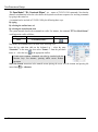
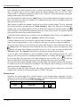
The system manuals describe the commands in a table. For instance, the command “ST: Set Model Status”
would appear in a table as follows,
Keyboard input
Textual menu
<ST>
“Customize|Status…”
Icon
This means, the command can be invoked in the following ways:
Press the key <S> then <T> on the keyboard, or – select the entry
“Customize” in the menu bar, then select “Status…” from the pull-down
in the appropriate toolbar.
menu, or – select the icon
Certain most common commands can also be invoked with the
function keys. For instance, pressing <F7> causes Redraw
operation.
Select an element instruction in the manuals means placing the cursor over the element and pressing left
mouse button or <Enter>.
10
Introduction
Select an icon, press an icon, select an input box, press a button
instruction means placing the cursor over the item (icon, input box,
dialog box button) and pressing left mouse button .
Point at an element, point at an icon, point at a button means
just placing the cursor over the item.
Each command usually brings a list of options available under this
command. An option is one specific action performed within the
command, as delete an element, select an element of a particular
type, switch to another mode, etc.
Each option is represented by a button and an icon in the
automenu.
Invoking an option via the keystroke mechanism might be different
than by selecting the icon. Typing the keystroke sequence instantly
invokes the action, while selecting an icon may work in two ways.
First possibility is – an instant action occurs, as, for instance, when
specifying parameters of an element via
.
Second – after selecting the icon, the system waits for a specific user action, with the
cursor being modified with a glyph corresponding to the action. The action completes
when the cursor is pointed at an appropriate element and left mouse button
.
pressed. For instance, this can be a selection of a construction line –
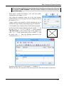
The command description contains various ways of creating elements. For instance, the following sequence
describes creation of a construction circle:
The command description contains various ways of creating elements. For instance,
the following sequence describes creation of a construction circle:
<L>, <L>, <L> - a circle tangent to three lines.
The above sequence uses a typical notation which implies that the respective
automenu icon picks can be used instead of the keystrokes, for instance,
<L>,
,
, <L> is a way of creating a three-line-tangent circle using both the keystrokes and the icon.
,
is a way of creating a three-line-tangent circle via the automenu icon picks.
, <L>, <L>, etc. – other possible combinations.
In the system description, “Press ” usually means that either left mouse button or <Enter> key can be
pressed. The <Enter> key works as a left mouse click while working within the
command dialog box.
11
Two-Dimensional Design
In the system description, “Press
” means that either right mouse button
or <Esc> key can be pressed.
also holds when working in the drawing area of the application. Use of
in other
This convention about
areas of the screen follows the standard conventions of Windows (usually, this invokes the context-sensitive
menu).
12
Getting Started
G E T TIN G S TA RTE D
This chapter contains sections helpful in getting started with the system setup and basic operation: “System
Requirements”, “T-FLEX CAD System Setup”, “Basic Terms and Drawing Techniques”, “Quick Reference
on User Interface”.
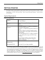
System Requirements
Hardware Requirements
Computer:
Processor:
Videocard:
PC with USB port
Pentium IV or compatible with support of instructions
SSE2
Intel Core i7
Videocard with OpenGL 3.3 support is recommended for
efficient work with assemblies.
OpenGL 4.2 – for improved visualization of models in 3D
scene.
OpenGL 1.0 allows to work with 3D models, but with
restrictions (threads, welds, graphic sections and textures
will not display).
Videocard supporting CUDA 2.3 or higher is required for
creation of photorealistic images with NVIDIA Optix
technology.
High-performance NVIDIA videocard with 1GB of
memory or higher and with Open GL 4.2 support or
higher is recommended.
*
Minimum RAM:
1G
Recommended RAM:
4G or more* (for very large assemblies)
32-bit operating systems Microsoft Windows have a limitation of 4GB of memory address space. This 4GB
space is evenly divided into two parts, with 2GB dedicated for kernel usage, and 2GB left for application
usage. Each application (including T-FLEX CAD) gets its own 2GB, but all applications have to share the
same 2GB kernel space. For Windows XP and Windows Vista it is possible to increase the default
allocation capabilities up to 3GB (3GB for user mode, 1GB reserved for kernel). Such capability requires
additional tunings in order to be effective (see http://support.microsoft.com for more information).
13
Two-Dimensional Design
64-bit operating system Windows does not have limitations in terms of size of random access memory and
does not require any additional settings to control it. Up to 4GB of memory is automatically allocated for
32-bit applications (such as T-FLEX CAD).
To fully exploit the capabilities of 64-bit operating system, there is a special 64-bit version T-FLEX CAD
x64. Combination of T-FLEX CAD x64 with Windows x64 allows using unlimited amount of random
access memory in working with T-FLEX CAD.
Software Requirements
Operating system:
Windows XP/Vista/Windows 7/ Windows 8
T-FLEX CAD System Setup
Installing Hardware Protection Key
T-FLEX CAD is distributed with a hardware protection key (HASP). To run the system, connect the HASP
key to USB port of your PC.
The driver for the HASP key is installed automatically as part of the T-FLEX CAD installation process.
Shall any problems occur with this driver, it can be re-installed separately, with custom settings specified as
necessary. To do this, run haspdinst.exe from the name\PROGRAM\Hinstall folder, where name is
the installation folder of the T-FLEX CAD. To get detailed instructions of the program usage, run it with the
option /help.
Running haspdinst.exe requires administrator privileges.
The driver is not needed when using a network protection key.
Installing Network Hardware Protection Key
Network hardware protection key installation is performed by system administrator.
All necessary manuals and auxiliary programs for network hardware protection key installation are available
in LAN-UTIL 2006 folder.
Installing Software and Hardware Protection Key
Do not insert Hardware Protection Key into USB-port until T-FLEX CAD installation complete.
T-FLEX CAD installation with examples, libraries and auxiliary utilities is available on DVD.
Perform the following steps to install T-FLEX CAD on your PC:
1. Run Windows
2. Insert DVD-disk with T-FLEX CAD installation into DVD-drive.
3. Run Setup.exe file from T-FLEX Prerequisites 12 folder.
This installation should be performed one time even after T-FLEX CAD reinstalling or uninstalling.
4. Run T-FLEX CAD 12.msi from T-FLEX CAD 12 folder and follow installation wizard instructions.
You can install either T-FLEX CAD x32 or T-FLEX CAD 12 x64 running msi file from appropriate folder.
14
Getting Started
Installation wizard will install examples and standard parts automatically.
5. Run appropriate msi files to install tutorials and necessary add-ons.
Press [Cancel ] button to interrupt installation process.
After installation complete new folder will be created in Program Files directory on your PC.
What is Going on in Setup?
The T-FLEX CAD application files on the CD ROM are in a compressed format. The installer extracts and
copies these files into the specified folder on your PC’s hard disk. The memory and disk space are monitored
during the installation, and an error message is displayed if these are insufficient.
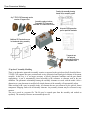
T-FLEX CAD is distributed with a set of sample drawings, and a library of standard elements. The installer
program creates appropriate subfolders under the installation home folder. The data structure of these
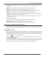
subfolders is as follows:
\T-FLEX
CAD 14\
Parametric
PROGRAM
Libraries
Documents
API
The T-FLEX CAD system files
The library element files
The system reference files
Examples on Open API and Application Wizard
usage for developing T-FLEX CAD add-on applications.
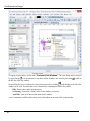
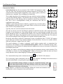
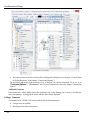
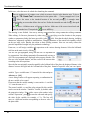
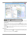
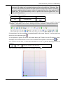
The T-FLEX CAD Main Window Layout
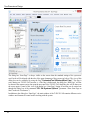
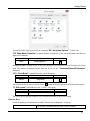
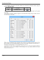
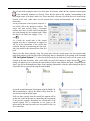
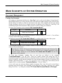
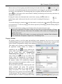
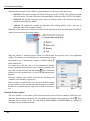
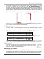
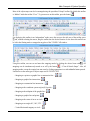
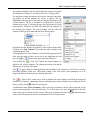
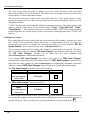
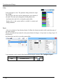
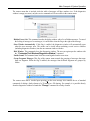
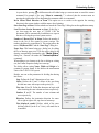
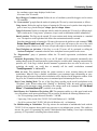
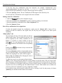
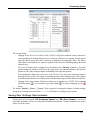
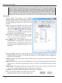
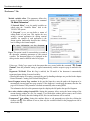
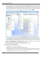
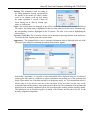
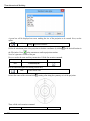
After installation the dialog box “Start Page” opens up in the T-FLEX CAD window. It includes several
sections. In the section “Recent Documents” a list of recently used documents is shown. To open any of
these documents, it is sufficient to point the cursor at any of them and press . The button [Open…] can
also be used. The section “New Document” allows creating a new document on the basis of any of the
existing templates. For convenience all templates are divided into groups (“Common”, “Forming Feature”,
“Bom”, “Ray Tracing”). The content of these sections duplicates the functionality of the menu
“File|Recent Files” and the command “FP: Create New Document Based on Prototype” (more
details on how to use these capabilities will be given in the chapter “Main Concepts of System Operation”).
The last chapter – “Welcome to T-FLEX CAD” – contains various useful links related to working with
T-FLEX CAD.
15
Two-Dimensional Design
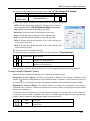
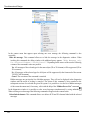
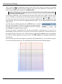
The dialog box “Start Page” is always visible on the screen when the standard settings of the system are
used. Its tab will be aligned with the tabs of the open documents of the system (see below). The view of this
dialog box can be controlled by using the flag “Customize|Tool Windows|Start Page”. This flag is
active during one T-FLEX CAD session, i.e. if the flag is disactivated, the dialog box “Start Page” will not
be shown in the current session, but upon the next start of the T-FLEX CAD the dialog box will be shown on
the screen again. Control of the view of the dialog box “Start Page” during all sessions can be carried out
through the dialog box of the command “SO: Set Systems Options” (parameter “Show Start Page on
Start” on the tab “Preferences”).
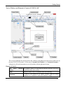
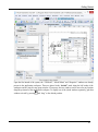
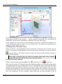
In addition to the dialog box “Start Page”, the main window of the T-FLEX CAD contains different service
windows and elements of control used in working with the system.
16
Getting Started
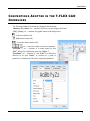
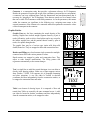
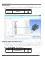
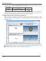
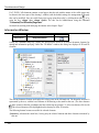
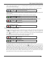
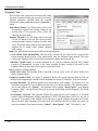
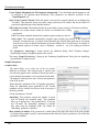
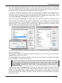
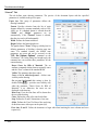
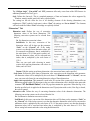
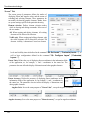
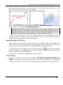
Service Windows and Elements of Control of T-FLEX CAD
The user can reconfigure the layout (position and visibility) of the dialog boxes and various control bars on
the main T-FLEX CAD window. Use the menu “Customize|Tool Windows” or “Customize|Customize…”.
Alternatively, click at the automenu or one of the toolbars with the right mouse button.
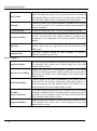
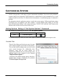
Elements of Control
The
active
window
drawing The graphics window for displaying the drawing. Drawings can only be
created and edited in this window.
Ruler
Indicates current X and Y coordinates in the active drawing.
Automenu
A menu of icon buttons for the options available within the current
command. If no command is current, the automenu is empty.
17
Two-Dimensional Design
Main Toolbar
Contain icon buttons for T-FLEX CAD commands. Besides the main
toolbar, the application window of the system can contain several toolbars
(including the toolbars created by the user). Toolbars can be docked along
one of the main window borders, or stand alone as floating windows.
Status bar
Contains the name of the current command, a prompt for the expected
user action, the current X and Y coordinates, and the command-dependent
auxiliary coordinate.
Textual Menu Bar
Contains the textual menu of the T-FLEX CAD commands by groups.
The System Toolbar
Contains the fields for modifying current settings of entities, such as color,
line type, level, and layer. Also contains controls for modifying layer
configuration, level configuration of the current document, and selector
settings.
Page Tabs
Provide quick access to the desired page in a multi-page document. To
activate a page, select the respective tab. Tabs are not shown for the
hidden pages.
Document Tabs
Help quick navigation through the open documents. To activate a
document, select the respective tab.
Service Windows
18
Properties Window
Is used for specifying parameters in transparent mode within most 2D and
3D commands. This window can be docked along one of the main
window borders, or float.
Bird’s Eye View Window
Displays the fitted view of the drawing, regardless of the current
pan/zoom in the drawing window. Helps to quickly pan to any portion of
the drawing. The window can be docked along one of the main window
borders, or float.
Model Menu Window
Contains graphical and textual representation of the libraries and the
drawings in the current library configuration. Helps quick loading of a
desired drawing and browsing drawing libraries. The window can be
docked along one of the main window borders, or float.
3D Model
(only for 3D release)
This window displays the structure of the 3D model, such as the existing
workplanes and other auxiliary 3D entities and their dependencies, and the
operations used for creating the model. The window can be docked along
one of the main window borders, or float.
Diagnostics Window
Displays messages about errors or failures that may occur during T-FLEX
CAD operation. The window can be docked along one of the main
window borders, or float.
Getting Started
Window “Variables”
An additional window of variables editor which enables to work with the
variables in an transparent mode, and simultaneously work with the
drawing window or 3D model window. Upon changing the value of the
variable, the model is regenerated transparently in the current window. All
changes are immediately reflected on the drawing. This window can be
docked along one of the main window borders, or float.
Macros Window
This window displays macros of the current document and macros from
T-FLEX installation folder “…\Program\ Macros”. The window
helps to start macros for execution.
Studies Window
(only for 3D release)
The window displays data of the current document FEA and Dynamics
studies. This window can be used for operations with studies.
Weld Window
This window contains lists of welds created in the current document.
Window “Materials”
Window for working with the materials of 3D model and also with the
material libraries of T-FLEX CAD.
Window
structure”
Displays the model’s structure. It allows us to add annotation elements to
the product’s structure, transforming it to the form of a single or group bill
of materials.
“Product’s
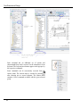
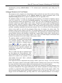
Working with Tool Windows
The system tool windows (the properties window, “3D model”, “Model Menu”, the Bird's eye view window,
“Macros”, the diagnostics window and other windows) can be positioned in the main application window in
various ways. Those can be “docked” at the side of the working window, made “hideable” or set to
“floating” mode. To save the workspace, some windows can be joined in one group window. Unused tool
window can be turned off.
19
Two-Dimensional Design
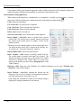
To engage a tool window, use the menu “Customize|Tool Windows”. The same dialog can be accessed
over an automenu of any other toolbar. Windows are closed by the button located on
by right clicking
the title bar of the tool window.
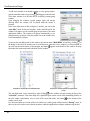
In controlling the service windows, the context menu accessed by clicking
on the heading or the tab of the
window can be used. The menu has several commands for controlling the state of the window:
− Hide. Remove the window from the screen;
− Set floating. Turn on the “floating” mode for the window (see below);
− Auto Hide. Turn on/off the auto hide mode for the window.
A set of commands available in the context menu is dependent on the state of the current window.
20
Getting Started
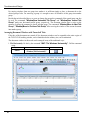
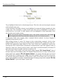
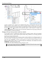
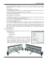
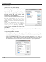
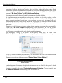
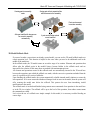
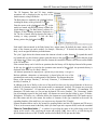
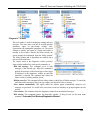
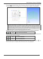
Upon the first launch of the system, the “3D Model”, “Model Menu” and “Properties” windows are already
present in the application workspace. Those are placed in the “docked” mode along the left border of the
workspace and are joined in one group window. If necessary, the two windows can be moved to any location
along the perimeter of the application workspace. To display one of the joined windows separately, grab that
window at its tab by pressing and “drag” to the desired position.
21
Two-Dimensional Design
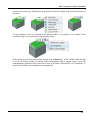
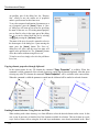
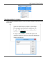
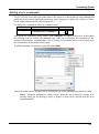
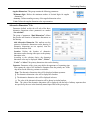
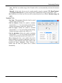
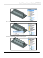
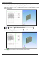
To add a tool window to an already existing or a new group window,
grab the intended window by pressing and dragged to the title area
of the other window or to the tabs area of an already existing group
window.
Upon dragging the windows several prompt signs will emerge
showing where the window will be placed when the mouse is
released.
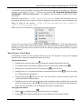
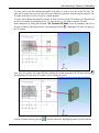
In the cases when most of the workspace is needed, you can set the
“auto hide” mode for the tool windows. In the auto hide mode, the
window will appear as a tab located along the perimeter of the main
application window. The window will appear automatically as you
point the mouse to this tab. Once the pointer leaves the window area,
it will automatically collapse.
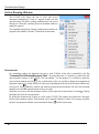
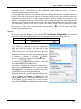
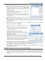
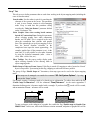
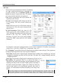
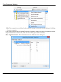
To turn on the auto hide mode for the window, the context menu “Auto Hide” accessed by clicking
on
the header or the tab of the window can be used. Moreover, when the service window is in fixed position on
one side from the main window of the program, the button appears on the header of the window. Pressing
this button also turns on the auto hide mode for the window.
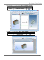
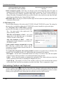
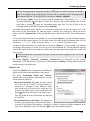
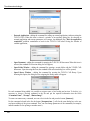
“Properties” window tab in the autohide mode
“Properties” window expands when pointed by
mouse
The auto hide mode can be canceled by right clicking
on the window tab and clearing the flag of the
“Auto hide” parameter. This mode helps save significant space on the screen while maintaining benefits of
the tool window functionality. Also, to turn off the auto hide mode, the button
on the header of the
window can be used.
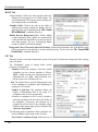
It is often convenient to set some of the tool windows or a whole group window into the “floating” mode. In
this way, the tool window can be placed anywhere within the application workspace without being docked.
22
Getting Started
Setting a tool window into the floating mode is done by grabbing the window title or tab in the group
window by pressing
and dragging into the drawing area of the application window. You can set to this
mode not only separate windows, but group windows as well. To do this, grab a group window at the title by
pressing
drag into the drawing area of the application
window in the same way.
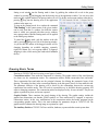
To turn on the floating mode for a window the command
“Set floating” in the context menu of the given window
can be used. Note that if a window, for which the context
menu is called, was grouped with other service windows
into a group window, then the floating mode will be applied
to the whole group window.
To cancel the floating mode, grab the window at the title
and by pressing drag it to a side of the drawing window.
As you do this, the outline of the dragged window will be
changing depending on available snapping: separately
(right, left, bottom, etc.) or in a group window. To suppress
snapping to sides, while moving the window hold <Ctrl>
the key.
Drawing Basic Terms
Drawing in T-FLEX CAD involves using several types of entities.
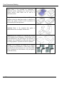
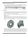
Construction entities. These make the framework of a drawing. The graphic entities of the actual drawing
are drawn over the construction entities. The construction entities include construction lines and nodes.
These construction lines and nodes are the principal elements for defining the parametric layout of the
drawing. The analog for these in the conventional drawing is the thin pencil lines to be later marked in ink.
The parametric behavior of the drawing will be driven by the relationships between the various-type
construction lines and the nodes. This will result in a particular way in which the drawing geometry will
adjust to changing parameters. The construction entities are displayed solely for user reference. They do not
appear on printouts or plots, and are not exported.
Graphic Entities. These constitute the actual drawing of the drawing. The graphic entities include the
graphic lines, dimensions, text, hatches, GD&T symbols, etc. These entities may be “snapped” to respective
construction entities. In this case, modifications in the construction entities and nodes propagate on the
corresponding graphic entities. This is the main technique for parametric design in T-FLEX CAD. The
graphic entities constitute the drawing image on a printout or a plot.
The Auxiliary Entities of T-FLEX CAD are variables, databases, reports and other certain system data.
23
Two-Dimensional Design
Construction Entities
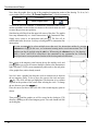
Construction Lines are the core elements of the T-FLEX CAD parametric model.
These are “thin” base lines that define the parametric framework of a drawing. The
construction lines include infinite straight lines, circles, ellipses, splines, offset lines,
function curves, and paths. They are displayed as dashed lines.
The in-depth description of the construction line types and their creation techniques
is given in the following chapters. The particular ways of creating construction lines
define the behavior of the drawing as the user modifies location of any construction
line. This is due to interdependencies among the construction lines that are
established at their creation.
A Node is a point whose placement is defined by a particular way of creation and by
interdependencies with other entities in the model. Nodes are also the core elements
of the T-FLEX CAD parametric model.
Typically, nodes are created at construction line intersections.
The nodes are directly involved in defining the parametric model that will drive other construction entities.
Examples of such situations are: a line passing through a node at a specified angle to another line, a circle
passing through two nodes, etc. Modifying the location of one of the lines defining the node will cause the
node to adjust. This change will propagate on other construction entities related to the node. The nodes are
also used for defining the ends of the graphic line segments and other graphic entities.
Besides the nodes that are defined by intersections of pairs of construction lines, T-FLEX CAD supports
several other types of nodes whose creation techniques are described below. For now, let’s consider only the
difference between the “snapped” and “free” nodes.
The typical technique of creating a parametric model implies creating nodes at construction line
intersections. This technique is called “constrained drawing mode”. While in “constrained drawing” mode,
creating a node at some location will undergo automatic snapping to the nearest to cursor pair of construction
lines and their intersection.
Creating “free” nodes is a special drawing technique used in non-parametric drawing, such as sketching. This
will further be referred to as “free drawing mode”. While in “free drawing” mode, the nodes are created
exactly under the cursor, without snapping to construction line intersections.
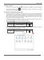
The “constrained drawing” mode is indicated by the icon
of the T-FLEX CAD automenu.
The “free drawing” mode is indicated by the icon
of the automenu. Switching between these modes is
done with <Ctrl><F> or by picking the respective automenu icon.
The recommended drawing technique is using the “constrained drawing” mode.
Avoid using mixed modes on the same drawing, as this may cause errors in
parametric modifications of the drawing.
Fixing Vector is a construction entity that helps defining the location and orientation of the
drawing that is used as a fragment in an assembly drawing.
24
Getting Started
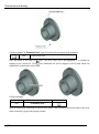
Connector is a construction entity that provides a placement reference for 2D fragments.
Besides the geometrical location (the origin of the coordinate system and the axes orientation),
a connector can keep additional data (both the dimensional and non-dimensional) that is
necessary for “plugging in” the 2D fragments. These data are stored as a list of named values
that can be either fixed constants or modifiable parameters. As for the parameters, their names
within the connector are significant in the following way: assigning same names to the
external parameters of the element to be connected makes these parameters assume the values
of their counterparts in the connector.
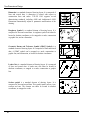
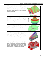
Graphic Entities
Graphic Lines are the lines constituting the actual drawing of the
drawing. Graphic lines include straight segments bound by a pair of
nodes, full entities, such as circles, closed splines and so on, except for
the infinite straight lines, and the portions thereof bound by pairs of
nodes, also splines through nodes.
The graphic lines may be of various types (main solid, thin solid,
dashed, dotted etc. They are snapped to nodes and construction lines.
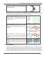
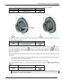
Hatches and Fillings are closed-contour single-connected or multipleconnected areas filled with various patterns or colors.
Hatch contours are snapped to nodes and construction lines. They
adjust to node location modifications. The filling pattern also
regenerates automatically as the contour changes.
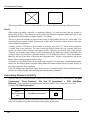
Text is a single-line or multi-line textual data input via a text editor or
directly in the drawing window. Either way of input supports various
fonts. Besides, T-FLEX CAD supports use of paragraph formatting
and other operations. A text can either be located in absolute
coordinates and thus independently from the construction entities, or
be snapped to construction lines and nodes.
ТЕXТ
Table
Table is an element of drawing layout. It is composed of lines and
textual data. Tables are created by the same command as text. A table
can either be located in absolute coordinates and thus independently
from the construction entities, or be snapped to nodes.
25
Two-Dimensional Design
Dimension is a standard element of drawing layout. It is composed of
lines and textual data. A dimension is created with respect to
construction lines and nodes. T-FLEX CAD supports several
dimensioning standards, including ANSI and Architectural ANSI.
Dimensions automatically adjust to parametric modifications of the
drawing.
Roughness Symbol is a standard element of drawing layout. It is
composed of lines and textual data. A roughness symbol can either be
located in absolute coordinates, or be snapped to a node, construction
or graphic line, and to a dimension.
Geometric Datum and Tolerance Symbol (GD&T Symbol) is a
standard element of drawing layout. It is composed of lines and textual
data. A GD&T symbol can be snapped to a node, construction or
graphic line, and a dimension, or located in absolute coordinates.
Leader Note is a standard element of drawing layout. It is composed
of lines and textual data. A leader note can either be located in
absolute coordinates, or snapped to a node, construction or graphic
line.
Section symbol is a standard element of drawing layout. It is
composed of lines and textual data. This symbol marks various views,
sections and cuts. The element can either be located in absolute
coordinates, or snapped to a node.
26
Getting Started
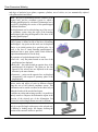
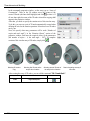
Fragments are T-FLEX CAD drawings that are used in other
drawings in subassemblies and assemblies. Any T-FLEX CAD
drawing can be used as a fragment.
A parametric fragment in T-FLEX CAD is a drawing that can be
inserted (assembled) into another drawing to a specified location and
with modified parameters. The fragment appearance shall change to
satisfy the parameter values. In order to create parametric fragments,
the user needs to follow certain rules described below.
Pictures are graphic images saved in various file formats.
Copy is an element duplicating the original, except for the different
transformation parameters.
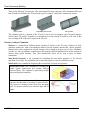
Controls are special elements in T-FLEX CAD used for creating userdefined dialog boxes customized for controlling external parameters of
a parametric model.
27
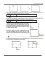
Two-Dimensional Design
Drawing View is a T-FLEX CAD entity that displays the content of
one drawing page on another page, appropriately scaled. This is a
rectangular area of specified size that will contain the other page
image. The main purpose of this element is combining in one drawing
several elements of different scale. A common use of the Drawing
View is for creating enlarged detail views.
Drawing View
Auxiliary Elements
Variable is a system element for specifying non-geometrical dependencies between the various parameters.
One main use of the variables is assigning their values to the construction line parameters. Consider, for
example, a line parallel to a given line, at a certain distance. This distance can be defined not only by value,
but via a variable as well.
Database is a table of information ordered in a certain way. Databases are used for storing information
required in the drawing.
Reports are textual documents that are created with the T-FLEX CAD text editor. Reports can include the
system variables and are used for creating various text documents.
Drawing Techniques
A T-FLEX CAD drawing can be created in one of the following ways:
Parametric Drawing. This is the recommended drawing technique in TFLEX CAD. Take the advantage of parametric design capabilities of TFLEX CAD to create a drawing that can be easily modified according to
your design intent. Such a drawing can also be added to a parametric model
library to be later used in other, more complex drawings. In the latter case,
one can specify a new location for the drawing as a fragment, and modify
parameters to obtain a desired shape.
Non-parametric Drawing (Sketch). This is a conventional drawing similar
to those created by most CAD systems. This drawing is created by using the
standard set of functions for plotting different basic entities (straight lines,
arcs, circles, ellipses, splines etc.) and by using the mechanism of objects
snaps. These drawings do not have advantages of parametric drawings as far
as efficient modification of parameters (dimensions) is concerned, however,
in certain cases creating these drawings saves time and can give the benefit
when significant subsequent modification is not required.
28
Getting Started
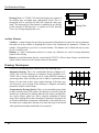
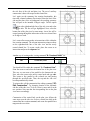
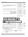
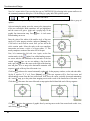
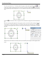
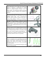
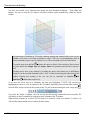
Creating Parametric Drawing in T-FLEX CAD
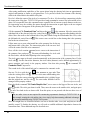
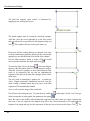
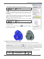
Creating a drawing in T-FLEX CAD begins with creating construction
entities. Construction entities can be created by various means. First, create
the base construction lines that will be used as a reference for additional
construction lines. The base lines can be vertical or horizontal. Next, create
straight lines and circles dependent on the base lines. For instance, construct
parallel lines, tangent circles, etc. The way in which additional lines are
created is stored in the model. The line intersections provide reference
locations for nodes that need to be created for further construction.
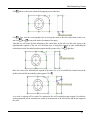
More straight lines and circles can then be created referencing the earlier ones in various ways. A line, for
instance, can be created through two nodes; a circle can be drawn through a node and tangent to a line. All
these construction steps are stored, and in future the thus created entities will be adjusting to the base and
other entity modifications according to their creation history.
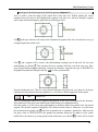
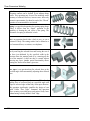
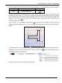
Thus, the early stage of creating a drawing involves building parametric
dependencies among construction entities that become the parametric
framework of the drawing.
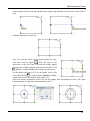
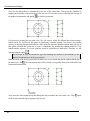
Once the construction framework is built, proceed with drawing the graphic
entities. Create line segments, arcs and circles by drawing over the
construction lines, snapping to nodes.
Once the actual drawing graphics is complete, proceed with the drawing
layout arrangement. Create dimensions referencing construction lines and
nodes. Define hatch contours, their filling patterns and other particulars.
Add text entities. When placing text use snapping to nodes and construction
lines if desired. This would be necessary if a text is supposed to move
together with the drawing graphics.
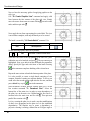
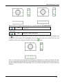
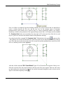
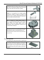
Further, define GD&T symbols, roughnesses and leader notes. Finally, a complete parametric drawing is
created and can further be modified. One can vary construction entity parameters, such as distances between
parallel lines, angles between lines, radii of circles.
The graphic entities will subsequently adjust with the construction ones they reference. Thus, a family of
variations of the original drawing can be created. All the rest of the drawing layout will also adjust
accordingly, all done in an instant.
Note that the above scenario for creating a parametric drawing in T-FLEX CAD is just one
recommended technique. One can create construction entities and graphic entities in an arbitrary
sequence. What is important is that the graphic entities are constrained to the construction ones.
The following chapters will tell how to use variables as drawing parameters, how to create an assembly from
fragments, and much more.
29
Two-Dimensional Design
Creating Non-Parametric Drawing (Sketch) in T-FLEX CAD
This technique implies quick sketching of the drawing graphics, completely avoiding preliminary creation of
the construction entities.
Sketching supports object snapping and provides dynamic hints that
make the drawing process simple and slick. However, thus created
drawings do not share the advantage of parametric drawings in the
capability of parameter (dimension) modifications. Creating nonparametric drawings may be somewhat preferable in the cases when no
significant modifications are expected.
Fast Drawing Creation. Automatic Parametrics
Another method of drawing creation combines the previously described methods – it is used for creating
construction-based parametric drawings using commands of non-parametric sketch. The user creates only
image lines, using object snapping. T-FLEX CAD automatically “puts” necessary geometrically related
construction lines under these image lines. The program defines construction types from the snapping used
on creation. For example, for a straight image line parallel to another line the program creates construction
line parallel to the construction line of the original image line. The resulting image line will lie on the new
construction with parametric relation to the original image line.
Quick Reference on User Interface
This section provides quick reference to T-FLEX CAD while assuming user familiarity with PC operation in
general, and some CAD experience as well.
Getting Help
The answers to the questions arising during operation can be got by the following means:
• The current command help can be invoked by pressing <F1> key, or by selecting menu
“Help|Current”. Pressing <F1> key when no command is active, or selecting “Help|Contents”
invokes the help contents.
• While within a command, the status bar displays hints and prompts.
• Pop-up help appears when the mouse is placed over an icon, a toolbar or other control element for a
brief time. This help message tells the name of the element pointed at, or other related information.
Mouse Interface. Context Menu
T-FLEX CAD operation is mainly performed by mouse. The keyboard is used for inputting numerical
values, names, and, in certain situations, for keyboard command accelerators (see below).
Using Left Mouse Button
30
•
Pointing cursor at an icon and pressing
•
Pointing cursor at an item of the textual menu and pressing
•
Pointing cursor at a 2D construction or graphic entity in the drawing window and pressing
this entity and activates its editing command.
invokes the respective command.
also does the command call.
selects
Getting Started
•
Pointing cursor at a 2D entity and double-clicking
•
Pointing cursor at an entity and depressing and holding
moves the entity.
•
Subsequent clicking
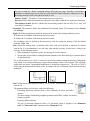
on 2D or 3D entities while holding left <Shift> key selects a group of
entities.
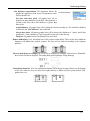
A group of 2D entities can be selected by “box selection” that occurs when the mouse with the
depressed
is dragged across the drawing window. The entities will be selected that are entirely
within the selection box.
If the mouse is moved from left to right the entities will be selected that are entirely within the
selection box. The box is drawn with continuous line.
When mouse moves from right to left, the entities are selected with the “cutting” box. This means that
the elements both entirely and partially within the selection box will be selected. The box is drawn
with the dashed line in this case.
•
•
invokes the “Entity Parameters” dialog box.
To unselect one entity in a group of selected, click on it with
while moving the mouse (“dragging”)
while holding left <Ctrl> key.
•
Pointing cursor at a selected group of entities and clicking
or double-clicking
starts moving
the selected entities.
• Managing libraries and arranging toolbars can be done using Drag&Drop mode. This is done by
pointing cursor at an element, depressing and holding , and moving to a new location.
For more information, refer to the appropriate volumes of the documentation.
Using Right Mouse Button
•
cancels the last action or quits the command. Certain
While within most commands, pressing
commands, as, for instance, the spline creating command or the hatch creation, allow user
customization of the action performed by the command on the
click. This could be quitting entity
creation, canceling last selection, or completing a sequence of inputs.
•
If no command is active, pressing
invokes context menu. This menu consists of the currently
available commands for the given entity. The set of items of the context menu will depend on elements
the cursor is pointing at. Thus, it will be different when the cursor is pointing at drawing entities from
when the cursor is over a menu area, or toolbar area, or control window area of T-FLEX CAD, etc. To
launch a command, point the cursor at the desired line of the context menu and press .
31
Two-Dimensional Design
•
The context menu can also be invoked while working with dialog boxes (see the topic “Context Menu
for Dialog Box Items” in the chapter “Customizing Drawing”).
The described right mouse button actions are set as defaults, but can be customized. To do so, go to
“Customize|Options…” (“Preferences” tab). For more information, refer to the chapter “Customizing
System”.
Additional Functions:
If the mouse has a wheel middle button then zooming in/out on the drawing can be done by scrolling the
wheel, and panning – by dragging the mouse with the wheel button depressed.
Calling a Command
A command call in T-FLEX CAD can be performed by the following means:
• Using an icon on a toolbar;
• Selecting an item in the textual menu;
32
Getting Started
• Typing a keyboard accelerator sequence.
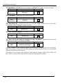
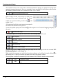
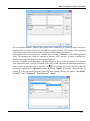
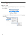
In this volume, any T-FLEX CAD command description will begin with a table describing these three ways
of calling the command. For instance, consider the command “ESA: Select all elements in current
View”. The table will appear as follows:
Keyboard input
Textual Menu
<ESA>,
<CTRL><A>
“Edit|Select All”
Icon
The three columns of the table contain the respective calling instructions.
The first column indicates the keyboard accelerator for the command for inputting the command from the
keyboard. All key strokes are shown together within one pair of angle brackets. Also, if defined for the
command, a standard function key combination is entered next. Each key in the function key combination is
shown in its own angle brackets.
The second column contains the access sequence for the command via the textual menu. The name before
the dividing line is the name of the appropriate group item in the menu bar. It is followed by the item name
in the pull-down menu that stands for the command. The menu item name may be different (abridged) from
the full command name, as is, for instance, the item name “Select All” versus the command name “Select all
elements in current View”.
The third column of the table contains the icon image for the command. Normally, the particular toolbar
containing the icon has the same name as the menu bar group item. For user convenience, a popup with the
command name appears when the cursor is briefly held over an icon. Once a command is activated by
pressing
on its icon, the icon stays “pushed” up until completing the command or switching to another
command.
Note: the keyboard accelerator combination is input by pressing the keys sequentially, while the
function key combination is pressed simultaneously, i.e. the first key is depressed and held while
pressing the second key.
The accelerator sequence for a command can be watched in the prompt field of the status bar when selecting
the command in the T-FLEX CAD menu bar or a toolbar. If a function key combination is defined, it is
shown on the textual menu item button at the right of the name. Any command allows defining or modifying
such combination. See “Customizing System” chapter, “Customizing Toolbars and Keyboard” topic,
“Keyboard” tab.
When inputting a command by typing, make sure the system is not within another command, and the status
bar is empty.
33
Two-Dimensional Design
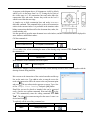
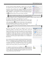
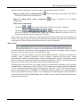
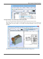
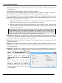
Each command has an additional set of options and
subcommands that can be accessed via the automenu or from
keyboard. The keyboard accelerators appear on the pop-ups by
the respective commands.
Some commands can be conveniently accessed from the
context menu. The context menu is invoked by pressing
after selecting one or several elements. The context menu
contains a list of commands available with the given selected
group.
34
Getting Started
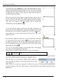
Canceling a Command
The last action can be cancelled by pressing
the command. Alternatively, use the
field in the status bar and the automenu.
in the drawing area or <Esc> key. Repeated pressing quits
icon of the automenu. Canceling a command clears the command
Starting System, Saving Drawing, Exiting System
Upon the start of the system the dialog box “Start Page” appears on the screen. It has been explained how to
work with this dialog box at the beginning of this chapter. It is worth mentioning again that this dialog box
allows creating new documents on the basis of templates already existing in the system, and it shows the list
of the recently used documents (with the possibility of opening them). Also, this dialog box has various
links, which can be useful in working with the system.
In addition to the dialog box “Start Page”, to create new documents and open already existing ones, the
system commands gathered in the textual menu “File” can be used.
“FN: Create New Model” command allows to create a new document:
Keyboard input
Textual Menu
<FN>,
<Ctrl><N>
“File|New 2D Model”
Icon
“FP: Create New Document Based on Prototype” command displays a dialog box that allows to
select a prototype file for the new document:
Keyboard input
Textual Menu
<FР>
“File|New From Prototype…”
Icon
35
Two-Dimensional Design
“O: Open Model” command brings up the standard “Open” dialog box to open a document for editing:
Keyboard input
Textual Menu
<O>,
<Ctrl><O>
“File|Open…”
Icon
“SA: Save Model” command saves the current document:
Keyboard input
Textual Menu
<SA>,
<Ctrl><S>
“File|Save”
Icon
“SV: Save Model As” command allows the user to save the current document into a new file with a
different name without changing the original document:
Keyboard input
Textual Menu
<SV>
“File|Save As…”
Icon
“SL: Save All Modified Models” command saves all currently open documents:
Keyboard input
Textual Menu
<SL>
“File|Save All”
Icon
“SY: Save current document as prototype for new documents” command saves the current
document as a prototype for creating new documents:
Keyboard input
Textual Menu
<SY>
“File|Save as Prototype”
Icon
Once this command is called, a dialog box appears on the screen. This dialog allows the user to specify the
name for the prototype file, specify the tab in this dialog box for this prototype or create a new tab if desired,
and also delete unnecessary files and tabs.
The prototype files are located in the “Prototypes” folder under the “Program” folder off the T-FLEX CAD
home. This is exactly the folder whose content is displayed in the dialog box by default.
36
Getting Started
A prototype folder can be specified by the command “SO: Set System Options”, “Folders” tab.
“PS: Show Model Properties” command displays all properties of the current document, and allows to
input a brief comment:
Keyboard input
<PS>
Textual Menu
Icon
“File|Properties…”
“File|Recent Files” displays the list of files open during previous sessions. Select a file name in the list to
open. The number of displayed recent files can be set via the “Customize|Options|Preferences”
command.
“FCL: Close Model” command closes the current document:
Keyboard input
<FCL>
Textual Menu
Icon
“File|Close”
A document can also be closed using the button
, located in the top-right corner of the document window.
“FI: Exit system” command closes the T-FLEX CAD session:
Keyboard input
Textual Menu
<Alt><F4>
“File|Exit”
Icon
The system queries the user whether to save modified documents (if any) before exiting.
Function Keys
Certain frequently used commands are bound to function key combinations, as follows:
<F1>
Get reference information (help) on the current command
37
Two-Dimensional Design
<Alt><F1>
Get information on the selected element(s)
<Ctrl><S>
Save document
<Ctrl><O>
Open document
<Ctrl><N>
Create new document
<Ctrl><P>
Print document
<Ctrl><F7>
Recalculate parameters of the current document
<Alt><F7>
Regenerate 3D model
<F3>
Call “ZW: Zoom Window” command. This is an instant command
that can be called while within another command. The previously
active command continues after this command.
<Ctrl><Shift><PgUp>
Zoom in
<Ctrl><Shift><PgDown>
Zoom out
<Ctrl><Shift><Left>
Pan left (moves the model left)
<Ctrl><Shift><Right>
Pan right (moves the model right)
<Ctrl><Shift><Up>
Pan up (moves the model up)
<Ctrl><Shift><Down>
Pan down (moves the model down)
<Ctrl><Shift><Home>
Fit to page
<Ctrl><Shift><End>
<F7>
<Alt><BackSpace> or
<Ctrl><Z>
<Ctrl><BackSpace> or
<Ctrl><Y>
Fit all objects
Call “RD: Update Model Windows” command
Call “UN: Undo Changes” command
Call “RED: Redo Changes” command
Please note that the above command bindings can be changed via the “Customize|Customize…|
Keyboard” command.
38
Brief Introductory Course
B RI EF I N TRO DU C TO RY C O U R S E
This chapter introduces various drawing techniques. The manual describes all necessary steps in the drawing
process. Once you start drawing with T-FLEX CAD, you will have an opportunity to fully appreciate the
advantages of this system. Further you will learn the basic commands and principles of creating a drawing
with the aid of T-FLEX CAD.
T-FLEX CAD supports creation of two types of drawings: parametric and nonparametric (sketches). The
mainly used type is the parametric drawing.
It takes somewhat more time resources to create a parametric drawing; nevertheless, later on such drawing
will be easily modifiable as you desire. A nonparametric drawing (sketch) can be created faster. Its creation
method is similar to the ways of drawing in some other CAD systems. However, nonparametric drawings do
not possess the advantage of effective parameter (dimension) modification. Therefore, this method is
recommended to use in the cases when no significant modifications to a drawing are expected.
To speed up creation of parametric drawings, the system supports the use of automatic parameterization.
This mode allows constructing not too complicated parametric drawings just like nonparametric ones: all you
do is create graphic lines using object snapping. The construction lines constrained by the parametric relation
will be automatically “slipped under” the graphic lines by the system.
Three approaches to creating a T-FLEX CAD drawing will be reviewed below: creating a parametric
drawing by the traditional method (that is, with the manual creation of construction elements), creating a
nonparametric sketch drawing, and creating a parametric drawing in the automatic parameterization mode.
Creating Parametric Drawing
The following diagram shows a drawing to be created. It is a plate
with a through hole of conical shape. The drawing will be defined
parametrically so that any modifications will automatically reflect
on all projections.
Let’s begin with the main (elevation) view of the plate. First, create
the necessary “thin” construction lines, and then draw the graphic
lines on top. Next, create the other two views using the construction
lines of the main view. This creates a dependency between the views
so that the two views automatically adjust to the main view
modifications. Finally, apply text and dimensions.
As was mentioned, any command can be called by a number of
ways. It can be typed on the keyboard, selected from the textual
menu, or picked on a toolbar.
Let’s begin with the command “L: Construct Line”. To invoke the command, use:
Keyboard
Textual Menu
<L>
«Construct|Line»
Icon
39
Two-dimensional Design
Pick the icon
at the top of the automenu. A crosshair appears that
follows cursor dynamically. The current coordinates of the crosshair
crossing point are displayed in the status bar. There are several ways to
define the crossing point. One is to simply place the cursor near the center
of the drawing window and press . To define the crossing point more
precisely, specify its coordinates in the property window. The coordinates
can also be specified via a parameter dialog invoked by typing <P> key or
picking the icon
in the automenu.
As a result, two crossing construction lines will be created. Besides, a node is created at the intersection
point. These lines make the basis of the view being created. The line parameters represent the absolute
coordinates. The view can be moved around on the drawing by moving the base lines.
Do not use more than two base lines on the main (independent) view, and more than one base line
on the views defined by projections. This will insure freedom in placing the drawings.
A T-FLEX CAD command stays active up until it is quit or another command is called. Quitting the
once) cancels the crosshair rubberbanding, but the line creation command
crosshair mode (as by pressing
stays active. After canceling the crosshair mode, move the cursor close to the vertical line. The line will get
highlighted, and a pop-up help will appear next to cursor displaying the name of the highlighted entity. This
is object snapping in action. This behavior relieves the user from typing on keyboard or using the automenu
buttons.
The object snapping is on by default when starting the application. To set or unset this mode
manually, use the button
on the “View” toolbar.
Pressing
now starts rubberbanding of a line that follows the cursor while staying parallel to the selected
one. We are now creating a line parallel to a vertical line. Such a relationship between the two construction
lines, established at the creation time, is an example of an important feature of T-FLEX CAD system. This
defines behavior of a set of construction entities under parametric modifications.
Place the new line at the left of the highlighted vertical line by pressing . The exact value of the distance
can be specified in the property window or parameter dialog box. The newly created line will become the
left-hand side of the part.
Pressing
once cancels the parallel line creation mode, yet the line
creation command stays active. (Otherwise, call it again.) Next, move the
cursor toward the horizontal line and press . The line is selected as a
reference for a parallel line to be created. Move the cursor up, specify an
exact value of the distance, if desired, using the property window, and press
fixing the top side of the part.
The next step is to round a corner of the plate with a fillet. For this purpose, let’s use the command “C:
Construct Circle”. Call the command via
40
Keyboard
Textual Menu
<C>
«Construct|Circle»
Icon
Brief Introductory Course
To draw the fillet at the upper-right corner of the plate, construct a circle
tangent to the top and the right-hand-side lines. Move the cursor to the top
line and press
or <L>. This starts rubberbanding of a circle whose radius
adjusts as the circle follows the cursor while the line tangency stays intact.
This means a circle is being constructed that is tangent to the top line. Any
future modifications of the top line location will not break the circle
tangency condition.
Next, move the cursor to the right-hand-side line and again press or <L>.
Now, the circle becomes “tied” to the two construction lines and keeps the
fixes the current circle
tangencies while being rubberbanded. Pressing
radius. The exact value of the radius can be specified in the property
window.
If the resulting construction does not match the illustration, use “UN: Undo Changes” command,
Keyboard
Textual Menu
<UN>,
<Ctrl><Z>,
«Edit|Undo»
Icon
<Alt><BackSpace>
Each call to this command brings the system one step back. If this command was called mistakenly, its
action can be reversed with the command “RED: Redo Changes”,
Keyboard
Textual Menu
<RED>,
<Ctrl><BackSpace>
Icon
«Edit|Redo»
This command restores the action that was mistakenly undone.
One can remove all construction lines and start creating a drawing from the beginning with the command
“PU: Delete Unused Construction”:
Keyboard
Textual Menu
<PU>
«Edit|Purge»
Icon
This command will delete all construction entities and allow to start drawing anew. A specific construction
entity can be deleted using command “EC: Edit Construction”:
Keyboard
Textual Menu
<EC>
«Edit|Construction|2D
Construction»
Icon
Once the command is called, select the entity and delete it by pressing <Delete> key on the keyboard or
by picking the icon
in the automenu.
41
Two-dimensional Design
Now, draw the graphic lines on top of the completed construction portion of the drawing. To do so, let’s
create graphic lines by calling “G: Create Graphic Line”. Call the command via
Keyboard
Textual Menu
<G>
«Draw|Graphic Line»
Icon
Note that the previous command is automatically terminated when calling
another command via the toolbar icon button or the textual menu (no need
to cancel the previous one explicitly).
Start drawing solid lines from the upper-left corner of the plate. The graphic
lines snap automatically to a closest intersection of the construction lines.
Simply move cursor to an intersection and press . The line will be
rubberbanded after the cursor. Just keep selecting nodes or construction line
intersections.
It is not recommended to select multiple (more than two) line intersections neither by pressing
<Enter> nor by . In this case, we recommend creating nodes at such intersections first. The
graphics can then be applied using the <N> key. When using the <Enter> key in “free drawing”
mode, a “loose” node will be created that is not constrained to any construction line. Following
these tips insures correct parametric function of the drawing under modifications.
Move cursor to the tangency point between the top line and the circle, and
press . What you see on screen now should be similar to the illustration at
right. Note that T-FLEX system automatically adds nodes to the end points
of the graphic lines, unless already created.
Now let’s draw a graphic line along the circle to construct an arc between
the two tangency points. To do so, move the cursor to the circle and press
<C> key. The circle will then get highlighted. The direction of arc creation
depends on the position of the cursor when selecting the circle. To change
the arc direction, press the <Tab> key.
Place the cursor just above and to the left of the second tangency point as
shown.
Then press , and the graphic arc will be created in the clockwise (CW)
direction, spanning to the second tangency point. The result should look like
on the diagram.
42
Brief Introductory Course
Continue drawing. Select with
the lower-right corner of the plate, then
the lower-left one, and finish the construction in the upper-left corner where
the drawing started. To complete the command press .
The drawing should look as shown here.
If applying graphic lines did not come out as desired, edit the graphics using the command “EG: Edit
Graphic Line”. Call as follows,
Keyboard
Textual Menu
Icon
<EG>
«Edit|Draw|Graphics»
Move the cursor to one of the lines to be edited, and press
pressing <Delete> key or picking the icon
. This selects the line. It can then be deleted by
in the automenu. Repeat for each line to be edited. If a
whole area is to be edited, use box selection. To select by box, press where one of the box corners should
be, hold and drag to the desired location of the opposite corner, then release the button. As you drag the
cursor, it rubberbands a rectangle of the selection box. The elements will be selected that are fully within the
box. All these elements can be deleted at once.
To apply graphic lines again, call the command “G: Create Graphic Line”. To redraw the screen at any
moment use the <F7> key, in case not all lines are displayed properly after editing.
Once the desired image is obtained, proceed to the next step of drawing creation. The drawing can be saved
preliminary with the help of “SA: Save Model” command:
Keyboard
Textual Menu
<SA>
«File|Save»
Icon
Congratulations! You have accomplished your first drawing in T-FLEX CAD. Now let us briefly describe
the system editing capabilities.
The current drawing uses five construction entities that define the shape and size of the part. These are the
left-hand side, the right-hand side, the top, the bottom and the fillet radius. To modify construction entities
call the command “EC: Edit Construction”:
Keyboard
Textual Menu
<EC>
«Edit|Construction|2D
Construction»
Icon
Move the cursor to the left-hand-side vertical line and press . The line gets highlighted. As you move the
cursor left to right, the line will move along. Specify the new position of the line by pressing . The width
of the plate will change. Note that modifying locations of construction entities causes instant update of their
respective “snapped” graphic lines. If you try to move the right-hand side of the plate then the whole plate
will move. This is because the left-hand side was created as a dependent of the right-hand one, and the
dependency stays as the right-hand side is modified. However, the left-hand side can move independently of
the right. Try such manipulations with other construction entities, including the circle. As the construction
entities move the size and shape of the plate will be changing while maintaining the dependencies defined at
the construction time.
43
Two-dimensional Design
After testing modification capabilities of the system please bring the drawing back into an approximately
original configuration as shown on a diagram above. Let’s proceed with the next element of the drawing,
which is the conical hole in the middle of the plate.
First, let’s define the center of the circle to be constructed. To do so, let’s do auxiliary construction to define
the center point of the plate. T-FLEX CAD provides a handy command to create a line in the middle of two
others. For two parallel lines, this command creates a parallel line in between at equal distances to the two.
For intersecting ones, the resulting line passes through the intersection at equal angles to the two original
lines. Thus, the new line appears as the symmetry line for the two.
Call the command “L: Construct Line” and choose the icon
in the automenu. Move the cursor to the
right-hand side of the plate and select the vertical line by . A parallel line appears rubberbanding after the
cursor. Move the cursor to the left-hand side of the plate without fixing the rubberbanded line. Now, select
the left-hand-side vertical line with . This creates a new vertical line on the drawing that is the symmetry
line for the two selected ones.
Follow same way to create a horizontal line as the symmetry line for the top
and bottom sides of the plate. The intersection point of the two new lines
will be the center of the hole to be constructed.
Next, call the circle creation command, move cursor to the intersection of
the symmetry lines, and press . This starts rubberbanding of a circle with
the fixed center, with the radius adjusting to the cursor position.
The circle center snaps to the node created automatically at the intersection of the symmetry lines. Fix the
circle with . Just like line-to-line distances, the circle radius (diameter) can be defined approximately by
the command “C:
mouse operation, and exactly in the property window. Note that after pressing
Construct Circle” stays active.
The second circle of the conical hole can be constructed as concentric to the
first one. To do so, pick the icon
in the automenu or type <O>. Then
select the existing circle with . The new circle starts rubberbanding after
the cursor. Place the cursor so that the rubberbanded circle is slightly bigger
than the original one, and fix with . The exact radius difference can be
managed via the property window.
Proceed with the command “G: Create Graphic Line”, move cursor to the bigger of the two circles, and
press
or <C>. The circle gets drawn in solid. Then, move the cursor to the smaller circle, and again press
or <C>. Now both circles are drawn solid. From this point, we can proceed with the two other views of
the plate.
The two other views are not required for constructing a parametric drawing in T-FLEX CAD. In
this example, creating the side and the plan views simply help demonstrating additional advantages
of parametric modeling using T-FLEX CAD system.
Since the straight lines are considered infinite, one can see that the other views (side and plan) are already
partially created. To finalize the drawing, we will need to establish additional dependencies between the
construction lines. These additional steps are described next.
44
Brief Introductory Course
Activate the line creation command and move the cursor to the
construction line defining the right-hand side of the plate. Select
it with . This highlights the vertical construction line and starts
rubberbanding of a new line parallel to the selected one. This
line will be the right-hand side of the plate side view. Fix it at a
desired location by pressing . As before, the exact distance
from the selected line can be specified in the property window.
The new line is created relative to the right-hand side of the plate on the main view. Therefore, when the
right-hand side of the plate is moved, the new line will follow, staying at the same distance. To place the new
line at a different distance, use the command for editing construction lines. After that, moving the right-hand
side of the plate will again preserve the new distance. The dependencies between construction entities stay
valid until redefined in the construction line editing command.
The next step is creating the line of the left-hand-side edge of the part on the side view. After completing one
line, a new line rubberbanding began automatically.
Note that the currently rubberbanded second line is also a
dependent of the plate right-hand-side line as the latter is still
highlighted. This is not our intention; therefore, press
to start
line creation anew. Select the last created line – the one marking
the right-hand side of the side view - by clicking
on it.
Rubberband the new line up to the approximate location, and fix
with , or enter exact value in the property window.
We recommend using specifically the right-hand side of the part main view as the base line, and construct all
the rest vertical lines with respect to it. In this way, the line-to-line distances will be positive which is
preferable in some situations.
Now let’s proceed with constructing the projection of the conical
hole. First, let’s create horizontal lines tangent to the top and
bottom of the inner and outer circles of the hole. These lines will
be used as guides for the side view of the hole.
Press
once to restart line creation, move the cursor to the
horizontal symmetry line, and select it by pressing
or typing
<L>. The line gets highlighted. Rubberband the new line by
moving cursor to the outer circle and type <C>. The line is
created parallel to the horizontal symmetry line and tangent to
the circle.
Repeat the same sequence of actions three more times: for the
top tangency with the inner circle, and the two bottom
tangencies.
45
Two-dimensional Design
Now we have the necessary guides for applying graphics on the
side view.
Call “G: Create Graphic Line” command and apply solid
lines between the four corners of the plate side view. Simply
move the cursor from corner to corner clicking on each corner
node, and then quit with .
Next, apply the two lines representing the conical hole. The view
is now almost complete, with only the hatch yet to be created.
The hatch is created by “H: Create Hatch” command. Use
Keyboard
Textual Menu
<H>
«Draw|Hatch»
Set the following option, unless on by default,
<A>
Automatic Contour search mode
Then move the cursor to the top portion of the side view, place
within the area to be hatched, and press . The top contour gets
highlighted. Next, type <P> to invoke the hatch area parameters
dialog. Specify the type and scale factor of the hatch. Pressing
in the automenu completes hatching of the selected area.
Repeat the same actions to hatch the bottom portion of the plate.
It is also possible to create a single hatch consisting of two
contours, instead of creating two separate hatches. To do so, one
could select the second contour right after the first one, and then
press <End> key or pick
icon in the automenu.
Once the hatch is created, proceed with the plan view. Call the
line creation command “L: Construct Line”. Select the
bottom line of the main view in order to create dependency of
the plan view on the main view. Rubberband the new line to a
location below the main view and fix with . Then quit next
parallel line creation with .
Let’s try creating the plan view in such a way that modifications
of other views propagated on the plan view via the established
dependencies. The simplest way to create a dependency in
projective drawing is creating a slanted line at 45-degree angle to
46
Icon
Brief Introductory Course
the side lines of the side and plan view. The rest of auxiliary
construction is done with respect to this slanted line.
Let’s again use the symmetry line creation functionality, this
time with a slanted symmetry line in mind. Since the lines of the
side and the plan views are orthogonal, the resulting symmetry
line will pass at the intended 45-degree angle. Call the option
. Point at the right-hand-side line of the side view and select
with
or <L>. The line will get highlighted. Next, select the
bottom line of the plan view by same means. A new line will be
created passing through the intersection of the two selected lines
at 45 degree to each.
Let’s create all necessary nodes at intersections while within the
line creation command. The relevant intersection points are those
on the right-hand-side line of the side view and the newly
created slanted line. To create a node, place the cursor at an
intersection and press the <Space> bar.
Another way of creating nodes is using command “N: Construct Node” via:
Keyboard
Textual Menu
<N>
«Construct|Node»
Icon
You should still be within the command “L: Construct Line”.
Point the cursor at and select the bottom line of the plan view.
This way we can create a line parallel to the bottom-side one.
Now, move the cursor to the newly created node and type <N>.
This creates a line parallel to the selected one and passing
through the specified node. Thus, the top and the side view
become parametrically related.
To witness this, call the construction line editing command “EC:
Edit Construction”. Try changing location of the left-handside line of the side view. To do so, select it, move and fix in the
new position. Note now that the corresponding line on the plan
view moves accordingly.
Construction of the conical hole on the plan view follows the
same steps as on the side view. Select a vertical line while in the
construction line creation command, and create four parallel lines
tangent to the two circles.
47
Two-dimensional Design
Now one can draw all graphic lines on the plan view. Use the
command “G: Create Graphic Line” to draw the perimeter of
the plan view.
Next step is to apply the two dashed lines corresponding to the
conical hole. Set the “HIDDEN” line type in the system toolbar.
Then create the two dashed lines representing the conical hole.
Now, let’s create centerlines. Call “AX: Create Axis” command:
Keyboard
Textual Menu
<AX>
«Draw|Axis»
Icon
Set the automenu option:
<I>
Use
Create Axis of two Graphics lines
to select the left and then the right-hand side of the
elevation view. Push the
automenu button. This creates a
centerline on the elevation view. Similarly, create a horizontal
centerline on the elevation view and those on the side and plan
views.
One could notice that all construction lines created so far were
infinite. For convenience, an option is provided in the command
“EC: Edit Construction” for trimming construction lines at
outermost nodes. This works as follows,
1. Call “EC: Edit Construction” command.
2.
Selecting one particular line and typing <T> or pushing
3.
Using option
48
trims all lines.
trims this selected line only.
Brief Introductory Course
4.
If you want to revert to the infinite line setting, call the command “ST: Set Model Status”:
Keyboard
Textual Menu
<ST>
«Customize|Status…»
Icon
Go to the parameter «Screen|Construction Lines|Length» and
set it to “Default infinite”. Alternatively, enter the command
“EC: Edit Construction”, select desired lines, type <P> and
specify an appropriate setting.
The diagram shows a drawing with construction lines trimmed. It
appears less crowded, although all necessary construction entities
are present. By default, construction lines are not output to the
printer or plotter, regardless of their length.
Next, let’s create the necessary dimensions on the drawing as
follows:
1. First, let’s create linear dimensions. Call the command “D: Create Dimension”:
Keyboard
Textual Menu
<D>
«Draw|Dimension»
Icon
One can select any pair of construction lines or graphic lines to create a linear or angular dimension. Select
the two outermost lines on the main view by . This starts rubberbanding of a dimension following the
button in the automenu. The
cursor motion. To change any dimension parameter, type <P> or push the
dimension parameters dialog box will appear on screen. Specify the desired parameters, close the dialog, and
fix dimension placement with . To change the size of the dimension string font, use the command “ST:
Set Model Status”, the tab “Font”. The font parameters can be specified on this tab for the elements that
did not have such parameters set originally.
2. Repeat the steps of the item 1 for the rest of the linear dimensions.
3. Diameter and radius dimension creation is also straightforward. While in “D: Create Dimension”
command, move the cursor to a circle to be dimensioned, and
type <C> or click . The circle gets selected, and a dimension
begins rubberbanding after the cursor. Switch between the radius
and diameter dimension types by typing <R> and <D> or
and
buttons of the automenu as appropriate.
picking
Typing <M> loops through the possible witness/leader line
configurations for the entity to be dimensioned. The <Tab> key
handles the direction of the dimension leader line jog. Point the
cursor at the desired location and press . The newly created
dimension will be displayed on the screen. Repeat this procedure
to dimension all circles.
49
Two-dimensional Design
4. After finishing construction of all major elements, one can hide all construction entities using the
command “SH: Set Levels”:
Keyboard
Textual Menu
<SH>
«Customize|Levels…»
Icon
This command controls visibility of various elements. An element visibility depends on the “level” at which
it is residing.
After calling the command, a dialog box appears on screen that allows setting a range of visible levels for
each element type of the model.
Think of levels as transparent films with images drawn on them. The complete drawing consists of all of
them overlapped. The system permits making one or more levels invisible, displaying only intended ones. A
drawing may consist from up to 255 levels enumerated from -126 to 127.
All elements in T-FLEX CAD are automatically created on the level “0”. One can re-assign any element to
another level at any time. In our example, we did not change levels of any element; therefore, all created
elements fell in the level “0”.
50
Brief Introductory Course
As appears on the diagram above, all elements are visible by default
whose level is in the range from 0 to 127. Setting the low limit of
the visible range to 1 for construction lines and nodes hides the
construction lines and nodes, because they reside on the level 0
which is not within the new range.
A simpler way to hide construction lines and nodes is to use a
dedicated command. This command hides or shows all construction
entities in the current window. It is preferable in the situations when
hiding construction should not affect the document data, rather, the
current window only.
It is thus possible to open the same document in several windows, and have construction entities displayed in
some windows, and hidden in others.
Call the command via
Keyboard
Textual Menu
<Ctrl><Shift><C>
«View|Hide Construction»
Icon
5. Let’s make a line of text containing the name of the drawing using command “TE: Create Text”. Call
the command via
Keyboard
Textual Menu
<TE>
«Draw|Text»
Icon
In the automenu of the command, turn on the option:
<D>
Create string text
A text can be “snapped” to any construction entity on the drawing in order to have it move together with the
drawing elements being modified.
Move cursor to the intersection of the vertical centerline and the top
line on the main view. Type <N> in order to snap the text to the
node at the intersection. Move the cursor to the text placement point
and press . The text editor window appears on screen. Type a line
of text “Sample Plate Drawing” and push [OK] button.
Should the text not be placed as intended, this can be corrected
at the
easily. Quit the text creation command. Point and click
text. This automatically starts the editing command “ET: Edit
Text”. The selected text starts moving after the cursor. Locate it as
desired and click .
To explicitly call the text editing command, use
Keyboard
Textual Menu
<ET>
«Edit|Draw|Text»
Icon
51
Two-dimensional Design
In this case, select the text to be edited after launching the command.
There is another way of creating a text, which is typing it directly in the drawing area. To do so,
enter the “TE: Create Text” command and set the option <Т> - “Create paragraph text” (icon
). Move the cursor to the intended location of the text and press . A rectangle starts
rubberbanding on screen that defines the text box. Define the intended area and click , then push
the
icon. A blinking cursor will appear in the box. Make sure of the correct input locale and
enter the intended text. Then push the
icon or <F5> key.
The drawing is now finished. One can try moving construction lines using construction editing command.
or specifying exact line location in the property
When editing, fix line new placement by either using
pick). Note that the whole drawing, including
window or parameters dialog (the latter accessible via the
dimensions, adequately responds to modifications. Changing diameters of the conical hole instantly reflects
on the two other views. Hatches also adjust to their defining contours. Now one can easily witness the
powerful capabilities brought in by the parametric technology.
From now, we will assign variables and expressions to the various drawing elements. Select the left-handside line on the main view by clicking .
The line will get highlighted, along with the one it is dependent on
by construction. Line editing command will automatically activate as
well. The two parameters are displayed in the property window. The
first one is the original distance, and the second is the current value
according to the cursor position.
Since the line was originally created as parallel to the left-hand side of the plate, the displayed distance is the
distance between the right and the left-hand side of the plate. Instead of a specific value, one can input a
variable. Type a variable name “W” instead of the value and press
<Enter> or [OK].
A new dialog window will appear requesting a confirmation for
the new variable to be created.
Please note that the variable naming is case-sensitive. A variable
“W” is not the same as “w”.
The created variable «w» and the value assigned for this variable
can be seen in the window “Variables” located, by default, under
the properties window. Point with a cursor at the number in the
column “Expression”, press
to enter the edit mode and specify
the value for the variable, for example, «170». The line will
move to a different location corresponding to the new value of
the plate width.
52
Brief Introductory Course
The same operations can be carried out in the dialog window of the command “V: Edit Variables”:
Keyboard
Textual Menu
<V>
«Parameters|Variables»
Icon
Similarly, define a variable “H” as the distance from the base line to the top side of the main view. Select the
line on the drawing by clicking
and enter the variable name in the property window. Now there will be
already two variables in the window “Variables”, and you can, by modifying their values, observe the change
in the drawing.
Try making an expression. In the window “Variables” place the cursor in the field “Expression” of the
variable «H» and press
to enter the edit mode. Specify the expression «W/2» instead of the numerical
value. This means that the value of “H” will be equal to the half of “W”. From now on, changing just the
value of “W” will automatically reflect on the value of “H”.
Next, let’s assign an “R” variable to the radius of the circle defining the fillet at the upper-right corner of the
plate. Select the circle on the drawing by . In the property window specify the radius as “R” variable.
After confirming its creation, in the window “Variables” set the variable to the following expression: W <
100 ? 0 : 6
This expression means that “R” equals 0 when “W” is less than 100, and equals 6 otherwise.
Let’s briefly explain the syntax of the expression. Its members are described as follows.
< - is the “less than” sign
? - means “then”, “in such a case”
: - means “else”, “otherwise”
The complete expression is written as
R = W < 100 ? 0 : 6
The value of “R” equals 0, if “W” < 100, and equals 6 for any other value of “W”. Therefore, there are only
two possible values of “R” - either “0” or “6”.
Check this on your drawing. Try setting “W” values greater or less than 100, and watch what’s happening.
Note that when the radius of the fillet equals 0, then the radial dimension automatically disappears. The
system does it for the user.
Therefore, one can create a variety of relations between variables, including quite complex ones, using just a
few basic terms. You will get to know all capabilities of the variables functionality in later chapters.
Creating Sketch, Non-parametric Drawing
We will use the same familiar drawing example of the plate with a conical hole. Let’s begin with
constructing the main view. Thereafter, we will create two projections, the “Left Side View” and the “Plan
View”, using object snapping mechanism.
In this case, all construction is done using the command “SK: Create Sketch”. Call the command via
Keyboard
<SK>
Textual Menu
Icon
«Draw|Sketch»
53
Two-dimensional Design
This command can be used to create either a sketch (nonparametric drawing) or a parametric drawing in the
automatic parameterization mode. Since we are going to create specifically a sketch, please make sure that
the automatic parameterization icon is switched off on the “View” toolbar
Automatic parameterization on/off
When creating a sketch, object snaps are widely used.
The control over snaps is performed with the “Snaps”
toolbar. To access this toolbar, press the icon
on the
toolbar “View”.
All snaps turned on by the present moment correspond to
the toolbar icons which have been pressed.
To turn off a pushed option, point at and click
the option:
on the respective icon. To turn off snapping completely, set
Clear all sketch Snaps
Unsetting this option sets all snaps on. In our exercise, the following snaps will be used:
Line Midpoint
Horizontal / Vertical
Orthogonal
Line Intersection
Horizontal/Vertical tangent
Push these icons on the “Snaps” toolbar. The object snaps can also be managed within the command “SO:
Set System Options”, using “Snaps” tab.
When creating line segments, arcs and circles, the point coordinates can be defined by simply clicking
the drawing area. To specify exact node coordinates, one can use the property window.
The two options are turned on automatically in the automenu while within the sketch creation command:
54
<J>
Continuous creation
<S>
Line
in
Brief Introductory Course
The first icon allows drawing continuously, so that the end of a just created
line becomes the start of the new line. This mode will stay active until the
user turns it off by pointing at the icon and clicking
. We recommend
keeping this option on for speedy sketching. The other option sets the
segment input mode. A black triangle in the lower-right corner of the icon
marks availability of more options. To access these encapsulated options,
press
and hold a bit longer, and a menu of options will appear.
Attention: the automenu may display any of the encapsulated option icons in the given position.
Usually this is the icon of the last used option among the encapsulated set.
In “Sketch” automenu, each set of encapsulated options corresponds to a group of actions related to sametype element creation, such as creating segments, arcs, or circles.
The cursor on screen appears as a little square. Move the cursor to the
intended location at the lower-right corner of the main view, near the middle
of the screen, and press . This creates the first node of a line segment and
starts rubberbanding the segment to be created. At the same time, the fixed
coordinates of the first point are displayed in the property window.
While sketching, consider leaving sufficient margins. This space will later be used for creating
dimensions.
Move the cursor upward. Note that the coordinates of the cursor are
dynamically updated in the property window, along with the vertical and
horizontal shifts from the start node of the segment. We can use the property
window for specifying exact location of the segment end. The end node can
be defined in several ways. One way is to enter absolute Cartesian
coordinates (X, Y) of the segment end node. Another way is specifying X and
Y shifts of the end node from the segment start (dx, dy). Yet another way is
to define the end of the segment in polar coordinates, or as a combination of
the other ways.
Let’s create the end of the segment by specifying its shift from the start point.
Make “dx” value equal to 0, and “dy” parameter equal to 100. The parameters
“X” и “Y” will instantly update with the absolute coordinates of the segment
end and get checkmarked. Checkmarking locks the value of the respective
coordinate in spite of cursor movements. The end node of the segment will be
displayed in the drawing window per the entered coordinate values.
To complete the end node input, press [Enter] or click
in the drawing
area. The first segment will be created. Move the cursor leftwards and place it
so that it snaps to the horizontal constraint with respect to the last created
node. The snap will be indicated by the specific glyph next to the cursor, and
a pop-up help message saying “Horizontal”.
55
Two-dimensional Design
To lock this snap, press <Space> bar. Then, a horizontal helper line will be
displayed passing through the node snapped to. The cursor will keep sliding
along this helper line as an unattached node. The same effect can be achieved
by setting the “dx” shift to 0 in the property window and locking the X
coordinate with the checkmark.
Place cursor on the side of the segment intended direction. Type the value of
the “dx” shift for the end node of the segment being created in the property
window. In our case, this value represents the width of the part and is equal to
-150, while “dy” equals 0. The new segment will be created upon
confirmation by pressing [Enter] or .
You are still within the segment creation mode. For further construction, you
need to move the cursor downward to a point where snapping occurs to both
horizontal and vertical constraints simultaneously. This will be indicated by a
special glyph next to cursor and pop-up help message. Press
. A new
segment is created.
Move the cursor rightward to snap at the very first created node, as indicated
by a glyph and the pop-up help, and press . We have thus completed the
perimeter of the main view. We are still in line rubberbanding mode, with a
new line stretching from the last created node to the cursor. Quit this line
rubberbanding by clicking .
Now you are still within continuous segment input mode, with snapping
active but no line rubberbanding after the cursor.
The next step is to round the corner of the plate. To do so, set the option:
<Ctrl+A>
Fillet
This option belongs to an encapsulated set and may not necessarily be displayed in the automenu. Instead, it
may be under the fillet/chamfer icon group (see explanation above).
Once the option is set, the property window changes appearance.
Now it provides the input box for the fillet radius. Set the radius
value equal to 31.
What is left now is to select two segments to be filleted. In our case, it is the top and the right-hand-side
segments of the plate. Once the second segment is selected, the fillet is created, and the segments trimmed
appropriately.
56
Brief Introductory Course
Now let’s draw the conical hole on the main view. To do so, let’s create two centerlines whose intersection
will define the exact location of the center of the hole. Set the option
<S>
Line
Once this is set, rubberbanding resumes with a line attached to the last created node. Reject this line by
clicking . To create centerlines, set the appropriate line type. Set the line type to DASHDOT in the system
toolbar or in the graphic line parameters of the dialog box. Call the dialog box by
<Р>
Set Graphic line Parameters
Then move the cursor to the left-hand-side graphic line segment to
get vertical snapping to one of the segment nodes, and slide the
cursor along the segment to its midpoint. When the cursor reaches
the midpoint, the glyph beside the cursor will change to indicate
this, along with the pop-up help.
Press
here. A node will be created at the midpoint, and a line
will start rubberbanding from this node. Move the cursor
horizontally to the right-hand-side graphic segment and stop at the
intersection of the horizontal and vertical projections of the two
nodes as shown on the diagram.
Press , creating a centerline and a node. Rubberbanding resumes from the latest node. As we do not intend
to construct another line through this node, quit rubberbanding with . Then follow the same steps to create
the vertical centerline, beginning at the bottom segment.
57
Two-dimensional Design
Now, let’s create circles. First, reset the line type to CONTINUOUS by selecting in the system toolbar or in
the command parameters dialog box. Call the dialog by typing <P>. Then pick the option:
<O>
Circle By Center And Radius
This is also an encapsulated option that may not be shown on the automenu, rather, be within a group of
options.
After activating the option, move the cursor to the intersection
of the two centerlines. Both centerlines will get highlighted,
and the cursor will gain a glyph and a pop-up help of the
graphic line intersection snap. Press
here. A circle starts
rubberbanding on screen.
Enter the value of the radius of the smaller circle of the cone
equal to 25 in the property window, and press [Enter] key.
A full circle is now fixed on screen. Now you are still in the
circle creation mode. Select the node at the two centerlines
intersection and create a circle of a bigger radius, 35. This
mostly completes creation of the main view of the part.
Now, let’s construct the left side view. Again, set the line
creation mode via the
option. Line rubberbanding resumes
on screen with the line attached to the end node of the last
created segment. Since we are not making a line from this
node, quit with . Move the cursor to the right of the drawing
area and place it so to snap to the horizontal constraint with
respect to a node of the top line of the main view.
Click here , and move the cursor horizontally rightwards. In the property window, set the end node shifts.
Set the Х equal to 35, Y to 0. Press [Enter] or . The new segment will be fixed on screen, and
rubberbanding resume from the last created node. Next, move the cursor vertically downward maintaining
the “vertical” snap, up to the point when snapping occurs with a node of the bottom line of the main view.
Click there , then move the cursor leftwards to snap against the left-hand-side end of the top segment.
Click
. Now close the perimeter of graphic lines by moving cursor to the first created node on this view,
and clicking
58
, and then
.
Brief Introductory Course
One-degree-of-freedom snaps can be locked by pressing <Space> bar.
Next, we need to create the image of the conical hole on the side view. Without quitting the current
command, move the cursor to the right-hand-side segment of the side view, and move along the segment
until it snaps to horizontal tangency against the top of the bigger circle
Click at this spot, then move the cursor to the left-hand-side segment of the side view and locate so to get
it snapped against the smaller circle.
Click , and a segment will be created, with rubberbanding resuming from its end node. For now, quit
rubberbanding by clicking . Then construct the lower segment of the hole view in the same way. Next,
using already familiar snapping constraints, construct the centerline, setting the line type to DASHDOT in
the graphic line parameter dialog box (the key <Р>) or in the system toolbar.
Proceed with the plan view. This view can be created in the same way as the side view. However, for deeper
exploration of non-parametric drawing capabilities, we will follow a different approach. Set the option:
<D>
Parallel Line
This is an encapsulated option in the segment creation group. If this icon is not displayed in the automenu,
find it under one of the group icons marked with a black triangle (see explanation above).
Once this option is set, the cursor starts rubberbanding an auxiliary infinite line parallel to the last created
segment. The reference segment is highlighted. The current reference suites us. Otherwise, we would reject
the system-selected segment with
and select an intended one to construct a parallel line. Make sure the
line type is back to CONTINUOUS in the graphic line parameter dialog (the key <P>) or in the system
toolbar. Move the cursor to get a snap against a node of the main view, and click
. A node will be created
59
Two-dimensional Design
at this point, and the auxiliary line will get fixed. Slide the cursor along the line up to the point of another
vertical snapping, and again click .
Thus, we have created the top segment of the plan view. A new auxiliary line starts rubberbanding after the
cursor, parallel to the newly created graphic segment, as indicated by highlighting. Move the cursor down,
and set the desired distance, equal to 35, in the property window, thus defining the thickness of the plate.
This will fix the auxiliary line with respect to the reference segment. Slide the cursor along the line, locating
as shown on the diagram.
Click , fixing the start node of the segment being created. Slide the cursor rightwards to get vertical snap
against the end node of the reference segment, and again click . The bottom segment will be created. At
, thus switching to normal
this moment, parallel line rubberbanding resumes. Now, set the option
continuous line input mode. A line will start rubberbanding, attached to the last created node. Move the
cursor upward to the top segment node, and click , and then . Next, connect the left-hand-side ends on
the plan view with another segment. Create the centerline and the lines of the conical hole projection in the
same way as on the side view. Doing so, maintain the appropriate line types.
60
Brief Introductory Course
What is left now is to apply hatch on the side view. Call the command “H: Create Hatch”:
<Н>
Create Hatch
<A>
Automatic Contour search mode
Set the option:
Then move the cursor to the top portion of the side view, place it in the middle of the area to be hatched, and
click
. The closed contour will be highlighted. Now move the cursor to the lower portion of the view, and
similarly select the other contour to be hatched. Then pick the
button.
Now, let’s create the necessary dimensions on the drawing. Dimensions are created on a sketch in the same
way as on a parametric drawing. One can select graphic lines instead of construction lines in this case. Let’s
skip the detailed description of this functionality, as it was described in depth as part of the main drawing
technique.
61
Two-dimensional Design
This completes creation of the non-parametric drawing. Further modification of its elements will not affect
the whole drawing. One would have to modify each view separately. The elements of such a drawing cannot
be related by variables. All other functionalities such as use of visibility levels, layers, hide/show
construction entities, etc. are fully supported.
Creating a parametric drawing in the automatic parameterization mode
We will use the same drawing as an example. The sequence of constructions will be the same as described in
the previous section of this chapter.
When working in the automatic parameterization mode, we will be creating only graphic lines (as when
constructing a sketch). Meanwhile, the system will be automatically "slipping" nodes and construction lines
with parametric relations underneath those graphic lines. What constructions to create and what
dependencies to use in relations is determined by the system based on the user-selected snaps and parameters
defined in the command's property window when creating sketched lines.
Call the command “SK: Create Sketch”. Make sure that the following snaps are enabled:
Construction
Line Midpoint
Horizontal/Vertical
Orthogonal
Graphic Line Intersection
Horizontal/Vertical tangent
To create a parametric drawing, the automatic parameterization mode must be turned On in the system. This
mode is enabled with the icon on the “View” bar:
Automatic parameterization On/Off
62
Brief Introductory Course
We will start with creating the main view of the plate. If necessary, enable the line segment creation option
in the command's automenu (if desired). Create the first point of the segment, corresponding to the
lower-right corner of the plate's main view. Please note that it was not a free node that was created at the
location of the click, rather, there are two crossed lines (vertical and horizontal), and a node at their
intersection.
For the second node of the segment, define the Yaxis offset (100) in the properties window. The
cursor will start moving along a horizontal
auxiliary line. Move it to the vertical construction
line going through the first segment node. When
the snap to the latter line engages (“Line …”),
click .
As a result, the second node of the created
segment will also be constructed as snapped. It
will lie on the intersection of the vertical line
created at the time of constructing the first node,
and a line parallel to the horizontal line of the first
node.
Please note, that, when selecting a snap, the system may offer the vertical snap to the first segment node
rather than snapping to the line (the order of displaying snaps is determined by the settings in the command
“SO: Set System Options”). To select the desired snap, do the following: briefly rest the cursor at the
location of the snap activation. After a brief while, the cursor will change its shape: the mark
and a
tooltip will appear next to it, showing the total number of object snaps found at this point. Using the mouse
wheel, you can scroll through those snaps. In the ongoing construction, select the desired snap from the list
of possible ones at a given point using the same method.
Create the second, horizontal, line segment with the length 150.
When constructing it, specify the desired offset along the Xaxis and use a snap to the line again.
If all was done correctly, then the created line segment will lie
on the line created at the time of constructing the second node
of the previous segment. Meanwhile, the second node of the
current segment will be constructed as one lying on the
intersection of the same line and a new line parallel to the very
first vertical line.
63
Two-dimensional Design
The third line segment, again vertical, is constructed by
snapping to two existing lines at once.
The fourth segment must be closing the described rectangle.
After that, move the cursor rightward up to the first created
node, as indicated by a special mark in the dynamic tooltip, and
click . This completes the base for the part's main view.
Please note, that the resulting drawing we obtained is the same
as when constructing a parametric drawing by the conventional
approach (as was described in the first section of this chapter).
Just like when creating a sketch, to create a fillet one would
need to quit the continuous line input mode (using ).
To create the fillet, let's use the option
. After activating the
option, set the fillet radius equal to 31 in the properties window.
After that, select two segments, at whose intersection the fillet
needs to be constructed (the top and the right-hand-side
segments of the plate) or the node (the rectangle vertex) at their
intersection.
This will result in constructing a graphic line – a circular arc
with a "slipped underneath" construction line-circle. Just like
when creating a common sketch, the extra pieces of the fillet
segments will be automatically trimmed.
Next, we will create the image of the conical hole.
We will start with creating the axes. To create the axes, enable the
option again. Set the “Axis” line type
).
in the system panel or in the graphic line parameters (the option
Move the cursor to the middle of the left-hand-side segment of the plate's main view image. Construct the
first node of the axis using the line midpoint snap. Move the cursor horizontally to the right-hand-side
segment of the image and stop it at the intersection of the two lines as shown on the figure. Click
64
. The
Brief Introductory Course
created segment will lie on the line that divides the segment (the left-hand side of the main view) in the 0.5
ratio.
Similarly construct the vertical axis.
Now, let's create the circles. Set the normal graphic line type.
After that, select the option
. Move the cursor to the
intersection of the axial lines, wait until the tooltip appears
indicating the available snapping to the intersection lines. Click
right there. A rubberbanding circle will appear on the screen.
Set the radius value equal to 25 for the smaller circle of the
conical hole and click or press the button [Enter]. Similarly
construct the second circle with the radius equal to 35.
Please note that the construction result is not just free graphic lines representing the circles. The system
constructed them as lying on the construction lines-circles.
65
Two-dimensional Design
Now let's create the left view. To do that, enable the segment creation mode again (the option
). If the
system offers creating a segment from the last created node, refuse that by right-clicking . Move the cursor
to the right-hand side of the drawing and set it so as to maintain the snap to the top line of the main drawing
view.
Click there . The first node of the new segment will be constructed as lying on the selected construction
line.
Move the cursor horizontally rightward. In the properties window set the offset of the second point along the
X-axis equal to 35. Then move the cursor so as to pick the snap to the top line of the main view. Click . As
a result, the second segment node will also lie on the top line of the main view at the distance 35 from the
first node.
Then move the cursor downward vertically to the last created node up until a snap to two lines appears on the
screen.
66
Brief Introductory Course
Click
and move the cursor leftwards till snapping to two other lines.
Click
. Now, close the created graphic lines by moving the cursor to the first created node on this view,
and click , then
(to cancel the mode of continuous line input).
After that, we will create the lines belonging to the conical hole, on the left view. Move the cursor to the
right-hand-side segment of the left view, and then move it along that segment up until establishing the
relation between the line underlying that segment and the greater circle. Click right there.
Move the cursor to the left-hand-side segment of the same view so as to establish the relation between the
smaller circle and the line underlying that segment. Click .
As a result, a segment will be created. No construction line will be underlying that segment. Nevertheless,
each segment node will be constructed as a node at an intersection of the selected line and the line tangent to
the circle.
67
Two-dimensional Design
Next, use the same method to construct the lower line of the conical hole. Then create the centerline by
snapping to the middles of the lateral sides of the left view. Do not forget to also set the dash-dot line type in
the graphic line parameters (the option
) or on the system panel.
Let's proceed to creating the top (plan) view. We will create it a little bit different then when creating a
simple sketch. We will not use the option of constructing a parallel segment. Now there is no practical
necessity in defining that particular relation. When using the automatic parameterization mode, the use of
that option will make the system try to create a construction line beneath the segment parallel to a line
beneath another segment. As a result, relations would be created that we didn't need. Therefore, we will
continue using the option
.
Do not forget to reset the normal line type after finishing the creation of the centerline (in the
graphic line parameters or on the system panel).
Move the cursor to the drawing area below the main view so as to invoke the desired relation with the line of
the main view. Click . The first segment node will be created as lying on the intersection of the main view
line and the horizontal line.
Next, move the cursor rightward up until hitting the snap to another line of the main view. Click
We have just created the upper segment of the top view.
68
again.
Brief Introductory Course
Next, we will have to temporarily quit the sketching command. The reason for that is that it is impossible to
create a relation between the left view and the top view by the common means of automatic
parameterization. Such relation can be achieved only by various workaround methods (for example,
introducing variables as the parameters of the segments being created). But we will simply use the command
“L: Construct Line” and create an auxiliary line at the angle of 45° to the outer lines of the left view and
top view (just as we did in the conventional creation of the parametric drawing).
So go ahead and call the command “L: Construct Line”. With the help of the option
, construct a line
– the symmetry axis between the left-hand-side vertical line of the left view and the horizontal line of the top
view. Place the cursor at the intersection point of the created line and the right-hand-side vertical line of the
left view, and then press the button <Space>.
After that, call the command “SK: Create Sketch” again. We will create the next segment of the top view.
Select the end node of the last created segment as the first node of the next segment. Then move the cursor
up until reaching the intersection between the line and the horizontal through the node as shown on the
figure. Fix the achieved point by clicking .
69
Two-dimensional Design
The next segment is constructed by snapping to two lines.
Next we need to close the created graphic lines of the top view by moving the cursor to the first created node
of the view and clicking , followed by
(to cancel the continuous line input mode).
Create the centerline and the lines defining the conical hole (just like that on the left view).
70
Brief Introductory Course
Create the hatch on the left view and the dimensions in the same way as in the previous cases.
This completes the creation of a parametric drawing in the automatic parameterization mode. From now on,
such drawing will behave just as a common parametric drawing.
To test, move the cursor to the segment that makes up the left border of the main view, and click . The
command will be launched to edit the selected graphic line. If you click on the line once again, the system
will automatically go into the command of editing the construction line underlying this graphic line. Move
the line around, define the new position by . The width of the plate main view shall automatically change.
Besides that, the top view should change as well, since it was constructed by snapping to the lines of the
front view.
71
Two-dimensional Design
Similarly, try to edit the position of the right boundary of the main view. In this case, the entire plate drawing
will move. Try the same with other drawing elements, including circles. As construction elements are
moved, the shape and dimensions of the plate will be changing so as to maintain the relations defined by the
construction.
This completes the brief introductory course. Please feel free to refer to the rest of T-FLEX CAD
documentation for detailed description of various system functionalities.
72
Main Concepts of System Operation
M AIN C O N CE P T S O F S YS T E M O P ERAT IO N
Document Management
Creating New Document
For creating new documents the dialog box “Start Page” can be used (see the chapter “Getting Started”).
Recall that this dialog box is always present on the screen when the standard settings of the system are used,
and this dialog box enables to create new documents on the basis of the templates and also open already
existing documents from the list of recently used ones. In addition to the dialog box “Start Page”, the
commands grouped in the textual menu “File” can also be used for creating new documents.
To create a new document, use the command “FN: Create New Model”:
Keyboard
Textual Menu
<FN>,
<Ctrl><N>
“File|Create New Model”
Icon
Upon calling the command, a new unnamed document is created (NONAME1, NONAME2…). You will have
to specify a name when saving your drawing.
An additional command “F3: Create New 3D Model” is available in the 3D version of the system:
Keyboard
Textual Menu
<F3>
«File|Create New 3D Model»
Icon
Upon calling this command, a new 3D model is created. As when creating a new drawing, you need to assign
a name to the created document.
Recall that the T-FLEX CAD does not distinguish between the 2D drawing and 3D drawing files.
In the document created as a 2D drawing, the 3D model can be generated afterwards. In the
document created with the use of the command “F3: Create new 3D model” the new 2D
drawings could be generated.
To create new documents, template files are used that are defined in the command
“Customize|Settings…”, the tab “Files”. Those may contain elements and settings that will be
automatically created or enabled with the new document creation. In the case when new document settings
need to be modified, edit the respective template file or enter another template file name. The prototype files
should be placed in the folder …T-FLEX CAD\PROGRAM\Template (the name of the directory for the
template files is set in the command “Customize|Options…”, the tab “Folders”).
A user on his own can create an arbitrary number of prototype files. A new file can be created from a
prototype using the the option “New document” of the dialog box “Start Page”. Otherwise, use a similar
dialog “New From...” by calling the command “FP: Create New Document Based on Prototype”.
73
Two-dimensional Design
Opening Document
A T-FLEX CAD document can be opened using the command “O: Open Model”. Call the command
using:
Keyboard
Textual Menu
<O>,
<Ctrl><O>
“File|Open…”
Icon
The new window “Open” will appear on the screen.
This is the standard Windows dialog box for opening application files.
Panning and Zooming in Active Drawing Window
The drawing image can be panned and zoomed in and out in the active drawing window. Zooming
effectively changes the size of the working window of the drawing. The easiest way to do these
manipulations is using a mouse with a middle wheel, such as IntelliMouse. Alternatively, the working
window size can be changed by using the rulers as described below. Besides, a command is provided for this
purpose, “ZW: Zoom Window”. Call the command via:
74
Keyboard
Textual Menu
<ZW>,
<F3>
“View|Scale|Zoom Area”
Icon
Main Concepts of System Operation
The following options are provided with the command:
<P>
Set command options
Selecting this option brings up a dialog box on screen with the following
parameters:
Pan percentage. Defines the percentage of the working window shifting
left/right and up/down.
Zoom in/out percentage. Defines the percentage of the working window
magnification.
<A>
Zoom Model to paper size
This option redraws the working window according to the drawing format size. The latter is set in the
command “ST: Set Model Status”.
<M>
Zoom Limits
This option calls the command “ZM: Zoom Limits” that fits the full image to the drawing area.
<M>
Actual Size
This option calls the command “ZТ: Actual Size” the drawing and 3D model in accordance with their real
dimensions.
<I>
Zoom In
<O>
Zoom Out
These options respectively magnify and shrink the drawing image each time by a fixed percentage ratio
specified in the command parameters.
<L>
Pan Left
<R>
Pan Right
<U>
Pan Up
<D>
Pan Down
These options move the drawing image by a fixed percentage ratio specified in the command parameters.
75
Two-dimensional Design
<W>
Set absolute window coordinates
Calling this option brings a dialog box on screen for inputting window
coordinates. The user can type in the coordinates of the two opposite
corners of the working window.
<BackSpace> Set previous window coordinates
This option resets the active drawing window coordinates to the previous settings.
<S>
Save current window coordinates
This option allows saving the working window coordinates and
assigning an Id to the saved configuration. A dialog box appears on
screen for entering an Id from 0 to 9 to be assigned to the saved
window configuration. To return to a saved window, type the number
key of the desired Id (<1>, ...).
Set the working window size by dragging selection box
An arbitrary area of the drawing can be zoomed on by specifying two opposite corners of a box. Move the
cursor to one corner of the area to be zoomed on, and press and hold . A rectangle starts rubberbanding
after the cursor. Drag it, selecting the desired area by box, and then release the button . The selected area
will be displayed zoomed on. A one-time call to any option of the “ZW: Zoom Window” command can be
done asynchronously from within any element creation or editing command by typing <F3> function key or
selecting the
icon.
The options of the “ZW: Zoom Window” command are also accessible via the “View|Scale” menu and
the “View” toolbar.
Status Bar
The status bar is located at the bottom of the application window.
The status bar has the following fields (left to right):
The current command name field. This field displays the full name of the current command. The field can
also be used as the input box for calling a command by typing on keyboard. Type the reserved keyboard
accelerator sequence or press a function key combination. This can be done only when the field is empty,
containing only the prompt symbol “>”. Typing a sequence that is not part of any command name
automatically clears the field. If so, type again. A correctly typed accelerator sequence causes the full
command name and a brief description to be displayed. For instance, type the following sequence,
<R><O>. Once typed <O>, you entered the command for creating roughness symbols, and the field will
76
Main Concepts of System Operation
display RO: Create Roughness Symbol. In the command descriptions down the manual, the
respective keyboard accelerator sequences will be printed in a single, common pair of triangular brackets,
as in <RO>. We will thus distinguish those from simultaneous double- or triple-key combinations for
calling commands, as, for example, <Ctrl><O>.
1. Help field. This is an information field displaying help messages and prompts for user. If the cursor is
within the active drawing window, this field displays suggested user actions. When the cursor is pointing at
other fields on screen, information is displayed about their purpose. While within a command, pointing at
an icon of the automenu brings a help message in the field, describing the action performed by the option.
2.
X-coordinate field.
3.
Y-coordinate field.
4.
Auxiliary coordinate field.
Toolbars
A toolbar is a set of icon buttons for calling the application commands. There can be several toolbars on
screen simultaneously.
In the standard package of the T-FLEX CAD there are five toolbars: “Main toolbar”, “System toolbar”,
“View”, “Full screen mode”, “Context” (toolbar which appears when entering fragment editing mode in the
assembly context). In addition to that, any number of user-defined toolbars can be created (via the command
“SB: Show Toolbars”). With the help of the same command the structure of user-defined and several
standard toolbars can be modified as well (for example, of the toolbar “View”).
What toolbars to display is defined in the command “Customize|Customize…” on the “Toolbars” tab.
Besides, a desired toolbar can be accessed via the context menu by pressing right mouse button while over
any toolbar.
Any toolbar can be docked along any of the application
window borders, or floating within. When floating, a toolbar
window is titled, and can be resized.
Embedded toolbars
Several command pictograms in the instrument toolbars can be grouped on the principle of similarity of
performed functions. In this case the instrument toolbar will show only one pictogram of the given group
will be placed on the right side from the pictogram. By pressing
(the rest are not shown), and the button
this button the “embedded” toolbar with the rest of the pictograms of the given group will emerge.
77
Two-dimensional Design
The embedded toolbar can be converted into the ordinary instrument toolbar. To do that, it is necessary to
place the cursor on the header of the embedded toolbar, press
and, without releasing the mouse, drag the
toolbar to any place of the T-FLEX CAD window.
The buttons of the embedded toolbar can be placed directly on the main toolbar. To do that, it is sufficient to
press the button on the right end of the embedded toolbar.
System Toolbar
The system toolbar is a set of tools for quick definition of element parameters at creation and editing time.
Following is the description of the functions of the system toolbar fields and buttons.
1.
Layer configuration command button
Layer name box
created and edited.
1.
.
. Displays the layer name of the model elements being
Button for setting visibility levels of the model elements
.
Level input box
. This box displays the current level of the model elements. Changing levels can
be done within element creation and editing commands. Clicking inside the box sets a text cursor. Type in
the element level. Confirm the input by pressing <Enter> or clicking within the drawing window.
Priority input box
. This box displays the current priority of the model elements. Changing
priority can be done within two-dimensional element creation and editing commands.
Color selection box
. This box displays the color of the element being created or edited.
These are the main items that are always present on the system toolbar. The rest of elements replace
depending on the application state.
78
Main Concepts of System Operation
When in command waiting mode, the system toolbar contains selector controls, as follows:
Button for calling selector configuration dialog
and defining named selector configurations.
. Used for specifying exact settings of the selector
Button for calling named selector configuration
configurations.
Quick selector setup buttons:
The buttons
and
. Brings a pull-down list of available
help to quickly allow/disallow selection of all types of elements;
,
,
,
,
,
,
,
и
define and edit the current set of elements
The buttons
allowed for selection. The pushed icons represent the elements allowed for selection. The set of
buttons will be different when working in the 3D window.
Other various items may be added to the system toolbar while working with various 2D commands. For
instance, a line type box appears on the system toolbar while creating lines, along with the line start and end
arrow type boxes. When creating text, the font name and size boxes are displayed.
Main Toolbar
The main toolbar has a set of buttons which, depending on the currently solved problem and the settings of
the system, can be selected by the user or automatically activated.
The button sets in the main toolbar are aimed at solving different problems – geometric construction, 3D
modeling, analysis, geometric construction on the workplane, operations with sheet metal, editing
specifications etc. Internal specialized modules, which are included into the T-FLEX CAD package, can add
their own button sets into the main toolbar. For example, the application “T-FLEX CAM” adds to the main
toolbar a set of buttons which perform the functions of this particular application.
Switching between the button sets in the main toolbar occurs automatically depending on the operations
performed in the working window of the T-FLEX CAD. For example, upon opening of the 2D document the
set “2D” is turned on automatically, and upon transition to the 3D window – the set “3D”. When a drawing is
made on the workplane, the set “Workplane” or “Workplane (Sketch)” becomes active (depending on what
has been used last time in the given situation). At the beginning of the BOM editing, the button set “BOM” is
activated. Upon the exit from the BOM editing, the set, which was active before the editing was started, turns
back on in the main toolbar.
79
Two-dimensional Design
Some of the standard sets of the main toolbar are invisible by default and shown
only upon activating the corresponding command of the T-FLEX CAD. For
example, the set “Text” is by default not present in the list of the main toolbar
modes, but upon entering the mode of creating/editing the text, this particular
set will appear on the main toolbar.
When the set “Compatible” gets active, the main toolbar itself represents a copy
of the standard toolbar existing in the earlier versions of the T-FLEX CAD.
Switching between the button sets can be done manually by using the button on
the left side of the toolbar
sets pops up.
. Upon pressing this button the list of available
The desired set can be chosen with the help of . In addition, several sets can
be activated from the keyboard with the help of the specified for them key
combinations. By default, the key combinations are assigned only for the sets
“2D”, “Sketch”, “3D”. In the dialog of the command “SB: Show Toolbars”
it is possible to assign key combinations for other sets of the main toolbar as
well.
The user selected set is stored in the window of the current document and
automatically recovered when the window becomes active. The given setting is
stored in the document and gets activated when the file is open.
It is possible to decline automatic switching between the main
toolbar sets by setting on the flag “Lock”. This flag can be
in the
found in the context menu, called with the help of
auto-menu field or any other instrument toolbar. After turning
on the flag, the main toolbar state is going to be modified only
upon manual switching between its sets.
One more flag is available in the same context menu which
allows controlling the view of main toolbar – “Show Tabs”.
It controls visibility of the tabs on the main toolbar. The tabs
allow quick switching between the button sets of the toolbar.
The tab of the active set is marked with the color.
The flag “Show Labels” enables to add annotations to the buttons of the main toolbar. This can be
convenient at the first acquaintance with the system or while working with the high resolution monitor.
80
Main Concepts of System Operation
The flag “Large icons” allows turning on the mode of the large icons for the main toolbar (no matter what
the size of the icons in other system toolbars is).
The command “SB: Show Toolbars” provides with additional possibilities for controlling the main
toolbar. Via the tab “Main Toolbar” of the dialog of this command, it is possible to do the following:
-
Hide/show main toolbar sets in the list of sets (displayed upon pressing the button
Rename the main toolbar sets;
Create and remove user's defined sets;
Create a separate toolbar on the basis of any set of the main toolbar.
);
Bird’s Eye View Window
The “Bird’s eye view” window helps quick navigation around
the drawing. It always displays the whole drawing image,
regardless of the working window size currently set for the
active drawing window.
Visibility of the “Bird’s eye view” window can be controlled
by the textual menu item “Customize|Tool Windows|Bird’s
Eye View” or via the context menu coming up on right mouse
button click over any of the toolbars.
The “Bird’s eye view” window can be docked along any of
the application window borders or stay floating.
The modes of the “Bird’s eye view” window can be controlled via the context menu coming up on right
mouse button click within the window.
Pan. In this mode, a box follows the cursor within the “Bird’s eye view” window indicating the area of the
drawing to be displayed. The size of the box can be changed by switching to zoom mode. To select the
area to be viewed on the drawing, press . Dragging the box across the “Bird’s eye view” window pans
the actual drawing dynamically according to the box movement.
81
Two-dimensional Design
Zoom. In this mode, no box is displayed on entering the
“Bird’s eye view” window. Press
in the “Bird’s eye
view” window to define one corner of the viewing box and
drag the cursor, rubberbanding the box. Doing so, define
the area of the drawing to be zoomed on, and then release
.
Once defined, the viewing area will be highlighted in the
“Bird’s eye view” window, and the respective portion of
the drawing will be zoomed on in the active drawing
window.
Properties. Selecting this item brings up a dialog box for
defining the window update parameters and the pan vs.
zoom mode selection.
Using Model Menu
The model menu window can be used for opening documents for
editing, along with the “O: Open Model” command. It comes up on
starting the application and docks by the left border of the application
window. It also can stay floating. The user can control visibility of the
model menu window via the textual menu item “Customize|Tool
Windows|Model Menu” or in the context menu on right mouse button
click over any toolbar.
The model menu shows the content of the open libraries. It allows to
select libraries, open documents for editing and insert documents into
the current one as fragments or pictures.
The model menu window may have a preview pane at its bottom or
right-hand side. This pane will display the preview image or the
properties of the selected document.
The model menu window can have various different settings accessible
by .
More details on working with the model window and library
configurations follow in later chapters.
Rulers
The rulers display X and Y coordinates of the current drawing
window. Ruler properties can be set with the help of the context menu
(see the figure on the right).
Ruler visibility can be set via the textual menu “Customize|Tool
Windows|Rulers” or the context menu coming up on clicking
over any toolbar.
82
Main Concepts of System Operation
Rulers can be used for navigating around the drawing. In the mode when there is the
button in the corner
between the vertical and horizontal rulers, the horizontal ruler can be dragged by pressing and holding and
moving the cursor right and left. The drawing image moves together with the ruler and cursor.
Release
to fix the image in the current location. Similarly, the drawing can be moved up and down by
dragging the vertical ruler.
Pressing the button at the horizontal and vertical rulers crossing with
switches to
another button mark. In this mode, the rulers can be used for zooming the drawing in
and out.
To zoom the drawing in, point the cursor at the horizontal or vertical ruler, press and hold , and drag right
or up respectively. To zoom out, drag left or down, respectively. Releasing fixes the drawing image in
the current zoom.
To switch the mode back to panning, press the button at the rulers intersection once again.
Rulers can be displayed in 3D window. In this case, they allow you to better navigate in 3D space,
estimating distances and sizes. Ruler shows 3D coordinates of the window on an imaginary plane
parallel to the screen.
With the help of rulers in 3D window, you can move and copy the workplane. More information
can be found in the "Workplanes" chapter of the "3D Modeling" book.
Property Window
The property window is used for setting and modifying various parameters. One way to use it is in the
command-waiting mode for quick editing of the selected element properties. The other way is using it within
various 2D and 3D commands for setting various parameters of the elements being created or edited.
This window can be floating or docked along one of
the application window borders. Its visibility is
controlled by the icon
(it can be found on the
toolbar “Main” in the mode “Compatible”), as well as
via the textual menu item “Customize|Tool
Windows|Properties Window” or via the context
click over any toolbar. This
menu coming up on
window comes up automatically on entering the
commands that use it. Upon leaving such a command,
the property window will automatically disappear,
unless was docked by the application window or open
prior to entering the command.
The title and the content of the window depend on the
current command and option. The parameters
displayed in the window can be input directly by
typing on keyboard. The current input box in the
dialog can be set by pointing cursor and clicking , or
via the keyboard. The key sequence for jumping to a
particular input box is shown in a pop-up help coming
83
Two-dimensional Design
up while resting cursor over the entry.
The property window may be expandable. In many commands,
portions of the property window dialog box may be collapsed by
default. The special buttons and
are provided for
expanding and collapsing such portions. Once a portion of the
dialog was “expanded” while in some command, this setting will
be remembered specifically for the given command.
A special provision is made for the pro perty windows in the
commands that allow variables and expressions as parameters.
The current value of such a parameter is calculated and displayed
at the right of the parameter input box.
Automenu
Automenu is a special toolbar that contains icon buttons of the available
command options. Automenu is context-sensitive. This means, its
content changes depending on the current command and a state of the
command.
Two outcomes are possible when selecting an action-starting icon in the
automenu. First – the result comes right after selecting the icon. For
instance, selecting the parameters setting icon
, instantly brings up
the parameter dialog box on screen. Second – the cursor changes the
shape according to the selected option. To obtain the result, the user
needs to move cursor to an appropriate location and press . For
instance, selecting the construction line - adds a line mark to the
cursor. The cursor then should be moved to a line to be selected, and
the button pressed. Only then, the construction line will be selected.
Dynamic Toolbar
In the command anticipation mode, upon selecting elements with the help of ,
a special dynamic toolbar will appear on the screen. It contains the icons of
frequently used commands for the elements of the given type. The dynamic
toolbar disappears automatically after some time has passed or after moving the
cursor to a certain distance from the toolbar.
The presence of the dynamic toolbar, while choosing 2D and 3D elements,
depends on the settings of the command “SB: Show Toolbars”. For 3D
elements the dynamic toolbar will be shown if the flag “Use Dynamic Toolbar” is
turned on in the given command dialog box on the tab “Preferences”. In addition to that, while working with
2D elements, the parameter “Transparent Element Editing” has to be turned off. By default, the dynamic
toolbar appears on the screen only for 3D elements.
In addition to the icons of frequently used commands, the button
for calling the list of additional
commands will be shown in the dynamic toolbar. Upon calling a command from the additional list, the
selected command is automatically transferred to the main set of buttons of the dynamic toolbar (for the
84
Main Concepts of System Operation
elements of the given type). Modifications in the dynamic toolbar are retained in the current Environment of
the system.
To cancel changes in the set of buttons of the dynamic toolbar, it is possible to use command “Reset
Command Usage” in the context menu of the dynamic toolbar.
In the context menu of the dynamic toolbar, the flag “Use Transparency” is also available. When this flag
is set on (for default settings), the toolbar looks semitransparent when it appears on the screen. The
semitransparency diminishes as the cursor moves closer to the toolbar. When the flag “Use Transparency” is
turned off, the toolbar is always displayed as nontransparent.
85
Two-dimensional Design
Active Drawing Window
The T-FLEX CAD allows the user to work with several
documents simultaneously. There is a separate window for each
open document. This allows working simultaneously with several
drawings or 3D models, switching from one document window to
another as required.
The commands designed for working with document windows are
grouped in the submenu “Window” found in the textual menu.
Document tabs
For controlling windows the document tabs can be used. Visibility of the tabs is controlled by the flag
“Customize|Tool Windows|Document Tabs”. By using these tabs it is possible to switch from one
open document window of the T-FLEX CAD into another – for this purpose it is sufficient to point the
cursor at the desired tab and click . Also, with the help of tabs it is possible to change the arrangement of
document windows. To do that, the cursor of the mouse should point at the tab of the document which needs
to be moved. Then
should be clicked, and without releasing the pressed mouse, the tab of the document
should be moved to the required location in the row of tabs.
With tabs you can also close the document window. On the right side of each tab there is button . Clicking
this button will close the current window.
By default the document tabs (if they are visible in the T-FLEX CAD window) are placed above the upper
border of the document window. Their location can be changed if desired. For that, it is necessary to point at
the tab of any document with the cursor and with the help of call the context menu.
86
Main Concepts of System Operation
Document Window View with Turned on/off Document Tabs
The view of the open documents with turned on tabs is different from that with turned off tabs.
When window tabs are on, the windows of open documents occupy the whole space of the T-FLEX CAD
working window. The active window, (i.e. the window of the current document) is on the top of other
documents.
When the tabs are turned on, it is not possible to minimize the window or change its size.
87
Two-dimensional Design
When the tabs are turned off, the windows of open documents can be in one of the three states:
1. Maximized. The window occupies the whole working area of the T-FLEX CAD, and the document
title is not shown. The name of the active document appears in the title of the T-FLEX CAD window.
2. Minimized. The window represents itself a status bar with the name of the document and system
buttons for controlling the window.
3. Arbitrary. The window has a smaller size than that of the working window. It has a title area, in
which the name of the document is shown.
Regardless of the window size, with the tabs turned off, the document window has three buttons enabling to
control its state and close the current window.
When the window is maximized, these buttons are located under the respective ones of the application
window. Pay attention as to what button to use when closing a window.
An alternative way of maximizing a window is double-clicking
on the window title.
If a window has a title bar, that is, it is not maximized, then the
window management context menu can be called by pointing at the
icon at the left end of the title bar and clicking . For a maximized
window, this icon is located in the very left of the application textual
menu bar.
The terms “collapse” and “expand” will further be used along with
“minimize” and “maximize” respectively.
When a window is restored down, its size can be modified. Simply
move the cursor over any window edge until it changes to a doubleheaded arrow, and then drag the edge of the window to the desired
size.
Selection of active window
The active window (i.e. the window of the current document) can be selected in a number of different ways.
When the document tabs are turned on, the corresponding tab should be simply pointed at with the . If the
document tabs are turned off, use key combinations <Ctrl><F6> or <Ctrl><Tab> for consecutive
switching from one window to another.
88
Main Concepts of System Operation
Also, the list of open documents found in the textual menu “Window” can be used. The window that is
currently active will be marked by tick in this list. To make another window active it is sufficient to point at
it with the cursor and click .
The number of windows, shown in the list, cannot exceed ten. If there are too many documents open at the
moment, the command “Window|Window List…” can be used for selection of the specific window. After
calling this command, the dialog box “Arrange Windows” pops up. The desired window can be chosen in
this dialog box from the full list of open windows. Note that the set of available buttons in this dialog box
depends on the presence of document tabs.
With document tabs
Without document tabs
When the tabs are turned on, there is one more way for switching between the windows. In the upper right
corner of the current window (with the document tabs arranged in a standard way – along the upper border of
the window) there is a button . When this button is pressed, the list of all open documents pops up, in
which the desired window can be selected.
Drawing Window Scrollbars
The system supports drawings of any format. However, the screen size is fixed. For working convenience,
drawings are displayed by selected portions zoomed on screen. The scrollbars help quick navigation around
the drawing page.
89
Two-dimensional Design
Calling the command “WSS: Show/Hide Window Scrollbars” toggles on/off visibility of the active
window scrollbars:
Keyboard
<WSS>
Textual Menu
Icon
“Window|Show Scrollbars”
Hiding scrollbars increases the window working area. The function of the scrollbars is not available via
keyboard input. However, there is a number of tools offering similar function, and in large variations. See,
for instance, the rulers functionality described above, or the use of the mouse wheel.
Arranging document windows with turned on document tabs
When the window tabs are turned on, the document windows can be grouped into horizontal or vertical
groups. Any number of document groups can be created simultaneously, however all groups must be either
horizontal or vertical.
To create a new group it is sufficient to move the tab of one of the windows to the lower or upper border of
the working window of the system. To move tabs, one has to point at the document tab with a cursor, click
, and without releasing the mouse, move the cursor to the required place.
90
Main Concepts of System Operation
When the tab is moved to the right border of the working window, the new vertical group is created, to the
lower border – the new horizontal group. When the tab is moved to the upper or right border region of the
working window the command menu pops up, which duplicates commands for creating groups from the
textual menu “Window”.
91
Two-dimensional Design
For moving windows from one group into another it is sufficient simply to place a document tab to the
desired group of tabs. For removing a group it is enough to move all windows of this group into another
group.
Besides the tools described above, to create or change the groups the commands of the textual menu can also
be used. The commands “Window|New Horizontal Tab Group” and “Window|New Vertical Tab
Group” make new horizontal/vertical group, respectively. The document window that is active at the
moment of calling the command is placed into that group. The commands “Window|Move to Next Tab
Group”, “Window|Move to Previous Tab Group” allow moving the window of the current document
into another group.
Arranging Document Windows with Turned off Tabs
If the tabs of the documents are turned off, the document windows can be expanded to the entire region of
the T-FLEX CAD working window, can be diminished to the arbitrary size, can be minimized.
The document windows in this mode can be arranged in any of the traditional ways:
1. Tile Horizontally. Do this by the command “WHT: Tile Windows Horizontally”. Call the command
using:
Keyboard
<WHT>
92
Textual Menu
“Window|Tile Horizontally”
Icon
Main Concepts of System Operation
2. Tile Vertically. Do this by the command “WVT: Tile Windows Vertically”:
Keyboard
<WVT>
Textual Menu
Icon
“Window|Tile Vertically”
3. Cascade. Do this by the command “WCA: Cascade Windows”. Call the command using:
Keyboard
<WCA>
Textual Menu
Icon
“Window|Cascade”
93
Two-dimensional Design
The commands “WHT: Tile Horizontally”, “WVT: Tile Vertically”, “WCA: Cascade” are
also available when the tabs of the documents are turned on. Using these commands in this case
entails a forced transition into the mode of the turned off tabs.
When the windows of all documents are minimized, they can be placed along the lower border of the
working zone with the help of the command “Arrange icons”:
Keyboard
-
Textual Menu
Icon
“Window|Arrange icons”
-
Additional window of document
T-FLEX CAD enables to create additional windows for already opened documents. The name of document
and the serial number of the given window appear in the title bar of such windows, for example:
“Drawing.grb: 1”, “Drawing.grb: 2”.
94
Main Concepts of System Operation
All operations with the drawing/model, performed in one window of the given document, will be transferred
to other windows, opened for the document. For example, if an element for editing has been selected in one
window of any document, the same element will be selected in another window. Additional windows can be
conveniently used when the drawing contains small elements, separated from each other at significant
distances, but upon constructing a drawing both types of elements are used simultaneously. It is possible to
adjust the first window with the required magnification to the first group of elements, the second – to another
group. And upon creating new elements it is possible to make a simple transition from one window to
another and select necessary elements.
To achieve the same purpose, splitting the document window into several panes can be applied.
When this is done, inside the same document window two or four 2D or 3D windows are created,
in which the drawing or 3D model of the given document will be displayed. It will be described
below how to use this option.
A new window can be opened with the command “WO: Open New Window”. Call the command using:
Keyboard
<WO>
Textual Menu
Icon
“Window|New Window”
95
Two-dimensional Design
After calling this command:
• If option “Set as default” is active, it automatically creates windows with preset parameters without
appearance of the dialog box.
• If option “Set as default” is inactive, it works the same way as command “Views Placement”.
“Views Placement”:
Keyboard
<WSV>
Textual Menu
Icon
“Window|Views Placement”
You can choose the arrangement of 2D and 3D views from the dialog box «Views Placement» with the help
of corresponding buttons or by selection from four different types of view using pull-down lists.
Splitting Drawing Window
An active window can be split horizontally into two views by calling the command “WSH: Split Window
Horizontally”:
Keyboard
<WSH>
Textual Menu
Icon
“Window|Split Horizontally”
To remove the horizontal split, toggle the icon off.
To split the current window vertically into two views, call the command “WSR: Split Window
Vertically”:
Keyboard
<WSR>
Textual Menu
Icon
“Window|Split Vertically”
To remove the vertical split, toggle the icon off.
Consequent calling the two commands splits the active window into four panes.
96
Main Concepts of System Operation
To split a window into two panes, one can also use the split boxes on the scrollbars. The split box at the left
of the horizontal scrollbar divides the window into two panes horizontally.
Once the window is divided into two panes horizontally, the split box disappears. The size of the panes can
be controlled using the vertical split bar. Place the cursor over the split bar. As it changes to “adjust split”
arrows, press and hold , and drag to the desired location of the split. To close a pane, drag the cursor
beyond the respective border of the drawing window.
A window can be divided vertically into two panes in the same way.
2D windows have additional buttons for dividing a window into two or closing one of the two windows.
These buttons are located on the rulers, one on the horizontal ruler at its right end, the other on the vertical
one at the bottom.
The button on the horizontal ruler works as follows. If there is currently a single window, then pressing the
button splits the window vertically into two equal panes. The user is not prompted for the window type,
instead, a 3D window pane is created on the right-hand side.
If the window is split horizontally into two panes, then two more 3D window panes will be instantly created
by pressing the button. If the window is already split vertically into two panes, pressing the button closes the
second window. If the window is split both vertically and horizontally into four panes, pressing the button
will close the right pair of the panes at once. The button on the vertical ruler works accordingly. Such buttons
exist in 2D windows only.
97
Two-dimensional Design
If a window is split into panes, for example vertically, then the vertical ruler is used for both parts. Actions
performed with this ruler are reflected in the pane which is currently active. In the case of vertical division
each pane has its own horizontal ruler. If the window is split horizontally, then two vertical and one common
horizontal rulers are used. If the window is split into four panes, then four rulers work, their actions are
reflected in the pane which is currently active. To make a certain window pane active point at it with a
cursor.
To get rid of window splitting it is enough to reduce the size of one of the panes up to zero. By reducing the
size in this way the pane will be removed.
98
Main Concepts of System Operation
Splitting of the document window can be retained for further sessions with the document. To do so, enable
the "Fixed set of windows" flag in the dialog box of “ST: Set Document Parameters” (the
“Preferences” tab) and save the document. When you reopen the document, the window will be divided as it
was at the time you saved the document after setting the above parameter. You will not be able to change the
document splitting by changing windows size to zero (moving the window's separator), or by adding a new
split bar.
You can change type of the active view or set of views for the current window, using special buttons.
Move the cursor to the lower left or upper right corner of the window and click on the rectangle with the left
mouse button. This will activate dialog box «Views Placement».
Closing document window
To close the window of a document the button
in the right upper corner of the window is used (with
standard arrangement of document tabs). Upon pressing this button the current window will be closed. If for
the given document several windows were open, then the rest of the windows remain open.
To close all windows of the current document at once the command “FCL: Close Model” can be used:
Keyboard
Textual Menu
<FCL>
Icon
«File|Close»
To close all windows of all open documents the command “WCS: Close all Windows” can be used:
Keyboard
<WCS>
Textual Menu
Icon
«Window|Close All»
After calling these commands the windows in which the drawings were not modified will be automatically
closed. To close the windows of the modified drawings it is necessary to confirm that they need to be saved.
Flagged Commands
In the textual menu, the icons on the left of command names indicate the command on/off
status. Thus, for instance, the following diagram represents a situation when the active
window is split vertically, its scrollbars being hidden.
Managing Multi-Page Documents
A T-FLEX CAD document may contain multiple 2D pages. The 2D window may be displaying all or only
selected document pages, depending on the drawing settings. When working with a multi-page document,
the user can manage the visibility of pages by removing from display those not being currently worked on.
99
Two-dimensional Design
If a T-FLEX CAD document contains several pages, then the tabs with the names of the visible pages may
be shown in the lower part of the drawing’s window (with the default settings; the arrangement of the page
tabs can be modified). One can switch from page to page using those tabs, by clicking them with , or by
using the keys <Page Up>, <Page Down>. The tabs can be hidden/shown using the command
“Customize|Tool Windows|Page tabs”.
See details on working with multi-page documents in the chapter “Pages”.
Information Window
Keyboard
Textual Menu
<Alt><F1>
“Help|Information”
Icon
Calling this command brings up a dialog box that provides access to all current document elements for
editing and information querying. Unlike the “3D Model” window, this dialog box displays all 2D and 3D
elements.
The current document elements are displayed in a large pane on the left-hand side. The hierarchic structure is
represented by the tree, with the base elements of the drawing or the model at the root. (The base elements
are those created in absolute coordinates and not referencing any parents.) To select an element, click it with
. The selected element will be highlighted on the drawing or in the 3D window.
The following buttons become accessible for selected elements:
[Parents] reformats the model tree, leaving only the selected element and those elements referenced by
this one.
100
Main Concepts of System Operation
[Children] reformats the model tree, leaving only the selected element and the elements that reference
this one.
[Delete] closes the dialog box and calls the deletion command on the selected element.
[Edit] closes the dialog box and calls the editing command on the selected element.
[Show] closes the dialog box and zooms the active drawing (model) window on the selected element.
[Select] closes the dialog box, leaving the element selected for further manipulations.
[Measure…] calls the “Measure Element” dialog box for reading geometrical data of the selected element.
The Model Tree dialog stays on screen for further actions.
[Properties…] calls the parameters dialog of the selected element. The Model Tree dialog stays on
screen for further actions.
[Close] closes this dialog box.
[<<] [>>] hides/shows the following additional panes in the “Information” dialog box:
Information. This pane displays brief information about the selected element.
Attributes. This pane displays information about the attributes of the selected element.
Creating and Editing Drawing Elements
The system provides a specific command for creating and editing each type of model elements. This section
describes main concepts of using these commands, as well as general principles of creating and editing a 2D
drawing.
Snapping Mode. Snap Types
T-FLEX CAD system supports two distinct modeling modes. One is free mode in which the elements are
selected within commands using the automenu and the keyboard. The other, object snapping mode, provides
pre-highlighting of the elements available as references in element creation and editing commands. The latter
mode is enabled by default on starting the application.
The pictogram
, located on the toolbar “View”, controls the snapping modes. Use this icon to enable or
disable the object snapping mode.
An element is pre-highlighted in the object snapping mode as the cursor approaches the element. Meanwhile,
the cursor itself gains a mark corresponding to the pre-selected element, and a popping up help message
displays the name and Id of the element. On the screen this looks like the following diagram:
101
Two-dimensional Design
The pre-highlighted element can be selected using the mouse. This relieves the user from using the automenu
or the keyboard in most cases.
Various construction and graphic elements are pre-highlighted in creation and editing commands only when
it makes sense. Thus, for instance, in spline creation, only nodes will be pre-highlighted, as the spline is
created based on a set of nodes. No other elements will be pre-highlighted on cursor approaching, as this
does not make sense for spline creation.
Please note that the current documentation refers to the element selection mode with disabled
object snapping when describing commands (implying only the use of automenu options).
To temporarily disable object snapping within a command, hold the <Ctrl> key down. Snapping is
suspended as long as the key is held.
When defining positions of various 2D elements in their creation/editing commands, with the object
snapping enabled, not only can you use the existing elements (construction lines, graphic lines, nodes etc.),
but also select characteristic points defined by object snaps. Nodes can be automatically created in the
selected points. Those could be nodes at intersection of construction lines, nodes from fragments, nodes on
dimensions, leader notes, tolerances and text entities, nodes aligned vertically/horizontally with another 2D
node, nodes at the center of a graphic circle line or circular arc, etc.
The most number of object snaps is used in the sketch-creating command “SK: Create Sketch”. Some of
the object snaps may be unavailable in other 2D commands. Besides that, the use of snaps is affected by the
settings made in the command “SO: Set System Options”. You specify what snap types can be used
when working with a 2D drawing on the “Snaps” tab of this command. There you can also set the priority
for each snap. Snap priorities determine, in what order the system will offer them to the user (in the cases
when several snap choices are found). A detailed description of setting up snaps in the command “SO: Set
System Options” is given in the chapter “System setup”.
102
Main Concepts of System Operation
Most of the object snaps can also be managed using the specialized “Snaps” toolbar. By default this toolbar
is “hidden” inside the toolbar “View”. To get an access to this toolbar, press the button
.
For displaying this toolbar in an “independent” mode, move the cursor to the title area of the toolbar, press
and, without releasing the mouse, drag the toolbar into the desired location. In the future this toolbar can
be left in the floating mode or snapped at any place of the T-FLEX CAD window.
Using this toolbar, one can set and unset the snapping modes by clicking the desired icons with
. All
- “Clear all sketch Snaps”. Also, all
snappings can be simultaneously turned on or off by the button
snapping modes except the required one can unset by clicking appropriate icon with <Ctrl> button pressed.
Listed next are the main types of object snaps used in T-FLEX CAD:
,
- Snapping to a point on a graphic line or construction line –
;
- Snapping to graphic line intersection –
- Snapping to construction line intersection −
;
- Snapping to the coordinate system origin ((0,0) point) –
;
;
- Snapping to the center of an arc or circle –
- Snapping to arc angles 90°, 180°, 270° –
- Vertical/horizontal tangency to circle –
;
;
- Snapping to the midpoint of the graphic line –
- Snapping to graphic line end points –
;
;
;
103
Two-dimensional Design
- Cursor becoming aligned horizontally or vertically to another element point or 2D node –
- Automatic definition of a line normal –
;
;
- Cursor becoming aligned to the extension of a graphic line –
- Automatic definition of a tangency to an arc or circle –
;
.
In the creation/editing process, the system automatically finds the allowed
snaps and offers them to the user (by flashing a snap type next to the
cursor). Besides that, the system monitors for a coincidence of two object
snaps, for example, vertical – horizontal, perpendicular – horizontal, etc.
If several object snap choices are found at a given point, the system lets the user select the desired snap (or a
combination of two snaps). To do this, you need to place the cursor at the desired location and rest it for a
while. Then the cursor changes its appearance: the mark
appears next to it together with a tooltip
showing the total number of object snaps found by the system. Use the mouse wheel to scroll through those
snaps. Clicking determines the snap that will be used in the creation or editing of the current 2D element.
104
Main Concepts of System Operation
A system-offered object snap can be locked by the <Spacebar> function key.
For example, let's fix horizontal snapping to one of the segment nodes. To
do this, get horizontal snapping with this node and press the key
<Shift> or <Spacebar>. A temporary dotted line will be constructed
through this node, the cursor sliding along as a free node.
Snapping that are turned on on the sketch snapping toolbar stay active continuously throughout the sketch
command session. If snappings are adjusted often, one can use temporary object snappings -the “one-action”
snappings.
Such a snapping can be turned on by several means:
•
•
By the button
on the snappings toolbar. This brings up a context menu for specifying a temporary
snapping (just one); it also lists key combinations that can be used for invoking a temporary snapping
without calling the menu. To define several temporary snappings, use the item [List]. Upon picking
the item, the context menu is replaced by a dialog box that allows turning on several temporary
snappings simultaneously.
By pressing and releasing the middle mouse button or the wheel button while keeping the mouse
pointer still in the working window area. As a result, the same menu will appear on the screen as when
using
.
• By pressing key combinations assigned to each snapping.
When temporary object snapping is turned on, all permanent snappings are ignored. The described temporary
snappings act until the first click .
105
Two-dimensional Design
Using Grid
When creating a drawing, it is sometimes helpful to use a grid of dots. In this way, snapping will occur to the
grid dots while creating various drawing elements. The precision with which you create drawing elements
can be controlled by specifying the appropriate grid step.
106
Main Concepts of System Operation
The grid can be turned on for the active page by the command “QG: Change Grid Settings”:
Keyboard
Textual Menu
<QG>,
<ALT><F6>
“Customize|Grid…”
Icon
The following required parameters are defined in the Grid Properties dialog box:
Visible. Sets the display mode of the grid. The grid color is defined in
the system options (the “SO: Set System Options” command).
Snap to grid. Sets the element snapping to grid mode.
Drawn last. Defines the order of drawing the grid on screen.
Step X. Defines the grid step along the X-axis of the drawing.
Step Y. Defines the grid step along the Y-axis of the drawing.
Offset X. Defines the grid shift along the X-axis of the drawing with
respect to the origin (0,0).
Offset Y. Defines the grid shift along the Y-axis of the drawing with
respect to the origin (0,0).
The grid options are saved with the drawing.
The grid management commands are accessible via the textual menu "Customize|Snap":
<Ctrl><G>
Grid Snap On
-
Enlarge Grid Step (doubles)
-
Reduce Grid Step (halves)
If the grid snap is turned on then the grid knots serve as the snapping nodes for the drawing elements.
General Concepts of Element Creation
Placement of any element on the drawing can be defined in the following ways.
Independent of other elements. This kind of placement is defined by the absolute coordinates of the
element on the drawing, independently of other element locations. Placement of such elements is usually set
by clicking or by assigning exact values of snapping coordinates in the command’s properties window.
Dependent on reference elements. The element location will depend on the location of the reference
element this one is related to. When the location of the reference elements is modified, the current element
will relocate accordingly.
To select the reference elements to snap to, the options are provided for selecting a line, a circle, a node, etc.
in most 2D element creation commands. The variety of available options depends on the element being
created. The most commonly used snapping options are presented below:
<L>
Select Line
<C>
Select Circle
107
Two-dimensional Design
<N>
Select Node
<E>
Select Ellipse
<S>
Select Spline
When the object snapping is on, use of these options is not essential. However, using the options in this case
helps narrow down the range of elements available for snapping. Thus, for instance, with the option
active, only circles will be pre-highlighting when moving the cursor around the drawing.
When creating and editing elements, an earlier created relation of this element with another element can be
abolished by the following option:
<K>
Break (kill) relations
Object snaps can be used in both ways of defining the 2D element position. The set of the available snaps
depends on the current command. By using snaps, a 2D element being created can be tied to:
- a free 2D node automatically created at the specified location (that is, not tied to objects used for
snapping);
- a tied (constrained) 2D node automatically created at the specified location (the tie of the node with the
source elements is maintained);
- in free coordinates (snaps define only the absolute coordinates of the element being created).
Tied nodes are always created when having snaps to a construction line intersection, circle center, end points
of graphic lines, characteristic points of drawing annotation elements (dimensions, leader notes, roughness
symbols, tolerances), as well as 2D fragments.
When using all other snap types, the status of the auto-parameterization mode is regarded (the icon
on
the “View” toolbar). If the auto-parameterization mode is enabled, then a tied node is created. Upon
disabling the auto-parameterization mode, either a free node is created, or a point is picked with appropriate
coordinates (when creating a leader note, roughness symbol, tolerance, section view and 2D fragments).
Most creation commands allow setting parameters of all newly created elements. To do that, parameters need
to be set right after the input of the command, before the start of element snapping and assigning its location.
Assigning parameters can be done in either command’s properties window, or in a special parameters’ dialog
box, called by the following option:
<P>
Set parameters
The parameters of a particular element being created can be defined in the command's properties window
, but only if calling it during an element creation process
during its creation. One can also use the option
after defining its position and snapping.
Commands for creating some of the 2D elements (dimension, roughness, leader note) provide option of
assigning parameters from already existing element of the same type:
<Alt+P>
108
Copy Properties from Existing Element
Main Concepts of System Operation
Values of the copied parameters can be set as default parameters (parameters that will be assigned to the
newly created elements of this type).
Any creation or construction command allows calling the editing command from within, using the option:
<F4>
Execute Edit Element command
You will return into the original element creation or construction command after completing editing in the
editing command.
In the number of 2D commands for completion of element creation you must use option:
<Ctrl+Enter> Finish input
Canceling an element selection performed within a creation or editing command is done by the option:
<Esc>
Cancel selection
This option does not cancel the command itself.
To quit a command, use the option:
<Esc>
Exit command
General Concepts of Editing Elements
In editing commands, element selection is done by the cursor. To select, move the cursor to the element and
or press <Enter>. Different elements are highlighted in different ways. Some are painted with
click
colors, others surrounded by a frame. To relocate a selected element, move the cursor to the desired position
and click . The element will relocate (if the method of its snapping allows that).
If a wrong element was selected, cancel the selection with the option:
<Esc>
Cancel selection
or select the next nearest one using the option:
<I>
Select Other Element
The subsequent elements of the given type can be selected by using this option repeatedly.
In editing commands, the user can select multiple elements using box selection. To do so, move the cursor to
the intended location of one corner of the box, press and hold , and drag the cursor to the location of
opposite corner of the box, then release. If the cursor was moved left-to-right when marking the box, all
elements that are fully within the specified region are selected. In this case the selection box is painted with a
green color. If the cursor was moved right to left, the objects are selected by the crossing frame. That means
that not only the objects that are entirely within the selection box, are selected, but also the objects
intersected by the box. In this case the selection box is painted with a pink color.
109
Two-dimensional Design
A group of elements can also be selected by subsequent picks with the <Shift>+
combination. An
element can be excluded from selected by picking it with the <Ctrl> + combination.
All existing elements of the given type can be selected at once using the option:
<*>
Select All Elements
Selecting an element from a list is done using the option:
<R>
Select element from list
The list can be composed differently for elements of different types. For instance, when editing fragments,
the list will contain all model fragments, while when working with nodes, the list will contain only the
named nodes.
All editing commands allow deletion of a single or multiple selected elements, using the option:
<Del>
Delete selected Element(s)
The following option is available within common 2D element editing commands:
<O>
Create Name for selected Element
This option allows assigning a name to the selected element. The name is a unique attribute of an element
and can be used, for instance, for searching elements using the command “FD: Find Element”, for
selecting elements in a list, and for creating nodes from fragments within the “EN: Edit Node” command.
When the entered name is the same as a one already assigned to another element, the system will output the
message “Incorrect Element Name or Name already exists”.
110
Main Concepts of System Operation
The 2D node editing command allows assigning names to multiple selected nodes simultaneously. In this
case, the names are made by appending subsequent numbers to the entered name, for instance, “name1”,
“name2”, etc.
When 3D elements are constructed or created, the system assigns them “default” names. If necessary, the
user can change a name in the element parameters window.
Editing commands allow the user to change selected element parameters. This can be done directly in the
command properties window (just like at the time of creating this 2D element), if only one element was
selected for editing.
If several elements are selected, use the option:
<P>
Set parameters
After calling the option, a dialog box comes on screen first, offering to select the parameters to be modified.
Next, the parameters dialog appears. Any changes to parameters not selected for editing in the previous
dialog, will be ignored. Some parameters of the selected elements can be modified using the system toolbar.
When editing dimensions, roughness symbols, leader notes, just like at the time of their creation, you can
copy parameter values for the edited element from another element of the same type, using the option
.
Selecting elements outside any command
Elements can be selected for editing even outside any command, when the system is in the command-waiting
mode.
Selecting an element with
automatically starts the given element editing command. Double-clicking
will start the editing command and bring up the element parameters dialog box.
The context menu of an element can be accessed by right-clicking
on
the element. The menu contains items for editing, deleting, moving and
copying the element, as well as changing its properties by calling the
parameters dialog box. One can also view the information about the
selected element, measure it, and change the selector settings.
When working with complex drawings, several elements might be near
the cursor. To select the desired element in this situation, use the
“Other…” item in the context menu for selecting the element from list.
The list contains the elements nearest to the cursor. Only the elements
allowed by the selector settings are included in the list. The number of the
nearby elements in the list can be set in the selector settings dialog box.
This dialog also provides the options for the list representation. The latter
can appear as a context menu or as a resizable dialog box floating on
screen, providing the user better view of the drawing elements.
111
Two-dimensional Design
A group of elements can be selected in the command-waiting mode as well. Just like in the case of the
editing commands, various methods can be used for the group selection: selecting by box left to right
(selected are all elements that are fully within the specified region); selecting by box right to left (selected
are all elements that at least partially enter the specified region); a serial selection of elements using
<Shift>+ , <Ctrl>+ . The context menu will contain the commands for moving/copying, deleting and
modifying properties of the selected elements.
Changing various type element parameters outside any command
Use the property window to simultaneously change parameters of multiple elements while in the commandwaiting mode. In this way, unlike using the specific element editing commands, one can change parameters
of various type elements simultaneously.
While in the command-waiting mode, the property window contains a dialog box for changing properties of
the selected element. The dialog is inactive by default. To activate the dialog, enter the property window and
expand the group “Properties”. After that, upon selecting any element, the element parameters will be
displayed in their property window. To open the dialog box automatically, select elements and call the
“Properties” command in the context menu.
To turn off the active mode of the dialog, close the “Properties” group.
Note: upon single element selection, the “Properties” command call from the context menu will
open the parameters dialog box for the given element.
112
Main Concepts of System Operation
The properties dialog box for the selected elements consists of two parts.
The main part is “Properties”, and the auxiliary one is “Property Sets”.
The main part contains the property table for the elements being edited.
By default, all selected elements are subject to editing. The box
“Selected” in the upper part of the dialog box displays the number of the
selected elements. The list of elements to be edited can be limited to
elements of one type by selecting the type in the pull-down list off the
mentioned box. In this case, the table will contain only the properties of
the selected type elements. The entered changes will also affect the
elements of this type only rather than the whole selected group.
By default, the table displays all properties of the elements being edited.
Checking the “Only Common” box limits the table contents to the
common properties only.
To change properties of the elements, select the desired properties in the
table, enter the required values in the cells on the right-hand side, and
or
button in the upper part of the dialog box.
press the
(“End edit”) button, the entered changes are
Upon picking the
applied to the selected elements. The element processing ends and the
elements get de-selected at this point.
The
(“Apply Changes”) button applies the entered changes to the elements as well. However, element
processing continues in this case. This button is handy in the cases when various parameters are to be
assigned to different element groups within the selected set.
The
(“Cancel edit”) button can be used to abandon the entered changes and finish processing the
selected set of elements. Abandoning changes and finishing the selected element set processing can also be
done by simply clicking within the drawing area.
An additional button [From Element] allows selecting an element on screen whose properties will be
used as current properties of the edited elements. To use this option, first select the properties in the table
whose values are to be taken from the element. Then press the button and select with the desired element
on the screen. The parameter values will assume those of the selected element.
113
Two-dimensional Design
An auxiliary part of the dialog box, the “Property
Sets”, allows to save the current set of properties
under a specific name for their later reuse.
To save the composed combination of parameters as a
set of properties, press the [Save] button. A “Save
as” dialog box will come up on screen for specifying
the name of the new set. All existing named property
sets are listed in a box in the upper part of the dialog
box. A set can be deleted from the list by selecting
with and pressing the [Delete] button.
The name of the set to be saved is entered in a box in
the bottom part of the dialog box. Upon entering the
name, press the [Save] button. The “Save as”
dialog box will close, and the saved set name will
appear in the pull-down list. The [Cancel] button
closes the window without saving the new set.
To load a saved set, simply select it in the pull-down
list of sets.
Copying element properties through clipboard
In the context menu for any 2D element the command “Copy Properties” is available. When this
command is called, parameters of the selected element are copied into the internal clipboard. After that, upon
selecting any other 2D elements the command “Paste Properties” will be available in the context menu.
When this command is called the parameters copied into the clipboard will be applied to selected elements.
Limiting Element Selection. Using Selector and Filter
When working with a dense drawing, it is often difficult to select the desired element on the screen. In this
case, it may be necessary to limit the list of the elements available for selection. This can be done in several
ways. Some of them, such as using the level and layer mechanisms, were already mentioned in the “Brief
114
Main Concepts of System Operation
Introductory Course” volume. However, these mechanisms either modify the drawing, or allow to
temporarily hide construction elements only.
The most general and convenient way that does not require drawing modifications is using the selector and
the filter. These tools perform similar functions of limiting selection, however, the selector does this based
on element types, while the filter – on the element parameters. Besides, changing selector settings is only
available in command-waiting mode, while the filter works in transparent mode. The latter means, the filter
settings can be modified at any time, without quitting the current command. The selector and filter settings
work independently, adding to each other’s function. The elements, whose selection is disallowed by either
the selector or the filter, can’t be selected on the drawing neither by , nor via the creation and editing
command options described above.
Selector
The selector settings are managed by the command “FT: Set Selector Configuration”. This command
can be called only in the command-waiting mode from the toolbar or the textual menu as follows:
Keyboard
Textual Menu
<FT>
“Edit|Selector…”
Icon
Upon calling the command, the selector configuration
dialog box comes up on screen. The main field of this
dialog, “Select Elements of Types”, contains the list of all
system element types. The elements allowed for selection
are checkmarked at the left of their type names. By default,
all elements are allowed for selection. To disallow
selection, un-check the respective type with the click.
The buttons
,
and
help quickly set, clear and
invert checkmarking of the element types.
A specified combination of settings can be saved as a
named selector configuration. To do so, check the “Save
as Configuration” item and enter the name for the new
configuration in the box on the right-hand side.
Additional items in the selector configuration dialog box,
such as “Number of Elements in ‘Other’ List” and
“Show ‘Other’ List as”, allow setting different modes of
the list display. The list comes up for a selected element
upon calling the “Other” command in the context menu.
115
Two-dimensional Design
The effect of these settings was described above, in the
“Selecting elements outside any command” topic.
Pressing the [OK] button saves the defined settings and
closes the command. The [Cancel] button closes the
dialog box without saving changes.
The selector can later be quickly set up based on a saved
configuration. This is done using the
button on the
system toolbar. Pressing this button brings up a pull-down
list containing all available selector configurations.
Selecting a configuration in the list automatically sets up
the selector per the configuration parameters.
There are several additional buttons on the system toolbar
for controlling and quick adjustment of the selector
settings.
The
and
buttons are used to quickly
allow/disallow selection of all types of elements.
The buttons with various element type symbols, such as the
,
,
,
,
,
,
,
and
buttons in the 2D window, other in the 3D window, define the current set of the elements allowed for
selection. The “pushed” icons correspond to the element types allowed for selection. Besides, one can
quickly allow/disallow selection of the respective element types by pressing these buttons. Pressing any of
these buttons toggles its setting to opposite. This allows or disallows selection of the respective element type
in the selector settings. Pressing any of these buttons while holding the <Ctrl> key down, turns on
selection of exclusively the given element type. Selection of other element types simultaneously turns off.
The same result can be achieved by double clicking
the required button.
Filter
Filter parameters can be set or modified either in the command-waiting mode or in the transparent mode
within any command. Call the command using:
Keyboard
Textual Menu
<FL>
“Edit|Filter…”
Icon
Managing the filter involves setting one or more conditions on the parameters of the objects to be selected.
The elements are disallowed for selection whose parameters do not satisfy any of the filter conditions. This is
so even for elements allowed for selection by the selector.
Calling the command brings up the filter parameters dialog box.
116
Main Concepts of System Operation
The current filter parameters, which are the currently active condition set, are displayed in the lower part of
the dialog. This set consists of one or several conditions joined by Boolean “OR” operator. Thus, an element
is allowed for selection if at least one of the conditions is satisfied among the current set.
Each condition in a set is written out on a separate line. It consists of limitations on the element parameter
values. The limitations are joined in a condition by Boolean “AND” operator. To satisfy a condition, the
element must comply with all and any of the limitations thereof.
To create a condition, use the main pane of the filter dialog box. This is a table of properties of all elements
in the current document. To define a limitation on the value of some parameter, checkmark this parameter in
the box before the parameter name in the table using . The limitation type for this parameter value will
automatically appear in the “Operation” column, by default, “Equal”. If necessary, change the type by
clicking
on the type and selecting any other entry in the coming pull-down list, namely, “Not Equal”,
“Greater”, “Less”, “In Interval”, “Out of Interval”, “Exists”.
117
Two-dimensional Design
If the limitation type requires entering a value or values of the parameter, do this in the “Value” columns.
Thus, for “Equal”, enter a value to compare against the element parameter value. Use the first “Value”
column for this. For limitations requiring two values, as for “In Interval”, fill in both columns by entering the
starting and the ending values of the interval.
Once all limitations are defined, press the [Add] button. The just created condition will appear in the lower
pane of the dialog box. If there was already a set of conditions at the time of the new condition creation, the
latter becomes part of this set.
When creating a condition, the parameter values can be read from a specific element. To do so, checkmark
the necessary properties, and then press the [From Element] button. The dialog box will temporarily
disappear from screen, making possible selection of the desired element in the drawing window using .
Once an element is selected, the filter parameters dialog box comes back on screen. The checked parameter
values will be the same as those of the selected element.
To delete the current condition set or a part thereof, use the [Delete] button. To do so, first highlight with
one or several conditions. Then press [Delete], and those will be deleted.
A current condition set can be saved under a specified name for further reuse. To do so, use the [Save…]
button. Upon pressing the button, a “Save as” dialog box will come on screen for saving the condition set.
Specify the name of the set to be saved in the lower pane of the dialog box. After entering the name, press
the [Save] button. The name can be selected from the list of the existing set names in the upper pane, using
. Besides, this dialog allows deleting a previously saved set. To do so, select one in the list and press the
[Delete] button. The [Cancel] button allows to disregard the deletion and quit the dialog.
To use an earlier saved condition set, press the [Load…] button. After pressing the button, the “Load”
dialog box will come up on screen for loading the named condition set. Working with this dialog is similar to
to select the
the set saving dialog. The upper pane of the dialog contains the list of available sets. Use
desired set from the list. The name of the selected set is displayed in the lower pane of the dialog.
Once selection is done and the [Load] button pressed, the dialog closes and the contents of the selected set
are added to the list of the existing sets of conditions. This dialog also allows deleting any of the existing
named sets using the [Delete] button.
The specified set takes effect after closing the filter dialog. Only the elements satisfying the current filter
settings will be available for selection in any mode of T-FLEX CAD system.
Element Search
Sometimes, the system might fail to calculate location of some element during regeneration. In such a
situation, the system will display an appropriate message with the Id of this element. To find this element on
the drawing, one can use the command “FD: Find Element”:
118
Keyboard
Textual Menu
<FD>
“Edit|Find…”
Icon
Main Concepts of System Operation
Upon calling the command a dialog box comes up on screen
for searching a 2D or a 3D element. An element can be
searched by either of the two ways as follows.
One way is to use the input box in the upper part of the
dialog. Enter the Id or the name of the searched element. If
such element is found, the buttons in the right part of the
dialog box will become accessible. Meanwhile, the element
may be marked on the screen, depending on the “Mark on
screen” attribute. Pressing the [OK] button closes the
dialog window, while highlighting (selecting) the found
element on the screen. Pressing the [Information]
button opens the element information window (see the topic
“Model tree”). If the element is not found, the buttons
remain inaccessible.
A pull-down list of the input box in the upper part contains the previous queries. An Id or name can be
selected from this list if desired.
Another way of searching for an element is using the tree in the main pane of the dialog box that contains all
model elements. When an element is selected in the tree, the upper input box displays its Id or name. The
buttons in the right part of the dialog become accessible as well.
An additional “Sort” flag serves to sort elements in the tree by the name or by the ID in the desired order
(ascending or descending).
The search command can be called in transparent mode from within any other command. In this
case, the total list will only contain the elements that are allowed for selection in the current
command.
Moving, Copying, Transforming Elements. Working with Clipboard
New drawing elements can be created using already existing ones. For this purpose, use the general
move/copy command. It was described in the chapter “Moving and Copying Drawing Elements. Arrays.
Use of clipboard”. This command can be called either from the textual menu and keyboard, or from the
context menu for the elements to be transformed.
To call the command from the context menu, select the
necessary drawing elements and right-click
. The
context menu will be containing commands by groups
for calling various modes of the move/copy command,
specifically, “Move”, “Copy”, “Array”.
The modes under the “Move” group allow changing
location and size of the selected elements. Besides, an
option is provided for moving all related elements. For
example, moving some construction element will be
affecting the placement of all related elements to this
one, either the construction or the graphic ones.
Meanwhile, all parametric dependencies between elements will stay intact.
119
Two-dimensional Design
The “Copy” group provides the modes for creating a copy of the selected elements (as well as all related
ones) at any location of the current document. The created copies can be made associatively related to the
original objects, or become independent elements.
The linear and circular array creation modes are provided under the “Array” group. Similar to simple
copying, the created result can be either an array with associative relation to the original objects, or a set of
independent elements.
T-FLEX CAD also works with the clipboard. Clipboard commands can also be called either from the textual
menu, or using the context menu for the selected elements (“Copy”, “Copy with Point”, “Paste”,
“Paste Special…”). Thus selected elements can be copied into another T-FLEX CAD document or into an
external application. One can also insert a picture or text from an external application into a T-FLEX CAD
drawing.
Undoing User Actions
Errors unavoidably occur when working with any system, especially while learning. Correcting errors takes
time. T-FLEX CAD system helps simplify this process. A certain number of latest user actions are
remembered by the system. The length of the undo and redo buffers is set in the command “SO: Set
System Options”, on the “Preferences” tab, in the “Undo/Redo buffers” box.
The user actions remembered by the system can be undone by a certain number of steps back. This can be
done by repeatedly calling the command “UN: Undo Changes”, that brings the system back by one step.
The “UN: Undo Changes” command can be called from any other command using
<Alt><BackSpace> or <Ctrl><Z> combination.
If the command “UN: Undo Changes” was called in error, there is the “RED: Redo Changes”
command in the system, which restores the undone action. The “RED: Redo Changes” command can be
called from any other command by <Ctrl><BackSpace> or <Ctrl><Y> combination. Repeatedly
calling the command “RED: Redo Changes” brings the system into the state when undoing began.
The “UN: Undo Changes” command can be called as follows:
Keyboard
Textual Menu
Icon
<UN>,
<Alt><BackSpace>,
“Edit|Undo”
<Ctrl><Z>
The “RED: Redo Changes” command is called via:
Keyboard
Textual Menu
Icon
<RED>,
<Ctrl><BackSpace>,
“Edit|Redo”
<Ctrl><Y>
To cancel or repeat several actions at once, press the button on the main toolbar to the right of the icon of
the corresponding command. After pressing the button the dropping list of actions which can be canceled or
repeated will pop up. Then it is enough just to select the desired group of actions with the help of .
120
Main Concepts of System Operation
General Principles of Assigning Parameters. Assigning Variables to Parameters
General principles of assigning parameters
Various ways of assigning parameter values are used in element creation and editing commands. These
include using parameter dialog box and property window, as follows:
• A parameter can be assigned a constant value. For example, the parameter "Rotation angle" of a text
can be assigned 0.
• A parameter value can be substituted by the string “Default”. This means, the parameter value will be
set from the respective parameter of the command “ST: Set Model Status”. For example, the
parameters on the “Font” tab in the parameter dialog box for dimensions, roughnesses and notes will
be substituted from the “Font” tab of the command “ST: Set Model Status” when the respective
elements are displayed.
Using default parameters helps quickly modify elements of the whole drawing. For example, using
default parameters for dimensions allows to instantly change dimension display and, therefore, the
whole drawing. This can be done by modifying parameters on the “Dimensions” tab of the “ST: Set
Model Status” command.
• The values of most of various element parameters defined by number can be set using string variables
and expressions. In this case, the parameter value will be driven by the value of the variable or
expression. In this way, the value of the parameter can be changed by varying the respective variable
value. This mechanism allows changing any parameters of the following T-FLEX CAD elements: the
size of text boxes, the slanting angle, the size of arrows of the dimension leaders and graphic lines, etc.
You can use variables to define drawing parameters that are defined in the “ST: Set Model Status”
command, such as scale, paper size, font size, etc. Variables can also be used for defining the system
visibility levels of the elements set in the command “SH: Set Levels”.
Assigning variables to parameters
• When assigning a variable to a numeric parameter, enter the variable name or expression without any
special symbols. Examples: A or A+B
•
When assigning a variable to a string parameter, enter the variable name or expression in braces.
Examples: {$NAME} or {A+B}
• When assigning string parameters in braces one can enter either the real variables or textual variables.
If a new variable name was entered when assigning a parameter, the value of this variable must be set after
leaving the menu.
When a variable is introduced, the format of its value representation can be specified along. Use the
following syntax for typing variable values:
{<variable name>} or {<format>,<variable name>}
The following example demonstrates use of formatted variable representation.
Today {”%lg”,DAY}, {”%s”,$MONTH}, {YEAR}
Note that the textual variable $MONTH begins with the ‘$’ character, as this is the prefix for all textual
variables.
The format structure, used for the T-FLEX variables, follows the syntax of the input/output formats
in “C” programming language.
121
Two-dimensional Design
Using formats will help you control the appearance of the variable value on screen. For example, formats can
control the number of displayed decimal digits or justification of the displayed value.
Context menu for dialog input boxes
When working with dialog boxes, an additional set of commands is available in context menus. A context
menu can be called by placing cursor within an input box of the dialog and right-clicking :
Undo. Undoes the last change.
Cut <Ctrl+X>. Cuts selected text to clipboard.
Copy <Ctrl+C>. Copies selected text to clipboard.
Paste <Ctrl+V>. Pastes text from clipboard.
Delete <Del>. Deletes selected text.
Select All <Ctrl+A>. Selects all text in the current input box.
Insert Symbol… <Alt+F9>. Inserts a symbol from a special
symbol table. The symbol code is actually entered in the input
box instead of the symbol itself, for example, %%066 for the
diameter symbol.
This may be used for entering symbols in some textual input boxes.
The data from these boxes will be inserted in the drawing. See,
for example, the “Text before dimension” input box.
Repeat Symbol <F9>. Inserts last symbol again.
Insert Variable… <F8>. Inserts an existing variable from list.
The variable name is inserted in the input box in braces. The
drawing will display the actual value of the variable. The variable
values can be changed in the variable editor or, in some cases,
directly on the drawing (see the section “Paragraph text” of the
“Text” chapter).
Dictionary <F6>. Inserts text from dictionary. For detailed information, see the topic “Working with
dictionary” of the “Text” chapter.
Insert Fraction… <Ctrl+F>. Inserting the fraction into the
dialog box. Can be used, for instance, for assigning the content of
text fields in dimensions, leader notes, text, etc.
Upon calling the command the window of an auxiliary dialog is
displayed for setting the parameters of the fraction.
122
Main Concepts of System Operation
Edit Value List… <F2>. Value lists can be created for the dialog
input boxes. The lists are preset for some boxes, for example, the
input boxes “Datum” and “Value” in the “GD&T Symbol
Parameters” dialog box. The command brings up a window for
editing the values list.
The list can be divided into columns. Entries in a column can be
grouped between horizontal dividers.
Insert Value to List <F3>. This command adds the current value
from the dialog input box into the list. If the list did not exist, it
will be created.
Copy Value List <F5>. This command copies the list of values of the given dialog field into the clipboard.
Replace Value List <F6>. This command replaces the list of values assigned to the given dialog field by the
list of values from the clipboard. The list must be copied to the clipboard in advance using the command
“Copy Value List”.
Spin Bars. This command enables the stepper – the way to modify the parameter in the respective field
using the mouse wheel or the button
.
Spin increment… <F4>. You can define the parameter value
increment of the stepper. One of the three settings can be
chosen in the spin increment control dialog box: “Default”,
“Value”, “By Value List”.
Value. Set a numeric value of the increment.
By Value List. Setting this option will allow to scroll
through the list of values in the case the list was created for
this input box of the dialog.
Enter Angle… <F11>. This command allows converting an
angle value to the decimal format. The command brings up a
dialog box. The respective input boxes of the dialog allow
entering an angle value in degrees, minutes and seconds.
This value will be converted into the decimal format.
Measure. <F12>. This command allows reading geometric data from existing drawing elements and using
it for creating new elements. Parametric dependencies can also be introduced between the elements. For
more information, see the chapter “Measuring Elements and Relations between Them”.
Check Spelling. <Ctrl+F11>. Checking the spelling of the content of the dialog field, for which the
context menu has been called.
Setting Common Parameters of System Elements
Each T-FLEX CAD system element, whether a construction or a graphic one, has its own set of parameters
that the user can define and modify. In particular, the color, level and layer parameters are present in each set
of parameters. Defining and using these parameters will be described here so not to repeat the description for
each element.
123
Two-dimensional Design
Color
Each element has a color. The parameter dialog includes the input
box “Color:”.
This box shows the color used for displaying the given element of
the model. The color can be changed by selecting from the list.
An element color can also be set using the system toolbar.
Setting colors via the system toolbar is available in creation and
editing commands.
Layer
A layer is a parameter of any drawing element. It defines the element association with a particular group of
the model elements.
The user can define the layer name for each system element to belong to. A layer name is a string of up to 20
text characters.
An element layer can also be set on the system toolbar.
Layer parameters can be created, deleted and modified using the command “QL: Configure Layers”:
124
Keyboard
Textual Menu
<QL>
“Customize|Layers…”
Icon
Main Concepts of System Operation
After calling this command the dialog window “Layers”
appears. In the window of the given dialog box the list of
the layers existing in the given document and their
parameters are shown. Under this list there are fields for
assigning parameters of the layer and buttons for performing
different actions with the fields.
The button [New] creates the new layer in the document.
After pressing this button the system asks to give a name to
the created layer.
The button [Delete] removes unused layer (it becomes
available only upon selecting from the list the layer marked
with the sign ). The button [Rename] allows assigning
the new name for the layer selected from the layers list.
The buttons [Sort], [Up], [Down] are used for
changing the arrangement of the layers in the list. The layers
arrangement is enforced in all dialog boxes of the system
which allow selection of the layer.
For changing parameters of any layer it is necessary to select it from the list of the layers and set on/off the
required flags under the list. By entering layer parameters you define the properties of the elements
belonging to this layer. The following parameters can be defined for each layer:
Hidden. A layer can also be assigned invisible property by using a variable. The variable can have two
values: 0 – the layer is visible, and 1 – the layer is invisible.
The variable values different from 0 and 1, are processed by the system as follows: the fractional
part is dropped, and the resulting number is matched with 0. If matching, the layer will be visible,
otherwise – invisible.
Frozen. When set, no element on this layer will be allowed for selection during element creation and
editing.
Screen only. When set, all elements on this layer will be displayed on the screen only, but will not be
printed, plotted or exported.
Hidden when model is used as a Fragment. When set, the elements on this layer will not be displayed
when the drawing is used as a fragment.
Visible only when model is used as a Fragment. When set, the elements on this layer will only be
displayed when the drawing is used as a fragment of an assembly.
Color. When set, all elements on this layer will be displayed in the specified color after the redraw. The
color is selected from the color menu.
Line thickness. Upon enabling this flag, the same thickness will be set for all graphic lines in the given
layer.
Level
Each model element is assigned a level. The level of an element is an integer. It defines whether the element
will be displayed on screen after the redraw. In other words, it defines the element visibility.
125
Two-dimensional Design
The level value can be within the range from -126 to 127. Each element level is connected with the system
element visibility range that is set in the command “SH: Set Levels”:
Keyboard
Textual Menu
<SH>
“Customize|Levels…”
Icon
After calling the command, a dialog box comes up for specifying the ranges of element levels.
The level visibility range is defined by two numbers in the range from -126 to 127 for each element type. An
element visibility upon redraw is defined in the following way:
If the element level value is within the range defined for this type of elements, then the element will be
displayed upon redraw.
If the element level value is outside the range defined for this type of elements, then the element will not be
displayed upon redraw.
An element level can be defined by a constant, variable or expression.
126
Main Concepts of System Operation
Advanced usage of element levels in a drawing requires knowledge of working with variables and
the command “V: Edit Variables”. Therefore, continue studying level setting after gaining the
required knowledge.
When using a variable for defining a level, enter the variable
without braces, for example, LEVEL1
After exiting the parameters dialog box of the given element,
another dialog box will come up on screen for setting the value of
the variable LEVEL1.
Using a variable as an element level allows modifying the way in
which the drawing is displayed depending on specific conditions.
As an example, create a drawing shown on the following diagram.
Set the level of the rectangle diagonals using the variable “A”. Set
the value of the “A” variable equal to “1”. In the command
“SH: Set Levels” set the visibility range for the graphic lines
from 0 to 127. In the variable editor create a variable “B” with
the initial value “1”. Enter the following expression in the
variable editor for “A”: “B == 0?-1:1”.
Thereafter, set the value of “B” first equal to “1”, and then “0”.
With the first value, the created line will be present on screen, while absent with the second value.
127
Two-dimensional Design
Thus, using variables as levels of various elements, you can create different variations of the same drawing.
Priority
When creating assemblies, especially, in engineering industry, it is often necessary that one element be
drawn on top of others. This behavior is easy to realize using parametric fragments, hidden line removal, and
an additional special parameter of graphic elements – the priority.
The fact is, the model elements are drawn on the screen or other graphical devices in a certain order. This
order normally corresponds with the element types and the order of element creation. However, this order
can be changed using priorities.
A priority, just like a visibility level of an element, is an integer from -126 to 127, which can be specified by
a variable value or an expression. The order of drawing elements follows the rule: elements with lower
priority are drawn before elements with higher priority. Therefore, an element with a high priority
“obstructs” the elements drawn earlier. For fully benefiting from the hidden line removal functionality, the
system provides a special attribute of the hatch contour: “Use for hidden line removal”. When this attribute is
turned on, the area of the hatch is filled with the background color. Therefore, using priorities and special
hatches allows creating assemblies using overlays.
An example of using hidden line removal could be any assembly of co-axial parts, created from fragments.
In this case, the fragment parts are created without hidden line removal required in the assembly. Simply set
their correct priorities when assembling.
Using this method helps significantly speed up the process of creating assembly models and minimizes the
necessity for editing elements when modifying the assembly model parameters.
Controlling Element Visibility
Additional tools for controlling element visibility on the drawing are provided by the commands “SI: Hide
Construction”, “Show Relations”, “SN: Hide 3D Annotations” и “ESO: Hide/Show
Elements”. These commands are available at the instrument toolbar “View” and in the menu “View”.
Command “SI: Hide Construction”:
Keyboard
Textual Menu
<SI>,
<Ctrl><Shift>
<С>
“View|Hide Construction”
Icon
The command hides all construction elements in the current window (the 2D view or the 3D view). A second
call to the command restores the construction element display on the screen.
128
Main Concepts of System Operation
Command “Show Relations”:
Keyboard
Textual Menu
<->
«-»
Icon
This command enables to hide temporarily all relations (see the chapter “Relations”), created in the current
2D window. The repeated call of the command restores the relations.
Command “SN: Hide 3D Annotations”:
Keyboard
Textual Menu
<SN>
«-»
Icon
This command is available only for 3D version of the system. It enables to hide all 3D annotations (3D
dimensions, notes etc.) in the current 3D window.
Command “ESO: Hide/Show Elements”:
Keyboard
Textual Menu
<ESO>
“View|Hide/Show Elements”
Icon
This command controls visibility of particular drawing elements. The command automenu contains the
following icons:
<S>
Show Element types possible to select
<L>
Show hidden Element list
<*>
Show all hidden Elements
<Esc>
Exit command
The
option calls the selector dialog box defining the list of elements allowed for selection within the
current command. The selector settings made within a command do not affect the settings made via the “FT:
Set Selector Configuration” command. Upon entering a command, the selector default settings allow
selection of all elements.
To hide an element, simply click it with . This
hides the element on screen, making it a hidden
element of the drawing. Hidden elements are assigned
the “Hidden” attribute by the system. These are not
displayed on screen but can be selected in 2D element
creation and editing commands.
The option
brings up a window with the list of all
hidden elements.
To restore visibility of an element, uncheck the box
before the element name. The graphic buttons “+”, “-”
clear/set checkmarks for all elements in the list.
129
Two-dimensional Design
Calling the option
makes all hidden elements visible.
Diagnostics window
Messages about errors and various warnings of the system are shown in the special service window –
diagnostics window. In addition to the cause of occurrence of the error, the system also shows information
about the “faulty” element. The diagnostics window is created independently for each document opened in TFLEX CAD application.
The appearance of the table of messages in the diagnostics window is determined by the user. It is possible to
select the columns which will be displayed in the table, modify the rules for sorting and grouping the
messages. All these actions are carried out with the help of the context menu of the bar of headers of the
diagnostic window.
130
Main Concepts of System Operation
The context menu that is invoked inside the table of messages will have another view. If the diagnostics
window is empty (no errors), only the service commands will be accessible in the context menu:
Hidden Errors List. This command invokes the dialog window with a list of hidden messages. To cancel
the locking of messages of a certain type, it is sufficient to clear the flag to the right of the message.
Show Window Automatically. If this flag is enabled, the diagnostics window will automatically open
when the new messages arise. This mode can be useful when combining several service windows
(including diagnostics windows) into the one common window with tabs.
Hide Window. This command closes the diagnostics window. The user can again open the window with
the “Customize|Tool Windows|Diagnostics Window” command.
Enable Sound. This command turns on/off the sound signal when the error arises.
Group Fragment Messages. This flag of the context menu controls the grouping of messages that come
from one fragment. When the flag is enabled, the messages from different fragments are grouped by
folders.
The context menu that is invoked upon pressing on the error message also contains the set of standard
commands of editing a faulty element of a 3D model or a 2D drawing. For example, it is possible directly
from the diagnostics window to launch the “Change” command for a faulty element.
131
Two-dimensional Design
In the context menu that appears upon selecting one error message, the following command is also
accessible:
Hide this message. This command allows us to hide the message in the diagnostics window. When
invoking this command, the dialog window with additional query appears: “Hide Message only
For Selected Element? Yes/No/Cancel”. Depending on the answer of the user the following
variants of the command's action are possible:
Yes. All messages of the selected type for the same object (2D or 3D element) will be suppressed (2D or
3D элемента);
No. All messages of the selected type for all objects will be suppressed (in the framework of the current
T-FLEX CAD document).
Cancel. The execution of the command is canceled.
Hidden messages are put into the list of hidden messages. They will not be displayed in the diagnostics
window until the mode of locking is canceled. The action of this command is also extended to the
subsequent sessions of work with the given file/system. It is possible to view the list of hidden messages
of the current document and, if necessary, edit it with the help of the “Hidden Errors List” command.
In the diagnostics window it is possible to select several messages simultaneously by using <Ctrl>+ .
When selecting several messages the following command will appear in the context menu:
Delete linked elements. This command allows us to delete all 2D and 3D elements linked with the selected
messages.
132
Main Concepts of System Operation
Checking spelling for drawing
T-FLEX CAD allows checking the spelling of any texts in the drawing. Checking is carried out by tools of
Microsoft Word.
133
Two-dimensional Design
To check the spelling of texts in the drawing the following command should be called:
Keyboard
Textual menu
<Ctrl><F11>
«Tools|Check Spelling»
Icon
After calling this command it is necessary to indicate the text, which needs to be checked, with the . The
command enables to select and check the spelling of several texts simultaneously on the current page of the
drawing. With the help of the following option all texts in the drawing can be selected:
<*>
Select all Elements
While the spelling is being checked it is possible to move from one checked word to another with the help of
or buttons in the window of command’s properties.
The command for checking the spelling of texts can also be called from the context menu.
134
Customizing System
C U S TO M I ZIN G S YS TE M
T-FLEX CAD provides a wide range of system customization capabilities. You can set color preferences,
customize dialog boxes appearance, define function key combinations for quick command access, set tool
windows location on the screen. To define this kind of parameters, a customization group of commands is
provided.
The information about the application settings is stored in the system registry. Different application settings
for different users are supported on the same computer. To restore default system settings, use the item
“Reset Default System Settings” in the system menu group “T-FLEX CAD” under the “Start” button on the
Windows task bar in the lower-left corner of the screen.
Setting Options. Dialog of “Set System Options” Command
The command for customizing the system is "SO: Set System Options":
Keyboard
<SO>
Textual Menu
Icon
“Customize|Options”
The command brings up a dialog box with various groups of parameters available on the respective tabs.
“User Info” Tab
This tab of the dialog specifies the user name, the name
of the company using the system and its license number.
The user name and the company name are saved in each
newly created document file. Additionally, these
parameters, along with the license number, are
automatically included in the text of the message to the
technical support group generated by the command
“Help|Technical support…”.
A message to the technical support group is based on a
template whose location is defined by the parameter
“Technical Support Message Form”.
135
Two-dimensional design
“Preferences” Tab
Contains various-purpose parameters.
Node size. Sets the size in pixels of a node on the screen.
Node join distance. Sets the radius in pixels for locating
nodes on the screen. The join distance radius is used
when creating new nodes in the “free drawing” mode.
If the cursor is within the join distance of some node
then this node will be selected instead of creating a
new node.
“Transparent Element Editing. When this parameter is
turned on, upon selection of 2D elements in the
command waiting mode with the help of
, the
command of editing a selected element is automatically
started. If this parameter is turned off, nothing is
happening after choosing a 2D element, the system just
waits for the user's commands. This parameter is turned
on by default.
Node construction is transparent. Setting this
parameter allows calling the node creation command
from within any other command. To do so, type “N”.
This will not abort the current command.
Dimension edit is transparent. This option toggles on/off the transparent mode of the command
“Parameters|Dimensions”. The latter command allows selecting dimensions on the drawing and editing
their nominal values. The construction entities that are driven by the dimension are being identified and
relocated (if possible) according to the new value.
Enable Dynamic Toolbar. This flag allows us to activate the mode of “quick deletion”. To delete any 2D
element, it is sufficient to move the cursor to the element (the element will be highlighted) and press
<Del>.
Double Click for Drawing Views. This parameter allows us to select the action that will be performed by
the system upon double clicking , in case of selection of the drawing view: “Activate in Current
Window”, “Edit Properties”, “Activate in New Window”.
Use Dynamic Toolbar. This parameter controls the image of the dynamic toolbar upon selection of 2D and
3D elements in the command waiting mode with the help of . This toolbar includes commands frequently
used for the selected element. For 2D elements the dynamic toolbar is displayed only when the parameter
“Transparent Element Editing” is turned off.
Undo/Redo buffers. You can specify the maximum number of user actions to be remembered by the “UN:
Undo Changes” and “RED: Redo Changes” commands. This parameter should be specified before
opening a file.
Right mouse button action. This parameter defines the
action performed on the right mouse button push while in
commands. The action is selected from the pull-down list.
136
Customizing System
At your choice, pressing
in different modes will either bring up a context menu or cancel the current
command. For example, if the entry “Menu in command…” is selected, then the context menu on
pressing the right button will be duplicating the automenu while in a command.
Invert Mouse Wheel Direction on Zoom. This option serves to switch to the opposite the zooming
direction in the system windows with the mouse wheel spinning.
Show Start Page on Start. Defines whether to launch the “Start Page” dialog box on the application startup.
Load Previous Session Document on Start. If this flag is
set, then upon the next start of T-FLEX CAD the
documents will be automatically loaded that were open at
the time of closing the previous system session.
Number of “Recent Files” in Menu. Defines the number of
items in the list of files opened in recent sessions. The
number should not be greater than 16. This setting affects the
menu “File|Recent Files” and the “Start Page” dialog box.
Paper Sizes. This button brings up a dialog box for editing
the list of drawing paper sizes. This list can be edited in the
drawing customization functionality (the “Model Status”
dialog box, “General” tab under the “Customize|Status”
command).
When adding a new element to the list or editing an existing
one, the Format Properties dialog box comes up.
The dialog allows setting Name, Width and Height of a
common or custom format. It also defines the measurement
Units of the T-FLEX CAD system.
Besides, one can set the parameters for dividing the drawing
into Zones:
Step. Defines the X and Y dimensions of one zone.
Offset. Defines the X and Y offsets of the area being
divided into zones with respect to the point (0,0).
First char, X and Y. Define the characters to begin with
when itemizing the zone columns and rows respectively.
Number, X and Y. The number of zone columns and
rows respectively.
Direction. Defines the itemization direction for zones:
left to right or right to left, top down or bottom up.
First displayed symbol. Defines, which of the zonedefining symbols (in the X or Y axis), will stand first in
its notation.
137
Two-dimensional design
“Files” Tab
2D Model Prototype file. A prototype is a T-FLEX
CAD drawing file, whose data is used for initializing
a new drawing. You can create several prototype
files. In the case the path is not specified with the
name of the prototype, the system will search for it
in the application folder (PROGRAM).
One can save a prototype file using the command
“File|Save as Prototype”. In this case, the prototype
will be saved in the folder …\PROGRAM\
Template. To create a new drawing with the same
settings as in this prototype, use the command
“File|New From Prototype…”.
3D Model Prototype file. This is the prototype file with the 3D window settings used for creating a new 3D
model.
3D Model Prototype file in Context. This is the prototype file that contains the settings of the 3D window
that are used upon creation of a new 3D model of the fragment in the context of the assembly.
Annotation Prototype file. This is the prototype file for creating a new annotation using the annotation
editor. The file path is automatically assigned upon installing the Annotation Editor.
Line type file. The system has several built-in line types (continuous, thin, waves). The rest of types are
defined by the line type file. The system uses the file TCAD.LIN. Its format complies with the line type
files of the AutoCAD system. You can define any type file of your own.
Hatch pattern file. The system uses hatch pattern files corresponding to the respective AutoCAD “.PAT”
files. The file TCAD.PAT, included with the system installation, defines the hatch filling patterns. You
can define any hatch pattern file of your own.
Function spline file. This special file contains data for setting up the menu of the Function Spline creation
command. (A function spline is a kind of a construction line.) To create new functions, modify the
standard file named “FUNCTION.DAT” or create a new file by sample, and set its name in this input
field of the dialog box.
138
Customizing System
“Save” Tab
Auto save every. When set, the current document will be
automatically saved according to the value of the
frequency parameter. Saving the model occurs only
when switching from one command to another, and is
not done while working within the same command, in
order to preserve the model data integrity.
Create Backup copies. This flag sets the mode of
creating backups on saving document files. The
parameter can take the following values:
None – no backup.
On first save – A “.BAK” file is created on the first save of
a document after opening it for editing.
On every save – The previous saved file version becomes
the backup copy on every document save.
Historical – backups are created on each save with different extensions, as “.B01”, “.B02”, etc.
“Colors” Tab
This tab defines the colors used for drawing 2D and 3D
model elements on the screen, as well as the application
window colors.
The “Common” group of colors defines the default
colors of various elements of the 2D document window.
It also includes such common parameters as the
background color of the application windows and the
frame color of the active pane in the case the document
window is split. These settings do not affect the
documents whose respective colors are explicitly defined
by the command “Customize| Status…”.
Additional groups, such as “3D”, “3D Elements
Highlighting”, “3D Draggers and Decorations”, are
specific to the 3D version of the system, and define
various colors of the 3D scene visualization.
The entered settings can be saved into an external file
with the extension “*.tfc” for future reuse. This can
be done using the [Save…] button. To load color
settings from an external file, use the [Load…] button.
139
Two-dimensional design
“Fragments” Tab
This tab defines the options used in inserting and editing
fragments. Parameters on this tab can also be set from the
fragment parameters modified under the fragment
insertion and editing commands using the [Options…]
button.
Keep Library Names. If set, library names will be saved
on inserting a fragment from a library. Otherwise, the
absolute path of the respective library folder will
substitute the library name.
Optimize File path. If set, the library name or the path
will not be entered in the case the current assembly
document and the respective fragment are in the same
folder. This helps moving both the document and the
fragment file to another folder without changing
folder settings.
Input. This group defines the flags used while assembling fragments:
Create Named Nodes Automatically. This flag defines whether the new nodes will be created on the
current assembly drawing based on the named nodes from the fragments being inserted. The nodes
created from fragments can be used for further construction, dimension placement, etc.
Substitute Variable values. In case this parameter is set, upon the fragments' insertion, their external
variables are automatically set equal to the values, assigned for these variables in the model of the
fragment. Otherwise, the values of the variables are not prescribed.
Edit. Examples of editing fragments:
Double click action. This attribute defines what kind of action occurs on the left mouse double-click
during fragment editing.
Fragment Actuality Check. This group of parameters defines the system behavior when the files are
modified of the fragments that enter the current document (the current 3D assembly), in various situations:
On Open Document. The parameter defines the system behavior upon opening a 3D assembly (if it was
found that a fragment files were modified since the time of saving the assembly). The following choices
can be made from the list: “Update” - the fragments will be updated, “Don't Update” - skip updating
fragments, “Ask” – prompt the user about how to proceed upon finding modified fragments. The default
setting is “Ask”.
On Document Activation. This parameter defines the system behavior upon returning to a document
window (when simultaneously working with multiple T-FLEX CAD documents). In this case, the state of
the current 3D assembly is also checked for the consistency with the fragment documents stored on the
disk. If the check finds fragments, whose documents were modified after the last check, the system will
proceed according to this parameter setting: “Update”, “Don't Update”, “Ask”. The default is “Ask”.
140
Customizing System
“Snap” Tab
This tab serves to define parameters that are used when working in the object snapping mode (including the
cases of sketch creation).
Search radius. Sets the radius in pixels for searching the
elements of the system on the screen. This parameter
is used in new element creation in object-snapping
mode. Keep in mind that this parameter setting
overrides the “Node join distance” parameter defined
on the “Preferences” tab.
Select Graphic Lines when creating hatch contours
instead of Construction Lines. Setting this parameter
allows selecting graphic lines when constructing
hatches and 2D paths. This is required in the cases
when the construction lines coincide with graphic
lines. This option helps set up object snapping so as to
have the desired elements selectable in the
complicated cases upon the cursor approaching,– for
example, graphic lines (if the parameter is set). At the
same time, it is still possible to select other elements
by using the keyboard commands (<C> – select a
circle, <L> – select a line, etc.).
Show Tooltips. Sets the pop-up tooltip display mode
when selecting elements on the drawing while in
object-snapping mode.
Enable Snap to Nodes on Frozen Layers. If this flag is turned off, snapping to nodes, located on “frozen”
layers is not possible. Upon turning on this flag, snapping to such nodes becomes possible.
The group of flags “Enable Snaps to:” determines, what snap types can be used in the object snapping
mode.
Most snaps can be managed even outside the command “SO: Set System Options” – by using
icons on the “Snaps” toolbar.
For example, suppose, a tolerance needs to be placed next to a dimension. To achieve that, enable the flag
“Enable snaps to/Dimensions”. Call the command “Draw|Tolerance”. As the cursor approaches a
dimension defining point, it becomes marked with a rectangle. If you then click , a node will be created,
and an annotation element – tolerance will be created.
To snap a tolerance to the midpoint of a graphic line, enable the flag “Enable snaps to/Graphic Line
Middle Points”. In this case, while in the tolerance creation command, midpoints of graphic lines will be
141
Two-dimensional design
getting highlighted upon cursor approaching. If you then click
tolerance annotation element snap to it.
, a node will be created, and the
A 2D node created using any-type snap can be free (not maintaining a relation with the elements
based on which it was constructed, after the creation) or constrained (tied) - where the node relation
with the source elements is maintained.
When using snaps to a construction line intersection, a circle center, end points of graphic lines,
defining points of drawing annotation elements (dimensions, leader notes, roughness symbols,
tolerances), as well as 2D fragments – then constrained nodes are always created.
When using all the rest snap types, the state of the auto parameterization mode is significant (the
icon on the “View” panel). If the auto parameterization mode is enabled, then a constrained
node is created. With the auto parameterization mode disabled, either a free node is created, or a
point with appropriate coordinates (when creating a leader note, roughness, tolerance, cropped
view symbol and 2D fragments).
The buttons [Increase Priority] and [Decrease Priority] serve to modify the priority of
object snaps. Snap priorities determine, in what order the system will be offering them to the user in the case
when several snap possibilities are found. The list “Enable snaps to” has the snaps positioned in the
decreasing priority order.
For example, snapping to construction lines has higher priority then “Vertical/Horizontal” snapping (this can
be seen by their position in the list). Therefore, when constructing 2D elements using snaps, the system will
first offer the user snapping to construction lines, and only after that - snapping to vertically/horizontally
aligned nodes.
“Windows” Tab
Use double buffering on redraws. This flag sets the
double buffering mode for redrawing 2D document
windows that enhances perception of redrawing by
removing flickering.
Halftone Bitmap Drawing. This option turns on the
halftone mode of displaying bitmaps: raster pictures,
inserted into T-FLEX CAD documents, ray-tracing
results, etc. By default this parameter is turned on.
“When new windows are created” group of parameters
defines the following modes:
Create Scrollbars. If unset, the scrollbars will not be
created, and vise versa.
Create Rulers. Similar to the previous, if unset, the rulers are not created on opening the window.
142
Customizing System
“Folders” Tab
This tab is used to define a list of additional folders for
searching files that could not be found in the standard
folders.
The file type to search for in the additional folders can be
selected from the list:
The [Add] button brings up a browser window for
selecting the desired folder on the disk. Select the
folder on the tree using the cursor. Upon confirming
the selection with the [OK] button, the browser
window closes and the name and path to the selected
folder will appear in the selected file type input box.
The [Remove] button allows deleting a folder selected
from the list of defined folders.
The [Up] and [Down] buttons move the selection
frame up and down the list of defined folders.
Example: suppose we open a drawing file with a fragment assembled in it, while the path to the fragment
has changed. In this case, a message will be displayed about an error opening the fragment file. The fragment
itself will not be displayed on the drawing. This error can be fixed by either changing the path to the
fragment, or using the described tab and defining an additional folder where the fragment file is located. In
that case, the system will be automatically searching for the fragment file in the additionally defined folder
as well, and the error opening the file will not occur.
Prototype Folder. This setting specifies the path to the folder whose content will be displayed in the
“Welcome” dialog box on the application startup and in the “FP: Create New Document Based on
Prototype” command dialog box (“File|New From Prototype…”).
Additional settings are provided in the 3D version of the system that define standard element libraries for
certain 3D commands, as follows:
Font Folder. This parameter indicates the path to the folder in which the files of description of SHX fonts
are located. If necessary, the user can select the fonts which are not from the standard folder.
Hole Folder (Library). This setting specifies the path to the folder of the standard hole fragment library
used in the command “Create Hole”.
Sheet Metal Features Folder (Library). This setting specifies the path to the folder of the forming sheet
metal feature fragment library used in the command “SMF: Create Sheet Metal Forming Feature”.
143
Two-dimensional design
“BOM” Tab
Groups Database. Defines the name and the path of the
database file keeping the set of BOM groups. The
specified database will be the one used in creating new
and reading already created BOMs.
Template Folder. Defines the path to the folder of
template files used for creating new BOMs. The files
from this folder will be displayed in the “BC: Create
Bill of Materials” command dialog box.
Hidden Records Background Color. Defines hidden
records background color. Hidden are considered the
records deleted from the BOM but yet still stored in its
inner data structure. The way of displaying hidden
records in a BOM is defined accordingly.
Background Color of Records Linked with Positions. Defines the background color of the BOM records
whose positions have been already set on the assembly drawing. This is used in the “BL: Create BOM
Leader Note” command dialog box.
“3D” Tab
This tab is specific to the three-dimensional version of the system. It defines the settings used while working
with a 3D model.
The “Workplanes” group of settings define various
parameters of workplanes:
Standard. Defines the situation of the three default
workplanes per the selected standard as follows:
ANSI – frontal elevation view, bottom-up plan view,
right-hand side view; ISO - frontal elevation view,
top-down plan view, left-hand side view.
Font. The selected font is used for displaying the name
of the workplane or workplane's type (depending on
settings) in a 3D window.
Number of grid lines. This parameter defines the
number of intermediate lines in the image of a
workplane in the 3D view representation.
Selection of workplanes in the 3D view by default is
restricted to picking at the outer lines (the border) of
the workplane. If necessary, the selection can be
expanded on all the lines of the workplane image,
both the border and the inner grid, by setting the flag
“Select by all grid lines”.
The following group of parameters allow setting the size
of the coordinate system image on the 3D scene.
Size of Scene Coordinate System. Defines the size of
144
Customizing System
the coordinate system image displayed in the lowerleft corner of the 3D window.
Size of Dragger Coordinate System. Defines the size of coordinate system-like draggers used in various
3D commands.
The “Scene rotation” group defines the modes of spinning the 3D scene by certain increments, as follows:
Using Arrows. Defines the angle in degrees of rotating the 3D scene per a keystroke when using the two
pairs of arrow keys, plus the third pair <Page Up> and <Page Down>.
Using Ctrl+Arrows. Defines a second spin-with-key mode for rotating the 3D scene by a different angle.
This is similar to the “Using Arrows” parameter, except is used in combination with the <Ctrl> key.
Smooth rotation. This flag sets the smooth 3D scene rotation mode during reorientation to a standard
view. The input box on the right-hand side defines the reorientation duration in seconds.
Note that setting the mode of rotating the 3D scene with respect to the global axes (the command “3RS:
Rotate About Global/Local axis”) makes the 3D scene spin with respect to the axes of the world
coordinate system. Otherwise, the 3D scene will spin with respect to the axes of the screen coordinates.
Turn Workplane on Activation. If this flag is set, the 3D scene will be reoriented on calling the
“Activate Workplane” command so that the active workplane becomes parallel to the screen.
The “Regeneration” group of parameters defines the 3D model regeneration (recalculation) mode
parameters:
Automatic Regeneration. When this flag is set, the 3D model will be regenerated automatically after
making changes in the 2D model parameters (upon exiting the variables editor, changing construction line
positions, etc.). If the flag is cleared, then the automatic regeneration does not occur in such cases. To
recalculate the model, you would have to manually call the model recalculation command
“Tools|Regenerate” or <Alt><F7>.
Abort on error. This parameter defines the system reaction to errors occurring during the model
recalculation. When the flag is disabled, recalculation is not terminated upon encountering an error.
Messages about all errors occurred in the recalculation will be displayed in the diagnostics window. If the
flag is set, the 3D model recalculation process is terminated upon encountering the first error.
Don't Create Shading Mesh. The use of this flag allows speeding up the model recalculation in the
“Wireframe” mode. When working in the “Shading” or “Rendering” mode, the mesh is always created,
regardless of this parameter setting, according to the settings made in the command “ST: Set Model
Status” (“Customize|Status|3D”), and there is no speedup.
Limit Memory for Calculation of Projections, МB. This parameter enables to set the upper bound on the
size of the memory used upon recalculation of 2D projections. By default, the following limitation is set:
- For 32-bit operating system Microsoft Windows – 300 МB;
- Upon using 32-bit version of the T-FLEX CAD with Windows x64 – 1000МB;
- For 64-bit version of the T-FLEX CAD x64 with Windows x64 – no limitations.
Use Multithreading on Calculations. This flag activates the mechanism of multithreaded work with the
T-FLEX CAD on computers having multi-core processors or on multiprocessor systems. This enables to
increase the speed of regenerating the models. Multi-threaded data handling is used upon calculating
geometry of 3D operations, calculating finite-element meshes.
145
Two-dimensional design
Create Explode Information for 3D Fragments Automatically. If set, the default explode parameters will
be assigned to 3D fragments upon assembling. These parameters are otherwise accessible on the
“Transformation” tab.
Don't Create Cosmetic Threads. When this option is activated, the cosmetic threads are not displayed in
3D models. This option has action only on the image created in the 3D window and does not affect 2D
projections and dimensions on the threaded surfaces.
When object is Created. This attribute defines the system behavior upon creating a 3D element as follows:
Continue. The system remains within the current 3D command after creating
any element.
Exit. The current command automatically completes upon creating any element.
Select object. The command automatically completes upon creating any element. If the created 3D
element is a construction one, it is placed on the clipboard (gets selected). This mode may be convenient
when the user creates an element and instantly proceeds working with it. The following is an example of
such common sequence of actions: create a workplane – activate it – use it for creating an extrusion
profile.
The [Graphics Settings…] button invokes the additional dialog called “Graphics Settings”
containing the settings for graphics options of the system.
The button [Simplification…] brings up the “Rendering Simplifications” dialog box for simplifying
representation of complex model.
Graphics Parameters
Graphics mode.
The option allows us to select one of the two modes:
Hardware or Software. The software mode is suited for the
case when the graphic card is outdated or absent (the mode of
remote desktop) and graphics is not accelerated by the board.
The hardware mode provides more efficient and productive
work of the system.
When choosing a parameter of the “3D graphics parameters”
dialog the information about application of the selected
parameter will be available for the user in the lower part of
the dialog window
Group of parameters “General”.
Smoothing. This parameter controls the number of pixels
used for drawing the smoothed image. This parameter
allows us to decrease the “saw-toothed nature” of the line
on a 3D model. The “Smoothing” parameter is available
only when using the Hardware mode. By default the
“Smoothing” parameter is disabled. .
Show statistics in window. If the given mode is enabled then in the upper left corner of the work window
are displayed the graphics system’s current parameters that affect the system’s productivity. By default this
parameter is disabled.
146
Customizing System
Do not draw hidden objects. Enabling this option allows us to speed up rendering the image due to ignoring
the scene’s objects that are totally hidden by other objects. This parameter is available only when using the
Hardware mode.
Group of parameters “Small objects”.
The “Small objects size” parameter allows us to manually select the maximum size of objects on the screen
in pixels which will not be drawn in the mode of the given optimization.
Enabling the “Do not draw small objects” mode does not allow the system to draw the objects with sizes
smaller than the given maximum size.
Group of parameters “Levels of detailing”.
The “Objects size” parameter allows us to manually select the maximum size of objects in pixels which can
be rendered as parallelepipeds when enabling this optimization.
The settings parameter “Required frequency of frames per second” gives us a capability of setting up the
optimum speed for redrawing 3D bodies.
The “Use levels of detailing” option allows us to simplify the visible geometry depending on the size of
objects on the screen. When for specified values of frequency of frames per second the detailed image of the
model cannot be formed, the system determines which bodies have the images taking the smallest area in the
frame. These bodies (their images) are drawn in a simplified manner in the form of parallelepipeds. Thus, the
image of the entire model is simplified until the time of rendering the frame is smaller than the frequency of
redrawing the screen.
Rendering Simplifications
Desired FPS rate. This parameter has a separate value for each of
the following modes:
- Dynamic picture,
- Automatic rotation,
- Static picture.
If the detailed image of the model can’t be generated within the
frame duration, the system will identify the ways to simplify the
image. Given bodies (their images) are drawn in a simplified
manner as parallelepipeds. Thus the whole model image is being
simplified until the frame generation time falls within the frame
duration period per the required frequency of screen redraws.
147
Two-dimensional design
Temporary simplification of the image for
easier rotation of the model in 3D window
Normal view, generated by more powerful
video card
Reduce transparency quality. If this flag is set, then the system will automatically reduce the quality of
transparent surface rendering in the case image simplification is necessary. This will be done regardless of
the “Transparent object rendering” parameter setting under OpenGL. This means, in order to speed up
display, the quality of transparent surfaces may go down. However, this would occur only when the frame
output frequency falls below the “Desired FPS rate” setting.
Hide outline edges. If this flag is set, then the outline edges will not be drawn in dynamic picture mode and
in automatic rotation mode.
«T-FLEX DOCs» Tab
This tab defines parameters of the joint work of T-FLEX CAD and T-FLEX DOCs system. The settings for
the given tab are available for editing only if T-FLEX DOCs system is installed on a given work place.
The “Integration with T-FLEX DOCs” parameter
specifies one of the modes of work with T-FLEX CAD:
No — the system works in the regular mode. This
mode is chosen by default;
With files and documents of DOCs – the system
supports the work with both types of documents:
T-FLEX CAD and T-FLEX DOCs ;
Only with documents of DOCs – control over
opening and saving the documents is carried out by TFLEX DOCs system.
Update product structure automatically on saving
file. If this flag is enabled, when saving a file the
command of saving the product's structure into DOCs is
automatically invoked.
The “Update files of fragments when opening assembly” parameter sets up the mode of verification of the
actuality of files of fragments, pictures, etc., upon opening and regeneration of the assembly:
Don't update – The file will be downloaded from the server only if it is absent. This is the most optimal
variant in terms of efficiency but there is no synchronization during the joint work.
Update – All files that lack actuality are automatically synchronized. This variant works more slowly but
it always guarantees the actuality if something has changed on the server.
Check and ask – The actuality of all files in the assembly at all levels will be checked and the question
will be asked if DOCs has files newer than they are in the work folder. This is a compromise variant.
Customizing Toolbars and Keyboard
To move a toolbar, depress
over the area of the toolbar free of buttons, and drag the toolbar to the desired
location. While being dragged, the toolbar may dock at any border of the main application window or remain
floating over the application. In the floating state, the toolbar has a title bar with its own title.
148
Customizing System
Floating toolbars can be resized. To do so, place the cursor over the toolbar window border (the cursor will
assume “resize” shape), and drag the border as desired.
over the area of the toolbar that
To switch between docked and floating state of a toolbar, double-click
is free of buttons.
Standard toolbars (“Main” and “View”) include into themselves several “embedded” toolbars. At the same
time, in the main toolbar, by default, only one icon of the “embedded” toolbar (the rest are hidden) is
displayed, to the right of which there is a button . Upon pressing this button the “embedded” toolbar is
opened together with the remaining icons of the given group.
The embedded toolbar can be turned into the regular toolbar. To do this, it is necessary to place cursor into
and, without releasing the pressed button of the mouse, drag
the title area of the embedded toolbar, press
it to any place of the T-FLEX CAD window.
The buttons of the embedded toolbar can be also placed directly on the main toolbar. To do this, it is enough
to press the button
at the right end of the embedded toolbar.
Controlling Toolbar Visibility
To show or hide the desired toolbar, one can do
over any
displayed toolbar. The context menu will appear with the first
item containing the list of all available toolbars.
The currently visible toolbars are checkmarked. To show or hide
the desired toolbar, select the respective menu item.
To show or hide several toolbars at once, one can use the item
“Customize…” in this same menu, or the command “SB: Show
Toolbars”:
149
Two-dimensional design
Keyboard
<SB>
Textual Menu
Icon
“Customize|Customize…”
This command brings up a dialog box with tabs supporting various manipulations over toolbars and binding
any key combinations to the application commands.
“Toolbars” Tab
The “Toolbars” pane lists the standard (available)
toolbars used in T-FLEX CAD. A toolbar visibility is
controlled by setting or clearing the checkmark in the box
before the name of the respective toolbar.
The buttons at the right side of the dialog box are used
for creating and editing the user's own toolbars, and also
for restoring the settings of the standard toolbars
(canceling changes made by the user).
Creating user's toolbar. Defining toolbar name
To create a new toolbar, use the button [New]. In the coming up dialog box, define the new toolbar name
and press [OK] button. A floating toolbar comes on screen. Then, open the “Commands” tab. Select the
desired toolbar name from the “Toolbars” list and the button from the “Buttons” area, and drag the button
into the newly created toolbar using .
The name of the user's toolbar can be also modified after creating the toolbar. To do this, it is enough to
select a desired toolbar in the list and press the button [Rename…]. This makes the window for assigning
the name of the given toolbar appear on the screen again.
Creating new toolbars can be also carried out on the tab “Main toolbar” (see below).
Changing toolbar content
While in the command “Show Toolbars” with the “Toolbars” or “Commands” tab brought up, one can
remove or move icon buttons from visible toolbars to other toolbars by dragging with the cursor, using .
Separators can be inserted to and removed from toolbars. This is done by selecting a button and dragging it a
bit aside. The same action can be done outside any command, by additionally holding down the <Alt> key.
Any icon button on a visible toolbar can be duplicated by dragging it with the cursor, using while holding
down the <Ctrl>+<Alt> combination, to any other toolbar or to an isolate location, thus creating a new
floating toolbar.
Deleting toolbar
To delete a toolbar, use the [Remove] button after selecting the intended toolbar in the list. Note that
only user-defined toolbars can be deleted. Standard toolbars can’t be deleted.
150
Customizing System
Restoring content of modified toolbar
To cancel all changes, made in the standard toolbars, the button [Cancel] can be used. Pressing this button
restores the initial state of the selected standard toolbar.
“Commands” Tab
The list “Categories:” contains the set of categories of
the T-FLEX CAD commands. The sets of icon buttons in
the “Commands” area are updated upon categories
selection.
A special category “User Commands” includes into itself
user's commands, defined in the dialog box of the
command “Setting|User Commands…” (see below).
The tab “Commands:” contains the list of the
commands, included into a selected category. To add a
command to a toolbar, simply drag the button by the
cursor, using , to the desired toolbar.
“Keyboard” Tab
This tab defines control key combination bindings of the
system commands. The tab provides for creating new key
combinations, assigning them to commands, deleting
previously assigned bindings, and resetting (restoring the
original system settings) of all key combinations.
The drop down list “Category:” enables to choose a
category which contains the command being edited. The
commands, included into the selected category, are
shown in the list “Commands:”.
The “Keys Assignments” pane displays all control keys
for each particular command currently selected in the
“Commands” list. If the pane stays empty upon
selecting a command, no key combination is assigned to
this command.
To assign a control key combination to a command, enter
the new combination in the “Press new Key” input box.
Creating a new control key combination
1. Choose the commands' category in the list “Category:”.
2. Select the desired command in the “Commands” list.
3. Place the cursor in the “Press new Key” input box and click
.
151
Two-dimensional design
4. Set the new key combination using the keyboard, for example, simultaneously press
<Ctrl><Alt><F12>. The input box will read, “Ctrl+Alt+F12”. If a wrong combination is entered,
simply enter the right combination over again, without trying to delete anything.
5. Press the [Assign] button. The new combination will then appear in the current keys list.
Several control key combinations can be assigned to the same command.
Deleting control key combination
1. In the list “Categor y:” choose the commands' category.
2. Select the command in the “Commands” list whose control key binding is to be deleted.
3. Select the intended key combination in the “Keys Assignments” list.
4. Press the [Remove] button.
Reset all key combinations to the original state
To delete all manually assigned key combinations, simply press the [Reset All] button. All key
bindings will then be restored to the original state, the way they were assigned at the initial system
installation.
“Main toolbar” tab
This tab displays the list of all main toolbar sets that are
defined in the system. The sets marked in the list by the
tick are displayed on the toolbar, unmarked sets are
hidden. It is possible to control visibility of the sets
independently, by removing/putting the tick (with the
help of ) located next to the name of the corresponding
set.
Double pressing
on the name of any set activates the
set on the main toolbar.
The button [Rename] enables to assign another name to
any set of the main toolbar. After pressing this button, the
window for assigning the new name of the set appears.
Buttons [Up] and [Down] allow changing the order in
which the sets follow in the list.
To add the new (user's) set to the main toolbar the button
[New] is used. After pressing this button the system prompts to assign the name of the set being created.
Also, the prompt to add the standard buttons (i.e. related to command used for working with new documents,
files etc.) to the new set will appear on the screen. In case of negative answer, an empty set is created, in case
of positive one, the set containing only the standard buttons is created. Other buttons can be added to the
created set via the tab “Commands” (by using “drag&drop” method).
It is possible to remove the previously created user's set by selecting it in the list and pressing the button
[Remove] (for standard sets this button is not available).
152
Customizing System
The button [Create toolbar] enables to create a single toolbar on the basis of the set selected in the
list. Upon creating the toolbar, it is possible to automatically remove the standard buttons from it (by default,
these buttons are present practically in all standard sets of the main toolbar).
To make the work more convenient, several sets of main toolbar commands were assigned the key
combinations for quick call with the help of the keyboard (by default, these sets are “2D”, “Sketch”, “3D”).
If necessary, the key combinations can be also assigned for other sets (including user's defined ones). To do
it, the buttons [Assign] and [Reset] in the group “Keyboard” are used.
After pressing the button [Assign] the window opens up in which the required key combination for the
selected set has to be specified. For specifying the combination, it is just enough to press the corresponding
buttons simultaneously. If the combination is specified incorrectly, it is sufficient to press the correct
combination again. After closing the window with the help of [OK] the specified key combination will be
displayed in the list to the right of the name of the corresponding set.
To modify already defined key combination for some set, it is enough to press the button [Assign] and
specify new combination.
For removing the assigned key combination without specifying a new one, it is necessary to press the button
[Reset] after selecting a set in the list.
The “Show labels” flag controls how the labels to the buttons of the main toolbar are displayed. By default,
the flag is disabled, i.e., the labels are not shown.
The “Show Labels” flag has a similar action in the context menu that is invoked with the help of
in the domain of the automenu or any toolbar. These two flags (“Show Labels” in the “SB:
Show Toolbars” command and “Show Labels” in the context menu of toolbars) work in a
synchronized manner.
Additional flag called “Use standard font” affects how the labels to the buttons of the main toolbar are
displayed when working in Windows Vista. If in the settings of Windows Vista the large font size is selected
and the “Use standard font” flag is disabled, the labels to the buttons of the main toolbar will be displayed
larger than the labels in the text menu. If the flag is enabled, the font size on the main toolbar is the same as
that in the text menu.
153
Two-dimensional design
“Environment” Tab
This tab serves to work with Environments.
Environment is a set of system settings that can be saved
in the Windows Registry or in an external file with the
purpose of a future quick system setup. An environment
may include the following settings: the visibility and
composition of toolbars, special system windows, library
and folder windows; the system settings, default
customizations of various commands, etc.
The list of existing Environments is displayed in the left
part of the dialog. Initially, the only item in the list is
“Current Environment”. It denotes the current system
settings. In the future, all user-created Environments are
added here.
Already existing Environments can be renamed or
deleted. To do that, select them in the list (using ) and
click the respective button ([Rename] or [Delete]).
To apply an existing environment, select it in the list and
click [Apply].
You can create a new Environment either based on the current system settings (“Current Environment”), or
based on another existing Environment.
To create a new Environment, you need to:
− Select and Environment in the list, whose settings need to be copied to the new Environment. You can
also select the “Current Environment” for this purpose – in this case, the current system settings will be
saved in the newly created Environment;
− Once an Environment is selected, you will see the list of setting groups stored in it. By default, all
parameter groups are marked with checks in the list. That means, all of that will be copied to the new
Environment. To avoid copying some settings, clear the checks before the respective group names;
154
Customizing System
The list of setting groups is closed upon another click on the selected Environment. The changes
made in it (changes in the setting groups selection) will be remembered until selecting another
Environment in the list. To close the list, you can also use <Left>, <Right>.
−
Click the button [New]. A new Environment with the standard name "Environment 1 (2, 3, …)" will
be created. Right after the Environment creation, the system goes into its name editing mode. You can
cancel that by clicking
outside the Environment name input field. You will be able to edit an
Environment name in the future using the button [Rename]..
An existing Environment can be altered by overwriting the settings stored in it by the current ones. To do
that, select it in the Environments list, mark the groups of settings in its settings list, which you need to
replace, and click [Overwrite]. Please note that this button is unavailable for the “Current Environment”
item.
To save an existing Environment in an external file, use the button [Export…]. Upon clicking the button, a
standard file-saving window appears. The file name default is the same as the Environment name. The file
extension is – "*.2Denv" for the 2D system version, "*.3Denv" for the 3D system version.
To import an Environment from an external file, use the button [Import…]. Upon clicking it, the standard
file-opening dialog appears, in which you need to select an Environment file. The Environment imported
from the file appears in the Environments list. Besides that, upon importing an Environment the system will
offer to apply it.
The Environment files created in the 2D system version will not be recognized in the 3D version,
and vice versa.
The buttons [Apply], [Delete], [Rename], [Overwrite] are inaccessible for the “Current
Environment” item. But the latter is provided an additional button [Reset], clicking which replaces the
current settings by the default ones.
“Options” tab
On the tab “Options” there are parameters controlling the
display of the textual menu and toolbars of the system.
The group “Personalized Menus and Toolbars”
includes into itself parameters determining the way the
textual menus are displayed:
Always show full menus. By default, this flag is turned
off. In this case the T-FLEX CAD textual menu are
displayed in a shortened version, hiding the menu
items which have not been used for a long time. For
accessing the hidden items of the textual menu, the
button found in the lower part of the menu is used.
If the flag is turned on, the textual menus are displayed
to the full size.
Show full menus after a short delay. This parameter is
available only when the flag “Always show full menu”
is turned off. By default, this parameter is turned on. It enables to display the hidden commands in the
menu just by holding the cursor over the button for some time (without pressing it).
155
Two-dimensional design
The button [Cancel] cancels all changes made in the settings of the standard toolbars by the user.
The group “Other” combines the following parameters:
Large icons. Magnifying the size of the buttons in the toolbars. By default, this flag is turned off, and the
size of the icons displayed on the instrumental toolbars is 16x16 pixels. If the flag is turned on, the size of
the displayed icons is 24x24.
Show Tooltips on toolbars. This parameter activates the mode of displaying tooltips upon pointing with
the cursor at the buttons of the toolbars.
Show shortcut keys in tooltips. This option turns on/off the mode, in which not only the name of the
command but also the shortcut keys are shown in the tooltip. This option is available only when the flag
“Show ScreenTips on toolbars” is on.
Menu animations. This drop down list defines a special effect used upon opening the textual menu:
“System default” (in accordance with the general settings of the Windows), “Random”, “Unfold”,
“Slide”, “Fade”, “None”.
“3D Input Device” Tab
T-FLEX
CAD
supports
three-dimensional
multifunctional manipulators compatible with the
standards Spaceball and SpaceMouse (for example,
the products of 3Dconnexion, a Logitech
Company, http://www.logicad3d.com). The 3D
manipulators allow panning, spinning and zooming
objects in the 3D window.
Once such a device is attached, the “SB: Show
Toolbars” dialog box gains another tab, “3D
Input device”.
This tab is used for setting up 3D device working environment. The user can set up device operating options
in three modes: for working with 2D drawings, for working in the 3D model window, and for working in the
3D model window in the active workplane mode. Selection of a working mode to set up is done in the pulldown list of the parameter “View mode”.
156
Customizing System
The user can change:
- Mapping of the device axes on those of the T-FLEX CAD global coordinate system; direction of
action (translation or rotation) along each axis; sensitivity of the device to impacts for each type of
input (the “Axes” group). The device sensitivity is adjusted by the appropriate sliders. The more a
slider shifted to the right the less impact is required on the device for translating/rotating the model
along this axis;
- The level of filtration from accidental device disturbance (the “Filtering” parameter). The slider
position defines the filtration coefficient in the range from 0 (all impacts handled) in the left-most
position to 100% (only strongest impacts are handled) in the right-most position.
With simultaneous impacts on several axes of the 3D device, the axis of the maximum impact is
determined by the system. This impact is considered primary and is handled always. Other impacts
are handled only when they exceed the product of the maximum impact and the filtration coefficient;
- Mapping of the device buttons. Each device button can be mapped on a T-FLEX CAD command
(the dialog button
), or a keyboard key press (the button
). To cancel a mapping, use the
button.
The buttons [Reset], [Save…], [Load…] allow respectively resetting the changes to default settings,
saving the new settings in an external file (“*.t3d”) and load device settings from an external.
Saving User Settings. Environments
Settings made in the commands “SO: Set System Options” and “SB: Show Toolbars”, as well as in
some other commands, can be saved using the Environments mechanism. Created Environments are used to
quickly set up the system.
157
Two-dimensional design
Environment is a set of system settings that can be saved in the Windows Registry: the visibility and
composition of toolbars, special system windows, library and folder windows, the system settings, default
customizations of various commands. An Environment may also include the settings made in various system
windows (variables editor, databases, etc.) and, as was already mentioned, all settings defined in the
commands “SB: Show Toolbars” and “SO: Set System Options”.
Environments are created by the user. Created Environments can be edited and deleted.
By using Environments you can quickly set up the system in a desired way by simply applying an earlier
saved Environment. You can create an unlimited number of Environments. In this way, for example, you can
arrange convenient working of several users on one work seat: save each user's Environment with one's
personal settings and apply it when needed. Besides that, Environments can be stored in external files and,
therefore, be loaded from external files. This allows porting T-FLEX CAD settings from one work seat to
another one.
The main work with Environments (creating, editing, deleting, applying, export/import from an external file)
is done in the “SB: Show Toolbars” command dialog on the “Environment” tab. This was described
earlier in this chapter, the section “Customize Toolbars and Keyboards”, the topic “'Environment' Tab”. Here
we will describe the method to quickly apply already created Environments.
The Environments existing in the system can be quickly loaded using the textual menu
“Customize|Environment”. All Environments existing in the system are added there automatically.
To use any of the Environments, you just need to go into the said menu and select the desired Environment
from the list.
The same text menu has an additional command “Restore Default System Settings”:
Keyboard
-
Textual Menu
Icon
“Customize|Environment| Reset
Default Settings”
It undoes the current Environment and applies the Environment that was defined for the system by default
(that is, the default system settings).
Yet another command in this menu, “Customize|Environment|Customize…” serves to quickly open
the “SB: Show Toolbars” command dialog on the “Environment” tab.
158
Customizing System
Adding user's commands
T-FLEX CAD lets a user add to the textual menu of the system or on the toolbars his own commands that
enable him to start external applications and macros, open a document, a window with a folder or a library.
For the added command an icon can be assigned (file “*.ico”).
For adding user's command the following command is used:
Keyboard
-
Textual Menu
Icon
«Customize|User Commands…»
After calling this command the dialog window “User Commands” will appear on the screen. In this window
the following items are defined: the command's type (what sort of operations this command will do),
command call parameters, command name, a line of a tooltip for a command and its icon for displaying in
the textual menu or on the toolbars of the system.
To add the command, it is necessary to press the button [Add].
Upon pressing this button a drop down list for choosing the type of the command being added will emerge:
− Macro – adding the command for calling a macro. When this item is selected, a window of an
auxiliary dialog box for choosing a macro is opened. A macro can be selected from the list or
assigned manually;
159
Two-dimensional design
−
External Application – adding the command for calling an external application (without exiting the
T-FLEX CAD). When this item is selected, a window of an auxiliary dialog box for selecting an
external application and start-up parameters will emerge. An additional flag “Wait for application
completion” prohibits continuation of work in the T-FLEX CAD before closing the window of
external application;
−
Open Document – adding the command for opening the T-FLEX CAD document. When this item is
selected, the standard file selection dialog box will appear;
Open Folder Window – adding the command for opening a certain folder with the T-FLEX CAD
documents. Upon choosing this item, the standard folder selection dialog box will be opened;
Open Library Window – adding the command for opening the T-FLEX CAD library. Upon
choosing this option, the dialog box for assigning the library name will appear.
−
−
For each command being added it is possible to assign a name, a brief tooltip and an icon. To do this, it is
necessary to choose a desired command in the list and put the required information into the fields
“Command Name”, “Prompt”, “Button Image”.
To remove an unnecessary command, one can select it in the list and press the button [Remove].
For the command selected in the list, the button [Properties…] calls for the same dialog box as the one
used upon addition of the given command. Thus, one can change parameters of the command (for example,
indicate another file for opening or another macro).
160
Customizing System
The button [Run] calls for the command selected at the moment in the list of the commands.
Upon defining user's commands one should keep in mind that the commands defined in the dialog
box “User Commands”, by default, are not added to the textual menu or toolbars of the system.
Access to these commands is possible only with the help of the button [Run] of the given dialog
box. To simplify an access to the user's commands, it is possible to add them to the textual menu or
toolbars of the system with the help of the command “SB: Show Toolbars” (tab “Commands”).
The list of the user's commands can be saved in the external file “*.tfcmd” with the help of the button
[Export…]. The list of the user's commands can be read from the external file with the help of the button
[Import…].
161
Two-dimensional design
Main window design styles
T-FLEX CAD has a capability to modify the design style of
the main window of the system. In the context menu of the
main window of the program the “Theme” submenu is
available which allows us to select the desired style of
design: Metallic, Magic, Aqua, Black, Blue, Silver, Flat,
Classic.
162
Customizing Drawing
C U S TO M I ZIN G D RA W IN G
Each T-FLEX CAD drawing has its own settings. These settings include a variety of definitions of both
general nature and specific to particular elements. Examples of the former include setting drawing
boundaries and scale, while the latter – dimension standards, line thickness, etc. These settings can be
defined not only at the beginning, but also at any moment while working on a drawing. All settings are saved
with the drawing. IN the case of multi-page document, settings can be defined separately for each page.
When creating a new page, its settings are copied from the currently active page.
One can create a prototype drawing with its specific settings. To do so, use the command “File|Save as
Prototype…”. The prototype file will be saved in the folder …\Program\Template\…(see "Getting
Started"). To create a new drawing with the settings as in a prototype, use the command “File|New From
Prototype”. The desired prototype file can be selected from the list. (NB: multiple prototype files can be
created.)
Any T-FLEX CAD drawing can be used as a prototype. Initially, the system is shipped with several
prototype drawings “*.GRB”. These are located in the system folder (…\Program\Template). Their
settings comply with several drawing standards. Depending on the choice of the particular drawing standard,
new drawings created via “File|New 2D Model” will assume all settings from the respective prototype. The
name of the prototype drawing can be redefined using the command “Customize|Options…”, on the
“Files” tab.
Customizing Drawing. Dialog of “Set Model Status” Command
The following command is used for defining drawing parameters, “ST: Set Model Status”.
Keyboard
Textual Menu
<ST>
“Customize|Status…”
Icon
The command brings up a dialog box with tabs holding various groups of parameters.
163
Two-dimensional design
“General” Tab
This tab defines main drawing parameters. The preview of the document layout with the specified
parameters is available in the preview pane.
Paper size. This group of parameters defines the
drawing boundaries.
Format. Provides selection from the list of main
formats defined by common standards, such as ISO,
ANSI, etc. If a standard format is selected then the
“Width” and “Height” parameters are set
automatically. If the “Custom” format is selected,
then the sizes can be defined manually.
Width. Defines the format width size.
Height. Defines the format height size.
The graphic button "Zones" brings up a dialog box for
defining parameters of dividing a drawing page into
zones. For standard formats, the default zone
parameters are preset and can be accessed via the
“SO: Set System Options” command on the
“Preferences” tab. In the dialog box brought up by the
command one can redefine these parameters for the
current drawing.
Detect Zones for Bills of Materials. The set
attribute commands relation between assembly zones
and the “Zone” column of the standard BOM.
Visible. This parameter has three values:
Unset or Set on white background – defines zone
visibility on the drawing.
Set on gray background (this setting is done by
double-clicking
) – provides zone visibility only
when the parameter "Detect Zones for Bills of
Materials" is set. Otherwise, the zones are not
displayed on the drawing.
Draw Last. If set, the zone lines will be drawn after
the rest of the drawing.
Color. Defines the color of the zone border lines.
Step. Defines the X and Y dimensions of one zone.
Offset. Defines the X and Y offsets of the area being
divided into zones with respect to the point (0,0).
First char, X and Y. Define the characters to begin with when itemizing the zone columns and rows
respectively.
164
Customizing Drawing
To keep in mind: the “Status” command settings affect only one page. Therefore, for drawings
spanning over multiple pages, the division into zones should be defined separately, taking into account
the through notation of zones along the horizontal (X axis).
Number, X and Y. The number of zone columns and rows respectively.
Direction. Defines the itemization direction for zones: left to right or right to left, top down or bottom up.
First displayed symbol. Specifies, which of the zone-defining symbols, (the one of the X or Y axis), will
come first in its marking.
Orientation. This parameter defines the orientation of the drawing format. The orientation can be Portrait
or Landscape.
Origin. The following parameters define the location of the origin of the drawing coordinate system.
X. Defines the X coordinate of the drawing lower-left corner.
Y. Defines the Y coordinate of the drawing lower-left corner.
The coordinate values are defined in the same units as used for creating the drawing. These are defined
under the “Units” item.
Scale. Defines the drawing scale. An arbitrary value of the scale can be defined, or otherwise be selected
from the list. It is recommended to use scale only when actually necessary. In most cases, scaling is not
necessary for the following reasons:
1. When outputting to a plotter or printer, the drawing size is not a concern.
2. Special tools are provided for scaling dimension notations of the whole drawing or a portion thereof,
as described below.
If it is still necessary to set a scale, it is better be done before starting creating the drawing. Changing the
scale setting on an existing drawing may require manual editing of some of its elements. This is because
scaling does not merely a proportional modification of all drawing element sizes. The scale in T-FLEX
defines only the drawing lines locations, while, for instance, the size of dimension arrows and text will stay
unchanged.
Units. Defines the measurement units used by T-FLEX CAD. This parameter is selected
from the list.
This parameter affects several issues, such as the following:
- Calculating dimension tolerances that is done differently in metric and inches
systems;
- The menu settings when defining roughness parameters and GD&T symbols for surfaces;
- Output to a plotter;
- Exporting different formats;
- The way of converting dimension values, if a conversion system is assigned to the “Dimension
scale” or ”Alternative scale" parameter on the “Dimensions” tab.
165
Two-dimensional design
When defining document parameters, one can use variables that will be stored in the drawing file.
To do so, enter a variable name instead of a particular parameter value, whether numerical or
string. The variable name must be entered in {braces}. If it is a string variable, its name must begin
with “$” character. Pressing <F8> while in the intended input box allows selecting the variable
from the list of already created ones. The variable values can be modified using the variable editor.
“Font” Tab
This tab defines font parameters for all standard
detailing elements unless already defined within the
detailing elements themselves. These detailing elements
are text, dimensions, roughnesses, leader notes and
tolerances.
Name. This parameter defines the name and type of the
font. T-FLEX CAD supports two types of fonts:
TrueType fonts ( ), that are standard for Windows,
and vector fonts in SHX ( ) format. The TrueType
and SHX fonts are distinguished in the font menu by
the respective icons before the names.
Size. Defines the vertical size of the font by capital
letters, as, for instance, the height of the character
“A”. Any font size is allowed, except 0.
Line Spacing. This is the distance between two
neighboring lines of a multi-line text. Line interval is
set in relative units. To calculate the absolute value
of the line interval, multiply this parameter by the
font height.
Character Spacing. Defines the additional distance between two neighboring characters in a string. This
parameter value is also relative. To calculate the absolute value of the additional interval, multiply this
parameter by the font height.
Stretch. Defines the scale factor for the width of the font symbol. It is possible to specify any value for this
factor except 0.
Index scale. Defines the scale factor for calculating the size of the subscript and superscript fonts from the
normal font size. Subscripts and superscripts are used, for example, for dimension tolerances and other
indexes.
Oblique Angle. This parameter defines the font slant angle. Any slant value is allowed, except for 0, 180,
360, etc. The normal (upright) font has the slant angle value of 90 degrees.
Line Width. This parameter defines the thickness of the character contour lines.
Fill. If set, then the characters are filled with color when
applicable. Otherwise, they are drawn by contours only.
166
Customizing Drawing
The “Oblique Angle”, “Line width” and “Fill” parameters affect only vector fonts of the SHX format. An
additional parameter for TrueType is
Style. Defines the font style. This is a standard parameter of fonts and assumes the values supported by
Windows, namely normal, semi-bold, italic, semi-bold italic.
The settings on this tab affect the size of all detailing elements of the drawing (dimensions, text,
roughnesses, GD&T symbols, leader notes), whose “Font” tab settings are “Set as default”. The elements
will not be modified whose “Font” tab settings are explicitly defined.
“Dimensions” Tab
Dimension scale. Defines the way of converting
dimension values of the linear dimensions. The
following conversion systems can be selected from
the list:
No. No dimension conversion is done.
Inch/Metric. In this case, conversion of the
dimension values will be done per the parameter
“Units” on the “General” tab. If the inches
system is set, then the linear dimension values will
be converted to millimeters, that is, multiplied by
the scale factor of 25.4. If the metric system is set,
then the dimension values will be converted into
inches, that is, multiplied by the scale factor of
1/25.4.
Thus, one can work with a drawing in metric
system while applying dimensions with values in
inches, and vise versa.
Custom. With this setting, an arbitrary dimension value conversion factor can be specified.
Scale factor. Reflects the scale factor of dimension value conversion per the dimension scale parameter.
All dimension values will be multiplied by this scale factor. If “Dimension scale” is “Custom”, one can
enter your own scale factor for converting dimension values of linear dimensions.
Apply scale to projections. This parameter is used in the 3D version of the system only. It has an effect on
dimension creation within 2D projections in the case when a dimension scale is defined in the status (the
command “ST: Set Model Status”) of the 2D page that contains the projection. When the flag is set,
then the specified scale is applied to the dimensions on a 2D projection with a scale; if the flag is cleared,
the scale is ignored.
Alternative scale. Defines the way of converting dimension values of the alternative dimensions. The
following conversion systems can be selected from the list:
No. No alternative dimension conversion is done.
Inch/Metric. In this case, conversion of the dimension values will be done per the parameter “Units” on
the “General” tab. If the inches system is set, then the alternative dimension values will be converted to
millimeters, that is, multiplied by the scale factor of 25.4. If the metric system is set, then the alternative
dimension values will be converted into inches, that is, multiplied by the scale factor of 1/25.4. This
allows setting both metric and inches value using dual dimensions.
167
Two-dimensional design
Custom. With this setting, an arbitrary scale factor can be specified for converting an alternative
dimension value.
Scale factor. Reflects the scale factor for converting alternative dimension values per the alternative scale
parameter.
Dimension Standard. Defines the appearance of dimensions on a drawing. A dimension standard can be
selected from the list. Three standards are provided in the list – ANSI, BS-308 and DIN/ISO.
BS-308 stands for ANSI standard for architects or British standard. Upon changing the dimension standard,
the dimensions automatically redraw to comply with the new standard.
Leader Note Standard. Defines the appearance of leader notes on a drawing. A leader note standard can be
selected from the list. Two standards are provided – ANSI and BS/DIN/ISO.
Upon changing the leader note standard, the leader notes automatically redraw to comply with the new
standard.
Tolerance grade. Defines the tolerance grade for dimensions on a drawing. If the accuracy parameter of the
dimension is set equal to this parameter then the tolerance string and limits will not be displayed as part of
the dimension.
Linear Dimensions. This group contains the following parameters:
Minimum digits. Sometimes, a certain number of decimal digits are required to be displayed on a
dimension, including trailing zeros. This can be insured with the “Minimum digits” setting. For example,
setting the value “3”, then the dimension value 28.5 will be shown on the drawing as 28.500.
Accuracy. Defines rounding accuracy of the linear dimension values. For
example, the accuracy "0.01" means the dimension values will be rounded to
the second decimal digit. The "0" accuracy means the dimension values will not
be rounded.
Units. Defines the linear dimension value representation. This is mostly relevant to
dimension values in inches.
168
Customizing Drawing
Angular Dimensions. This group contains the following parameters:
Minimum digits. Defines the minimum number of decimal digits for angular
dimensions.
Accuracy. Defines rounding accuracy of the angular dimension values.
Units. Defines the angular dimension value representation.
“Alternative Dimensions” Tab
Parameters defined on this tab will only affect those
alternative dimensions whose parameters are marked
“Set as default”.
The group of parameters “Dual Dimensions” defines
the presence and location of alternative dimensions on
the drawing.
Add Alternative Dimension. This attribute sets the
presence of alternative dimensions on the drawing. If
alternative dimensions are not required, clear the
check n the attribute field.
Location. Defines the location of alternative
dimensions on the drawing with respect to the primary
dimension value.
According to the selection choice, the alternative
dimension value may be displayed “After”, “Before”,
“Under” or “Above” the primary dimension value on the drawing.
Separator. Parameters of the given group define the appearance of separating signs
that separate the value of the alternative dimension from the primary one. In the
drop-down list the following variants are available:
None. The alternative dimension value will be displayed without separators.
[]. The alternative dimension value will be displayed in brackets.
{}. The alternative dimension value will be displayed in braces.
( ). The value of the alternative dimension will be shown in circular brackets.
User. . The value of the alternative dimension will be displayed with the help of arbitrary separators that
are specified by the user in the identically-named input fields of the given group.
169
Two-dimensional design
Linear Dimensions. This group includes:
Accuracy. Defines rounding accuracy of the alternative linear dimension values.
Units. Defines the alternative linear dimension value representation.
Minimum digits. Defines the minimum number of decimal digits.
Text Before and After. Defines the text strings to precede and follow the value string of an alternative
dimension. The strings can be entered explicitly or substituted by numerical or string variables. The
variables for the strings must be entered by their names in braces. For example, suppose, a variable “A”
is introduced in the drawing, and we want its value to be displayed as part of an alternative dimension
value string. Enter the variable name in braces, {A}, as one of the strings, “Before” or “After”. If
this is a string variable with the value being a character string, then the first character in its name must be
the dollar sign, for example, {$Text}.
“Lines” Tab
Line thickness:
Thick lines. Defines the thickness of the main solid
graphic line (CONTINUOUS).
Other lines. Defines the thickness of all the rest of
graphic lines and detailing elements (the lines of
tolerances, roughnesses, leader notes and
dimensions).
Line style. This group contains the following
parameters:
Scale factor for dashed lines. Defines the scale factor
for dashed lines with respect to the dash size
described in the file of line types (TCAD.LIN). Does
not affect the display of solid lines. The file format is
the same as the format of the AutoCAD line
description file.
Arrow (end) size. Defines the size of arrows (ends,
tips)of the dimension leader and witness lines and graphic lines. Any desired size can be set by the user.
170
Customizing Drawing
Line thickness representation. This parameter defines the
graphic line appearance on the screen. The parameter can be
selected from the list:
Not more than three pixels. All graphic lines will be
displayed no more than three pixels thick. This parameter is
relevant to the lines whose line thickness is greater than
three pixels.
Actual thickness. All graphic lines will be displayed as thick as actually are. The actual line thickness
is defined by the “Line thickness” item on this tab.
Always three pixels. All primary graphic lines will be drawn with a thickness of 3 pixels, and all thin
graphic lines – with a thickness of 1 pixel regardless of the scale of the drawing.
One pixel. All graphic lines will be displayed one pixel thick.
Remove hidden lines. If set, the hidden lines will be removed from display. These are the lines behind the
fragments with hidden line removal contours. The lines will be removed according to the fragment
priorities.
Fast text mode (draw as rectangles). If set, all text are displayed as rectangles of the text size. Meanwhile,
the text itself will not be displayed. This setting helps speed up display of large drawings.
Construction drawn last. If set, the construction elements will be drawn last upon redraws (see the diagram
on the left). Otherwise, they are drawn first (right) and may be hidden by other system elements (fills,
graphic lines, etc.).
171
Two-dimensional design
“Preferences” Tab
Marked variable editor. This parameter defines the
means of editing external variables in the command
“M: Model Parameters”.
If “Internal Editor” is set, the model variables are
edited using the “Variables Editor” built in the
T-FLEX CAD system.
If “Program” is set, you can define a means of
editing model of your own. This implies the user
writing a custom application for editing external
variables. An example of such application is the
format creation functionality that provides a dialog
box for filling in the format template.
For more information, see the document
“…T-FLEX
CAD\Documents\ActiveX
T-FLEX CAD.pdf”.
Pages. This option is used if a custom dialog is created in
the document, containing parameters to edit external
variables. The document pages to be displayed in the
dialog window must be checked in the list of pages.
If there are “Dialog”-type pages in the document that were created within the command “TR: Create
Control”, then this parameter setting is applied automatically, and the respective page is marked in the
list.
Regenerate 3D Model. When this flag is enabled, the 3D model of the document is automatically
regenerated upon editing of external variables.
A detailed description of creating a custom dialog and its handling techniques are provided in the chapter
“Control Elements. Creating User Defined Dialog Boxes”.
Insert Fragment on new Page creation. In the provided input box, enter the path to the fragment to be
automatically inserted upon new page creation. If the fragment is a multi-page document, then the first
page will be inserted. This parameter is defined automatically when creating BOM.
The information box below this parameter input box displays the full path to the specified fragment.
Save active window settings in model file. Setting this parameter allows saving the latest settings of the
current drawing window in a file. For example, if you divided the window into two panes, one of which
contains the 3D model, then after loading the file, the sizes and locations will be restored.
“Transparent” Text editing. Setting this attribute allows to edit paragraph text right after clicking the
element with . If the attribute is not set, then only the variables inserted in the paragraph text can be
edited in this way.
172
Customizing Drawing
Dynamic Fragment Editing. When this parameter is set, dynamic regeneration of the model and redrawing
of the image occur upon inserting and editing 2D fragments. This makes the work with fragments clearer,
however, this is not suitable for drawings with large number of elements since it slows down the work.
Save new file after creation if used as a template. This flag is useful if the current document is intended to
be used as a prototype. If this flag is enabled, upon creation of a new document on the basis of this
prototype the window of saving the file will immediately appear. When the saving is refused, the new
document is not created.
Edit parameters after creation if file is used as a template. The given parameter is also used only for the
document which will become a prototype. Moreover, the document-prototype must have a set of external
variables. Then, if the flag is enabled, upon creation of a new document on the basis of this prototype will
immediately appear the window of the editor of external variables of the document being created.
Fixed set of windows. When the given parameter is set up, the current set of views (i.e., 2D and 3D
windows) is getting fixed in the document. Upon subsequent openings of the document, modification of
this set of views will not be possible. It will not be possible to delete one of the windows by reducing its
size to zero (when moving the window's separator), or add a new view (the button of creation of a new
view will not be available). This functionality is convenient for creation of templates with a set of views
defined in advance.
The “Configurations” group defines the system behavior on saving a document with configurations. The
following modes are possible when document saved:
- Ask about saving – if the document contains outdated configurations, then the user will be asked at
the time of saving the document, whether or not to save configurations.
- Save all configurations – on saving the document, all configurations will be regenerated and saved
automatically.
- Don’t save configurations.
[Fragment…] button brings up a dialog box for defining the fragment attributes on inserting the document
as a fragment.
Insert using Priority value. Setting this attribute allows to
define a priority value to be assigned to the fragment on
inserting into an assembly drawing.
Disable Edit In Place. When set, editing this document in
the assembly context is prohibited.
Enable Draggers on Edit. If set, the draggers will be
enabled for this assembled 2D fragment in the fragment
editing mode. The draggers allow modifying the external
variables of the fragment by using the mouse.
Don’t show Variables List on Edit. This option hides
“Preview” and “Variables List” flags in the fragment
parameters dialog box on editing. The option works only
for the custom dialog boxes of fragment variables.
173
Two-dimensional design
Use Status of. This parameter allows specifying what settings of the drawing will be used upon inserting the
given document into the assembly as a fragment:
Default. The default settings specified in the assembly for the parameters of the 2D fragment will be
used;
Fragment Document. The settings of the current document will be used;
Current Document. The settings of the assembly drawing will be used.
Default Fixing Vector. This parameter sets the main fixing vector used upon insertion of the given
document as a 2D fragment. This parameter duplicates the corresponding flag in the properties of the fixing
vector.
Insert on layer. This parameter specifies the name of the layer on which a 2D fragment will be placed when
the given document is inserted into the assembly.
Copy fragment file to assembly folder. If this parameter is turned on, the file of a fragment that is inserted
into the assembly is automatically copied into the folder of the assembly document (or its subfolder). A link
to the file that has been copied and not to the original one is written in the properties of the fragment.
The field to the right of the name of the flag specifies the subfolder inside the folder of the assembly
document into which the file of the fragment will be copied. If this field is empty, the file is copied directly
into the folder of assembly.
Set Autosave Parameter. If the given parameter is set up, then upon insertion of the current document as a
3D fragment into the assembly, the “Auto Save” parameter is automatically enabled in the parameters of
the fragment. The file of such a fragment will automatically be saved upon each saving of the assembly,
with the substitution of the values of external variables and adaptive parameters.
174
Customizing Drawing
“Colors” Tab
Defines the color palette of the drawing and allows
saving it with the drawing. These settings override the
system settings of the respective parameters done by the
command “Customize|Options|Colors”.
The parameters on the “Colors” tab are divided into two
groups. The first group is for defining the color in the
case of using one color throughout the drawing.
One color. Sets the drawing mode of using one color
for all drawing elements. This color overrides
element own settings.
Color. Defines the color for all drawing elements
when one color mode is set. The color can be
selected from the menu of colors.
The second group allows to define a color scheme that
shall be stored together with the particular drawing.
Set colors. Setting this attribute allows to define colors
for the following drawing elements:
Background color. Defines the color of the current
drawing background.
Elements with background color. Defines the color of the T-FLEX CAD elements whose color is the
same as the current drawing window background. Important to keep in mind that each color in the system
has an Id. Altogether there are 256 standard colors (Ids 0-255). It is possible that two colors visual
perception is same while the Ids differ. For example, suppose, the background color is set to black with Id
equal 0, while the element color is gray 100%, that is also black, however, with Id 226. In this case, the
element will not be identified as an element with the background color.
Outline color. Defines the color of the border of the drawing area (also called “format”).
Grid color. Defines the color of the grid display.
Construction Line color. Defines the color of construction lines.
Node color. Defines the color of nodes.
The colors can be selected from the color menus for each item separately.
Note that “One color” setting overrides the individual color settings for the elements with the
background color, construction lines and nodes.
Draw Paper Background only in Page Limits. Upon turning on this parameter, only the region inside the
drawing border will be painted with the background color of the drawing.
Draw Shadow. This parameter is accessible only upon turning on parameter “Draw Paper Background only
in Page Limits”. It activates the mode of displaying shades around the drawing border.
175
Two-dimensional design
“Screen” Tab
The screen group of parameters defines the modes of
displaying linear and angular values and the means of
searching and selecting elements. These parameters do
not modify the drawing graphic elements. Rather, these
are system settings specific to the particular drawing.
Element selection. Defines element selection modes
while in drawing and editing commands. Select one of
the two modes:
All. When creating and editing elements, all existing
elements will be allowed for selection.
Visible only. When creating and editing elements, only
the visible elements will be allowed for selection. The
element visibility is determined based on element
levels and visibility intervals defined in the command “SH: Set Levels” (“Customize|Levels…”), as
well as layer configurations defined in the command “QL: Configure Layers” (“Customize|
Layers…”).
Linear Units. Defines the way of displaying linear coordinates in the information fields
of the application, as, for example, X and Y coordinates in the status bar. The
parameter does not affect the display of dimensions and other graphic elements.
Linear Accuracy. Defines the accuracy of displaying linear coordinates in the
information fields of the application, as, for example, X and Y coordinates in
the status bar. The parameter does not affect the display of dimensions and
other graphic elements.
Angular Units. Serves the same purpose as "Linear Units", except for angular coordinates.
Angular Accuracy. Serves the same purpose as "Linear Accuracy", except for angular coordinates.
176
Customizing Drawing
Construction Lines:
Search. Defines the mode of selecting straight construction lines. One of
two modes can be selected, as follows:
In limits. The lines will be selected according to their length defined by
the “Length”
parameter on this tab. If construction lines are displayed as finite line segments, then the nearest segment
will be selected.
Infinite. The lines will be selected as infinite lines, regardless of the “Length” parameter value on this
tab and the way of displaying the lines.
Length. Defines the way of displaying the straight construction lines. Construction lines are displayed as
either infinite lines, or finite segments bounded by their end nodes. To refresh the lines display per the
new settings, use the command “EC: Edit Construction” under the icon
(use the option “Update
in the automenu). One can set one of the following construction line
all Line extents” under the icon
display modes:
Default truncated. Affects the construction lines whose “Length” property is
“Set as default”. Such lines will be displayed as segments bounded by two end
nodes.
Default infinite. Affects the construction lines whose “Length” property is “Set
as default”. Such lines will be displayed as infinite lines.
All truncated. With this value, all construction lines will be displayed as segments bounded by two end
nodes.
All infinite. With this value, all construction lines will be displayed as infinite lines.
Extents. Defines extension of construction line overhangs beyond the end nodes when displaying as a
finite segment.
177
Two-dimensional design
“Preview” Tab
This tab defines automatic creation of a preview and a
icon for the current drawing. The preview and the icon
can both be created using this tab.
The parameters on the “Preview” tab are divided into
two groups. The first group, “Preview”, defines the
parameters of the drawing preview image for its quick
display in the document preview pane of the
“File|Open…” command dialog box.
Save. This parameter defines the preview saving mode.
The parameter can assume the following values: none,
auto, manually.
None. Preview is not saved. In this case, an earlier
saved preview image will remain with the file (if any).
To check existence of a preview image in the
file, see document properties on the “Preview”
tab.
Auto. Preview is saved automatically on each document save.
Manually. In this mode, the preview image can be created manually using the command “PV: Save
Preview” (“Tools|Special Data|Preview”). Unless using the latter command, this setting is equivalent
to “None”.
Size. Defines the size of the preview image. The size can be selected from the list as
follows:
Maximize Image. With this value, the created preview is restricted to the actual
drawing image limits.
By paper. With this value, the created preview covers the whole page according to the paper size defined
on the “General” tab of the same dialog box.
Image Format. Defines the preview file format. A format can be
selected from the list: T-FLEX CAD Metafile (BMF),
Windows Bitmap (BMP) – 2D, Windows Bitmap (BMP) –
3D.
Bitmap Width and Height. These parameters define the sizes, in pixels, of the bitmap image.
The second group – “Icon” defines parameters for creating the icons of the document. The document icons
will appear in all places where the display of the document icon is foreseen (on the tab of the document upon
its opening in the T-FLEX CAD, in the model menu, etc.).
Save. Defines the icon saving mode. This parameter can assume the following
values:
None. The icon is not saved. In this case, an earlier saved icon will remain
with the file (if any).
To check existence of a icon in the file, see document properties on the “Preview” tab.
Auto – 2D. A icon with the 2D image is saved automatically on each document save.
178
Customizing Drawing
Auto – 3D. This icon with the image of the 3D model will be saved automatically each time the document
is saved.
Manually. In this mode, the icon can be created manually using the command “PV: Save Preview”
(“Tools|Special Data|Preview”). Unless using the latter command, this setting is equivalent to “None”.
Size. Defines the size of the icon. The size can be selected from the list, as follows: Maximize Image, By
paper.
“Symbols” Tab
Font Name. This parameter defines the font for special
symbols used in T-FLEX CAD.
Code for diameter. Defines the symbol to substitute
instead of the "%%c” key in text strings on the drawing.
Default is the diameter symbol code, which is 066.
Code for degree. Defines the symbol to substitute
instead of the "%%d” key in text strings on the drawing.
Default is the degree symbol code, which is 119.
Code for plus/minus. Defines the symbol to substitute
instead of the "%%p” key in text strings on the drawing.
Default is the plus/minus symbol code, which is 116.
When changing the font, a new symbol code can be
defined manually by typing the appropriate value or by
selecting a symbol from the menu “Insert Symbol” after
pressing the button [Select]. When selecting a
symbol from the table, the symbol code is entered
automatically.
179
Two-dimensional design
“3D” Tab
This tab collects general parameters related to 3D modeling:
The “Size” group includes definitions of 3D node size
(in pixels), and the sizes of coordinate systems and
arrows (in respective measurement units). 3D element
sizes can be arbitrarily defined at user preference.
Units. Defines measurement units of the elements and
operations on the 3D scene.
One color. Sets the display mode of using one color for
all 3D elements. This color overrides element own
settings.
Color. Defines the color for all 3D elements when one
color mode is set. The color can be selected from the
menu of colors.
3D Triad Orientation. Defines the system of a 3D
model views in the world coordinate system. The
value “XY-Top” corresponds to the choice when axes
direction of the “Top view” coincides with the
directions of X and Y axes of the world coordinate
system. The “ISO” setting defines the ISO standard
orientation.
Its orientation is used when creating projections, as well as in the commands of 3D window view direction
(«Front View», «Left View», «Right View», «Axonometric View», etc.).
The “Workplanes” group defines the mode of displaying the workplane names and types. These parameters
are displayed in the upper-left corner of the respective workplanes.
Draw Name. Sets the mode of displaying the workplane name according to the workplane type. Note that
changing the workplane type does not affect the name. The name can be changed manually under the
workplane parameters.
Draw Type. Sets the mode of displaying the workplane type (Front, Left, etc.).
Mesh Quality. This parameter allows us to specify the degree of
refinement of the model mesh consisting of planar triangular faces upon
displaying the image in the 3D window. Higher quality of the image of
the model increases the number of planar faces which slows down the
work for large models or for insufficiently powerful video cards. If
possible, it is recommended to minimize the quality of the image of the
model.
How many triangles are used for discretization of a specific model given a specific value of the
mesh quality parameter can be determined with the help of the “Display Statistics Information”
180
Customizing Drawing
option in the “Graphics Settings” dialog. This dialog is invoked by pressing the “Graphics
Settings…” button on the “3D” tab of the “Customize| Options” command.
Additional button […] allows us to specify the exact absolute values of parameters of the model
discretization in units of a model:
Edge Tolerance – the maximum distance between the
curves of the model and edges of the mesh which
approximate these curves;
Face Tolerance – the maximum distance between the
surfaces of the model and planar faces of the mesh which
approximate these surfaces;
Angle Tolerance – the maximum angle, specified in
degrees, between the curves of the model and the edges of
the mesh which approximate these curves. The angle is
equal to the sum of angles between the edges of the mesh
and the tangents to the original curve at the end points of
the edges. This parameter also defines the maximally
admissible angle between the surfaces of the model and the
planar faces of the mesh which approximate these surfaces
(i.e., the angle between the normals to the surface or face).
The “Selection of Transparent Faces” group of parameters allows us to control selection of transparent
faces in the 3D scene:
Transparency limit. This parameter can take values ranging from 0 to 1. It is possible to specify the
transparency limit with the help of a variable. If transparency of some face of a body is higher than the
indicated transparency limit, this face will be ignored when it is selected in the 3D scene.
Recall that transparency 0 corresponds to the absolutely opaque body (face), 1 – absolutely transparent.
Transparency which is larger than 1 is impossible, therefore the value of the limit equal to 1 (default
value) corresponds to the standard behavior of the system.
Select by Edges. If this flag is enabled, those faces whose transparency is larger than the specified limit
can be selected by their edges (as in the wireframe mode). When the flag is disabled, such faces cannot be
selected.
“Mates” group of parameters define performance of mates solver only for regenerating a 3D model.
Precision. Specifies accuracy of mates calculations when regenerating a model.
Time. Defines the time limit of mates solver calculations. The limit is set as factor between 0 and 1
corresponding to “less” and “more” respectively.
View Orientation. This parameter defines the orientation of
3D model views, i.e., location of views (“Front view”, “Top
view” etc.) in the world coordinate system. Its orientation is
used when creating projections, as well as in the commands
of 3D window view direction («Front View», «Left View»,
«Right View», «Axonometric View», etc.). This option can
be helpful when working with imported geometry, parts
created in context of assembly or other analogous cases,
when model is oriented discordantly to main directions.
181
Two-dimensional design
Local coordinate system selected as the main view coordinate system cannot be deleted.
Save 3D Picture data in model file. Sets the mode of saving the 3D image in the document file. This saves
the regeneration time on opening the file while taking more disk space for the file. Besides, a file with the
saved 3D image can be used as a 3D picture (see the command “Operation|3D Picture” ).
To define the parameters driving the 3D model behavior upon assembling as a fragment in another model,
use the dialog invoked by the [Fragment…] button. The dialog will set default LCS used for fragment
fixing, parameters for automatic creation of Boolean operation, and conditions of using a component in
section view of assemblies. See more details on this dialog functionality in chapter «3D Assemblies
Creation», section «Preparing a T-FLEX CAD document for use as a 3D fragment».
The [Assembly…] button serves to define parameters that optimize the use of computational resources and
RAM when working with a large assembly model. Upon clicking the button, an additional “Assembly
Management” dialog window opens, in which you can set the following resource-saving modes:
Unload Body Geometry Automatically. When this parameter
is set, the model enters the Large Assembly Mode. In this
mode, some information about the assembly model geometry
is dumped on the hard drive. This information will be loaded
as it becomes necessary. A detailed information about the
large assembly mode is provided in the chapter “3D
Assemblies Creation” of the T-FLEX CAD 3D modeling
user manual.
Don't show Threads. Upon setting this parameter, cosmetic
threads will not be displayed in a complex 3D model.
Don't show Parts Smaller than. If this parameter is set, then
3D objects with the size less than the specified (in model
units) will not be displayed in the 3D model.
Don't show Welds. Cosmetic welds will not be displayed if this parameter is set.
The regulator “Detailing” allows using coarser mesh for 3D visualization if the mesh was saved in the file
of the model.
Environment texture. File of the image containing the picture of the texture. This parameter allows us to
virtually surround the objects of the model by a 3D image which will be displayed on the faces of the model.
To specify this texture the format hdr is used.
Surrounding can be specified in the "Status" dialog on the "3D" tab in the properties of a 3D view or with
the help of moving the texture file from the Windows Guide to a 3D window.
In all windows of a 3D model the same texture of the surrounding is used. In one specific window the use of
the texture can be blocked by the corresponding flag in the properties dialog.
Parameters of the material such as "Gloss" and "Reflection" strongly affect visual properties of the material
when using the texture of surroundings.
In case when these parameters have zero values, the surrounding texture will not affect the appearance of the
model.
Background texture. File of the image containing the picture of the texture. Reference to this file can be
specified in the "Status" dialog on the "3D" tab, in the 3D window properties dialog or by the method of
182
Customizing Drawing
moving the file of the raster image from the Windows Guide to the 3D window. This parameter allows us to
use the texture as a background of the current drawing’s window.
The same background texture is used for all windows of 3D model. In one specific window the use of the
texture can be disabled; to do so there is a corresponding parameter (flag) in the properties of a 3D view. To
specify the texture the files of the formats bmp, jpg, jpeg, gif, tga, tif, tiff, png can be used.
Default Parameters
For convenience of drawing creation, common parameters can be defined for 2D and 3D drawing elements,
such as color, layer, level and priority, and, additionally for 3D operations, the material. The selected
parameters are assigned to the newly created elements by default, but only for those whose types were
selected from the list.
The following command is used for setting the default parameters: “PD: Set Default Parameters”:
Keyboard
<PD>
Textual Menu
Icon
“Customize|Defaults…”
The command brings up the “Default
Parameters” dialog box.
The pane on the right-hand side of the dialog
box contains the list of all drawing element
types – construction, graphic, detailing
elements, etc. Checkmark the elements
intended for setting new parameters. To check
all elements at once, use the [+] button. Vise
versa, to clear all checks, press the [-]
button. The [+/-] button inverts element
checkmarking.
To change a parameter, set the checkmark before the parameter name. Otherwise, this parameter will not be
accessible for editing. Each parameter affects its specific group of elements. For example, a material can be
defined only for 3D operations, while the “Color” parameter does not affect construction entities.
Should different default parameters be assigned to different elements, call the “Default Parameters” dialog
box over again.
For example, suppose, we need to set the default color blue for graphic lines. Besides, let the newly created
detailing elements be moved on a new special layer. To do so, call the command “Customize|Defaults…”
twice. On the first time, checkmark only the graphic lines in the list, check the “Color” parameter and define
the desired setting which is the blue color. Then complete the first round by pressing [OK]. On the second
time, checkmark the detailing elements – “GD&T Symbols”, “Roughness Symbols”, “Leader Note”,
“Dimensions”, and clear the check on the “Graphic lines” element. Then check the “Layer” parameter and
set as desired. Remember to first uncheck the “Color” parameter. To complete the second round, press
[OK]. Now, when creating graphic lines, call the “Graphic Line Parameters” dialog box by typing <P>
key and see that the “Color” parameter is set to blue color. Similarly, watch the new default parameters of
the detailing elements.
It is possible to define the complete set of default parameters for a particular type of elements. To do so, call
the element creation command. Then immediately call the “Parameters …” dialog box of this element and do
183
Two-dimensional design
the desired settings. Keep in mind that the “Parameters …” dialog box shall be called before creating a new
element. In this way, the element parameters will assume the new default settings upon creating new
elements of the given type. Otherwise, the
item needs to be checked in the lower-left corner
of the “Parameters …” dialog box.
While creating elements, some parameters can be modified on the system toolbar. If the parameters on the
system toolbar are modified while within a creation or construction command (check the automenu), then
these parameter settings are set as default for the current element type. In the case when the automenu is
empty (no command is active), then after modifying a parameter the “Default Parameters” dialog box
appears (see above) in order to define what types of elements are to assume the modified parameters as the
default.
184
Basic 3D Terms and Concepts of Modeling with T-FLEX CAD
B A SI C 3D T E R M S AN D C O N C EP T S O F M O DEL IN G
W I TH T-FLEX CAD
Introduction to 3D Modeling
T-FLEX CAD is a parametric solid and surface modeling system. It is equipped with most up-to-date tools
for creating models of various complexities. Supported exporting and importing geometric data in common
formats facilitates interoperability with most other CAD systems. T-FLEX CAD also includes a complete
line of instruments for 2D modeling and drawing compliant with various national and international drawing
standards.
Before beginning with 3D modeling, it is recommended that users familiarize themselves with 2D drawing
techniques in the appropriate sections of the documentation. This will help embracing the general modeling
principles with T-FLEX CAD.
This chapter presents a classification and a brief description of all elements in T-FLEX CAD, and basic
methods and techniques of 3D modeling. The following chapters of this volume will describe each of these
elements in detail.
Basic Topology Elements
A model in T-FLEX CAD is a set of connected or disconnected geometrical components. Shown below are
the basic topology elements that form any geometrical object in T-FLEX CAD.
Solid Body (a solid) is a set of geometrical objects –
vertices, edges and faces that comprise a closed connected
volume. A simplest solid can be defined by sweeping a
bounded surface or a contour.
Sheet Body (a surface) is a set of geometrical objects –
vertices, edges and faces that comprise a closed connected
area and do not constitute a volume.
185
Three-Dimensional Modeling
Face is a bounded patch of a surface. The boundary is
represented by loops. One face may have an unlimited
number of loops. A face may be without loops. This is the
case of a full face comprising a closed volume, such as a
full sphere.
Loop is a set of edges making one closed contour. A loop
is an element defining the boundary of a face. Each vertex
of a loop connects no more than two edges.
Edge is a curve segment bounded by two vertices. A
closed edge may contain only one vertex.
Vertex is a point in space serving as a bound for edges.
One vertex may belong to several edges.
Basic Geometrical Terms in T-FLEX CAD
All geometrical objects in T-FLEX CAD can be classified into four general groups by type of the object
geometry:
• The simplest object in the three-dimensional space is 3D point. A point has only one property,
namely, the placement coordinates. It can be defined by a 3D node, a 3D vertex, a “placement”
parameter on a curve or surface, a characteristic location property within an object, such as on an
axis of revolution, at the center of an arc or sphere, at objects intersection, etc.
• The second group of objects is “wire” geometry, the objects that possess the basic property of length.
These include all linear objects, as are edges, 3D paths, loops and 3D profiles.
• The next group includes all objects that are characterized by area. These objects will be referred to as
“sheet” geometry, and include all kinds of surfaces, sheet bodies, faces, and closed 3D profiles. A
sheet object can be produced by most 3D operations.
• The forth group includes all solid bodies.
3D Entities and Operations
A 3D model creation implies building solid or sheet 3D objects describing a certain volume or surface in the
3D space. The creation and further modification of such objects is done by means of operations.
Operation is any step of creating a 3D model that leads to emergence of a new or modifications in an already
existing solid or sheet geometrical object. A separate command is provided in T-FLEX CAD for each
operation. The names of operation creating commands correspond to an operation’s purpose.
The operations that result in new solid/sheet 3D objects will be referred to as basic operations (extrusion,
rotation, sweep, loft, etc.). The operations that alter geometry and modify already existing solid/sheet objects
will be referred to as modifier operations (blend, shell, Boolean, etc.).
186
Basic 3D Terms and Concepts of Modeling with T-FLEX CAD
The geometry base for most basic operations is provided by 3D construction elements. 3D construction
elements are auxiliary elements of a 3D model that are used for creating three-dimensional contours,
defining spatial orientation, determining directions, vectors, axes, trajectories, etc. A separate command is
provided for creating each such element.
Some operations (for example, the operations for creating 3D arrays) can be both basic and
modifier operations, depending on the source data and parameter settings.
Any solid or sheet 3D object in the 3D scene corresponds to a special element in the 3D model structure,
which is Body. The “Body” element is introduced for user convenience: once a new geometrical object is
created by the first (basic) operation (solid or sheet body), it can be handled in the future as a permanent
element in the 3D model structure.
Body is created automatically upon creating a solid or sheet 3D object by a basic operation, and is
maintained as long as the given object exists. The geometry of the original volume or surface may change (as
a result of applying modifier operations), but it always refers to the same Body that defines parameters of
this geometrical object: name, material, color, rendering settings (mesh density, wireframe display).
A 3D model can contain an unlimited number of Bodies.
In some commands, Bodies can be used as separate elements. In such a case, the source object will be the
body of the last operation in the creation history of the given Body. For example, when creating a 2D
projection, a specific Body can be selected for projecting. This would be convenient, if the first design stage
was making the drawing of the part’s workpiece or a set thereof, while the second - modifications of this
model by additional operations. In this way, the drawing reflects on all future modifications to this part.
In this manual, the term “Body” (with capital “B”) means specifically a 3D model structure
element. The lowercase inscription “body” will be used for a quick reference to the geometrical
object, which is a volume or surface in the 3D scene.
3D Construction Entities
Workplane is an entity that helps defining the required
data for 3D operations, and, first of all, creating 3D
profiles. A 3D model cannot be built without creating a
workplane. Workplanes can be specified in 2D or 3D
window based on various references, such as the 2D
drawing views, projections of entities in a 3D model, or
the 3D entities themselves, including other workplanes.
Work Surface serves similar functional purposes as the
workplanes, providing a non-planar geometrical basis for
further design. A work surface can be a cylinder, a sphere,
or a torus.
187
Three-Dimensional Modeling
3D node is one of the basic construction entities used for
representing a point in the three-dimensional space. There
are several ways of creating 3D nodes. A 3D node can be
specified, for instance, as a characteristic point on a body,
referencing a vertex, an edge, or a face. It also can be
located by using absolute coordinates or offsets from other
3D nodes. 3D nodes can also be specified using the nodes
from the two-dimensional drawing, and workplanes. In this
way, the 3D node will be defined by selecting one node on
a workplane, or two nodes on two different workplanes
that are related by having a common projection.
3D profile is a construction entity used for defining a
patch on a surface. A 3D profile is one of the basic entities
because it is used as an original reference for many
operations. A 3D profile may be defined by an open or
closed contour. A closed contour defines a fixed area on
the surface that can be used as a base for various
operations creating solid bodies. An open profile can be
used as a base for creating sheet bodies only as it consists
of wire geometry.
There are many ways of creating a 3D profile. Thus, it can
be drawn on a workplane, or get anew by a variety of
modifications to an existing profile, and so on. One 3D
profile may contain several contours of the same type. An
example of a multi-contour profile is a text entity. A 3D
profile can be obtained from hatches and graphic lines
(when drawn on the active workplane).
Local Coordinate System is an entity for referencing
three-dimensional objects in space. It is used for inserting
3D fragments and other elements, copying, exploding of
assemblies, etc. This entity is defined by the origin point
and the axis directions. Objects snap to a coordinate
system by making the object and the target coordinate
systems coincide.
188
Basic 3D Terms and Concepts of Modeling with T-FLEX CAD
3D connector – is a special type of local coordinate
systems which allows a user, apart from performing the
functions of snapping, to automatically tie external
variables for jointed parametric elements of the 3D
assembly models. This significantly simplifies positioning
of parts and parameters assignment when designing the
assemblies.
3D Path is a bounded three-dimensional curve with a
defined traversal direction. The 3D paths are used in the
operations “Sweep”, “Pipe”, “Loft”. A 3D path can be
defined by a hatch, 2D paths, as a chain of a body edges, as
a curve passing through a sequence of 3D nodes, by
modifying existing 3D paths, etc. A 3D path can be closed.
Pipe Path is a 3D path consisting of straight line segments
smoothly connected by arcs. This command is mainly used
for modeling pipes. A large variety of options and controls
provided by this command help quickly and easily solving
this sort of tasks.
3D Section is an entity that, generally, results from
extruding a planar curve or polyline through all geometry
in the direction normal to the plane of the curve. In some
cases, a 3D section consists of one or several planes. In this
case, it can be used for creating two-dimensional cuts. A
3D section may be included in visualization of the objects
of a 3D scene, and can be used in “cut” operations.
Construction array is a special composite construction
element. A construction array is a particularly organized set
of copies of an arbitrary construction element, except for
sections, light sources and cameras. The copies
contributing to such an array can be used as conventional
construction elements.
Construction arrays are created and edited using any of the
3D array creation operations.
189
Three-Dimensional Modeling
Basic Three-Dimensional Operations
Extrusion yields a body formed by straight propagation of
a contour along a specified direction. This operation
creates both solid and sheet bodies. Extrusion can be
performed along not only the extrusion vector, but the
normal to the contour in either or both directions as well.
Thus, it provides a means of thickening an arbitrary face,
even a non-planar one.
Rotation yields a body formed by revolving a contour
around an axis located in space for a given angle. The
original contour can be located in an arbitrary orientation
with respect to the axis, but it should not intersect with the
axis. This operation creates both solid and sheet bodies.
Boolean operation is intended for creating a new body by
combining two existing bodies. The type of the operation
is specified as addition, subtraction, or intersection.
Blend Edge is an operation that modifies an existing body
by smoothing or merging its vertices, edges and faces. The
main difference of this operation from other types of
blending is in that the new surface is created from the
selected edge and merges with the adjacent faces only. The
operation permits creating chamfers, edge rounding with a
variable radius and elliptic rounding.
190
Basic 3D Terms and Concepts of Modeling with T-FLEX CAD
Blend Face-Face is an operation for creating smooth
transitions from one set of smoothly connected faces to
another. The sets of faces to be blended may not have
common edges (intersect). The command has numerous
options for controlling the blending surface shape,
trimming conditions, bounds, etc.
This operation should not be considered a substitute for
blending edges. Each of the two approaches has their own
advantages and well complement each other.
Blend Three Faces is a special case of face–face blending
separated into another command. The operation creates a
transitional surface between a “right” and a “left” wall
while tangent to a “middle” wall.
Loft is an operation for creating new bodies of complex
geometrical shapes. The resulting spline surfaces are
constructed on the wire guides in one or two directions and
according to the specified boundary conditions. The base
elements for spline definition can be practically any
entities of the three geometrical types, “point”, “wire” and
“sheet”. Depending on the base element type, the result
will be either a solid body or a set of surfaces.
Sweep is an operation that creates bodies whose surface is
defined by an arbitrary-shape profile propagated along a
space curve. The operation provides controls over scaling
of the profile and its twisting with respect to the trajectory
axis as it moves along.
Parametric Sweep − this operation extends the
capabilities of the “Sweep” operation. The base profile is
defined in such a way that its geometry and orientation are
driven by a variable. The driving variable can assume
values within the specified range. The body is created as a
result of recomputing the geometric shape and orientation
of the profile across the whole range of the variable values.
191
Three-Dimensional Modeling
Spiral is an operation for creating spiral-like bodies. The
generatrix contour can be defined by an arbitrary-shape
profile. This operation may be used for modeling actual
geometry of a thread. However, in most cases, when only
cosmetic representation of a thread is needed, the “Thread”
operation is recommended for use instead.
Spring is a specialized operation for creating spring-shape
bodies. It differs from the “Spiral” operation in the
capability of forming the end cycles of the spring. The
generatrix of a spring is defined as a circle.
Cut is an operation that divides a body in two, or cuts a
portion off a body. The cutting surface can be defined as a
set of connected faces, or sections, or workplanes.
Shell is an operation that removes the inside material of a
part by removing the selected faces and leaving the rest of
the faces just thickened by the specified width in the
direction where the material used to be, removing all the
rest of the material. A shell can also be created without
removing any faces. Another special functionality allows
creating new bodies offset from a given one.
Face taper is an operation that tilts selected faces at the
specified angle while automatically adjusting other affected
faces.
Body taper is an operation that creates 3D bodies by
tapering faces of a selected body at a specified angle with
respect to selected edges of that body in the taper direction.
This operation significantly simplifies the design of cast
molds. Unlike “Face Taper” command, this operation
allows creating two-sided tapers and tapered body faces
without having a clearly defined “fixed” edge.
192
Basic 3D Terms and Concepts of Modeling with T-FLEX CAD
Pipe operation makes a pipe along a space trajectory (a 3D
path). The user specifies the diameter of the pipe and the
diameter of the outlet. The outlet itself is optional.
Thread is an operation for creating cosmetic
representation (imitation) of threads on cylindrical and
conical faces of a 3D model. When the projections of the
model are created on a drawing, the thread is automatically
drawn according to drawing conventions
Hole is an operation for creating standard apertures. It
relies on a provided parametric library of holes satisfying
current standards. The command supports creation of
patterns of holes, holes through multiple bodies, and
threaded holes. When a threaded hole is created on a face,
a cosmetic thread is displayed.
Rib – operation that allows us to create ribs of the solid
body on the basis of one or several 3D profiles. Execution
of this operation results in a solid body obtained via a
Boolean operation of a union of the rib being created with
the source body.
Sheet Metal Operations
The specialized sheet metal operations make a separate group.
Create Base Part operation creates a solid body – a flat
part. The base element for the operation is a flat closed 3D
profile. The body is created by thickening the profile by a
specified amount. The part material will be added along
the normal direction to the profile at either or both sides of
the profile.
193
Three-Dimensional Modeling
Bend operation supports three types of bending, “Bend”,
“Attach Flange”, “Cut and Bend”.
• The first type is for bending an existing body, such as
a part, around an infinite axis defined by a pair of 3D
nodes or a straight-line entity.
• The second type supports attaching a flange to the part
according to specified length, width, bending radius and
the offsets from the ends of the bending axis.
• The third type is for bending a portion of the part
around a finite line segment. This is done by making
appropriate cuts in the original body. The operation
allows introducing reliefs defined by their type, depth
and width.
Unbend operation can be used after a sheet metal model
has been defined, to get the flat part and proceed, for
instance, with its drawing.
Re-bend operation repeats bending of all surfaces that
were previously “unbent”. It provides a means of keeping
the final bent shape with the model data. This is important,
for instance, when creating a drawing with both the flat
part views and a final bent shape view.
Convert Solid to Sheet Metal. Command is used for
quick creation of sheet metal bodies or unfoldings from the
solid bodies.
194
Basic 3D Terms and Concepts of Modeling with T-FLEX CAD
Forming Feature operation is specifically provided for
performing common sheet metal stamping manipulations.
It uses a library of typical elements for creating ribs, beads,
flanges, embossings, louvers, etc. The geometry of these
features is defined by 3D profiles.
Face Handling Operations
The set of commands for direct handling of body faces are united into a separate group.
Sew is an operation for creating solid bodies or sheet
models from a set of disjoint surfaces adjacent to each
other, as faces, 3D profiles, sheet bodies. When sewing into
a solid body, the operation may add simple surfaces as
necessary.
Imprint Elements is an operation that forms patches of a
specified shape on already existing faces. Depending on
the dividing option, the shape of the new patch is
determined either by the shape of the dividing element or
by the geometry of the element being divided.
Delete Faces is an operation that allows deleting one or
several selected faces. Deleting faces breaks the solid body
topology. Gaps are introduced that invalidate the closed
volume. If necessary, the system may attend to mend those
by various means.
Separate Faces is the command for excluding selected
faces from an already existing body and using those for
creating a new body. The gaps in bodies caused by this
process can be closed by one of several means.
195
Three-Dimensional Modeling
Replace Faces is the command for substituting a
geometrical surface underlying the selected faces by
different surfaces. Sheet bodies can be used as a
replacement surface.
Change Faces is the command for modifying face
parameters when the underlying surface is analytical (a
cylinder, cone, sphere or torus), as well as parameters of
faces created by the blend operation.
Transform Faces is the command that applies a
transformation to one or multiple selected faces.
Expand Faces is the command for expanding the selected
face (or multiple faces belonging to a sheet body) in the
specified direction by the given length. The direction of
growing the face is defined by selecting side edges on the
faces being expanded. 3D profiles can also be expanded.
Fill Hole is the command for creating one or multiple
faces closing an area bounded by a closed loop of edges.
Depending on the initial geometry, the system may fill the
area by an analytical or a ruled surface, or by an explicitly
specified sheet body.
196
Basic 3D Terms and Concepts of Modeling with T-FLEX CAD
Copy and Insert Operations for 3D Elements
Insert 3D Fragment is an operation for using the
geometrical data of a standalone 3D model in creating an
assembly model. Any T-FLEX CAD document containing
a 3D model can be used as a 3D fragment.
Insert 3D Picture is similar to inserting a 3D fragment,
except that the 3D picture has neither associativity among
elements nor parametric modification capabilities. It is
merely a shaded 3D image of a part that appears exactly as
a 3D fragment. 3D pictures are handy at a final stage of
design when the element modifications are no longer
expected. Since 3D pictures are not subject to regeneration,
the overall model regeneration time is reduced. 3D pictures
cannot be used as references for other elements. Thus,
faces of such objects can’t be selected, and projections
cannot be constructed.
Copy is an operation for creating a transformed copy of a
body defined by various transformation parameters. Copy
operation utilizes a “local coordinate system” entity.
Symmetry is an operation for creating new bodies as
copies of the original of bodies by reflection at a specified
symmetry plane.
Divide is an operation for separating numerous bodies
obtained from various operations. The resulting bodies can
further be processed separately. For instance, the bodies
created by an “Array” operation, will be separated into
standalone elements. This command can also be used with
an imported from other systems model that consists from
several bodies.
197
Three-Dimensional Modeling
External Model is an operation for importing models
created in other systems based on Parasolid format (*.x_t
and *.xmt_txt). Just like 3D pictures, these objects do not
possess parametric properties, however, their elements
(vertices, edges, and faces) can be used as references for
further design.
Operations for Creating 3D Arrays
The array creating operations allow simultaneously creating multiple copies of source 3D objects. The source
objects for creating arrays (objects for copying) can be not only operations and Bodies, but also 3D
construction elements and faces.
Placement of the copies being created (the array elements) depends on the array type: linear, circular, array
by points, array by path, parametric array.
Linear array is the one in which the copies of the source
objects are placed along one or two direction vectors at a
specified step. The copies can be placed not only in the
forward, but also in the reverse direction along each
direction vector.
Array by points is the one in which the positions of the
arrayed copies are defined by 3D points.
Circular array is the one in which the copies are placed
on a circle around the array axis. Reverse rotation is also
possible, including creation of copies simultaneously in
two rotation directions. It is also possible to create copies
in a second direction - either along the array axis or in the
radial direction.
Array by path is the one in which copies are placed along
one or two spatial curves. One can set different ways of
orienting copies on each guide curve – by the cord, by the
minimal twist, by parallel translation.
198
Basic 3D Terms and Concepts of Modeling with T-FLEX CAD
Parametric array is the one in which the spatial
positioning and parameters of copies are defined by a
specified parametric law.
Depending on the type of the copied objects, distinguished are the following array types: arrays of
construction elements, arrays of operations, arrays of Bodies and arrays of faces. All arrays of one element
type, regardless of their properties, share the specifics of creating and editing.
Array of construction elements makes copies of any 3D
construction objects, except for sections, light sources and
cameras. It results in a special 3D construction element –
a construction array.
Array of operations copies only the result of the selected
operation. If the body created by the operation is later
transformed by another modifying operation, the array is
not affected.
Array of Bodies copies a whole Body. If that Body is
modified in the future, the array will regenerate,
accounting for the new operations added in the Body’s
history.
Array of faces is used for adding holes and protrusions
repeating existing design elements, to Bodies already
existing in the 3D model. Any array of faces is always
based on one model Body: all copied faces must belong to
this Body.
Deformation Operations
The operations of deformation allow a user to carry out modification of solid and sheet bodies by various
means. When applying these operations on the basis of parameters specified by a user, an internal function
producing the volume deformation of the deformed body is generated in the model. Applying this function in
a continuous manner deforms the entire volume of this body (or its part). Topology of the deformed part of
the body is not changed. The number of faces, edges, and vertices, etc. is preserved. If necessary, the faces
199
Three-Dimensional Modeling
and edges of analytical type (planes, segments, cylinders, arcs of circles, etc.) are automatically replaced
with spline surfaces and curves.
Skew – this type of deformation assumes existence of the
original body and the coordinate system in which a
bounding parallelepiped is calculated. Deformation law is
specified by displacing the vertices of this parallelepiped
in different directions.
The displacement can be realized along any of the axes of
the coordinate system, along the edges of the bounding
parallelepiped, and along the diagonals of the faces of the
bounding parallelepiped.
Sculpt deformation – in this type of deformation a regular
mesh of points is defined on one of the faces of bounding
parallelepiped. Any point on this mesh can be displaced
relative to its initial position by a specified value. As a
result, a flat face of virtual bounding parallelepiped is
transformed into a space spline surface which forms the
required transformation law for the body.
The operation of sculpt deformation has 3 modes:
• One side – only the points located on one face of the
parallelepiped are displaced;
• Both sides – the points located on opposite faces of the
parallelepiped are displaced. The points on the face
opposite to the selected one are displaced in the same
direction by the same distance;
• Symmetric – points on the opposite face are displaced
symmetrically with respect to symmetry plane of the
parallelepiped.
Scale/Twist – this operation allows a user to specify
various scales and angles of twist in different sections
along the axis of the selected coordinate system. This
deformation can be carried out either for the entire body or
within the borders of the user-defined region.
In addition to scaling and twisting sections, it is possible to
entirely stretch or compress the deformation region in the
direction of the selected axis of the deformation. For
sections, the scales along different axes can be different.
Bend – this operation allows a user to bend the selected
body by a specified angle with respect to the selected axis.
In addition to bending angle, the distance defining the
location of the «neutral» surface is specified.
200
Basic 3D Terms and Concepts of Modeling with T-FLEX CAD
Deformation by curve – for the deformation by curve, the
overlap of the source curve, associated with the deformed
body, with the target curve takes place. The deformation
function constructed as a result of this is applied to the
deformed body. A user can control the location of the body
with respect to the curve. Upon deformation, one of the
three body orientation control algorithms and the ways of
using the source curves can be chosen.
•3D curve – 3D curve. This method uses one source and
one target curve. In most of the cases in practice, the
source curve is a line. As an example, consider one of the
typical problems solved by the present algorithm –
wrapping the source body into a ring.
• Curve – Spiral. The spiral-like curve is chosen to be a
target one and the axis of the spiral is specified.
• Pair of curves – Pair of curves. The source pair of
curves and the target pair of curves are specified.
Additional curves perform the function of controlling the
twist of the body with respect to the main curve.
Deformation by surface – this type of deformation forms
the transformation law of certain single surface into
another surface and applies this law to the source body. As
the initial data from the source and target sides, the
surfaces and the three points on each surface are chosen
for the subsequent overlap. An additional displacement of
the resulting surface from the source surface can be also
specified.
This transformation works in two modes – «By
parameters» and «With minimal distortion». In the former
case, the exact overlap of the parametric surface spaces by
the selected points is carried out. In the latter case, the
proportions of the geometric distances measured between
certain points on the source surface are preserved.
Commands to Create Welds
A group of commands in the “Tools|Weld” menu is provided to design welded parts. Those serve to create
various types of standard and nonstandard welds on a 2D drawing or in the 3D model. Once a weld is
created, its symbol can be automatically applied, and tables of welds can be built.
201
Three-Dimensional Modeling
There are the following 3D weld types: fillet, intermittent fillet, butt, composite. Fillet, intermittent fillet, and
butt 3D welds are denoted in the 3D scene with a special “cosmetic” body with a characteristic texture.
Fillet 3D weld
Intermittent fillet 3D weld
Butt 3D weld
The composite weld is a variation of the 3D weld. It can be used to designate some 3D model elements
(bodies, edges, 3D profiles, 3D paths, or a combination of several existing 3D welds) as a 3D weld. In this
case, no image of the weld will be created in the 3D scene.
Geometry Analysis Commands
Measure is a command for defining mutual situation of objects on the 3D scene, whether one body
penetrates another one, what is the minimum distance between elements. Besides that, various geometric
characteristics can be computed for selected elements, such as length of an edge, area of a face, coordinates
of nodes, etc. One can introduce variables that will be gaining specified characteristics from the elements of
interest, using special functions. Thus, these characteristic values can be used as input for further
construction.
Mass-Inertia Properties is the command for calculating the mass-inertia properties of the selected
operations. If necessary, the calculations can be done with respect to a specific coordinate system.
Model check is the command for diagnosing the selected body for errors in its geometry.
Intersection Check is the command for examining the
model against intersections and contacts between
selected bodies. The command is particularly helpful
when working with assemblies.
Curve curvature is the command for measuring the
curvature and the radius of curvature on selected curves.
The curvature is displayed in the form of the porcupine
quill. To measure curvature, you can select edges and 3D
paths.
202
Basic 3D Terms and Concepts of Modeling with T-FLEX CAD
Surface curvature is the command for measuring
curvature and the radius of curvature of one or multiple
selected faces. You can watch the overall curvature
distribution on the face (the model is colored
appropriately for this purpose), or read the curvature
value at a specific point.
Surface deviation is the command for defining the
selected face’s normal deviation from the specified
direction. The colored face display allows watching the
deviation all over the face. You can also measure the
deviation at a specific point.
Surface gap is the command for evaluating the gap
between two or multiple selected faces. The command is
used for analyzing models suffering import/export
deficiencies.
Normal deviation is the command for measuring
deviation between the normals of the neighboring faces
evaluated on the specified edges. The quills displayed in
the 3D window help watching normal deviation across
the overall edge extend. Besides that, the angle of the
normal deviation can be measured at a specific point.
Surface smoothness is the command for evaluating the
model regularity. On entering the command, a special
pattern is applied to the body's faces, usually made by
long light and dark stripes. This pattern helps usually
determine whether the adjoining faces make a smooth
tangency transition, or smooth curvature transition.
203
Three-Dimensional Modeling
Model Separation Check is the command for
identifying faces of the areas preventing a die cast or
injection mold from opening. Additionally, the faces are
highlighted, whose slant angle with respect to the
selected direction is less than specified.
Engineering Analysis
Besides the geometry analysis commands described in the previous paragraph, the T-FLEX CAD complex
provides additional modules serving to conduct advanced model analysis: Finite Element Analysis and
Dynamic Analysis.
Finite Element Analysis – this is a “T-FLEX Analysis” module that serves to perform various types of
finite element calculations:
• Static analysis allows calculating the state of stresses and strains in a structure under the impact of
constant in time forces applied to the model;
• Frequency analysis allows calculating natural (resonant) frequencies of a structure and the
respective vibration modes;
• Buckling analysis is important when designing structures, whose operation implies lasting influence
of loads ranging in intensity;
• Thermal analysis is the module providing the capability of evaluating a heated product behavior
under the impact of sources of heat and radiation.
T-FLEX Analysis is oriented at solving physical problems in the three-dimensional formulation. All
calculations rely on the finite element method (FEM). The product's mathematical approximation uses its
equivalent replacement by a mesh of tetrahedral elements. At the same time, an associative relationship is
maintained between the three-dimensional model of a part and the finite element model used in the
calculations. Parametric modifications of the original solid model are automatically propagated into the
meshed finite element model.
Results of finite element modeling (displacements and stresses)
204
Basic 3D Terms and Concepts of Modeling with T-FLEX CAD
The standard T-FLEX CAD distribution kit includes only a limited trial version of the finite element analysis
module – Express Analysis. The Express Analysis is a light version of the “T-FLEX Analysis” module,
specifically tuned for running simplified yet qualitatively sound strength studies. The user is provided with
the necessary selection of load and restrained types. Based on the T-FLEX CAD model geometry, the
automatic mesh generator creates a quality finite element discretization within the Express Analysis. Once
the calculations are completed, the stress, strain, displacement and strength safety factor are output in a
graphic form.
The fully functional “T-FLEX Analysis” finite element analysis module is sold separately.
For details on working with the finite element analysis module, please refer to the “T-FLEX
Analysis” manual.
Dynamic Analysis – this is the module that serves to run studies on dynamic behavior of various threedimensional mechanical systems.
The dynamical analysis module is capable of solving the following studies:
• Analysis of the motion trajectory, velocity and acceleration of any point of a component in a
mechanical system due to applied forces;
• Analysis of performance times of a mechanical system (the time to the target point, the time for
vibrations to settle, etc.);
• Analysis of forces building up in components of a mechanical system during motion (reaction forces
at the supports, joints, etc.).
205
Three-Dimensional Modeling
A mechanism's model is defined as a system of solid bodies, joints, and loads. The data for the analysis is
automatically accessed directly from the geometrical model created in the T-FLEX CAD system. The
familiar tools of T-FLEX CAD are used in modeling, with mates and degrees of freedom employed to define
relations between three-dimensional bodies. The system also provides the means of modeling the contact
between arbitrary solid bodies, being capable of processing a simultaneous contact of hundreds and
thousands of solid bodies of arbitrary shape.
Loads on solid bodies are defined as the initial linear and angular velocities, forces, moments, springs,
gravity, etc. To read the results, special sampling elements are used. Numerous values are available for the
analysis: coordinates, velocities, accelerations, reaction forces in joints, forces in springs, etc. The user can
observe the model behavior from any viewpoint immediately during the actual calculation. One can create
animation clips from the obtained results of a dynamic calculation.
The T-FLEX CAD standard distribution kit includes only a limited trial version of the dynamic analysis
module – the Express Dynamic Analysis. The Express Analysis has certain limitations on load types and the
ways of rendering dynamic analysis results (the tools to obtain numerical calculation results are not
available). In the commercial module, the calculation results are displayed as graphs, dynamic vector arrows
and as an array of numbers (graph points).
The fully functional dynamic analysis module can be purchased separately whenever needed.
More details on working with the dynamic analysis module are provided in the “T-FLEX Dynamic
Analysis” manual.
Auxiliary Elements and Operations
Material is a system element assigned as a parameter to each created body. Material helps rendering
computer models so that they look like real objects. It contains a list of characteristics of the real material
used in actual production. Material has the following parameters: density, luminosity, ambience, etc. The
whole body material can be assigned within parameters of any operation.
Apply Material is an operation that assigns a material to specific faces of a body.
Transformation is a command for defining translation and rotation of an object that change its location and
orientation on the 3D scene. This command works with all operations and most 3D construction entities.
Photorealistic Imaging is a command for creating a file in BMP format containing a photorealistic image of
the objects on the 3D scene. This is done with POV-RAY application that is shipped together with T-FLEX
CAD. Photorealistic images are also used for creating animated clips.
206
Basic 3D Terms and Concepts of Modeling with T-FLEX CAD
2D Projection
2D Projection projects all bodies of three-dimensional scene or selected bodies or specified elements on a
plane. The resulting image is displayed in 2D window. Projection creation accounts for sections for instance
when creating cuts. This approach helps avoiding additional constructions in 2D window. Simply create a
three-dimensional body, and all necessary views in 2D window will be obtained by projection. Further, 2D
projections can be used for laying out drawings.
3D Annotation
T-FLEX CAD allows creating drawing annotation (dimensions, leader notes, roughness symbols) directly on
faces, edges and vertices of a 3D model.
The capability of creating 3D annotation allows introducing in a 3D model not only geometrical, but also
technological process and other information that can later be used when creating drawings by 2D projections,
as well as in other applications, for example, in the process design modules or when creating CNC control
sequences.
207
Three-Dimensional Modeling
3D Object Rendering
View is a combination of 3D window parameters, such as view point, distance to object, visualization
parameters, the type of projection, etc. Particular sets of these settings can be saved in order to quickly set up
3D scene in required configuration later.
Rendering type is a way of rendering 3D bodies in the 3D window.
First type is Wireframe model. This way is convenient in that the front elements do not obstruct the ones
behind, and the objects inside the body can be seen as well.
Second type is Shading. The faces of the bodies are displayed in a specified color.
Third type is Shading with Material. The faces display accounts for the material specified for the whole
body, as well as applied to particular faces.
Fourth type is wireframe with Hidden line removal. A fast algorithm is used for determining line visibility.
Fifth type is wireframe with Precise hidden line removal. The wireframe is displayed with invisible lines
removed per the current orientation.
Projection method defines the way objects are represented on the 3D scene. It may be parallel projection
without perspective that does not account for the distance from eye to object and the perspective angle, or
projection with perspective that does account for the above parameters.
208
Basic 3D Terms and Concepts of Modeling with T-FLEX CAD
Clip plane is a plane situated parallel to the screen when originally defined. It can move back and forth
along the fixed direction and clip out the portion of the objects on the scene before the plane. It is used for
visual analysis of inner elements of the bodies, and for selecting objects on the 3D scene located inside the
bodies.
Light Source is an element for controlling the illumination of the 3D scene. Originally, there is a single light
source coinciding with the viewing point. A light source can be a Spot Light, a Direction Light, and a
Projector. The user can create additional lights as needed, vary their intensity and direction, turn on or turn
off any of them. Light source is used for creating a photorealistic image.
Camera is an element that defines the viewing point and direction on the 3D scene. Each 3D window has
one default camera. One can create additional cameras, select an active camera. The newly created cameras
are bound to a local coordinate system, and can be relocated together with it or relative to it. The viewing
direction of a camera can also be changed. This helps surveying inner elements of the scene and create
animated clips.
209
Three-Dimensional Modeling
Three-Dimensional Model Animation
Animation of a three-dimensional model is done by the same means as drawing animation, that is the
variable-driven model modification. The user assigns the range and the step for the variable modification.
Since the real-time regeneration of a three-dimensional model driven by a variable modification may be
slow, the animation may not look well in interactive session. This is why a good strategy is to create a
multimedia file in *.AVI format (a video clip) for watching the modification animated.
A video clip may be created using photorealistic imaging. In this case, each frame of the clip will be
processed by the POV-RAY application.
Approaching Solid Modeling with T-FLEX CAD
General Recommendations before You Begin with 3D Model Creation
Analyze the design intent before starting 3D model creation. The degree of design automation depends on
how well the engineer thought through of the model layout. Parametric design requires additional time
investment at the initial stage as compared to non-parametric approaches. However, this brings an
unmatched advantage at the later stages, as, for instance, in preparing documentation for various
modifications of a product.
Due to high flexibility of the system, the same result can be achieved by different means. One of
the foremost goals of the designer is to find an optimum solution. Naturally, this depends on how
well the designer manages to operate the instruments provided by T-FLEX CAD system.
First, decide what operations you will use for creating the elements of a part. Important is what kind of
references and interdependencies will be imposed on various elements. Define the appropriate boundary
conditions. Determine what model parameters should be represented by variables. Divide a complex
assembly into a set of fragments, 3D pictures, copies, and library elements. Begin with a model creation after
realizing a rough plan of the design layout.
Parameterization and Model Regeneration
A T-FLEX CAD model is constructed as follows. First, create a new Body using 3D operations based on
construction and other auxiliary 3D elements. Next, a base body is used to create other Bodies, which, in
turn, undergo modifications and alterations, become subject to certain dependencies, boundary conditions,
210
Basic 3D Terms and Concepts of Modeling with T-FLEX CAD
and so on. Each construction element or operation is recorded in the model history. It is possible to identify
parent-child relations between certain elements. The model hierarchy is represented by a tree structure.
Now, suppose, some parameter of a parent element operation needs to be modified that would affect its
geometrical configuration. This would cause the children to adjust their locations according to the parent
geometry and the model parametric dependencies. T-FLEX CAD is capable of handling such issues due to
its architecture that supports through-model parameterization.
The word “parameterization” implies a wide range of capabilities. It is possible to modify virtually any
parameter of any operation at any time. Besides, parameters are not limited to numerical or textual values, as
they also can be represented by variables. The variables can be driven by certain expressions, and be
dependent on other parameters and variables.
Again, suppose, we changed a parameter of a parent element. Next, the model regeneration is launched
manually or automatically, traversing the model structure and recalculating the model with the updated
variable values.
211
Three-Dimensional Modeling
T-FLEX CAD supports full and partial regeneration. Full regeneration is necessary for updating the whole
drawing and the model. This causes recalculation of all objects from scratch. Partial regeneration saves time.
The system automatically analyzes what objects were modified since the last regeneration, and recalculates
these objects and their children only.
To update a model use a selective regeneration command,
Keyboard
Textual Menu
<Alt><F7>
or <3G>
“Tools|Regenerate”
Icon
The full regeneration is invoked by the following command,
Keyboard
Textual Menu
<3RG>
“Tools|Full Regeneration”
Icon
Three-Dimensional Model Creation Techniques
T-FLEX CAD supports various techniques of 3D model creation. The mainstream design principle implies
direct approach to a 3D model creation “from scratch to workplane to sketch to model”. Another approach
implies use of pre-designed 2D drawings or auxiliary 2D construction. This technique can be called “from
2D to 3D model”.
Whichever technique is used in a 3D model creation, the same operations form the body geometry. The
difference is in the ways of creating the 3D construction entities.
212
Basic 3D Terms and Concepts of Modeling with T-FLEX CAD
The Mainstream Approach
Charted below is the mainstream design approach workflow.
Creating 3D construction entities
Creating a new file with a set
of standard workplanes
Creating the part model
based on 3D operations
Making drawings from
the 3D model
Begin a document creation by selecting an appropriate prototype of a 3D model (3D model.GRB). Use the
command “F3: Create New 3D Model”. This brings up a 3D window with a standard set of workplanes.
Now all is set for starting with a 3D model.
The mainstream 3D modeling approach does not require the 2D window. All auxiliary elements,
including profiles, nodes, 3D paths, etc., can be constructed directly in the 3D window using the
same 2D drawing tools.
Normally, an operation requires a certain set of auxiliary 3D construction entities to be completed. To create
a 3D profile, first select a workplane or a flat face as a base, then all 2D drawing commands become
accessible. Just like in 2D, one can draw on the active workplane new lines, contours, etc. Parametric
dependencies can be automatically introduced into the model at this early stage. A 3D operation, such as,
say, an extrusion, can be invoked without leaving the drawing mode. The system would automatically create
a 3D profile based on the just created graphic lines. This minimizes the number of user actions required for
completing an operation. Consider, for instance, the “Rotation” operation. The required axis (a dashed line)
and the contour can be created on the fly directly on the workplane. Preview is always available to evaluate
the result of an operation. Preview activates automatically for the operations that do not require extended
time for computations. In other operations, it is invoked by a special command.
213
Three-Dimensional Modeling
The bodies created at an early design stage may later be used in other operations, such as in Booleans,
blends, tapers, etc.
The completed 3D model can be used for generating drawings, if desired. Create required projections,
sections and cuts that can be used as references for the necessary elements of the drawing layout,
dimensions, etc.
“From 2D to 3D” Technique
The following chart illustrates a design technique “From 2D to 3D”.
Creating Workplanes per the drawing
views
Creating 3D Construction
Entities using projective
relationships
Creating or retrieving a
2D drawing
Creating the 3D model
using the 3D
Construction Entities.
Often, a 2D drawing of a part may already be available before beginning with the 3D model creation. The
proposed approach to model creation is preferable in such a case. At the initial stage, it is good to have a 2D
drawing of the part that contains all necessary views. The part views are better be laid out in accordance with
the projection rules, although this is not a strict requirement. Certain parametric relationships of the pursued
parametric 3D model can be introduced at the 2D drawing stage. The first step in 3D model design is
creation of workplanes. Often, two or three orthogonal workplane are sufficient that represent the front view
(the front plane), the top view (the horizontal plane), and the view from left (the side plane).
Next, the necessary 3D construction entities are introduced, such as 3D nodes and 3D profiles. 3D nodes are
used as references for 3D profiles, vectors of extrusion direction, rotation axes, etc. In case a workplane can’t
be activated, the required profile can be defined based on a 2D hatch. The hatch must reference an actual
drawing.
Besides the profiles, 2D views can be used for constructing 3D nodes from the 2D nodes, and 3D paths from
the 2D paths and other construction entities.
214
Basic 3D Terms and Concepts of Modeling with T-FLEX CAD
It is thinkable of combining the two techniques described above. Note that three-dimensional
modeling is a creative process that does not necessarily implies a sole way towards a particular
solution. The user is provided the necessary set of tools, while it is up to him to make a choice of a
most effective approach to realizing the design intent.
Creating Assemblies
Any T-FLEX CAD document that contains a three-dimensional model can be inserted into another 3D model
as a fragment. Thus composed model is called assembly. External models, imported from other systems in
an appropriate format, can also be used in assemblies.
The component architecture of T-FLEX CAD assemblies has certain advantages. Thus, one can create
libraries of parametric elements, to use them later in assembly creation.
An assembly document keeps the references to the fragment files. Once a fragment file is modified, it
automatically becomes updated, causing modification of the respective assembly component. Any fragment
may have external variables that drive the parametric relationships of the part. At any time, one can either
modify the original part file of the fragment, or specify different values of the external parameters of the
fragment. In the latter case, the part file is unchanged, while the assembly component – the fragment – is
recalculated per the new external parameter values. A special functionality helps keeping various sets of the
assembly parameter values thus facilitating quick loading of a desired variation.
Each fragment file provides storage for BOM data. If this data is entered in each fragment file then the
assembly BOM can be output automatically.
The assembly model can be used for creating drawings by creating the necessary views, cuts, sections and
applying dimensions and other layout elements.
215
Three-Dimensional Modeling
Creating the assembly drawing
based on the assembly model
Any T-FLEX CAD document can be
used as a Fragment Part
Assembly creation involves
Fragments, 3D Pictures and
additional 3D Construction Entities
Automatic BOM generation
per the specified standards
Additional 3D Constructions can
be introduced during assembly
creation
Fragments can
be assigned
transformations defining
the exploded view
“Top-down” Assembly Modeling
There is an alternative approach to assembly creation, as opposed to the typical one briefly described above.
T-FLEX CAD supports new part creation based on any geometrical and topological elements of the parent
assembly. In this way, it is no longer necessary to specify placement conditions and the part mutual
configuration. A part is automatically placed according to the references to elements used in the part
definition. The parametric relationships among the assembly elements are saved with the model. Once a
dimension or a part placement is modified, all related elements of the assembly will automatically adjust.
When working with a part in assembly mode, all elements that are not referenced by the part are shown
transparent. Snapping works with all assembly elements. Any assembly element may be referenced at any
moment.
The part is saved in a separate file. The file may be opened apart from the assembly and worked on
separately. The assembly references are meanwhile preserved.
216
Basic 3D Terms and Concepts of Modeling with T-FLEX CAD
Creating parts in assembly
mode
Saving parts in their respective files
with references to the assembly
Parts can be reused
in another assembly
After part modified all changes can
be moved to assembly
automatically
A part can be further worked
on and modified
3D Model Rollback Mode
If you need to make a correction to an already created model, you can use the 3D model rollback mode at a
certain operation level. This function is helpful in the cases when you need to do additional work in the
middle of the model tree.
In the rollback mode, the 3D model returns to an earlier stage of its creation. Elements and operations that
follow after the rollback point in the model's history become hidden in the rollback mode and are
inaccessible for selection. In this state, those are marked with semitransparent icons.
All elements and operations created in the rollback mode are automatically inserted in the 3D model tree
between the operation, upto which the rollback was made, with the successive operations unloaded from the
scene. It is possible to do a series of rollbacks.
Upon finishing the rollback mode, the system automatically rebuilds internal model relations to restore the
later operations. If for some reason the introduced changes result in errors in the model, then the system will
offer restoring the model state before the rollback. This protects the user from introducing invalid
modifications to the model.
The rollback mode is invoked and finished using context menu commands of an operation in the model tree
or in the 3D view window. The rollback will be up to the level of the operation, from whose context menu
the command was called.
Let's review the use of a rollback on a simple example. In this model, it is necessary to add a blending on
corner edges.
217
Three-Dimensional Modeling
We perform the model rollback up to the base extrusion operation. In this case, the operations Shell_2 and
Boolean_3 are unloaded from the scene.
Then we make an edge blending (the Blend_4 operation is added in the model tree).
218
Basic 3D Terms and Concepts of Modeling with T-FLEX CAD
We then finish the rollback.
As a result, we get the model presented at the following figure.
219
Three-Dimensional Modeling
T-FLEX CAD System Operation Tips
Getting Help
There are several ways of getting answers to the questions arising during the work process, as follows:
• Help on the current command can be accessed by pressing <F1> key or by selecting the menu
command “Help|Current”. When no command is active, pressing <F1> or selecting
“Help|Contents” invokes the help contents.
• While within a command, limited information is provided as prompts and hints in the status bar.
• Pop-up help appears by the icon buttons on a toolbar and by the graphic elements when the cursor is
briefly held pointing at an element or item. The pop-ups report the command or element name, the
type or parent operation of the element. Pop-ups messages are duplicated in the status bar at the
bottom of the system window.
Creating a New Document. Using Prototype Templates
A new project begins with setting up the new document. Depending on the design intent one can select
appropriate initial options for the new model. To begin with a 2D drawing creation or other 2D construction
in 2D window use the command “FN: Create New Model”:
Keyboard
Textual Menu
<F><N>
or
<Ctrl><N>
“File|New 2D Model”
Icon
This will bring up the 2D window.
When beginning directly with a 3D model creation, use the command for creating a new file,
Keyboard
Textual Menu
<F><3>
“File|New 3D Model”
Icon
This brings up the 3D window with the standard set of workplanes.
Клавиатура
Текстовое меню
Пиктограмма
«Файл|Новый|2D
Сборка»
«Файл|Новый|3D
Сборка»
A new document is created using one of the prototype files whose names are defined via he command
“Customize|Options…”. These files may contain some useful elements and settings that will be created or
set in the new document. In the case the new document settings need to be changed, edit the prototype file
(such as, for instance, the ANSI drawing prototype file, named ANSI.GRB, or a 3D model prototype ANSI
3D Front Right Bottom Workplanes.GRB). These prototype files must be present in the folder
…T-FLEX CAD\Program\Template.
220
Basic 3D Terms and Concepts of Modeling with T-FLEX CAD
It is possible to create any number of prototype files and use them as desired. For creating a new file from a
prototype, use the dialog “New From…” invoked by the command “FP: Create New Document Based
on Prototype” (“File|New from prototype…”). In addition to that, this dialog is available in the window
“Start Page”.
Each folder in the directory …T-FLEX CAD\Program\Template becomes a tab in the dialog box. All
the prototype files that exist in a respective folder are displayed on the selected tab. Thus, the prototype files
should be placed in the directory …T-FLEX CAD\Program\Template\<The respective
folder of the prototype file>.
When you create a new document, you can choose one of four prototypes.
To save a file as a prototype use the menu command “File|Save as Prototype”. Use the appearing on screen
dialog box to assign a name to the would-be prototype file. One can create new folders (turning into tabs on
the dialog box) for prototype files as desired. One can also delete any prototype files and folders, except the
folder “Common”.
Mouse Interface. Context Menu
Part modeling in T-FLEX CAD is performed mostly by mouse. The keyboard is only used for inputting
numerical values, names and command accelerators (see below).
Using left mouse button
•
Pointing cursor at an icon and pressing
•
A command can also be launched by pointing cursor at a textual menu item and pressing
•
Pointing cursor at an object on the 3D scene and pressing
•
Pointing cursor at a 3D construction element or operation and double clicking
box “Element/Operation Parameters”.
launches the command represented by the icon.
.
selects the object.
invokes the dialog
•
Pressing and drugging
spins the 3D scene. The cursor must be within 3D window bounds. The
system should not be in drawing mode.
• Drag&Drop can be used for managing libraries and customizing toolbars and dialog boxes. Point the
cursor at an element, press and hold , and drag the element to a desired location while holding the
button. For more information, refer to the appropriate sections of documentation.
Using right mouse button
•
While within a command, pressing
•
Pressing
cancels the last active command.
while selecting elements on the 3D scene unselects the last selected element.
221
Three-Dimensional Modeling
•
If no command is active, pressing right button invokes the context menu. The menu is composed of
the commands currently available for the particular element. The content of the context menu will be
different depending on where the cursor is pointing. These could be the area of the 3D scene, a model
element, the command area of T-FLEX CAD, such as a dialog box, a menu, or a toolbar. To launch a
command point the cursor at the corresponding line of the context menu and press .
•
Context menu can also be invoked while working with dialog boxes. See the topic “Context menu
for the dialog fields”, the chapter “Customizing Drawing” in the volume “Two-dimensional design”.
The described right mouse button functions are set by default, but can be customized. To do so, call the
command “Customize|Options” (“Preferences” tab). For more information, refer to the chapter
“System Customization” in the volume “Two-dimensional design”.
In “3D drawing” mode mouse manipulations are the same as in 2D window.
Using mouse with wheel (IntelliMouse)
• Spinning the mouse wheel zooms in and out.
• Dragging the mouse with the wheel depressed pans the 3D scene.
• The mouse wheel can also be used for alternative selection from a set of objects under the cursor.
Alternative selection mode activates after two-second delay after pointing cursor at the object.
Scrolling through the list of objects is done by spinning the wheel.
222
Basic 3D Terms and Concepts of Modeling with T-FLEX CAD
•
Spinning the wheel performs the standard functions of scrolling in the appropriate field of dialog
boxes.
Calling Commands from Keyboard, Using an Icon, from Textual Menu
There are various ways of calling T-FLEX CAD commands. Firstly, a command can be selected via an icon
on a toolbar using the mouse.
A command can also be launched from the textual menu. All T-FLEX CAD commands are grouped in a
certain way. Each group has an entry item in the menu.
Thus, for instance, the commands that create 3D operations are grouped under the entry “Operation”. The
drawing commands are combined under the entry “Draw”. The 2D and 3D construction commands are
united in the “Construct” group. The file managing commands are united in the menu “File”. Other groups
include the editing commands (“Edit”), the variable managing commands (“Parameters”), utility commands
(“Tools”), the system and the model customization commands (“Customize”), the visualization controls
(“View”), the window management (“Window”). The system reference and information group of commands
is under the “Help” entry.
Most T-FLEX CAD commands are bound to function key combinations (simultaneously pressed), or
keyboard accelerator sequences (pressed in order). The textual menu item buttons contain keyboard
accelerator sequences for the commands next to the command name, whenever defined. The keyboard
accelerator can be changed for any command. For detailed description, refer to the “System Customization”
topic of the chapter “Customizing Toolbars and Keyboard”, “Keyboard” tab, in the volume “2D design”.
As said before, some commands can be launched by typing the keyboard accelerator sequence. Particularly,
this is supported for 3D model and drawing creation and editing commands. The keyboard sequence and the
command name is shown on the pop-up help and in the message field of the status bar.
223
Three-Dimensional Modeling
Just like the 2D subsystem of the T-FLEX CAD, each 3D command has an additional set of options and
subcommands accessible via the automenu – a toolbar containing subcommand icons, and function key
combinations. The function key combinations are displayed in the pop-up help widgets.
Certain commands are best accessed via the context menu. This menu is available after selecting one or
several elements on the 3D scene, such as faces (see diagram below). The context menu contains the list of
commands available with the selected set.
Confirming actions of 3D element creation
Unlike 2D elements, a three-dimensional element creation takes several steps. Not all of these steps are
required. To complete an element definition, use the provided option “Finish input” by clicking on the icon
or pressing <Y> key. This option becomes accessible only after the required minimum sequence of
actions has been completed.
When calling a command, make sure about the command exiting option. Some commands
remember the current state while the others revert to the initial settings.
Canceling and exiting a command
automenu icon.
Exiting a command is done by pressing <Esc> key or . Alternatively, use the
If the system has entered a 3D command without doing anything (nothing was selected), then calling another
3D command makes the former command quit. However, if something has been selected within the former
command then the newly launched command does not close the former one and becomes nested. Once done
with the nested command, the system returns into the former command. This is different in 3D mode from
the 2D mode operation. The above does not affect the 3D drawing mode. To return to the command-waiting
mode, close subsequently all active commands. Instant exiting from all nested commands is done by
224
Basic 3D Terms and Concepts of Modeling with T-FLEX CAD
simultaneously pressing <Shift><Esc>. A 3D command quits automatically upon calling any 2D
command.
Setting up Parameters of a New Element
The parameters can be assigned to an element being created or edited at any stage of the creation or editing.
To specify an operation parameters use the Property window that supports transparent mode, or the
Parameters dialog box that always requires confirmation before the input takes effect.
The parameters dialog is necessary for specifying general properties of an element or operation, such as
color, level, material, etc., as well as the transformation parameters. These properties are uniformly defined
for all construction elements and operations in T-FLEX CAD. The ways of handling these properties are
described in details in a separate chapter of this volume. This dialog box can be used for editing operation
properties without calling the operation editing command. This is especially helpful when the operation
being edited is deep in the model history. Otherwise, the model rollback would be required up to the edited
operation, consuming considerable time and system resources. Now, it is sufficient to select the operation of
interest in the model tree and call the parameters dialog using, for instance, the context menu. The
parameters dialog box may contain several tabs. The common parameters and the transformation parameters
are always present and are located on their own separate tabs. These parameters are common for most of the
system elements; therefore, their handling is isolated into a separate chapter of this volume. All other tabs in
the dialog box repeat those in the property window. Due to this, the related chapters will describe main
parameter management based on the example of the property window.
The property window is typically divided into
several sections. The number of sections depends
on a particular operation. Each section of the
window can be expanded or collapsed using the
buttons
and
. Once expanded within a
particular command, this section state will be
remembered for this particular command, and
automatically accounted for in the subsequent
command calls.
There is a field to the right of a parameter input
box that displays the current parameter value.
This is helpful in the cases when the parameter is
defined via a variable or an expression, or else
when defined “from status” (that is, uniformly
for the whole document).
Some automenu buttons are duplicated in the property window, such as the “Accept”, “Exit” and “Preview”
buttons. The property window works together with the automenu. Pointing cursor at some areas of the dialog
box causes activation of the respective options in the automenu, such as, say, selection options.
Special auxiliary graphic objects called draggers are introduced for dynamically controlling parameters of a
3D operation being defined. These appear automatically while within a command for creating or editing a 3D
operation or a construction entity. Dragger manipulation is instantly reflected in the property window. The
mouse-controlled dragger input defines the numeric parameter values of the operation. There can be several
draggers on the scene simultaneously, providing control over various operation parameters. As an example,
225
Three-Dimensional Modeling
the “Bend” operation provides draggers for the bend angle, radius, offset and the two shifts. The “Blend”
provides control over the rounding radius, etc. The values of the driven parameters are simultaneously
updated in the property window of the operation being created or edited.
Examples of draggers in the commands “Blend Edge” and “Taper”
Marks with the current parameter values are displayed on the screen for each respective dragger. Besides the
current value, a mark has an icon indicating the type of the displayed parameter. As the parameter value is
modified via the property window or a dragger, the value on the mark changes dynamically.
If it's too many marks and those interfere with working in the 3D scene, you can hide them or move
sideways. Hiding marks is done in the current 3D command parameters. To move a mark sideways, point the
cursor to the mark's icon. Once the cursor turns to , depress
and, while holding the mouse button, drag
the mark image to the desired location. The moved mark will be connected to the dragger with a leader line.
on
Marks serve not only to track the current parameter values, but also to modify them. To do that, click
the parameter value displayed in the mark. The mark will go into the editing mode of the parameter it
controls. Just like in other system fields for editing values, the user can create a list of frequently used
parameters and use it with the help of a special button for selecting the value from the list. This list is created
with the commands of the context menu called by
in the editing mode of selected mark. “Font”
command can modify font that will be used for displaying the dragger marks.
Font parameters are common for all “marks”: Relation marks, dimension marks used for editing
dimension values in transparent mode, dragger marks in 3D operations.
226
Basic 3D Terms and Concepts of Modeling with T-FLEX CAD
Preview
The following option is provided with each operation to see the result without completing the operation:
<F5>
Preview Operation Result
This option becomes accessible once the required parameters of the operation have been defined. Once this
option is set, the displayed body starts to reflect the operation per its current parameters. In the case of
satisfactory results, complete the input by pressing the icon
. Otherwise, turn off the preview option by
pressing on the icon once more, and adjust parameters as desired.
Editing Parameters of Operations with the Help of Draggers Outside of Commands
When selecting a Body in 3D window, in addition to the Body itself the draggers of the operations taking
part in its formation are marked on the screen. The draggers allow us to directly edit parameters of the
operations that form the Body in a transparent mode without entering into the editing command.
227
Three-Dimensional Modeling
Draggers of External Variables
To specify the values of external variables of a 3D model, the user's draggers can be created.
Draggers of external variables can be used in two ways:
− to change parameters of the model in the scene. The command of controlling the draggers visibility in
the scene – «Show/hide draggers» is added to the toolbar of objects visibility control in the scene;
− to change values of external variables on the fragment upon insertion of the model into the assembly.
To create draggers it is required that the external variables that control parameters of the given model be
present in the current 3D model.
Preview of Operation Result
In the commands for creating and editing the modifier operations, there is an additional mode allowing a user
to see the changes produced in the model by the current operation:
<Ctrl+F5> Preview Solid Changes
In this mode, the parts of the volume which will be added to the source body are shown with a yellow color,
and the parts of the volume which will be removed from the source model are shown with a blue color.
228
Basic 3D Terms and Concepts of Modeling with T-FLEX CAD
Similar to the option for previewing, the option
creating operation have been specified.
is available only when all necessary elements for
The Groups of T-FLEX CAD 3D Modeling Commands
Workplane and work surface management commands
<3W>
Construct Workplane
<3EW>
Edit Workplane
<3SU>
Construct Work Surface
<3ESU>
Edit Work Surface
Commands for auxiliary 3D element creation
<3N>
Construct 3D Node
<3PR>
Construct 3D Profile
<3PA>
Construct 3D Path
<3SE>
Construct Section
<3O>
<3CA>
Create Local Coordinate System
Construct Camera
<3H>
Create Light Source
<3PP>
Construct Pipe Path
Commands for auxiliary 3D element editing
<3EN>
Edit 3D Node
<3EPR>
Edit 3D Profile
<3EPA>
Edit 3D Path
<3ES>
Edit Section
<3EO>
Edit Local Coordinate System
<3ECA>
Edit Camera
<3EH>
Edit Light Source
<3EPP>
Edit Pipe Path
229
Three-Dimensional Modeling
3D model creation commands
<3X>
Create Extrusion
<3RO>
Create Rotation
<3B>
Create Boolean
<3DE>
Create Blend
<3DF>
Create Face Blend
<3DT>
Create Three-Face Blend
<3SL>
Create Loft
<3SW>
Create Sweep
<3SA>
Create Parametric Sweep
<3PI>
Create Pipe Sweep
<3F>
Insert 3D Fragment
<3U>
Set Adaptive Fragment Parameters
<3CT>
Create 3D Mate
<3CP>
Create Copy
<3SY>
Create Symmetrical Body
<3MO>
Insert External Model
<3I>
230
Insert 3D Picture
<3AL>
Create Linear Array
<3AR>
Create Circular Array
<3AN>
Create Array By Nodes
<3AP>
Create Array By Path
<3AA>
Create Parametric Array
<3SD>
Divide Solid
<3SR>
Create Spiral
Basic 3D Terms and Concepts of Modeling with T-FLEX CAD
<3SP>
Create Spring
<3CU>
Cut By Section
<3SH>
Create Shell/Offset Body
<3TA>
Create Face Taper
<3TB>
Create Body Taper
<3AM>
Apply Material
<3AT>
Create Thread
<3H>
Create Hole
<3ST>
Create Rib
<SMC>
Create new Base Part
<SMB>
Create Bend
<SMU>
Unbend Bend
<SMR>
Re-bend
<SMF>
Create Sheet Metal Forming Feature
<SMS>
Convert Solid to Sheet Metal
<SMP>
Sheet Metal Operation Defaults
<3SS>
Sew Surfaces
<3SZ>
Imprint Elements
<3ZD>
Delete Faces
<3ZX>
Separate Faces
<3ZR>
Replace Faces
<3ZC>
Change Faces
<3ZT>
Transform Faces
<3SX>
Extend Faces
<3ZF>
Fill Hole
231
Three-Dimensional Modeling
<3DRT>
Scale/Twist Deformation
<3DRB>
Bend Deformation
<3DRS>
Skew Deformation
<3DRC>
Sculpt Deformation
<3DRV>
Deformation by Curve
<3DRF>
Deformation by Surface
<3SI>
Simplify
3D model editing commands
232
<3EE>
Edit Operations
<3EX>
Edit Extrusion
<3ER>
Edit Rotation
<3EDE>
Edit Blend
<3EDF>
Edit Face Blend
<3EDT>
Edit Three-Face Blend
<3EB>
Edit Boolean
<3ESL>
Edit Loft
<3ESW>
Edit Sweep
<3ESA>
Edit Parametric Sweep
<3EPI>
Edit Pipe Sweep
<3EF>
Edit 3D Fragment
<3ECP>
Edit Copy
<3ESY>
Edit Symmetrical Body
<3EM>
Edit External Model
<3EAL>
Edit linear array
Basic 3D Terms and Concepts of Modeling with T-FLEX CAD
<3EAR>
Edit circular array
<3EAN>
Edit array by points
<3EAP>
Edit array by path
<3EAA>
Edit parametric array
<3EI>
Edit 3D Picture
<3ESR>
Edit Spiral
<3ESP>
Edit Spring
<3ECU>
Edit Cut By Section
<3ESD>
Edit Divided Solid
<3ESH>
Edit Shell/Offset Body
<3ETA>
Edit Face Taper
<3ETB>
Edit Body Taper
<3ESS>
Edit Sew Faces Operation
<3EAM>
Edit Material Application
<3EAT>
Edit Thread
<3EH>
Edit Hole
<3EST>
Edit Rib
<SMP>
Edit Base Part
<ESM>
Edit Bend
<ESU>
Edit Unbend Bend
<ESR>
Edit Re-bend
<ESF>
Edit Sheet Metal Forming Feature
<EMS>
Edit Sheet Metal Converted from Solid
<3ESZ>
Edit Imprint Elements
<3EZD>
Edit Delete Faces
233
Three-Dimensional Modeling
<3EZX>
Edit Separate Faces
<3EZR>
Edit Replace Faces
<3EZC>
Edit Change Faces
<3EZT>
Edit Transform Faces
<3ESX>
Edit Extend Faces
<3EZF>
Edit Fill Hole
<3EG>
Move/Rotate
<3CM>
Move Mated Components
3D model visualization commands
234
<3AS>
Apply Section in 3D View
<3CD>
Show Clip Plane Position
<3CL>
Enable Clip Plane
<3CS>
Set Clip Plane Position
<3RC>
Select Center Of Rotation
<3RF>
Full Rotation
<3RX>
Rotate about X axis
<3RY>
Rotate about Y axis
<3RZ>
Rotate about Z axis
<3RS>
Rotate about global/local axis
<3RA>
Automatic Rotation
<3VA>
Auto-Resize 3D Scene
<3RP>
Panoramic Rotation
<3RL>
Fix Direction
<3VB>
Back View
Basic 3D Terms and Concepts of Modeling with T-FLEX CAD
<3VF>
Front View
<Ctrl +
Numpad 1>
Bottom Isometry
<3VU>,
<Ctrl +
Numpad 2>
Bottom View
<Ctrl +
Numpad 3>
Bottom Back Isometry
<3VL>
<Ctrl +
Numpad 4>
Left View
<3VR>
<Ctrl +
Numpad 6>
Right View
<3VT>
<Ctrl +
Numpad 5>
Top View
<3VI>
Axonometric (front)
<3VK>
Axonometric (back)
<3VW>
View Wireframe
<3VS>
View Shading
<3VD>
View Render
<3VH>
View Hidden Line Removal
<3VZ>
Precise Hidden Line Removal
<3VM>
Semitransparent View
<3VE>
Perspective Projection
<3VO>
Orthographic Projection
<3VP>
Set View Parameters
<3VY>
View Ray Tracing
<3TE>
Create 3D Model explode
<3VX>
Exploded View
235
Three-Dimensional Modeling
<3VC>
Select Camera
<3VG>
Move Camera
<3RV>
Open Photorealistic View Window
Geometry analysis commands
<PM>
<3MP>
Measure Element or relation between two Elements
Mass-Inertial Properties
<QM>
Check Model
<QI>
Check Model Intersections
<QA>
Check Model Changes
<QC>
Show Curve Curvature
<3VV>
Show Surface Curvature
<QD>
Show Face Deviation
<QH>
Show Gap Between Faces
<QN>
Show Normal Deviation
<QZ>
Show Surface Smoothness (Zebra)
<QS>
Check Model Separation
3D model management commands
<3G>
<3RG>
Regenerate 3D Model
Full 3D Model Regeneration
Commands for 2D drawing creation and editing based on three-dimensional model
<3J>
Create 2D Projection
<3EJ>
Edit 2D Projection
Material creation and editing command
<3MT>
236
Edit Materials
Basic 3D Terms and Concepts of Modeling with T-FLEX CAD
Customizing List of Element Types for Selection
The user can control the element types that are subject to selection by mouse . The selection filter icons are
located in the right part of the system toolbar. For detailed description of selection filter management refer to
the “Two-Dimensional Design”, the chapter “Main Concepts of System Operation”.
To manage the filters, make sure the 3D window is active. To activate the window, click
within.
anywhere
Element Selection
3D element selection can be done either in the 2D or in 3D window. A 3D element selection in the 2D
window is possible only if this 3D element creation was based on 2D elements. For example, consider a 3D
node defined by two 2D nodes. It can be selected either directly in the 3D window or via any of the two 2D
nodes in the 2D window. Either way results in the 3D node selection.
The elements of a 3D sketch can be selected while in “3D Drawing” mode just the same way as in the 2D
window.
Selecting a 3D element
Pre-highlighting is turned on in the 3D window. When the cursor approaches an element on the 3D scene,
the element is getting highlighted, and the cursor gets an attached glyph that indicates the type of the
highlighted element. If the cursor is briefly held over the element, a pop-up help appears displaying the type
of the element. To select the element, press . To select a group of elements, hold the <Shift> key while
selecting.
In complicated models, several elements of the same or different types can be under the cursor
simultaneously. In this case, use the “Other…” button of the context menu that provides selection from list.
The list is composed of the elements nearest to the cursor, whose types are admitted by the selection filter.
An alternative way is to point the cursor at the desired element and briefly hold still. The cursor will be
appended a “scroll list” glyph, and a pop-up widget will appear indicating the total number of elements
available for selection at this point, and a current element type. The widget allows scrolling through the
237
Three-Dimensional Modeling
elements with the mouse middle wheel button (if equipped). Pressing
selects the currently highlighted
object.
To select a 3D profile, point the cursor at the contour line. To select bodies, set up the selector for operation
selection and turn off edge and face selection. If in “Shading” or “Render” display mode, point anywhere on
the body. In “Wireframe” mode, point at an edge of the body. Since the bodies may overlap on the scene, reorient the model to bring the desired body up front.
The selected elements are marked with a color, depending on the object type and the
purpose of selection. All color settings are defined in the system customization
functionality.
In some 3D commands, different elements of the same type are marked with different
colors. For example, in the three-face blending operation, the user specifies the left,
right and middle sets of faces. In this case, the faces of each set are marked with
different colors. These colors also mark the respective tabs of the property window
dialog box, that contain the corresponding lists of faces.
When working with large 3D assemblies containing nested fragments, only the
fragments of the first embedment level are selected in 3D window. To get a quick
access to the nested fragments of a lower level, it is possible to use the
found on the system toolbar.
option
Selecting elements within a command
The user often needs to select some existing elements on the 3D scene when defining a command input data.
The system automatically adjusts the selector for the element type required by the current step in the
command automenu. Suppose, for instance, while defining a blend we pushed the option “Select edge”. The
selector then adjusts to edge selection only. Next, reorient the scene for easy selection, point the cursor at the
desired element, and press . In this case, selecting a group of elements is done by picking subsequently,
without holding the <Shift> key.
Often, a required geometrical input in a command may be defined by a number of different-type 3D objects.
Thus, for instance, a direction can be defined by wire objects, such as edges, paths, profiles, etc., or by a pair
of 3D nodes, or by a normal to a planar surface, etc. In this case, the automenu option provides an extended
list of filter settings for the selector. The availability of the list is indicated by a black triangle in the rightbottom corner of the option button. A simplified representation of the list is also displayed in the system bar.
238
Basic 3D Terms and Concepts of Modeling with T-FLEX CAD
Should a wrong element get selected (say, a neighboring one), use the automenu option,
<I>
Select Other Element
A subsequent pick on the icon switches the selection to the next nearest element, on and on until all elements
are traversed. This option is available with all 3D commands that require object selection.
Canceling selection
While within a command, element selection can be cancelled by pressing
or <Esc> key. The elements
are getting unselected one by one in the reversed order of the selection. Many commands allow unselecting
all elements at once by using an appropriate automenu icon. (Refer to the respective topics in the
documentation.)
To cancel selection of an element or a group of elements while outside any command, simply select another
element or click at a blank on the 3D scene.
Element Search
Search functionality can be invoked in transparent mode, and is available with all commands. For quick
access to the search command, the button
found in the set “Edit” of the main toolbar can
be used.
Advanced search can be performed by the command “Edit|Find… ”.
239
Three-Dimensional Modeling
Opening New Windows
•
When creating a new document from a 3D model prototype, a 3D window opens first. Later in design, the
user may need to open additional 2D or 3D windows. Use the special buttons on scroll bars for this
purpose. This buttons activates «Views Placement” dialog box, where you can select the location of new
views.
.
In “Views Placement” window you can select one or several 2D and 3D views using special buttons.
For custom views placement you can use the drop down lists in the lower part of the dialog box. Mark the
required views with . The following types of the new views are available: 3D view, 2D view, Database
Editor and Photorealistic View. They can be assigned in any order and in any combination.
Use “Set as default” option to create predefined set of views when creating new windows in “Window/New
Window” command.
If the original file was created from a drawing prototype, the 2D window was opened first. A simple way to
create another 3D window is to click on the button with a triangular arrow in the right-top corner of the
240
Basic 3D Terms and Concepts of Modeling with T-FLEX CAD
graphic area of the current window. As a result, the graphic area of the current window will split in two equal
parts, a 2D window on the left, and a 3D one on the right.
Finally, one can call the command for opening a new window, “WO:Open New Window” by typing on
the keyboard or via the textual menu “Window|New Window”.
Depending on what kind of window is currently active, some or other commands will not be
accessible. Thus, if a 2D window is active then the 3D Visualization commands won’t be
accessible, and neither will be 3D view controls. Vise versa, while in a 3D window, the most of 2D
commands could only be accessed in a special mode - when a workplane is activated.
You can fix the particular set of views for the document window for usage in subsequent sessions by
activating “Fixed set of windows” option in the “Preferences” tab of “ST: Set Document Parameters”
command. The document should be saved to apply changes.
Manipulating Model in 3D Window
While working in 3D window a model can be spun in any way, zoomed at in and out, and panned. These
actions can be done at any moment using mouse or keyboard input. When using the mouse, sometimes it is
necessary to set certain options on the “View” toolbar (located at the right side of the screen).
To spin the 3D scene while working on an active workplane, use the button
found on the main toolbar in
the mode “Workplane” or “Workplane (Sketch)”. It is also possible to spin the model with the help of the
mouse simultaneously pressing the <Alt> key.
For more details see the chapter “Working with the 3D View Window”.
“Model” Window
To open the 3D model tree window use the command “Customize|Tool Windows|3D Model Tree
Window”. Alternatively, press the right mouse button while in the command area of the application
window, as, for instance, over a toolbar. This will bring up the list of tool windows. Select “3D Model Tree”.
241
Three-Dimensional Modeling
The window titled “3D Model” will appear at the left side of the screen. This tool window reflects the
structure of the 3D model as a tree.
Bodies are put at the root of the model tree.
Depending on the Body geometry type (solid or sheet
object), the respective icon will be used for it in the
model tree.
Each model Body is assigned a unique name, by
default composed of the word “Body” and a number,
for example, “Body_1”. If desired, any Body can be
assigned an arbitrary individual name.
242
Basic 3D Terms and Concepts of Modeling with T-FLEX CAD
The 3D Fragment, Part and 3D Array creation
operations can be displayed at the top level of the
model structure, along with Bodies.
The Body knots are marked by the glyph . It allows
watching the history of the given body’s creation.
Point the mouse at the glyph and click . As the
model tree branch with the Body history expands, the
glyph changes to . The Body history consists of a
sequence of their defining operations, displayed as a
list. The list is formed from top down in the order of
creating or using operations. To hide the Body
history, point to the glyph and click .
Each model element entered in the Body history has a unique name. By default, the name consists of the
name of the element type and a number, for example, “Extrusion_6”. If desired, the element, just like a
Body, can be assigned an arbitrary individual name.
The “plus” glyph before the element means this element is based on other elements. To expand this model
tree branch and view the element’s parents, point the mouse to the glyph and click . After that, the glyph
will change to . If there is no glyph before the element, this means the element is the last one on this branch
of the 3D model tree.
If the creation history can be built for an operation, then the history will be displayed instead of the parents.
In this way, the glyph is put before the operation name instead of the glyph. An operation's history is
displayed in the same way as a Body’s history.
The Boolean operations are displayed in a special way in the history. The type of
Boolean (addition, subtraction or intersection) is drawn before the icon of the
operation that comes as the second operand of the Boolean. The diagram shows the
history of the operation “Boolean_2”: the body “Extrusion_1” is subtracted from
the body “Extrusion_0”.
In addition to the list of Bodies, in the root of the model tree there are also special branches of the tree in
which all 3D elements created in the current model are enumerated. Auxiliary 3D elements are put on the
branch “3D Construction”. All operations are on the second branch, “Operations”. 3D annotation (3D
dimensions, 3D leader notes, etc.) are put into the branch “3D service elements”. The “Constraints” branch
lists all constraints created in the given model. All elements are sorted into the folders by types: 3D Nodes,
Workplanes, 3D Profiles, etc.; within the folders, the elements are sorted alphabetically. The number next to
the folder name and the colon means the number of elements of this type contained in the model. By
expanding branches of the model tree, you can access any element of the 3D model.
Separate branches-folders can be also created for grouping Bodies (and also 3D fragments and 3D arrays).
To do it, in the context menu for the Body which you want to put into a separate folder, invoke the command
“Move to Folder|New folder…”. A window for specifying the name of the folder being created will
appear on the screen. After specifying the name and pressing [OK], there will be a folder having the
specified name in the tree of the 3D model, and the selected Body will be put into this folder.
243
Three-Dimensional Modeling
If in the tree of the 3D model at least one Body folder has been already created, in the context menu for each
body in the submenu “Move to Folder”, a list of existing Body folders will be also present. The folder that
contains the current body will be marked. For moving Body into one of the already existing folders, it is
enough to select the folder in the list.
244
Basic 3D Terms and Concepts of Modeling with T-FLEX CAD
It is also possible to move Bodies from the root of the model tree to the folder and backwards just by
dragging Bodies while pressing .
Selecting objects with the help of the model tree is
sometimes very convenient in many commands, for
example, when selecting this element in the 3D window is
difficult for some reasons.
By pointing to an element in the model tree, you can
access the context menu (by pressing
). Besides the
common commands for managing the selected element,
the context menu contains some additional commands for
working with particular Bodies, operations and the model
tree as a whole:
The “Visibility” group of commands unites the
commands to control the visibility of Bodies and 3D
construction elements:
Hide. This command makes the selected 3D objects
invisible in the 3D scene;
Show. This command cancels the previous command,
making the selected 3D objects visible in the 3D
scene;
Hide Only Selected. This command makes all selected 3D objects invisible, and shows all the rest, if
those were previously hidden.
245
Three-Dimensional Modeling
Show Only Selected. This command makes all the selected 3D objects visible, and hides (makes
invisible) the rest;
Show All. This command makes all objects in the 3D scene visible.
The accessibility of the commands in the group depends on which 3D objects are selected. For example, if
all selected 3D objects are currently hidden, then the “Hide” command will be inaccessible.
When different-type 3D objects are selected (for example, 3D profiles, 3D paths and Bodies), then the
commands “Hide Only Selected” and “Show Only Selected” bring up an additional dialog to choose one of
the two ways to proceed with those commands:
• Apply this command for all model Elements – if this option is selected, then all 3D objects of the 3D
model will be hidden/shown, except those selected, regardless of their type;
• Apply this command only for Elements of selected types - if this option is selected, then only those
3D objects of the 3D model will be hidden/shown that belong to the same types as selected (except
the selected ones themselves).
The hidden/shown Body state can be defined using the “Hide” option in the Body's parameters
dialog without the use of the described commands. This option's value can be defined via a
variable. If a variable is used, then the commands of the “Visibility” group will not affect the
visibility of such Body. This will be stated in the provided warning message.
Delete Body (for Bodies). This command serves to delete all the operations which are part of this Body's
creation history. In addition, all parent 3D construction elements of this Body can be deleted, or just those
parent elements that are not referenced by other created Bodies.
Delete (for operations and auxiliary 3D elements). The command deletes the selected operation or 3D
construction element.
Suppress (for operations). This command excludes the operation from regeneration. This allows user to
temporarily remove 3D model elements. To select a suppressed operation, use the “3D Model” window or
do the element search.
Bookmark. A bookmark can be assigned to any element for quick navigation through the model tree. The
bookmarked element gets a blue triangle mark next to the element type glyph. To set or unset a bookmark,
use the context menu items “Bookmark|
Insert” and “Bookmark|Remove”. Once
set, one can navigate from one to another
bookmark,
using
the
context
menu
“Bookmark|Go Next” and “Bookmark|Go
Prev”.
Find. An element can be searched within the
model tree. The search is performed only
through the branches that were expanded at
least once in the current session. The search
parameters are input in the dialog box invoked
by the command.
246
Basic 3D Terms and Concepts of Modeling with T-FLEX CAD
Sortings. This command is used for setting up
the sorting parameters. Sorting is performed on
the portions of the model tree where it makes
sense, as, for instance, at the top level among
the model operations if several of them are
listed. Sorting can be done by element type,
name, or creation time.
Colors. The element names are displayed in one of three colors. The elements differ by their visibility in
3D window. An element name is highlighted in the tree when pointed at by the cursor. Simultaneously,
the corresponding element is highlighted in the 3D window. This color is also used for highlighting the
selected object.
Use active View Filter. The 3D window selector can be adjusted for selecting elements in the model tree.
To activate the filter, flag this item in the context menu.
Appearance… This command allows a user to customize information which is displayed in the tree of the
3D model. Upon calling this command, the settings dialog window appears.
In the dialog “Appearance”, it is possible to select items which will be displayed in the tree for objects of
various types: time spent by a computer on object recalculation, the memory size of the geometric data
for the object and the size of the data required for its displaying (mesh), etc. This customization allows a
user not only to see the objects in the tree in the convenient for the user form, but also carry out the
recalculation time and the memory usage optimization for the model. The information about the name and
description of the assembly components can be also convenient when working with the assembly models.
This information can be displayed together or instead of the filename and the path of the file for the
assembly components (fragments).
247
Three-Dimensional Modeling
Settings specified in the dialog “Appearance” are saved in the document file and used upon its subsequent
opening.
In certain cases, operations can be reordered by moving their labels within the model tree. This effectively
changes the model structure and geometry. Press on the element label and drag it to a new location in the
tree. The following diagrams demonstrate the result of reordering an element in the model tree. In the
beginning, the operation Shell_3 followed the subtraction operation Boolean_2. Then, the Boolean, together
with its tool body operand Extrusion_1 (a cylinder), was reordered to be after the shell operation.
The model tree helps quickly create Boolean operations of all types. If you select a Body and drag it over
another Body, the indicator of the Boolean “addition” will appear at next to the pointer. If you additionally
press the key <Ctrl> or <Shift>, the type of the Boolean changes to subtraction or intersection,
respectively. Instead of Bodies, you can select operations that are last in their histories.
248
Basic 3D Terms and Concepts of Modeling with T-FLEX CAD
“Diagnostics” Window
This tool window is used for displaying warning and error
messages. The errors may occur due to invalid operation
parameters input, an out-of-range variable value,
regeneration with incompatible parameters, etc. The system
attempts to identify the reason of a failure and outputs a
message in this window. Besides the failure reasons, the
system outputs the information about the failing element.
The failing element and its dependents are marked with a
red cross in the model tree.
The context menu in the diagnostics window provides,
along with the standard set, some special commands, as:
Hide this message. This command serves to hide
messages of the selected type. When this command is
applied, the messages of the selected type will no longer
be displayed in the diagnostics window up until this
restriction is canceled. The command also affects the
future sessions of working with the system.
Hidden errors list. This command calls the dialog window with the list of hidden messages. To cancel the
restriction on the messages of the given type, simply clear the check before a message.
Show window automatically. This option makes the window appear automatically whenever new
messages are generated. It is useful in the case when several tool windows are grouped together on one
console.
Clear window. This command clears the diagnostics window from accumulated messages.
Hide window. This command removes the diagnostics window. To bring it back, use the main menu
command “Customize|Tool Windows|Diagnostics Window”.
249
Three-Dimensional Modeling
Edit. This command is accessible only when a specific message is selected. It invokes editing of the failing
element or operation.
If the errors occurred within a fragment file then the diagnostics window references the operations from the
fragment model that caused the error, while the context menu gains another command,
Show Fragment Structure. This command invokes the “Model structure” dialog box.
250
Basic 3D Terms and Concepts of Modeling with T-FLEX CAD
The fragment in which the error was identified is automatically highlighted. The right half of the window
contains the information about the fragment variables: their names, values, and comments. To handle the
error, one can open the fragment file by pressing the [Open] button.
An error in the fragment model may be caused by an invalid value of a fragment variable. To open the
fragment with the current values of the variables use the button [Detail].
You can select multiple messages in the diagnostics window by using the combination <Ctrl>+ . When
several messages are selected, the following command will be available in the context menu:
Delete Related Elements. This command serves to delete all 2D and 3D elements related to the selected
messages.
Arranging Tool Windows
All tool windows in the T-FLEX CAD application can be
combined in a common console with tabs. This saves up the
working area on screen and eases the user from constantly
adjusting the windows borders while working with the
application. To combine two windows, pick one of them with
at the title area and drag into the title area of the other
window. The two windows collapse into the common
console. To switch between the windows, use the tabs that
appear in the bottom of the console. The system may
automatically switch between the windows during operation.
Toolbars
Toolbars provide additional convenience to T-FLEX CAD operation. Working with toolbars, their
customization and access to toolbars are done in the same way as in the 2D drawing mode. Further refer to
the volume “Two-dimensional design”, the chapter “Main Concepts of System Operation”.
251
Three-Dimensional Modeling
The necessary options of the command are set using the automenu together with the property window,
similar to the 2D mode. The set of icons in the automenu is specific to each command. However, some
options in the automenu are common for all commands:
<Y>
Finish input. Confirms element creation
<P>
Set entity parameters
<I>
Select other element
<Esc>
Cancel selection
<F4>
Execute Edit Command
<X>
Exit command
<F5>
Preview Operation Result
Customization
Certain customization is necessary for working with T-FLEX CAD. Customization settings include both the
system-wide ones, and those specific to a particular document. The system settings are automatically saved
in the Windows registry and are applied at subsequent starts of T-FLEX CAD. The settings specific to a
particular document are saved with the document. The system customization is done via the “Options”
dialog box, invoked by the command:
Keyboard
Textual Menu
<SO>
“Customize|Options…”
Icon
All system settings related to 3D modeling are located on the “3D” tab. For more details on working with
“Options” dialog refer to the volume “Two-dimensional design”, the chapter “Customizing System”.
Customization of document parameters is done via the “Model Status” dialog box invoked by the
command:
Keyboard
Textual Menu
<ST>
“Customize|Status…”
Icon
All drawing settings related to 3D modeling are located on the “3D” tab. For more details on working with
“Model Status” dialog refer to the volume “Two-dimensional design”, the chapter “Customizing Drawing”.
252
Brief Introductory Course in 3D Modeling
B RI EF I N TRO DU C TO RY C O U R S E IN 3D M O D EL IN G
In this chapter, you will learn how to create a three-dimensional model using simple examples. The manual
describes all necessary steps in the modeling process. Further, you will learn the basic commands and
principles of creating a 3D model.
T-FLEX CAD system allows various approaches to creating a 3D model. The main method is creating most
of constructions directly in the 3D window. In another approach, a 3D model is created based on already
prepared 2D drawings or auxiliary 2D constructions. This construction may further be used for generating
drawings by projecting the model in all necessary views and making cuts and sections. These 2D objects can
further be furnished with necessary dimensions and other drawing attributes.
Main Approach to 3D Model Creation
As mentioned above, this approach makes possible creating a three-dimensional model without using the 2D
window. The diagram below shows a sample part that we will be modeling. We will create the threedimensional model first, and then automatically generate views and a section.
The model file is located in the folder “T-FLEX Parametric CAD 14
x64\Libraries\Documentation
Examples\3D
Modeling\Brief
introductory course\Detail with drawing detailing”.
The model creation will be done in several steps. First, one has to create initial auxiliary elements. Based on
those, you will be able to create a first draft of the considered part – without the holes and chamfer. To do
this, use the “Rotation” operation. At the next step, add six holes in the part’s body. Holes can be created by
different means. We will discuss several methods here to give you a more complete idea about 3D model
creation methods. Then, to get the final version of the part, you will just need to apply a chamfer via the
“Blend” command.
Creating Auxiliary Elements
Let’s start from scratch. Create new document.
To begin modeling, one can use an appropriate prototype file among available in the T-FLEX CAD
system (“File|New 3D Model”).
253
Three-dimensional Modeling
You have just created a new document that already has three standard workplanes – Front, Right and
Bottom. You can see that the 3D window with these elements opens automatically within the system
window.
For convenience of modeling in 3D window, spinning, panning and zooming of the scene view are
available at all times, even when commands are active. Note: the view manipulations while in
certain commands require a specific option to be set. These commands will be described below.
To spin the scene press and hold and move the cursor as desired. One can also use the two arrow
key pairs and the pair <Page Up> and <Page Down> for spinning around the three respective
axes.
Zooming can be done at any moment by scrolling the mouse wheel button (as in IntelliMouse
design) or via the provided commands on the “View” toolbar located along the right border of the
window. Panning and zooming of the view can also be controlled via <Ctrl>+
and
<Shift>+ combinations respectively.
As we move the cursor close to a workplane, the latter gets highlighted. T-FLEX CAD provides prehighlighting on cursor over for all elements in the 3D window depending on the selection filter settings. The
selection filter icons are located on the system toolbar. To pick an element among the icons, simply press .
Let’s select the “Right” workplane. One can see now that 2D drawing commands become accessible. We
will further use these commands for creating auxiliary elements in the 3D window.
What auxiliary elements do we need? The first body to be created is a body of revolution. To create it, we
will need the contour and the axis of rotation for this contour.
254
Brief Introductory Course in 3D Modeling
Drawing in 3D window can be performed using any of the tools available for 2D drawing. Thus,
one can use the sketching environment for rapid creation of non-parametric models. Accordingly,
parametric modeling approach requires creation of construction lines first, then application of
graphic lines. The system automatically creates 3D profiles based on drawn graphic lines, to be
later used in 3D operations.
To start drawing, call the command,
Keyboard
Textual Menu
<L>
“Construct|Line”
Icon
After activating the workplane by any 2D drawing command, the main toolbar is switched to the mode
“Workplane”. In this mode a set of icons for working on the active workplane is displayed on the toolbar.
For convenience, the active workplane is reoriented parallel to the screen. However, it can be spun in any
.
desired way, after setting the option
It is also possible to open the 2D window and continue drawing in 2D mode. Once the 2D window is closed,
all changes will be reflected on the 3D scene. The 2D window can be opened or closed using the
icon.
Let’s construct two base lines, a vertical and a horizontal one. To do so, push the following button in the
automenu:
<Х>
Create two crossing Lines and Node
Point cursor at the bottom-right portion of the workplane and click
.
255
Three-dimensional Modeling
Thus, we have created two orthogonal lines and a node. These will be used as a reference for all further
construction. Press
to quit the last active command. We are now in the parallel line creation mode. (This
mode is set by default in the command “L: Construct Line”).
Just like in 2D drawing, we first need to create a framework of thin lines, and then apply graphic
lines along the intended segments.
To construct a parallel line, select a reference line first, that will be used as the “parallel” reference for the
new one. Similarly to 2D operation, the 3D drawing mode also supports object snapping. Thus, to select a
line, move the cursor to the vertical line. The cursor will gain a glyph like this,
. Click
and move the
cursor leftwards. One can see the cursor changing appearance again – it is now rubberbanding a line parallel
to the selected.
To fix the line at an arbitrary location, just click . However, we would
like to specify the distance of 100 mm, by typing it in the property window.
(In future, this parameter value can be changed at any time as desired.)
Press <Enter> to complete the line creation.
We have just created a line parallel to the selected, at the distance of 100 mm from it. As one can see,
rubberbanding resumes at this point. The system is still in the mode of parallel line creation with respect to
the original selection. Type a new value of 20 mm right away, followed by <Enter>, thus creating another
line. That’s all with the parallel line creation for now. Click
or <Esc> key for quitting the parallel line
creation mode.
Next, create four more lines in the similar way, parallel to the horizontal base line. Use the distances equal to
20, 40, 60 and 100 mm respectively. The result should look like shown on the following diagram.
256
Brief Introductory Course in 3D Modeling
Now, apply graphic lines along the construction lines appropriately. Call the graphic line creation command:
Keyboard
Textual Menu
Icon
<G>
“Draw|Graphic Line”
Graphic lines snap to the construction entities – lines, circles, nodes, etc., as well as to construction line
intersections. In the latter case, a 2D node is automatically created at intersections snapped to by graphic
lines. Straight graphic line segments maintain snapping at their end points. To have an end of a graphic line
snapped to some entity, move the cursor to the intended location. Let the cursor snap as indicated by an
appropriate glyph, and click .
In this example, we use snapping to construction line intersections and to 2D nodes. Draw the profile as
shown on the following diagram. To do so, click with at the appropriate points in the order marked on the
diagram.
To quit continuous line creation mode, click
. Note that the graphic line creation command is still active.
Change the line type in order to draw the axis. To do so, pick the icon
CENTER type from the pull-down list.
on the system toolbar and select
Draw the centerline as shown on the following diagram.
257
Three-dimensional Modeling
Creating Rotation Operation
One need not quit drawing explicitly in order to create a body of revolution. Simply call the “Rotation”
command as follows:
Keyboard
Textual Menu
<3RO>
“Operation|Rotation”
Icon
The system automatically determines the rotation axis and the contour among the created lines to be used as
a 3D profile. You can preview the result as a wireframe model. In our case, the rotation angle is 360 degrees.
Note that the value of 360 degrees for the rotation angle is set by default in the property window. Just
confirm the operation by pushing the check button
, and the body of revolution is created.
Creating Holes
Next, we need to cut six holes in the part.
Holes can be created by different methods. The fastest and simplest one is using the dedicated “Hole”
operation. The latter allows creating holes of standard shapes in solids, using templates provided in the TFLEX CAD utility library. In this way, the user only needs to specify the position of the would-be hole
within the solid and specify its type and dimensions.
258
Brief Introductory Course in 3D Modeling
Non-standard holes and slots can also be created without using the dedicated operation. To do this, the user
should create an additional solid representing the internal volume of the hole, and then “subtract” it from the
main body’s volume by a Boolean operation.
Let us consider both techniques.
Creating holes using a dedicated command
First of all, we will create 3D nodes corresponding to the centers of the would-be holes, on one of the part’s
faces. To create them, we will again use the 2D drawing mode for creating auxiliary 2D nodes on the
respective face of the part.
To select a face, move the cursor to the desired element of the model so that it pre-highlights. At this point,
to invoke the context menu and select “Draw On Face” item in it (see the diagram).
press
If the desired element is not getting pre-highlighted, make sure the selector is set up for this
element type. To change selector’s settings, you can use selector filter icons on the system panel or
select a combination of types from the list.
The “Draw On Face” command creates a new workplane based on the selected flat face. The selected face is
automatically projected on this plane, and the mode of drawing in the 3D window activates. Further
construction can use snapping to elements of the face projection.
259
Three-dimensional Modeling
Call the command “L: Construct Line” again. Select the following option in the automenu,
<V>
Create vertical Line
Move the pointer to the center of the circle - the circle center will be pre-highlighted. It is available for
snapping to the vertical line. Click . The constructed line will be snapped to the 2D node which was
automatically created at the circle's center.
Call the command:
Keyboard
Textual Menu
<C>
“Construct|Circle”
Icon
Point the cursor at the center node to select it as the center of the new circle. Specify the radius of the circle
equal to 80 mm by typing in the property window.
260
Brief Introductory Course in 3D Modeling
Create a 2D node at the intersection of the vertical line and the new circle using the command:
Keyboard
Textual Menu
<N>
“Construct|Node”
Icon
Now, one can construct a 3D node based on the created 2D node. To do this, without leaving the drawing on
face mode, call the command:
Keyboard
Textual Menu
<3N>
“Construct|3D Node”
Icon
When the 3D node creation command starts, move the pointer to the created 2D node and click
. The 2D
will become accessible in the automenu. Click
, and the 3D
node will be highlighted, and the option
node will be created. It will be located in the plane of the selected face, while the 2D node will be its
projection on that face.
The created 3D node will define the center of one of the six holes. There are two ways to define centers of
other holes:
1. Construct five more 2D nodes on the same workplane and create the required 3D nodes based on the 2D
ones (similar to the first 3D node creation);
2. Create the required 3D nodes by means of a 3D array based on the first 3D node.
The second method is faster, so we will use it in this case. Call the command “3AR: Create Circular
Array”:
Keyboard
Textual Menu
<3AR>
“Operation|Array|Circular”
Icon
You do not have to explicitly finish the draw on face moden - it will terminate automatically upon
launching the 3D array creation command.
261
Three-dimensional Modeling
In the command's properties window, set the array type as “Array of
Construction”. Then, in the 3D window, move the pointer to the
created 3D node (the latter shall highlight) and click
to select it. If
all was done right, the name of the 3D node selected for copying shall
appear in the properties window.
After that, you need to specify the rotation axis of this circular array.
To do this, you can use a pair of 3D nodes automatically created when
defining the axis for the rotation operation. Select these two 3D nodes
one by one.
Next, let's specify what array parameters will be used (“Number of
copies and total angle”), in the “Rotation (Rows)” section of the
properties window, and enter the required values of the parameters
(the number of copies – 6, the total angle – 3600). To complete
creation of this circular array of 3D nodes, simply click
Selecting 3D node to
copy
Selecting first 3D node of the
array's axis of rotation
.
Selecting second 3D node of
the array's axis of rotation
Result of creating an array of
3D nodes
After creating the array of 3D nodes, you can call the command “3H: Create Hole”:
262
Keyboard
Textual Menu
<3H>
“Operation|Hole”
Icon
Brief Introductory Course in 3D Modeling
Upon entering the command, you need to activate the option:
<M>
Add Hole Array
After that, move the pointer to one of the 3D nodes of the circular array and
click . In the command's properties window, select the hole type – “Hole
for fasteners”. The preview image of the holes being created will appear in
the 3D window.
At the bottom of the properties window there is a pane with a schematic
image of the hole of the selected type and fields for entering the hole
parameters. Set the hole diameter to be 20 mm.
The following option will be automatically activated in the command's
automenu for the holes of this type:
<F>
Through all
When this option is set, the depth of the holes will be defined automatically
by the part's thickness.
To complete creation of holes, simply click
in the command's automenu.
in the properties window or
Creating holes without using a special command
In this approach, initial constructions of the holes creation will be same as in the previous method.
You select a part's face and call the context menu command «Draw On Face». Call the command “L:
. Construct a vertical line passing through the center of
Construct Line”. Select the automenu option
the circle (of the face's projection). Then, call the command “C: Construct Circle”. Create the circle with the
radius equal to 80 and the center at the central node. Similarly, create another circle with the radius equal to
10 mm at the intersection of the previous circle's circumferential and the vertical line.
Then draw graphic line over the newly created circle. To do so, call the graphic line creation command:
Keyboard
Textual Menu
<G>
“Draw|Graphic Line”
Icon
263
Three-dimensional Modeling
Pick the
icon on the system toolbar, and select CONTINUOUS type from the pull-down list.
Move the cursor to the just drawn circle. The circle will get highlighted, and the cursor gain a circle glyph.
Once so, click , that applies graphics over the whole circle. On a crowded drawing with multiple elements
near the cursor, snapping may occur to an unintended element. In such cases, the circle can be explicitly
selected by typing <C> key. This will select the circle nearest to the cursor.
Two possible approaches are available for further construction. In one of them, you could draw five more
circles, to extrude and subtract them all from the body of the part. Alternatively, extrude just a single circle,
and then “replicate” the resulting hole by means of the circular 3D array.
The first approach by steps:
A handy tool for creating the required number of copies of the circle is the “Create Circular Array”
command:
Keyboard
Textual Menu
<XR>
“Draw|Array|Circular Array”
Icon
Once in the command, the system waits for selection of a graphic entity. Move
the cursor to the image of the hole and click
to select the graphic line.
in the automenu.
That’s all to be selected, therefore, press
Now the system expects selection of the array center, which must be a 2D
node. Note that the default setting for the number of copies of the circular
array is 4, and we need six. Therefore, specify the correct parameters in the
property window, as shown on the diagram at right.
Now you can select the node. Move the cursor to the center node and click
The result will look as on the following diagram.
264
.
Brief Introductory Course in 3D Modeling
Next, we will need to call the profile extruding command,
Keyboard
Textual Menu
<3X>
“Operation|Extrusion”
Icon
The system automatically makes a 3D profile from the drawn lines and sets the extrusion vector normal to
the profile.
The amount of extruding, that is, the depth of the hole, can be defined in
various ways (by a numerical value, by the length of the direction vector,
etc.). In this particular case, we need to get a through hole, that is the one
penetrating the entire width of the part.
In the properties window, set the “First direction” parameter to the value
“Through all”, by selecting from the drop-down list. In this definition,
the extrusion amount is determined by the thickness of the auxiliary
bounding body. Additionally, the created extrusion is automatically
subtracted from that body. This method of specifying the extrusion
distance was devised specifically for quick creation of through holes in
various bodies.
The option of creating a Boolean operation will automatically activate in the automenu:
<Ctrl><B> Subtraction
Since only one body is present in the scene at the time of creating the extrusion, it will be automatically
selected as the bounding body and the first operand of the Boolean subtraction.
Upon clicking
, two operations will be created at once – an extrusion and a Boolean operation.
265
Three-dimensional Modeling
The second approach by steps:
. Specify extrusion length parameter equal to 20 in the reverse
Call the profile extruding command
direction, and confirm the extrusion operation.
Next, let’s call the circular array creation command,
Keyboard
Textual Menu
<3AR>
“Operation|Array|Circular”
Icon
In the command's properties window, select the array type – “Array of Faces”.
The following option will be automatically activated in the automenu:
<N>
Select Faces to Copy or their boundary Edges or Loops
Aim the pointer at the cylindrical face of the hole and click
.
If edges or loops highlight instead of the face, then you can do any of
the following:
- rest the pointer over the face until the multiple selection widget
appears next to it. Then scroll through the list of elements offered
for selection by rotating the mouse wheel until you get the desired
face;
- before selecting the face, set up the list of 3D objects available for
266
Brief Introductory Course in 3D Modeling
selection (banning from selection anything but faces). To do this,
double-click
the icon of the faces filter
. The list of selectable
objects can be also set up by the drop-down menu of the option
:
and hold the mouse button for a
point at the option, depress
second. In the appearing menu, disable all flags except “Faces”.
Once the intended operation is selected, the system expects input of the
axis of revolution for the array. The axis can be assign by the same two
3D nodes as those used in the first method of creating holes. Select these
two 3D nodes one by one.
You can define the array parameters in the properties window – number
of copies and total angle.
Press the
button in the automenu to complete the operation. As a result, five new faces will be
“embedded” in the original body, making up the additional holes.
Creating a Blend
The next step is finalizing 3D model creation. This includes creation of a chamfer and a rounding.
Call the command:
Keyboard
Textual Menu
<3D>
“Operation|Blend/Edge”
Icon
Pick the following option in the automenu,
<E>
Select Edge
The system is waiting for an edge selection. Select two edges in the order shown on the following diagram.
267
Three-dimensional Modeling
Next, specify the operation parameters. Each edge
can be assigned its specific set of parameters in
the property window by unchecking the
“Common Properties” option.
Select the first edge in the list and specify the
blending type as Rounding with Radius equal to 2
mm. For the second edge, define the blending
type as Chamfer (Offsets), with Offset1 and
Offset2 both equal to 5 mm. Confirm the
operation by pressing
. The result appears as
shown on the following diagram.
This completes creation of the given 3D model.
Creating a Drawing
Open a 2D window. Do this as follows. Move the cursor to the bottom-left corner of the 3D window and
locate the split box before the scroll bar. As the cursor approaches the split box, it changes to juxtaposed
268
Brief Introductory Course in 3D Modeling
arrows. Press
and dialog box “Views Placement” will appear. Choose
and press [OK].
The 2D and 3D windows will be located side by side of the vertical split bar. The same result could be
obtained by calling the command:
Keyboard
Textual Menu
<WSR>
“Window|Split Vertically”
Icon
A new window can also be opened with the command:
Keyboard
Textual Menu
<WO>
“Window|New Window ”
Icon
To activate the newly opened 2D window, place the cursor within and click .
Now we can generate projections and sections. Call the projection creation command:
Keyboard
Textual Menu
<3J>
“Draw|2D Projection”
Icon
Press the automenu button:
<6>
Create standard projection
In the coming dialog box, select “Back View” and press [OK].
269
Three-dimensional Modeling
A green box will be displayed on screen, marking the size of the projection to be created. Next, use the
option:
<M>
Change Projection Placement
Define the attachment point of the projection in absolute coordinates by clicking
at the desired location in
in the automenu to confirm projection creation.
the 2D window. Press
Next, let’s generate a section of the part.
First, we need to do some auxiliary construction. Call the line creation command,
Keyboard
Textual Menu
<L>
“Construct|Line”
Icon
Pick the automenu option for creating vertical lines,
<V>
Create vertical Line
Point at the center of the circle and click
, creating a line along the symmetry axis of the projection.
Then, call the circle creation command:
Keyboard
270
Textual Menu
Icon
Brief Introductory Course in 3D Modeling
<C>
“Construct|Circle”
Next, we need to reconstruct a construction circle from a graphic circle on the projection. Move the cursor to
the circle graphic line and click .
Now, we can create the section points snapped to construction line intersections. Call the section creation
command,
Keyboard
Textual Menu
<SE>
“Draw|Section”
Icon
Select two intersection points between the line and the circle one by one. Press
confirm the section creation.
automenu icon to
271
Three-dimensional Modeling
The next step will be creating a projection of the newly created 2D section. Call the 2D projection creation
command,
Keyboard
Textual Menu
<3J>
“Draw|2D Projection”
Icon
In the automenu, select subsequently the following options:
<2>
Create section view
<L>
Select Section defining Projection
Point the cursor at the section symbol and click . The outline of the section appears rubberbanding with the
cursor. The projection outline will slide along the projection direction adjusting to the cursor movement. To
fix the placement, click .
To complete projection creation, press
in the automenu.
If necessary, the projection entities (graphic lines, arcs and circles) can be used as references for dimensions,
auxiliary graphic lines such as centerlines, and drawing layout attributes.
272
Brief Introductory Course in 3D Modeling
“From Drawing to 3D Model” Approach
Let’s create a 3D model from a 2D drawing. The model will be based on the familiar drawing of a plate with
a conical hole. This drawing creation was reviewed in details within the brief introductory course of 2D
design. The following diagram presents the 2D drawing and the 3D model of the plate to be created.
The drawing documents are located in the library “T-FLEX Parametric CAD 14
x64\Libraries\Examples\Documentation
examples.
Introductory
course\3D Modeling\Brief introductory course\ Detail with drawing
detailing; Step 1. Plate drawing; Step 2. Hatch and Profile; Step
3. Extrusion; Step 4. Rotation; Step 5. Boolean operation”.
We will pass through several design steps in order to create the 3D model of the plate. The first design step
includes creation of the workplanes that will further be used for all the rest of 3D element construction. In
the second step, we will perform extrusion of the defining contour of the plate at the specified depth in order
to obtain the three-dimensional body of the plate. This will be done by extrusion operation. The next design
step is creation of the tool body for the conical hole. We will create it using rotation operation. Finally, we
will use Boolean operation in order to create the three-dimensional model of the plate in its final shape. We
will subtract the second, tool body, created by rotation operation, from the original body created by
extrusion.
The first step in 3D model creation will be creation of the workplanes, as was mentioned earlier. Note that
the workplanes should be constructed in such a way to maintain projective relationship between the views.
If not explicitly defined within the drawing, the projective relationship between the views can be
established by fitting the drawing with associative auxiliary construction.
The 3D model creation process requires two workplanes. Let’s begin with creating a 2D node defining the
separation point of the views. To make the node, first create two orthogonal lines. Place these lines as shown
on the diagram below.
273
Three-dimensional Modeling
Then create the workplanes.
Call the command:
Keyboard
Textual Menu
<3W>
Icon
“Construct|Workplane”
Set the automenu option:
<S>
Construct standard Workplane
In the coming dialog box, press the button [
Front and Right]
The cursor on screen gains the node mark . This mark means the system is now in selection mode. Move
the cursor to the newly created node to be used for workplane snapping, and click
or type <N> key. Two
horizontal workplanes will be created on screen for the main (elevation) and the left side view.
274
Brief Introductory Course in 3D Modeling
or pressing
icon in the automenu. One can also type the <Esc>
Then quit the command by clicking
key.
Now we can proceed with creation of 3D auxiliary elements. First, open the 3D view
window of the T-FLEX CAD system. The 3D view can be opened by clicking on a button
with a triangular arrow in either the top-right or the bottom-left corner of the current
drawing window next to the scroll bars. Place the cursor over such a button in the topright corner, and click on it with . The current drawing window will be split vertically
into two windows. One of the windows will be displaying the two-dimensional drawing,
while the other, 3D view one, reflect the three-dimensional elements and bodies as they
appear in the process of the 3D model creation.
275
Three-dimensional Modeling
Set the workplanes property “Show in 3D View” in order to have them displayed in the 3D
window. To do it, it is necessary to select these planes in the tree of the 3D model, call the context
menu with the help of
and invoke the command “Parameters” in it.
To create the main body of the 3D model of the plate, extrude the perimeter contour at the length equal to the
plate depth. To define the extrusion based on the existing 2D drawing, we need to create auxiliary 3D
elements: a 3D profile and 3D nodes in a special way.
Let’s create 3D nodes using existing 2D nodes and the workplane mechanism. To create a 3D node, one can
specify either one node on one workplane, or two nodes on two different workplanes. In the latter case, the
two nodes must be relatively located as two projections on their respective workplanes of one would-be 3D
node.
Call the command:
276
Keyboard
Textual Menu
<3N>
“Construct|3D Node”
Icon
Brief Introductory Course in 3D Modeling
Next, proceed with selecting 2D nodes. Move the cursor to a node of the first projection of the would-be 3D
node and click as shown on the diagram below. The 2D node and its workplane will get highlighted.
Normally, upon entering a 3D command, the system expects further user actions. Depending on
these actions, the system assumes one or another specific mode. This mode usually depends on
what kind of object was selected by user. The necessary options may automatically be set in the
automenu depending on the user actions and the specific mode. The user can simply proceed with a
predefined sequence of actions following the prompts in the status bar.
Once the first 2D node is selected, the system automatically turns on node creation by two projections:
<J>
Create 3D Node by two projections
Once this mode is on, the user will be subsequently prompted to select the first, then the second projection
2D node, on and on, as he keeps selecting:
<F>
Set 3D Node 1st projection
<G>
Set 3D Node 2nd projection
Move the cursor to the second node, representing the second projection of the 3D node, and click
2D node and the respective workplane, where the selection occurs, will get highlighted.
. The
277
Three-dimensional Modeling
icon in the top portion of the automenu. The 2D drawing
Confirm the 3D node creation by pressing
elements get de-highlighted, and the newly constructed 3D node appears on the 3D scene.
Remember that some 3D commands are inaccessible while the 2D view of the current drawing is
active. To make these commands accessible, activate the 3D view window. To do so, click
anywhere within the 3D view window. Switching from 3D view back to 2D view is done in the
same way.
Let’s create the second 3D node. We are still within the command “3N: Construct 3D Node”. Construct
the second 3D node. To do so, we need to select two nodes as shown on the diagram below.
278
Brief Introductory Course in 3D Modeling
To confirm the second 3D node creation, press the
icon in the automenu and exit the command. Two 3D
nodes will be displayed in the 3D window.
The next step is creation of a 3D profile. We need to establish a relationship between the profile and the
drawing. Drawing on the active workplane is not available to us since there is more than one workplane on
one drawing page. Therefore, we will proceed with the 3D profile construction based on a hatch and a
workplane. First, let’s create the hatch.
Enter the command “H: Create Hatch”. Create a hatch А on the elevation view. The hatch can be made
invisible by setting the “Fill method” attribute of the hatch parameters to "Not Visible" mode. This is
necessary for preserving the original look of the part drawing.
Now call the command:
Keyboard
Textual Menu
<3PR>
“Construct|3D Profile”
Icon
The system waits for further user action. Select the hatch А in the 2D window. The contour of the selected
hatch and the workplane will get highlighted, and the respective profile will appear in the 3D window.
279
Three-dimensional Modeling
Once the hatch is selected, the system enters the mode for constructing a profile based on a hatch, and the
following option activates in the automenu:
<M>
Select 3D point for fixing Profile plane
The 3D node mark
appears next to the cursor. Use the cursor to select one of the 3D nodes in the 3D view
window. The profile will relocate to pass through the selected 3D node. The node itself and all its 2D and 3D
construction references will be highlighted.
280
Brief Introductory Course in 3D Modeling
Confirm the 3D profile creation by pressing the
icon in the automenu. All elements in either window
will then be de-highlighted. We have just created a 3D profile. Quit the command to continue.
All auxiliary 3D elements have been constructed that are required for a three-dimensional body creation by
extrusion.
Let’s create an extrusion operation
<R>
. The following option will be set in the automenu by default,
Select Contour
As we are to use the just created profile as the contour, let’s set up the filters for 3D profile selection. This
can be done on the system toolbar by
on the desired filter icon as well by clicking while holding the
<Ctrl> key. All the rest of the filters will get turned off.
Move the cursor to the 3D window, place it by the profile and point at an edge of the profile. The cursor will
gain a mark
. Click
to select the profile. The profile will be highlighted in the 3D window.
Keep in mind that selection of 3D elements required by 3D commands can be performed either in
the 3D, or in the 2D view window. This is especially relevant to selection of 3D nodes and 3D
profiles (contours) that can be selected in the 2D view as nodes and hatches respectively.
Next, we need to specify direction and the depth of the extrusion. In this example, the depth of the extrusion
is equal to the thickness of the plate. This dependency can be maintained if the extrusion vector is defined
based on the existing 3D nodes.
Once the 3D profile is selected, turn on the following option in the automenu,
<F>
Select starting Point of Extrusion
281
Three-dimensional Modeling
Several views of the object can be used for specifying a 3D point. Make sure of the correct selection filter
settings for 3D node selection on the system toolbar or in the pull-down list of active options.
. Select the 3D node, which the 3D profile
As the cursor is pointed at a 3D node, it gets the node mark
plane is passing through.
After selecting the first 3D node, another option will be automatically turned on in the automenu,
<S>
Select ending Point of Extrusion
Select the second 3D node with the cursor (point and click
extrusion operation will appear on screen.
Press the
282
as usual). The preview of the current
icon, thus completing the extrusion operation. Quit the command.
Brief Introductory Course in 3D Modeling
To create a hole in the three-dimensional model of the plate, we need to create the second 3D body. The
latter will be used in the next step as the tool body for Boolean subtraction from the original extrusion. The
3D model of the hole is easiest to create by rotation operation.
To create a three-dimensional model by rotation, we need to define auxiliary 3D elements: the 3D profile and
the axis of revolution for rotating the profile. To create the axis, we will need to construct 3D nodes.
Begin construction by calling the command “3N: Construct 3D Node”. Enter the command, and select a
2D node as shown on the diagram below, by pointing and clicking . A highlighted 3D node will appear in
the 3D window.
Next, move the cursor to the second 2D node, defining the second projection of the 3D node, and click
The highlighted 3D node in the 3D window will move along the Y-axis.
Confirm 3D node creation by pressing
icon in the automenu. Highlighting turns off in both windows.
283
.
Three-dimensional Modeling
Create the second 3D node. It is necessary for defining the axis of revolution. The system is still within the
command “3N: Construct 3D Node”. Go ahead with the second 3D node creation. Do this by selecting
two 2D nodes as shown on the following diagram.
After the final selection press the
icon in the automenu, and quit the command.
The next step is creation of the 3D profile.
Create a hatch B on the side view of the 2D drawing using the “H: Create Hatch” command. Make the
hatch invisible to keep the actual drawing legible.
Call the command “3PR: Construct 3D Profile”. Use the cursor to select the hatch B. The selected hatch
contour and the workplane will get highlighted, and a 3D profile appear in the 3D window.
284
Brief Introductory Course in 3D Modeling
prompting the user for selecting a 3D
Once the hatch is selected, the cursor will gain the 3D node mark
node for locating the contour plane in space. Use cursor to select one of the 3D nodes in the 3D window. The
profile will snap to the selected 3D node.
285
Three-dimensional Modeling
icon in the automenu.
Confirm 3D profile construction by pressing the
The profile is now created. To continue with the three-dimensional model creation, quit the command.
We have created all required auxiliary 3D elements for creating the three-dimensional body by rotation
operation.
Let’s create the rotation operation. Call the command:
Keyboard
Textual Menu
<3RO>
“Operation|Rotation”
Icon
Once within the command, the following default option is set in the automenu:
<R>
Select Contour
Various elements can be used as a contour for rotation operation. We will use a 3D profile created
specifically for this purpose. Before selecting a profile, check on the system toolbar or in the pull-down list
that the selector filters are set correctly.
As the cursor approaches the 3D profile, it gains the profile mark
profile will be highlighted in the 3D window.
286
. To select the profile, click
. The
Brief Introductory Course in 3D Modeling
Next, define the axis of revolution by selecting two 3D nodes.
Set the following option in the automenu,
<F>
Select 1st Point of axis
Move the cursor to a 3D node as shown below, and click
.
The option will activate in the automenu thereafter:
<S>
Select 2nd Point of axis
Move the cursor to the second 3D node defining the axis of revolution, and click
will appear as a wireframe preview in the 3D window. The icon
. The body to be created
becomes accessible in the automenu,
287
Three-dimensional Modeling
meaning that the rotation operation can now be completed. Before finishing operation, you need to choose
«Subtraction» from Boolean operation pull-down list.
<Ctrl><->
Confirm rotation by pressing
Substraction
icon in the automenu.
The following three-dimensional image will appear in the 3D view window.
We have just created two simplest 3D bodies, an extrusion and a body of revolution. Tool body of revolution
was subtracted from the original extruded plate.
You can find more information about Boolean operations in the chapter “Boolean operation”
In the three-dimensional model creation, we were using two-dimensional parametric elements of the TFLEX CAD system as references. Therefore, parametric modifications of the two-dimensional drawing will
drive parametric modifications of the three-dimensional model.
Modify one or more dimensions on the 2D drawing using the command “EC: Edit Construction”, or “V:
Edit Variables”.
288
Brief Introductory Course in 3D Modeling
Then call the command:
Keyboard
Textual Menu
<3G>
“Tools|Regenerate”
Icon
This will cause recalculation of the 3D model geometry, and the model will adjust to the latest modifications
made on the 2D drawing.
289