1
User’s
Manual
Model ZS8
Flameproof
Zirconia Oxygen Analyzer
IM 11M7A3-01E
IM 11M7A3-01E
4th Edition
i
<PREFACE>
PREFACE
This instruction manual describes the handling of the flameproof zirconia oxygen analyzer.
To ensure safe operation and maximum performance of flameproof zirconia oxygen analyzer, read
this manual carefully before using it.
Items to which attention needs to be paid with regard to the handling of the flameproof zirconia oxygen
WARNING and
analyzer, are shown in this manual in the form of
CAUTION. These items
must be read before it is put in operation.
WARNING
Items involving serious accidents due to incorrect handling of flameproof zirconia oxygen
analyzer.
CAUTION
Items involving injury, damage to device or physical damage.
WARNING
•
Power source
Before the power for the unit is turned ON, make sure that the power voltage conforms to the
power supply voltage.
•
Earthing
Before turning ON the power for the unit, be sure to earth the unit to prevent electric shocks.
•
Necessity of earthing
Neither cut off the internal (or external) earth cable of the unit, nor disconnect the earth terminal,
otherwise, it causes a hazard to human body.
•
Defect in function
If protective functions such as earthing, fuse, etc. seem to be defective, do not operate the unit.
Before operating the unit, check to make sure that the protective functions are not defective.
•
Fuse
To prevent fire accidents, be sure to use the specified type of fuse. Do not attempt to use other
types of fuses. Care should be taken not to short the fuse holder.
When it becomes necessary to replace fuse, turn OFF the power switch and disconnect the unit
from the main power source.
•
Do not touch the inside.
The unit has high-voltage circuits. Do not touch the inside of the unit when the power is ON. Do
not replace or repair the unit by yourself. Contact our service-man or authorized engineer.
•
External connection
The unit must be earthed before connecting it to measuring object or external control circuit.
•
Prohibition of modification or mounting of additional parts in unit
Do not attempt to modify or mount additional parts in the unit, otherwise, it affects the safe
operation or damages the unit.
Media No. IM 11M7A3-01E
4th Edition: Jul. 2011
All Rights Reserved Copyright © 1996, Yokogawa Electric Corporation
IM 11M7A3-01E
ii
<PREFACE>
WARNING
• Before opening the cover of the ZS8C converter, remove power and make sure of nonhazardous (*) atmospheres.
• When the ambient temperature of the converter exceeds 50ºC, use wire resistant to 70ºC or
greater for external wiring.
(*)
The text plate says "Open circuit at non-hazardous location before removing cover," since the internal energy of the ZS8C
converter decreases under the specified value.
The definition of the non-hazardous area is followed by the description in the Users Guide to Installing Flameproof
Electrical Apparatus at Plants, issued by the Technology Institution of Industrial Safety, Japan: As a non-hazardous area
is considered a place where no occurrence of explosive gas atmospheres is guaranteed by the foreperson and confirmed
by a written document. Therefore, if non-hazardous area is secured, it is allowed to open the cover in the field.
• Before opening the cover of the ZS8D detector, remove power and allow the detector to stand at
least 40 minutes.
• When the ambient temperature of the detector exceeds 30ºC, use wire resistant to 70ºC or
greater for external wiring.
• The detector cannot be used except in mixed gases composing air or mixed gas with oxygen
concentration lower than air, or combustible gas or vapor.
CAUTION
• Choose a suitable location for installation.
The unit should be installed in a place of normal temperature and humidity where there is less
change in temperature and the unit is not exposes to strong radian heat and direct sunlight.
Since the unit is designed for indoor use, choose a place free from direct wind/rain or use a
suitable case cover.
• Do not use the unit in a place with vibration.
• Cleaning of instrument
Do not use benzine or thinner for cleaning, as it deforms or cracks the unit.
• Use in good atmosphere
The unit should be used in a clean place free from corrosive or combustible gas.
• Caution to electric shocks
The earth cable must be earthed to prevent electric shocks.
• Key operation
Do not operate the keys on the front of the instrument with a sharp-end object.
IM 11M7A3-01E
iii
<PREFACE>
Introduction
The EXA OXY Model ZS8 Flameproof Oxygen Analyzer is used for combustion status monitoring
or control in processes which require combustion control in every field. There are several types
of EXA OXY detectors, and the auxiliary equipment needed for optimum measurement are also
available. Also, devices for automating calibration are available. As stated above, since many kinds of
equipment and devices are available for this EXA OXY analyzer, select the appropriate devices and
construct the optimum measuring system when this model is to be used.
This manual describes the installation, operation, inspection and maintenance of almost all of the
equipment related to EXA OXY systems. Read the instructions thoroughly before you handle the
equipment but you may skip sections on equipment which is not included in your system.
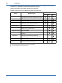
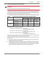
The types of equipment described in this manual and the contents for each one are as shown below.
Types of Equipment Described in This Manual and Contents for Each One
Items Described in the Manual
Model
Product Name
Specifications
Installation
Operation
Maintenance
CMPL
ZS8D-L
General-purpose detector
ZS8D-H
High-temperature detector
ZS8C
Converter
ZS8P-H
Probe adaptor
ZA8F
Flow setting unit
—
Ejector assembly
(Part No.: K9292VA/VB/WA/WB)
—
Calibration gas unit case (Part No.: E7044KF)
CAUTION
There are two types of general-purpose detectors: one which vents to the outside of a furnace the
mixed gases of a sample gas suctioned in by the ejector and ejector air, and another which returns
mixed gases to the furnace. High-temperature detectors all vent to the outside of a furnace. Vent the
mixed gas of a sample gas and ejector air to a place where no safety problems will occur (the venting
flowrate should be 40 to 50 l/min). A general-purpose detectors may be a “return to the furnace” type.
A return pipe is provided as standard. However, be cautious in returning gas to a furnace because air
is blown into the furnace. The normal flow rate of Netwrining gas is approximately 3 l/min to 5 l/min.
IM 11M7A3-01E
iv
<PREFACE>
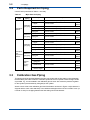
This manual takes the following configuration. A brief description of each chapter and the chapters to
be referred to for installation, operation and maintenance are given.
Chapter configuration of the manual and items to be referred to.
Chapter Configuration of This Manual and Items to be Referred to
Chapter
Brief description
1. General
System component units for the EXA OXY zirconia
oxygen analyzer and system configuration are shown.
2. Installation
Installation procedures for each unit are described.
3. Piping
Piping procedures are explained for four standard
system configurations.
4. Wiring
Wiring procedures are given for each system, such as
power supply wiring, output signal wiring, etc.
5.Components and
their functions
Names and major functions of components of main
units in the manual are illustrated.
6. Operation
Basic procedures are presented to put the EXA OXY
analyzer into the operation status.
7.Operating keys and
display of converter
Converter key operations and items related to the
display are detailed.
8. Calibration
Calibration procedures carried out as necessary are
described.
9.Inspection and
maintenance
Inspection items to maintain the EXA OXY analyzer
performance and procedures for replacing
deteriorated parts and components are described.
10.Troubleshooting
Countermeasures when the system fails and/or
disposition for failure are shown.
Customer maintenance Parts that can be freely replaced by the user if
parts list
damaged are illustrated for each unit.
: Thoroughly read the instructions and do work after fully understanding the contents.
: Before actual work, first read the description or refer to it if necessary.
: It is recommended that you read the description.
IM 11M7A3-01E
For reference to
Installation
Operation
Maintenance
<PREFACE>
Precautions for Flameproof Instruments
1. General
Instruments with Flameproof construction (hereafter referred to as flameproof instruments) are tested
and certified by the public authority in accordance with the Labor Safety and Health Laws of Japan.
A certified instrument is provided with a certification label and a nameplate that states specifications
required for explosion protection performance. All installations of certified instruments should be
executed in compliance with the nameplate specifications.
For details, see USERS' GUIDELINES for Electrical Installation for Explosive Gas Atmospheres
in General Industry, issued by the Research Institute of Industrial Safety of the Ministry of Labor in
Japan, 1994.
2. Flameproof Instruments
Instruments that can be termed "flameproof" must satisfy the following conditions.
They must have been tested and certified by an official body in accordance with the Industrial Safety
and Health Act and must carry a certification label on them.
They must be used in accordance with the specifications stated on the nameplate.
The following operating conditions must be observed.
(1) ZS8D Detector
(a) Before opening the cover, remove power and allow the detector to stand at least 40
minutes.
(b) When the ambient temperature of the detector exceeds 30ºC, use wire resistant to 70ºC or
greater for external wiring.
(c) The detector cannot be used except in mixed gases composing air or mixed gas with
oxygen concentration lower than air, or combustible gas or vapor.
(2) Converter
(a) Before opening the cover, remove power and make sure of non-hazardous atmospheres.
The warning added on page i must be observed.
(b) When the ambient temperature of the converter exceeds 50ºC, use wire resistant to 70ºC
or greater for external wiring.
3. Flameproof Instrument Installation
(1) Installation Area
Flameproof instruments may be installed in hazardous areas where the specified gases are present.
They should not be installed in Division 0 areas.
Note: Hazardous areas are distinguished based on the frequency and duration of the occasions when explosive atmospheres are
encountered (IEC standard 79-10 classification of hazardous areas).
Areas where explosive atmospheres are continuously present or persist for long periods are classified as Division 0.
Areas where there is a risk that an explosive atmosphere will be encountered during normal operation of the equipment and
facilities are classified as Division 1.
Areas where there is no risk that an explosive atmosphere will be encountered during normal operation of the equipment and
facilities, and where an explosive atmosphere will persist for only a short period even if encountered, are classified as Division 2.
(2) Environmental Conditions
The standard environmental condition for flameproof instrument installation is an ambient temperature
range of −20 to 40°C. If the equipment is installed where there is a risk that it may be exposed to
radiant heat from plant equipment, direct sunlight, etc., take steps to heat-insulate the equipment.
IM 11M7A3-01E
vi
<PREFACE>
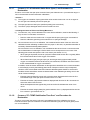
4. External Wiring for Flameproof Instruments
External wiring for flameproof instruments must employ cable wiring. Securely ground all non-live
metal parts. For details, see USERS’ GUIDELINES for Electrical Installation for Explosive Gas
Atmospheres in General Industry, issued by the Research Institute of Industrial Safety of the Ministry
of Labor in Japan, 1994.
It is recommended to use cable glands for wiring.
• Use PVC insulated and sheathed control cable CVV (JIS C 3401) or equivalent. Where
protection from external physical damage is required, the cable must be enclosed in steel
conduit.
• Connections between such cables, or between such cables and wiring routed through
flameproof metal conduit, must be enclosed in a flameproof junction box per item (2), to prevent
any explosive gases from entering and flame fronts from moving in cables.
• For instruments in which cables are to be brought in through flameproof packings, use the
flameproof packing glands specified for use with the instruments and select the flameproof
packings whose internal diameters are appropriate for the cable external diameters.
• If a flameproof packing gland is used, screw it into the connection port so that a minimum
of five threads are fully engaged, and fasten securely with a lock nut. It is mandatory that a
nonhardening sealant be applied to the threads for waterproofing.
• The flameproof gland packing should be securely tightened to prevent the passage of explosive
gases or flame fronts.
5. Maintenance of Flameproof Instruments
When opening the cover for maintenance, the warning added on page i must be observed.
(1) Maintenance with Power ON
Maintenance of flameproof instruments with power on should be avoided unless there is no
alternative. However, if maintenance with power on cannot be avoided, a gas detector should first be
used to verify that an explosive atmosphere is not present, before the instrument cover is opened. If
it is not possible to verify that explosive gases are not present, the scope of maintenance should be
limited to the following:
(a) Visual inspection
Visually inspect the flameproof instrument, metal conduit, cables, etc., for physical damage
and corrosion, and other mechanical and structural defects.
(b) Key operation
Adjustment should be made only to the extent that it can be done from the outside without
opening the instrument cover. Great care must be taken not to cause mechanical sparks
with tools.
IM 11M7A3-01E
vii
<PREFACE>
(2) Repairs
If a flameproof instrument requires repair, turn off the power, and carry the instrument to a
nonhazardous area. Observe the following points during repair:
(a) Make only such electrical and mechanical repairs as will restore the equipment to its
original condition. In the case of a Flameproof instrument, mechanical aspects such as
the gaps and path lengths of joints and mating surfaces, and mechanical strength of
enclosures, are critical factors in explosion protection. Exercise great care not to damage
the joints and mating surfaces, and to protect enclosures from shock.
(b) If damage is incurred by any area of a part critical to the maintenance of flameproof
performance (for example, threads, joints or mating surfaces, inspection windows,
connecting section between transmitter and terminal box, shrouds or clamps, external
wiring connection ports, etc.), contact Yokogawa.
Note: Never rethread a threaded connection or refinish or touch up the finish on a joint or mating surface. Doing so is
extremely dangerous, as the flameproof explosion protection will be compromised.
(c) Unless otherwise specified, electrical circuits and mechanisms inside the enclosure may
be repaired by component replacement, as this will not directly affect flameproof explosion
protection (however, the instrument should always be restored to its original condition).
Only Yokogawa-specified parts should be used for repair.
(d) Before returning a repaired instrument to service, always reinspect all parts necessary for
the preservation of flameproof explosion protection. Verify that all screws, bolts, nuts, and
threaded connections are properly tightened.
(3) Prohibition of Specification Changes and Modifications
Users are prohibited from making any modifications to specifications or physical configuration, such
as adding or changing the configuration of external wiring ports.
6. Flameproof Packing Gland Selection
CAUTION
The flameproof packing glands used at the external wiring connection ports of Flameproof instruments
conforming to IEC standards are certified in combination with the flameproof instruments. Therefore,
only those flameproof packing glands specified by Yokogawa should be used.
IM 11M7A3-01E
viii
<PREFACE>
After-Sales Warranty
n Do not modify the product.
n Yokogawa warrants the product for the period stated in the pre-purchase
quotation. Yokogawa shall conduct defined warranty service based on its
standard. When the customer site is located outside of the service area, a fee
for dispatching the maintenance engineer will be charged to the customer.
n During the warranty period, for repair under warranty carry or send the
product to the local sales representative or service office. Yokogawa will
replace or repair any damaged parts and return the product to you.
• Before returning a product for repair under warranty, provide us with the model name and serial
number and a description of the problem. Any diagrams or data explaining the problem would
also be appreciated.
• If we replace the product with a new one, we won't provide you with a repair report.
n In the following cases, customer will be charged repair fee regardless of
warranty period.
• Failure of components which are out of scope of warranty stated in instruction manual.
• Failure of components which are out of scope of warranty stated in instruction manual.
• Failure caused by usage of software, hardware or auxiliary equipment, which Yokogawa did not
supply.
• Failure due to improper or insufficient maintenance by user.
• Failure due to misoperation, misuse or modification which Yokogawa does not authorize.
• Failure due to power supply (voltage, frequency) being outside specifications or abnormal.
• Failure caused by any usage out of scope of recommended usage.
• Any damage from fire, earthquake, a storm and flood, lightning, disturbance, riot, warfare,
radiation, and other natural changes.
n Yokogawa does not warrant conformance with the specific application at the
user site. Yokogawa will not bear direct/indirect responsibility for damage due
to a specific application.
n Yokogawa will not bear responsibility when the user configures the product
into systems or resells the product.
n Maintenance service and supplying repair parts will be covered for five years
after the production ends. For repair this product, please contact the nearest
sales office described in this instruction manual.
IM 11M7A3-01E
<CONTENTS>
Model ZS8
Flameproof
Zirconia Oxygen Analyzer
IM 11M7A3-01E 3rd Edition
CONTENTS
PREFACE...................................................................................................................i
Introduction.........................................................................................................iii
Precautions for Flameproof Instruments.........................................................v
After-Sales Warranty........................................................................................viii
1.
General....................................................................................................... 1-1
1.1
System Configuration....................................................................................... 1-1
1.1.1
1.2
2.
Examples of System Configuration.................................................... 1-2
Specifications..................................................................................................... 1-6
1.2.1
General Specifications........................................................................ 1-6
1.2.2
Characteristics.................................................................................... 1-7
1.2.3
Flameproof Detector ZS8D................................................................. 1-7
1.2.4
High Temperature Probe Adaptor ZS8P-H....................................... 1-14
1.2.5
Flameproof Converter ZS8C............................................................ 1-16
1.2.6
Options.............................................................................................. 1-20
Installation.................................................................................................. 2-1
2.1
2.2
2.3
Installation of Flameproof General-purpose Detector................................... 2-1
2.1.1
Installation Site.................................................................................... 2-1
2.1.2
Probe Insertion Hole........................................................................... 2-1
2.1.3
Detector Installation............................................................................ 2-2
2.1.4
Reference Air Outlet............................................................................ 2-2
2.1.5
Heat Insulation.................................................................................... 2-3
Installation of Flameproof High-temperature Detector................................. 2-3
2.2.1
Installation Site.................................................................................... 2-3
2.2.2
Probe Insertion Hole........................................................................... 2-3
2.2.3
Detector Installation............................................................................ 2-4
2.2.4
Ejector Installation............................................................................... 2-5
2.2.5
Heat Insulation.................................................................................... 2-6
2.2.6
Blocking Radiant Heat........................................................................ 2-6
Heat Insulation................................................................................................... 2-6
2.3.1
Surface Temperature of Detector....................................................... 2-6
2.3.2
Portions Requiring Heat Insulation and Temperature to be
Maintained.......................................................................................... 2-6
2.3.3
Methods to Change the Surface Temperature................................... 2-7
IM 11M7A3-01E
ii
<CONTENTS>
2.4
2.5
2.6
3.
4.
Fitting a Thermal Insulating Jacket (Option)....................................... 2-8
2.3.5
Heating and Insulation Range when Not Using a Heat-Insulating
Jacket ............................................................................................... 2-15
Installation of Converter.................................................................................. 2-18
2.4.1
Installation Site.................................................................................. 2-18
2.4.2
Converter Mounting.......................................................................... 2-18
Installation of Flow Setting Unit..................................................................... 2-19
2.5.1
Installation Site.................................................................................. 2-19
2.5.2
Flow Setting Unit Mounting .............................................................. 2-20
Installation of Calibration Gas Unit Case...................................................... 2-21
2.6.1
Installation Site.................................................................................. 2-21
2.6.2
Mounting........................................................................................... 2-21
Piping.......................................................................................................... 3-1
3.1
System................................................................................................................ 3-1
3.2
Parts Required for Piping.................................................................................. 3-2
3.3
Calibration Gas Piping...................................................................................... 3-2
3.4
Reference Gas Piping........................................................................................ 3-3
3.5
Piping to Probe Adaptor.................................................................................... 3-3
3.6
Purge Gas Piping............................................................................................... 3-4
3.6.1
Piping for Air Purge in Converter........................................................ 3-4
3.6.2
Air Supply for Air Purging.................................................................... 3-4
Wiring.......................................................................................................... 4-1
4.1
4.2
4.3
4.4 IM 11M7A3-01E
2.3.4
Safety Precaution for External Wiring............................................................. 4-1
4.1.1
Wiring Precautions.............................................................................. 4-1
4.1.2
Care During Wiring............................................................................. 4-2
4.1.3
Cables................................................................................................. 4-4
4.1.4
Mounting of Cable Gland.................................................................... 4-5
Wiring for Detector Signal................................................................................. 4-6
4.2.1
Cable Specifications........................................................................... 4-6
4.2.2
Connection to Detector....................................................................... 4-6
4.2.3
Connection to Converter..................................................................... 4-6
Wiring for Detector Heater Power.................................................................... 4-7
4.3.1
Wiring for Sensor Heater Power (In the case of steam heater).......... 4-7
4.3.2
Wiring for Detector Heater Power (In the case of electric heater)...... 4-7
4.3.3
Cable Specifications........................................................................... 4-7
4.3.4
Connection to Detector....................................................................... 4-7
4.3.5
Connection to Converter..................................................................... 4-7
Wiring for Analog Output.................................................................................. 4-8
4.4.1
Cable Specifications........................................................................... 4-8
4.4.2
Wiring Procedure................................................................................ 4-8
iii
<CONTENTS>
4.5 4.6
4.7
4.8
4.9
5.
Power Wiring....................................................................................... 4-9
4.5.2
Ground Wiring..................................................................................... 4-9
Digital Communication Wiring....................................................................... 4-12
4.6.1
Wiring of RS-422-A Communication Cable...................................... 4-12
4.6.2
ZS8C Converter Communication (RS-422-A) Specifications ......... 4-13
Contact Output Wiring..................................................................................... 4-21
4.7.1
Cable Specifications......................................................................... 4-21
4.7.2
Wiring Procedure.............................................................................. 4-21
Contact Input Wiring........................................................................................ 4-21
4.8.1
Cable Specifications......................................................................... 4-22
4.8.2
Wiring Procedure.............................................................................. 4-22
Wiring for Solenoid Valve................................................................................ 4-22
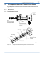
Detector............................................................................................................... 5-1
5.1.1
General-purpose Detector.................................................................. 5-1
5.1.2
High-temperature Detector
(with a high-temperature probe adaptor)............................................ 5-2
5.2
Converter............................................................................................................ 5-3
5.3 Flow Setting Unit................................................................................................ 5-4
Operation.................................................................................................... 6-1
6.1
6.2
7.
4.5.1
Components and Their Functions........................................................... 5-1
5.1
6.
Power and Ground Wiring................................................................................ 4-9
Startup................................................................................................................. 6-1
6.1.1
Inspection of Piping and Wiring Conditions........................................ 6-1
6.1.2
Checking the Heat Insulation Conditions............................................ 6-1
6.1.3
Checking of Set Valves....................................................................... 6-2
6.1.4
Supplying Power to Converter............................................................ 6-2
6.1.5
During Warming-up............................................................................. 6-2
6.1.6
Data Setting (To set data, enter the password “16”)........................... 6-2
6.1.7
Set of Relay Contacts for Contact Output......................................... 6-17
6.1.8
Supplying Pressure to Ejector.......................................................... 6-18
6.1.9
Calibration......................................................................................... 6-19
6.1.10
Checking Functional Operations...................................................... 6-20
Stationary Operation....................................................................................... 6-20
6.2.1
Collection of Control Data................................................................. 6-20
6.2.2
Troubleshooting................................................................................ 6-20
6.2.3
Checking Operating Conditions........................................................ 6-21
6.2.4
Stopping and Restarting Operations ............................................... 6-22
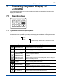
Operating Keys and Display of Converter.............................................. 7-1
7.1
Operating Keys.................................................................................................. 7-1
7.1.1
Types and Functions of Operating Keys............................................. 7-1
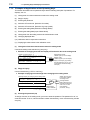
7.1.2
Examples of Applications of the Operating Keys................................ 7-2
IM 11M7A3-01E
iv
<CONTENTS>
7.2
8.
8.2
8.3
9.2
7.2.2
Data Display........................................................................................ 7-6
7.2.3
Message Display................................................................................ 7-6
General................................................................................................................ 8-1
8.1.1
Principles of Zirconia Oxygen Analyzer.............................................. 8-1
8.1.2
Calibration Gas................................................................................... 8-2
8.1.3
Compensation..................................................................................... 8-2
8.1.4
Characteristic Data from a Sensor Measured During Calibration...... 8-3
Calibration Procedures..................................................................................... 8-4
8.2.1
Operation Flowchart of Semi-Automatic and Automatic
Calibrations......................................................................................... 8-4
8.2.2
Operation Flowchart........................................................................... 8-5
Methods of Operating Valves in the ZA8F Flow Setting Unit........................ 8-7
8.3.1
Preparation before Calibration............................................................ 8-7
8.3.2
Operating the Span Gas Flow Setting Valve...................................... 8-7
8.3.3
Operating the Zero Gas Flow Setting Valve....................................... 8-7
8.3.4
Treatment after Calibration................................................................. 8-7
Inspection and Maintenance of the Detector.................................................. 9-1
9.1.1
Precautions for Inspecting the Detector............................................. 9-1
9.1.2
Checking the Flow of Sucked Sample Gases.................................... 9-1
9.1.3
Calibration of Indication...................................................................... 9-2
9.1.4
Checking the Flow Setting Unit During Normal Operation................. 9-2
9.1.5
Cleaning the Sensor Assembly........................................................... 9-2
9.1.6
Cleaning the Calibration Gas Tube..................................................... 9-4
9.1.7
Replacing the Sensor Assembly......................................................... 9-4
9.1.8
Cleaning the High-Temperature Probe Adapter................................. 9-6
Inspection and Maintenance of the Converter............................................... 9-7
9.2.1
Replacing Fuses................................................................................. 9-7
9.2.2
Replacing the Message Display Unit.................................................. 9-8
Troubleshooting...................................................................................... 10-1
10.1
IM 11M7A3-01E
Status Display..................................................................................... 7-6
Inspection and Maintenance.................................................................... 9-1
9.1
10.
7.2.1
Calibration.................................................................................................. 8-1
8.1
9.
Readout Displays............................................................................................... 7-6
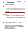
Disposal When an Error Code Is Displayed.................................................. 10-1
10.1.1
Types of Error Codes ....................................................................... 10-1
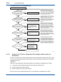
10.1.2
Causes of “E--1 Sensor (Cell) Failure” and Procedure for
Restoration........................................................................................ 10-2
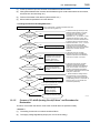
10.1.3
Causes of “E--2 Sensor Temperature Error (Low)” and
Procedure for Restoration................................................................. 10-3
10.1.4
Causes of “E--3 Sensor Temperature Error (High)” and
Procedure for Restoration................................................................. 10-4
<CONTENTS>
10.2
10.3
10.1.5
Causes of “E--4 A/D (Analog Circuit) Failure” and
Procedure for Restoration................................................................ 10-5
10.1.6
Causes of “E--5 Calibration Value Error (Zero)” and
Procedure for Restoration...................................................................... 10-6
10.1.7
Causes of “E--6 Calibration Value Error (Span)” and
Procedure for Restoration................................................................. 10-7
10.1.8
Causes of “E--7 EMF Stabilization Time Over” and
Procedure for Restoration................................................................. 10-7
10.1.9
Causes of “E--8 ROM and RAM Failure” and
Procedure for Restoration................................................................. 10-8
10.1.10
Causes of Display Disappearance (Data Display) and
Procedure for Restoration................................................................. 10-8
Where the Output Response Is Too Slow..................................................... 10-9
10.2.1
Checking the Main Ejector for Clogging........................................... 10-9
10.2.2
Checking the Auxiliary Ejector for Clogging...................................... 10-9
10.2.3
Checking the Tip Filter (SiC) for Clogging........................................ 10-9
10.2.4
Others............................................................................................... 10-9
Measures When Measured Value Shows an Error....................................... 10-9
10.3.1
Measured Value Higher Than True Value.......................................10-10
10.3.2
Measured Value Lower Than True Value....................................... 10-11
10.3.3
Measured Value Sometimes Show Abnormal Values.................... 10-11
Customer Maintenance Parts List...........................................CMPL 11M7A3-01E
Customer Maintenance Parts List...........................................CMPL 11M7A3-03E
Customer Maintenance Parts List...........................................CMPL 11M7A3-04E
Customer Maintenance Parts List...........................................CMPL 11M7A3-11E
Revision Record........................................................................................................i
IM 11M7A3-01E
Blank Page
1.
<1. General>
1-1
General
The ZS8 flameproof zirconia oxygen analyzer can be used for monitoring and controlling oxygen
concentrations in combustion gases in heating furnaces or boilers in petroleum refining, petrochemical
and city gas production industries.
The analyzer mainly consists of a detector and a converter. The ZS8 flameproof detector includes
general-purpose detectors that can be used for measuring gases at up to 800°C and hightemperature detectors that can be applied to measuring gases at 800°C or more. These detectors
are both direct-insertion detector. This allows the detectors to be mounted on flue walls or the like
to measure internal gases directly. The converter has good operability and is provided with many
functions (measurement and computing functions and maintenance functions such as self-diagnosis)
as standard. In addition, digital communication functions can be added. For calibration, one-touch
calibration can be performed with key operation of the converter by using the ZA8F flow setting unit
and making zero and span gases flow. As stated above, since the ZS8 flameproof zirconia oxygen
analyzer is provided with a number of functions and many auxiliary units, the optimum system can be
constructed by selecting the units matching an application.
1.1
System Configuration
The ZS8 oxygen analyzer is composed of the following units:
(1) ZS8D flameproof detector
(2) ZS8C flameproof converter
(3) ZA8F flow setting unit
(4) Calibration gas unit (consists of a zero-gas cylinder, pressure regulator, and case assembly).
However, note that the units to be used differ depending on the specifications.
IM 11M7A3-01E
1-2
<1. General>
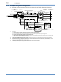
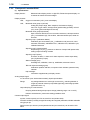
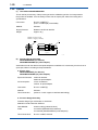
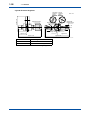
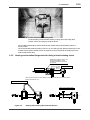
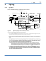
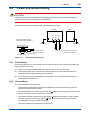
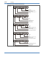
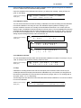
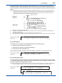
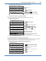
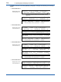
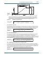
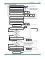
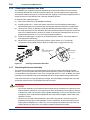
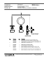
1.1.1 Examples of System Configuration
(1) Example of Heat Insulation with Electric Heater (for the ZS8D-L flameproof detector)
ZS8D
Flameproof detector Conduit *1
*2
Wiring for heat insulation
Provided by heaters
Stop valve
Ejector air
Interior of
furnace
Hazardous
location
Pressure gauge 20kPa *4
ZS8C
Flameproof converter
Air set
4 to 20mA DC
output
P
Detector output wiring
(1.25mm2 or more, 8-wire shielded cable)
MEAS
MAINT
ALM
FAIL
DATA
vol%O
Contact output
Detector heater power wiring
(2mm2 or more, 4-wire shielded cable)
Heat insulation
*2
Check valve
(K9292DN,
K9292DS) Reference-gas flow meter
300 ml/min ±20%
Reference
gas
Needle valve
Needle valve
Flow setting unit (ZA8F)
*2:
*3:
*4:
IM 11M7A3-01E
100V, 115V,
220V, 240V AC
Air set (G7003XF, K9473XK)
P
Calibration-gas
flow meter
600 ml/min ±10%
*1:
Contact input
Instrument
air
Needle valve
Calibration
gas *3
Non-hazardous
location
Calibration-gas unit
P
P
Calibration-gas
pressure
regulator
(G7013XF,
G7014XF)
Calibration-gas unit
P
P
Calibration-gas
pressure
regulator
Zero-gas cylinder
(G7001ZC)
Span-gas
cylinder
F1.1E.ai
Conduits
1)When installing conduits, use flexible conduits so that the probe removed.
2)Use a shielded cable for the signal cable and ground the shield together with the probe ground.
3)Provide separate conduits for the signal and heater lines.
4)The maximum outside diameter of the cable suited for the cable gland used for the instrument is 13.5mm (in case
that the thread at the conduit side is G3/4)
The probe material SUS310S or SiC should be selected according to the specified measurement gas temperature
(SUS310S: 0 to 800°C, SiC: 800 to 1400°C).
For the zirconia oxygen analyzer, 100% nitrogen cannot be used as the zero gas. Generally, approximately a 1 vol%
oxygen (nitrogen gas balance) mixture is used.
The setting of the ejector supply air pressure depends on the furnace pressure.
1-3
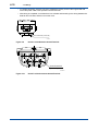
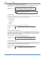
<1. General>
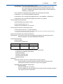
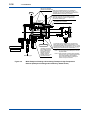
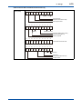
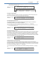
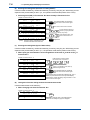
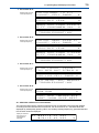
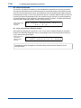
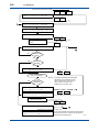
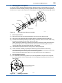
(2) Example of Heat Insulation with Electric Heater (for the ZS8D-H flameproof hightemperature detector)
Pressure gauge 98kPa *4
Stop valve Air set
P
Auxiliary ejector air
Conduit *1
Wiring for heat insulation
Provided by heaters
Heat insulation
Pressure gauge 20kPa *4
Stop valve Air set
Main ejector air
Check valve
(K9292DN, Reference-gas
K9292DS)
flow meter
300 ml/min ±20%
Calibration
gas *3
*2:
*3:
*4:
MEAS
MAINT
ALM
FAIL
DATA
vol%O
Contact output
Contact input
100V, 115V,
220V, 240V AC
(G7003XF, K9473XK)
Air set
P
Instrument
air
Needle valve
Needle valve
Calibration-gas
flow meter
600 ml/min ±10% Needle valve
Flow setting unit (ZA8F)
*1:
Hazardous location
4 to 20mA
DC output
Detector heater power wiring
(2mm2 or more, 4-wire shielded cable)
Reference
gas
Non-hazardous
location
P
Detector output wiring
(1.25mm2 or more, 8-wire shielded cable)
High
temperature
probe
adaptor *2
Interior of
furnace
ZS8C
Flameproof
converter
Calibration-gas unit
P
P
Calibration-gas
pressure
regulator
(G7013XF,
G7014XF)
Calibration-gas unit
P
P
Calibration-gas
pressure
regulator
Zero-gas cylinder
(G7001ZC)
Span-gas
cylinder
F1.2E.ai
Conduits
1)When installing conduits, use flexible conduits so that the probe removed.
2)Use a shielded cable for the signal cable and ground the shield together with the probe ground.
3)Provide separate conduits for the signal and heater lines.
4)The maximum outside diameter of the cable suited for the cable gland used for the instrument is 13.5mm (in case
that the thread at the conduit side is G3/4)
The probe material SUS310S or SiC should be selected according to the specified measurement gas temperature
(SUS310S: 0 to 800°C, SiC: 800 to 1400°C).
For the zirconia oxygen analyzer, 100% nitrogen cannot be used as the zero gas. Generally, approximately a 1 vol%
oxygen (nitrogen gas balance) mixture is used.
The setting of the ejector supply air pressure depends on the furnace pressure.
IM 11M7A3-01E
1-4
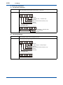
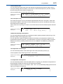
<1. General>
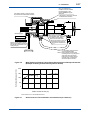
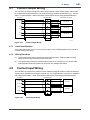
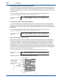
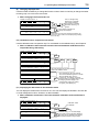
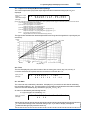
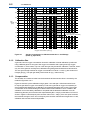
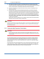
(3) Example of Steam Trace Heat Insulation (for the ZS8D-L flameproof detector)
ZS8D
Flameproof detector Conduit *1
*2
Steam outlet
Steam inlet
Ejector air
Interior of
furnace
Heat insulation
ZS8C
Flameproof
converter
Pressure gauge 20kPa *4
Stop valve
Air set
4 to 20mA
DC output
P
Detector output wiring
(l.25mm2 or more, 6-wire shielded cable)
MEAS
MAINT
ALM
FAIL
Reference
gas
Calibration
gas *3
Needle valve
Air set
(G7003XF, K9473XK)
Instrument
Calibration-gas unit
air
P
Calibration-gas unit
P
P
*3:
*4:
IM 11M7A3-01E
P
Calibration-gas
pressure regulator
Calibration-gas
pressure regulator
Flow setting unit (ZA8F) (G7013XF,
G7014XF)
*2:
Contact output
100V, 115V,
220V, 240V AC
Needle valve
Calibration-gas
flow meter
600 ml/min ±10%
vol%O
Contact input
P
Needle valve
*1:
DATA
Detector heater power wiring
(2mm2 or more, 2-wire shielded cable)
Check valve
(K9292DN,
K9292DS) Reference-gas
flow meter
300 ml/min ±20%
Hazardous Non-hazardous
location
location
Zero-gas cylinder
(G7001ZC)
Span-gas
cylinder
F1.3E.ai
Conduits
1)When installing conduits, use flexible conduits so that the probe removed.
2)Use a shielded cable for the signal cable and ground the shield together with the probe ground.
3)Provide separate conduits for the signal and heater lines.
4)The maximum outside diameter of the cable suited for the cable gland used for the instrument is 13.5mm (in case
that the thread at the conduit side is G3/4)
The probe material SUS310S or SiC should be selected according to the specified measurement gas temperature
(SUS310S: 0 to 800°C, SiC: 800 to 1400°C).
Detectors need sufficient heat insulation. For combustion including ion components, ensure heat insulation greater
than dew point of sulfuric acid (about 160°C). In this case, the steam pressure should be greater than 800kPa. If such
pressure cannot be obtained, use heat insulation with an electric heater.
For gas combustion where ion components are not included, heat insulation at about 130°C is sufficient even at a steam
pressure of 200 to 300kPa.
For the zirconia oxygen analyzer, 100% nitrogen cannot be used as the zero gas. Generally, approximately a 1 vol%
oxygen (nitrogen gas balance) mixture is used.
The setting of the ejector supply air pressure depends on the furnace pressure.
1-5
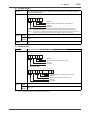
<1. General>
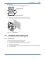
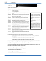
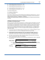
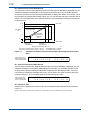
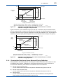
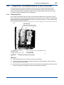
(4) Example of Steam Trace Heat Insulation (for the ZS8D-H flameproof detector)
Conduit *1
Pressure gauge 98kPa *4
Auxiliary ejector air
Steam outlet
Steam inlet
Heat
insulation
Stop valve Air set
P
Main ejector air
Stop valve Air set
Check valve
(K9292DN, Reference-gas
K9292DS) flow meter
300 ml/min ±20%
Reference
gas
Calibration
gas *3
Flow setting unit (ZA8F)
*4:
DATA
vol%O
Contact output
Contact input
100V, 115V,
220V, 240V AC
Air set (G7003XF, K9473XK)
Instrument
air
Needle valve
Needle valve
*3:
MEAS
MAINT
ALM
FAIL
P
Calibration-gas Needle valve
flow meter
600 ml/min ±10%
Non-hazardous
location
4 to 20mA
DC output
Detector heater power wiring
(2mm2 or more, 2-wire shielded cable)
Interior of
furnace
*2:
Hazardous
location
P
Detector output wiring
(1.25mm2 or more, 6-wire shielded cable)
High
temperature
probe
adaptor *2
*1:
ZS8C
Flameproof
converter
Pressure gauge 20kPa *4
Calibration-gas unit
Calibration-gas unit
P
P
Calibration-gas
pressure regulator
(G7013XF,
G7014XF)
Zero-gas
cylinder
(G7001ZC)
P
P
Calibration-gas
pressure
regulator
Span-gas
cylinder
F1.4E.ai
Conduits
1)When installing conduits, use flexible conduits so that the probe removed.
2)Use a shielded cable for the signal cable and ground the shield together with the probe ground.
3)Provide separate conduits for the signal and heater lines.
4)The maximum outside diameter of the cable suited for the cable gland used for the instrument is 13.5mm (in case
that the thread at the conduit side is G3/4)
The probe material SUS310S or SiC should be selected according to the specified measurement gas temperature
(SUS310S: 0 to 800°C, SiC: 800 to 1400°C).
Detectors need sufficient heat insulation. For combustion including ion components, ensure heat insulation greater
than dew point of sulfuric acid (about 160°C). In this case, the steam pressure should be greater than 800kPa. If such
pressure cannot be obtained, use heat insulation with an electric heater.
For gas combustion where ion components are not included, heat insulation at about 130°C is sufficient even at a steam
pressure of 200 to 300kPa.
For the zirconia oxygen analyzer, 100% nitrogen cannot be used as the zero gas. Generally, approximately a 1 vol%
oxygen (nitrogen gas balance) mixture is used.
The setting of the ejector supply air pressure depends on the furnace pressure.
IM 11M7A3-01E
1-6
<1. General>
1.2
Specifications
1.2.1 General Specifications
Measurement Target:
Oxygen concentration in combustion exhaust gases and mixed gases
(excluding flammable gases)
Measurement System:
Zirconia system
Flameproof Construction:
Detector;
Exd II BT3X (Max. surface temperature of 200°C)
Converter;
Exd II BT6 (Max. surface temperature of 85°C)
Used condition of Flameproof
Converter:
(a) Before opening the cover, remove power and make sure of non-hazardous
atmospheres.
(b)When the ambient temperature of the converter exceeds 50°C, use wire resistant to
70°C or greater for external wiring.
Detector:
(a)Before opening the cover, remove power and allow the detector to stand at least 40
minutes.
(b)When the ambient temperature of the detector exceeds 30°C, use wire resistant to 70°C
or greater for external wiring.
(c)The detector cannot be used except in mixed gases composing air or mixed gas with
oxygen concentration lower than air, or combustible gas or vapor.
Measurement Range:
0 to 100 vol%O2 (3-digit digital display)
Display;
Output;
0 to 5 vol%O2 to 0 to 25 vol%O2
Although the measuring range can be set up to 0 to 25 vol%O2, a sample gas with the oxygen
concentration of over 21 vol%O2 cannot be measured in terms of the flameproof standard.
Warm-up Time:
Approx. 30 minutes
Maximum Distance Between Probe and Converter:
Conductor two-way resistance must be 10Ω or less
(300 m or less with 1.25 mm2 conductors)
Power Supply:
100, 115, 220, 240 V AC +10%, −15% 50/60 Hz
Power Consumption:
Analyzer;
80 VA for ordinary use, maximum of 270 VA
Electric heaters providing heat insulation;
approximately 200 VA for ordinary use, maximum of approximately 400 VA
IM 11M7A3-01E
1-7
<1. General>
1.2.2 Characteristics
Repeatability:
± 0.5% of span (0 to 5 vol%O2 or more and up to 0 to 25 vol%O2 range)
Linearity:
± 1% of span(0 to 5 vol%O2 or more and up to 0 to 25 vol%O2 range)
[Sample gas pressure: within + 4.9 kPa ]
The following conditions must be satisfied.
Use oxygen of known concentration (with in the measuring range) as the
zero and span calibration gases.
Excluding standard gas tolerance
Excluding the cases where the reference air is by natural convection.
Drift: ± 2.0% of span/month (both zero and span)
Response Time:90% response within 5 seconds (measured when gas is fed through the
calibration gas inlet and the analog output signal begins to change)
1.2.3 Flameproof Detector ZS8D
(1) Specifications
Sampling Method:
Air ejector method
Ejector air; Supply pressure 20 kPa, flow rate at 4 l/min or less
At atmospheric pressures inside the furnace
(As sample-gas exhaust methods, “recirculate in furnace” and “discharge
outside furnace” are available. Specify the method using our model code
according to specifications when ordered.
For high-temperature detector, only “discharge outside furnace” is available.)
Sample Gas Temperature:
ZS8D-L; 0 to 800°C (general-purpose detector)
(Probe material: SUS310S)
ZS8D-H;
800 to 1400°C (high-temperature detector)
(Probe material: SiC)
For this type, probe adaptor ZS8P-H is required. (The ZS8D-H hightemperature detector can be selected if a general-purpose detector cannot
be installed owing to limited installation space.)
Sample Gas Pressure: −5 to 5 kPa for the ZS8D-L general-purpose detector
−1.5 to 5 kPa for the ZS8D-H high-temperature detector
Gas Flow Velocity:
30 m/s or less
Dust Amount: 500 mg/Nm3 or less
Heat Insulation: (Select either heat insulation provided by electric heaters or by steam.)
Heat insulation provided by steam
Pressure: Normal 800 kPa, maximum 1 MPa
At temperatures above the dew point of sulfuric acid (below 160°C) and for
gas combustion, there are no sulfuric components, so heat insulation can be
attained at a steam pressure of 200 to 300 kPa. Specify when heavy oil or
heavy oil and gas fuel is used.
IM 11M7A3-01E
1-8
<1. General>
Heat insulation provided by electric heaters
Specify only when gas fuel is used.
Power consumption;200 VA for ordinary use,
maximum of 400 VA;
Temperature: 130°C (Gas fuel)
Reference Gas:
Instrument air 300 ml/min ± 20%
Calibration Gas: Instrument air and standard gas 600 ml/min ± 10%.
Insertion Length:
0.5, 0.7, 1.0, 1.5 m
Surface Temperature:
200°C or less
Material in Contact with Gas:
Probe SUS310S (or SUS304), Zirconia, SUS304 (flange), SUS316 (tube)
Installation: Flange mounting
Probe mounting angle
• ZS8D-L;For SUS310S, between the horizontal and vertically down
positions
• ZS8D-H;For SUS310S, between the horizontal and vertically down
positions
For SiC: Vertically down (within ± 5°)
Joint; Rc1/4 or 1/4NPT (F)
Flange:
• ZS8D-L;JIS 10K-100-FF SUS304, JPI Class 150-4-RF SUS304,
ANSI Class 150-4-RF (no serration) SUS304, DIN PN10DN100-A SUS304.
• ZS8D-H; Case Material: Material in contact with gas; SUS316
Terminal box; Aluminum
Others; SUS304
JIS 5K-65-FF SUS304
Weight: Approx. 10.3 kg with an insertion length of 0.15 m (JIS high-temperature
use).
Approx. 13 to 15 kg with an insertion length of 0.5 m (for JIS/JPI/ANSI/DIN
applications).
Approx. 12 to 15 kg with an insertion length of 0.7 m (for JIS/JPI/ANSI/DLN
applications).
Approx. 14 to 16 kg with an insertion length of 1 m (for JIS/JPI/ANSI/DIN
applications).
Approx. 15 to 17 kg with an insertion length of 1.5 m (for JIS/JPI/ANSI/DIN
applications).
IM 11M7A3-01E
1-9
<1. General>
(2) Model and Suffix Codes
Model
Suffix code
Option
code
Description
ZS8D
-L
-H
· · · · · · · · · · High-temperature detector (800 to 1400°C)
Flameproof
standard
-J
· · · · · · · · · · Exd II BT3X (Maximum surface temperature: 200°C)
Probe material
· · · · · · · · · · General-purpose detector (0 to 800°C)
-A
· · · · · · · · · · SUS310S: Specify for general-purpose detector.
-L
· · · · · · · · · · SUS304: Specify for high-temperature detector.
Insertion length
-010
· · · · · · · · · · 0.1 m: Specify for high-temperature detector.
-050
· · · · · · · · · · 0.5 m: SUS310S (0 to 800°C)
-070
· · · · · · · · · · 0.7 m: SUS310S (0 to 800°C)
-100
· · · · · · · · · · 1.0 m: SUS310S (0 to 800°C)
-150
· · · · · · · · · · 1.5 m: SUS310S (0 to 800°C)
Heat insulation model
-1
· · · · · · · · · · Steam heater
· · · · · · · · · · Electric heater
-2
Power supply (electric
heater providing heat
insulation)
-N
· · · · · · · · · · For heat insulation provided by steam heaters
-3
· · · · · · · · · · 220V AC, 50/60Hz
-4
· · · · · · · · · · 240V AC, 50/60Hz
-5
· · · · · · · · · · 100V AC, 50/60Hz
-8
Exhaust method (*2)
· · · · · · · · · · 115V AC, 50/60Hz
-N
· · · · · · · · · · Specify for high-temperature detector.
-0
· · · · · · · · · · Discharge outside furnace
-1
Flange joint connection
Calibration gas, reference gas,
and ejector inlet joints (*3)
· · · · · · · · · · Recirculate in furnace
-H
· · · · · · · · · · JIS 5K-65-FF, specify for high-temperature detector.
-J
· · · · · · · · · · JIS 10K-100-FF
-K
· · · · · · · · · · JPI Class 150-4-RF
-A
· · · · · · · · · · ANSI Class 150-4-RF
-E
· · · · · · · · · · DIN PN10-DN100-A
J
· · · · · · · · · · Rc1/4
A
· · · · · · · · · · 1/4NPT (F)
Heat insulation jacket (*4)
(*1)
(*2)
(*3)
(*4)
(*1)
/JS
For steam heaters
/JE
For electric heaters
A steam heater [-1] must be specified when heavy oil fuel gas and heavy oil fuel mixture is used or clew point temperature of
exhaust gas is about 130°C. By selecting either -1 or -2, the steam heater or electric heater is installed. For high-temperature
detector, only “discharge outside furnace” is applied.
Select whether to discharge mixed gases (the sample gas sucked in by the ejector plus the ejector air) outside the furnace or to
recirculate them in the furnace. If -1 is selected, a gas-return pipe is provided.
The flameproof detector is equipped with a check valve and auxiliary ejector assembly as standard.
Heat insulation jacket must be ordered. It is essential to use owning hood in where installed in surrounding rain.
(Notes)
(1)
(2)
(3)
Always use the specified external cable lead-in apparatuses given in the table below.
The number of mountable external cable lead-in apparatuses is as follows:
* Cable gland: 1 or 2
As standard, two cable glands (G9601AJ) for the external cable lead-in apparatuses are mounted on the cable inlet ports for
the power supply and output signal. On the remaining port, the blind plug (for heat insulation provided by steam heaters) or
flexible tube (for heat insulation provided by electric heaters) is mounted.
External Cable Lead-in Apparatuses
Name
Part No.
Description
Remarks
CABLE GLAND
G9601AJ
Cable O.D. ø10 to ø13.5
Cable gland
IM 11M7A3-01E
1-10
<1. General>
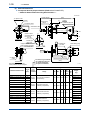
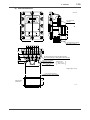
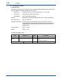
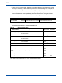
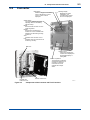
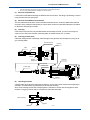
(3) External Dimensions
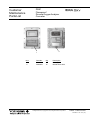
Flameproof General-purpose Detector (ZS8D-L-J-A--1-N--)
— Model for Steam Heater Providing Heat Insulation —
Unit: mm
Insertion length l
<4> Ejector inlet
Ejector
(405)
B
<5>Mounting
flange
<4> Ejector outlet
C
Carborundum filter
<1> Reference gas outlet
A
øB
Approx. 83
C
D
Outlet to return
suctioned gas to
the furnace
(Rc 1/8)
øA
Ejector
B
t
Approx. 93
A
Section A-A
Suction gas
return port
Copper tube for
heat insulation by steam
Section C-C
<3> Steam inlet
<1>Reference
gas inlet
C
With sealing plug
(50) ø150
<2>Calibration gas inlet
<3>Steam
outlet
<1> Reference gas Inlet/Outlet
<2> Calibration gas Inlet
<3> Steam Inlet/Outlet
<4> Ejector Inlet/Outlet
Section B-B
Note that the steam inlet and
outlet positions may be changed.
Model and Suffix Codes
Length
Joint
l
J:Rc1/4
(mm) A:1/4NPT
Check
valve
Two G3/4 openings for wiring
(303)
F1.5E.ai
<5> Flange
Flange
ØA
ØB
C
D
t
t
No
Return
return
type type
Weight
(kg)
ZS8D-L-J-A-050-1-N--J
500
ZS8D-L-J-A-070-1-N--J
700
Approx. 13
ZS8D-L-J-A-100-1-N--J
1000
ZS8D-L-J-A-150-1-N--J
1500
Approx. 15
ZS8D-L-J-A-050-1-N--K
500
Approx. 15
Rc1/4,
1/4NPT
JIS 10K-100-FF SUS304
(or equivalent)
210
175 8-ø19 41
18
18
Approx. 13.5
Approx. 14
ZS8D-L-J-A-070-1-N--K
700
ZS8D-L-J-A-100-1-N--K
1000
ZS8D-L-J-A-150-1-N--K
1500
Approx. 17
ZS8D-L-J-A-050-1-N--A
500
Approx. 15
ZS8D-L-J-A-070-1-N--A
700
ZS8D-L-J-A-100-1-N--A
1000
Rc1/4,
1/4NPT
Rc1/4,
1/4NPT
JPI CLASS 150-4-RF
SUS304 (or equivalent)
ANSI CLASS 150-4-RF
SUS304 (or equivalent)
229 190.5 8-ø19 41
228.6 190.5 8-ø19 41
24
24
24
24
Approx. 15
Approx. 16
Approx. 15
Approx. 16
ZS8D-L-J-A-150-1-N--A
1500
Approx. 17
ZS8D-L-J-A-050-1-N--E
500
Approx. 12
ZS8D-L-J-A-070-1-N--E
ZS8D-L-J-A-100-1-N--E
ZS8D-L-J-A-150-1-N--E
700
1000
1500
IM 11M7A3-01E
Rc1/4,
1/4NPT
DIN PN10-DN100-A
SUS304 (or equivalent)
220
180 8-ø18 41
20
20
Approx. 13
Approx. 13
Approx. 14
1-11
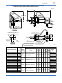
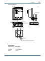
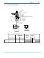
<1. General>
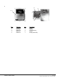
Flameproof General-purpose Detector (ZS8D-L-J-A--2---)
— Model for Electric Heater Providing Heat Insulation —
Unit: mm
Insertion length l
(405)
<3>Ejector
inlet
<3>Ejector
outlet
Ejector
A
Approx. 280
<1>Reference
gas outlet
B
øA
øB
Approx. 83
B
t
Approx. 93
A
Approx.
100
Approx. 250
Section A-A
Outlet to return suctioned gas
to the furnace (Rc 1/8)
<1> Reference gas inlet
50 (ø150)
Suction gas
return port
D
<4>
Mounting flange
C
Check valve
Section B-B
Model and Suffix Codes
ZS8D-L-J-A-050-2---J
<2>Calibration
gas inlet
<1> Reference gas Inlet/Outlet Two G3/4 openings for wiring
<2> Calibration gas Inlet
<3> Ejector Inlet/Outlet
Length
Joint
l
J:Rc1/4
(mm) A:1/4NPT
F1.6E.ai
<4> Flange
Flange
ØA
ØB
C
D
t
t
No
Return
return
type type
500
Weight
(kg)
Approx. 14
ZS8D-L-J-A-070-2---J
700
ZS8D-L-J-A-100-2---J
1000
ZS8D-L-J-A-150-2---J
1500
Approx. 16
ZS8D-L-J-A-050-2---K
500
Approx. 16
ZS8D-L-J-A-070-2---K
700
Rc1/4,
1/4NPT
Rc1/4,
1/4NPT
JIS 10K-100-FF SUS304
(or equivalent)
JPI CLASS 150-4
RFSUS304 (or equivalent)
210
175 8-ø19 41
229 190.5 8-ø19 41
18
24
18
24
Approx. 14.5
Approx. 15
Approx. 16
ZS8D-L-J-A-100-2---K
1000
ZS8D-L-J-A-150-2---K
1500
Approx. 18
Approx. 16
ZS8D-L-J-A-050-2---A
500
ZS8D-L-J-A-070-2---A
700
ZS8D-L-J-A-100-2---A
1000
Rc1/4,
1/4NPT
ANSI CLASS 150-4
RFSUS304 (or equivalent)
228.2 190.5 8-ø19 41
24
24
Approx. 17
Approx. 16
Approx. 17
ZS8D-L-J-A-150-2---A
1500
Approx. 18
ZS8D-L-J-A-050-2---E
500
Approx. 13
ZS8D-L-J-A-070-2---E
ZS8D-L-J-A-100-2---E
ZS8D-L-J-A-150-2---E
700
1000
1500
Rc1/4,
1/4NPT
DIN PN10-DN100-A
SUS304 (or equivalent)
220
180 8-ø18 41
20
20
Approx. 14
Approx. 14
Approx. 15
IM 11M7A3-01E
1-12
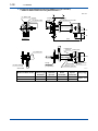
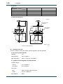
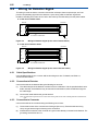
<1. General>
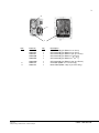
Flameproof High-temperature Detector (ZS8D-H-J-L-010-1-N-N-H)
— Model for Steam Heater Providing Heat Insulation —
B
<4> Ejector inlet
Ejector
Ejector
Insertion A
length l
<4> Ejector outlet
Unit: mm
B
<1>Reference gas outlet
(Approx. 150)
Ø155
Ø130
Approx. 83
14
Approx. 93
A
Section A-A
(405)
<1>Reference
gas inlet Sealing plug
<3> Steam inlet
(Approx. Ø150)
Flange
JIS 5K 65FF
(or equivalent)
<3> Steam outlet
Check valve
<2>Calibration gas inlet
Section B-B
Model and Suffix Codes
F1.7E.ai
<1>
Reference gas
inlet/outlet
<2>
Calibration
gas inlet
<3>
Steam
inlet/outlet
<4>
Ejector
inlet/outlet
ZS8D-H-J-L-010-1-N-N-HJ
Rc1/4
Rc1/4
Rc1/4
Rc1/4
ZS8D-H-J-L-010-1-N-N-HA
1/4NPT
1/4NPT
1/4NPT
1/4NPT
IM 11M7A3-01E
Two G3/4 openings
for wiring
Weight (kg)
Approx. 10.3
<1. General>
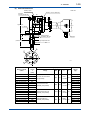
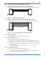
1-13
Flameproof High-temperature Detector (ZS8D-H-J-L-010-2--N-H)
— Model for Electric Heater Providing Heat Insulation—
Unit: mm
<3> Ejector
inlet
A
Approx. 280
Ejector
<1> Reference
gas outlet
<3> Ejector
outlet
ø155
ø130
Approx. 83
14
Approx.
100
Approx. 250
Approx. 93
A
Insertion
length l
(405)
(Approx. 150)
Section A-A
<1> Reference gas inlet
Approx. ø150
<2>Calibration
gas inlet
JIS 5K-65-FF flange
(or equivalent)
Check valve
Two G3/4
openings for wiring
<1>
Reference gas
inlet/outlet
<2>
Calibration
gas inlet
<3>
Ejector
inlet/outlet
ZS8D-H-J-L-010-2--N-HJ
Rc1/4
Rc1/4
Rc1/4
ZS8D-H-J-L-010-2--N-HA
1/4NPT
1/4NPT
1/4NPT
Model and Suffix Codes
F1.8E.ai
Weight (kg)
Approx. 11.8
IM 11M7A3-01E
1-14
<1. General>
1.2.4 High Temperature Probe Adaptor ZS8P-H
(1) Specifications
The ZS8P-H probe adaptor is required for the ZS8D-H high-temperature probe.
Sample Gas Temperature: 0 to 800°C (when SUS310S probe is used)
800 to 1400°C (when SiC probe is used)
Sample Gas Pressure: −1.5 to +5 kPa
Insertion Length: 0.5 m, 0.7 m, 1.0 m,1.5m
Material in Contact with Gas: SiC or SUS 310S, SUS304, flange (SUS304)
Installation: Flange mounting (FF or RF type)
Flange; JIS 10K-100-FF SUS304, JPI Class 150-4-RF SUS304, ANSI Class
150-4-RF(no serration) SUS304, and DIN PN10-DN100-A SUS304.
Probe mounting angle; Vertically down (within ± 5°)
SUS310S probe can be mounted horizontally.
Case Material:
SUS304, Aluminum alloy
Weight:With insertion length of 0.5 m, approx. 10 to 12 kg (JIS/JPI/ANSI/
DIN)
0.7 m, approx. 10.5 to 12.5 kg (JIS/JPI/ANSI/DIN)
1 m, approx. 11 to 13 kg (JIS/ANSI)
1.5 m, approx. 12 to 14 kg (JIS/ANSI)
(2) Model and Suffix Codes
[Style: S2]
Model
Suffix code
Option
code
Description
ZS8P
-H
········
High Temperature probe adaptor
Probe material
-A
········
SUS310S (0° to 800°C)
-B
········
SiC
-050
········
0.5m
-070
········
0.7m
-100
········
1.0m
-150
········
1.5m
-0
········
Discharge outside furnace (*2)
········
JIS 10K-100-FF SUS304
Insertion length
Sample gas
(exhaust method)
Flange joint connection
Ejector inlet joint
(*3)
-J
(800 to 1400°C) (*1)
-K
········
JPI Class 150-4-RF SUS304
-A
········
ANSI Class 150-4-RF SUS304
-E
········
DIN PN10-DN100-A SUS304
J
········
Rc1/4 (specified for JIS and JPI flanges)
A
········
1/4NPT (specified for ANSI and DIN flanges)
Heat insulation jacket
/JP
For probe adaptors
Tag plate
/SCT
Stainless steel tag plate
(*1)
(*2)
(*3)
IM 11M7A3-01E
If the temperature inside the furnace is 800°C or more, select -B.
Select whether to discharge mixed gases (the sample gas sucked in by the ejector plus the ejector air) outside the furnace or to
recirculate them in the furnace.
The probe adaptor is equipped with an auxiliary ejector assembly as standard.
1-15
<1. General>
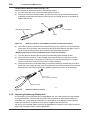
(3) External Dimensions
Unit: mm
Auxiliary ejector
Gasket (1.5 mm in thickness)
Air ejector
mounting port (Rc1/2)
180
Approx. 215
<1> Flange
Ø155
Ø60.5
80
Ø60.5
ØA
t
Approx. 48
100
(Insertion length L)
Mounting flange
provided by the user
Detector
Probe for high-temperature use
SiC
Ø52 or more
Ø30
C
ØA
F08.ai
ØB
Model and Suffix
Codes
Insertion
Length
l
(mm)
<1>Flange (mm)
Flange
ØA
ØB
C
t
Weight
(kg)
ZS8P-H--050-0-JJ
500
Approx. 10 kg
ZS8P-H--070-0-JJ
700
Approx. 10.5 kg
ZS8P-H--100-0-JJ
1000
ZS8P-H--150-0-JJ
1500
Approx. 12.0 kg
ZS8P-H--050-0-KJ
500
Approx. 12.0 kg
JIS 10K-100-FF SUS304
(or equivalent)
210
175
19 dia.
8 holes
18
Approx. 11.0 kg
ZS8P-H--070-0-KJ
700
ZS8P-H--100-0-KJ
1000
ZS8P-H--150-0-KJ
1500
Approx. 14.0 kg
ZS8P-H--050-0-AA
500
Approx. 12.0 kg
JPI CLASS 150-4-RF
SUS304 (or equivalent)
229 190.5
19 dia.
8 holes
24
Approx. 12.5 kg
Approx. 13.0 kg
ZS8P-H--070-0-AA
700
ZS8P-H--100-0-AA
1000
ZS8P-H--150-0-AA
1500
Approx. 14.0 kg
ZS8P-H--050-0-EA
500
Approx. 10.5 kg
ZS8P-H--070-0-EA
ZS8P-H--100-0-EA
ZS8P-H--150-0-EA
700
1000
1500
ANSI CLASS 150-4-RF
SUS304 (or equivalent)
DIN PN10-DN100-A
SUS304 (or equivalent)
228.6 190.5
220
180
19 dia.
8 holes
19 dia.
8 holes
24
20
Approx. 12.5 kg
Approx. 13.0 kg
Approx. 11.0 kg
Approx. 11.5 kg
Approx. 12.5 kg
IM 11M7A3-01E
1-16
<1. General>
1.2.5 Flameproof Converter ZS8C
(1) Specifications
Display Section:Measured value display section: 4-digit LED; Talk and response display: 40character dot matrix LCD with backlight
Display Content:
LED;
Oxygen concentration (vol%), error code display
LCD; Measured value group A (1st level)
Analog bar (output range, alarm setpoints, simultaneous display),
max./min. oxygen values, average value (period setting possible), cell emf
(mV), clock (year/month/day/hour/minute)
Measured value group B (2nd level)
Span correction rate/record, zero correction rate/record, cell response time
(sec.), cell resistance (Ω), cell condition, estimated cell life-span, heater ontime rate
Setpoint group C (calibration related)
Calibration gas concentration (%O2 ), calibration mode (one-touch, semiautomatic, automatic), stabilization time , calibration time, calibration cycle,
calibration start time
Setpoint group D (output related)
Output range 1,2 (%O2 ), presence or absence of output hold/ preset value,
analog output smoothing constant
Setpoint group E (alarm)
HH alarm, H alarm, LL alarm and L alarm setpoints, contact output delay
(sec.)/hysteresis (% span)
Status message group
Self-diagnosis, calibration, warm-up, stabilization, abnormal content
Talk and response message group
Calibration operation indicator, component check indicator, password entry
indicator
Help message:
Information supplementary to display content
Analog Output Signal:
4 to 20 mA DC (max. load resistance 550Ω), Input/output isolation
Range; any settings between 0 to 5 through 0 to 25 vol%O2; switching between 2
ranges by external contact input possible (optional); partial range possible
(span/zero rate ≥ 1.3)
Output dumping; 0 to 255 seconds
Dumping released during abrupt output change (releasing range: 0 to 3.0 vol%)
Hold/non-hold selection, preset value setting possible at hold
Contact output signal:
3 points, contact capacity 30 V DC 2A, 250 V AC 2A (resistive load)
Fail-safe condition (normally energized/normally de-energized) selectable, NO/NC selectable
using jumper pin
Delay function (0 to 255 sec.) and hysteresis function (0 to 25vol%O2) can be set for Hi/Lo
alarm.
IM 11M7A3-01E
1-17
<1. General>
The following functions are programmable for each
contact output; (1) Abnormal (self-diagnosis) (2) HiHi alarm (3) Hi alarm (4) LoLo alarm
(5) Lo alarm (6) Entry (7) Range switching answerback (8) Warm-up (9)
Reduction of calibration-gas pressure (repeat output of contact input) (10)
Calibration (11) Blow-back
If any combination is applicable during default, the contact points will operate.
Contact point 1; NC, normally energized (1) Abnormal
Contact point 2; NO, normally de-energized (6) Entry + (10) Calibration + (8) Warm-up
Contact point 3; NO, normally de-energized, (3) Hi alarm + (5) Lo alarm
Contact Output for Solenoid Valve:
Solid State Relay (Triac) output: 2 points
Contact capacity; 250 V AC, 1 A
Leakage current at SSR OFF; 3 mA or less
Contact output for ejector air stop solenoid valve:
Contact capacity; 250 V AC, 1 A (load resistance)
* In the case of a probe with electric heaters, if the heater temperature falls below ±10°C against setting temperature for
some reason (or if the power goes off), the ejector stops.
Serial communications: with an RS-422-A interface
Self-diagnosis:Abnormal cell, abnormal cell temperature (low)(high), abnormal analog circuit,
abnormal calibration, abnormal ROM/RAM, power failure
Contact Input (optional):
2 points, isolated
Contact input or voltage input
ON
OFF
Contact input
200 Ω or less
100 kΩ or more
Voltage input
−1 to +1 V DC
−4.5 to +2.5 V DC
or more
The following functions are programmable for each contact input:
(1) Reduction of calibration-gas pressure
(2) Range switching
(3) External calibration start
(4) Process abnormal alarm
(5) Blow-back start
Calibration:
Calibration method; One-touch, automatic/semi-automatic (optional)
All are operated by a talk-and-response procedure with the LCD panel. With
automatic/semi-automatic, either zero or span can be skipped.
Calibration-gas concentration setting range; 0.3 to 25 vol%O2
(minimum setting unit: 0.01 vol%O2 )
Use the standard zero and span gases which are gas mixtures of nitrogen and about
10% oxygen for an 80 to 100% scale.
IM 11M7A3-01E
1-18
<1. General>
Ambient Temperature: −20 to +55°C
Power Supply: 100, 115, 220, 240 V AC +10%, −15%, 50/60 Hz
Construction: JIS C0920 waterproof, NEMA3 or equivalent (when the openings for conduits are
completely sealed)
Power Connection Inlet: Seven G3/4 holes
Air-purge:
Rc1/4 or 1/4NPT(F) connection (optional)
Approx. 1 l/min. at 50 kPa
Note that the number of the power connection inlets becomes six when purging.
Installation:
Wall or pipe mounting
Case:
Aluminum alloy
Paint Colors:
0.6GY3.1/2.0 (for instrument front cover) and 2.5Y8.4/1.2 (instrument case)
Paint:
Baked epoxy resin
Weight:
Approx. 19 kg (100 to 115 V AC)
Approx. 20.5 kg (220 to 240 V AC)
(2) Model and Suffix Codes
Model
Option
code
Suffix code
Description
ZS8C
·· ·················
········
Converter
Flameproof
standard
-J
········
Exd II BT6 (Max. surface temperature 85°C)
-3
········
220V AC, 50/60Hz
-4
········
240V AC, 50/60Hz
-5
········
100V AC, 50/60Hz
-8
········
115V AC, 50/60Hz
-0
········
For detector heat insulation provided by steam heaters
-1
········
For detector heat insulation provided by electric heaters
Power supply
Auxiliary heater
thermostat for
probe (*1)
Panel
-E
········
English
-J
········
Japanese
/W
With wall mounting bracket
/P
With pipe mounting bracket
/AP2
1/4NPT(F)
/AP1
Rc1/4
Wall mounting
Air-purge connection
(*1)
A steam heater [-0] must be specified when heavy oil fuel, gas and heavy oil fuel mixture is used or clew point temperature of
exhaust gas is about 130°C.
(Notes)
(1)
(2)
(3)
(4)
Always use the specified external cable lead-in apparatuses given in the table below.
The number of mountable external cable lead-in apparatuses is as follows:
* Cable gland: up to 7
As standard, three cable glands (G9601AE) for the external cable lead-in apparatuses are mounted on the cable inlet ports for
the power supply and output signal. On the remaining four ports, blind plugs are mounted.
If any signal other than the power supply and output signal is required, additionally prepare the following parts as necessary
External Cable Lead-in Apparatus
Name
CABLE GLAND
IM 11M7A3-01E
Part No.
Description
G9601AE
Cable O.D. ø10 to ø13.5
Remarks
Cable gland
1-19
<1. General>
(3) External Dimensions
Unit: mm
MEAS
MAINT
ALM
FAIL
DATA
Four 10 mm dia.
openings
vol%O
401
112
79
303
Approx.54
2-inch (JIS 50 A) mounting
pipe (option code: /p)
28.5 28.5 28.5 28.5 28.5 28.5
186.5
103.5
Six G3/4 openings for wiring (with flame arrester)
Seven G3/4 openings for wiring (without flame arrester)
55.5
Purge air inlet (optional)
(with flame arrester)
34
Wall-mounting bracket
(code: /W)
Option code:
/AP1: Rc 1/4
/AP2: 1/4 NPT
Weight: Approx. 20 kg
Four 9 mm dia. openings
(use M8 screws for wall mounting)
Wall-mounting
dimensions
112
F1.10E
210
IM 11M7A3-01E
1-20
<1. General>
1.2.6 Options
(1) Check Valve K9292DN/K9292DS
This is used to prevent entry of the process gas into the calibration-gas line. It is incorporated in
the product as standard. If it is necessary to have one as a spare part, select it according to the
specifications.
Connection:
Rc1/4 or 1/4NPT (F)
(R1/4 or 1/4NPT (M) connectable)
Material:
SUS304
Supply Pressure:
Between 150 kPa to 350 kPa
Weight:
Approx. 40 g
Unit: mm
K9292DN : Rc1/4(A), R1/4(B)
K9292DS : 1/4NPT(A), 1/4NPT(B)
A
Approx. 19
B
Approx. 54
F11.1.EPS
(2) Auxiliary Ejector Assembly
K9292VA/K9292VB (for detector)
K9292WA/K9292WB (for probe adaptor)
Assemblies for both the detector and probe adaptor are available. If it is necessary to have one as a
spare part, select it according to the specifications.
Ejector Joint
K9292VE/K9292VF (for detector)
K9292WC/K9292WD (for probe adaptor)
Ejector Air Pressure: 20 kPa for detector
98 kPa for probe adaptor
Air Consumption:
4 l/min. for detector
40 l/min. for probe adaptor
Connection:
Rc1/4 or 1/4NPT(F)
Material:
SUS304
Tube Connection:
(ø6/ø4 or 1/4-inch copper or stainless-steel tubing)
Pressure Gauge Assembly
Pressure Gauge Type: JIS B7505, A1.5U3/8X75
Material in Contact with Gas: SUS316
IM 11M7A3-01E
Case Material:
Aluminum alloy (painted in black)
Scale:
0 to 50 kPa (K9292VA/VB for detector)
0 to 200 kPa (K9292WA/WB for probe adaptors)
Tube Connections:
Rc1/4 or 1/4NPT, SUS304
1-21
<1. General>
Needle Valve
Connection: Rc1/4 or 1/4NPT(F)
Material: SUS316
(Note)Pipes and connectors other than the above are not supplied.
Part No.
Part No.
Part No.
K9292VB
Auxiliary ejector assembly for detector, 1/4NPT with a pressure gauge and needle valve
K9292VA
Auxiliary ejector assembly for detector, Rc1/4 with a pressure gauge and needle valve
K9292VF
Ejector joint (for auxiliary ejectors), 1/4 NPT
K9292VE
Ejector joint (for main ejectors), Rc1/4
K9292WB
Auxiliary ejector assembly for probe adaptors, 1/4 NPT, with a pressure gauge and needle
valve
K9292WA
Auxiliary ejector assembly for probe adaptors, Rc1/4, with a pressure gauge and needle valve
K9292WD
Ejector joint (for probe adaptor), 1/4NPT
K9292WC
Ejector joint (for probe adaptor), Rc1/4
External Dimensions
Pressure Gauge Assembly
Ejector Joint
Unit: mm
<3>
Nozzle
Pressure Meter
(Note 1)
Approx.
70
39
<2>
38
Ejector joint
K9292WC/
K9292WD
(for probe
adaptor)
Needle valve
ø43
Approx. 67
(Height when
fully opened)
<1>
<1>
<1>
Approx.
88
<1>
<1>
To be constructed
by the customer
Instrument
air inlet
<2>
40
Approx. 65
Tee
24
<1>
Ejector joint
K9292VE/
K9292VF
(for detector)
Auxiliary Ejector Assembly K9292VA/K9292VB/K9292WA/K9292WB
Parts number
Specification
<1>
<2>
F1.12E.ai
<3>
K9292VA
For Detector use
Rc1/4
R1/8
—
K9292VB
For Detector use
1/4NPT
R1/8
—
K9292WA
For Probe adaptor use
Rc1/4
R1/2
Pipe O.D. ø6
K9292WB
For Probe adaptor use
1/4NPT
R1/2
Pipe O.D. ø1/4
(Note 1) The connector of auxiliary ejector assembly is a dedicated connecter with nozzle function.
IM 11M7A3-01E
1-22
<1. General>
(3) Flow Setting Unit ZA8F
Specifications
Used when instrument air is provided. This unit controls flow rates of calibration gas and reference
gas and consists of flowmeter and flow rate control valve.
FIowmeter:
Calibration gas; 0.1 to 1.0 l/min. Reference air; 0.1 to 1.0 l/min.
Construction:
Dust-proof and rainproof construction
Case Material:
SPCC (Cold rolled steel sheet)
Painting: Baked epoxy resin, Dark-green (Munsell 2.0 GY 3.1/0.5 or equivalent)
Tube Connections:
Rc1/4 or 1/4NPT (F)
Reference Air pressure:Clean air supply of measured gas pressure plus approx. 50 kPa G
measured gas pressure plus approx.150 kPa (maximum pressure rating
is 300 kPa) when a check valve is used (pressure at inlet of the autocalibration unit)
Air Consumption:
Approx. 1.5 l/min
Weight:
Approx. 2.3 kg
Model and Suffix Codes
Suffix code
Option
code
···························
········
Model
ZA8F
Joint
Style code
IM 11M7A3-01E
Description
Flow setting unit
-J
········
Rc1/4
-A
········
1/4NPT (F) with adaptor
········
Style C
*C
1-23
<1. General>
External Dimensions
180
Ø6 holes
Unit: mm
140
7
REFERENCE CHECK
REFERENCE SPAN
ZERO
2-inch mounting pipe
235.8
222.8
Calibration gas outlet
Span gas inlet
Reference gas outlet
Zero gas inlet
Piping connection port A
32
ZERO
IN
SPAN
IN
CHECK
OUT
AIR
IN
REF
OUT
70
35
20
35
35
35
35
Model
Piping connection port A
ZA8F-J*C
5-Rc1/4
ZA8F-A*C
5-1/4NPT
20
Weight: Approx. 2.3kg
7
Instrument air inlet
CHECK
OUT
Flow
meter
ZERO
GAS IN
SPAN
GAS IN
REF
OUT
Flow
meter
AIR IN
Instrument air
Approx 1.5 l/min.
Air set
Air pressure :
without check valve ; measured gas pressure + approx.50 kPaG
with check valve ; measured gas pressure + approx.150 kPaG
F13.14.EPS
(4) Air Set G7003XF/K9473XK
Specifications
Primary Pressure: Max. 1 MPa G
Secondary Pressure: 0 to 200 kPa G
Connection: Rc1/4 or 1/4NPT (F)
Material: Zn alloy
IM 11M7A3-01E
1-24
<1. General>
Part No.
Part No.
Description
G7003XF
K9473XK
Primary Pressure
Max. 1 MPa G
Max. 1 MPa G
Secondary Pressure
0 to 200 kPa G
0 to 200 kPa G
Rc1/4
1/4NPT with adaptor
Zn alloy
Zn alloy
Connection
Material
External dimensions
max. 55
Unit: mm
Max. 210
Ø74
Panel (Horizontal
mounting)
Secondary
pressure
gauge
Panel (Vertical
mounting)
Secondary
88
Primary
G7003XF: Rc1/4
K9473XK: 1/4NPT connector
Approx. 122
weight: 1.0 kg
Air Set (G7003XF/K9473XK)
(5) Calibration Gas Unit
This unit consists of a zero-gas cylinder, pressure regulator, and case assembly.
Zero Gas Cylinder G7001ZC
Capacity: 3.4 l
Filled Pressure: 9.8 to 12 MPa G
Gas Composition: 0.95 to 1.0 vol%O2 + N2 balance
Cylinder Pressure Regulator G7013XF/G7014XF
Pressure Gauge:
Primary;
0 to 14.8 MPa G
Secondary;
0 to 0.4 MPa G
Connection:
Inlet;
W22 14 threads, right-hand screw
Outlet;
Rc1/4 or 1/4NPT (F)
Body Material: IM 11M7A3-01E
Brass
F1.14E.ai
<1. General>
1-25
Case Assembly E7044KF
Case Material:
SPCC
Case Paint:
Baked epoxy resin
Paint Color:
Jade green (Munsell 7.5BG 4/1.5)
Mounting:
Two-inch pipe mounting
Weight:
Approx. 3.6 kg
External dimensions
Calibration Gas Unit
Unit: mm
324
225
180
496
Regulator
G7013XF/
G7014XF
Zero gas cylinder
(G7001ZC)
(158.3)
(160)
2-inch pipe
(O.D.:60.5)
The oblique line is an opening portion.
F1.15E.ai
Note: The zero gas cylinder and the regulator valve are not included in the E7044KF (case assembly)
485
325
G7001ZC Zero-gas Cylinder
140
(Note) Export of such high pressure filled gas cylinders to
most countries is prohibited or restricted.
IM 11M7A3-01E
1-26
<1. General>
Cylinder Pressure Regulator
Approx. 112
Secondary Primary
pressure
pressure
gauge
gauge
W22 (Righthanded screw)
Stop valve
ACH
IN
* Outlet
Primary
safety valve
HO
TA K
I
ACH
O
IH
TAK
Regulator handle
Unit : mm
Secondary
safety valve
Approx. 59
Approx. 82
Approx. 163
Approx. 174
F1.16E.ai
Part No.
IM 11M7A3-01E
* Inlet/Outlet
G7013XF
W22 14 threads/ Rc1/4
G7014XF
W22 14 threads/ 1/4 NPT (F)
Weight: Approx. 1kg
2.
<2. Installation>
2-1
Installation
This analyzer is an instrument of flameproof construction and has been certified by a public agency
based on the Industrial Safety and Health Law (of Japan). For the wiring and piping work in the
case of installing this analyzer in a hazardous area, do the work in accordance with the see USER’S
GUIDELINES for Electrical Installation for Explosive Gas Atmospheres in General Industry, issued by
the Research Institute of Industrial Safety of the Ministry of Labor in Japan, 1994.
This chapter describes procedures for installation of the major units composing the ZS8 flameproof
zirconia oxygen analyzer (including those in optional use) as shown below.
2.1
Section 2.1
Flameproof general-purpose detector
Section 2.2
Flameproof high-temperature detector (including high-temperature probe adaptor)
Section 2.3
Flameproof converter
Section 2.4
Flow setting unit
Section 2.5
Calibration gas unit case
Installation of Flameproof General-purpose
Detector
2.1.1 Installation Site
The following criteria should be taken into consideration when selecting the location for installing the
detector.
(1) The explosion protection standards are satisfied.
(2) There should be easy access to the detector to ensure safe work in checking and maintenance.
(3) The ambient temperature should not be too high (below 60°C) and the terminal box should not
be subject to strong radiant heat.
(4) There should be no vibration.
2.1.2 Probe Insertion Hole
When constructing the probe insertion hole, take the following into consideration:
(1) Do not point the detector probe tip upward.
(Note)This should be observed so that the sensor (cell) in the probe tip is not affected by droplets which may cause problems
such as condensation.
(2) Mount the detector probe at a right angle to the measuring gas flow or with the probe tip located
on the downstream side.
(3) If the vent gas is to be returned to the inside of the furnace using a general-purpose detector,
devise the mounting flange pipe so that its inner surface is placed outer than the ejector air return
port position because the return port radius is 41 mm.
Also, place the filter root position 30 mm or more away from the inner surface of the furnace wall.
If it is less than this distance, if may be affected with the ejector’s return air.
(4) Adjustment of deflector mounting direction
Adjust the position of the filter protector (deflector) of the probe tip so that it is a right angle to the
gas flow as shown in Figure 2.1 for both general-purpose and high-temperature detectors. The
deflector direction can be readily changed by loosening the lock nut on the probe tip. Figure 2.1
shows an example of probe insertion hole construction work.
IM 11M7A3-01E
2-2
<2. Installation>
Locknut
(Vertical)
Range of possible insertion
hole construction
100mm
Flange :
Install the rating
flange the same as
that for the detector.
Gas flow
Deflector
Deflector adjustment
(Horizontal)
(Note)
Diameter of
60mm or more
100mm
(Note) : 95mm dia. or more for return to inside of furnace
JIS flange
ANSI flange
F2.1E.ai
Figure 2.1
Example of Probe Insertion Hole Construction Work
2.1.3 Detector Installation
In the detector, zirconia (ceramic) is used as a sensor. Be careful not to subject the sensor to strong
shock such as from being dropped, when the detector is installed.
Prepare and use a gasket on the tie-in flange surface to prevent gas leakage. It is required that
the gasket material be heat-resistant and corrosion-resistant conforming to the properties of the
measuring gas. Table 2.1 shows the parts which are necessary for installing the detector.
Table 2.1
Parts Necessary for Installing the Detector
Mounting flange
rating
JIS 10K-100-FF
JPI CLASS150-4-RF
DIN PN10-DN100-A
Part
Quantity
Gasket
1
Bolts (M16 x 80)
8
Nuts (M16)
8
Washer (for M16)
16
Gasket
1
Bolts (5/8-11UNC x 80)
8
Nuts (5/8-11UNC)
8
Washer (for 5/8-11UNC)
16
Gasket
1
Bolts (M16 x 80)
8
Nuts (M16)
8
Washer (for M16)
16
Remarks
The gasket should be heat-resistant and
corrosion-resistant.
The gasket should be heat-resistant and
corrosion-resistant.
The gasket should be heat-resistant and
corrosion-resistant.
The following is a point to be taken into consideration in installation work:
(Flameproof Detector)
If the detector is to be mounted horizontally, point the cable inlet port downward.
2.1.4 Reference Air Outlet
Do not block the reference air outlet. Otherwise, the terminal box inner pressure increases and an
indication error may occur. To prevent rain water from entering through the reference air outlet, you
can connect a short pipe (100 mm maximum) with a minimum of 6-mm ID to the outlet.
IM 11M7A3-01E
2-3
<2. Installation>
2.1.5 Heat Insulation
CAUTION
For explosion protection standards, the lagging surface temperature must be 200°C or less.
The path of the gas flow in the probe must be heat-insulated above the dew point to prevent clogging
due to condensation.
a. Heat-insulate the flame arresters at both the measuring gas inlet and outlet using an electric
heater. Make the heat insulation temperature above the dew point and at 195°C or less. The
electric heater or steam trace copper tubing can be supplied optionally.
b. Heat-insulate the mating flange section so that the inside of the measuring gas suction pipe does
not drop below the dew point using steam tracing.
c. Also heat-insulate the air ejector so that it is above the dew point. As the strength of the
measuring gas suction is weak (about 300 ml/min, supply an air flowrate of about 3 l/min), there
will be no problem in heat insulation by using lagging only, except when the ambient temperature
is extremely low. Prevent rain water from entering the air ejector.
In addition, the problem of supply air piping clogging is better solved by heating the piping by
winding it around the detector heater section before connecting it to the ejector.
d. Cover the heat-insulating section by steam trace or the electric heater with ceramic wool or the
like to enhance the heat insulation effect.
2.2
Installation of Flameproof High-temperature
Detector
2.2.1 Installation Site
Install the flameproof high-temperature detector in a location where:
(1) the explosion protection standards are satisfied.
(2) there is easy access to the detector and safe work is ensured in checking and maintenance,
(3) the ambient temperature is below 60°C and the terminal box is not subject to radiant heat.
(4) there is no vibration.
2.2.2 Probe Insertion Hole
The ZS8D-H flameproof high-temperature detector is used in combination with the ZS8P-H hightemperature probe adaptor. If this high temperature detector is to be used, provide the probe insertion
hole for the high temperature probe adaptor.
When constructing the probe insertion hole, take the following into consideration:
(1) If the high-temperature probe adaptor is made of silicon carbide (SiC), construct the hole so that
the probe is placed vertically (tilting: within 5 degrees).
(2) If the high-temperature stainless steel probe adaptor is to be installed horizontally, the probe tip
should not be higher than the flange center.
Figure 2.2 shows examples of constructing the probe insertion hole.
IM 11M7A3-01E
2-4
<2. Installation>
Flange: Install the rating flange
the same as that for
the probe adaptor
100mm
A space of 52 mm or more
in diameter, and long enough
for the length of the probe
100mm
A space of 52 mm or
more in diameter, and
long enough for the length
of the probe
Never mount the probe
with its tip higher than
the base
The allowable margin for probe
tilt is within ± 5°.
An SiC probe shall be mounted vertically.
Flange: Install the rating
flange the same as
that for the probe
adaptor
Horizontal mounting is used with a SUS probe.
F2.2E.ai
Figure 2.2
Examples of Probe Insertion Hole Construction
2.2.3 Detector Installation
In the detector, zirconia (ceramic) is used as the sensor. Be careful not to subject it to strong shock
such as from being dropped, when the detector is installed. The same caution applies to a hightemperature SiC probe adaptor.
Provide a gasket on the tie-in flange surface to prevent gas leakage. It is required that the gasket
material be heat-resistant and corrosion-resistant conforming to the properties of the measuring gas.
Table 2.2 shows the parts which are necessary for installing a high-temperature probe adaptor.
Table 2.2
Parts Necessary for Installing High Temperature Probe Adaptor
Mounting flange
rating
JIS 10K-100-FF
JPI CLASS150-4-RF
DIN PN10-DN100-A
Part
Quantity
Gasket
1
Bolts (M16 x 80)
8
Nuts (M16)
8
Washer (for M16)
16
Gasket
1
Bolts (5/8-11UNC x 80)
8
Nuts (5/8-11UNC)
8
Washer (for 5/8-11UNC)
16
Gasket
1
Bolts (M16 x 80)
8
Nuts (M16)
8
Washer (for M16)
16
Remarks
The gasket should be heat-resistant and
corrosion-resistant.
The gasket should be heat-resistant and
corrosion-resistant.
The gasket should be heat-resistant and
corrosion-resistant.
The following is a point to be taken into consideration in installation work:
(1) Install the high-temperature detector considering the attitude of the detector. In particular, if it
is to be installed horizontally, be careful that the detector probe tip is not pointed upward (it is
recommended that detector be installed vertically unless otherwise restricted by the location).
(2) When mounting the high-temperature probe adaptor, be sure to insert a gasket between the
flange surfaces to prevent gas leakage. Special care should be taken for air-tightness, if there is
negative pressure in the furnace, to prevent air leakage into the furnace.
(3) When installing the detector with an attitude other than vertical, do it so that the cable inlet port is
pointed downward.
IM 11M7A3-01E
2-5
<2. Installation>
Install the detector so
that the probe tip is
pointed downward.
For SiC probes,
mount it within
5 degrees of the vertical.
F2.3E.ai
Figure 2.3
Installing the High-temperature Detector
2.2.4 Ejector Installation
For a high-temperature detector, two ejectors (main ejector: attached as standard; auxiliary ejector:
optional) are required.
Only venting out of the furnace is applied for the measuring gas suctioned by the ejector in the case of
a high-temperature probe adaptor.
(1) Ejector Installation
Install the main ejector for the detector and the high-temperature auxiliary ejector in the position
shown in Figure 3.3. Both main and auxiliary ejectors can be installed in any direction at 90° angles.
If soot accumulates on the bottom of the probe and corrodes it, it is recommended that the ejector be
installed pointing downward for purging.
(2) Piping
CAUTION
The temperature of gas from outlet of ejector is high temperature (about 200°C).
Release it to safe place please.
It would arouse furns and furmiry accident.
a. Install the pressure gauges and supply the air adjusting the needle valves as near the ejector as
possible. However, if the temperature of the pressure gauge mounting location exceeds 40°C,
install them in a location at 40°C or less away from the ejector.
b. Use copper tubes or stainless steel tubes of OD 6 mm / ID 4 mm for piping. Take some
measures such as winding the ejector's air supply tube around the detector itself (near the
sensor) if the ambient temperature is low, so that the tube does not become clogged due to
condensation by the cooled ejector (see Figure 2.5).
IM 11M7A3-01E
2-6
<2. Installation>
c. Ejector outlet piping:
For the detector with a high-temperature probe adaptor, the measuring gas cannot be returned
to the furnace. Both the main ejector for the detector and the auxiliary ejector for the probe
adaptor are influenced by back pressure, so do not connect any piping through the ejector outlet.
However, to prevent rain water from entering the ejector, you can connect a 1/4-inch (10.5mm
O.D.) pipe with a maximum length of 300 mm, bent slightly.
d. If there is positive pressure at the sampling point above 500 Pa and also release to the
atmosphere is possible, main and auxiliary ejectors are not necessary. In this case, In this
case, mount the needle valve on the auxiliary ejector mounting port and adjust it so that the
temperature near the probe adaptor is 200°C. Also, directly connect a suitable needle valve
which can adjust the vent gas quantity to the main ejector mounting port. Adjust the needle valve
so that it will vent a gas quantity of 300 to 500 ml/min. This is because abnormal overheating of
the detector cell section due to much sample gas exhaust should be prevented.
2.2.5 Heat Insulation
See section 2.3 “Heat Insulation.”
2.2.6 Blocking Radiant Heat
If the surface temperature of the flame arrester portion of the detector is likely to exceed 200°C due to
heat radiating from the furnace wall or other heat sources, block the radiant heat with a blocking plate
or take other measures.
2.3
Heat Insulation
CAUTION
For explosion protection standards, the lagging surface temperature must be kept to 200°C or less
strictly.
To prevent the block by dew in the gas flowing pipe on probe, keep the temperature higher than
dew-point.
2.3.1 Surface Temperature of Detector
The surface temperature of the detector must be kept below 200°C in accordance with the explosion
protection standards. The ambient temperature significantly changes over the course of the year, and
the operating condition changes as the load changes. Therefore, if factors that change the surface
temperature change, be sure to check that the surface temperature is not above 200°C. If the surface
temperature is above 200°C, reduce it to below 200°C by the methods described later (see section
2.3.3).
2.3.2 Portions Requiring Heat Insulation and Temperature to be Maintained
(1) Detector Sensor Portion’s Flame Arrestor
With regards to the heater for the frame arrestor, you can select either en electric heater or
steam heater by specifying the model code.
The maximum controllable temperature of the electric heater is about 130°C. Accordingly, the
electric heater can be used for gas burning or other applications for which the oxygen dew point
is 130°C or less.
IM 11M7A3-01E
2-7
<2. Installation>
a. Heat Insulation by Electric Heater
Use heat insulating material to maintain the temperature of the frame arrestor portion above the
dew point of the measuring gas.
Set the surface temperature of the electric heater to 160°C or less in order to prevent the thermal
fuse built in the electric heater from meting down.
b. Heat Insulation by Steam Heater
Use a steam heater to heat the frame arrestor portion to maintain its temperature above the dew
point of the measuring gas. Be sure to maintain the surface temperature of the steam heater
below 200°C in accordance with the explosion protection standards.
(2) Detector’s Main Ejector
Use a heater (electric or steam) to heat the main ejector to maintain its temperature above the
dew point of the measuring gas. Be sure to maintain the surface temperature of the heater below
200°C in accordance with the explosion protection standards.
Wrap an ejector air pipe around the heater portion of the detector in order to prevent clogging in
the ejector. (See Figure 2.5)
(3) Gas Suction Pipe of Detector Probe
As for general purpose detectors, use heat insulating material for the mating flange portion to
maintain the temperature of the gas suction pipe of the detector probe above the dew point of
the measuring gas. If necessary, use a steam heater, for example, to heat the gas suction pipe to
maintain its temperature as specified.
(4) Probe Adapter
Maintain the heat of the probe adapter to keep its temperature above the dew point of the
measuring gas. Although the probe adapter is not a flameproof instrument, be sure to maintain
its surface temperature below 200°C when using it in combination with the flameproof detector.
The surface temperature of the probe adapter should be measured on the surface of blind flange
on the opposite side of the probe.
2.3.3 Methods to Change the Surface Temperature
If the surface temperature does not fall within the specified range, use the following methods to
change the surface temperature so that it falls within the specified range.
<When the surface temperature exceeds 200°C>
(1)
If insulating material is used, reduce the thickness of the insulating material, or remove it
altogether. However, the surface temperature may fall below the dew point of the measuring gas
in locations where raindrops fall on the surface or the surface is subjected to a strong wind. In
such a case, provide a rain protection cover.
(2) Reduce the suction flowrate of the measuring gas of the probe adapter.
a. If the pressure in the furnace is negative, reduce the supply pressure to the ejector to reduce the
suction flowrate of the measuring gas. For the setting of the suction flowrate, see section 6.1.8
“Supplying Pressure to Ejector.”
If the suction flowrate is reduced, air is sucked from the ejector as a result of changes in the
pressure in the furnace, resulting in an indication error. Be sure to check to make sure air is not
sucked in.
b. If the pressure in the furnace is positive, reduce the aperture of the needle valve for the
discharge outlet of measuring gas to reduce the suction amount of measuring gas. For the
position of the needle valve, see section 5.1.2.
(3) If the surface temperature exceeds 200°C due to heat radiating from the furnace wall or other
heat sources, provide a blocking plate or heat insulating material between the furnace wall and
probe adapter and detector to block the radiant heat.
IM 11M7A3-01E
2-8
<2. Installation>
(4) If temperature rises significantly due to heat transfer, keep the mounting flange of the probe
adapter and detector as far away as possible from the furnace wall.
<When the surface temperature falls below the dew point of measuring gas>
(1) If the probe adapter and detector are not thermally insulated, insulate them. (See section 2.3) If
they are thermally insulated, enhance the thermal insulation effect by, for example, increasing
the thickness of the heat insulating material. A thermal insulating jacket is available as an option
to thermally insulate the detector and probe adapter. When installing the detector and probe
adapter in locations where raindrops fall on their surface or their surface is subjected to a strong
wind, the surface temperature is likely to fall below the dew point of the measuring gas, so be
sure to provide a rain protection cover.
Keep the surface temperature of the electric heater below 160°C and that of the probe adapter
below 200°C to prevent the thermal fuse built in the electric heater from melting down.
(2) Increase the suction amount of the probe adapter.
a. If the pressure in the furnace is negative, an increase in the supply pressure to the ejector
increases the suction flowrate of measuring gas. For the setting of the suction flowrate, see
section 6.1.8 “Supplying Pressure to Ejector.”
If there is a lot of dust, be careful, because an increase in the suction flowrate is likely to cause
clogging in the ejector.
b. If the pressure in the furnace is positive, increasing the aperture of the needle valve for the
discharge outlet of the measuring gas increases the suction amount of measuring gas. For the
position of the needle valve, see section 5.1.2.
(3) If the above measures do not raise the surface temperature of the probe adapter, ejector, or
mating flange above the dew point of measuring gas, heat them with heat sources such as a
steam heater.
2.3.4 Fitting a Thermal Insulating Jacket (Option)
Note: Wrap the ejector air pipe around the heater portion of the detector. Be sure to insulate the
exposed pipe and ejector air pipe that are not insulated by the thermal insulating jacket (option). Be
sure to insulate the ejector outlet pipe, too.
IM 11M7A3-01E
<2. Installation>
2-9
A. Heat insulation of detector
Please install the jacket as below:
In the case of electric heater
Procedure 1: Before install the jacket (Appearance)
Procedure 2:Fit the heat - insulate material (Plate)
Make the flange side of detector probe on top (The side of electric heater for
heat-insulation), undo the magic tape on plate heat-insulate material and let the
magic tape on side face to the terminal box of detector, than insert it to the plate
heat-insulate material.
Next. As photo above, stick the magic tape tightly.
IM 11M7A3-01E
2-10
<2. Installation>
Procedure 3:Fit the heat insulating material (Body)
Undo the magic tape on body heat insulate material, cover the heat-insulate
electric heater from side of detector terminal box, and take care of : make flexible
pipe from electronic hearter go through the surface of heat-insulate material ;
make the pipe from ejector go out from the hole in two side of heat-insulate
material.
Procedure 4:Fit the heat insulating material on the detector
Stick the magic tape of plate heat insulate material on the side of heat insulate
material (Body). And then stick the magic tape on the side of terminal box of
heat-insulate material (Body) to the detector, wrap the flexible pipe up with magic
tape on the side of plate heat insulate, stick it tightly and fix it by rope at last.
These are all procedures. Please confirm your fitting by the photo above.
IM 11M7A3-01E
<2. Installation>
2-11
In the case of steam hearter
Procedure 1:Wrap and fix the heat-insulate material
Wrap the copper pipe on the flame arrester of detector with ring-like heatinsulate material. Fix the ring-like heat-insulate on the copper pipe tightly by
magic tape.
Please refer to photo by procedure 5 that the installation of jacket is finished.
Procedure 2:Fit the heat insulating material (Plate)
Undo the magic tape on plate heat-insulate material, then insert it between the
upside of flange of detector probe and pipe of outlet of steam pipe. At last close
the inserting section tightly by magic tape.
IM 11M7A3-01E
2-12
<2. Installation>
Procedure 3:Fit the heat insulating material (Body)
Undo the magic tape on body heat insulate material, cover the copper pipe
of steam by heat-insulate electric material from side of detector terminal box.
Please take care of:
Make the pipe from ejector go out from the hole in two side of heat-insulate
material.
Procedure 4:Fix the heat insulating material (Body)
Confirm that the pipe of ejector and pipe for heat-insulate steam go out from the
heat-insulate material, stick the all magic tape of body.
IM 11M7A3-01E
<2. Installation>
2-13
Procedure 5:Fix the heat insulating material on the detector
Stick the magic tape of plate heat insulate material on the side of heat insulate
material (Body). And then wrap the detector up with magic tape of the side of
terminal box, stick it tightly and fix it by rope at last.
These are all procedure.
Please confirm your fitting by the photo above.
The heat-insulate effect would be weakened if heat-insulate section is got wet. Please set the
waterproof on the heat-insulate section.
If the heat-insulate material (Ceramic wool etc.) is not used by jacket, please ensure fully in heatinsulate section (Flame arrester section and ejector section).
Please set the waterproof on the heat-insulate section also.
B.
The heat-insulate in probe adapter
The heat-insulate in probe adapter is used by jacket as bellow:
Procedure 1:Wrap the heat-insulate jacket (For inside).
Warp the frame adapter with inside heat-insulate jacket.
IM 11M7A3-01E
2-14
<2. Installation>
Procedure 2:Fix the heat-insulate jacket (For inside).
Wrap the Frame adapter tightly with wrapped jacket, and fix it by magic tape.
Please make the ejector out from the heat-insulate jacket.
Procedure 3:Fit the heat-insulate jacket (For outside)
Please undo the magic tape of outside heat-insulate jacket, make the mounting
flange out from the jacket as photo above, then put the probe adapter (With
inside heat-insulate jacket) in it. Make the pipe from ejector go out from the hole
in two side of heat-insulate jacket.
IM 11M7A3-01E
2-15
<2. Installation>
Procedure 4:Fix the outside heat-insulate jacket
Finish the fitting of heat-insulate jacket by locking all the side magic tape.
Please confirm your fitting by the photo above.
If the condition temperature is below the dew point, please keep heat-insulate by steam or
electric heater.
If the heat-insulate material (Ceramic wool etc.) is not used by jacket, please ensure fully in heatinsulate section (Flame arrester section and ejector section). Please set the waterproof on the
heat-insulate section also.
2.3.5 Heating and Insulation Range when Not Using a Heat-Insulating Jacket
Heating and insulation work for the
flange and installation of heat
insulating material are carried out
by customer
◄▬
Ejector air outlet
Ejector
◄▬
air inlet
Inside the furnace
Outside the furnace
Select an electric heater or steam heater to heat and insulate the frame arrestor section.
(Steam inlet/outlet Rc 1/4)
When using an electric heater
When using a steam heater
Figure 2.4
Heating and Insulating Gas Flow Path Section
IM 11M7A3-01E
2-16
<2. Installation>
Be sure to heat and
insulate the steam pipe.
Heat and insulate the ejector to maintain its
temperature above the oxygen dew point (Note 1).
The pipe (for ejector air) needs to be heated and
insulated after it has been pre-heated.
Steam
(Detector’s ejector air pre-heating section)
Wrap the detector’s ejector air pipe firmly
around the steam pipe.
The ejector’s outlet pipe needs to
be heated and insulated.
Ejector air
outlet
E
D
F
C
B
B
B
B
C
F
E
A
A
Instrument air
Outside the furnace
Inside the furnace
Measuring gas
Figure 2.5
IM 11M7A3-01E
(Auxiliary ejector’s air
pre-heating section)
Wrap a steam pipe
around the probe
adapter, and then
closely wrap the
auxiliary ejector’s air
pipe around them.
This flange may be removed for maintenance.
When carrying out heating and insulation work,
separate the heating and insulation section on the
side of the flange into sections (A) to (F) to enable
the flange to be removed for maintenance (Note 2).
Note 1: For the sulfuric acid dew point, see the
separate table.
Note 2: One example of heating and insulating
sections (A) to (F) is to wrap glass wool
around the heating and insulation
section and then apply a waterproof
aluminum tape to secure it.
Work Example of Heating and Insulating Flameproof High-Temperature
Detector (Example of Heating and Insulation by Steam Heater)
<2. Installation>
2-17
Carry out heating and
insulation work to maintain
the temperature of the
ejector above the oxygen
dew point (Note 1).
Pre-heating section’s pipe (for ejector
air) needs to be heated and insulated.
The ejector’s outlet pipe needs to
be heated and insulated.
D
B
A
Measuring gas
C
C
A
D
B
Inside the furnace
Outside the furnace
Ejector air pre-heating section
(Wrap a pre-heating pipe firmly
around the wall surface of the
mating flange.)
↑
This flange may be
removed for maintenance.
When carrying out heating
and insulation work, separate
the heating and insulation
section on the side of the
flange into sections (A) to (D)
to enable the flange to be
removed for maintenance
(Note 2).
Instrument air
Sulfuric acid dew point (°C)
Figure 2.6
Note 1: For the sulfuric acid dew point,
see the separate table.
Note 2: One example of heating and
insulating sections (A) to (D) is to
wrap glass wool around the
heating and insulation section
and then apply a waterproof
aluminum tape to secure it.
Work Example of Heating and Insulating General-Purpose Flameproof Detector
(Example of Heating and Insulation by Electric Heater)
200
150
100
50
0
0
1
2
3
4
5
6
Sulfur content in fuel (%)
Cited reference: L.K. Rendle and R.D.
Figure 2.7
Sulfur Content in Fuel and Sulfuric Acid Dew Point (for reference)
IM 11M7A3-01E
2-18
<2. Installation>
2.4
Installation of Converter
2.4.1 Installation Site
Install the converter by selecting a location where:
(1) the explosion protection standards are satisfied.
(2) the indicated oxygen concentrations and messages are legible and key operation is easy
(avoiding exposure to direct sunlight),
(3) inspection and maintenance are easy,
(4) the ambient temperature is not too high (max. 55°C) and the temperature varies little
(recommended to vary no more than 15°C a day),
(5) the humidity is moderate (40 to 75% RH is recommended) and no corrosive gases are present,
(Note)If there is a corrosive gas, carry out air purging. The air-purge tube joints are optionally attached only when required.
(6) there is little vibration,
(7) the detector is installed relatively nearby.
2.4.2 Converter Mounting
The converter can be mounted either to a pipe (nominal 50A) or on a wall. The converter can also be
mounted at an angle, but as a rule, vertical mounting is recommended.
Carry out converter mounting in the following procedure:
Pipe Mounting
(1) Provide a pipe (nominal 50A, OD of 60.5 mm) for mounting the converter vertically with sufficient
strength.
(2) Mount the converter to a pipe. Fix the converter rigidly in the procedure shown in Figure 2.9.
Converter*
Threads*
Mounting pipe
(nominal 50A)
Nuts
Bracket
Washers*
Bolts
● Mounting Procedure
1. Screw four bolts into the bracket.
2. Sandwich the mounting pipe by screwing four bolts
into the threads through the bracket.
3. Fully tighten the bolts.
Bolts
F2.4E.ai
Figure 2.9
IM 11M7A3-01E
Pipe Mounting
<2. Installation>
2-19
Wall Mounting
(1) Drill four mounting holes on the wall as shown in Figure 2.10.
Unit: mm
4-ø9 holes or 4-M8 screws
112
210
Figure 2.10
F2.5E.ai
Machining of Mounting Holes
(2) Mount the converter. Securely fix the converter with four screws.
(Note)For wall mounting, install the wall mounting bracket on the back of the converter.
F2.6E.ai
Figure 2.11
2.5
Wall Mounting
Installation of Flow Setting Unit
This is necessary when the ZA8F flow setting unit is to be used.
2.5.1 Installation Site
Install the flow setting unit by selecting a location where:
(1) there is access for inspection and maintenance,
(2) the locations of the detector and converter mounting are nearby,
(3) there are no corrosive gases,
(4) the ambient temperature is not too high (up to 55°C) and temperature fluctuations are small, and
(5) there is little vibration.
IM 11M7A3-01E
2-20
<2. Installation>
2.5.2 Flow Setting Unit Mounting
The flow setting unit can be mounted on a pipe (nominal 50A) or on the wall. As the flow setting unit
incorporates a flowmeter, be sure to mount the unit vertically so that no error occurs. Mount the unit in
the following procedure:
Pipe Mounting
(1) Provide a vertical mounting pipe (nominal 50A, OD of 60.5 mm) with sufficient strength.
(2) Mount the flow setting unit to the pipe. Securely fix the mounting bracket to the pipe by fully
tightening the U-bolt nuts.
F2.7E.ai
Figure 2.12
Pipe Mounting Status
Wall Mounting
(1) Drill the mounting holes to the wall as shown in Figure 2.12.
Unit: mm
223
140
4-ø6.5 holes or M6 screws
F2.8E.ai
Figure 2.13
Drilling of Mounting Holes
(2) Mount the flow setting unit. Remove the pipe mounting parts from the mounting bracket and
securely fix the unit to the wall.
F3403.EPS
Figure 2.14
IM 11M7A3-01E
Wall Mounting Status
2.6
2-21
<2. Installation>
Installation of Calibration Gas Unit Case
The calibration gas unit case is a case for storing the G7001ZC zero-gas cylinder. The Installation
procedure for the case when used is as follows:
2.6.1 Installation Site
Install the calibration gas unit case by selecting a location according to the following considerations:
(1) Convenience in replacement of the cylinder
(2) Easy access for inspection
(3) Proximity to the detector and converter as well as the flow setting unit
(4) Little vibration
(5) Ambient temperature of 40°C or less
2.6.2 Mounting
Mount the calibration gas unit case to a pipe (nominal 50A) in the following procedure:
(1) Provide a vertical mounting pipe (nominal 50A, OD of 60.5 mm) with sufficient strength.
(2) Mount the calibration gas unit case to the pipe. Securely fix the mounting bracket to the pipe by
fully tightening the four U-bolt nuts.
Mounting pipe
(nominal 50A,
OD of 60.5mm)
F2.10E.ai
Figure 2.15
Pipe Mounting Status
IM 11M7A3-01E
Blank Page
3-1
<3. Piping>
3.
Piping
3.1
System
Piping is described for the system configuration shown in Figure 3.1.
Pressure gauge 98kPa *4
Auxiliary ejector air
Steam outlet
Steam inlet
Heat
insulation
Stop valve Air set
P
Hazardous location
Main ejector air
Stop valve Air set
4 to 20mA
DC output
P
Detector output wiring
(1.25mm2 or more, 6-wire shielded cable)
MEAS
MAINT
ALM
FAIL
DATA
vol%O
Contact output
Detector heater power wiring
(2mm2 or more, 2-wire shielded cable)
Interior of
furnace
Check valve
Reference-gas
flow meter
300 ml/min ±20%
Reference
gas
Calibration
gas *3
Contact input
100V, 115V,
220V, 240V AC
Air set
P
Instrument
air
Needle valve
Calibration-gas Needle valve
flow meter
600 ml/min ±10%
Needle valve
Flow setting unit (ZA8F)
Figure 3.1
Non-hazardous
location
Pressure gauge 20kPa *4
Calibration-gas unit
Calibration-gas unit
P
P
Calibration-gas
pressure regulator
(G7013XF,
G7014XF)
Zero-gas
cylinder
(G7001ZC)
P
P
Calibration-gas
pressure
regulator
Span-gas
cylinder
F1.4E.ai
System Piping (for heat insulation by steam)
The main points of piping for this system are as follows:
• If the ambient temperature of the detector is 60°C or more, use heat-resistant pipes and joints.
Also use instrument air (clean without dust, moisture, or oil mist).
• Mount a check valve to the calibration gas inlet of the detector. Connect the piping to the check
valve.
• If a high-temperature detector for venting sample gas to the outside of the furnace is used and
the pressure of the gas to be measured is 500 Pa or more, Install suitable restrictions like needle
valves on the probe adaptor sample gas outlet and the main ejector gas outlet. In this case, set
the amount of discharge from the needle valve to 300 to 500 ml/min.
(Note)This is a measure taken to suppress the sample gas temperature to 800°C or less. If the measuring gas is high in
temperature and also in pressure, the sample may reach the detector before its temperature decreases below 800°C.
On the other hand, it is also not preferable for the condensate to be generated in the high-temperature probe adaptor
because the sample gas temperature becomes too low. If condensate may be generated by a remarkable drop in the
ambient temperature in winter, protect the high-temperature probe adaptor with lagging.
• Use copper or stainless steel pipes (OD of about 6 mm / ID of 4 mm) for the piping. However,
use stainless steel pipes if the piping is in a location where the ambient temperature exceeds
60°C or a corrosive atmosphere exists.
IM 11M7A3-01E
3-2
<3. Piping>
3.2
Parts Required for Piping
Check that the parts listed in Table 3.1 are ready.
Table 3.1
Detector
used
Major Parts for Piping
Type of
piping
Parts required
Check valve
• Nipple
Flameproof
detector
Calibration
gas piping
Reference
gas piping
Flameproof
hightemperature
detector
Reference
gas piping
Sample
gas
suction
piping
Item recommended by Yokogawa (K9292DN or K9292DS)
Rc1/4 or 1/4NPT
On the
market
Zero-gas cylinder
Item recommended by Yokogawa (G7001ZC)
Pressure regulator
Item recommended by Yokogawa (G7013XF or G7014XF)
Piping joint
Rc1/4 or 1/4NPT
Air set
Item recommended by Yokogawa (G7003XF or K9473XK)
Piping joint
Rc1/4 or 1/4NPT
Check valve
Item recommended by Yokogawa (E7042VR or E7042VV)
• Nipple
Calibration
gas piping
Description
Rc1/4 or 1/4NPT
On the
market
On the
market
On the
market
Zero-gas cylinder
Item recommended by Yokogawa (G7001ZC)
Pressure regulator
Item recommended by Yokogawa (G7013XF or G7014XF)
Piping joint
Rc1/4 or 1/4NPT
Air set
Item recommended by Yokogawa (G7003XF or K9473XK)
Piping joint
Rc1/4 or 1/4NPT
On the
market
On the
market
• Auxiliary ejector
Item recommended by Yokogawa (K9292WA or K9292WB)
• Regular tee,
piping joint
Rc1/4 or 1/4NPT
On the
market
• Needle valve
Rc1/4 or 1/4NPT
On the
market
• Different
diameter nipple
Rc1/2 - Rc1/4, Rc1/2 - 1/4NPT
On the
market
The parts marked • should be used if necessary.
3.3
Calibration Gas Piping
This piping should be provided between the zero-gas cylinder and the flow setting unit and between
the flow setting unit and the detector. Install the cylinder where it is exposed to direct sunlight as little
as possible, e.g., accommodated in the calibration gas unit case. Also mount the pressure regulator
for the cylinder (recommended by Yokogawa) to the cylinder.
Attach a check valve to the calibration gas inlet of the detector as shown in Figure 3.2 (the detector is
shipped with the check valve attached). Use a stainless steel pipe with an OD of 6 mm/ID of 4 mm (or
nominal 1/4-inch) for the piping between the flow setting unit and the detector.
IM 11M7A3-01E
3-3
<3. Piping>
Unit: mm
Reference
gas inlet
With sealing plug
(50) ø150
Calibration gas inlet
Check valve
Calibration gas inlet
Figure 3.2
3.4
3-G3/4 holes
for wiring
F3.2E.ai
Connection of Check Valve to the Calibration Gas Inlet
Reference Gas Piping
• The reference gas piping is provided between the air supply (instrument air) and the flow setting
unit and between the flow setting unit and the detector.
• In the piping between the air supply and the flow setting unit, insert an air set close to the flow
setting unit. Prepare a flowmeter and a control valve for reference air so that the specified
flowrate of 300ml/min ± 20% can normally be obtained.
• Use a stainless steel pipe with an OD of 6 mm/ID of 4 mm (or nominal 1/4-inch) for the piping
between the flow setting unit and the detector.
• Piping to the reference air outlet is not necessary (refer to Section 2.1.4).
3.5
Piping to Probe Adaptor
If the measuring gas pressure is negative, the gas must be forcibly suctioned. Connect the piping
parts for this purpose to the probe adaptor when the high temperature detector is used.
Connect an auxiliary ejector in the procedure shown in Figure 3.3 when the measuring gas pressure is
negative. Mount the pressure gauge as near the auxiliary ejector as possible. However, if the ambient
temperature is high, place the piping in a location at 40°C or less.
Auxiliary ejector assembly
Main ejector assembly
Flameproof
high-temperature
detector
F3.3E.ai
Figure 3.3
Connection of Ejector
IM 11M7A3-01E
3-4
<3. Piping>
3.6
Purge Gas Piping
If there are corrosive gases in the atmosphere, or if the ambient temperature at the converter-installed
location is high, purge the inside of the converter with air. Connect a copper or stainless steel pipe to
the purge air inlet. Set the supply air to about 50 kPa. If purging is to be carried out, remove the gasket
between the cable gland and the converter in one port to make an outlet for the purge air.
Unit: mm
28.5 28.5 28.5 28.5 28.5 28.5
186.5
103.5
Wiring port 6-G3/4
55.5
With flame arrester
(Purge air inlet
Rc1/4 or 1/4NPT)
Mounting pipe
(nominal 50A)
Figure 3.4
F3.4E.ai
Converter Purging
3.6.1 Piping for Air Purge in Converter
If specified, the air purge joint is already connected to the bottom of the converter upon shipment.
Make piping using a copper tube or the like with an OD of 6 mm / ID of 4 mm (or nominal size 1/4-inch)
between the air supply and the air purge joint.
3.6.2 Air Supply for Air Purging
Implement air purging using clean dry air. For example, use instrument air as the air supply. Air
consumption is about 1 l/min when the supply air pressure is 50 kPa.
Flowrate (l/min)
Supply pressure (kPa)
F3.5E.ai
Figure 3.5
IM 11M7A3-01E
Flow Characteristics of Joint on Air Supply Side
4.
4-1
<4. Wiring>
Wiring
This chapter describes procedures for wiring to be provided for the Model ZS8C Flameproof
Converter.
WARNING
(1) Never turn on the power before wiring work is completed, construction work conforming to the
explosion protection standards is over, and the converter cover is mounted. Otherwise, there is
the danger of ignition or an explosion depending on the atmosphere around the instrument.
(2) There is the danger of electrical shock if the terminals are touched.
4.1
Safety Precaution for External Wiring
CAUTION
For external wiring, always use the specified external cable lead-in utensils.
Otherwise, the wiring may not conform to the explosion protection standards and may introduce the
danger of an explosion by the ignition of gases around the equipment and units.
4.1.1 Wiring Precautions
For external wiring, use cables for flameproof packing use.
Determine each conductor’s diameter in the cables between the detector and the converter so that the
conductor resistance including that of returning wire is 10Ω or less. Securely ground dead exposed
metal parts (conforming to JIS class 3 grounding [grounding resistance of 100Ω or less]). For details,
see USERS’ GUIDELINES for Electrical Installation for Explosive Gas Atmospheres in General
Industry, issued by the Research Institute of Industrial Safety of the Ministry of Labor in Japan, 1994.
Generally carry out wiring work taking care with the following points:
1.
Do the electrical wiring so as to avoid laying the cable together with the power cables for large
capacity transformers, motors or other power supplying cables.
2.
Be sure to apply waterproof treatment for screws (it is recommended for waterproof treatment
that silicone resin group non-curing sealing agents be used).
3.
Do not use the same duct for the signal cables and power cables in order to prevent noise. Also,
use shielded cables when wiring is carried out where wiring is likely to be affected by noise.
4.
If wiring is to be carried out in a location where the ambient temperature is high or low, use wires
or cables matching the location.
5.
If the analyzer is to be used in an atmosphere containing harmful gases or liquids, or oil or
solvents, use wires or cables that use a material resistant to these.
6.
It is recommended that the end of wires used for wiring in the converter be end-treated using
crimp-on terminal lugs with an insulation sleeve (for M4 screw).
IM 11M7A3-01E
4-2
<4. Wiring>
7.
If the ambient temperature of the detector-installed location exceeds 60°C, do not use crimpon terminal lugs with an insulation sleeve or insulation tape. This may cause poor contact at
the terminals because resin is parched at high temperatures and toxic gases are generated.
It is recommended that nickel-plated bare crimp-on terminal lugs be used in high-temperature
locations (detector terminal board screws are for M3.5 and M4 screws).
4.1.2 Care During Wiring
(1) Turn off all power supplies and make wiring by removing the detector and converter covers.
Among the bolts for mounting the converter cover, the one on the bottom left is longer than
the others. In ordinary maintenance, remove all other bolts except this bolt and carry out work
rotating the cover around this bolt. This may prevent an accident from dropping the cover.
(2) Terminal arrangements for the detector and the converter are as shown in Figures 4.1 and 4.2.
Perform terminal connections based on the connection diagram of Figure 4.11.
(3) Use wires by selecting sheath materials depending on the ambient temperature near the wiring
path to the detector. Also determine wire size (diameter) for wiring between the detector and
converter so that the conductor resistance including that of the return wire is 10Ω or less.
When a multi-conductor cable is to be used, select that with a finished OD matching the electric
wire lead-in utensils used. (This is described in section 4.2, “Wiring for Detector Signal,” and
later.)
(4) For installation where the ambient temperature exceeds 80°C, be sure to use heat-resistant
covering wires for wiring. In addition, also use a heat-resistant flexible conduit between
the detector and relaying connection box or between conduits, and in particular, consider
rainproofness in the case of outdoor installation.
(5) Be sure to connect wire ends to predetermined terminals using crimp-on terminal lugs.
(Note)If the ambient temperature of the location where the detector is installed exceeds 60°C, do not use terminal lugs with an
insulation sleeve or insulation resin tape. The use of these may cause a poor contact of the terminals due to toxic gas
produced through burning of the resin. In high-temperature locations, it is recommended that nickel-plated bare crimp-on
terminals be used (for detector terminal board M3.5 or M4 screws).
(6) Use of conduit is recommended for wiring.
Both the detector and the converter have wiring holes of G3/4. Connect cables using the
specified cable glands. In addition, in wiring work around the detector, use flexible conduits so
that the detector probe can be pulled out without disconnecting the wiring between the detector
and the relaying terminal box or between the conduits.
(7) Exercise care so that noise does not mix into the signal wires.
IM 11M7A3-01E
a.
Separate the signal cable from the power cable and ground wire. Thus, if wiring to the
detector and converter is to use conduits, pass the signal cable and the heater cable
through separate conduits.
b.
Use a shielded cable for the signal cable. Connect the shield to the screw with the ground
mark ( ) of the detector. In this case, exercise care so that the shield does not touch the
heater terminals. Leave the shield unconnected in the converter.
c.
The heater cable may use a two-conductor cable without shield if it is wired through a
conduit separate from the signal cable.
<4. Wiring>
4-3
Unit: mm
8.3mm
M3.5
M4
M5
F4.1E.ai
Figure 4.1
Detector Terminal Arrangement
Shield
cation
19
3
20
4
21
22
23
24
Contact
–
25
+
#2
26
–
27
Analog Output
35
ZERO
4-20 mA DC
28
37
SPAN
38
39
40
29
Solenoid
Valve
30
EJCTR
31
GND Shield
41
42
THMS
2
3
4
–
5
6
7
8
F.
HTR Power
44 L2
Thermo-
Cold
– Junction
Shield
10
#1
11
12
#2
13
Contact
Output
14
#3
15
16
Detector
– couple Signals
9
17
43 L1
CELL
+
–
+
#1
Input
36
2
+
Fuse
250V 3A
18
+
Communi-
1
1
+
GND
Shield
Detector
Heater
Power
32 G GND Shield
33 L1
34 L2
Power
F4.2E.ai
Figure 4.2
Converter Terminal Arrangement
IM 11M7A3-01E
4-4
<4. Wiring>
4.1.3 Cables
• Use a CVV PVC-insulated and -sheathed control cable (JIS C3401) and others for the cables
and lay it, if necessary, in steel conduits to protect it from external damage. For screw parts, be
sure to coat non-curing seal materials and also apply a waterproof treatment.
• For wiring a cable with the lead-in procedure using flameproof packing, be sure to use the
external cable lead-in utensils specified by Yokogawa. Part numbers in Yokogawa for these
external cable lead-in utensils are as shown below depending on conduit connection screw size.
Table 4.1 External Cable Lead-in Utensils
Name
CABLE GLAND
Part name
Specifications
G9601AE
Cable with OD of 10 to 13.5 mm
Description
Cable gland screw G3/4 on the
conduit side
• As the cable to be used, select a cable with an OD matching the wire lead-in utensils to be used
and select packing with an ID closest to the cable’s OD.
Table 4.2 Recommended Cables
Type of wiring
Type of cables
Construction
Material
Wire cross
section
Conditions
Detector signal output
For steam heaters:
6-conductor shielded wire
For electric heaters:
8-conductor shielded wire
CVVS
1.25 mm2 or
more
10 ohm or
less
Detector heater power
For steam heaters:
2-conductor shielded wire
For electric heaters:
4-conductor shielded wire
CVVS
2.0 mm2 or
more
3 ohm or
less
Power supply
2- or 3-conductor wire (one conductor
is to be grounded)
CVV
2.0 mm2 or
more
Analog output signal
2-conductor shielded wire
CVVS
0.5 mm2 or
more
Digital communication
signal
3-pair twisted-pair shielded wire or
6-conductor shielded wire
CVVS
0.3 mm2 or
more
Contact output
2- or 4-conductor (shielded) wire
CVV
0.75 mm2 or
more
Solenoid valve driving
power
4-conductor (shielded) wire
CVV
0.75 mm2 or
more
Contact input
2- or 4-conductor (shielded) wire
CVV
0.75 mm2 or
more
CVV
1.6 mm2 or
more
Grounding
If the ambient temperature is 60°C or more, use heat-resistant wires.
IM 11M7A3-01E
100 ohm or
less
4-5
<4. Wiring>
4.1.4 Mounting of Cable Gland
Mount a specified cable gland (external wire lead-in utensil) in a converter cable inlet port except for
implementation of conduit work.
Unit: mm
T1
O-ring
Converter
14
Lock nut
Washer
Packing
(Select one from the table below depending on the
cable OD.)
Approx. 76.5
Allen set screw (M4)
Plate packing
Compression nut
Union coupling
T2
Cable
20
C
F
G
Basic packing shape
D
Table 4.3
Cable Gland Dimensions
Cable gland dimensions
Connection screw
thread
Size
Tl
T2
G(PF)
G(PF)
Hexagon part
Width across Width across
flats
corners
mm
Cable OD
(actual
measured
value)
mm
Ø10 to Ø11
G9601AE
3/4
3/4
41.0
44.0
Packing
F
G
mm
mm
Ø11
Ø11.1 to Ø12
Ø12
Ø12.1 to Ø13.5
Ø13.5
Identification
mark
11Ø
Ø24
12Ø
13.5Ø
IM 11M7A3-01E
4-6
<4. Wiring>
4.2
Wiring for Detector Signal
This wiring is made so that the converter receives the cell output, thermocouple output, and cold
junction compensating signal from the detector. Lay the wiring cable so that each signal wire
resistance including each return wire is 10Ω or less. Also lay the cable away from the power cables.
In the case of steam heater
Detector
Converter
3
4
5
6
7
8
+
CELL –
+
TC
–
+
CJ
–
6-conductor shielded wire
F4.4E.ai
Figure 4.3
Wiring for Detector Signal (In the case of steam heater)
In the case of electric heater
Detector
Converter
3
4
5
6
7
8
41
42
+
CELL –
+
TC
–
+
CJ
–
THMS
8-conductor shielded wire
F4.5E.ai
Figure 4.4
Wiring for Detector Signal (In the case of electric heater)
4.2.1 Cable Specifications
Use a shielded cable of 10 to 13.5 mm OD for this wiring as a rule. For details, see Table 4.1,
“Recommended Cables.”
4.2.2 Connection to Detector
Connect the cable to the detector taking the following into account:
(1) The cable inlet port of the detector is a hole G3/4 mm in diameter. Use the specified electric wire
lead-in utensils. As the detector may be removed for maintenance, allow a sufficient margin for
the cable length.
(2) Connect the cable shield to the ground terminal.
(Note)The cable shield is grounded on the converter side if 600-V grade silicone rubber insulated glass-fiber braided wires are
used.
4.2.3 Connection to Converter
Connect the cable to the converter taking the following into account:
(1) The terminal screws of the converter are of M4 type (ISO 4 mm). Treat the cable end using
crimp-on type terminal lugs conforming to this screw size.
(2) Avoid double connection to the converter of a ground wire already connected to the detector. For
grounding, see also Section 4.5.
IM 11M7A3-01E
4.3
4-7
<4. Wiring>
Wiring for Detector Heater Power
4.3.1 Wiring for Sensor Heater Power (In the case of steam heater)
This wiring is for supplying power to the heater to heat the sensor in the detector from the converter.
Detector
Converter
HTR
16 Detector
17 Heater
2-conductor shielded wire
32
F4.6E.ai
Figure 4.5
Wiring for Detector Heater Power
4.3.2 Wiring for Detector Heater Power (In the case of electric heater)
This wiring is for supplying power to the heater for detector heat insulation above the dew point.
Detector
Converter
HTR
16 Detector
17 Heater
F.HTR
43
F.HTR
44
4-conductor shielded wire
THMS
THMS
32
F4.7E.ai
Figure 4.6
Heater Power Supply Wiring for Detector Heat Insulation
4.3.3 Cable Specifications
Use a shielded cable of 10 to 13.5 mm OD for this wiring as a rule.
4.3.4 Connection to Detector
Connect the cable to the detector taking the following into account:
(1) The cable inlet port of the detector is a thread of G3/4. Use the specified electric wire lead-in
utensils. As the detector may be removed for maintenance, allow a sufficient margin for the cable
length.
(2) The terminal screws are of M3.5 and M4 type (ISO 3.5 mm and 4 mm). Treat the cable end using
crimp-on terminal lugs *1.
*1:
If the ambient temperature of the detector-installed location exceeds 60°C, use bare crimp-on terminal lugs.
4.3.5 Connection to Converter
Connect the cable to the converter taking the following into account:
The terminal screws of the converter are of M4 type (ISO 4 mm). Treat the cable end using
crimp-on type terminal lugs conforming to this screw size.
IM 11M7A3-01E
4-8
<4. Wiring>
4.4 Wiring for Analog Output
This wiring is for transmitting a 4 to 20 mA DC output signal to an instrument, e.g., a recorder. Maintain
a load resistance of 550Ω or less.
Converter
Receiving Instrument
(+) 26
(–) 27
+
–
Cable
F4.8E.ai
Figure 4.7
Analog Output Wiring
4.4.1 Cable Specifications
Use a two-conductor shielded cable with an OD of 10 to 13.5 mm for this wiring.
4.4.2 Wiring Procedure
(1) The terminal screws of the converter are of M4 type (ISO 4 mm). Treat the cable end using
crimp-on type terminal lugs conforming to this screw size. As a rule, ground the cable shield on
the side of the instrument connected to the converter.
(2) Do not mistake the polarity of the wiring, that is positive and negative.
IM 11M7A3-01E
4-9
<4. Wiring>
4.5 Power and Ground Wiring
CAUTION
Confirm the power supply specifications and supply proper power. If an improper power supply is
used, burn-out may occur or operation may be disabled.
These are for supplying driving power and for grounding the converter.
Converter
G
32
Detector
L1 L2
33
34
Connecting procedure to the
converter case ground terminal
Grounding
Grounding
Converter case
Ground terminal
Figure 4.8
Crimp-type terminal
lug for ground wire
Spring washer
Power supply: 100,115V AC, 50/60 Hz or
220,240V AC, 50/60 Hz
F4.9E.ai
Power and Ground wiring
4.5.1 Power Wiring
Connect the cable from the power supply to the converter terminals. Carry out wiring work taking the
following points into account:
(1) Use a two-conductor shielded cable with an OD of 10 to 13.5 mm for this wiring.
(2) The terminal screws of the converter are of M4 type (ISO 4 mm). Treat the cable end using
crimp-type terminal lugs conforming to this screw size.
(3) If the power line is grounded with either one of its wires, connect the grounded wire to the L2
terminal (terminal number 34).
4.5.2 Ground Wiring
The ground terminal must be grounded.
• Ground the ground terminal according to the standard of JIS class D ground wiring (ground
resistance of 100Ω or less) or better.
• Ground the detector at the terminal (screw with the mark) at the lower part of the exterior of the
detector case (ground screw is M5 (ISO 5 mm) size).
• Ground the converter at the terminal (screw with the mark) at the lower part of the converter
case or the ground terminal (screw with the mark) at the lower part of the rear face of the
converter (ground screw is M5 [ISO 5mm] size).
• Use a 600-V grade PVC-insulated wire for grounding.
IM 11M7A3-01E
4-10
<4. Wiring>
• If a signal has polarity, exercise care not to mistake the polarity. Connect the ungrounded side
wire of the power cable to the specified converter terminal.
• After wiring is completed, check that there is no mistake and loosening in the wiring between the
detector and converter, and then mount the cover.
Ground terminal (screw: M5)
F4.10E.ai
Figure 4.9
Position of the Detector Ground Terminal
Ground terminal
(screw M5)
F4.11E.ai
Figure 4.10
IM 11M7A3-01E
Position of the Converter Ground Terminal
38
(Note 2)
(Note 1)
L1
L2
33
34
Power
Power
GND Shield
Power
GND Shield
Analog
Output
4-20 mA DC
Contact
Output
#3
#2
#1
17
16
15
14
13
12
11
10
9
Detector
Heater
#3
#2
#1
Contact
Output
Shield
(Note 1) Converter power supply : 100/ 115/ 220/ 240 V AC, 50/60 Hz
(Note 2) Connect HTR cable shield of the detector to terminal of 32
(Note 3) To terminals 35 and 36 for the zero solenoid valve and terminals 37 and 38 for the span solenoid valve
; power to activate the valves is output.
(Note 4) To terminals 39 and 40 for the solenoid valve for the ejector air ; power to activate the valve is output.
(Note that this applies only to converters with a temperature controller.)
G
32
44
Electric
heater
(option)
31
–
+
Cold
8 – Junction
7
THMS
THMS
CJ
–
CJ –
–
–
CELL
TC
TC –
CELL –
+
30
29
28
#2
Contact
Input
HTR
(CELL)
FUSE HTR(CELL)
HTR
+
F.HTR
Solenoid
Valve
26
– 27
Analog Output
4-20 mA DC
– 25
24
CELL
Thermo- Detector
6 – couple Signals
5
4 –
3
FUSE HTR
+
+
43
39
Ejector air
EJCTR
Solenoid
40
valve
(Note 4)
41
THMS
42
SPAN
ZERO
#2
#1
+
37
36
35
22
+
+
Span
Solenoid
valve
Zero
Solenoid
valve
(Note 3)
4
21
4
Serial
communication
+
– 23
3
20
3
ZS8D Detector
+
+
~
Figure 4.11
#1
2
19
+
2
2
1
+
Contact
Input
Serial
Communication
1
18
1
ZS8C Converter
F4.12E.ai
<4. Wiring>
4-11
Wiring Diagram
IM 11M7A3-01E
4-12
<4. Wiring>
4.6
Digital Communication Wiring
If communications via an RS-422-A interface is intended, connect the converter to the personal
computer which you are using. This section also describes the ZS8C converter communication
specifications as well as wiring procedure.
4.6.1 Wiring of RS-422-A Communication Cable
RS-422-A communications can be carried out by connecting up to eight converters to one computer.
In the ZS8C converter, communication I/O signals are not isolated. If the computer is located away
from the converter (the communication cable length is 15 m or more as a guideline) and thus their
ground potentials cannot be equalized, use a computer with an I/O signal isolating interface. Figure
4.12 shows the terminal connections for an RS-422-A communication cable.
Notices in Implementing Wiring
(1) Lay communication cables away from cables which may become noise sources. In addition, lay
the adjacent cables so that they are not parallel with each other.
(2) If a computer is to be connected to more than one converter, implement ground wiring so that the
ground potentials of each converter are equal.
R
+ – + – (SC)
TD RD SHIELD
Computer
R
*: If the ground
potentials of each
converter may
differ, do the wiring
using sufficiently
thick conductors.
*
18 19 20 21 9 32
+ – + –
RX TX
Converter #1
18 19 20 21 9 32
+ – + –
RX TX
*
Converter #n
(n≤8)
F4.13E.ai
(Note)Connect the converter terminals RX to the computer terminal TD and converter terminals TX to the computer terminal RD. R shows
the terminating resistance. R= 100Ω, 1/2 W (match it with the cable's impedance).
Figure 4.12
Connections for RS-422-A Communications
Specifications for and Maximum Length of Communication Cable
For an RS-422-A communication cable, use a three twisted-pair cable or a 6-conductor (22 AWG or
thicker) shielded cable with an OD of 10 to 13.5 mm so that the cable impedance is 100Ω and cable
capacitance is 50 pF/m or less. It is recommended that the cable length be within 15 m to balance
the ground potentials. However, if a computer with an I/O signal isolating interface is used, the cable
length may be extended up to 500 m. In this case, do the ground system wiring in the procedure
shown in Figure 4.13.
As the end-treatment for the cable wires, attach crimp-on terminal lugs conforming to M4 screws
to the ends of the wires which are connected to converter terminals. The length of the conductors
exposed, over which the cable shield is stripped, should be as short as possible.
IM 11M7A3-01E
4-13
<4. Wiring>
R
+ – + – (SC)
TD RD SHIELD
Three twisted-pair
shlelded cable
The shield must
be grounded on
either the
computer side or
the converter side.
18 19 20 21 9 32
+ – + –
RX TX
*: If the ground
potentials of
each converter
may differ, do
the wiring using
sufficiently thick
conductors.
Converter #1
Computer
*
R
18 19 20 21 9 32
+ – + –
RX TX
Converter #n
(n≤8)
F4.14E.ai
Figure 4.13Connection for RS-422-A Communications
(when using an I/O signal isolating computer)
4.6.2 ZS8C Converter Communication (RS-422-A) Specifications
Communication Specifications
Classification
Specifications
Contents
Item
Description
Signal level
Conforming to EIA RS-422-A standards
I/O signal not isolated
Communication system
Start-stop system, Half duplex,
RS-422-A: Four-wire multi-drop connection
Computer: converter=1:N (N=1 to 8)
Communication distance
RS-422-A: Up to 500m (between an I/O signal isolated
computer and ZS8C converter
Communication rate
2400, 4800 or 9600 bps (switching)
Transmission procedure
No procedure or handshaking, switching
‘No procedure’ available only for data transmission
(transmission period: 10 seconds)
Data length
8 bits
Parity
None
Start bit
1
Stop bit
1
Communication code
ASCII code
Reception
Transmission
(1) Zero and span calibration request, calibration abort
request
(2) Analog output range selection signal
Time, O2 concentration (wet and dry), cell emf, cell
temperature, error code, alarm code, status number,
calibration coefficient, cell resistance, response time,
cell life, O2 average, O2 averaging time, maximum and
minimum O2 concentration, output current, and date and
time of calibration start
IM 11M7A3-01E
4-14
<4. Wiring>
Command Interpretation
(1) RC (Request Calibration)
Function
Data structure
”Zero and span calibration start request” signal, or “calibration abort” signal
(Note)Set the ZS8C converter calibration mode to “Auto” or “Semi-auto.”
(1) Received data
1
2
R
C
3
4
5
6
1
,
0
7
C
R
8
L
F
Delimiter
0: calibration start; 1: calibration stop
(Comma)
ZS8C converter channel number (1 to 8)
(Space)
Command
(2) Transmitted data
1
2
R
C
3
4
5
6
7
8
1
,
0
,
0
9
C
R
10
L
F
0: calibratable; 1: calibration abort;
4: Not calibratable
(Comma)
(Same as received data)
(2) CR (Change Range)
Function
Data structure
”Analog output range selection” signal
(Note)The ZS8C converter contact input signal has priority.
(1) Received data
1
2
C
R
3
4
5
6
1
,
1
7
C
R
8
L
F
Delimiter
1: Output range 1; 2: Output range 2
(Comma)
ZS8C converter channel number (1 to 8)
(Space)
Command
(2) Transmitted data
1
2
C
R
3
4
5
6
1
,
1
7
C
(Same as received data)
IM 11M7A3-01E
R
8
L
F
<4. Wiring>
4-15
(3) DT (Data Trigger)
Function
The latest measured data and the date & time are taken into the communication memory
inside the ZS8C converter.
Data structure
(1) Received data
1
2
D
T
3
4
1
5
C
R
6
L
F
Delimiter
ZS8C converter channel number (1 to 8) (Note 1)
(Space)
Command
(Note 1) For channel number “0,” measured data are taken simultaneously in all the converters.
(Note 2) Data retained with the DT command are transmitted to the computer by the DR command.
(Note 3)If a “DT 0 CR LF” command is transmitted from the computer to the converter, allow an interval of
one second or longer until the next command (for example, a DR command) is sent.
Receiving When
format
setting
DT 1
C
L
C
L
R
F
When
None
reading
Transmitting
format
DT 1
R
F
(4) DR (Data Read)
Function
This command can make the ZS8C converter transmit data & time and measured data.
Data structure
(1) Received data
1
2
D
R
3
4
1
5
C
R
6
L
F
Delimiter
ZS8C converter channel number (1 to 8)
(Space)
Command
(2) Transmitted data
1
2
D
R
3
4
5
6
7����� 226
227
0
1
,
Data
C
R
228
L
F
Data (see page 4-17 and later for the format)
(Comma)
ZS8C converter channel number (1 to 8)
(Space)
Command
Receiving When
format
setting
None
When
reading D R 1
C
R
L
F
(Note)Answer-back signals for commands other than the “DT 0 CR LF” command may be sent by placing them after the undefined code
for two characters depending on the signal circuit switching state.
IM 11M7A3-01E
4-16
<4. Wiring>
Data Format for DR Command Communication (Transmission) (1)
Transmission
format (data)
7
8
9
10
11
12
13
14
15
16
’
9
0
/
0
7
/
1
5
,
(Apostrophe)
(Slash)
(Slash)
(Comma)
Day
Month
Year
17
18
19
20
21
22
23
24
25
26
1
3
:
5
6
,
S
:
1
,
(Colon)
(Comma)
(Comma)
Status code
S : 1 Measurement mode
S : 2 Maintenance mode
Minute
Hour
27
28
29
30
31
32
33
34
35
36
E
:
0
0
/
A
:
0
0
,
(Slash)
(Comma)
Alarm code
A : 00 No alarm
A : HH High-high alarm
A : H High alarm
A : L Low alarm
A : LL Low-low alarm
A : TH Input temperature alarm
Error code
E : 00 No error
E : 01 Cell failure
E : 02 Cell temperature error (low)
E : 03 Cell temperature error (high)
E : 04 A/D converter error
E : 05 Zero calibration error
E : 06 Span calibration error
E : 07 Stabilization time over
E : 08 Memory failure
IM 11M7A3-01E
4-17
<4. Wiring>
Data Format for DR Command Communication (2)
Transmission
format (data)
37
38
39
40
41
42
43
W E 0
1
0
.
0
44
45
46
% ,
(Comma)
Unit
Oxygen concentration value
O2 ≥ 10.0 → 010.0_
O2 < 10.0 → 009.99
47
48
49
50
51
52
53
54
55
A V 0 2
1
.
0
0 %
56
Wet concentration/dry
concentration
WE: Wet concentration
DY: Dry concentration
,
(Comma)
Unit
Oxygen concentration value
(000.00 to 100.00)
Average oxygen concentration
57
A
58
59
60
T 0
2
61
62
63
64
65
4 H
66
,
(Space)
(Comma)
Unit (hour)
Calculation time (000 to 999)
Calculation of average oxygen
concentration
69
70
71
72
73
75
76
M X 0
2
5
.
0 0 %
,
67
68
74
(Comma)
77
78
79
80
81
82
83
84
85
86
M
I
0
2
5
.
0
0 %
,
Unit
Oxygen concentration value
(000.00 to 100.00)
Maximum oxygen
concentration
(Comma)
Unit
Oxygen concentration value
(000.00 to 100.00)
Minimum oxygen
concentration
IM 11M7A3-01E
4-18
<4. Wiring>
Data Format for DR Command Communication (3)
Transmission
format (data)
87
88
89
90
91
92
93
94
95
C E + 0
7
3
.
5 M
96
,
(Comma)
Unit (mV)
Electromotive force value
(000.0 to 200.0)
Positive or negative sign (+/-)
Cell emf
97
98
99
C
T
0 7
100
101
102
103
5
0 C
104
105
106
,
(Space) (Comma)
Unit
C: °C
Temperature value
(0000 to 1000)
Cell temperature
107
108
109
S R +
110
111
112
113
0
0
0 .
114
115
0 %
116
,
(Comma)
Unit
Calibration coefficient value
(000.0 to 100.0)
Positive or negative sign (+/-)
Span calibration coefficient
117
118
119
Z R 1
120
121
122
123
124
0
0
.
0 %
125
126
,
(Comma)
(Space)
Unit
Calibration coefficient value
(000.0 to 130.0)
Zero calibration coefficient
127
128
129
C R 0
130
131
0
1
132
133
0 0
134
135
136
,
(Space) (Comma)
Cell resistance value (ohm)
(00000 to 99999)
Cell resistance
IM 11M7A3-01E
4-19
<4. Wiring>
Data Format for DR Command Communication (4)
Transmission
format (data)
137
138
139
R P 0
430
141
142
0
5
S
143
144
145
146
,
(Space)
(Comma)
Unit (seconds)
Response time (000 to 999)
Cell response time
147
148
149
150
151
C
L
5
/
0
152
153
154
155
1 2
(Slash)
156
,
(Space) (Comma)
Cell life guideline (000 to 012)
Cell life ranking (0 to 5)
Sensor (cell) life
157
T
167
158
159
P 5
168
169
O P 2
160
161
162
163
164
5
3
170
171
172
0
.
0 M A
165
5 C
173
166
,
174
175
These data cannot be used.
176
,
(Space)
(Comma)
Unit (mA)
Current value (00.0 to 20.0)
Output current
IM 11M7A3-01E
4-20
<4. Wiring>
Data Format for DR Command Communication (5)
Transmission
format (data)
177
178
179
R A 0
180
181
182
183
184
185
186
0
0
/
0
0
0
,
(Slash)
(Comma)
Span side (0 to 100)
Zero side (0 to 100)
Range 1
187
188
R B
189
190
0 0
191
192
193
194
195
196
0
/
0
0
0
,
(Comma)
(Slash)
Span side (0 to 100)
Zero side (0 to 100)
Range 2
197
198
199
200
201
202
203
204
205
206
‘
0
0
/
0
1
/
0
1
,
(Slash)
(Comma)
(Slash)
Day
Month
Year
(Apostrophe)
207
208
209
210
211
1
0
:
0
0
212
213
214
215
Date of span
calibration start
(See Note below.)
216
,
(Comma)
(Space)
(Colon)
Minute
Hour
Time of span
calibration start
(See Note below.)
(Note) If span calibration is set to “omission” for function no. 7, these indicate the date and
time of the zero calibration start respectively.
217
218
219
B O 0
220
221
222
223
1
0
.
0
224
(Space)
225
226
%
,
(Comma)
Unit
Oxygen concentration value
Measured value just before
starting calibration
IM 11M7A3-01E
4.7
4-21
<4. Wiring>
Contact Output Wiring
The converter can output a maximum of three contact signals. These contact outputs can be used
for 13 applications (see Subsection 6.1.8) freely selecting up to three required items, e.g., “low-limit
alarm” or “high-limit alarm.” When using these contact outputs, do the wiring as illustrated below.
Converter
Terminal board
10
Annunciator and others
#1 out put
11
12
#2 out put
13
14
#3 out put
15
F4.15E.ai
Figure 4.14
Contact Output Wiring
4.7.1 Cable Specifications
Use a cable with an OD of 10 to 13.5 mm (The number of cores in cable depends on the number of
contacts used) for this wiring.
4.7.2 Wiring Procedure
(1) The terminal screws of the converter are of M4 size (ISO 4 mm). Treat the cable end using
crimp-on terminal lugs conforming to this screw size.
(2) The contact rating of relays for contact output is 30 V DC, 2 A or 250 V AC, 2 A. Connect the
loads (indicator lamps, annunciators or others) so as to satisfy these values.
4.8
Contact Input Wiring
The converter can respond to a maximum of two contact input signals received. These contact input
signals can be selected from five types of signals, e.g., the “range selection command” or “calibration
gas under-pressure alarm.” When using these contact inputs, do the wiring as illustrated below.
Converter
Tarminal board
(+) 22
#1 input
(–) 23
(+) 24
#2 input
(–) 25
F4.16E.ai
Figure 4.15
Contact Input Wiring
IM 11M7A3-01E
4-22
<4. Wiring>
4.8.1 Cable Specifications
Use a 2-conductor cable (for one-point contact input) or 4-conductor cable (for two-point contact
inputs) with an OD of 10 to 13.5 mm for this wiring.
4.8.2 Wiring Procedure
(1) The terminal screws of the converter are of M4 size (ISO 4 mm). Treat the cable end using
crimp-on terminal lugs conforming to this screw size.
(2) The on / off levels of this contact are identified by resistances or voltages. Use a device to be
connected which satisfies the conditions shown in Table 4.4.
Table 4.4 Identification of Contact Input On/Off Levels
ON
OFF
Resistance value (contact)
200 ohm or less
100 kohm or more
Voltage value
−1 to 1 V DC
4.5 to 25 V DC
4.9
Wiring for Solenoid Valve
Because there is power to supply the contact of solenoid valve for auto - calibration (Zero, Span) and
Stopping of ejector (Note), the external power is unnecessary.
Please joint the solenoid valve to contact in suitable capacity.
Contact capacity of solenoid for calibration
250 V AC, 1 A (SSR output, leakage current (When
power is off) : below 3 mA
Contact capacity of solenoid for stopping of ejector
250 V AC, 1 A (Resistance load)
Note: In case of electric heat - insulating of detector, if the temperature come to less or equal 155°C (Or when the power is off), the
ejector would be stopped.
IM 11M7A3-01E
5.
5-1
<5. Components and Their Functions>
Components and Their Functions
This chapter describes the components of main units composing the EXA OXY flameproof zirconia
oxygen analyzer and their functions.
5.1
Detector
5.1.1 General-purpose Detector
Terminal box
This is of
rainproof
construction.
Probe
This part is inserted into
a furnace.
Its length can be selected
from 0.5, 0.7, 1.0 or 1.5 m.
Sensor mounting
section
Flange
This is used for fixing the
detector. Either JIS standard
or ANSI standard flanges can
be selected.
Sensor (cell)
Calibration
gas tube
Filter
Filter retainer
Contact
Connects the positive
pole of the sensor
electrically to the circuit
to the terminals in the
terminal box.
O-ring (metallic)
Washer
Bolts
U-shaped pipe
F5.1E.ai
Figure 5.1
Components of Sensor Mounting Section and Their Functions
IM 11M7A3-01E
5-2
<5. Components and Their Functions>
5.1.2 High-temperature Detector (with a high-temperature probe adaptor)
Needle valve
Main ejector
Needle valve
Auxiliary ejector
Mounting flange
Either JIS standard or
Din or ANSI standard flange
can be selected.
Probe
There are two types of
materials available: stainless
steel JIS SUS310S or silicon
carbide (SiC). The length is
either 0.5, 0.7, 1.0, 1.5 m. If an
SiC probe is used, mount it
vertically.
Sample gas outlet port
When the pressure of a
measurement gas is
negative, the auxiliary
ejector assembly must
be connected. If the
temperature does not
decrease to 200degC or
less under hightemperature and highpressure conditions,
connect a restriction
(e.g., needle valve).
High-temperature detector
Can be installed in a
location whose ambient
temperature is 60degC
or less. Its construction
is the same as that of
the standard detector
(except the flange size).
The probe length is
15cm.
F5.2E.ai
Figure 5.2
IM 11M7A3-01E
Components of High-temperature Detector and Their Functions
5.2
5-3
<5. Components and Their Functions>
Converter
Data display
Measured oxygen concentration
value is displayed. If an error
occurs, an error code is
displayed.
Message display
Messages for states,
interactions, and
complementary description can be displayed
Status display
The present status such as the
operating status is indicated by
indicator lamps.
MEAS:
Shows that the converter is in the
measuring status.
MAINT:
Shows when maintenance is
carried out. This is indicated when
calibration or data setting is being
carried out.
ALM:
Indicates when an alarm occurs.
FAIL:
Indicates when the converter is not
functioning normally.
Main fuse
Operation keys
Used when selecting the
contents to be displayed in
the message display or
setting data.
Outline of operation
The operating procedure is
summarized. However, it is
necessary to read the
instruction manual to
optimize the analyzer
status.
Amplifier fuse
Under the cover.
Figure 5.3
Detector heater fuse
F5.3E.ai
Components of the Converter and Their Functions
IM 11M7A3-01E
5-4
<5. Components and Their Functions>
5.3 Flow Setting Unit
Reference gas flow
setting valve
REFERENCE
Span-gas flow
setting valve
Zero-gas flow
setting valve
CHECK
REFERENCE
SPAN
ZERO
Reference gas
flowmeter
Calibration gas
flowmeter
ZA8F Flow Setting Unit
F5.4E.ai
Figure 5.4
IM 11M7A3-01E
Components of Flow Setting Unit and Their Functions
6.
6-1
<6. Operation>
Operation
In this Chapter, the basic operation methods for the EXA OXY Explosion proof Zirconia Oxygen
Analyzer are described.
6.1
Startup
The general procedures for starting up are as follows:
(1) Inspect the piping & wiring conditions
See Section 6.1.1.
(2) Check the heat insulation conditions
See Section 6.1.2.
(3)
Check the status of set valves
See Section 6.1.3.
(4)
Supply power to the converter
See Section 6.1.4.
(5)
Warm up & set the data
(6)
Calibrate
Stationary operation
See Sections 6.1.5 and 6.1.6.
To set data, enter the password “16”.
See Section 6.1.9.
(Note)
Also check for normal operation of alarm output,
etc. before starting up stationary operation, if possible.
6.1.1 Inspection of Piping and Wiring Conditions
In referring to Chapters 3 and 4, inspect the piping and wiring to see that they are correctly installed.
6.1.2 Checking the Heat Insulation Conditions
For heat insulation with steam, check that steam is supplied to the copper pipe for heat insulation
with steam, which is connected to the flame arrester, and that the flame arrester is sufficiently heated.
Also check that the flame arrester and the detector's main ejector are sufficiently heat-insulated with
insulating materials.
Note: Set the steam pressure so that the heat-insulation temperature is the dew point of sulfuric acid for the measuring gas +10°C.
Sulfuric acid dew point (°C)
200
150
100
50
0
0
1
2
3
4
5
6
Sulfur content in fuel (%)
F6.1E.ai
Figure 6.1
Sulfuric Content in Fuel and Sulfuric Acid Dew Point (for reference)
IM 11M7A3-01E
6-2
<6. Operation>
6.1.3 Checking of Set Valves
Inspect the valves as follows depending on your system:
(1) If a needle valve is mounted at the calibration gas inlet of the detector, completely open this valve
beforehand.
(2) When instrument air is used as the reference gas, set the secondary pressure of the air so
that the air pressure becomes 70 to 100 kPa. In addition, to set the opening, rotate the shaft of
the reference gas flow adjust valve “REFERENCE” in the flow setting unit so that the flow rate
changes to about 0.3 l/min. Flow rate increases by rotating the valve screw counterclockwise.
Before rotating the screw, loosen the lock nut. After the completion of the setting, be sure to
tighten the lock nut again.
(Note)The setting of the calibration gas flow will be performed later. Keep the relevant needle valve in the flow setting unit fully
close.
6.1.4 Supplying Power to Converter
Check that the supplied voltage meets the specifications of your converter (see 2.4) and then turn on
the power to the converter. In addition, turn ON the main switch on the converter (on the left side of
the external wire terminals). At that time, the converter will begin to operate. However, measurement
will not take effect for about 10 minutes because the sensor of the detector will not have reached the
specified temperature.
All of the set parameters, etc. will also be in a default state, so enter data as required (see 6.1.5).
The display will be as shown in Figure 6.2 immediately after the power is turned ON.
Set the calibration gas concentration, measuring ranges and other required items while the sensor's
heater temperature increases.
Indication of warm-up
Current temperature of sensor (°C)
Alternately
displayed
(Note)The message display indicates the message for the next operation.
Example: [SET PRESENT TIME ENTER TO CODE(F0)]
Figure 6.2
Readout Upon Turning ON Power and During Warm-Up (Data Display)
Note: Approximately an hour after the power is applied, supply ejector air for measurement gas suction. (After warming-up the detector,
even in measurement mode, if the piping temperature is lower than a sulfuric acid dew point, the gas flow line may clog.)
6.1.5 During Warming-up
The warm-up period before measurement can begin (i.e., until the detector sensor reaches the
specified temperature) is about 10 minutes from the time the power is turned ON. Since measuring
operations are suspended during this time, you can take this opportunity to set the data. The analog
output signal during the warm-up period reads an O2 value of 0%. (However, this indicates a default.
When Function No. D-2 is adjusted to “PRESET”, the preset value is set.)
After completion of the warm-up period, the data display indicates the measured oxygen
concentration.
6.1.6 Data Setting (To set data, enter the password “16”)
With the EXA OXY Explosion-proof Zirconia Oxygen Analyzer, you can have the most suitable
operation and measurement functions for your individual processes by setting the various data.
Basic data, e.g., parameters required for operation, are stored in EEPROM in the converter.
Temporary data, as set forth individually, are stored in the RAM. The temporary data, read in the RAM,
are preserved through the backup of an electric double-layer capacitor for a short time even if the
main power supply fails. After that, however, the data in the RAM is lost while the stored data in the
converter changes to a default state.
IM 11M7A3-01E
6-3
<6. Operation>
Also upon shipment, the data read and loaded into the converter are in the default state. Thus, upon
commencement of operation, set the data to match each operation. Table 6.1 shows the setting items
and their default values. Refer to it when setting data. In addition, to enter the password 16 or key
operations when data is set, see Chapter 8.
Table 6.1
Group
Calibration
Settable Items and Their Defaults
No.
Default
LCD display
C-0 Span gas concentration : 4.5 to 100 vol% O2
Setting range or default details
21.00 % O2
21.0
C-1 Zero gas concentration : 0.3 to 100 vol% O2
1.00 % O2
1.00
TCH
2: TCH
C-3 Stabilizing time : 0 to 10 minutes
3.0 min
3.0 minutes
C-4 Calibration time : 0 to 10 minutes
3.0 min
3.0 minutes
1day
1day
0 : NONE
0 : NONE
D-0 Range 1 : 0 to 25 vol% O2
0 to 10 % O2
000–010 % O2
D-1 Range 2 : 0 to 25 vol% O2
0 to 25 % O2
000–025 % O2
C-2 Mode : One-touch(TCH)/Semi-Auto(SEM) / Auto(AT)
C-5 Calibration interval : 0 to 255 day or 0 to 23 hours
Setting
C-6 Calibration start time : Month, Day, Hour, Minute
C-7 Skip : None (0), Span(1), Zero (2)
Analog
output
D-2 Hold : None (N), HLD, P-HLD
HOLD
1 : HLD
4 to 20 mA DC
0 : 4–20 mA
D-4 Output characteristic selection : Linear/Log
Linear
0 : Linear
D-5 Smoothing constant : 0 to 255 sec.
0 sec.
000 sec
D-3 Selection : 4 to 20 mA or 0 to 20 mA
D-6 Wet gas O2 / Dry gas O2
Alarm
Wet gas O2
0:WET
E-0 Extreme Upper limit/ Upper limit : 0 to 100.0 % O2
Both 0 (none)
HH=0, HI=0
E-1 Extreme Lower limit/Lower limit : 0 to 100.0 % O2
Both 0 (none)
LL=0, LO=0
E-2 Contact delay : sec., Hysteresis : % O2
Time
matching,
temperature
unit
assigning,
etc.
3 sec, 0.1 % O2 3sec, 0.1 % O2
F-0 Hour-meter setting : Day/Hour, Minute
F-1 O2 concentration averaging time : 1 to 255 hour
1 hour
1 hr
F-2 Max./Min.O2 averaging time : 1 to 255 hour
24 hour
24 hr
°C
0 : °C
F-3 Temperature unit specification : °C
F-4
F-5
Contact
output
G-0 Contact output 1
NE/F
G-1 Contact output 2
(See 6.1.7)
G-2 Contact output 3
Contact
input
NDE/H+L
G-3 Contact input 1
P: process gas error alarm,
B: Instructions for start of blow-back
R
1:R
G-4 Contact input 2
G: Calibration gas under pressure alarm,
R: Instructions for change in measurement range,
C: Instructions for start of calibration
R
1:R
handshake
handshake
4800bps
1 : 48
Communication H-0 Communication mode : freewheel/handshake
H-1 Baud rate : 9600 b/s, 4800 b/s, 2400 b/s
Fuel,
calculation
data
NDE/E+C+W
J-0 Types of fuels
J-1 Moisture content in exhaust gas : 0 to 5 m3/kg (m3)
J-2 Theoretical air quantity : 1 to 20 m3/kg (m3)
J-3 Net calorific value : 0 to 62790 kJ/kg(m3)
J-4 X value (X=a + b·H1)
J-5 Absolute humidity of atmosphere : 0 to 1 kg/kg
J-6 Temperature of exhaust gas : 0 to 2000 °C
J-7 Temperature of atmosphere : –50 to 60 °C
IM 11M7A3-01E
6-4
<6. Operation>
<Details about Selecting Set Data>
C-0 Span gas concentration
You can set the oxygen concentration for your span gas used for calibration. If the air at the detector
installation site is taken in or the instrument air is used as a span gas, set the value at 21 vol% O2 (i.e.,
nearly the same oxygen concentration of clean air) by entering “021.00”.
If the air at the installation site is to be taken in but is obviously polluted, check the actual oxygen
concentration using a portable oxygen analyzer, etc.
Readout on the message
display (Example)
C 0
C A L
G A S
C O N C ( %O 2 )
S P A N
= 0 2 1 . 0 0
C-1 Zero gas concentration
You can set the oxygen concentration for the zero gas used for calibration. Set it for the gas charged
in the cylinder you are using at present. If the concentration is 1 vol% O2, for example, then enter
“001.00”.
Readout on the message
display (Example).
C 1
C A L
G A S
C O N C ( %O 2 )
Z E R O
= 0 0 1 . 0 0
C-2 Calibration mode
Select your mode from AUTO (AT), SEMI-AUTO (SEMI) and ONE-TOUCH (TCH). Set the cursor
to the corresponding number. The calibration mode presently set is expressed with the number
displayed under the function number.
For more details on the operation of each mode, see 6.1.7 “Calibration”.
Readout on the message
display (Ex.)
C 2
2
C A L I B R A T I O N
MO D E
0 : A T
1 : S E M I 2 : T C H
Number of mode presently set.
C-3 Stabilizing time
You can set a waiting period for the time from the completion of the calibration to the beginning of
measurements again, in minute units. Set an interval for the time between stopping the flow of the
calibration gas and completing the replacement of the calibration gas around the detector sensor with
measurement gas. If it is 3 minutes 30 seconds, for example, enter “03.5”.
The operation mode, switched to the maintenance mode (MAINT) during calibration operations, will
return to the measurement mode (MEAS).
Readout on the message
display (Ex.)
C 3
S T A B I L I Z I N G
0 3 . 5 m i n u t e s
T I ME
C-4 Calibration time
You can set a time at which the converter reads the oxygen concentration of a calibration gas (span
gas or zero gas). In automatic or semi-automatic calibration mode, set a time (in minutes) from which
the converter outputs solenoid valve driving signals (power supply) which causes the calibration gas
to flow out. In one-touch calibration, set a permissible maximum interval for the time between when
you enter a positive answer (by pressing the key “YES”) in reply to the message “Span (or Zero) valve
open Y?” shown in the message display, and when the calibration value is completely read, also in
minutes. If it is 5 minutes, for example, enter “05.0 “. When you calibrate a system where no solenoid
IM 11M7A3-01E
6-5
<6. Operation>
valve is used for the calibration gas, you have to operate a valve to get rid of the gas in the meantime,
and so on. Take this into account when setting the data.
Upon the completion of the calibration time interval, you will see the message, “Span (or Zero) cal
good” on the display.
Readout on the message
display (Ex.)
C 4
C A L I B R A T I ON
0 5 . 0 m i n u t e s
T I M E
C-5 Calibration interval
You can set the interval from the time of starting a calibration to the time of starting the next calibration
in automatic calibration. Set in days or hours, the calibration frequency differs according to your
process conditions. However, it is normally recommended that intervals of 1 to 3 months (30 to 90
days) be used. If a calibration interval of 60 days is to be set, select “0” from the settable-item selection
messages thereby displaying the day-setting message and set 60 days by entering “060”. If you want
to set 12 hours, for example, select “1” from the settable-item selection messages and, after the time
setting request message is shown, enter 12 hours with “12”.
Readout on the message
display (Ex.)
C 5
0
C A L
I N T E R V A L
0 : d a y
1 : h r
When “0” is selected from
C 5
C A L
( 0 )
I N T E R V A L
0 6 0
d a y
When “1” is selected from
C 5
C A L
( 1 )
I N T E R V A L
1 2
h r
C-6 Calibration start time
You can set the date and time at which the first automatic calibration is to start. If it is 4:30 pm, July 15,
1995, for example, set the date by entering “95/07/15 16:30”.
Readout on the message
display (Ex.)
C 6
C A L
S T A R T
T I M E
9 5 / 0 7 / 1 5
1 6 : 3 0
C-7 Skip
Calibration is normally performed for both zero and span points. However, either of them may be
omitted (but both zero and span points should be calibrated once). In this section, the assignment of
this omission is described. If you do not want to omit them any longer, select “0”. For omitting span or
zero point, select “1” or “2”, respectively.
These assignments are effective for semi-automatic and automatic calibrations. You cannot omit them
in one-touch calibration.
Readout on the message
display (Ex.)
C 7
0
S K I P
0 : N O N E
1 : S P N
2 : Z R
IM 11M7A3-01E
6-6
<6. Operation>
D-0 Output range 1
You can set the range of oxygen concentration to correspond to the analog output signal (4 to 20 mA
or 0 to 20 mA DC). You can set a free range from 0 to 25 vol% O2. Also, a partial range is selectable
provided the minimum value in the range is 6 vol% O2, under the condition that the ratio of “maximum:
minimum” is “1.3: 1” or greater.
(Note)If the output mode is set to “Logarithm” in function No. D-4, the minimum value of the output range is always “0.1” regardless of
this setting.
Readout on the message
display (Ex.)
D 0
O U T P U T
R A N G E
1
0 0 0
0 5 0
%O 2
CAUTION
When the instrument is used in explosion-proof atmospheres, it cannot measure the oxygen
concentration where the maximum measured value exceeds 21% vol O2.
D-1 Output range 2
Output range 2 can be output only when the converter has the functions of “contact input” or
“digital communication” by the “range change command”. Similar to output range 1, set the oxygen
concentration range correspondent to the analog output signal (4 to 20 mA DC or 0 to 20 mA DC). Any
range from 0 to 25 vol% O2 can be set. If the minimum value of a range is 6 vol% O2 or more, a partial
range can be set under conditions where the ratio of the “maximum value to the minimum value” is
“1.3 to 1” or more. If selecting a partial range of 10 to 25 vol% O2, set “010 – 025”.
In addition, if the “range selection command” is to be made with a contact input, select Change
in measurement range in function Nos. G-3 or G-4. However, if the command is made via digital
communications, do not select Change in measurement range. If selected, a command via digital
communications cannot be received.
Readout on the message
display (Ex.)
D 1
O U T P U T
R A N G E
2
0 1 0
0 2 5
%O 2
CAUTION
When the instrument is used in explosion-proof atmospheres, it cannot measure the oxygen
concentration where the maximum measured value exceeds 21% vol O2.
D-2 Output signal hold
You assign whether or not analog output signals are in a mode other than measurement mode as, for
example, maintenance mode in which calibration or data setting is performed. Assign “0”, “1” or “2” for
directly outputting the measured value without holding it, outputting the measured value after having
held it until immediately before entering a mode other than the measurement mode, or outputting the
preset value, respectively.
When “2” is selected, a message for setting a preset value is then displayed, so enter your value from
the keyboard. Preset values are in O2 vol% units. If, for example, you desire 0% (corresponding to 4
mA DC in the case of 4 to 20 mA), select “000”.
IM 11M7A3-01E
6-7
<6. Operation>
(Note)The output signal in a state other than normal operation, such as in data setting mode or during warming up, shows the value
either for holding the preceding value or for preset holding (where “2” is set), even if “0” is set. If the preset value is not set in the
preset hold mode, the preceding value holds.
Readout on the message
display (Ex.)
D 2
2
O U T P U T
H O L D
0 : N
1 : H L D
2 : P - H L D
When “2” is assigned
D 2
O U T P U T
( 2 ) P R E S E T
H O L D
H O L D
= 0 0 0 %
D-3 Types of output signals
You assign the analog output signals conforming to the specifications of the receiving meter in use.
Enter “0” for 4 to 20 mA DC. A 0 to 20 mA current output cannot be set.
Readout on the message
display (Ex.)
D 3
0
C UR R E N T
O U T P U T
0 : 4 - 2 0 m A
1 : 0 - 2 0 m A
D-4 Output signal characteristics
The relationship between the 4 to 20 mA DC analog output signal and oxygen concentration is
normally linear. However, you can modify it to logarithmic.
You can set either. For a linear or logarithmic relationship, assign “0” or “1”, respectively.
(Note)For the “relationship between the output current and oxygen concentration “when selecting” log “see the description of function
No. A-5 mentioned in subsection 7.2.3.
Readout on the message
display (Ex.)
D 4
0
O U T P U T
S C A L E
0 : L i n e a r
1 : L o g
D-5 Output smoothing constant
If the oxygen concentration of the measurement gas changes suddenly, and you use these measured
values directly to control operations, problems (e.g., frequent turning ON/OFF of operations) might
occur. To avoid such situations, you introduce a modified time constant into the operation in order to
smooth out the signal variations. You can set a time constant of up to 255 seconds, so enter a suitable
value from the keyboard. If it is 30 seconds, enter “030”.
Readout on the message
display (Ex.)
D 5
S I G N A L
D A M P I N G
0 3 0
s e c
D-6 Moisture base in measurement gas
Combustion gases contain moisture created by burning hydrogen in the fuel. If this moisture is
removed, the oxygen concentration after removal might be higher than before. You can select whether
the oxygen concentration in a wet gas is measured directly, or compensated to a dry-gas value before
use. For wet or dry conditions, assign “0” or “1”, respectively.
You can set the moisture content required for the calculation according to Function No. J-1 through
J-7.
Readout on the message
display (Ex.)
D 6
0
WE T / DR Y
O 2
S E L E C T
0 : WE T
1 : D R Y
IM 11M7A3-01E
6-8
<6. Operation>
E-0 Setting of extreme high-limit/high-limit alarms
You can set the level(s) of contact output signals for the extreme high-limit and/or high-limit alarms. If,
for instance, you want to have an alarm set at an oxygen high-limit of 6.5 vol% O2 but deactivate the
extreme high-limit alarm, enter “000.0” for the extreme high-limit alarm (HH=) and “006.5” for the highlimit alarm (HI=).
You can set these settings related to contact output with Function Nos. G-0 through G-2.
(Note)For alarm value display, see 7.2.2 “Function No. A-0, Analog Bargraph Display”.
Readout on the message
display (Ex.)
E 0
A L A R M
S E T
P T ( %O 2 )
H H = 0 0 0 . 0 , H 1 = 0 0 7 . 5
E-1 Setting of extreme low-limit/low-limit alarms
You can set the level(s) of contact output signals for the extreme low-limit and/or low-limit alarms. If,
for instance, you want to have an alarm set at an oxygen extreme low limit of 2.5% and activate a
low-limit alarm of 4.9%, enter “002.5” for the extreme low-limit alarm (LL=) and “004.9” for the low-limit
alarm (LO=).
You can set these settings related to contact output with Function Nos. G-0 through G-2.
(Note)For alarm value display, see 7.2.2 “Function No. A-0, Analog Bar-graph Display”.
Readout on the message
display (Ex.)
E 1
A L A RM
S E T
P T ( %O 2 )
L L = 0 0 2 . 5 , L O = 0 0 4 . 9
E-2 Contact operation of alarm output
When measured values return to a stationary range after leaving the alarm range, it is sometimes
desirable for existing alarm output to be reset conditionally instead of being reset immediately. You
can set such conditions, i.e., operation delay and hysteresis. The operation delay, once set here,
is effective even after measured values shift from the stationary range to the alarm range. Set the
operation delay (in “seconds”) and the hysteresis in the oxygen concentration (vol% O2), respectively.
For instance, to set an operation delay of 5 seconds and a hysteresis in the oxygen concentration of
2.0 vol% O2, enter “005” and “2.0” on the keyboard.
(Note)The operation delay set here is applied to all contact signals selected with function numbers G-0 to G-2.
Readout on the message
display (Ex.)
E 2
R L
R L
D E L A Y
H Y S
The alarm output for the example above becomes as follows:
5.5% 7.5 vol%O2
Alarm output is not reset
because the hysteresis
does not exceed the set
value, even though the
set operation delay time
is exceeded.
Operation
delay: 5 s
Time
Operation delay:5s
Alarm reset
Alarm range
Alarm output
Operation delay: 5s
Hysteresis: 2.0 vol%O2
F6.2E.ai
IM 11M7A3-01E
= 0 0 5 s e c
= 2 . 0 %O 2
<6. Operation>
6-9
F-0 Adjustment of date and time
Set the clock in this instrument to the present date and time. If the present date/time is April 26,
2006/6:45 pm for instance, enter “06/04/26 18:45” and press the “ENTER” key to activate the date and
time.
Readout on the message
display (Ex.)
F 0
C L O C K
E N T R Y
0 6 / 0 4 / 2 6
1 8 : 4 5
F-1 Mean O2 concentration calculation time
You can set the time for collecting measured data in order to calculate the mean oxygen concentration
(indicated when you access Function No. A-2). Measured data are collected and summarized in 60
second intervals, while averages are calculated every time a datum is collected. And, after the set time
expires, the calculated mean value is reset, and the operation of calculating a new mean value begins
all over again. If you want to update accumulated data every 24 hours, set this function at “024”.
Accumulation of data begins from the time you press the entry key.
(Note)The calculation of the mean value is activated every time a datum is collected. So, the longer the calculation time is extended, the
more data which are used in averaging are collected. If you use mean data periodically, you should take notice of this.
Readout on the message
display (Ex.)
F 1
A V E R A G E
I N T E R V A L
0 2 4
h r
F-2 Time interval for monitoring maximum/minimum O2
The converter stores the maximum and minimum values of measured oxygen concentrations within a
set time period. You can see these values on the message display by accessing Function No. A-1.
You can set the time period for storing these maximum and minimum values. If you want to store
them for a week, enter “168” (hr). The storage of data begins when you press the entry key. Stored
maximum and minimum values are updated by comparing them with the new data periodically. When
the set time expires, the stored values are reset, and new maximum and minimum value storage
begins all over again.
Readout on the message
display (Ex.)
F 2
M A X , M I N
I N T E R V A L
1 6 8
h r
F-3 Setting the temperature unit (°C)
This instrument allows you to set the temperature unit to be displayed in Function Nos. A-4 and B-5 in
section 7.2.3.
Readout on the message
display (Ex.)
F 3
0
T E M P
0 : °C
U N I T
S E T
Do not set the functions of Nos. F-4 and F-5.
G-0, G-1, G-2 Contact outputs 1, 2, 3
This instrument can freely output any contact signal selected out of 13 specified types. You select this
together with the assignment of the relay contact operation (normally energized or deenergized) in
Function Nos. G-0, G-1 and G-2.
In the default state, the operation of the relay contact in Function No. G-0 is “normally energized”
while that in No. G-1 is “normally energized”. In this state, the contact signals “in entry”, “in calibration”
and “in warm-up” are output. At that time, the operation of the relay in Function No. G-2 is “normally
deenergized” and outputs the contact signals “high-limit alarm” and “low-limit alarm”.
IM 11M7A3-01E
6-10
<6. Operation>
Readout on the message
display (Ex.)
G 0
R Y 1
C O N T . O U T P U T
1 0 0 0 0 0 0 0 0 0 0 0 1 0
: 1
2
3
4
5
6
7
8
(Note 1)
9 10 11 12 13 14
Digit No. 1: Relay Operation Setting.
Digit Nos. 2 to 14: Section of contact signal to be used (to use=1, Don't use=0)
Digit No. 1)
Relay Operation : Relay operation is selected whether it is normally
energized or deenergized.
0: Normally energized(NE)
1: Normally deenergized(NDE)
Digit No. 2)
Error Occurrence : Relay operates when an error (code “E--1” to “E--8”)
occurs.
Digit No. 3)
High-high alarm(HH): Relay operates when the high-high limit setpoint
set with function No. E-0 is reached. (Note 2)
Digit No. 4)
High Alarm (H): Relay operates when the high limit setpoint set with
function No. E-0 is reached. (Note 2)
Digit No. 5)
Low Alarm (L): Relay operates when the low limit setpoint set with
function No. E-1 is reached. (Note 2)
Digit No. 6)
Low-low Alarm (LL): Relay operates when the low-low limit setpoint set
with function No. E-1 is reached. (Note 2)
Digit No. 7)
Entry (E): Relay operates when the setting mode is set.
Digit No. 8)
In Calibration (C): Relay operates when calibration action is selected.
Digit No. 9)
Renge selection Answerback(R): Relay operates when the selection
command is input in a state where the range selection command (R) is
set in function No. G-3 or No. 14
Digit No. 10)
In Warming-up (W): Relay operates when the detector is warmed up.
Digit No. 11)
Calibration Gas Pressure Reduction (G): Relay operates when the
pressure reduction alarm is input in a state where the calibration gas
pressure reduction alarm (G) is set in function No. G-3 or G-4.
Digit No. 12)
Always set 0 (zero) for Digit No.12.
Digit No. 13)
Solenoid Valve Assembly Drive (P): Relay operates when the process
gas failure alarm is input in the state where the process gas failure alarm
input (P) is set with function No.G-3. (Note 3)
Digit No. 14)
Blowback (B): Relay operates when blowback state command is input
in the state where the blowback state command (B) is set with function
No. G-3.
(Note 1)
When a function is to be used, it is
specified by setting the corresponding
digit to 1.
The default status is those shown below.
G-0: (0) 1 0 0 0 0 0 0 0 0 0 0 0 0
G-1: (1) 0 0 0 0 0 1 1 0 1 0 0 0 0
G-2: (1) 0 0 1 1 0 0 0 0 0 0 0 0 0
(Note 2)
The relay is energized corresponding to
the operation delay and hysteresis valve
set in function No. E-2.
(Note 3)
“Solenoid valve assembly drive” is a
function for driving a solenoid valve which
supplies purge gas to the detector when
gases not yet burned are mixed into the
measuring gas. This function can also
be applied to the cases where a sensor
breakage accident due to condensed
water should be prevented by purging
the calibration gas tubing at the restart of
operation.
On shipment, relay contacts for contact output relays are set as shown below.
Function No. G-0 (Contact output #1) relay contacts: “Break contact” (closed when
de-energized)
Function No. G-1 (Contact output #2) relay contacts: “Make contact”
Function No. G-2 (Contact output #3) relay contacts: “Make contact”
The contact type can be changed by re-setting the jumper connector positions on the PCB. If “Break
contact” (open when energized) is necessary, change it referring to subsection 6.1.7.
G-3 Contact point input 1
The instrument can accept a total of 2 contact inputs assigned in Functions Nos. G-3 and G-4. You
select them from the following 5 types in Function G-3:
0: Calibration gas under pressure alarm (G)
1: Instructions for change in measurement range (R)
2: Instructions for start of calibration (C)
3: Process gas error alarm (P)
4: Instructions for start of blow-back (B) “see Note 2”
IM 11M7A3-01E
6-11
<6. Operation>
If the process gas error alarm is selected, move the cursor to “3” with the keys. If this error alarm is
assigned, the power circuit supplying the detector with power from the converter is turned OFF when
the contact signal is received. At the same time, the contact signal for driving the solenoid assembly is
output.
(Note 2) The Blowback start command is valid when blowback is specified for function No. G-0 (or G-1 or G-2). Take the blowback
start command contact input for more than one second. When the converter receives the blowback start command, it outputs
a contact signal which turns ON and OFF about every ten seconds for an interval the same as the “calibration time” set for
function No. C-4, starting at 1 to 11 seconds after receiving the command.
One second or more
ON
Blowback start
command
(contact input)
OFF
1 to 11 seconds (start timing)
Time Interval set to function No. C-4
ON
OFF
Blowback signal
(contact output)
About ten seconds
By pressing the HELP key,
the operation can be stopped
in mid-stream.
ON
OFF
F6.3E.ai
(1)
(2)
(3)
(4)
Blowback can be stopped with the HELP key.
Blowback is not started during calibration because the calibration-start commands (AUTO, SEMI-AUTO, ONR TOUCH) and
calibrating action have priority.
The “blowback signal” time does not include the stabilizing time set for function No. C-3.
The analog output at the blowback operation becomes the mode specified for function No. D-2 (Non-Hold, Hold, or Preset Hold).
Readout on the message
display (Ex.)
G 3
3
R Y 1
0 : G
C O N T
I N P U T
1 : R 2 : C 3 : P 4 : B
G-4 Contact input 2
In Function No. G-4, select the contact input signal from the following 3 types:
0: Calibration gas under pressure alarm (G)
1: Instructions for change in measurement range (R)
2: Instructions for start of calibration (C)
If the measurement range change instruction is assigned, move the cursor with the keys to “2”.
Readout on the message
display (Ex.)
G 4
2
R Y 2
0 : G
C O N T
I N P U T
1 : R
2 : C
H-0 Communication mode
The communication mode should be specified only when digital communications are achieved. When
“1” is specified, the message “Set ZA8C converter channel number (CH=)” appears. So enter channel
numbers 1 through 8 for the individual converters.
(Note)When an RS-422-A communication interface is used, up to 8 converters can be connected to one computer. Channel numbers
are used to distinguish them from converters, so set channel numbers which are different from the converter numbers.
Readout on the message
display (Ex.)
H 0
0
C OMM
MO D E
0 : F R E E
1 : H A N D
When “1” is assigned
H 0
C OMM
( 0 ) H A N D
MO D E
S H A K E : C H = 3
IM 11M7A3-01E
6-12
<6. Operation>
H-1 Baud rate (data communication rate) assignment
You assign here operating digital communications. For a data communication rate of 9600 bps or
4800 bps, enter “0” or “1”, respectively. For 2400 bps, select “2” from the keyboard.
Readout on the message
display (Ex.)
H 1
1
B A UD
0 : 9 6
R A T E
1 : 4 8
( b p s )
2 : 2 4
(Note) DISP Key
H 1
B A UD
( 0 ) 9 6 0 0
R A T E
B i t s / s e c
J-0 Types of fuels
You can select a type of fuel for obtaining the concentration of oxygen in a dry gas. Select and assign
in Function No. J-0 what fuel you are using from the following 5 types;
0: Heavy oil A (A)
1: Heavy oil B (B)
2: Heavy oil C (C)
3: Gas (G)
4: Coal (X)
If your oil in use is heavy oil C, move the cursor to “2” with the keys.
Readout on the message
display (Ex.)
J 0
2
F U E L
GR A D E
0 : A 1 : B 2 : C
3 : G
4 : X
J-1 Moisture content in exhaust gas
You can set the amount of moisture contained in the combustion exhaust gas of the fuel used in the
measurement process (in terms of N m3/kg or m3/m3 in proportion to the unit volume of the fuel). Look
up the setting value from Table 6.2. If there are no relevant descriptions for your fuel, calculate the
value using the formula shown on pages 6-18.
If the moisture content is 1.27 N m3/kg, for example, enter “01.27”.
Readout on the message
display (Ex.)
J 1
H 2 O
I N
F U E L
0 1 . 2 7
m 3 / k g ( m 3 )
J-2 Theoretical air quantity
You can set the theoretical air quantity required for the fuel used in the measurement process to ignite
(N m3/kg or m3/m3). Look up the setting value from Table 6.2. If there are no relevant descriptions for
your fuel, calculate the value using the formula shown on Pages 6-18.
If the theoretical air quantity is 10.7 N m3/kg, enter “10.70”.
Readout on the message
display (Ex.)
IM 11M7A3-01E
J 2
T H E OR I T I C A L
A I R
1 0 . 7 0
m 3 / k g ( m 3 )
<6. Operation>
6-13
J-3 Net calorific value
You can set the net calorific value of the fuel used in the measurement process (in kJ/kg or kJ/m3).
Look up the setting value from Table 6.2. If there are no relevant descriptions for your fuel, calculate
the value using the formula shown on Pages 6-18.
If the net calorific value is 41274 kJ/kg, enter “41274”.
Readout on the message
display (Ex.)
J 3
N E T
C A L O R I F I C
V A L
4 1 2 7 4
k J / k g ( m 3 )
J-4 X value (X=a + b·H1)
The X value (N m3/kg or m3/m3) is the coefficient provided with each fuel. Look up the x value of the
fuel used from Table 6.2. If there are no relevant descriptions for your fuel, calculate the value using
the formula shown on Pages 6-18.
If the X value is 0.773 (m3/kg), for instance, round off the value to the second decimal place and enter
“00.77”.
Readout on the message
display (Ex.)
J 4
V A L U E
0 0 . 7 7
O F
X
m 3 / k g ( m 3 )
J-5 Absolute humidity of atmosphere
You can set the absolute humidity of the atmosphere used in igniting (moisture: kg/dry air: kg). If the
absolute humidity is 0.021 kg/kg, enter “0.021”.
For your reference, a graph for determining absolute humidity by the temperature indications of a
psychrometer is shown in Figure 6.3. It is a little inferior in accuracy. If the exact humidity is required,
determine the value by referring to References such as JIS B8222, “Heat Balancing of Boilers for
Land Use.”
Readout on the message
display (Ex.)
J 5
A B S
H MD
O F
A I R
0 . 0 2 1 0
k g / k g
J-6 Temperature of exhaust gas
You can set the temperature of the exhaust gas in the actual combustion process (°C).
If the temperature of the exhaust gas is 450°C, enter “0450”.
Readout on the message
display (Ex.)
J 6
F U E L
G A S
T E MP
0 4 5 0
° C
J-7 Temperature of atmosphere
You can set the temperature of the atmosphere taken in for igniting (°C). Measure the temperature of
the atmosphere at a place as close to the air intake port as possible.
If the temperature is minus 1°C, for instance, enter “−001”. You can alternately display plus and minus
signs by pressing the increase key.
Readout on the message
display (Ex.)
J 7
A M B
A I R
T E MP
– 0 0 1
° C
IM 11M7A3-01E
6-14
<6. Operation>
Table 6.2
Various Values of Fuels
● Liquid fuels
J - 2: Theoretical air qty
Fuel
properties
Specific
weight
kg/l
Type
Chemical components
(% by weight)
C
h
J-4:X value
Heat value
kJ/kg
O
N
S
ω
Ash
High
Low
Theoretical
combustion
N m3/kg
Combustion gas qty
N m3/kg
CO2
H2O
SO2
N2
Total
X
value
Kerosene
0.78~
85.7 14.0
0.83
—
—
0.5
0.0
0.0
46465
43535
11.4
1.59
1.56
0.00
9.02
12.17
0.96
Light oil
0.81~
85.6 13.2
0.84
—
—
1.2
0.0
0.0
45879
43032
11.2
1.59
1.47
0.00
8.87
11.93
0.91
No.1
0.85~
85.9 12.0
0.88
0.7
0.5
0.5
0.3
0.05
45544
42739
10.9
1.60
1.34
0.00
8.61
11.55
0.89
No.2
0.83~
84.6 11.8
0.89
0.7
0.5
2.0
0.3
0.05
45125
42320
10.8
1.58
1.32
0.01
8.53
11.44
0.86
0.90~
84.5 11.3
0.93
0.4
0.4
3.0
0.4
0.05
43827
41274
10.7
1.58
1.27
0.02
8.44
11.31
0.77
No.l
0.93~
86.1 10.9
0.95
0.5
0.4
1.5
0.5
0.1
43953
41441
10.7
1.61
1.22
0.01
8.43
11.27
0.79
No.2
0.94~
84.4 10.7
0.96
0.5
0.4
3.5
0.5
0.1
43116
40646
10.5
1.58
1.20
0.02
8.32
11.12
0.72
No. 3
0.92~
86.1 10.9
1.00
0.5
0.4
1.5
0.6
0.1
43660
41190
10.7
1.61
1.22
0.01
8.43
11.27
0.77
No.4
0.94~
83.0 10.5
0.97
0.5
0.4
3.5
2.0
0.1
43032
40604
10.3
1.55
1.18
0.02
8.18
10.93
0.72
A
Heavy oil
class 1
Heavy oil
class 2
B
C
Heavy oil
class 3
J - 3: Net calorific value of fuel in
J -1: Moisture content
in exhaust gas
● Gas fuels
J - 2: Theoretical air qty
Type
Fuel
properties Specific
weight
kg/Nm3
Coke oven
gas
0.544
Chemical components
(% by weight)
CO
9.0
H2
CO2
50.5 2.6
CH4
CmHn
25.9 3.9
O2
N2
High
Low
0.1
8.0
20428
18209
—
53.0
3391
3349
1.6
4.2
37883
34074
J-4:X value
Theoretical
combustion
N m3/m3
Combustion gas qty N m3/m3
CO2
4.455 0.45
H2O
N2
1.10
3.60
0.603 0.45
0.02
9.015 0.98
1.88
Total
X
value
5.15
0.46
1.01
1.48
0.08
7.17
10.03
0.86
Blest furnace gas
1.369
25.0 2.0
20.0 —
Natural gas
0.796
—
2.0
Propane
2.030
C3H8 90% , C4H10 10%
102055
93976
24.63 3.10
4.10
19.5
26.7
2.36
Butane
2.530
C3H8 10% , C4H10 90%
125496
115868
30.37 3.90
4.90
24.0
32.8
2.91
—
(Gases)
—
—
Heat value
kJ/Nm3
88.4 3.2
(Molecular Formula)
Oxygen
1.43
O2
—
—
— —
—
—
—
Nitrogen
1.25
N2
—
—
— —
—
—
—
—
Hydrogen
0.09
H2
12767
10758
2.390 —
1.0
1.89
2.89
0.27
Carbon monoxide
1.25
CO
12642
12642
2.390 1.0
—
1.89
2.89
0.32
Carbon dioxide
1.96
CO2
—
—
—
—
—
—
Methane
0.72
CH4
39750
35820
9.570 1.0
2.0
7.57
10.6
0.90
Ethane
1.34
C2H6
69638
63744
16.74 2.0
3.0
13.2
18.2
1.60
Ethylene
1.25
C2H4
62991
59060
14.35 2.0
2.0
11.4
15.4
1.48
Propane
1.97
C3H8
99070
91255
23.91 3.0
4.0
18.9
25.9
2.29
Butane
2.59
C4H10
128452
118623
31.09 4.0
5.0
24.6
33.6
2.98
J - 3: Net calorific value of fuel in
IM 11M7A3-01E
— —
J -1: Moisture content
in exhaust gas
6-15
<6. Operation>
<Calculation Formulae>
If you use a fuel not described in Table 6.2, calculate the set values for Function Nos. J -1 to J - 4 using
the following formulae:
● Liquid fuels
Moisture content in exhaust gas = 1 /100 {1.24 (9 h + ω)} [m3/kg]
Theoretical air quantity= 12.38/10000 × H1 - 1.36 [m3/kg]
Net calorific value = H1
X value = 3.37/10000 × Hx - 2.55 [m3/kg]
Where, H1: Net calorific value of fuel
h: Hydrogen in fuel (% by weight)
ω: Moisture content in fuel (% by weight)
Hx: Same as H1
● Gas fuels
Moisture content in exhaust gas= 1 /100 {(h2) + ½ Σy (Cx hy) + ω} [m3/m3]
Theoretical air quantity = 11.2 × H1/10000 [m3/m3]
Net calorific value = H1
X value = 1.05/10000 × Hx [m3/m3]
Where, H1: Net calorific value of fuel
h: Hydrogen in fuel (% by weight)
ω: Moisture content in fuel (% by weight)
Hx: Same as H1
● Solid fuels
Moisture content in exhaust gas= 1 /100 {1.24 (9h + ω)} [m3/kg]
Theoretical air quantity = 1.01×H1/1000 + 0.56 [m3/kg]
Net calorific value = H1=Hh-5.9 (9h+ω) [kcal/kg]
X value = 1.11 - (0.106/1000) × Hx [m3/m3]
Where, ω : Total moisture content during use (% by weight)
h : Hydrogen content (% by weight)
Mean hydrogen content of domestic coa (moisture-/ash-free) is 5.7%.
Therefore, h is approximated by the following formula:
h =5.7 × [{100- (ω + α)} /100] × (100- ω)/( 100- ω1)
Where, α: Ash content [%]
ω1: Moisture content based on industrial analyses (constant - humidity base) [%]
Hh : High heat value of fuel [kJ/kg]
H1 : Low heat value of fuel [kJ/kg]
Hx : Same as H1
IM 11M7A3-01E
6-16
<6. Operation>
40
39
0.046
38
37
36
35
34
0.044
0.042
0.040
0.038
0.036
0.034
33
32
31
30
Wet bulb
temperature
(°C)
29
28
27
26
25
24
0.032
0.030
0.028 Absolute
humidity
0.026 (kg/kg)
0.024
0.022
0.020
0.018
22
20
0.016
18
0.014
16
0.012
14
12
4
2
0
8
6
0.010
10
0.008
0.006
0.004
-2
0.002
0
2
4
6
8
10
12 14 16
18 20
22 24 26 28 30 32 34 36
Dry bulb temperature (°C)
Figure 6.3
IM 11M7A3-01E
Absolute Humidity of Air
38 40
0.000
F6.4E.ai
6-17
<6. Operation>
6.1.7 Set of Relay Contacts for Contact Output
CAUTION
Never open the cover of the converter before turning off the power source.
Contact status (Normally Open or Normally Closed) of the contact outputs selecting applications with
function No. G-0, G-1 or G-2 is determined by the selected relay operation (normally energized or deenergized) and types of relay contact (”make” contact or “break” contact).
(Note)”NO” of the contact status means the contact operating status where the contact is “closed” when a contact signal is output (NC
is its inversion). “Make” contact in the types of relay contact means the contact which is closed when the relay coil is energized.
Table 6.3
Contact States Classified with Relay Operation and Types of Contact
Relay Operation
Type of Relay Contacts
Break contact (shortcircuiting
jumpers 1 and 2)
Normally energized
Make contact (shortcircuiting
jumpers 2 and 3)
Break contact (shortcircuiting
jumpers 1 and 2)
Normally
de-energized
Make contact (shortcircuiting
jumpers 2 and 3)
When Contact
Signal is Output
Contact Status
Normal
Condition
[Closed]
[Open]
[Closed]
[Open]
[Closed]
[Open]
[Open]
[Closed]
[Closed]
[Closed]
[Open]
[Open]
Power OFF
On shipment, the relays are set as shown below.
Function No. G-0 (Contact output #1, Contact status NO):
Normally energized, Break contact
Function No. G-1 (Contact output #2, Contact status NO):
Normally de-energized, Make contact
Function No. G-2 (Contact output #3, Contact status NO):
Normally de-energized, Make contact
If the type of contact is necessary to be changed, do it in the following procedure. The relay operation
can be set to function No. G-0, No. G-1, or No. G-2 with key operation.
At that time, carry out the changing work after the converter was moved to nonhazardous area, such
as a control room.
(1) Remove the converter cover and the printed circuit board cover. The CPU Assy (printed circuit
board Assy) appears as shown in Figure 6.4.
(2) Set the corresponding jumper connector (CN5, CN6, or CN7) position on the CPU Assy again
and change the type of contact. For obtaining a make contact, set the jumper connector to pins
2 and 3, while for obtaining a break contact, set the jumper connector to pins 1 and 2. When the
set work has been done, restore the PCB cover and turn on the power switch.
IM 11M7A3-01E
6-18
<6. Operation>
Printed circuit board (PCB)
Relay RL1 (Output signal #1)
CN5 (for RL1)
Relay RL2 (Output signal #2)
CN6 (for RL2)
Relay RL3 (Output signal #3)
CN7 (for RL3)
Break
contact
1
2
3
Setting jumper connector
(CN5, CN6, or CN7)
Make
contact
1
2
3
Mounting position of jumper
connectors (CN5, CN6, or CN7)
F6.5E.ai
Figure 6.4
Setting Position of Jumper Connector and Setting Method
6.1.8 Supplying Pressure to Ejector
(1) After the proper temperature is reached, the LED indicates the gas concentration (about 21%
of span) when the instrument air is flowing. Supply air to the main ejector 30 minutes after the
power is applied to the converter. Set the ejector supply pressure so that a pressure of 300 to
500 ml/min is suctioned in accordance with the characteristic curves.
* If the furnace pressure is around atmospheric pressure, set the supply pressure of 20 kPa.
Suction Flowrate (ml/min)
2000
Furnace Pressures
+980Pa
+1960Pa
+4900Pa
Atmospheric Pressure
-4900Pa
-1960Pa
-980Pa
1500
1000
500
0
10
30
50
70
Supply Pressure (kPa)
Figure 6.5
90
110
F6.6E.ai
Supply Pressure to Suction Flowrate Characteristics in Main Ejector for Detector
(2) When the probe adaptor is used, supply air to the auxiliary ejector. The probe adaptor inner
pressure is the same as the furnace pressure independent of the auxiliary ejector suction
pressure. For the supply pressure to the auxiliary ejector for the probe adaptor, set the supply
pressure so that a suction flowrate of about 20 to 30 l/min is attained.
However, if the probe adaptor's surface temperature exceeds 200°C, or if dust causes the
ejector to clog, reduce the suction flowrate.
IM 11M7A3-01E
6-19
<6. Operation>
50
Suction Flowrate (l/min)
40
30
Furnace Pressure
0Pa
-196Pa
-392Pa
-588Pa
-980Pa
20
10
0
0
20
40
60
80
100
Supply Pressure (kPa)
120
140
160
F6.7E.ai
Figure 6.6Supply Pressure to Suction Flowrate Characteristics in Auxiliary Ejector for
Probe Adaptor
6.1.9 Calibration
The calibration of this instrument is carried out by matching either the zero gas or the span gas, or
either the oxygen concentration of the zero gas or of the span gas with the measured value of the
relevant calibration gas. The reference oxygen concentration at that time is already read into the
memory in the converter. The converter detects the deviation of the measured result from this value
and automatically corrects it.
The following 3 methods of calibration are available; further calibrations can be carried out periodically
or occasionally, and the calibration gas for these later calibrations can be automatically or manually
introduced. You can select any of these methods by registering it in the converter.
(1) Automatic calibration
A calibration operation begins when you set the calibration start time and the calibration frequency,
and then press the key (or enter an external contact signal) to begin. All operations related to
calibration (e.g., calibration time, opening / closing of the solenoid valve and sequence) are
automatically activated based on the data set in the converter.
Automatic calibration is applicable to a system corresponding to System 3 or 4.
(2) Semi-automatic calibration
In this mode, calibration begins only when the converter is operated with the keys or receives starting
instructions from a contact signal through an external circuit. The other details are the same as those
for “automatic calibration”.
This mode is applicable also to a system corresponding to System 3 or 4.
(3) One-touch calibration
In this mode, operate keys to send the calibration gas or for other procedures depending on the
readout on the message display on the converter after you have given the calibration start instructions
(in the same way as for semi-automatic calibration). Other calibration operations are automatically
processed by the converter.
One-touch calibration is applicable to a system corresponding to System 1 or 2.
You can begin calibration as described above. For more details on calibration, see Chapter 8
IM 11M7A3-01E
6-20
<6. Operation>
“Calibration”. The following description mainly explains how to prepare for calibration.
Preparation for calibration
(1)
Check the set calibration data
(2)
Adjust opening in the valve for calibration gas
(automatic or semi-automatic calibration)
(3)
Check calibration operation
(4)
Execute calibration.
<Checking the set calibration data>
Sequentially display the data from Codes C-0 to C-7 on the message display of the converter and
check for errors in the set data (e.g., the selected calibration method and the concentration of
calibration gas).
<Checking the calibration operation>
Carry out calibration and check for normal operation. Begin calibration by pressing the key “CAL” on
the converter. For the operation procedures of one-touch calibration, see Chapter 8.
If you have trouble when you monitor serial operations to the end of calibration, immediately remedy
the problem by, for example, changing set data, etc.
(Note)If the error code “E--5” or “E--6” is shown in the data display, make the correction according to Chapter 10.
<Executing calibration>
If you changed set data previously (in checking the calibration operation), you have to calibrate once
again by checking for normal operation. Before beginning automatic calibration, check that the correct
time is set in the converter and, after stationary operation (see section 6.2) begins, set the time for the
first execution.
6.1.10 Checking Functional Operations
If you have some ongoing instrument operations which need to be checked before beginning
stationary operation, check these operations according to the method suited to individual processes.
It is recommended that you check safety functions, e.g., the process gas error alarm, for normal
operation beforehand.
6.2
Stationary Operation
6.2.1 Collection of Control Data
You can display “maximum/minimum O2 concentration” of function No. A-1 or “mean O2 concentration”
of A-2 on the message display. However, you cannot use it as an output signal. If you have to control
them, read the value at a time as constant as possible for recording.
6.2.2 Troubleshooting
If an error occurs:
(1) A “FAIL” lamp on the converter status display lights us;
(2) An error code appears in the data display area;
and,
(3) Error messages appear in the message display area.
IM 11M7A3-01E
6-21
<6. Operation>
Every time an error occurs, immediately correct it according to the instructions in Chapter 10.
The following error codes are operable:
Table 6.4
Error Codes, Details and Status
Error code
Error detail
Error status
E--1
Sensor (cell) error
Goes into fail mode, automatically turning OFF the power
supply to the detector heater.
E--2
Sensor temp “LOW”
Goes into fail mode, automatically turning OFF the power
supply to the detector heater.
E--3
Sensor temp “HIGH”
Goes into fail mode, automatically turning OFF the power
supply to the detector heater.
E--4
A/D (Analog circuit) error
Goes into fail mode, automatically turning OFF the power
supply to the detector heater.
E--5
Calibration value “ZERO”
(Displayed during calibration) the present zero point calibration
value is not effected.
E--6
Calibration value “SPAN”
(Displayed during calibration) the present span calibration
value is not effected.
E--7
Start power stability time
over
(Displayed during calibration) the present calibration value is
not effected.
E--8
ROM, RAM error
Goes into fail mode, automatically turning OFF the power
supply to the detector heater.
Digital circuit error power
failure
Goes into fail mode, automatically turning OFF the power
supply to the detector heater.
(Displayed upon restart after remedying the power failure)
Data values default
oooo
(Display
erased)
(Note)E - - 5, E - - 6, or E - - 7 is displayed alternately with the O2 concentration.
6.2.3 Checking Operating Conditions
In order to maintain normal operating conditions, determine which items are to be inspected
periodically, and check them regularly for errors.
Items recommended for periodic inspections are as follows for your reference. For maintaining or
recovering performance, see Chapter 9.
Table 6.5 Example of Items for Periodic Inspection
Purpose & detail of inspection
Inspection
interval
Complete closing of
calibration gas inlet
To prevent condensation which may break sensor.
Check for a complete closing of needle valve.
1 to 7 days
Set flow rate of flow
setting unit
Check that flow is about 300 ml/min. for both the reference &
calibration gases, for correctly measured and calibrated values.
1 to 7 days
Cell voltage
(Function No. A - 3)
To know the extent of deterioration of the sensor (cell). Compare
the displayed value with theoretical one.
1 to 2 weeks
Inspection item
To determine the intervals between replacement of calibration gas
Pressure in the calibration
(zero gas) cylinders. Specify min. pressure and check for highter
gas cylinder
pressure.
1 to 2 weeks
Set value of oxygen conc. To obtain a correct calibrated value. Check for complete setting of
for calibration gas (zero)
oxygen conc. in the calibration gas (zero) in use.
Upon
replacement,
etc.
Digital circuit error power
failure
To determine the intervals between replacement of purge gas
cylinders. Determine min. pressure and check for highter pressure.
1 to 2 weeks
Air supply pressure for
main and auxiliary
ejectors
For correct measurements, check that the air supply pressure set
in Section 6.1.8 does not change.
1 to 2 weeks
Steam supply pressure
For heat insulation by steam, check that the supply pressure is
kept at the pressure required.
1 to 2 weeks
IM 11M7A3-01E
6-22
<6. Operation>
6.2.4 Stopping and Restarting Operations
< Operation stoppage >
Before stopping operations, it is important for you not to make the detector sensor inoperable.
If you stop the operation of the zirconia oxygen analyzer at the same time as the boiler or furnace,
etc., condensation forms in the sensor and dust adheres to it. If you restart operations with the sensor
in this state, as it heats up to 750°C, it causes dust to accumulate which significantly deteriorates its
performance. In an extreme case with a lot of condensation, the analyzer may break. To prevent such
an occurrence, you have to take the following steps to stop the equipment:
(1) Keep the power supply to the analyzer ON as long as possible. If this is impossible, remove the
detector.
(2) If both of the above are impossible, keep air flowing into the calibration gas piping at a rate of
about 1000 ml/min. Stop supplying air to the main and auxiliary ejectors.
CAUTION
The flame arrester section (electric or steam heat-insulation section) and the detector surface are
extremely hot immediately after turning off the power. If the detector is removed or maintenance is
required, never touch these sections immediately after turning off the power. The probe adaptor is
also extremely hot immediately after stopping the auxiliary ejector. Special care must also be taken as
given above.
<Operation restart>
If none of the above precautions for stopping operations can be done, supply air into the calibration
gas piping for 5 to 10 minutes at a rate of about 600 ± 60 ml/min.
After stopping operations for a long period of time, set the necessary data again (see Table 6.1).
• Ejector air supply pressure: Check that it is set to the specified supply pressure.
• Steam supply pressure: Supply sufficient steam pressure for heat insulation.
IM 11M7A3-01E
7.
7-1
<7. Operating Keys and Display of Converter>
Operating Keys and Display of
Converter
In this Chapter, the operating keys on the operation panel of the converter and the indication on the
display unit are described.
7.1
Operating Keys
YES
NO
HELP
CAL
DISP
ENTER
F7.1E.ai
7.1.1 Types and Functions of Operating Keys
There are 9 seat keys on the operation panel of the converter. You can select an operation mode
(measurement mode or maintenance mode), register temporary data, display various measurements
or calculated data using these 9 keys. To operate the keys, press the center of each key.
(Note) Operation mode
Measurement
mode
Maintenance
mode
Calibration mode (in which calibration is activated)
Setting mode (in which set data is checked or entered)
Fail mode (in which a fail error occurs)
Table 7.1
Key
Types, Functions and Applications of Operating Keys
Name
Functions, applications
YES
Interactive key (yes)
Used for replying “yes” to an inquiry (Y/N ?).
NO
Interactive key (no)
Used for replying “no” to an inquiry (Y/N ?).
HELP
Sub-message display key Used for displaying sub-messages.
Calibration stop key
Used for suspending calibration.
CAL
Calibration start key
Used for issuing start instructions in one-touch or semi-automatic
calibration.
DISP
Measurement mode
select key. Calibration
data display key.
Used for returning the mode from the setting mode, etc. to an analog bar
display (measurement mode).
Used for monitoring various data during calibration.
Entry key
Setting-mode select key
Used for registering data in setting mode.
Used for changing from the measurement mode to the setting mode.
Cursor key
Message COS key
Used for moving the cursor to the number or letter to be changed or
registered.
Used for the display continuation of a message on 2 or more
Number increase key
No. forward key
Used for increasing a number on the cursor. Used for changing from one
Function No. to the next
Number decrease key
No. backward key
Used for decreasing a number on the cursor.
Used for returning to one Function No. from another.
ENTER
IM 11M7A3-01E
7-2
<7. Operating Keys and Display of Converter>
7.1.2 Examples of Applications of the Operating Keys
This section describes how to operate the keys with the following examples of operations. For
displays, see 7.2.
(1) Changeover from the measurement mode to the setting mode
(2) Reply to inquiry
(3) Entering the password
(4) Selection of Function No. (Selection of number)
(5) Selection of Function No. (Selection of group symbol)
(6) Entering the setting data (Selection of setting details)
(7) Entering the setting data (Input of data values)
(8) Changeover from the setting mode to the measurement mode
(9) Changing displayed data
(10) Calibration start or suspension instructions
(11) Displaying the data values in the calibration mode
(1) Changeover from the measurement mode to the setting mode
Used as the setting mode selection key (entry key).
● Exanoke for changing over from the display of Function No. A-2 to the setting mode
Display of Function No. A - 2
A 2
A V E R A G E ( 0 2 4
= 0 1 1 . 5 2 %O 2
Measurement mode:
“MEAS” lights up on the display.
h o u r )
Setting mode:
ENTER “MAINT” lights up on the display.
Inquiry display example
M A I N T E N A N C E
M O D E
E N T R Y
MO D E
< Y / N > ?
Reply to the inquiry by pressing
the interactive key (yes or no). (For
more details, see the following
example.)
(2) Reply to inquiry
Use an interactive key (“YES” or “NO” key).
● Example of replying to the message when changing to the setting mode
Message display for changing to the setting mode
M A I N T E N A N C E
M O D E
E N T R Y
M O D E < Y / N > ?
Message display for entering the password
P A S S
WO R D
YES
? ?
Display of Function No. A - 0 analog bar-graph
0
L
H
Measurement
mode is effected.
NO
Status, after the reply
to the inquiry, differs
according to the
message details.
When password input
message is displayed,
enter "16". For the
more detailed
procedure, see (3).
2 5
(3) Entering the password (16)
To assign a function in the setting mode, you have to enter the password. The password is “16”, so
enter this number. To do so, use the number increase / decrease key, cursor movement key, and the
entry key.
IM 11M7A3-01E
7-3
<7. Operating Keys and Display of Converter>
● Entering the password for setting (checking) temporary data
Display of password - entering message
P A S S
WO R D
? ?
P A S S
WO R D
1 ?
P A S S
WO R D
1 ?
(Two times)
Cursor moves to “ ? ”
on the right side.
Press Enter after
ENTER “ 16 ” is displayes.
Display of Function No, C - 0
C 0
C A L
G A S
C O N C ( %O 2 )
S P A N
= 0 2 1 . 0 0
The first Function No. in the setting mode is displayed.
(4) Selection of Function No. (selection of number)
The number increase key, number decrease key and the cursor key are used.
● Display of Function No. C-0
Display of Function No. C - 0
C 0
C 0
C A L
G A S
C O N C ( % O 2 )
S P A N
= 0 2 1 . 0 0
Cursor moves over
to the next number.
C A L
G A S
C O N C ( % O 2 )
S P A N
= 0 2 1 . 0 0
Number is changed from 0 to 1.
Display of Function No. C - 1
(Note
1)
C 1
C A L
G A S
C O N C ( % O 2 )
Z E R O
= 0 0 1 . 0 0
C 2
C A L I B R A T I O N
0 : A T
1 : S E M I
C 0
C A L
G A S
C O N C ( % O 2 )
S P A N
= 0 2 1 . 0 0
No. decreases.
C 1
C A L
G A S
C O N C ( % O 2 )
Z E R O
= 0 0 1 . 0 0
Data-entering status is effected.
0
L
M O D E
2 : T C H
H
2 5
DISP
No. increases.
The mode changes to the measurement mode and
displays an analog bar-graph.
(Note 1)If the entry key “ENTER” is pressed when the cursor resids in a function No. position, note that “0: AT (automatic calibration)”
is automatically set as the calibration mode.
(5) Selection of Function No. (selection of group symbol)
Use the number increase key, number decrease key, entry key, etc. Which keys you use depend on
the present state you are in (i.e., the operation mode and the position of the cursor).
● Selecting Function No. D-0 when already in Function No. C-1
Display of Function No. C - 1
C 1
C 1
C A L
G A S
C O N C ( %O 2 )
Z E R O
= 0 0 1 . 0 0
C A L
G A S
C O N C ( %O 2 )
Z E R O
= 0 0 1 . 0 0
Display of Function No. D - 1
D 1
O U T P U T
R A N G E
2
0 0 0
0 2 5
%O 2
D 1
O U T P U T
R A N G E
2
0 0 0
0 2 5
%O 2
Display of Function No. D - 0
D 0
The displayed data are registered
ENTER and the cursor moves to the upper
left.
The function group changes from
Group C to D.
The cursor moves over to the No.
the no. decreases.
O U T P U T
R A N G E
1
0 0 0
0 5 0
%O 2
IM 11M7A3-01E
7-4
<7. Operating Keys and Display of Converter>
(6) Entering the setting data (Selection of setting details)
Use the number increase key, number decrease key, cursor key, entry key, etc. Which keys you use
depend on the present state you are in (i.e., the operation mode and the position of the cursor).
● Selecting hold (HLD) in Function No. D-2 when already in Function No. D-0
Display of Function No. D - 0
D 0
O U T P U T
R A N G E
1
0 0 0
0 5 0
% O 2
D 0
O U T P U T
R A N G E
1
0 0 0
0 5 0
% O 2
The displayed data are registered
ENTER and the cursor moves to the upper
left
Display of Function No. D - 0
D 0
The cursor moves over to the No.
O U T P U T
R A N G E
1
0 0 0
0 5 0
% O 2
2 Press this key twice (D-1
comes up if you press this
key only once).
Display of Function No. D - 2 (Note)
D 2
0
O U T P U T
H O L D
0 : N
1 : H L D
2 : P - H L D
D 2
0
O U T P U T
H O L D
0 : N
1 : H L D
2 : P - H L D
Press this key twice. The
cursor moves over to “1”.
Display of Function No. D - 0
ENTER Registered.
(Note) Presently set item is displayed by the
number of left side in the lower line.
(7) Entering the setting data (Input of data values)
Use the number increase key, number decrease key, cursor key, entry key, etc. Which keys you use
depend on the present state you are in (i. e., the operation mode and the position of the cursor).
● When span gas concentration is to be changed from 21.00 vol% O2 to 20.00 vol% O2 in
Function No. C
Display of Function No. C - 0
C 0
C A L
G A S
C O N C ( % O 2 )
S P A N
= 0 2 1 . 0 0
C 0
C A L
G A S
C O N C ( %O 2 )
S P A N
= 0 2 1 . 0 0
C 0
C A L
G A S
C O N C ( %O 2 )
S P A N
= 0 2 0 . 0 0
C 0
C A L
G A S
C O N C ( %O 2 )
S P A N
= 0 2 0 . 0 0
S E T
R A N G E
E X C E E D E D
Press the key 4 times to move
the cursor to the 1 from the C.
The 1 is changed to 0 to come up
with the figure 20.00.
The displayed data are registered
ENTER and the cursor moves to the upper
left.
If the entered value exceeds the settable range, such a
display is presented and than the input state display
returns again. Check the setting range in Table 7.1 and
enter a correct value again.
(8) Changeover from the setting mode to the measurement mode
Use the measurement mode select key.
● When changing over from Function No. D-0
Display of Function No. D - 0
D 0
0
IM 11M7A3-01E
O U T P U T
R A N G E
0 0 0 – 0 5 0
% O 2
L
1
DISP
H
2 5
The mode is changed over to the measurement
mode and the analog bar-graph is displayed.
7-5
<7. Operating Keys and Display of Converter>
(9) Changing displayed data
Use the number increase key to change the function number. Use the cursor key to change to another
function group or to move to the next screen.
● When changing from Function No. A-0
Display of Function No. A - 0
0
L
A 7
B 0
H
E X C E S S
= 0 1 . 4 0
A I R
The no. changes every
time the key is pressed.
The number will return
to 0 if the key is pressed
again after reaching 7 in
group A.
2 5
R A T I O
S P A N ( 0 ) = 0 9 9 . 7
%
8 9 / 0 4 / 2 6
1 4 : 3 0
H
The display changes from
Group A to Group B.
When there are 2 or more component screens, the
second (or next) screen can be displayd by pressing
the cursor key.
(10) Calibration start or suspension instructions
Use the calibration start or suspension key. For more details on the calibration keys, see Chapter 8.
● When a calibration start instruction issued in the semi-automatic calibration mode is
suspended during mid-activity.
Display of Function No. A - 0
0
H
L
C A L I B R A T I O N
2 5
CAL
Y ?
DISP
0
L
H
C A L I B R A T I O N
O n
S P A N
O n
0
Z E R O
NO
YES
2 5
Y ?
The mode changes from the measurement
mode to the calibration mode.
C A L
C A L
H
L
HELP
2 5
Upon pressing the key, the solenoid
valve in the calibration gas line is closed.
After the stability time as set in
Function No. C-4 elapses, the mode
HELP changes back to the measurement mode.
If changing another display in the
measurement mode to an analog
bar-graph, press [DISP] key.
(11) Displaying the data values in the calibration mode
You can display the readout from Function No. A-0. You can also display the set data in Function No.
C-0 and subsequent functions. However, no data is settable.
● When calibration commences in the semi-automatic calibration mode and the data is
displayed
Display of Function No. A - 0
0
H
L
C A L I B R A T I O N
2 5
CAL
Y ?
DISP
0
L
O n
H
S P A N
C A L
Calibration mode
is effected.
2 5
YES
The readout changes to the data display.
The readout again indicates calibration
CAL
is under way. If calibration was already
completed, calibration begins again.
IM 11M7A3-01E
7-6
<7. Operating Keys and Display of Converter>
7.2
Readout Displays
There are 3 kinds of readouts: a status display, data display, and message display on the operation
panel of the converter. In the status readout, the operation mode and the error alarm (if any) are
displayed. In the data readout, the measured oxygen concentration and the details of any error which
has occurred are displayed. In the message readout, various measured data, set data and messages
are displayed.
7.2.1 Status Display
The related operation mode and the occurrence of an alarm, etc. are indicated by lit-up lights.
Lamp
MEAS
MAINT
ALM
FAIL
Status display
MEAS : Lights up in the measurement mode.
MAINT : Lights up in the calibration mode or setting mode. This light
also glows when an error occurs with the instrument stopping
measurement operations.
ALM
: Lights up when an alarm is issued according to the details set
in Function Nos. G - 0 to G - 2. The operation mode changes
from the measurement mode to the maintenance mode
depending on the type of alarm.
FAIL
: Lights up when an error occurs while stopping the
measurement operations of the instrument.
7.2.2 Data Display
This display incorporates a large 4-digit LED. Items displayed here are the warm-up state (warm-up
symbol ON and the current temperature of the sensor), measured oxygen concentration (vol% O2)
and the error code. Normally, just the measured oxygen concentration is displayed.
● Example of warm-up state display
Alternately displayed
(Current temperature of sensor in °C)
● Example of measured oxygen concentration display
(Note 1) Measured value is displayed. Thus, aven if “ 1 ” (oxygen concentration in
dry gas) is selected in function No. D-6, indication in the data display is the
oxygen consentration in wet gas.
● Example of error occurrence display
(Note 2) An error display “E- -5”, “E- -6” or “E- -7” generated in calibration is indicated
olternately with oxygen consentration display.
7.2.3 Message Display
The message display incorporates the dot matrix LCD of 40 characters (20 characters x 2 lines). This
readout displays the following messages:
To display the message of a value-setting group, you have to enter the specified password. The
password is the 2-digit number “16”.
(1) Measurement value group A (Function Nos. A-0 - A-7)
(2) Measurement value group B (Function Nos. B-0 - B-8)
(3) Value-setting group C (Function Nos. C-0 - C-7)
(4) Value-setting group D (Function Nos. D-0 - D-6)
IM 11M7A3-01E
7-7
<7. Operating Keys and Display of Converter>
(5) Value-setting group E (Function Nos. E-0 - E-2)
(6) Value-setting group F (Function Nos. F-0 - F-5)
(7) Value-setting group G (Function Nos. G-0 - G-4)
(8) Value-setting group H (Function Nos. H-0 - H-1)
(9) Value-setting group J (Function Nos. J-0 - J-7)
(10) Status message group
(11) Interactive message group
(12) Sub-message group
Among other message groups, the value-setting group has already been described in 6.1.6. For the
status, interactive and sub-message groups to be displayed automatically, the relevant descriptions
will be given when required (e.g., “Calibration” in Chapter 8).
Therefore, the following description describes only the messages in the measurement value groups
(1) and (2):
<Displaying measurement value group messages>
A-0 Display of an Analog Bar-graph
When you press the measurement mode select key, an analog bar-graph is first displayed. On the top
line is displayed the analog bar-graph showing the oxygen concentration of the measurement span.
On the bottom line are displayed the minimum and maximum values of the measurement range and
arrows indicating the lower limit alarm set value (Lo) and the upper limit alarm set value (Hi). When
an error occurs, a message is also displayed. If there are multiple messages, “H” is displayed at the
bottom right part of the display. Thus, in this case, display auxileary messages using [HELP] key to
confirm the contents.
(1) The minimum unit on the analog bar-graph corresponds to 2.5% created by dividing the 100% of
measurement span by 40. There is one displayed value after being smoothed.
(2) Displayable alarm set values (indexes) are those only for the lower and upper limits. The
extreme upper and extreme lower limits, if any, are not displayed. In addition, if the lower or
upper alarm set value is set in excess of the measurement range, it is not displayed either.
(3) If the alarm set value indication (index) overlaps the display unit of the minimum or maximum
value in the measurement range, it is not displayed.
(4) If the analog bar-graph indicates the hold value (preset or preceding value), “HOLD” is displayed
in the lower line.
Display of analog
bargraph (Example 1)
0
L
H
2 5
(Note1)The value corresponding to the output current is shown in the analog bargraph. Therefore, when “1” is selected
with function No. D-4, logarithmic indication of the current is displayed. Ehen “1” is selected with function No. D-6,
oxygen concentration in dry gas is displayed.
(Note2)If a HOLD value is displayed, “HOLD” is also displayed.
(Example 2):
In HOLD state
0
L
H O L D
H
2 5
IM 11M7A3-01E
7-8
<7. Operating Keys and Display of Converter>
In addition, if an error occurs during displaying a bargraph, it changes to the following error message
display.
● Error Code “E--1”
Display when an error
occurs (Example 1)
C E L L
F A I L U R E – C A U S E ?
I N C OR
W R G ( C O N V →D E T ) H
When more than one error occurs, “ H” is displayed.
Sequentially transfer the display using the auxiliary message
display key.
P O O R
C E L L
o r
N C
i n
O U T L N E
B R K N
o r
D MG D
H
P L S
R E A D
I N S T
MA N U A L
“ T R O U B L E S H OO T I N G ”
● Error Code “E--2”
Display when an error
occurs (Example 2)
T E M P
T OO
I N C O R
o r
C L D J C T
H T R
o r
L O – C A U S E ?
B R K N
WRG
H
C K T ,
e + c – A B N L
T C L N E B R K N
H
B L WN
F U
o r
P OO R
S H O R T
i n
T C
C O N T
H
P L S
R E A D
I N S T
M A N U A L
“ T R O U B L E S H OO T I N G ”
● Error Code “E--3”
Display when an error
occurs (Example 3)
T E M P
T O O
I N C O R
o r
H I – C A U S E ?
B R K N
WR G
H
C L D J
C T
C K T , e + c – A B N L
H T R
o r
T C L N E
B R K N
H
B L WN
F U
o r
P OO R
S H OR T
i n
T C
CO N T
H
P L S
R E A D
I N S T
MA N U A L
“ T R O U B L E S H O O T I NG ”
● Error Code “E--4”
Display when an error
occurs (Example 4)
A N A L OG
C K T
F A I L U R E
A D
C O N V
D E F E C T I V E
C U S T
C O N T
IM 11M7A3-01E
R P R
I MP O S S I B L E
Y K GW
S V C E
D E P T
H
7-9
<7. Operating Keys and Display of Converter>
● Error Code “E--5”
Display when an error
occurs (Example 5)
C A L V A L A B N L
( 0
P T )
C A U S E ?
C E L L
DMGD
H
C A L G A S F L R T
< I N D ’ D
P O S S I B L E
L E A K
H
WR N G
D I F F
G A S – C H N G
CO N C & ME M
S P A N →0
V A L
H
P L S
R E A D
I N S T
M A N U A L
“ T R OU B L E S HO O T I N G ”
● Error Code “E--6”
Display when an error
occurs (Example 6)
C A L V A L
C A U S E ?
A B N L – S P A N
C E L L
D MG D
P T
C A L G A S
F L R T
< I N D ’ D
P O S S I B L E
L E A K
WR N G
D I F F
G A S – C HN G
C O N C & M E M
H
H
0→S P A N
V A L
H
P L S
R E A D
I N S T
MA N U A L
“ T R OU B L E S HOO T I NG ”
● Error Code “E--7”
Display when an error
occurs (Example 7)
S T A B T F N S H D –
T O V
B F R
O U T
C A L
P O S
C A U S E ?
S T B L N
H
G A S
F L R T
L K G / C E L L
< I N D ’ D
D MG D
H
P L S
RE A D
I N S T
M A N U A L
“ T R O U B L E S H OO T I N G ”
● Error Code “E--8”
Display when an error
occurs (Example 6)
M E M O R Y
F A I L U R E
R O M / R A M
C U S T
C O N T
i n
H
R P R
I M P O S S I B L E
Y K GW
S V C E
D E P T
A-1 Maximum or Minimum O2 Concentration
The maximum and minimum values of measured oxygen concentrations are stored and updated
according to the time intervals set in Function No. F-2. In Function No. A-1, the latest values are
displayed. By subsequently pressing “HELP”, the auxiliary message display key, generated data and
time of those values are displayed.
Display of maximum
and minimum O2
concentrations
(example)
A 1
M A X = 1 9 . 3 2
M I N = 1 5 . 4 8
%O 2
%O 2
H
IM 11M7A3-01E
7-10
<7. Operating Keys and Display of Converter>
A-2 Mean O2 Concentration
The mean value of the measured oxygen concentration is stored and updated according to the time
intervals set in Function No. F-1. In Function No. A-2, the latest value is displayed.
Display of mean O2
concentration
(example)
A 2
A V E R A G E ( 0 2 4 h o u r )
0 1 6 . 9 2
%O 2
A-3 Cell Voltage
Cell (sensor) voltage is an index for noting the deterioration of the sensor. In Function No. A-3, the
cell voltage at the oxygen concentration presently measured is displayed. The sensor is judged to be
normal if the measured value agrees with the theoretical value at the same oxygen concentration.
The following equation can obtain the theoretical value of cell voltage E when the sensor is controlled
at 750°C:
E = -50.74 log (Px/Pa) [mV]
Where Px: O2 concentration in the measurement gas
Pa: O2 concentration in the comparison gas (21 vol% O2)
Table 7.2 shows the relationship between the oxygen concentration and cell voltage.
Table 7.2
Oxygen Concentration, vol% O2 Vs. Cell Voltage mV (Cell Temperature 750°C)
%O2
0.1
0.2
0.3
0.4
0.5
0.6
0.7
0.8
0.9
mV
117.83
102.56
93.62
87.28
82.36
78.35
74.95
72.01
69.41
%O2
1
2
3
4
5
6
7
8
9
mV
67.09
51.82
42.88
36.54
31.62
27.61
24.21
21.27
18.67
%O2
10
21.0
30
40
50
60
70
80
90
mV
16.35
0
–7.56
–14.2
–19.2
–23.1
–26.5
–29.5
–32.1
%O2
100
mV
–34.4
Display of cell
voltage (example)
A 3
C E L L
E M F = 0 1 8 . 3 m V
A-4 Cell Temperature/Thermocouple Voltage
Cell temperature is measured using a type K (chromel-alumel) thermocouple. The cold junction of this
thermocouple is located at the terminal end of the detector. The temperature at this cold junction is
measured with a transistor. In Function No. A-4, displayed is a voltage affected by the temperature at
the cold junction terminal.
If the cell temperature is higher than 780°C, error “E--3” is effected, while error “E--2” is displayed at
730°C or less.
(Note)When the cell temperature is to be determined based on the displayed voltage, compensate for voltage error due to the
temperature at the cold junction.
Display of cell
temperature /
thermocouple voltage
(example)
IM 11M7A3-01E
A 4
C E L L
T E M P = 0 7 5 0 ° C
T C ( K )
E M F = 0 3 0 . 4 m V
7-11
<7. Operating Keys and Display of Converter>
A-5 Output Current/Output (Measurement) Range
The current output value (mA) of the output signal and the measurement range (vol% O2) are
displayed.
Display of the output
current /
measurement range
(example)
A 5
O U T P U T = 1 0 . 4 m
A D C
R A N G E = 0 0 0 – 0 2 5 %O 2
(Note)The relationship between the output values of the current (mA DC) and the oxygen concentration (vol% O2) is as shown below:
(1)For a linear output signal of 0 to 20 mA DC:
Output current (mA) = 20 × (Px/RangeH)
(2)For a linear output signal of 4 to 20 mA DC:
Output current (mA) = 16 × (Px/RangeH) + 4
(3)For a logarithmic output signal of 0 to 20 mA DC:
Output current (mA) = 20 × {(1/log (RangeH/0.1)} {log (Px/0.1)}
(4)For a logarithmic output signal of 4 to 20 mA DC:
Output current (mA) = 16 × {(1/log (RangeH/0.1)} {log (Px/0.1)} + 4
where
Px: Oxygen concentration (vol% O2)
RangeH: Maximum value of measurement range (vol% O2)
The figure below indicates the relationship between each range and the logarithmic output signal (4 to
20 mA DC).
l (mA)
20
Range 0.1 to 5
0.1 to 10 0.1 to 25
0.1 to 100
18
16
14
12
10
8
6
4
2
0
l = 16×{(1/log (RangeH/0.1)} {log (Px/0.1)}+4
0.1
0.5
1
5
Px (vol% O2)
10
50
100
F7.2E.ai
A-6 Time
The time is displayed by the clock function of the converter (year, month, day, hour, minute). If
correction of this time is required, enter the correct time in Function No. F-0.
Display of time
(example)
A 6
P R E S E N T
T I ME
9 0 / 0 5 / 2 6
1 3 : 0 0
A-7 Air Ratio
The current air ratio, obrained by calculation, is displayed. If you use this air ratio data for estimating
the combustion efficiency, etc., check that there is no air leaking in beforehand and that the measured
value has not been affected by any interference gas (CH4, CO, H2, etc.).
Air ratio m is calculated by the following formula:
m ={1/(21 Oxygen concentration)} × 21
Display of air ratio
(example)
A 7
E X C E S S
0 3 . 5 9
A I R
R A T I O
A-7 is the last message in the measured value group A. If you want to display messages in
measured value group B, press the cursor key.
IM 11M7A3-01E
7-12
<7. Operating Keys and Display of Converter>
B-0 Span Point Correction Ratio Record
The span point correction ratio, obtained every time the span point is calibrated, is displayed. You can
determine the degree of deterioration in the cell (sensor) from this value. You can display the data
record for the previous 10 times including the latest data. To display each datum on the screen, call up
the next screen by pressing the message “HELP” key. You can have the span point correction ratio as
follows. The correctable range of the span point is 0±18% (corresponding to a voltage at a span point
of about ±15 mV).
81.92
Zero origin
ez
e2
Calibration curve
before correction
Cell voltage
mV
B
e1
es
C
0
A
Corrected
(theoretical)
calibration
curve
21.0
p1
p2
0.51
(Span gas
(zero gas
concentration)
concentration)
Oxygen concentration (vol % O2)
Zero point correction factor = (B/A) × 100 (%)
Span point correction factor = (C/A) × 100 (%)
Span origin
F7.3E.ai
Correctable range : 100±30%
Correctable range : 0±18%
Figure 7.1Calculation of the Zero Point Correction Ratio and the Span Point Correction
Ratio
Display of the span
point correction ratio
record (1) (example)
B 0
S P A N
( 0 ) = 0 0 1 . 5
%
8 9 / 0 4 / 3 0
0 9 : 3 0
H
B-1 Zero Point Correction Ratio Record
The zero point correction ratio, obtained every time the zero point is calibrated, is displayed. You can
determine the degree of cell (sensor) deterioration from this value. You can display the data record
for the previous 10 times including the latest data. To display each data display screen, call up the
next screen by pressing the message “HELP” key. You can get the zero point correction ratio by the
method in Figure 7.1. The correctable range for the zero point is 100 ± 30%.
Display of the zero
point correction ratio
record (1) (example)
B 1
Z E R O
( 0 ) = 0 9 8 . 7
%
8 9 / 0 4 / 3 0
0 9 : 3 0
H
B-2 Response Time
Response time, displayed in Function No. B-2, can be obtained during calibration by the method in
Figure 7.2.
(Note)If the zero point or the span point is skipped, it is not executed. In one-touch calibration mode, also not executed.
IM 11M7A3-01E
<7. Operating Keys and Display of Converter>
7-13
Maximum 5 min
Response time
mV
90%
10% of the
corrected
calibration curve
span
100%
Time
Calibration start
Calibration completion
F7.4E.ai
Response time is calculated after the corrected calibration curve is obtained. With a starting point where a voltage
corresponding to 10% of the corrected calibration curve span is found, the time that it takes for the voltage to reach
the 90 % mark of a 100 % voltage corresponding to the oxygen concentration of a calibration gas (zero gas) set in the
converter is calculated. In other words, the response time for the above is in the range from 10 to 90 %.
Figure 7.2
Calculation of response time
Display of response
time (example)
B 2
C E L L
R E S P O N S E
( 1 0 – 9 0 % )
= 0 0 3
s e c
B-3 Resistance in the Cell
A new cell (sensor) has an internal resistance of less than 200Ω. The resistance increases as the cell
deteriorates. Therefore, the internal resistance of a cell is an index for indicating the degree of sensor
deterioration. In Function No. B-3, the value obtained at the most recent calibration is displayed.
Display of inner
resistance of cell
(example)
B 3
C E L L
R E S I S T A N C E
0 0 1 7 5
Ω
B-4 Robustness of the Cell
The robustness of the cell, an index for estimating the remaining life of the cell (sensor), is classified
by a number from 5 (good) to 1 (poor). This robustness is determined after comprehensively
evaluating various data monitored during calibration (e.g., the response time, the internal resistance of
the cell, and the calibration coefficient). However, when the zero point or span is skipped, no response
time is measurable. Thus, cell robustness is obtained from the other evaluation items.
Display of cell
robustness (example)
B 4
S E L L
L I F E
R O B U S T N E S S ( 5 )
>
1 2
MO N T H
B-5 Temperature at the Cold Junction on a Thermocouple
The temperature at the cold junction terminal, measured with a transistor, is displayed. The highest
permissible temperature of the terminal depends on detectors: the temperature of the general detector
is 80°C, and that of the high temperature detector is 150°C. If these temperatures are exceeded, they
must be lowered by shielding the detector terminal box from radiation heat, etc.
Display of the
temperature at the cold
junction on a
thermocouple (example)
B 5
C J
T E M P
= 0 0 2 6 ° C
IM 11M7A3-01E
7-14
<7. Operating Keys and Display of Converter>
B-6 Heater ON Time Ratio
The sensor in the detector is heated up to and maintained at a temperature of 750°C by the heater.
The higher the temperature of the measurement gas is, the less the ON time of the heater becomes.
However, if this time becomes too short, the temperature of the measurement gas might exceed the
limit temperature of 600°C, which is not good for the detector. The heater ON time ratio is an index for
monitoring an abnormal temperature rise in the measurement gas. However, its critical temperature
rise varies depending on the conditions in individual processes. Therefore, no definite specifications
are given herein. A general guideline, though, is about 20 to 30%.
Display of the heater
ON time ratio
(example)
B 6
C E L L
H E A T E R
0 3 7 . 5
%
D U T Y
B-7 Dry O2 Concentration / Moisture Content
When data corresponding to Function Nos. J-0 to J-7 are set, the captioned values are calculated
based on the data while displaying the dry O2 concentration (vol% O2) and the moisture content (%
H2O) in the exhaust gas as follows:
Display of the dry O2
concentration/
moisture content
(example)
B 7
D R Y
S E T
O 2 = 0 9 7 . 5 1
H 2 O = 0 1 0 . 5
%O 2
%H 2 O
The readouts of all the messages in measured value group B have been described on the
preceding pages.
IM 11M7A3-01E
8.
8-1
<8. Calibration>
Calibration
In this Chapter, the method for calibrating a zirconia oxygen analyzer is described.
8.1
General
8.1.1 Principles of Zirconia Oxygen Analyzer
Before detailing calibration, the principles of measuring with a zirconia oxygen analyzer will be
described.
A solid electrolyte such as zirconia allows the conductivity of oxygen ions in a high-temperature state.
Therefore, when a zirconia-plated element with platinum electrodes on both sides is heated up in
contact with gases having different partial-oxygen pressures on each side, the element shows the
action of the concentration cell. In other words, the electrode in contact with a gas with a higher partialoxygen pressure acts as a negative electrode. As the gas comes in contact with the zirconia element
in this negative electrode, oxygen molecules in the gas acquire electrons and become ions. Moving in
the zirconia element, they eventually arrive at the positive electrode on the opposite side. There, the
electrons are released and the ions return to oxygen molecules. This reaction is indicated as follows:
Negative electrode : O2 + 4e → 2O2-
Positive electrode : 2O2- →O2 + 4 e
The electromotive force E (mV) between the 2 electrodes, generated by the reaction, is governed by
Nernst's equation as follows:
E= –
Where,
RT
� ln
nF
R
T
n
F
PX
PA
PX
PA
(1)
:
:
:
:
:
Gas constant
Absolute temperature
4
the Faraday constant
Oxygen concentration in the gas in contact with the negative
zirconia electrode (%)
: Oxygen concentration in the gas in contact with the positive
zirconia electrode (%)
Assuming the zirconia element is heated up to 750°C, then the equation (1) becomes:
E = – 50.74 � log
PX
PA
(2)
With this analyzer, the sensor (zirconia element) is heated up to 750°C, so the relationship of equation
(2) remains valid. At that time, a relationship, as in Figure 8.1, is effected between the oxygen
concentration of the measurement gas in contact with the positive electrode and the electromotive
force of the sensor (= cell), where a comparison gas of air is used on the negative electrode side.
Measurement principles of a zirconia oxygen analyzer have been described above. However, the
relationship between oxygen concentration and the electromotive force of a cell is only a theoretical
one. Usually, a practical sensor shows a slight deviation from the theoretical value. This is the reason
why calibration is required. It's performed to obtain a calibration curve for correcting a deviation from a
theoretical cell electromotive force.
IM 11M7A3-01E
8-2
<8. Calibration>
120
100
0.51% O2, 81.92 mV (Zero origin of calibration)
80
Cell
voltage 60
(mV)
40
20
21.0% O2, 0 mV
(Span origin of calibration)
0
-20
0.1
0.5
1
5
10
21.0
50
100
Oxygen concentration (vol%) O2
F8.1E.ai
Figure 8.1Oxygen Concentration in a Measurement Gas vs. Cell Voltage
(21.0% O2 Equivalent)
8.1.2 Calibration Gas
A gas with a known oxygen concentration is used for calibration. Normal calibration is performed
using 2 different gases: a zero gas of low oxygen concentration and a span gas of high oxygen
concentration. In some cases, only one or the other gas may be used for calibration,. However, even if
only one of the gases is normally used, calibration using both gases should be done at least once.
The zero gas normally used has an oxygen concentration of 0.95 to 1.0 vol% O2 with a balance of
nitrogen gas (N2). The span gas widely used is clean air (e.g., instrument air).
8.1.3 Compensation
The deviation of a measured value from the theoretical cell electromotive force is checked by the
method in Figure 8.2 or 8.3.
Figure 8.2 shows a 2-point calibration using 2 gases : zero and span. Cell electromotive forces
for a span gas with an oxygen concentration p1 and a zero gas with an oxygen concentration p2
are measured while determining a calibration curve passing between these 2 points. The oxygen
concentration of the measurement gas is determined from this calibration curve. In addition, the
calibration curve corrected by calibration is compared with the theoretical calibration curve for
determining the zero point correction ratio represented by B/A × 100(%) on the basis of A, B and C
shown in Figure 8.2 and the span point correction ratio of C/A × 100(%). If the zero point correction
ratio exceeds a range of 100 ± 30% or the span point correction ratio becomes larger than 0 ± 18%,
calibration of the sensor becomes impossible.
IM 11M7A3-01E
8-3
<8. Calibration>
Zero origin
81.92
ez
e2
Cell voltage
(mV)
Corrected
calibration curve
B
e1
A
Theoretical
calibration curve
es
C
0
21.0
p1
(Span gas
concentration)
p2
Span origin
0.51
(zero gas
concentration)
Oxygen concentration (vol% O2)
Zero point correction factor = (B/A) × 100 (%) Correctable range : 100 ± 30%
Span point correction factor = (C/A) × 100 (%) Correctable range : 0 ± 18%
F8.2E.ai
Figure 8.2Calculation of a Calibration Curve and Correction Factor in a 2-Point
Calibration Using Zero and Span Gases
Figure 8.3 shows a 1-point calibration using only a span gas. In this case, only the cell electromotive
force for a span gas with an oxygen concentration p1 is measured. The cell electromotive force for the
zero gas is carried over from a previous measurement to obtain the calibration curve. The principles of
calibration using only a span gas also applies to the 1-point calibration method using a zero gas only.
Zero origin
81.92
ez
Cell
voltage
(mV)
Corrected
calibration curve
e1
Previous zero
gas data
B
A
Theoretical
calibration curve
es
C
0
21.0
p1
(Span gas
concentration)
0.51
Span origin
Oxygen concentration (vol% O2)
Zero point correction factor = (B/A) × 100 (%)
Span point correction factor = (C/A) × 100 (%)
Correctable range : 100 ± 30%
Correctable range : 0 ± 18%
F8.3E.ai
Figure 8.3Calculation of a Calibration Curve and Correction Factor in a 1-Point
Calibration Using a Span Gas
8.1.4 Characteristic Data from a Sensor Measured During Calibration
During calibration, the following data for monitoring the conditions of the sensor are collected, as well
as calibration data. However, if calibration is not properly executed (error occures in automatic or
semi-automatic calibration), these data are not collected in the current calibration.
(1) Record of span correction factor
You can monitor values acquired from the past 10 calibrations using Function No. B-0.
(2) Record of zero correction factor
You can monitor values acquired from the past 10 calibrations using Function No. B-1.
(3) Response time
You can monitor the response time provided that a 2-point calibration has been performed.
These values can be monitered using Function No. B-2.
IM 11M7A3-01E
8-4
<8. Calibration>
(4) Internal resistance of a cell
Internal resistance gradually increases as the cell (sensor) deteriorates. You can monitor the
value measured during the latest calibration using Function No. B-3.
(5) Robustness of a cell
The robustness of a cell is an index for predicting the remaining life of a sensor and is expressed
in a number on 5 levels. You can monitor cell robustness using Function No. B-4.
8.2
Calibration Procedures
In this Section, the procedures for operating semi-automatic, automatic and one-touch calibrations are
described using flowcharts.
8.2.1 Operation Flowchart of Semi-Automatic and Automatic Calibrations
0
25
CAL
(Note 1)
C a l i b r a t i o n
Also instructable through an external
contact signal.
Y / N ?
(Note 3)
DISP
YES
The mode changes to a
semi-automatic
calibration.
Automatic calibration
starts.
Setting of C-7 “1”
Setting of C-7 “2”
Set skip
(Note 1) “WARM-UP ON” is displayed while
warming up.
Setting of C-7 “0”
Span gas solenoid valve “open”
O n
s p a n
c a l
HELP
Span point calibration
Span gas solenoid valve “close”
Zero gas solenoid valve “open”
O n
z e r o
c a l
HELP
Zero point calibration
(Note 2) The calibration procedure
above finishes, at which time
the mode automatically returns
to the measurement mode.
Zero gas solenoid valve “close”
C a l i b r a t i o n
o v e r
S t a b i l i z i n g
t i me !
Displayed only during the time set in C-3
IM 11M7A3-01E
(Note 2)
(Note 3) After the calibration ends,
“Calibration Y/N?” is
displayed. If the analog
bargraph display is to be
displayed (function No. A-0),
press the measurement mode
selection key [DISP].
F8.4E.ai
8-5
<8. Calibration>
8.2.2 Operation Flowchart
0
(Note
1)
25
P l e a s e
S p a n
s e t
c a l
Z e r o
Mode changed to calibration.
CAL
C 4
(Note 1) If 00.0 min. is set in C-4, this
message is displayed, prohibiting
calibration. “WARM-UP ON” is
displayed while warming up.
Y / N ?
c a l
NO
YES
DISP
HELP
Y / N ?
P l e a s e
c o n f i r m
s p a n
g a s = 2 0 . 9 0%
NO
YES
To on the next page.
O 2
Displayed only 5 sec
I n t r o d u c e
s p a n
g a s
F l o w
r a t e = 6 0 0 m l / m i n
Displayed only 5 sec
S p a n
v a l v e
o p e n
Y ?
HELP
NO
Flow of span gas at 600
ml/min.
To on the next page.
YES
O n
s p a n
NO
c a l
Did
calibration time
expire?
A
YES
YES
Is output
stabilized?
NO
S t a b i l i t y
T r y
a g a i n
e r r o r
Y / N ?
NO
YES
Span point is calibrated.
YES
Normally
calibrated?
NO
(Note 2) The following messages are displayed
depending on the calibrated results.
“Span cal good Span valve close Y?”
“Span cal error Try again Y/N ?”
“Stability error Try again Y/N ?”
S p a n
c a l
e r r o r
T r y
a g a i n
Y / N ?
Z e r o
(Note 2)
c a l
Y / N ?
Stop span gas flow.
To A
NO
YES
Continued on the next page
F8.5E.ai
IM 11M7A3-01E
8-6
<8. Calibration>
Continued from the previous page
S p a n
S p a n
NO
HELP
NO
YES
YES
c a l
g o o d
v a l v e
c l o s e ?
To
1
P l e a s e
c o n f i r m
z e r o
g a s = 0 1 . 0 0 %O 2
Displayed only 5 sec
I n t r o d u c e
Z e r o
g a s
F l o w
r a t e = 6 0 0 m l / m i n
Displayed only 5 sec
Z e r o
v a l v e
o p e n
Y ?
HELP
NO
Flow of zero gas at 600
ml/min
To
YES
O n
z e r o
c a l
B
NO
Did
calibration time
expire?
YES
YES
Is output
stabilized?
NO
S t a b i l i t y
T r y
a g a i n
e r r o r
Y / N ?
NO
YES
Zero point calibration
YES
(Note 3) The following messages are displayed
depending on the calibrated results.
“Zero cal good Zero valve close Y?”
“Zero cal error Try again Y/N ?”
“Stability error Try again Y/N ?”
Normally
calibrated?
NO
Z e r o
c a l
e r r o r
T r y
a g a i n
Y / N ?
Z e r o
To B
NO
* * * * * * (Note 3)
v a l v e
c l o s e ?
YES
Stop zero gas flow
NO
S t a b i l i z i n g
YES
t i m e !
2
Displayed only during the time set in C-3
S p a n
IM 11M7A3-01E
c a l
Y / N ?
The one-touch calibration procedure above finishes.
Select the function No. A-0 display by pressing the
measurement mode select key.
F8.6E.ai
8.3
8-7
<8. Calibration>
Methods of Operating Valves in the ZA8F Flow
Setting Unit
The ZA8F flow setting unit is used as a calibration device for a system conforming to Section 1.1.1
“Examples of System Configuration.” Calibration in such a system is to be operated as in a one-touch
system. So, you have to operate the valve of the flow setting unit upon each calibration (starting and
stopping the calibration gas flow and adjusting the flow rate).
8.3.1 Preparation before Calibration
To operate the ZA8F flow setting unit, prepare for calibration as follows:
(1) Check for a complete closing of the zero gas flow setting valve in the unit and open the regulator
valve for the zero gas cylinder until the secondary pressure is 50 to 100 kPa.
(2) Check that the oxygen concentration of the zero gas in the cylinder is set in the converter.
8.3.2 Operating the Span Gas Flow Setting Valve
The following description is given assuming that instrument air, the same as the comparison gas, is
used as the span gas.
(1) When the message “DID YOU OPEN SPAN VALVE Y?” is displayed in the readout of the
converter during calibration, open the span gas flow setting valve of the flow setting unit and
adjust the flow rate to 600 ± 60 ml/min. Turn the valve regulator slowly counterclockwise after
loosening the lock nut. To check the flow rate, monitor the calibration as with a flow meter.
(2) After adjusting the flow rate, press the interactive key “YES” of the converter. Because of the
time set in Function No. C-4, when this key is pressed, span point calibration is executed. When
the message “SPAN CALIBRATION FINISHED” is displayed, close the span gas flow setting
valve to stop the span gas (air) flow. Be sure to tighten the lock nut to prevent any leakage of
span gas into the sensor during measurement because the valve may become loose during
measurement.
8.3.3 Operating the Zero Gas Flow Setting Valve
Operation of the zero gas flow setting valve during zero point calibration is as follows:
(1) When the message “DID YOU OPEN ZERO VALVE Y?” is displayed in the readout of the
converter during calibration, open the zero gas flow setting valve of the flow setting unit and
adjust the flow rate to 600 ml/min. To rotate the valve shaft, loosen the lock nut and slowly turn it
counterclockwise. To check the flow rate, monitor the calibration gas flow meter.
(2) After adjusting the flow rate, press the interactive key “YES” of the converter. Because of the
time set in Function No. C-4, when this key is pressed, zero point calibration is executed. When
the message “ZERO CALIBRATION FINISHED” is displayed, close the zero gas flow setting
valve to stop the zero gas flow. Be sure to tighten the lock nut to prevent the any leakage of the
zero gas into the sensor because the valve may become loose during measurement.
8.3.4 Treatment after Calibration
No special treatment of the instrument is needed after the completing the calibration. However, it is
recommended that the regulator valve for the zero gas cylinder be closed if calibration will not be
necessary so frequently in the future.
IM 11M7A3-01E
Blank Page
9.
9-1
<9. Inspection and Maintenance>
Inspection and Maintenance
In this Chapter, inspection and maintenance for keeping or recovering the measuring performances of
the EXA OXY Flameproof zirconia oxygen analyzer is described:
WARNING
• Before opening the cover of the ZS8C converter, remove power and make sure of nonhazardous (*) atmospheres.
(*) The text plate says "Open circuit at non-hazardous location before removing cover," since the internal energy of the ZS8C
converter decreases under the specified value.
The definition of the non-hazardous area is followed by the description in the Users Guide to Installing Flameproof Electrical
Apparatus at Plants, issued by the Technology Institution of Industrial safety, Japan: As a non-hazardous area is considered
a place where no occurrence of explosive gas atmospheres is guaranteed by the foreperson and confirmed by a written
document. Therefore, if non-hazardous area is secured, it is allowed to open the cover in the field.
• Before opening the cover of the ZS8D detector, remove power and allow the detector to stand at
least 40 minutes.
9.1
Inspection and Maintenance of the Detector
9.1.1 Precautions for Inspecting the Detector
(1) Be careful not to touch any hot parts.
The sensor at the tip of the detector probe is heated up to 750°C during operation. If an operation
is carried out immediately before inspection, be careful not to touch the probe with your finger
tips.
(2) Do not drop or bump or cause any great impact on the sensor assembly.
The sensor is made of ceramic (zirconia). If the detector is dropped or hit with something, the
sensor might be damaged and no longer work.
(3) Do not reuse a metal O-ring to seal the cell assembly. If you replace the cell or remove it from
the probe for checking, be sure to replace the metal O-ring. Otherwise, the furnace gas may
leak, and then the leaking corrosive gas will cause the built-in heater or thermocouple to go open
circuit, or the detector may corrode.
(4) Before opening or closing the terminal box, first remove dust, sand, or the like from the terminal
box cover.
9.1.2 Checking the Flow of Sucked Sample Gases
The flow of sample gases to be sucked through the filter at the tip of the probe is set to about 300 to
500 ml/min. However, the reduction of suction flow due to the clogging of the filter, capillary tube or
ejector will cause deterioration of response or deviation of indication.
Check the suction flow according to the following procedure at the frequency of once a week at the
beginning and determine the period based on the result of the data.
(1) Let the calibration gas (when comparing the oxygen concentration of a zero gas and span gas
with that of sample gases, whichever with larger concentration deviation ) of 1.5 l/min to 3 l/min
flow through the calibration gas line. (When using the ZA8F flow setting gas unit, the flow rate
exceeds the scale of the flowmeter. However, it does not affect the flowmeter.)
Note: When the ZA8F is used, the flame arrester at the tip of the detector inlet restricts the rate of flow to the cell to about
2.5 l/min. (supply pressure of 70kPa) even if the flowmeter needle valve is fully opened.
(2) Continue to allow the sample gas to flow for several minutes after the indication has stabilized at
the oxygen concentration of the calibration gas.
IM 11M7A3-01E
9-2
<9. Inspection and Maintenance>
(3) Take time until the indication begins to change since the flow of the calibration gas is stopped. If
it is within one minute, the suction flow of the sample gases is will be correctly attained.
(4) Other checks
a.
Pressure and flow rate of the flow setting unit
When using the flow setting unit, check the supply pressure to it.
Supply pressure: 67 kPa to 196 kPa
Check the reference air flow and calibration gas flow to be supplied to the detector.
(Especially, in automatic calibration)
Reference air flow: 300 ± 60 ml/min
Calibration gas flow: 600 ± 60 ml/min (check at calibration)
b.
Primary and secondary pressures of a gas cylinder
Replace the gas cylinder when the primary pressure is 980 kPa or less.
Set the secondary pressure from 67 kPa or more to 196 kPa or less.
9.1.3 Calibration of Indication
The period of calibration of indication is different depending on measurement conditions. At the
beginning of operation, carry out calibration at the frequency of once a week and determine the period
based on those data.
9.1.4 Checking the Flow Setting Unit During Normal Operation
(1) Supply Pressure and Flowrate
When the flow setting unit is used, check to see that the supply pressure to the unit is normal.
Supply pressure : 67 kPa to 196 kPa
For an automatic calibration requirement, check that the reference air flow and the calibration gas flow
supplied to the detector are normal.
Reference air flow : 300 ± 60 ml/min
Calibration gas flow: 600 ± 60 ml/min (checked during calibration)
(2) Calibration Gas Cylinder's Primary and Secondary Pressure
When the primary pressure falls below 980 kPa, replace the calibration gas cylinder. Set the
calibration gas so that the secondary pressure will be between 67kPa and 196kPa.
(3) Checking the Filter Every Three Months
Check the filter at the tip of the probe every three months at the initial stages of operation. From this,
decide an appropriate cycle for checking the filter. In a case where the suction flow of the sample gas
decreases, check the filter for clogging. If a clogged filter is found, clean or replace it.
9.1.5 Cleaning the Sensor Assembly
CAUTION
If the sensor assembly is so detached, allow enough time for the detector to cool down from its high
temperature.
If exhaust flue gas is sucked for a long period, dust in the flue sticks to the tube wall of suction path,
which prevents gas flow and reduces suction flow. Especially, if temperature of the gas suction root is
reduced than the sulfuric acid dew point of the flue gas because of some causes, condensation will
occur and dust can easily adheres.
For reduction of suction flow, disassembling and cleaning of the sensor assembly are necessary.
Carry them out according to the procedure described below.
IM 11M7A3-01E
9-3
<9. Inspection and Maintenance>
(Note)● As a rule, this work must be carried out in a state where both working place and inside of the furnace are safe against
explosion. Especially, if the pressure in the flue is positive, care must be exercised.
● Do not reuse a gaskets (K9292UJ, K9292DL) to seal the detector.
(1) Removal of the detector
Loosen the four M8 Allen bolts fixing the detector and remove them. The flange J positioning is carried
out by the two OD 8 mm spring pins.
(2) Removal of the flame arrester block F
There is a M5 thread hole at the center of the flame arrester block F. Screw any M5 bolt into this hole
and pull it out by pulling the bolt toward you. As the OD 6 mm/ID 4 mm stainless steel pipe is provided
for the block, draw this pipe out also.
(3) Cleaning
If the surface of the sensor is dry and attachment can be easily removed, you can use an air gun to
clean it off. If it cannot be removed, use boiling water or suitable solvent, etc. to clean it.
(4) Cleaning of other parts
Clean the mating surface of the flange, holes through which gas flows and the ejector by using an air
gun or boiling water.
Mounting flange
Filter
Housing
Probe
Washer
Gasket
K9292DL
Gasket
K9292UJ
7 Flame arrester
Detector
11
Sensor parts
Suction pipe
M8 Bolt
F9.1E.ai
(5) Checking the probe
Check the filter at the tip of the probe at the frequency of once every three months at the beginning of
operation, and determine the period based on the result of checking.
Also, when checking suction flow of sample gases, if reduction of suction flow is recognized, check
the filter. If clogging is found, clean it or replace the entire filter assembly.
Filter assembly
Deflector
Bolt
Filter
F9.2E.ai
IM 11M7A3-01E
9-4
<9. Inspection and Maintenance>
9.1.6 Cleaning the Calibration Gas Tube
The calibration gas, supplied through the calibration gas inlet of the terminal box into the detector,
flows through the tube and comes out at the tip of the probe. The tube might become clogged with
dust from the measurement gas. If you become aware of clogging, such as when a higher pressure is
required to achieve a specified flow rate, clean the calibration gas tube.
To clean the tube, follow these steps:
(1) Remove the detector from the installation assembly.
(2) Following Section 9.1.7, later in this manual, remove the four bolts (and associated spring
washers) that tighten the sensor assembly, and the pipe support as well as the U-shaped pipe.
(3) Use a rod 2 to 2.5 mm in diameter to clean the calibration gas tube inside the probe. In doing
this, keep air flowing from the calibration gas inlet at about 600 ml/min and insert the rod into the
tube (3-mm inside diameter). However, be careful not to insert the rod deeper than 40 cm for a
general-purpose detector, or 15 cm for a high-temperature detector.
(4) Clean the U-shaped pipe. The pipe can be rinsed with water. However, it should be dried out
thoroughly before reassembly.
(5) Restore all components you removed for cleaning. Follow Section 9.1.7 to restore all
components in their original positions. Be sure to replace the O-ring(s) with new ones.
Exploded view of
components
Rod
(with outside diameter
of 2 to 2.5 mm)
1
Calibration
gas tube
4
3
F9.3E.ai
2
Figure 9.1
Cleaning of Calibration Gas Tube
9.1.7 Replacing the Sensor Assembly
The performance of the sensor (cell) deteriorates as its surface becomes soiled during operation.
Therefore, you have to replace the sensor when its life expectancy expires, for example, when it can
no longer satisfy a zero-gas ratio of 100 ± 30 % or a span-gas ratio of 0 ± 18 %. In addition, the sensor
assembly is to be replaced if it becomes damaged and can no longer operate during measurement.
If the sensor becomes no longer operable (for example, due to breakage), investigate the cause and
remedy the problem as much as possible to prevent recurrence.
CAUTION
• If the sensor assembly is to be replaced, allow enough time for the detector to cool down from its
high temperature. Otherwise, you may get burned. If the cell assembly is to be replaced, be sure
to replace the metal O-ring and the contact together. Additionally, even in a case where the cell is
not replaced, if the contact becomes deformed and cannot make complete contact with the cell,
replace the contact.
• If there is any corroded or discolored area in the metal O-ring groove in which the contact is
embedded, sand the groove with sandpaper or use a metal brush, and then sand further with a
higher grade of sandpaper (no. 1500 or so), or use an appropriate metal brush to eliminate any
sharp protrusions on the groove. The contact’s resistance should be minimized.
IM 11M7A3-01E
1.
9-5
<9. Inspection and Maintenance>
Identifying parts to be replaced
In order not to lose or damage disassembled parts, identify the parts to be replaced from among all
the parts in the sensor assembly. Normally, replace the sensor, metal O-ring and contact together at
the same time. If required, also replace the U-shaped pipe, bolts, filter and associated spring washers.
Sensor (cell)
Filter
Filter holder
Probe
Contact
Washer
Bolts
O-ring
U-shaped pipe
F9.4E.ai
Figure 9.2
2.
Exploded View of Sensor Assembly
Removal procedures
(1) Remove the four bolts and associated washers from the tip of the detector probe.
(2) Remove the U-shaped pipe support together with the U-shaped pipe. Remove filter also.
(3) Pull the sensor assembly toward you while turning it clockwise. Also, remove the metal O-ring
between the assembly and the probe. Remove filter also.
(When replacing the assembly, be careful not to scratch or dent the tip of the probe with which
the metal O-ring comes in contact (the surface with which the sensor flange also comes in
contact). Otherwise, the measurement gas will not be sealed.)
(4) Use tweezers to pull the contact out of the groove in the tip of the probe.
(5) Clean the sensor assembly, especially the metal O-ring contact surface to remove any
contaminants adhering to that part. If you can use any of the parts from among those removed,
also clean them up to remove any contaminants adhering to them.
(Once the metal O-ring has been used, it can not be reused. So, be sure to replace it.)
3.
Part assembly procedure
(1) First, install the contact. Being careful not to cause irregularities in the pitch of the coil spirals
(i.e., not to bend the coil out of shape), place it in the ringed groove properly so that it forms a
solid contact.
Groove in which the contact
(E7042BS) is placed
F9.5E.ai
Figure 9.3
Installing the Contact
IM 11M7A3-01E
9-6
<9. Inspection and Maintenance>
(2) Next, make sure that the O-ring groove on the flange surface of the sensor is clean. Install
the metal O-ring in that O-ring groove, and then insert the sensor in the probe while turning it
clockwise. After inserting it until the metal O-ring comes in contact with the probe’s O-ring contact
surface, properly align the U-shaped-pipe insertion holes with the bolt openings.
(3) Attach the U-shaped pipe to its support with filter, then fully insert the U-shaped pipe and its
support into the probe.
(4) Coat the threads of the four bolts with antiseize grease and then screw them in along with
the washers. First, tighten the four bolts uniformly by hand, and then use a torque wrench to
tighten all areas of the metal O-ring uniformly, that is, to make sure the sensor flange is perfectly
horizontal to the O-ring’s working face in the probe. This is done by tightening first one bolt and
then its opposing bolt each 1/8 turn, and then one of the other bolts followed by its opposing
bolt, each also 1/8 turn. This continues in rotating fashion until they are all fully tightened with the
torque wrench preset to approximately 5.9 N • m. If they are not uniformly tightened, the sensor
or heater may be damaged.
Replacement of the sensor assembly is now complete. Install the detector and restart operation.
Calibrate the instrument before making a measurement.
CAUTION
Optional Inconel bolts have a high coefficient of expansion. If excess torque is applied while the bolts
are being tightened, abnormal strain or bolt breakage may result. So, tighten the bolts following the
instructions given above.
9.1.8 Cleaning the High-Temperature Probe Adapter
CAUTION
• Do NOT subject the probe of the High-temperature Probe Adapter (ZS8P-H-B) to shock. This
probe uses silicon carbide (SiC) which may become damaged if it is subjected to a strong shock
or thermal shock.
The high-temperature detector is structured so that the gas to be measured is directed toward the
detector with the high-temperature probe adapter. Therefore, if the probe or the sample gas outlet
clogs, a precise measurement is no longer possible because of no gas flow. If you use the hightemperature detector, you have to inspect it periodically and, if any part of it is significantly clogged
with dust, clean it.
Dust found sticking to the probe should be blown off. If any dust still remains after the blowing, clean
it with a metal rod, etc., inserted. In addition, if dust is found on the auxiliary ejector or needle valve
(choke) at the sample gas outlet, remove these parts from the high-temperature probe adapter and
then clean them. To remove dust, blow air on them or rinse them with water.
IM 11M7A3-01E
9.2
<9. Inspection and Maintenance>
9-7
Inspection and Maintenance of the Converter
You need not inspect or perform maintenance work on the converter daily or periodically. If the
converter fails to work properly, it might come from power failure or other causes in most cases.
However, burned out fuses or ambiguous readouts on the message display after long-time use are
sometimes caused by deterioration of the related parts.
9.2.1 Replacing Fuses
The converter incorporates a total of 6 fuses: 2 for the detector heater and 2 for the electric circuit in
the converter except 2 main fuses for whole protection. If any fuse burns out, replace it in the following
manner. However, it is recommended that the fuses for the detector heater (F1, F2) be replaced every
2 years even if they are not burned out.
(Note)If a replaced fuse blows out immediately, a problem may exist in the circuit. Completely go over the circuit to find out why the fuse
blew.
Main fuses (two)
S9517VK 3A (for steam heater)
S9503VK 12A (for detector heater)
0.5A amplifier fuses (F3 and F4)
Part no. : L9021EF
(provided on the back of the cover)
Figure 9.3
F1, F2 3.15A fuse (F1 and F2) (for detector heater)
Part no.: A1113EF
F9.6E.ai
Locations of Fuses for Converter
<Main fuse>
(1) Before replacing the fuse, turn off the converter's power supply.
(2) Loosen the fuse from its holder by turning the holder cap counterclockwise. Then remove the
fuse with its cap from the holder.
(3) Be sure that the new fuse is rated at 3.15A. Insert it into the fuse cap and then place it in the fuse
holder. To complete the replacement, turn the cap clockwise until it stops.
IM 11M7A3-01E
9-8
<9. Inspection and Maintenance>
<Replacement of Detector Heater Fuses (F1, F2) >
Replace the fuses for the detector heater in the following manner:
(1) Turn OFF the power to the converter for safe replacement work.
(2) Remove the fuses from the fuse holders. Turn the fuse holder cap 90 counterclockwise using
a flat blade screwdriver that just fits the holder cap slot. In this state, the fuse can be pulled out
together with the cap.
Cap
Flat blode Screwdriver
Socket
Fuse
Figure 9.4
Removal of Fuse F1 and F2 (When converter for 100 V series power).
(3) After checking that the new fuse has the specified rating (3.15 A), place this new fuse (cartridge
glass-tube fuse) in the holder. Insert the fuse into the cap and then both into the holder. Turn the
cap 90 clockwise while pushing it at the same time with a flat blade screwdriver.
< Replacing the fuses (F3, F4) to protect the electric circuit in a converter >
(1) Turn OFF the main switch of the converter to maintain safety while replacing the fuse.
(2) Remove the fuse. Fuses F3, F4 are cartridge socket types in which 2 prongs of the fuse are
inserted into the socket on the printed circuit board. If you cannot remove fuses F3, F4 easily
with your hand, use a tool such as long nose or needle nose pliers.
(3) Check the new fuse for the specified rating (0.5 A) before installing it. Hold the body of the fuse
gently with a pair of pliers and fully insert the 2 prongs into the socket on the printed circuit board.
Be careful not to bend the prongs during installation (otherwise, the fuse may be damaged).
Fuse F3, F4
(0.5 A, cartridge socket type)
Needle nose plier
F9.8E.ai
Figure 9.5
Removal of Fuse F3 and F4.
9.2.2 Replacing the Message Display Unit
The dot matrix LCD, incorporated in the message display unit, has a high performance and durability
for long-time operation. However, after long-time use, the performance deteriorates gradually and
unavoidably (i.e., giving ambiguous readouts, etc.) If the readout on the display becomes indistinct,
replace the matrix LCD. To replace the LCD, remove it together with the entire unit.
If an error in your message display unit cannot be adjudged as to whether it is due to failure in the dot
matrix LCD or a different cause, contact YOKOGAWA.
IM 11M7A3-01E
<10. Troubleshooting>
10-1
10. Troubleshooting
This chapter describes the checking and restoring methods when the ZS8C converter self-diagnosis
function detected errors or other troubles occur.
WARNING
• Before opening the cover of the ZS8C converter, remove power and make sure of nonhazardous (*) atmospheres.
(*)The text plate says "Open circuit at non-hazardous location before removing cover," since the internal energy of the ZS8C
converter decreases under the specified value.
The definition of the non-hazardous area is followed by the description in the Users Guide to Installing Flameproof Electrical
Apparatus at Plants, issued by the Technology Institution of Industrial safety, Japan: As a non-hazardous area is considered
a place where no occurrence of explosive gas atmospheres is guaranteed by the foreperson and confirmed by a written
document. Therefore, if non-hazardous area is secured, it is allowed to open the cover in the field.
• Before opening the cover of the ZS8D detector, remove power and allow the detector to stand at
least 40 minutes.
CAUTION
a.
The probe adaptor and detector tip are extremely hot. Do not touch these portions. Otherwise,
you may get burned.
b.
When the sensor is to be replaced, first allow it to cool sufficiently. If you attempt to replace the
sensor while it is still hot, the sensor may be damaged because its mechanical strength is weak
while it is at hot state.
c.
As a flame arrester, the detector flange surface is very important for explosion protection. Do not
scratch the flange surface nor tighten the flanges with foreign matter between them. Also handle
the converter flange surface with care for explosion protection.
10.1
10.1.1
Disposal When an Error Code Is Displayed
Types of Error Codes
There are nine types of error that can be detected with the self-diagnosis function of ZS8C converter.
When these errors occur (except for digital circuit failures), the corresponding error codes are
displayed in the data display. In the message display, error messages are also displayed. In addition,
if more than one error occurs simultaneously, the letter “H” is also displayed in the message display.
In this case, by selecting the displayed message using the auxiliary message display key “HELP”,
individual error that occurred can be confirmed.
Error codes and their contents are shown in Table 10.1.
IM 11M7A3-01E
10-2
<10. Troubleshooting>
Table 10.1
Error code
Error Codes, Their Contents and States When Each Error Occurs
Error contents
State when the error occur
E– –1
Sensor failure (cell)
The analyzer goes to the fail mode and power to the detector heater is
automatically turned off.
E– –2
Sensor temperature
error “Low”
The analyzer goes to the fail mode and power to the detector heater is
automatically turned off.
E– –3
Sensor temperature
error “High”
The analyzer goes to the fail mode and power to the detector heater is
automatically turned off.
E– –4
A / D (analog circuit)
failure
The analyzer goes to the fail mode and power to the detector heater is
automatically turned off.
E– –5
Calibration value error
“Zero”
(Displayed in calibration) The current zero point calibrated value is not
employed.
E– –6
Calibration value error
“Span”
(Displayed in calibration) The current span calibrated value is not
employed.
E– –7
EMF stabilization
time-over
(Displayed in calibration) The current calibrated value is not employed.
E– –8
ROM or RAM failure
The analyzer goes to the fail mode and power to the detector heater is
automatically turned off.
Digital circuit failure
oooo
Power interruption
(Display
disappears) occurs
The analyzer goes to the fail mode and power to the detector heater is
automatically turned off.
(Displayed in turning power on again after power off) Data value default.
Errors displayed with error code “E--5”, “E--6”, or “E--7” are those generated in carrying out automatic
or semi-automatic calibration. If these errors occur, that error code and oxygen concentration value
are alternately displayed in the data display. The error is released when the analyzer returns to the
measurement mode and, at the same time, the error code display disappears. The error message
display is cleared by pressing the measurement mode select key “DISP”
(Note)Re-calibration after an error occurred should be performed after examining that setpoints and piping conditions are not improper.
Errors displayed with error code “E--l”, “E--2”, “E--3”, “E--4” or “E--8” including digital circuit failure
occur generally caused by equipment failures: If these errors occur, the converter stops the supply
of power to the detector heater and holds the output signal at the value immediately before the error
occurrence (preset value if “2” is set with function No. D-2). When these errors occur, turn off the
converter power and practice restoration. The error code display is released after the equipment is
restored and operates normally.
10.1.2
Causes of “E--1 Sensor (Cell) Failure” and Procedure for Restoration
< Causes >
(1) Failure in wiring between the converter and the detector (poor contact of terminal connections,
disconnection, etc.)
(2) Sensor (cell) assembly failure (damage, deterioration)
(3) Failure in the sensor (cell) assembly mounting part (poor continuity between the sensor
electrode and the contact, etc.)
(4) Wiring system failure inside the detector (disconnection, etc.)
IM 11M7A3-01E
10-3
<10. Troubleshooting>
< Locating the Failure and Taking Measures >
Turn off the power to the converter.
Is there any
breakage or poor
contact in wiring to the
converter terminals?
Yes
● Examine the wiring connection to the
converter terminals 3 and 4. If the
repeater terminal box is used, also check
wiring connection there.
Restore the damaged
parts.
No
Is there any
breakage or poor
contact in wiring to the
detector terminals?
Yes
● Examine the wiring connection to the
detector terminals CELL + –. Also check
that terminals and cable conductors are
not corroded.
Restore the damaged
parts.
No
Is the sensor
extremely dirty or
corrosive, or
damaged?
Yes
● Remove the sensor assembly from the
detector and check presence of
corrosion that may cause poor contact in
continuity between the electrode and
contact. The sensor assembly whose
failure is not found may be used again.
Replace the sensor
assembly.
No
Is there any place
of disconnection or poor
continuity in wiring between
the converter and
detector?
No
Is an error displayed?
Yes
● Remove the wiring conductors from the
detector terminals CELL + – and short
the conductors removed. Measure the
resistance of this conductor on the
converter side. Resistance value is
normal if it indicates 10 Ω or less.
Replace the wiring
cables.
● Turn on the power switch to put the analyzer in operating.
Yes
Temporarily operate
the analyzer by
mounting the spare
sensor assembly.
The analyzer operates
properly.
No
No
Yes
End. Set temporary data.
Inside of the converter or
detector is suspected of failure.
Contact Yokogawa.
F10.1E.ai
10.1.3
Causes of “E--2 Sensor Temperature Error (Low)” and Procedure for
Restoration
This error occurs when the sensor temperature after warm-up (in steady state operation) is lower than
720°C.
< Causes >
(1) Fuse (F1 and/or F2) for the detector heater in the converter is blown.
(2) Failure in wiring between the converter and the detector (poor contact of terminal connections,
disconnection, shortcircuiting, etc.)
(3) Failure of Sensor for cold junction compensation at the detector terminal board (poor contact in
terminal connections, or failure)
(4) Failure of thermocouple in the detector (disconnection, shortcircuiting in wiring inside the
detector)
(5) Failure of the heater inside the detector (disconnection, etc.)
(6) Blown heater temperature fuse in the detector
(7) Electronic circuit failure inside the converter
IM 11M7A3-01E
10-4
<10. Troubleshooting>
< Locating the Failure and Taking Measures >
Turn off the power to the converter.
Is there any
breakage or poor contact
in wiring to the converter
terminals?
Yes
Restore the damaged parts.
No
Is there any
breakage or poor contact
in wiring to the detectorterminals?
Yes
Restore the damaged parts.
No
Does the detector
heater fail? Is the temperature
fuse blown?
Yes
Problems other than a
blown temperature fuse,
As it cannot be restored,
replace the detector with a
new one.
No
Does the thermocouple
in the detector fail?
Yes
As it cannot be restored,
replace the detector with a
new one.
No
Does the cold
junction compensating
sensor fail?
No
Is the error displayed?
No
Yes
Replace the cold junction
compensating sensor.
● Temporarily operate the converter
by turning its power switch.
Yes
● Examine fuses (F1 and F2) for the
detector heater whether or not they
are blown and then check wiring
connections to the converter terminals
5, 6, 7, 8, 16, and 17. If the repeater
terminal box is used, also check the
connections inside the box.
● Examine wiring connections to the
detector terminals 3, 4, 5, 6, 7, and 8.
Check if the terminal and cable
conductors are not corroded. Also
check that wiring is not shortcircuited
between the converter and the
detector.
● Remove wiring to the converter
terminals 16 and 17 and measure
resistance between these leadwires.
If it is 90 Ω or lower, it is normal. In
addition, lead resistances between
the converter and detector are normal
if they are 10 Ω or less.
● Remove wiring to the converter
terminals 5 and 6 and measure
resistance between these leadwires.
If it is 15 Ω or lower, it is normal. In
addition, lead resistances between
the converter and detector are normal
if they are 10 Ω or less.
● Examine that the cold junction
compensating sensor leadwires
connected to wiring terminals 7 and 8
in the detector are not disconnected.
If the cold junction compensating
sensor is normal, the voltage across
terminals 7 and 8 is about 0.4 to 0.7 V
(varies with ambient temperatures).
The electronic circuit in
the converter may
possibly be failed.
Contact Yokogawa.
End. Set the temporary data.
F10.2E.ai
10.1.4
Causes of “E--3 Sensor Temperature Error (High)” and Procedure for
Restoration
This error occurs when the converter detects that the sensor temperature is higher than 780°C. It also
occurs if the converter detects failure of the heater circuit and temperature measuring and controlling
circuit during warm-up.
< Causes >
If the error code is displayed in steady state operation, the following is considered as the causes.
(1) Cold junction compensating sensor failure at the detector terminal board.
(2) Failure of thermocouple in the detector
(3) Failure of electronic circuits in the converter.
Next, if the error code is displayed during warm-up, the following is considered as the causes.
IM 11M7A3-01E
<10. Troubleshooting>
10-5
(1) Fuses (F1 and/or F2) in the converter for the detector heater are blown.
(2) Wiring failure between the converter and the detector (poor contact at the terminal connections,
disconnection, shortcircuiting, etc.)
(3) Failure of the heater in the detector (disconnection, etc.)
(4) Blown heater temperature fuse in the detector
< Locating the Failure and Taking Measures >
Items marked with * should be checked when the
error occurs during warm-up.
Turn off the power to the converter.
*
Is there any
breakage or poor contact
in wiring to the converter
terminals?
Yes
Restore the damaged parts.
● Examine fuses (Fl and F2) for the
detector heater whether or not they
are blown and then check wiring
connections to the converter
terminals 5, 6, 7, 8, 16, and 17. If the
repeater terminal box is used, also
check the connections inside the box.
Restore the damaged parts.
● Examine wiring connections to the
detector terminals 3, 4, 5, 6, 7, and 8.
Check if the terminal and cable
conductors are not corroded. Also
check that wiring is not shortcircuited
between the converter and the
detector.
No
*
Is there any
breakage or poor contact
in wiring to the detector
terminals?
Yes
No
*
Does the detector
heater fail? Is the temperature
fuse blown?
Yes
Problems other than a blown
temperature fuse cannot be
recovered. As it cannot be
restored, replace the
detector with a new one.
No
Does the thermocouple
in the detector fail?
Yes
As it cannot be restored,
replace the detector with a
new one.
No
Does the cold
junction
compensating
No
Is the error displayed?
No
10.1.5
Yes
Replace the cold junction
compensating sensor.
● Temporarily operate the converter
by turning its power switch.
Yes
● Remove wiring to converter
terminals 16 and 17 and measure
resistance between these leadwires.
If it is 90 Ω or lower, it is normal.
● Remove wiring to the converter
terminals 5 and 6 and measure
resistance between these leadwires.
If it is 15 Ω or lower, it is normal. In
addition, lead resistances between
the converter and detector are normal
if they are 10 Ω or less.
● Examine that the voltage across
wiring terminals 7 and 8 inside the
converter, to which the cold junction
compensating sensor is connected, is
about 0.4 to 0.7 V DC (varies with
ambient temperatures).
The electronic circuit in
the converter may
possibly be failed.
Contact Yokogawa.
End. Set the temporary data.
F10.3E.ai
Causes of “E--4 A/D (Analog Circuit) Failure” and Procedure for
Restoration
This error occurs when the electric circuit of the converter does not operate normally.
< Causes >
(1) The analog circuits of the converter contains a failure.
(2) The supply voltage significantly drops (15% or more of the rating).
IM 11M7A3-01E
10-6
<10. Troubleshooting>
< Locating the Failures and Measures >
Turn the power to the converter off and then back on. Then check whether or not the operation is normal.
If the operation is normal, it is considered that the error may be caused by temporary failure of power
system, such as voltage drop or influence of noise. If the cause is clear and the error may possibly
occur with the same cause, take suitable measures to prevent re-occurrence.
If the error occurs again, it may be caused with the converter electric circuits, such as CPU card.
In this case, it is not so easy to find the failed part and to restore. If the error occurs again, contact
Yokogawa. Confirm that power system is not in failure by checking the supply voltage and others to
make sure of it.
10.1.6
Causes of “E--5 Calibration Value Error (Zero)” and Procedure for Restoration
This error occurs when the zero point correction factor (see Subsection 8.1.3) exceeds the range 100
± 30% in the automatic and semi-automatic calibrations.
< Causes >
(1) The oxygen concentration of zero gas and the value set with function No. C-1 do not agree or the
span gas is accidentally used as the zero gas.
(2) The zero gas does not flow by the specified quantity (about 600 ml/min).
(3) The sensor (cell) is damaged and the cell emf contains an error.
< Locating the Cause of Failure and Taking Measures >
(1) To make sure, carry out the calibration once more. Before calibration, examine the following. If
they are not in normal state, correct them.
• Does the value set in the function No. C-1 agree with the zero gas oxygen concentration?
• Does the calibration gas tubing have measures to no zero gas leakage?
(2) If the error does not occur in re-calibration, it is considered as the cause of the error in the first
calibration that the calibrating conditions were not proper. In this case, no particular restoration is
necessary. Restart the steady state operation.
If the error also occur in re-calibration, it is considered as the cause of error occurrence that the
sensor deteriorates or is damaged. Confirm that the error corresponds to one or more of the
following phenomena and replace it with a new sensor (see 10.1.4).
• When zero gas is passed, the sensor (cell) emf indicated with function No. A-3 greatly differs
from the theoretical value in that oxygen concentration.
• When three kinds of gas (zero gas, span gas, and the gas having approximately middle
oxygen concentration between the above two) are measured, correlation cannot be found in
these measured data for oxygen concentration.
In addition, check the sensor deterioration or damage which caused the error occurrence
whether or not it abruptly occurs by the following phenomena. If abrupt occurrence may be
suspected, check the check valve located at the inlet of detector calibration gases whether or
not the valve has failed. Check valve failure causes condensed water in the calibration gas
tubing, which is the cause of sensor breakage.
• Examine historical data of the zero point correction factor displayed with function No. B-1.
Permissible range of the zero point correction factor is 100 ± 30%.
• Examine the sensor (cell) internal resistance displayed with function No. B-3. A new sensor
shows the value of 200 Ω or less. While the dissipated sensor approaching to the end of the
life indicates the value of 3 to 10 kΩ.
• Examine the sensor integrity data (five grade evaluation of 5 to 1) displayed with function No.
B-4. A sensor in good state shows “5”.
IM 11M7A3-01E
10.1.7
<10. Troubleshooting>
10-7
Causes of “E--6 Calibration Value Error (Span)” and Procedure for
Restoration
This error occurs when the span point correction factor (see Subsection 8.1.3) exceeds the range 0 ±
18% in the automatic and semi-automatic calibrations.
< Causes >
(1) The oxygen concentration of span gas and the value set with function No. C-0 do not agree or
the zero gas is accidentally used as the span gas.
(2) The span gas does not flow by the specified quantity (600 ± 60 ml/min).
(3) The sensor (cell) is damaged and the cell emf contains an error.
< Locating the Cause of Failure and Taking Measures >
(1) To make sure, carry out the calibration once more. Before calibration, examine the following. If
they are not in normal state, correct them.
• Does the value set in the function No. C-0 agree with the span gas oxygen concentration?
• Does the calibration gas tubing have measures to no span gas leakage?
(2) If the error does not occur in re-calibration, it is considered as the cause of the error in the first
calibration that the calibrating conditions were not proper. In this case, no particular restoration is
necessary. Restart the steady state operation.
If the error also occur in re-calibration, it is considered as the cause of error occurrence that the
sensor deteriorates or is damaged. Confirm that the error corresponds to one or more of the
following phenomena and replace it with a new sensor (see Section 10.1.4).
• When span gas is passed, the sensor (cell) emf indicated with function No. A-3 greatly differs
from the theoretical value in that oxygen concentration.
• When three kinds of gas (zero gas, span gas, and the gas having approximately middle
oxygen concentration between the above two) are measured, correlation cannot be found in
these measured data for oxygen concentration.
In addition, check the sensor deterioration or damage which caused the error occurrence whether
or not it abruptly occurs by the following phenomena. If abrupt occurrence may be suspected,
check the check valve located at the inlet of detector calibration gases whether or not the valve
has failed. Check valve failure causes condensed water in the calibration gas tubing, which is the
cause of sensor breakage.
• Examine historical data of the span point correction factor displayed with function No. B-0.
Permissible range of the span point correction factor is 0 ± 18%.
• Examine the sensor (cell) internal resistance displayed with function No. B-3. A new sensor
shows the value of 200 Ω or less.
While the dissipated sensor approaching to the end of the life indicates the value of 3 to
10 kΩ.
• Examine the sensor integrity data (five grade evaluation of 5 to 1) displayed with function No.
B-4. A sensor in good state shows “5”.
10.1.8
Causes of “E--7 EMF Stabilization Time Over” and Procedure for
Restoration
This error occurs when the sensor (cell) emf is not stabilized even if the calibration time is over
because the sensor part of the detector is not filled with calibration gas (zero and span gases) at the
one -touch calibration.
IM 11M7A3-01E
10-8
<10. Troubleshooting>
< Causes >
(1) Flow of the calibration gas is small (specified flow : 600 ± 60 ml/min).
(2) Measuring gas flows toward the tip of the detector probe.
(3) Sensor (cell) response is deteriorated.
< Locating the Cause of Failure and Taking Measures >
(1) Examine the setting time with function No. C-4 whether or not it is suitable. If not suitable, modify
the setpoint and perform recalibration again. Carry out recalibration after confirming that the
tubings does not leak and flowing calibration gas by the specified rate (about 600 ml/min).
(2) When calibration is normally carried out, continue the steady state operation.
If the error occurs again, replace the sensor assembly after checking that whether or not the
error corresponds to the following.
• Dust significantly sticks to the detector probe tip. — If dust sticks, clean it (see 9.1.5, 9.1.6).
If the error occurs in calibration even after the sensor assembly is replaced, influence of
measuring gas flow is considered as the cause. Make the measuring gas not flow toward the
detector probe tip by changing the mounting position of the detector or in other means.
10.1.9
Causes of “E--8 ROM and RAM Failure” and Procedure for Restoration
This error occurs when ROM contents reading and/or writing memory to RAM are not possible.
< Causes >
(1) ROM and RAM pins are not fully inserted into the socket.
(2) High supply voltages exceeding the specifications are applied or the effect of noise is given to
ROM and RAM.
(3) ROM and/or RAM failed.
(4) Failure occurred in digital circuits on the CPU board and others.
< Locating the Cause of Failure and Taking Measures >
Turn off the power to the converter. Check that the supply voltage is the rated voltage. Then turn on
the power. Check that the converter is operating normally.
If the error also occurs, repair is necessary. Contact Yokogawa.
10.1.10
Causes of Display Disappearance (Data Display) and Procedure for
Restoration
Operation of the converter digital circuits is being self-checked with the watchdog timer (WDT) or
clock monitor.
This error occurs when power is turned on again after power supply to the converter electrical circuit
is interrupted due to power failure. This error also occurs when the converter digital circuits fail, such
as time-up of the watchdog timer normally reset in a fixed period. In either case, if the error occurs,
display in the data display disappears.
Next, measures when the error occurs due to the digital circuit operation failure will be described.
< Causes >
(1) Low supply voltages exceeding the specifications are applied or the effect of noise is given to
digital circuits.
(2) Digital circuit failure.
IM 11M7A3-01E
<10. Troubleshooting>
10-9
< Locating the Cause of Failure and Taking Measures >
Turn off the power to the converter. Check for a blown fuse in the electric circuitry. Also check that
the supply voltage is the rated voltage. Then turn on the power. Check that the converter is operating
normally.
If the error occurs again, repair is necessary. Contact Yokogawa.
10.2
Where the Output Response Is Too Slow
If the suction flowrate of a sample gas decreases, check to see that the detector’s main ejector is not
clogged. When the probe adaptor is used, also check that the auxiliary ejector is not clogged.
10.2.1
Checking the Main Ejector for Clogging
(1) Remove the main ejector from the detector.
(2) Remove the ejector nozzle from the air supply side. (There is a threaded M5-size opening for
withdrawing the nozzle. So, use an appropriate screw to remove the nozzle.)
(3) After removing the nozzle, check that the ejector outlet hole (defuser) or gas suction portion is
not clogged. If clogging is found, clean it or that portion to remove the blockage. Reverse the
procedure for replacement.
10.2.2
Checking the Auxiliary Ejector for Clogging
(1) Remove the auxiliary ejector from the probe adaptor.
(2) Remove the nozzle from the air supply side. (For the nozzle replacement, be sure to install the
nozzle correctly.)
(3) After removing the nozzle, check that the ejector (T-shaped joint) is not clogged. If clogging is
found, clean it to remove clogged areas. Reverse the procedure for replacement.
10.2.3
Checking the Tip Filter (SiC) for Clogging
If the ejector is not clogged, check the probe’s tip filter for clogging. If clogging is found, clean or
replace it. For filter replacement, see the applicable instruction manuals (see Section 9.1.5 in this
manual).
10.2.4
Others
If there is no clogging in the ejector or SiC filter, the sensor may be defective, or the flame arrester
may be clogged. Check the flame arrester or replace the cell.
10.3
Measures When Measured Value Shows an Error
The causes that the measured value shows an abnormal value is not always due to instrument
failures. There are rather many cases where the causes are those that measuring gas itself is in
abnormal state or external causes exist, which disturb the instrument operation. In this section,
causes of and measures against the cases where measured values show the following phenomena.
(1) The measured value is higher than the true value.
(2) The measured value is lower than the true value.
(3) The measured value sometimes show abnormal values.
IM 11M7A3-01E
10-10
<10. Troubleshooting>
10.3.1
Measured Value Higher Than True Value
< Causes and Measures >
If the converter’s indicated value is higher than the true value, the following probable causes may be
found. Check the following:
(1) The ejector pressure is set improperly.
If the ejector pressure is set as indicated below, the converter’s indicated value is higher than the
true value, or the air concentration is indicated.
1. For general-use converters
Even though the furnace’s internal pressure is negative, a higher ejector suction pressure (on
the positive side) than that pressure is set.
2. For high-temperature detectors with probe adaptors
Even though the furnace internal pressure is negative, the suction pressure of the probe
adaptor-side ejector (hereinafter referred to as auxiliary ejector) is higher than that pressure
which is set. Or a higher suction pressure of the detector-side ejector (hereinafter referred to
as a main ejector) than the furnace internal pressure is set.
See Section 6.1.8 for ejector supply pressure setting.
(2) If there is a pressure leak in the detector or probe adaptor flange.
The following probable causes may be found:
1. The calibration gas inlet pipings or joint sections are leaky.
2. The flange joint sections are leaky.
(3) The measuring gas pressure becomes higher.
The measured oxygen concentration value X (vol% O2) is expressed as shown below, when the
measuring gas pressure is higher than that in calibration by ∆p (mm H2O).
X=Y [ 1 + (∆p/10336) ]
where Y: Measured oxygen concentration value at the same pressure as in calibration
(vol% O2).
Where an increment of the measured value by pressure change cannot be neglected, measures
must be taken.
Investigate the following points to perform improvement available in each process.
• Is improvement in facility’s aspect available so that pressure change does not occur?
• Is performing calibration available under the averaging measuring gas pressure (internal
pressure of a furnace)?
(4) Moisture content in a reference gas changes (increase) greatly.
If air at the detector installation site is used for the reference gas, large change of moisture in the
air may cause an error in measured oxygen concentration value (vol% O2).
When this error is not ignored, use a gas in which moisture content is constant such as
instrument air in almost dry condition as a reference gas.
In addition, change of moisture content in exhaust gas after combustion is also considered as a
cause of error. However, normally this error is negligible.
(5) Calibration gas (span gas) is mixing into the detector due to leakage.
If the span gas is mixing into the detector due to leakage for the reason of failure of the valve
provided in the calibration gas tubing system, the measured value shows a value a little higher
than normal.
Check valves in the calibration gas tubing system for leakage. For manual valves, check them
after confirming that they are in fully closed state.
IM 11M7A3-01E
<10. Troubleshooting>
10-11
(6) The reference gas is mixing into the measuring gas and vice versa.
Since the difference between oxygen partial pressures on the sensor anode and cathode sides
becomes smaller, the measured value shows a higher value.
An error which does not appear as the error “E--1” may occur in the sensor. Visually inspect the
sensor. If any crack is recognized, replace it with a new sensor assembly.
(Note)Data such as cell integrity displayed with function No. B-4 should also be used for deciding sensor quality.
10.3.2
Measured Value Lower Than True Value
< Causes and Measures >
(1) The measuring gas pressure becomes lower.
Where an increment of the measured value by pressure change cannot be neglected, take
measures referring to Subsection 9.1.1 (1).
(2) Moisture content in a reference gas changes (decrease) greatly.
If air at the detector installation site is used for the reference gas, large change of moisture in the
air may cause an error in measured oxygen concentration value (vol% O2).
When this error is not ignored, use a gas in which moisture content is constant such as
instrument air in almost dry condition as a reference gas.
In addition, change of moisture content in exhaust gas after combustion is also considered as a
cause of error. However, normally this error is negligible.
(3) Calibration gas (zero gas) is mixed into the detector due to leakage.
If the zero gas is mixed into the detector due to leakage for the reason of failure of the valve
provided in the calibration gas tubing system, the measured value shows a value a little lower
than normal.
Check valves in the calibration gas tubing system for leakage. For manual valves, check them
after confirming that they are in fully closed state.
10.3.3
Measured Value Sometimes Show Abnormal Values
< Causes and Measures >
(1) Noise is mixed into the converter from the detector output wiring.
Take measures so that noise is not mixed into the converter, e.g., by shielding the wiring.
(2) The converter is affected with noises from the power supply.
Insert the line filter in the power line.
IM 11M7A3-01E
Blank Page
Customer
Maintenance
Parts List
2
ZS8D
Flameproof
Zirconia Oxygen Analyzer
Detecter (Standard type)
12
11
13
6
5
4
15
14
7
3
1
9
10
8
Item
1
2
3
4
5
Parts No.
K9292CX
K9292DE
E7042BR
E7042BQ
E7042DW
6
7
8
9
10
G7109YC
E7042UD
E7042BS
K9470BJ
E7042AY
4 Bolt (M5x12, SUS316, stainless steel)
1
Cell Assembly (with Japanese introduction sheet)
1 Contact
1 Metal O-Ring
1 Filter Assembly
11
12
13
14
15
Y9508RU
K9292VA
K9292VB
K9292DN
K9292DS
K9292BA
K9292BB
K9292BU
K9292BY
2
1
1
1
1
1
1
1
1
Qty
Description
1
Cold Junction Assembly
1
Filter Assembly
1 Plate
1 Pipe
4 Washer (M5, SUS304 stainless steel)
Bolt
Ejector Rc1/4
Ejector 1/4NPT
Check Valve Rc1/4
Check Velve 1/4NPT
Flame Arrestor Calibration gas. Reference air Inlet. Rc1/4
Flame Arrestor Calibration gas. Reference air Inlet. 1/4NPT
Flame Arrestor Reference air outlet Rc1/4
Flame Arrestor Reference air outlet 1/4NPT
All Rights Reserved, Copyright © 1995, Yokogawa Electric Corporation.
CMPL 11M7A3-01E
3rd Edition : Apr. 2001 (YK)
Blank Page
Customer
Maintenance
Parts List
ZS8C
Flameproof
Zirconia Oxygen Analyzer
Converter
2
1
Item
1
2
Parts No.
K9291XA
Y9635ZU
Qty
1
12
Description
Packing
Bolt M12x35 SUS
All Rights Reserved, Copyright © 1995, Yokogawa Electric Corporation.
CMPL 11M7A3-03E
4th Edition : Jan. 2011 (YK)
3
4
1, 2
5
Item
1
2
3
4
5
CMPL 11M7A3-03E
Parts No.
Y9406LS
L9801BF
K9291DP
L9813VJ
K9291PA
Qty
1
1
1
4 1
Description
Screw
Washer
LCD Assembly
Clamp
Display Assembly
Jan. 2011
Subject change without notice. Printed in Japan.
3
2
1
Item
1
Parts No.
K9291QA
K9291QF
K9291QL
K9291QB
K9291QG
Qty
1
1
1
1
1
Description
CPU Assembly (for ZS8C-J-5-¨-J/¨/¨)
CPU Assembly (for ZS8C-J-8-¨-J/¨/¨)
CPU Assembly (for ZS8C-J-3(or 4)-¨-J/¨/¨)
CPU Assembly (for ZS8C-J-5-¨-E/¨/¨)
CPU Assembly (for ZS8C-J-8-¨-E/¨/¨)
2
3
K9291QM
K9291YA
K9291YD
1
1
1
CPU Assembly (for ZS8C-J-3(or 4)-¨-E/¨/¨)
Controller (ZS8C-J-¨-1-¨/¨/¨ only)
Noise Filter (ZS8C-J-3(or 4)-¨-¨/¨/¨ only)
Jan. 2011
Subject change without notice. Printed in Japan.
CMPL 11M7A3-03E
5
6
4
1
Item
1
2
3
4
Parts No.
K9291FB
K9291FA
Y9814NU
K9291FE
K9291FF
Qty
1
1
4
1
1
5
6
G9601AE
G9330DQ
4
3
CMPL 11M7A3-03E
Description
Bracket (pipe mounting only)
Bracket (wall mounting only)
Screw
Flame Arrestor Assembly Rc1/4
Flame Arrestor Assembly 1/4NPT
F1.10E
Cable Gland Assembly
Plug
Jan. 2011
Subject change without notice. Printed in Japan.
Customer
Maintenance
Parts List
ZS8P-H
Flameproof
Zirconia Oxygen Analyzer
Probe Adaptor
7
10, 11,12
Style:S2
3
8
13
9
2
1
4, 5, 6
Item
1
Parts No.
K9292TP
K9292TQ
E7046AL
E7046BB
K9292TV
Qty
1
1
1
1
1
Description
Probe (SiC, L=0.5m)
Probe (SiC, L=0.7m)
Probe (SiC, L=1.0m)
Probe (SiC, L=1.5m)
Probe (SUS 310S, L=0.5m)
2
K9292TW
E7046AP
E7046AQ
K9292TA
K9292TB
1
1
1
1
1
Probe (SUS 310S, L=0.7m)
Probe (SUS 310S, L=1.0m)
Probe (SUS 310S, L=1.5m)
Case (for JIS 10K-100-FF equivalent)
Case (for ANSI CLASS150-4-RF equivalent)
3
4
5
K9292TC
K9292TD
K9292UJ
Y9660RU
Y9121BU
1
1
1
4
4
Case (for DIN PN10-DN100-A equivalent)
Case (for JPI CLASS150-4-RF equivalent)
Gasket
Bolt
Nut
6
7
8
9
Y9120WU
K9292WA
K9292WB
E7046FQ
E7046FN
8
1
1
1
1
Washer
Sub Ejector (Rc1/4)
Sub Ejector (1/4NPT)
Gasket
Plate
10
11
12
13
Y9825NU
Y9800WU
Y9801BU
K9292DL
4
8
4
1
Screw
Washer
Nut
Gasket
All Rights Reserved, Copyright © 1995, Yokogawa Electric Corporation.
Subject to change without notice.
CMPL 11M7A3-04E
4th Edition : Oct. 2010 (YK)
Blank Page
Customer
Maintenance
Parts List
Flameproof
Zirconia Oxygen Analyzer
Auxiliary Ejector
K9292VA, K9292VB, K9292WA, K9292WB
1
2
3
4
(For Probe Adaptor Use)
K9292WC / K9292WD
(For Detector Use)
K9292VE / K9292VF
Item
1
2
Parts No.
K9292VA
K9292VB
K9292WA
K9292WB
L9852CB
Qty
1
1
1
1
1
3
4
G7016XH
E7046EK
E7046EV
K9292VE
K9292VF
1
1
1
1
1
Needle Valve, Connection 1/4NPT
Pressure Gauge, Connection Rc1/4
Pressure Gauge, Connection 1/4NPT
Ejector Assembly, Connection Rc1/4 For Detector Use
Ejector Assembly, Connection 1/4NPT For Detector Use
K9292WC
K9292WD
1
1
Ejector Assembly, Connection Rc1/4 For Probe Adaptor Use
Ejector Assembly, Connection 1/4NPT For Probe Adaptor Use
Description
Main Ejector, Connection Rc1/4 For Detector Use
Main Ejector, Connection 1/4NPT For Detector Use
Auxilliary Ejector, Connection Rc1/4 For Probe Adaptor Use
Auxilliary Ejector, Connection 1/4NPT For Probe Adaptor Use
Needle Valve, Connection Rc1/4
All Rights Reserved, Copyright © 1995, Yokogawa Electric Corporation.
CMPL 11M7A3-11E
2nd Edition : Apr. 2001 (YK)
Blank Page
i
Revision Record
Manual Title
: EXA OXY Direct In-Situ Flameproof Zirconia Oxygen Analyzer
Manual Number : IM 11M7A3-01E
Edition
Date
Remark (s)
1st
Apr. 1996
Newly published
2nd
Mar. 1997
Some error corrected
3rd
Sep. 2010
IM style & Format renewed
Revised and Corected all over (“After-Sales Warranty” added, etc.)
4th
Jul.2011
Revised of wiring for explosionproof and parts.
IM 11M7A3-01E
Blank Page
User’s
Manual
Model ZS8
Flameproof
Zirconia Oxygen Analyzer
Supplement
Thank you for selecting our Model ZS8 Flameproof Zirconia Oxygen Analyzer.
User's Manual, IM 11M7A3-01E, 4th Edition, supplied with the product, some revisions/additions have been
made. Please replace the corresponding pages in your copy with the attached, revised pages.
Revisions:
- Page 3-4, Section 3.6,
- Page 4-11, Section 4.5.2,
- Page 9-7, Section 9.2.1,
"Purge Gas Piping": Deleted the description partly.
"Ground Wiring" : Changed of the "Figure 4.11 Wiring Diagram".
"Replacing Fuses" Figure9.3: Changed the part number of fuse.
"<Main fuse>" (3): Changed of the description.
All Rights Reserved, Copyright © 2000, 3rd Edition: Sep. 2014 (YK)
Subject to change without notice.
IM 11M7A3-01E
4th Edition
3-4
<3. Piping>
3.6
Purge Gas Piping
If there are corrosive gases in the atmosphere, or if the ambient temperature at the converter-installed
location is high, purge the inside of the converter with air. Connect a copper or stainless steel pipe to
the purge air inlet. Set the supply air to about 50 kPa.
Unit: mm
28.5 28.5 28.5 28.5 28.5 28.5
186.5
103.5
Wiring port 6-G3/4
55.5
With flame arrester
(Purge air inlet
Rc1/4 or 1/4NPT)
Mounting pipe
(nominal 50A)
Figure 3.4
3.6.1
F3.4E.ai
Converter Purging
Piping for Air Purge in Converter
If specified, the air purge joint is already connected to the bottom of the converter upon shipment.
Make piping using a copper tube or the like with an OD of 6 mm / ID of 4 mm (or nominal size 1/4-inch)
between the air supply and the air purge joint.
3.6.2
Air Supply for Air Purging
Implement air purging using clean dry air. For example, use instrument air as the air supply. Air
consumption is about 1 l/min when the supply air pressure is 50 kPa.
Flowrate (l/min)
Supply pressure (kPa)
F3.5E.ai
Figure 3.5
IM 11M7A3-01E
Flow Characteristics of Joint on Air Supply Side
Figure 4.11
42
41
40
39
38
37
36
35
THMS
EJCTR
SPAN
ZERO
Solenoid
Valve
L1
L2
33
34
Power
Electric
heater
(option)
+
Power
26
31
30
29
–
28
▬ +27
+
▬ 25
+
24
▬ 23
GND Shield
Analog Output
4-20mA DC
#2
#1
22
21
▬
+
#2
#1
4
3
20
3
4
2
19
1
2
18
Analog
Output
4-20 mA DC
Contact
input
Serial
communication
Contact
Output
#3
#2
#1
+CELL
+
+
17
16
15
14
13
12
11
10
9
8 ▬
7
Detector
Heater
#3
#2
#1
Contact
Output
Shield
Cold
Junction
Thermo- Detector
6 ▬ couple Signals
5
4 ▬
3
2
1
(Note 1) Converter power supply: 100/115/220/240 V AC, 50/60 Hz
(Note 2) Connect HTR cable shield of the detector to terminal of 32
(Note 3) To terminals 35 and 36 for the zero solenoid valve and terminals 37 and 38 for the span solenoid valve
; power to activate the valves is output.
(Note 4) To terminals 39 and 40 for the solenoid valve for the ejector air; power to activate the valve is output.
(Note that this applies only to converters with a temperature controller.)
(Note 1)
Earth
43 L1
FHTR
Power
(Note 2) 44 L2
32 G GND Shield
Ejector air
Solenoid
valve
(Note 4)
Zero
Solenoid
valve
Span
Solenoid
valve
(Note 3)
Contact
Input
Serial
Communication
1
ZS8C Converter
ZS8D Detector
THMS
THMS
HTR
(CELL)
FUSE HTR(CELL)
▬
CELL
+
+
TC
▬
+
CJ
▬
+ CELL ▬ + TC ▬ + C J ▬
HTR
FUSE HTR
F13.ai
<4. Wiring>
4-11
Wiring Diagram
IM 11M7A3-01E
9-7
<9. Inspection and Maintenance>
9.2
Inspection and Maintenance of the Converter
You need not inspect or perform maintenance work on the converter daily or periodically. If the
converter fails to work properly, it might come from power failure or other causes in most cases.
However, burned out fuses or ambiguous readouts on the message display after long-time use are
sometimes caused by deterioration of the related parts.
9.2.1
Replacing Fuses
The converter incorporates a total of 6 fuses: 2 for the detector heater and 2 for the electric circuit in
the converter except 2 main fuses for whole protection. If any fuse burns out, replace it in the following
manner. However, it is recommended that the fuses for the detector heater (F1, F2) be replaced every
2 years even if they are not burned out.
(Note) If a replaced fuse blows out immediately, a problem may exist in the circuit. Completely go over the circuit to find out why the fuse
blew.
Main fuses (two)
A1607EF 3A (for steam heater)
S9503VK 12A (for detector heater)
0.5A amplifier fuses (F3 and F4)
Part no. : L9021EF
(provided on the back of the cover)
F1, F2 3.15A fuse (F1 and F2) (for detector heater)
Part no.: A1113EF
F9.6E.ai
Figure 9.3
Locations of Fuses for Converter
<Main fuse>
(1)
Before replacing the fuse, turn off the converter's power supply.
(2)
Loosen the fuse from its holder by turning the holder cap counterclockwise. Then remove the
fuse with its cap from the holder.
(3)
Be sure that the new fuse is rated at steam heater 3A and detector heater 12A. Insert it into
the fuse cap and then place it in the fuse holder. To complete the replacement, turn the cap
clockwise until it stops.
IM 11M7A3-01E