1
Summit Z3-16
PCI Express Multi-Lane Exerciser
User Manual
PCIe Protocol Suite software version 7.34
Generated: May 29, 2015, 15:35
Teledyne LeCroy Protocol Solutions Group Trademarks and Servicemarks
Teledyne LeCroy, CATC Trace, PETracer, Summit, Summit T3‐16, Summit T3‐8, Summit T34, Summit T28, Summit T24, Summit Z3‐16, Summit T2‐16, Summit Z2‐16, and BusEngine are trademarks of Teledyne LeCroy.
Microsoft and Windows are registered trademarks of Microsoft Corporation.
Intel and Pentium are registered trademarks of Intel Corporation.
All other trademarks and registered trademarks are property of their respective owners.
THE SPECIFICATIONS AND INFORMATION REGARDING THE PRODUCTS IN THIS MANUAL ARE SUBJECT TO CHANGE WITHOUT NOTICE. ALL INFORMATION, EXAMPLES AND RECOMMENDATIONS IN THIS MANUAL ARE BELIEVED TO BE ACCURATE BUT ARE REPRESENTED WITHOUT WARRANTY OF ANY KIND, EXPRESS OR IMPLIED. USERS ARE FULLY RESPONSIBLE FOR THEIR APPLICATION OF ANY PRODUCTS.
THE SOFTWARE LICENSE AND LIMITED WARRANTY FOR THE ACCOMPANYING PRODUCT ARE SET FORTH IN INFORMATION THAT SHIPPED WITH THE PRODUCT AND ARE INCORPORATED HEREIN BY THIS REFERENCE. IF YOU ARE UNABLE TO LOCATE THE SOFTWARE LICENSE OR LIMITED WARRANTY, CONTACT TELEDYNE LECROY FOR A COPY.
© 2012 Teledyne LeCroy, Inc. All rights reserved.
This document may be printed and reproduced without additional permission, but all copies should contain this copyright notice.
WEEE Program Teledyne LeCroy
3385 Scott Blvd.
Santa Clara, CA 95054
Summit Z3‐16 PCI Express Multi‐Lane Exerciser User Manual
ii
Teledyne LeCroy Corporation
TEL: 800-909-7112 (USA and Canada)
TEL: 408-653-1260 (worldwide)
Summit Z3‐16 PCI Express Multi‐Lane Exerciser User Manual
iii
Teledyne LeCroy Corporation
iv
Summit Z3‐16 PCI Express Multi‐Lane Exerciser User Manual
Contents
Chapter 1: Introduction...........................................................................................1
1.1 Exerciser Overview................................................................................................................. 1
1.2 Receiving Your Exerciser and the Optional PCI Express Test Platform ........................... 2
1.3 Unpacking the Exerciser and the PCI Express Test Platform ............................................ 2
1.4 Summit Z3-16 Exerciser ......................................................................................................... 2
1.5 Exerciser Features.................................................................................................................. 3
1.6 PCI Express Test Platform..................................................................................................... 3
1.7 PCI Express Test Platform Features..................................................................................... 4
1.8 Related Reference Documents.............................................................................................. 6
Chapter 2: Hardware Description ..........................................................................7
2.1 Exerciser System Components............................................................................................. 7
2.2 Host Machine Requirements ................................................................................................. 7
2.3 Summit Z3-16 Exerciser ......................................................................................................... 7
2.3.1 User Interface on the Summit Z3-16 Exerciser ................................................................................. 10
2.4 Environmental Conditions..................................................................................................................................10
2.4.1 Connectors........................................................................................................................................... 10
USB Type B Host Machine Connector .............................................................................................. 10
Ethernet Port ....................................................................................................................................... 10
In/Out Connector................................................................................................................................. 10
x16 PCIe Edge Connector .................................................................................................................. 10
2.4.2 LEDs ..................................................................................................................................................... 11
TRAIN (training) LEDs ........................................................................................................................ 11
Transmitter and Receiver LEDs......................................................................................................... 11
2.4.3 Bus LEDs.............................................................................................................................................. 11
2.5 PCI Express Test Platform 16x2.5GT/s / 16x5.0GT/s / 16x8.0GT/s................................... 11
2.5.1 Connectors........................................................................................................................................... 12
AC Power Connector .......................................................................................................................... 12
Summit Z3‐16 PCI Express Multi‐Lane Exerciser User Manual
v
Teledyne LeCroy
DUT PCIe x16 Connector.................................................................................................................... 12
The Summit Z3-16 Exerciser Power Connector ............................................................................... 12
Reference Clock In Connector........................................................................................................... 13
Reference Clock Out Connector........................................................................................................ 13
Summit Z3-16 Slot Connector............................................................................................................ 13
DUT Slot Connector ............................................................................................................................ 13
DUT Power Connector ........................................................................................................................ 13
Output Connectors ............................................................................................................................. 13
To Analyzer (15:8) Connector ............................................................................................................ 13
To Analyzer (7:0) Connector .............................................................................................................. 13
2.5.2 LEDs ..................................................................................................................................................... 13
DUT PRSN LED.................................................................................................................................... 13
Power Monitor LED ............................................................................................................................. 13
Aux DUT Power LED ........................................................................................................................... 14
2.5.3 Switches and Buttons ......................................................................................................................... 14
System Power On/Off Switch............................................................................................................. 14
SSC Switch .......................................................................................................................................... 14
Reference Clock Switch ..................................................................................................................... 14
DUT Power Switch .............................................................................................................................. 14
Reset Bus Button ................................................................................................................................ 14
2.6 PCI Express Test Platform for Summit™ Z3-16 Exerciser with
......................................................................................................CLKREQ# and SRIS Support14
2.6.1 Connections......................................................................................................................................... 16
DUT Under Test ................................................................................................................................... 17
DUT Reference Clocks, Summit Z3-16 Clocks, iPass Cable, Power Connection ......................... 17
Switches and LEDs ............................................................................................................................. 18
Reference Clock for DUT (SRIS), DUT Power Connectors, DUT Switches, DUT LEDs ................ 18
Clock Logic Diagram .......................................................................................................................... 19
2.7 PCI Express PXP-100B Test Platform 16x2.5GT/s / 16x5.0GT/s....................................... 20
2.7.1 Connections, LEDs and Switches...................................................................................................... 21
Clock Input Specification ................................................................................................................... 21
Clock Output Specification ................................................................................................................ 21
.............................................................................................................................................................. 21
Chapter 3: Installation ..........................................................................................23
3.1 Software Installation............................................................................................................. 23
3.1.1 Installing the PCIe Protocol Suite software ...................................................................................... 23
3.2 Setting Up the Summit Z3-16 Exerciser using a USB Connection................................... 24
3.3 Setting Up the Summit Z3-16 Exerciser using an Ethernet Connection ......................... 25
3.4 Adding Devices Manually .................................................................................................... 28
vi
Summit Z3‐16 PCI Express Multi‐Lane Exerciser User Manual
Teledyne LeCroy
3.5 Setting Up the Summit Z3-16 Exerciser.............................................................................. 30
3.5.1 Connecting the Summit Z3-16 Exerciser Directly to a Host Machine............................................. 30
3.5.2 Connecting the Summit Z3-16 Exerciser to the PCI Express Test Platform 16x2.5GT/s / 16x5.0GT/s
/ 16x8.0GT/s................................................................................................................................................... 31
Chapter 4: Traffic Generation ..............................................................................33
4.1 Theory of Operation ............................................................................................................. 33
4.1.1 Overview............................................................................................................................................... 33
4.1.2 Starting Point ....................................................................................................................................... 34
4.2 LTSSM Control...................................................................................................................... 34
4.2.1 Link Speed Control.............................................................................................................................. 35
4.2.2 Link Width Control .............................................................................................................................. 35
4.2.3 Link State Control................................................................................................................................ 35
4.2.4 LTSSM Arc Tests ................................................................................................................................. 36
4.2.5 LTSSM Log........................................................................................................................................... 36
4.3 Exerciser Control Bar........................................................................................................... 37
4.4 Generating Traffic................................................................................................................. 39
4.5 Script Execution ................................................................................................................... 40
4.6 Creating a Traffic Generation File ....................................................................................... 41
4.6.1 Exporting a CATC Trace to a Traffic Generation File....................................................................... 41
4.6.2 Saving a Script to a New File.............................................................................................................. 42
4.6.3 Creating a New Empty Generation File ............................................................................................. 43
4.7 Generation Options Dialogs Overview ............................................................................... 43
4.7.1 Opening the Dialog.............................................................................................................................. 43
Dialog Layout ...................................................................................................................................... 44
4.7.2 General ................................................................................................................................................. 44
4.7.3 Link ....................................................................................................................................................... 46
4.7.4 Phy Parameters ................................................................................................................................... 48
4.7.5 Integrity ................................................................................................................................................ 52
4.7.6 Flow Control......................................................................................................................................... 55
4.7.7 Transactions Device Emulation ......................................................................................................... 57
4.7.8 Transactions Host Emulation............................................................................................................. 58
4.7.9 Transactions Fast Memory Completer .............................................................................................. 60
4.7.10 Transactions: Enable Precision Time Management (PTM)............................................................ 63
Enable PTM.......................................................................................................................................... 63
4.7.11 Low Power.......................................................................................................................................... 64
4.8 Generating Traffic: Set Generation Options ...................................................................... 66
4.9 Generating Traffic: Prepare Traffic Generation ................................................................. 66
4.10 Generating Traffic: Begin Traffic Generation................................................................... 67
4.11 Editing Generation Files with the Script Editor ............................................................... 69
Summit Z3‐16 PCI Express Multi‐Lane Exerciser User Manual
vii
Teledyne LeCroy
4.11.1 Script Editor Toolbar......................................................................................................................... 70
4.11.2 Script Edit Window............................................................................................................................ 71
Syntax Highlighting ............................................................................................................................ 71
Tooltips ................................................................................................................................................ 71
Outlining .............................................................................................................................................. 71
Text Editing Commands ..................................................................................................................... 71
Synchronized Scrolling with the CATC Trace Window ................................................................... 72
4.11.3 Command Properties Window ......................................................................................................... 72
4.11.4 Script Editor File Tabs ...................................................................................................................... 74
4.11.5 Script Editor Error Log...................................................................................................................... 74
4.11.6 View Options Menu ........................................................................................................................... 74
Chapter 5: Macros .................................................................................................77
5.1 Macros ................................................................................................................................... 77
5.1.1 Default Macros: Connect and Disconnect ........................................................................................ 77
5.1.2 Connect Macro..................................................................................................................................... 78
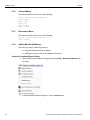
5.1.3 Disconnect Macro................................................................................................................................ 78
5.1.4 Adding New Script Macros ................................................................................................................. 78
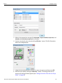
Using the Generation Macros Dialog ................................................................................................ 78
Adding Script Files to the GenScriptMacros Directory ................................................................... 80
5.1.5 Modifying Script Macros..................................................................................................................... 80
5.1.6 Changing the Order of Macro Icons on the Status Bar.................................................................... 80
5.1.7 Deleting User-Defined Script Macros ................................................................................................ 82
5.1.8 Restoring the Default Appearance of the Connect and Disconnect Icons .................................... 82
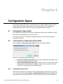
Chapter 6: Configuration Space ..........................................................................83
6.1 Configuration Space Editor ................................................................................................. 83
6.2 Launching the Configuration Space Editor........................................................................ 83
6.2.1 Configuration Space Files .................................................................................................................. 83
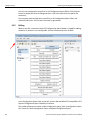
6.2.2 Editing .................................................................................................................................................. 84
6.2.3 BARs Setup.......................................................................................................................................... 87
6.3 Configuration Read and Write ............................................................................................. 88
6.4 Expansion ROM Setup ......................................................................................................... 88
Chapter 7: Address Spaces .................................................................................91
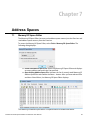
7.1 Memory/IO Space Editor ...................................................................................................... 91
7.2 Memory Regions for Host Emulation.................................................................................. 92
7.3 Using StoreData in Device Mode for Z3 Scripting ............................................................. 92
viii
Summit Z3‐16 PCI Express Multi‐Lane Exerciser User Manual
Teledyne LeCroy
Chapter 8: Updates and Licensing ......................................................................97
8.1 Updating the Exerciser......................................................................................................... 97
8.2 License Keys......................................................................................................................... 97
8.3 License Information.............................................................................................................. 98
Appendix A: Configuration Space Decoding .....................................................99
A.1 Mandatory Definitions ......................................................................................................... 99
A.2 Mandatory Module Functions ............................................................................................. 99
A.2.1 DecodeRegister(offset) ...................................................................................................................... 99
A.2.2 GetSize() ............................................................................................................................................ 100
A.3 Configuration Register Types........................................................................................... 100
A.4 Primitives ............................................................................................................................ 100
A.5 Helper File........................................................................................................................... 101
Appendix B: NVMe Drive Emulation..................................................................103
B.1 NVME Drive Emulation in Windows 7 .............................................................................. 103
B.2 NVME Drive Emulation in Ubuntu Linux 14.10 and Linuxv3.1-rc4 ................................ 107
B.2.1 Hardware Setup for Test Equipment............................................................................................... 108
Appendix C: China Restriction of Hazardous Substances Table ...................117
Appendix D: How to Contact Teledyne LeCroy................................................119
Index:.................................................................................................................. 121
Summit Z3‐16 PCI Express Multi‐Lane Exerciser User Manual
ix
Teledyne LeCroy
x
Summit Z3‐16 PCI Express Multi‐Lane Exerciser User Manual
Chapter 1
Introduction
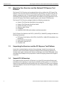
The Teledyne LeCroy Summit Z3‐16 Exerciser™ is an advanced Gen1/2/3 PCI Express verification system capable of generating traffic up to 16 lanes at 8GT/s rates. It blends sophisticated functionality with practical features to speed the development of PCI Express™ IP cores, bridges, switches, add‐in boards, and systems.
This user manual describes the installation and operation of the Summit Z3‐16 Exerciser. It includes a description and examples of the application.
It also describes the installation and operation of the PCI Express Test Platform 16x2.5GT/s / 16x5.0GT/s / 16x8.0GT/s which can be purchased optionally.
1.1
Exerciser Overview
The Summit Z3‐16 is Teledyne LeCroy’s fourth generation exerciser (traffic generator), a critical test and verification tool to assist engineers in developing and improving the reliability of their systems. It adds support for PCI Express at the Gen3 data rate of 8 GT/s.
For system testing the Summit Z3 can be used in a device emulation mode, where the Summit Z3 is directly plugged in to a System Under Test. Hence, the setup is quick and easy.
For device testing the Summit Z3 is used in combination with the PCI Express Test Platform 16x2.5GT/s / 16x5.0GT/s / 16x8.0GT/s which provides host emulation capabilities for Summit Z3. The PCI Express Test Platform has two slots, one for the Summit Z3‐16 Exerciser card and the other for the DUT (Device Under Test). Optionally, for Gen1 and Gen2 host emulation, the Summit Z3 can be used with the passive Teledyne LeCroy PXP‐
100 backplane.
The Summit Z3‐16 builds on the extensive programming and verification test libraries established for Teledyne LeCroy’s PETrainer™ and Summit Z2‐16 PCI Express Exercisers, and provides the user a complete suite of test capability, including the ability to test products to the PCI Express 3.0 specification. When used in combination with the Summit T3‐16 Protocol Analyzer, engineers have a complete test and development environment for PCI Express Gen3 related work.
Summit Z3‐16 PCI Express Multi‐Lane Exerciser User Manual
1
Teledyne LeCroy
1.2
Receiving Your Exerciser and the Optional PCI Express Test Platform
Receiving Your Exerciser and the Optional PCI Express Test
Platform
The Summit Z3‐16 Exerciser can be ordered either with or without the PCI Express Test Platform. You can use the Summit Z3‐16 Exerciser card directly in a system using the AC adapter to power the card. If you purchased the PCI Express Test Platform, you can use the Summit Z3‐16 Exerciser on the PCI Express Test Platform in the provided slot. In this case the PCI Express Test Platform supplies power to the Summit Z3‐16 Exerciser.
The Summit Z3‐16 Exerciser package includes the following components:
Summit Z3‐16 Exerciser identified in the packing list
Summit Z3‐16 Exerciser Quick Start Guide
USB A‐B 2.0 cable, 1.8 meter Ethernet cable, 10 feet AC Adapter
Installation DVD‐ROM with software and documentation
The PCI Express Test Platform 16x2.5GT/s / 16x5.0GT/s / 16x8.0GT/s package includes the following components:
1.3
PCI Express Test Platform 16x2.5GT/s / 16x5.0GT/s / 16x8.0GT/s identified in the packing list
Power cable for Summit Z3
AUX power cables for DUT
AC power cord
Unpacking the Exerciser and the PCI Express Test Platform
Inspect the received shipping container for any damage. Unpack the container and account for each of the system components listed on the accompanying packing list. Visually inspect each component for absence of damage. In the event of damage, notify the shipper and Teledyne LeCroy Corporation. Retain all shipping materials for shipper’s inspection.
1.4
Summit Z3-16 Exerciser
The Teledyne LeCroy Summit Z3‐16 Exerciser is a critical PCIe test and verification tool intended to assist engineers in improving the reliability of their systems. It is a Gen3 PCI Express 16‐lane advanced Exerciser system that can emulate PCI Express root complexes or device endpoints. You can test PCI Express IP cores, semiconductors, bridges, switches, and systems.
2
Summit Z3‐16 PCI Express Multi‐Lane Exerciser User Manual
Exerciser Features
1.5
Teledyne LeCroy
Exerciser Features
The Exerciser has the following features:
Bidirectional x1‐x16, 2.5 GTs to 8.0 GTs generation support for accurate genera‐
tion of PCI Express bus traffic.
Host/Device Emulation Support for allowing design and stress testing.
Link Training and Status State Machine (LTSSM) Testing to exercise LTSSM state transitions for verification.
The latest Z3 Trainer supports CLKREQ# signal that allows for L1 Substrate testing. The older versions of the Z3 Trainer do not have this capability.
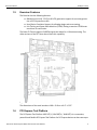
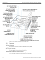
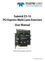
Figure 1.1: Summit Z3-16 Exerciser Front View.
The dimensions of the main board are 16.8 x 13.3cm or 6.6" x 5.25".
1.6
PCI Express Test Platform
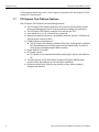
The PCI Express Test Platform 16x2.5GT/s / 16x5.0GT/s / 16x8.0GT/s is a convenient, powerful and flexible PCI Express Test Platform for PCI Express devices at data rates up to Summit Z3‐16 PCI Express Multi‐Lane Exerciser User Manual
3
Teledyne LeCroy
PCI Express Test Platform Features
8 GT/s and lane widths up to x16. It can be used in conjunction with the Summit Z3‐16 to create a DUT environment.
1.7
PCI Express Test Platform Features
The PCI Express Test Platform has the following features:
4
The PCI Express Test Platform accessory to the Summit Z3‐16 Exerciser allows testing and debugging of the PCI Express cards by providing host emulation.
The PCI Express Test Platform supports PCIe rates up to 8 GT/s.
Lane widths of x1, x2, x4, x8 and x16 are supported.
Mechanical support and power is provided for both the Summit Z3‐16 Exerciser and the device under test (DUT).
Flexible Reference Clock options.
The PCI Express Test Platform provides a PCIe clock. Clocking with or without SSC (Spread Spectrum Clocking) can be selected. Additionally, an external clock can be provided through a SMA connector.
Power ON/OFF for the DUT.
DUT power control
DUT power can be switched off without powering PCI Express Test Platform off.
The latest version of the Test Platform supports SRIS and CLKREQ#. Older versions of the Test platform do not have these capabilities. Review the Quick Start Guide for your product to learn how to properly configure the platform.
Summit Z3‐16 PCI Express Multi‐Lane Exerciser User Manual
PCI Express Test Platform Features
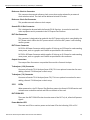
Teledyne LeCroy
Figure 1.2: PCI Express Test Platform 16x2.5GT/s / 16x5.0GT/s / 16x8.0GT/s.
Summit Z3‐16 PCI Express Multi‐Lane Exerciser User Manual
5
Teledyne LeCroy
1.8
Related Reference Documents
Related Reference Documents
For additional information refer to the following documents:
1. PCIe Protocol Suite/Trainer Automation Manual
2. PETrainer Scripting Language Reference Manual
3. Quick Start Guides:
Summit Z3‐16 PCI Express Exerciser
PCI Express Test Platform 16x2.5GT/s /16x5.0GT/s / 16x8.0GT/s
PCI Express Test Platform for Summit™ Z3‐16 Exerciser with CLKREQ# and SRIS Support
Summit Z3‐16 PCI Express Exerciser with CLKREQ# support
6
Summit Z3‐16 PCI Express Multi‐Lane Exerciser User Manual
Chapter 2
Hardware Description
This chapter describes the hardware for the Summit Z3‐16 Exerciser and the PCI Express Test Platform.
2.1
Exerciser System Components
The exerciser has the following components:
2.2
Summit Z3‐16™ Exerciser card
x16 to x1 Edge Adapter
x16 to x4 Edge Adapter
x16 to x8 Edge Adapter
PCIe Protocol Suite software program DVD‐ROM
Host Machine Requirements
The Summit Z3‐16 Exerciser connects to a host machine. Please consult the readme file on the installation DVD for the latest host machine requirements.
2.3
Summit Z3-16 Exerciser
The Summit Z3‐16 is a multi‐lane PCI Express Exerciser (see Figure 2.3 on page 8) designed to assist engineers in improving reliability of their solutions and providing advanced capabilities for stress and compliance testing. All models operate as standalone Exercisers capable of generating and responding to all types of PCI Express transactions. Exercisers also have the ability to create protocol variations and anomalies. Users may create corner case and stress test scenarios to evaluate the robustness of their solutions. By utilizing the error injection feature, engineers can create worst‐case PCI Express traffic scenarios allowing them to validate the error handling capabilities of their solutions.
When used in conjunction with an Analyzer, such as the Teledyne LeCroy Summit T3‐16, a complete expert test and analysis system is created. This integrated solution delivers traffic generation and protocol analysis to assist developers with early validation of designs compliance test preparation with error injection and stress testing.
Summit Z3‐16 PCI Express Multi‐Lane Exerciser User Manual
7
Teledyne LeCroy
Summit Z3‐16 Exerciser
Device Emulation is a standard feature and host emulation is available through the optional PCI Express Test Platform 16x2.5GT/s / 16x5.0GT/s / 16x8.0GT/s.
WARNING: There are no user serviceable parts. For servicing please contact Customer Support at Teledyne LeCroy.
Figure 2.3 Summit Z3-16 Exerciser Front View.
8
Summit Z3‐16 PCI Express Multi‐Lane Exerciser User Manual
Summit Z3‐16 Exerciser
Teledyne LeCroy
Figure 2.4 Summit Z3-16 Exerciser Rear View Showing the UI with LEDs.
The Summit Z3‐16 is a stand‐alone PCI Express Exerciser that can control LTSSM, the Data Link Layer and the Transaction Link Layer to send and receive packets to transfer the data. The Summit Z3‐16 can establish the link from x1 through x16 lane system and change speed from Gen1, Gen2 and Gen3 to exercise LTSSM State Transitions for verification.
2.3.1
User Interface on the Summit Z3-16 Exerciser
The Summit Z3‐16 bracket contains the following interface components:
Summit Z3‐16 PCI Express Multi‐Lane Exerciser User Manual
9
Teledyne LeCroy
Environmental Conditions
2.4
Power On/Off LED
Power socket for the 12V DC Power Connector Power requirement is 100‐240 VAC, 47‐63 Hz universal input for AC Adapter which is included
USB Type B Host Machine Connector
Ethernet port
Environmental Conditions
The environmental condition specifications are:
Operating range from 0 to 40C (32 to 104F), 0 to 90% humidity, non‐con‐
densing
Storage range from ‐10 to 80C (‐4 to 176F)
WARNING: Since the electrical components on the Summit Z3‐16 card are exposed, please use standard ESD practices when handling the board; otherwise, it could be damaged.
2.4.1
Connectors
USB Type B Host Machine Connector
This connector links the Summit Z3‐16 Exerciser to the host machine for the purpose of downloading generation scripts and controlling the behavior of the Exerciser. Note: Use either USB or Ethernet, not both.
Ethernet Port
A 10/100/1000baseT Ethernet connector to the host machine is provided. GIGE Connectivity allows connection to an Ethernet network. This connector links an Exerciser to the host machine for the purpose of downloading generation scripts and controlling the behavior of the Exerciser. Note: Use either USB or Ethernet, not both.
In/Out Connector
This is for future use.
x16 PCIe Edge Connector
The x16 PCIe Edge connector can be adapted to x8, x4 or x1 slots through the use of a Card Reducer Edge Adapter.
10
Summit Z3‐16 PCI Express Multi‐Lane Exerciser User Manual
PCI Express Test Platform 16x2.5GT/s / 16x5.0GT/s / 16x8.0GT/s
2.4.2
Teledyne LeCroy
LEDs
When powered on, the Summit Z3‐16 Exerciser activates user accessible LEDs on the back of the card. TRAIN (training) LEDs
There is a TRAIN LED indicating whether the link is TRAINED or not.
Transmitter and Receiver LEDs
There are 32 LEDs, 16 for Transmitting and 16 for Receiving. These LEDs light up in two colors displaying transmitting or receiving activity.
2.4.3
Green ‐ no errors on the lane
Yellow ‐ the Summit Z3‐16 Exerciser detects errors on this lane
Bus LEDs
There are 3 LEDs indicating the operating speed of 2.5/5.0/8.0 GT/s which is Gen1, Gen2 and Gen3 bus speed.
2.5
PCI Express Test Platform 16x2.5GT/s / 16x5.0GT/s / 16x8.0GT/s
The PCI Express Test Platform 16x2.5GT/s / 16x5.0GT/s / 16x8.0GT/s (see Figure 2.5 on page 12) for the Summit Z3‐16 Protocol Exerciser can be purchased optionally to allow the Summit Z3‐16 Exerciser to act as a host machine, enabling extensive protocol level testing of PCIe devices. It provides a convenient, powerful and flexible PCI Express Test Platform for PCI Express devices at data rates up to 8 GT/s and lane widths up to x16. It has two PCIe slots, one dedicated to the Summit Z3‐16 Exerciser and another for the Device Under Test. The Summit Z3‐16 Exerciser can be conveniently powered by the PCI Express Test Platform using a special power cable, which eliminates the need for an AC power adapter. When purchased with the Summit Z3‐16 Exerciser it provides power to the Summit Z3‐16 Exerciser. The PCI Express Test Platform has a DUT PCIe x16 slot to capture protocol traffic between systems.
In addition, there is a complete Gen3 protocol analyzer interposer built into the platform to enable connectivity with a PCIe analyzer such as the Summit T3 to monitor exerciser traffic. When the PCI Express Test Platform is powered on it provides power to the DUT slot and the Summit Z3 slot. When using the PCI Express Test Platform you can choose a generic internal reference clock or external reference clocking from an external source.
Summit Z3‐16 PCI Express Multi‐Lane Exerciser User Manual
11
Teledyne LeCroy
PCI Express Test Platform 16x2.5GT/s / 16x5.0GT/s / 16x8.0GT/s
Figure 2.5 PCI Express Test Platform Front and Side View.
2.5.1
Connectors
AC Power Connector
The AC Power Connector operates at 100‐240V, 50‐60 Hz, 500W.
DUT PCIe x16 Connector
This slot supplies 3.3V up to 3A and 12V up 5.5A.
The Summit Z3-16 Exerciser Power Connector
A 2‐Pin DC Power Connector for the Summit Z3‐16 is provided.
12
Summit Z3‐16 PCI Express Multi‐Lane Exerciser User Manual
PCI Express Test Platform 16x2.5GT/s / 16x5.0GT/s / 16x8.0GT/s
Teledyne LeCroy
Reference Clock In Connector
This connects the external reference clock source that can be selected by an external clock selection switch. The clock will be delivered to both PCIe slots.
Reference Clock Out Connector
This provides external reference clock output.
Summit Z3-16 Slot Connector
This is designed to be used with the Summit Z3‐16 Exerciser. It can also be used with other equipment and is powered via the PCI Express Test Platform.
DUT Slot Connector
This connector is designed to be used with the DUT. Power to this slot is controlled by the DUT Power switch. When the DUT power switch is off all the DUT power is off including auxiliary power.
DUT Power Connector
DUT 6‐Pin DC Power Connector which supplies 12 Volts up to 6.25 Amps for cards needing more power, such as a graphic card. Cables are provided for this connector.
DUT 8‐Pin DC Power Connector which supplies 12 Volts up to 12.5 Amps for cards needing more power, such as a graphic card. Cables are provided for this connector.
Output Connectors
Two output iPass Connectors are provided for use with a Protocol Analyzer.
To Analyzer (15:8) Connector
Connects to Summit T3‐16 Analyzer (lanes 15:8). This is an optional connection for users adding a Summit T3‐16 Analyzer to their setup.
To Analyzer (7:0) Connector
Connects to Summit T3‐16 Analyzer (lanes 7:0). This is an optional connection for users adding a Summit T3‐16 Analyzer to their setup.
2.5.2
LEDs
When powered on, the PCI Express Test Platform powers the Summit Z3‐16 Exerciser and activates user accessible controls and LEDs on the back of the card.
DUT PRSN LED
There are four DUT PRSN LEDs that show the state of the DUT x1, x4, x8 and x16 present signals.
Power Monitor LED
There are two LEDs to monitor power to the lower PCIe slot indicating 3.3V or 12V.
Summit Z3‐16 PCI Express Multi‐Lane Exerciser User Manual
13
Teledyne LeCroy
PCI Express Test Platform for Summit™ Z3‐16 Exerciser with CLKREQ# and SRIS Support
Aux DUT Power LED
There are two LEDs to monitor the auxiliary power to the DUT indicating 3.3V or 12V.
2.5.3
Switches and Buttons
System Power On/Off Switch
This switch is used to power the PCI Express Test Platform on and off.
SSC Switch
This switch is used to turn Spread Spectrum Clocking on and off only when using the internal reference clock. When using an external reference clock, this switch has no effect.
Reference Clock Switch
The Reference Clock Selector switch is used to select the internal or external clock on the PCI Express Test Platform. The PCI Express Test Platform is capable of taking an external reference clock source, or it can generate its own clock. The clock is delivered to both PCIe slots.
DUT Power Switch
This switches the DUT power, both auxiliary and slot power, on and off. Reset Bus Button
There is a Reset Bus button provided on the platform to emulate the PE Reset.
2.6
PCI Express Test Platform for Summit™ Z3-16 Exerciser with
CLKREQ# and SRIS Support
Teledyne LeCroy's PCI Express 3.0 Test Platform for the Summit Z3‐16 Protocol Exerciser provides a convenient, powerful and flexible test platform for PCI Express devices at data rates up to 8 GT/s and lane widths up to x16.
The Test Platform allows the Summit Z3‐16 Exerciser to act as a host system, enabling extensive protocol‐level testing of PCIe® devices. In addition, there is a complete Gen3 protocol analyzer interposer built into the platform complete with iPass connectors for up to x16 lane support.
For use as a host emulator, the Summit Z3‐16 Exerciser is plugged into the dedicated PCIe slot and connected to the power source provided by the Test Platform. The DUT is plugged into the PCIe x16 slot, and connected to either the 6‐pin or the 8‐pin 12V power sources provided on the Test Platform.
Switches on the platform allow the user to select internal or external reference clocks separately for the Summit Z3‐16 and DUT, SSC, SRIS, CLKREQ# and power for the DUT. Connectors on the platform include two PCIe x16 slots, dual Ref Clock IN and OUT, dual iPass connectors for connection to a Teledyne LeCroy protocol analyzer such as the 14
Summit Z3‐16 PCI Express Multi‐Lane Exerciser User Manual
PCI Express Test Platform for Summit™ Z3‐16 Exerciser with CLKREQ# and SRIS Support
Teledyne LeCroy
Summit T3‐16, and DC power connectors (2‐pin for the Summit Z3‐16, and the choice of 6‐pin or 8‐pin for the DUT).
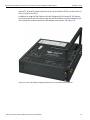
In addition to using the Test Platform with the Teledyne LeCroy Summit Z3‐16, the user can connect two of their own devices and use the Test Platform as a PCIe backplane and as an interposer to capture protocol traffic between the systems. See Figure 2.6.
Figure 2.6 PCIe Test Platform Supporting Summit Z3-16 with SRIS and CLKREQ#
Summit Z3‐16 PCI Express Multi‐Lane Exerciser User Manual
15
Teledyne LeCroy
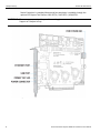
2.6.1
PCI Express Test Platform for Summit™ Z3‐16 Exerciser with CLKREQ# and SRIS Support
Connections
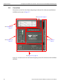
Connections to the PCIe Test Platform Supporting the Summit Z3-16 Exerciser with SRIS and
CLKREQ# can be seen in Figure 2.7.
See Figure 2.8 on page 17
See Figure 2.12 on
page 19
See Figure 2.11 on
page 19
See Figure 2.9 on
page 17
See Figure 2.10 on page 18
Figure 2.7 Connections to PCIe Test Platform Supporting Summit Z3-16 Exerciser with CLKREQ#
and SRIS
16
Summit Z3‐16 PCI Express Multi‐Lane Exerciser User Manual
PCI Express Test Platform for Summit™ Z3‐16 Exerciser with CLKREQ# and SRIS Support
Teledyne LeCroy
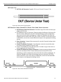
DUT Under Test
DUT PCIe x16 Connector: Supplies 3.3 V up to 3 A and 12 V up to 5.5 A.
Figure 2.8 Device Under Test Connector
DUT Reference Clocks, Summit Z3-16 Clocks, iPass Cable, Power Connection
DUT Reference Clock Out Connector: Provides a copy of the clock currently sup‐
plied to the DUT slot.
DUT Reference Clock In Connector: Connects external reference clock source for the DUT. Clock is delivered to the DUT slot depending on switch configuration, see switch selection tables and diagram. To drive the 100 MHz clock input the following sources can be used: CML, HCSL, LVPECL and LVDS. If your clock source is differential, connect the unused differential output to the appropriate loading resistor.
iPass Connectors: 2 output iPass connectors for use with Protocol Analyzer (such as Summit T3‐16)
Summit Z3‐16 Power Connector: 2‐pin DC power connector to provide power for Summit Z3‐16 (supplies 12v up to 6.25A)
Summit Z3‐16 Reference Clock Out Connector: Provides a copy of the clock cur‐
rently supplied to the Summit Z3 slot
Summit Z3‐16 Reference Clock In Connector: Connects external reference clock source for the Summit Z3‐16. Clock is delivered to the Summit Z3‐16 slot depending on switch configuration. See switch selection tables and diagram. To drive the 100 MHz clock input the following sources can be used: CML, HCSL, LVPECL and LVDS. If your clock source is differential, connect the unused differ‐
ential output to the appropriate loading resistor.
Figure 2.9 Clock, Power and Data Connectors
Summit Z3‐16 PCI Express Multi‐Lane Exerciser User Manual
17
Teledyne LeCroy
PCI Express Test Platform for Summit™ Z3‐16 Exerciser with CLKREQ# and SRIS Support
Switches and LEDs
Reset Bus Button: Generates PERST# reset.
DUT PRSNT LEDs: 4 LEDs indicate whether x1, x4, x8, or x16 DUT is plugged in.
CLKREQ Selector Switch: Allows for CLKREQ# to turn off the clocks when enabled.
Summit Z3‐16 PCIe x16 Slot: Powered by Test Platform, supplies 3.3V up to 3A and 12V up to 5.5A. Can be used with other equipment.
SSC Selector Switch (for Z3‐16): When using the internal reference clock, turns Spread Spectrum Clocking (SSC) on or off. If using external reference clock, the switch has no effect.
Z3‐16 Reference Clock Selector Switch: Selects the internal or external clock. Clock is delivered to Summit Z3 slot.
Z3‐16 Slot Power Monitor LEDs: 2 LEDs monitor power to Summit Z3 slot.
Figure 2.10 Switches and LEDs
Reference Clock for DUT (SRIS), DUT Power Connectors, DUT Switches, DUT LEDs
18
SRIS Control Switch for DUT: Select Common (both slots use the same clock) or Separate (each slot uses an independent clock).
SSC Selector Switch (for DUT:) When using the internal reference clock, turns Spread Spectrum Clocking (SSC) on or off. If using external reference clock, the switch has no effect.
DUT Reference Clock Selector Switch: Selects the internal or external clock. Clock is delivered to DUT slot.
DUT Power Selector Switch: The DUT Power switch controls power to the DUT slot.
DUT Power Monitor LEDs: 2 LEDs monitor power to the DUT: 3.3 V or 12 V.
DUT 6‐pin DC Power Connector: Supplies 12 V up to 6.25 A for graphics cards (cable provided). DUT 8-pin DC Power Connector: Supplies 12 V up to 12.5 A for graphics cards (cable
provided).
Summit Z3‐16 PCI Express Multi‐Lane Exerciser User Manual
PCI Express Test Platform for Summit™ Z3‐16 Exerciser with CLKREQ# and SRIS Support
Teledyne LeCroy
Figure 2.11 Aux DUT Power Connectors, LEDs, Clock Switches
Clock Logic Diagram
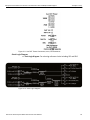
Clock Logic Diagram: For selecting reference clocks including SSC and SRIS.
Figure 2.12 Clock Logic Diagram
Summit Z3‐16 PCI Express Multi‐Lane Exerciser User Manual
19
Teledyne LeCroy
2.7
PCI Express PXP‐100B Test Platform 16x2.5GT/s / 16x5.0GT/s
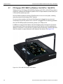
PCI Express PXP-100B Test Platform 16x2.5GT/s / 16x5.0GT/s
Teledyne LeCroy's PCI Express PXP‐100B Test Platform 16x2.5GT/s / 16x5.0GT/s provides a convenient, powerful and flexible test platform for PCI Express devices at data rates up to 5 GT/s and lane widths up to x16.
The Test Platform allows the Summit Z3‐16 Exerciser to act as a host system, enabling extensive protocol‐level testing of PCIe® devices.
For use as a host emulator, the Summit Z3‐16 Exerciser is plugged into any slot and connected to an external power source. The DUT is plugged into the remaining available slot, the PXP‐100B provides the necessary power up to 75W per slot.
In addition to using the Test Platform with the Teledyne LeCroy Summit Z3‐16, the user can connect two of their own devices and use the Test Platform as a PCIe backplane by adding an interposer or using the built in midbus footprint and using a midbus probe will allow an analyzer to capture protocol traffic between the devices. See Figure 2.13.
Figure 2.13 PXP-100B PCI Express Test Platform
20
Summit Z3‐16 PCI Express Multi‐Lane Exerciser User Manual
PCI Express PXP‐100B Test Platform 16x2.5GT/s / 16x5.0GT/s
2.7.1
Teledyne LeCroy
Connections, LEDs and Switches
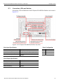
Connections, LEDs and Switches to the PCI Express PXP‐100B Test Platform can be seen in Figure 2.14.
Figure 2.14 PCI Express PXP‐100B Test Platform Top View
Clock Configuration
Clock Input Specification
Parameter
Specification
J1000
Selected Clock
Peak to peak voltage level
0.3 V (Min), 1 V (Max)
Short
External
Input interface level accepted
LVPECL, LVDS, LVHSTL, SSTL, HCSL
Open
Internal
Nominal frequency
100 MHz
Clock Output Specification
Parameter
Specification
Peak to peak voltage level
0.3 V
Interface level
LVDS
Nominal frequency
100 MHz
Summit Z3‐16 PCI Express Multi‐Lane Exerciser User Manual
21
Teledyne LeCroy
PCI Express PXP‐100B Test Platform 16x2.5GT/s / 16x5.0GT/s
22
Summit Z3‐16 PCI Express Multi‐Lane Exerciser User Manual
Chapter 3
Installation
This chapter provides instructions to install the Summit Z3‐16 Exerciser, the PCI Express Test Platform 16x2.5GT/s / 16x5.0GT/s / 16x8.0GT/s and software installation.
3.1
Software Installation
This section describes the PCIe Protocol Suite installation on your host machine. The PCIe Protocol Suite operates on systems using the Windows 8 (x86 and x64), Windows Server 2012 (x64), Windows 7 (x86 and x64), Windows Server 2008R2 (x64), Windows XP (x86). The latest Service Pack available for the Windows OS in use is required. It is recommended that you use one of the supported 64‐bit Windows versions listed above as they allow using more RAM than the 32‐bit ones.
Once you have installed the software, you can begin traffic generation after following the steps in this chapter. 3.1.1
Installing the PCIe Protocol Suite software
PCIe Protocol Suite software operates all of Teledyne LeCroy’s PCI Express protocol Analyzer and Exerciser products:
The PCIe Protocol Suite software is installed on a Microsoft® Windows®‐based host machine and serves as the interface for the Exerciser and/or Analyzer.
To install the Protocol Software Suite on the host machine: 1. Insert the Installation DVD‐ROM into the DVD drive on the host machine.
2. The installation automatically starts setup, unless Auto Run is off. In that case, select the DVD‐ROM from “My Computer” and click Setup.
3. After the warning to close all other programs and before starting the installation, the Install component selection opens.
4. Select components for installation.
5. Click Next to complete the installation.
6. To start the application, launch the PCIe Protocol Suite program from the Start menu: Start > Programs > LeCroy > PCIe Protocol Suite > PCIe Protocol Suite
Summit Z3‐16 PCI Express Multi‐Lane Exerciser User Manual
23
Teledyne LeCroy
Setting Up the Summit Z3‐16 Exerciser using a USB Connection
Note: You can also download the software from the Teledyne LeCroy website and install it following steps 2 through 6 above.
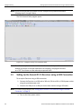
The PCIe Protocol Suite program opens.
Figure 3.15: Teledyne LeCroy PCIe Protocol Suite
Note: The software may be used with or without the Exerciser or Analyzer. When used without an Exerciser or Analyzer attached to the computer, the program functions as a CATC Trace Viewer to view and analyze captured traffic. 3.2
Setting Up the Summit Z3-16 Exerciser using a USB Connection
To set up the Exerciser using a USB connection: 1. Connect the Exerciser to a 100‐volt to 240‐volt, 50 Hz to 60 Hz, 120 W power outlet using the provided power cord. 2. Connect the USB port to a USB port on the host machine using a USB cable.
Note: To connect using Ethernet, see “Setting Up the Summit Z3‐16 Exerciser using an Ethernet Connection” on page 25.
3. Turn on the front power switch. 24
Summit Z3‐16 PCI Express Multi‐Lane Exerciser User Manual
Setting Up the Summit Z3‐16 Exerciser using an Ethernet Connection
Teledyne LeCroy
Note: At power‐on, the Exerciser initializes itself in approximately five seconds and performs an exhaustive self‐diagnostic that lasts about forty seconds. The results are reflected by messages on the Summit T3‐16 LCD display. If the LCD display indicates failure, call Teledyne LeCroy Customer Support for assistance. 4. Follow the Microsoft® Windows® on‐screen Plug‐and‐Play instructions for the automatic installation of the Exerciser as a USB device on your analyzing host machine. (The required USB drivers are installed on your system by the PCIe Protocol Suite application software installation.)
Click Finish when you see the message that says “Windows has finished installing the software that your new hardware requires” and the file has been installed in your host machine. 3.3
Setting Up the Summit Z3-16 Exerciser using an Ethernet
Connection
1. Connect the Exerciser to a 100‐volt to 240‐volt, 50 Hz to 60 Hz, 120 W power outlet using the provided power cord. 2. Connect the Summit Z3 Exerciser to the network. Note: To connect using USB, see “Setting Up the Summit Z3‐16 Exerciser using a USB Connection” on page 24.
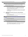
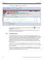
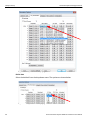
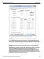
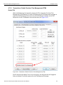
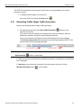
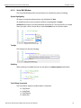
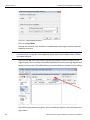
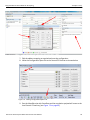
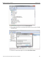
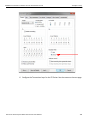
3. Turn on the front power switch. Note: At power‐on, the Exerciser initializes itself in approximately five seconds and performs an exhaustive self‐diagnostic that lasts about forty seconds. 4. After you have installed the PCIe Protocol Suite application software, perform the following procedure to connect to a Summit Z3‐16 Exerciser in the local network. Select the Setup > All connected devices… menu in the PCIe Protocol Suite application software to display the Exerciser Devices dialog.
Summit Z3‐16 PCI Express Multi‐Lane Exerciser User Manual
25
Teledyne LeCroy
Setting Up the Summit Z3‐16 Exerciser using an Ethernet Connection
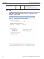
Figure 3.16: Exerciser Devices Dialog
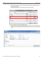
The PCIe Protocol Suite application software fills the list with devices that are connected over USB or discovered on the Ethernet network. The discovery mechanism works only within one network subnet. If a Summit Z3 is connected to the network on a different subnet, you can manually add the subnet to the list by clicking the Add Device button and specifying the IP address.
The Summit Z3 devices in the list are marked:
Locked: Some other client on the network is already connected to that device
Ready to connect: Available for connection
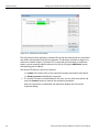
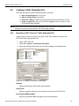
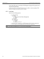
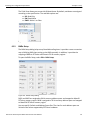
1. If a Summit Z3 device is marked Ready To Connect, you can select that device and press the Connect button to execute the connection procedure. After the connection is established, the application displays the Connection Properties dialog.
26
Summit Z3‐16 PCI Express Multi‐Lane Exerciser User Manual
Setting Up the Summit Z3‐16 Exerciser using an Ethernet Connection
Teledyne LeCroy
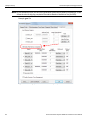
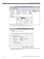
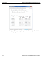
Figure 3.17: Connection Properties Dialog
2. Select an option:
Automatically connect to the device: When the application is started or when the named device is added to the network while the PCIe Protocol Suite applica‐
tion is running on this computer, the software will try to connect to the named device. Ask if I want to connect to the device: When the application is started or when the named device is added to the network while the PCIe Protocol Suite applica‐
tion is running on this computer, the software will display a message box allow‐
ing you to connect to the named device. Take no action: When you start the application or when you want to add the named device to the network while the PCIe Protocol Suite application is running on this computer, you must connect manually to use the named device. Note: When you close the application on this computer (or you perform a manual disconnect), the application disconnects from the device. 3. Press OK in the Connection Properties dialog.
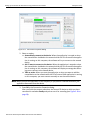
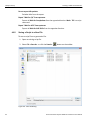
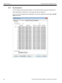
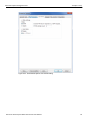
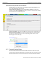
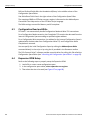
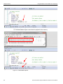
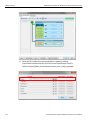
After you finish the connect procedure, the Summit Z3 device to which you have connected is marked as Ready and you can use it for recording (see Figure 3.18 on page 28).
Summit Z3‐16 PCI Express Multi‐Lane Exerciser User Manual
27
Teledyne LeCroy
Adding Devices Manually
Figure 3.18: Analyzer Devices Dialog Showing all Connected Devices
Note: To disconnect from a device, display this dialog, select the device, and click the Disconnect button.
Note: As of version PCIe Protocol Suite version 7.34, the software is able to access a Summit exerciser via VPN solutions that require explicit bindings to PPP adapters that they create.
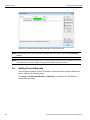
3.4
Adding Devices Manually
You can locate and add a Summit Z3 located in a Ethernet subnet using the Add Device button. Perform the following steps:
Click Setup ‐> All Connected Devices ‐> Add Device ‐> to display the Add Ethernet Attached Device dialog.
28
Summit Z3‐16 PCI Express Multi‐Lane Exerciser User Manual
Adding Devices Manually
Teledyne LeCroy
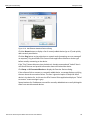
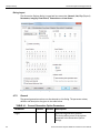
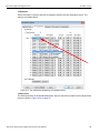
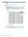
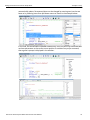
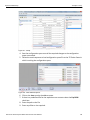
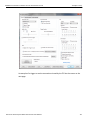
Figure 3.19: Add Ethernet Attached Devices Dialog
Click the Recent button to display a list of recently added devices (up to 15) and quickly add a recently used device.
Click the Ping button to ping a device as a network node (prompting an error message if no response). Ping also allows PCIe Protocol Suite application to detect a device type before actually connecting to the device. If the "Ping" feature discovers that the device is already connected and "locked" then it will inform the user and provide information about who locked the device.
Click Setup ‐> All Connected Devices to display the Exerciser Devices dialog .
If the software fails to connect to a manually added device, a message displays notifying the user about the connection failure. The user is given the option to keep the failed device in the device list, in this case the PCIe Protocol Suite application displays a "Failed to connect" status message in grey.
Square brackets for IP addresses are used for manually added devices to easily distinguish them from auto‐discovered devices. Summit Z3‐16 PCI Express Multi‐Lane Exerciser User Manual
29
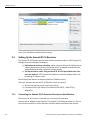
Teledyne LeCroy
Setting Up the Summit Z3‐16 Exerciser
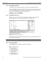
Figure 3.20: Add Ethernet Attached Devices Dialog
3.5
Setting Up the Summit Z3-16 Exerciser
The Summit Z3‐16 Exerciser can test both the host and device sides of a PCI Express link through the use of two types of adapters:
Motherboards and host controllers: When using the Summit Z3‐16 Exerciser as a device emulator, the Summit Z3‐16 Exerciser is an adapter card that fits into motherboards and other slotted PCI Express devices.
PCI Express add‐on cards: Using a Summit Z3‐16 PCI Express Multi‐Lane Exer‐
ciser User Manual. A PCI Express Test Platform is a box‐like adapter with a slot for testing PCI Express cards.
Both of these test devices can be purchased from Teledyne LeCroy.
There are two ways the Summit Z3‐16 Exerciser can be connected:
3.5.1
Directly inserted into a slot in the host machine
Connected via the PCI Express Test Platform 16x2.5GT/s / 16x5.0GT/s / 16x8.0GT/s
Connecting the Summit Z3-16 Exerciser Directly to a Host Machine
The Summit Z3‐16 Exerciser is inserted into a slot in the host machine. Connect the AC adapter to the Exerciser. The Summit Z3‐16 Exerciser powers on. Do not turn the host machine on till the Exerciser initializes which could take a few minutes.
30
Summit Z3‐16 PCI Express Multi‐Lane Exerciser User Manual
Setting Up the Summit Z3‐16 Exerciser
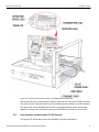
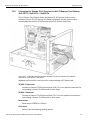
3.5.2
Teledyne LeCroy
Connecting the Summit Z3-16 Exerciser to the PCI Express Test Platform
16x2.5GT/s / 16x5.0GT/s / 16x8.0GT/s
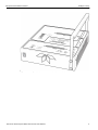
The PCI Express Test Platform allows the Summit Z3‐16 Exerciser to act as a host emulation system. The PCI Express Test Platform enclosure has two slots on top to accommodate the Summit Z3‐16 Exerciser and a DUT (Device Under Test).
Figure 3.21: Connecting the Summit Z3-16 Exerciser via the PCI Express Test Platform
16x2.5GT/s / 16x5.0GT/s / 16x8.0GT/s.
Hardware enclosure with a slot on top for accommodating a PCI Express card.
TX/RX 8‐15 Connector
Connects to Summit T3‐16 Exerciser (lanes 15:8). This is an optional connection for users adding a Summit T3‐16 Exerciser to their setup.
TX/RX 0‐7 Connector
Connects to Summit T3‐16 Exerciser (lanes 7:0). This is an optional connection for users adding a Summit T3‐16 Exerciser to their setup.
Reset button
Reset asserts PERST# for > 250 ms.
Clock Select
Selects from the following clocking options:
Summit Z3‐16 PCI Express Multi‐Lane Exerciser User Manual
31
Teledyne LeCroy
Setting Up the Summit Z3‐16 Exerciser
Ext: a user supplied reference via the RefCLK SMA connector.
Int: an internal supplied 100MHz reference clock.
Int SSC: an internal supplied 100MHz Spread Spectrum Clock.
Power Select switch
When the DUT Power is turned on 3.3V and 12V is supplied to the DUT slot along with AUX power. Additional Auxiliary Power can be used by connecting to the 6‐pin (75W) or 8‐pin (150W) connectors.
Power LED
Lights when the PCI Express Test Platform is powered on.
Perform the following steps to connect the Exerciser to the PCI Express Test Platform:
1. Insert the Summit Z3‐16 Exerciser card in the Summit Z3 slot on the PCI Express Test Platform.
2. Connect the 12V DC power cable from the PCI Express Test Platform (labeled Z3 Power Cable) to the Summit Z3‐16 Exerciser. 3. Insert a DUT in the DUT slot. Connect AUX power if necessary.
4. Select correct reference clock source using clock selection switches.
5. Connect Summit T3 analyzer to Analyzer connectors to monitor traffic between Summit Z3 and DUT (optional).
6. Connect the AC power cable to the PCI Express Test Platform 16x2.5GT/s / 16x5.0GT/s / 16x8.0GT/s. Turn the PCI Express Test Platform 16x2.5GT/s / 16x5.0GT/
s / 16x8.0GT/s switch on to power the enclosure. The Exerciser's green power LED lights turns on for approximately one minute while the Exerciser performs self‐
diagnostics.
7. Using the Ethernet or USB cables connect the Summit Z3‐16 Exerciser card to the host machine.
8. Open the PCIe Protocol Suite application on the host machine. The Exerciser is now ready for traffic generation. 32
Summit Z3‐16 PCI Express Multi‐Lane Exerciser User Manual
Chapter 4
Traffic Generation
A traffic generator can emulate PCI Express™ root complexes and endpoint devices. Traffic generation can be used to transmit known errors, allowing you to observe how your device handles faulty link conditions.
After the Summit Z3‐16 Exerciser and DUT have been cabled and powered on, you can test the setup by generating some traffic. The following steps show how to configure the Exerciser to generate a Link Training sequence.
4.1
Theory of Operation
4.1.1
Overview
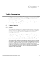
The Exerciser offers two mechanisms for implementing traffic generation: scripts, in which any type of traffic can be defined and executed, and the Generation Options dialog box, which offers a collection of PCI Express specific behaviors that can be enabled for automatic generation of traffic. Using scripts, packets can be transmitted consecutively, with specific timing, or with event‐based pauses between them. This allows the Exerciser to act as a pattern generator with PCI Express‐specific formatting and transmission rates. However, creating traffic that emulates real devices with relatively complex protocol behaviors using a simple pattern generator is quite complicated. Certain behaviors such as ACK policies, and flow control require concurrent processing. This is where the automated features become useful.
The Exerciser includes a collection of automated traffic generation circuits that commonly exist in other PCI Express devices. These circuits include ACK/NAK generation, flow control management, a LTSSM, replay buffers, and transaction timers. What makes the Exerciser unique and so useful is that each of these behaviors can be individually modified or disabled. This allows the user to perform operations that might not otherwise be possible using an off the shelf PCI Express device. This can be particularly useful when doing compliance or fault recovery testing.
Summit Z3‐16 PCI Express Multi‐Lane Exerciser User Manual
33
Teledyne LeCroy
4.1.2
LTSSM Control
Starting Point
When the Exerciser first powers up, it is at electrical idle on all lanes. The link is not trained, but the LTSSM is enabled and waiting for a command to train the link. To begin communication with a PCI Express device, Link training must occur, but first the generation settings must be set. This involves setting the Link parameters such as link width, polarity inversion, and lane reversal, through the Generation Options dialog. Note: Setting the options in the Generation Options dialog has no effect on the Exerciser behavior until the first script is executed. In fact, each time a script is executed, these behaviors are reprogrammed to the Exerciser and the behaviors are modified accordingly.
4.2
LTSSM Control
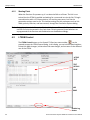
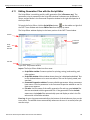
The LTSSM Control button on the Summit Z3 Exerciser status toolbar can be pressed to open the LTSSM Control dialog. In this dialog, you can initiate speed switches, initiate link width changes, initiate select link state changes, and run tests on the different arcs of the LTSSM.
ACTIVE
TEST
TEST DETAILS
PANE
LOG PANE
Figure 4.1: LTSSM Control Menu.
34
Disable Log Button
Summit Z3‐16 PCI Express Multi‐Lane Exerciser User Manual
LTSSM Control
4.2.1
Teledyne LeCroy
Link Speed Control
The Summit Z3‐16 Exerciser supports traffic generation at three speeds: 2.5, 5.0 and 8.0 GT/s. The link speed control shows the current link speed and has buttons to initiate speed switches to corresponding speeds. When you press a speed control button, the Summit Z3‐16 Exerciser initiates a speed switch for the speed indicated on that button. The link may not change speed if the speed switch operation is unsuccessful.
The speed switch buttons may be enabled/disabled based on the speed configuration settings in the exerciser’s Generation Options settings. For example, if you set up a Summit Z3‐16 Exerciser as a Gen2 capable device in the Generation Options, the Gen3 (8.0GT/s) speed switch button will be disabled.
4.2.2
Link Width Control
The Summit Z3‐16 Exerciser supports traffic generation at five different link widths: x1, x2 x4, x8 and x16. The link width control shows the current link width and has buttons to initiate link width changes to corresponding widths.
When you press a link width control button, the Summit Z3‐16 Exerciser will initiate a link width change for the link width indicated on that button. The link width after the operation may not match the desired link width if the operation is unsuccessful.
The link width buttons may be enabled/disabled based on the link width configuration settings in the exerciser’s Generation Options settings. For example, if you set up the Summit Z3‐16 as a x4 device in the Generation Options, the x8 and x16 link width change buttons are disabled.
4.2.3
Link State Control
The Summit Z3 Exerciser currently supports direction to the following nine link states: Detect, Recovery, Hot Reset, Disabled, L0, L0S, Loopback (Compliance Rx=0), Loopback (Compliance Rx=1), Clear Loopback, Direct to L1 (Device Emulation mode only) and Direct to L2 (Device Emulation mode only). The link state control shows the current state of the PCI Express Link. For example, when the Link is down, it shows Detect. You can direct the Summit Z3‐16 into one of the stated nine specific LTSSM states by selecting the desired state in the “Go to Link State” drop down box and pressing the Apply button. The exerciser will then receive instructions to transition into the selected state. The resulting link state after such a transition may be different than the selected state based on the link. For example, if you direct the Summit Z3‐16 LTSSM into a Recovery state when the link is at L0, the Summit Z3‐16 will initiate a recovery sequence, but after the recovery the link should get back to the L0 state.
The intermediate link states, such as Polling and Configuration, are handled by the Summit Z3‐16 exerciser. After receiving a link transition command to L0 / connect, the LTSSM is alive, the exerciser will keep the Link active just as any other PCI Express device would, this includes handling of the Recovery states and subsequent retraining events.
Summit Z3‐16 PCI Express Multi‐Lane Exerciser User Manual
35
Teledyne LeCroy
LTSSM Control
When the Summit Z3‐16 is directed to any of the low power states, it should be brought out to L0 first before directing it to another low power state. For example, If the Summit Z3 is in L1, it can not be directed to L0s immediately, you need to first direct it to L0 and from there to L0s.
Note: If the device under test (DUT) does not support Loopback mode, the Summit Z3 may not correctly transition out of Loopback state and a Link Reset may be required.
4.2.4
LTSSM Arc Tests
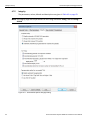
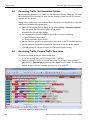
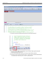
The Summit Z3‐16 Exerciser has been developed to allow for testing of the different arcs of the LTSSM. This list of tests is displayed in the LTSSM Arc Tests in the left pane. When you select a test from the test list, its information is displayed in the adjacent right panel. The information is in the form as follows:
Test: The name of the test.
Test Description: A brief description of the test.
PreRequisites: The expected state that this test is starting from.
Test Scenario: Explains the details of what the test will perform.
Expected DUT State Transitions: The LTSSM states that the Device Under Test is going through.
These tests have different prerequisites that need to be met in order to be run. Tests that have their prerequisites met and that are ready to be run are displayed in black. Tests that do not have their prerequisites met will be grayed out in the list of tests and you will not be able to run them if you select them. In order to run tests that do not have their prerequisites met, you can view the prerequisites and/or the description of the test by clicking on that specific test. From there, you can manipulate the link speed/width/state of the exerciser to match the prerequisites so that the test is enabled to run.
For example, as shown in the LTSSM Control Dialog, the Summit Z3‐16 is linked up at 2.5GT/s (Gen1) so the first test is ready to be run but the second and third tests are grayed out since they require 5.0GT/s (Gen2) and 8.0GT/s (Gen3) speeds.
To run a test, select the test and click Run. The LTSSM state transitions from the test will be displayed in the LTSSM Log (the bottom pane).
4.2.5
LTSSM Log
After issuing a speed change, link width change, link state transition, and/or running any LTTSM arc test, the LTSSM state transitions that occurred will be displayed in the LTSSM Log. This log will accumulate the state transitions from different run tests and the results from commands issued from the controls. You can clear this log by clicking the Clear Log button and you can also save the log as a text file for future reference by clicking on the Save Log button. Clicking the Save Log button will prompt open the save file dialog. Clicking on the Disable Log button will turn off the logging of data.
36
Summit Z3‐16 PCI Express Multi‐Lane Exerciser User Manual
Exerciser Control Bar
Teledyne LeCroy
Running an LTSSM arc test will clear the logged transitions in the Summit Z3‐16 before the test runs to ensure that all the test transitions are recorded. Clearing the log will also clear any logged transitions in the Summit Z3‐16.
Note: Reading the entire log takes time and may be unnecessary in some cases. Disable Log option will prevent the application from reading the trainer log.
4.3
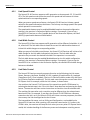
Exerciser Control Bar
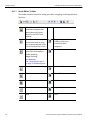
Figure 4.2: Exerciser Control Bar.
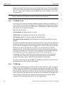
The following icons are displayed in the Exerciser Control Bar.
The Start Traffic Generation button starts traffic generation of a currently loaded generation script. Before starting the generation it saves all the changes to the script file. If you start a new script that does not yet have a name, the Save As dialog opens to save the .peg file (see “Generating Traffic: Begin Traffic Generation” on page 67).
The Stop Traffic Generation button stops generation script execution.
The Resume Traffic Generation button resumes generation script execution if it was stopped.
Connect and Disconnect buttons. When you click the Connect button it executes a connect script. It directs the Summit Z3‐16 LTSSM into L0 state. It uses the device parameters, such as supported speed and link width, from the Generation Options Click on the Disconnect button to disconnect. It directs the Summit Z3‐16 into Detect state.
You can switch to a different speed by clicking on the Go to 2.5, 5.0, 8.0 buttons. Pressing these buttons will initiate a speed switch. The link may not change speed if the speed switch operation is unsuccessful. Summit Z3‐16 PCI Express Multi‐Lane Exerciser User Manual
37
Teledyne LeCroy
Exerciser Control Bar
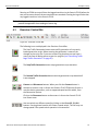
The Write and Read Address Space buttons. The Summit Z3‐16 is capable of emulating device memory spaces. Using these buttons you can load data into the different memory spaces and read data from each of the memory spaces.You can also access these by clicking Generate > Write Address Space and Generate > Read Address Space. See Figure 4.3 on page 38 and Figure 4.4 on page 38.
Figure 4.3: Write Address Space.
Figure 4.4: Read Address Space.
The LTSSM control button brings up another dialog box that allows more options for real time control of the Z3 Trainer.
38
Summit Z3‐16 PCI Express Multi‐Lane Exerciser User Manual
Generating Traffic
Teledyne LeCroy
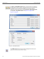
The following icon may be displayed in the Top tool bar and can also be located in the Setup menu option (see figure below). The Setup Generation Options button enables you to configure the generation options (see “Generation Options Dialogs Overview” on page 43).
Figure 4.5: Top Tool Bar.
4.4
Generating Traffic
To generate traffic, open or create a traffic generation file (*.peg) and then run it. Figure 4.6: Open Trace File.
When the file is opened, it appears in the CATC Trace window looking like a CATC Trace file. To run the file, click the Start Generating Traffic
Summit Z3‐16 PCI Express Multi‐Lane Exerciser User Manual
button.
39
Teledyne LeCroy
Script Execution
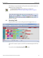
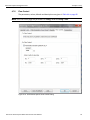
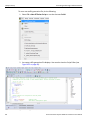
To create or edit a .peg file, use the Script Editor.
Figure 4.7: Script Editor.
The Script Editor is a text‐editing tool that can be opened by clicking
File>New from the menu bar.
or selecting Alternatively, the traffic generation file can be created by exporting the data from a CATC Trace into a traffic generator file. 4.5
Script Execution
As mentioned above, each time a script is executed, the configuration settings for the Summit Z3‐16 Exerciser are reprogrammed. When the Start generation button is pressed, the script is uploaded to the Exerciser hardware and executed immediately. The progress of the script can be tracked in the Exerciser Control Bar at the bottom of the screen. Subsequent executions of the same script do not require upload of the script to the Summit Z3‐16 Exerciser, however, as mentioned above, the generation options are still reprogrammed.
Script execution can be throttled using Wait commands inserted directly into the script. Waits can be time based, require receipt of certain packet types, or can even require User input from the GUI.
After the script is complete, any enabled PCI Express behaviors, such as SKIP insertion, Flow control, and ACK generation, continue. This allows you to run multiple scripts, one after another, without interrupting the Link state.
40
Summit Z3‐16 PCI Express Multi‐Lane Exerciser User Manual
Creating a Traffic Generation File
4.6
Teledyne LeCroy
Creating a Traffic Generation File
There are four ways to create a traffic generation script file:
Export an existing trace to a script file
Save an existing script to a new file
Select File > New to create a new and empty script file that contains no text.
Create an empty file using an OS shell (with .peg extension) and open it with PCIe Protocol Suite software.
Note: Please refer to the PETrainer Scripting Language Reference Manual for a comprehensive list of available commands and structures for PCIe and storage protocols.
4.6.1
Exporting a CATC Trace to a Traffic Generation File
A simple way to create a script file is to open a CATC Trace and then to export the CATC Trace data to a generation file:
1. Open a CATC Trace file.
2. Select File > Export > to Generator File Format. 3. Select the desired options from the File Export dialog box as shown below.
Figure 4.8: File Export As Generator Format Dialog.
Direction
Selects the direction of the traffic to be exported.
From and To
Selects a range for exporting. You can export all or part of the CATC Trace.
Do not export hidden packets
Ignores any packets hidden through the various hide options.
Summit Z3‐16 PCI Express Multi‐Lane Exerciser User Manual
41
Teledyne LeCroy
Creating a Traffic Generation File
Do not export Idle packets
Excludes Idles from the export.
Export “Wait for Cpl” from upstream Exports all Wait for Completions from the opposite direction. Wait = TLP is a script command.
Export “Wait for ACK” from upstream Exports all Wait for ACK DLLPs from the opposite direction.
4.6.2
Saving a Script to a New File
To save a script file as a generation file:
1. Open an existing script file.
2. Select File > Save As… or click the Save As button on the toolbar.
Figure 4.9: Save As Dialog.
42
Summit Z3‐16 PCI Express Multi‐Lane Exerciser User Manual
Generation Options Dialogs Overview
Teledyne LeCroy
3. Navigate to the desired folder and type a new file name where you want to save the current script, then click the Save button:
When the Save As command completes, the newly created script is displayed.
Note: The Save As dialog box includes the option Save all included files. This option causes the software to save any Include files that have been included in the script. The Included files are saved to the same directory as the traffic generation file.
4.6.3
Creating a New Empty Generation File
To create a generation file from scratch see the next section.
4.7
Generation Options Dialogs Overview
The Generation Options dialog box is used to configure settings of the device. If there are additional devices, you can control the settings separately of each device. Once the settings are changed you can save them as a default. When the application is launched the next time, the default settings are loaded.
These options are also used in a traffic generation script (for example, Config = General or Config = Link). This dialog duplicates the Config script command and is provided as a convenient alternative means of setting this command in the script. Note: Generation Options together with Config Script commands define the Summit Z3 behavior as a device. Some configuration changes may require a link reset to ensure correct system operation. For example, changing lane reversal settings or changing available flow control values after the link has been established will cause problems with the link.
Note: The Generation Options dialog is subordinate to the script itself, so script commands override options selected in this dialog box. 4.7.1
Opening the Dialog
To open the Generation Options dialog (see Figure 4.10 on page 44) select Setup > Generation Options or click
the Generation Options button
Summit Z3‐16 PCI Express Multi‐Lane Exerciser User Manual
. 43
Teledyne LeCroy
Generation Options Dialogs Overview
Dialog Layout
The Generation Options dialog is organized into seven tabs: General, Link, Phy (Physical) Parameters, Integrity, Flow Control, Transactions and Low Power.
Figure 4.10: Generations Options Dialog.
4.7.2
General
The general generation options can be selected on this dialog. The parameter values, defaults and description are given in the table below.
TABLE 4.1: General Generation Option Parameters
Parameter
Target
44
Values
Default
Description
Specifies the generation platform. The choice affects some of the options presented in the Generation Options dialogs.
Summit Z3‐16 PCI Express Multi‐Lane Exerciser User Manual
Generation Options Dialogs Overview
Teledyne LeCroy
Data Rate 2.5 GT/s
Data Rate 5.0 & 2.5 GT/s Data Rate 8.0, 5.0, 2.5 GT/s
Selection
2.5GT/s
Specifies advertised data rate.
Link Width
1
2
4
8
16
1
Specifies the link width. Based on the Link Width you choose by selecting the radio button the settings on the Invert Polarity and Skew are enabled.
Disable Scrambling Tx
Yes
No
No
Select to disable scrambling of the data that the Summit Z3‐16 is transmitting (applies only to Gen1 and Gen2 data rates).
Invert Polarity Tx
From 0 to 15
Inverts the polarity of the selected lanes that the Summit Z3‐16 is transmitting.
Invert Polarity Rx
Disabled for Summit Z3‐16 as it automatically detects polarity of incoming data.
Emulation Role
Host or Device
Host
Select to specify Host or Device emulation.
Reverse Lanes (TX/RX)
Yes
No
No
Select this option to emulate a host/device with reversed lanes. This option will reverse both RX and TX lanes to emulate a reversed link and test the DUT tolerance. If the link is actually reversed this option will cause the Z3 to not train properly.
Follow Lane Reversal
Yes
No
No
When set, the Summit Z3‐16 responds to lane reversal requests from the DUT.
When cleared, the Summit Z3‐16 Trainer does not follow the lane reversal protocol.
Note: In this case the link may not be able to train.
Use External Reference Clock
Yes
Yes
No
When unchecked, the Summit Z3 uses an on board clock (no SSC) that allows operation when there is no reference clock provided.
When checked, the Z3 uses the reference clock from the bus. This allows for independent clocking operation when using the Summit Z3 Test Platform.
Summit Z3‐16 PCI Express Multi‐Lane Exerciser User Manual
45
Teledyne LeCroy
Generation Options Dialogs Overview
Analyzer Control
4.7.3
Yes
No
No
No
Gives you the option to:
Start recording when generation starts.
Stop recording when generation stops.
Link
The Link Generation Options dialog allows you to set up the link options. The parameters, values, defaults and descriptions are given in Table 4.2, “Link Generation Option Parameters,” on page 47 below.
Figure 4.11: Generations Options Link Dialog.
46
Summit Z3‐16 PCI Express Multi‐Lane Exerciser User Manual
Generation Options Dialogs Overview
Teledyne LeCroy
TABLE 4.2: Link Generation Option Parameters
Parameter
Values
Default
Description
Enable Automatic SKIP Generation
Enable Automatic SKIP Generation
Skip Timer in symbols
1360
Gen 3 in blocks
370
Disable Auto TX Presets
FTSCount
Periodic timer that controls sending of SKIP ordered sets at specific intervals. The timer’s value is measured in number of symbols for Gen1/Gen2 and in 130 bit blocks for Gen3.
Disables auto transmit preset values
0 to 255
255
Number of FTS ordered sets required (as sent in TS)
1.0 Spec
Both versions of the specification are supported so you can choose either of them.
Link Training Parameters
Gen3 Specification version
0.7, Oct 09
0.7, Jun 09
0.71 Spec
1.0 Spec
Skip Equalization in Link Training
The Summit Z3‐16 will skip all equalization stages during Gen3 training. Skip EQ in Training Phase 2, 3
The Summit Z3‐16 will skip phase 2 and 3 equalization stages during Gen3 training.
Enable Autonomous Speed Change
Enables Autonomous Speed change support.
Disable Auto Tx Presets
Disables Autonomous Speed change support.
Summit Z3‐16 PCI Express Multi‐Lane Exerciser User Manual
47
Teledyne LeCroy
4.7.4
Generation Options Dialogs Overview
Phy Parameters
This tab displays the physical parameters of transmission and receiving. It allows you to select equalization parameters for transmitting and receiving lanes. You can control lane parameters individually, or set them together by selecting the Set All Lanes check box.
Figure 4.12: Generations Options Phy Parameters Displaying Default Values.
48
Summit Z3‐16 PCI Express Multi‐Lane Exerciser User Manual
Generation Options Dialogs Overview
Teledyne LeCroy
TX Emphasis
Select the Preset, Preshoot and the De‐emphasis values from the drop‐down menu. The options are shown below.
Figure 4.13: Phy Parameters Displaying TX Emphasis Values.
TX Advertised
The Advertised value is the broadcasted value. You can also select a value from the drop‐down menu as shown in Figure 4.14 on page 50.
Summit Z3‐16 PCI Express Multi‐Lane Exerciser User Manual
49
Teledyne LeCroy
Generation Options Dialogs Overview
Figure 4.14: Phy Parameters Displaying TX Advertised Values.
RX DC Gain
Select the decibels from the drop‐down menu. The options are shown below.
Figure 4.15: Phy Parameters Displaying RX DC Gain Values.
50
Summit Z3‐16 PCI Express Multi‐Lane Exerciser User Manual
Generation Options Dialogs Overview
Teledyne LeCroy
RX CTLE Gain
Select values from 0 to 15 from the drop‐down menu. RX Advertised
The Advertised value is the broadcasted value. You can also select a value from the drop‐down menu as shown in Figure 4.16 on page 51.
Figure 4.16: Phy Parameters Displaying RX Advertised Values.
Summit Z3‐16 PCI Express Multi‐Lane Exerciser User Manual
51
Teledyne LeCroy
4.7.5
Generation Options Dialogs Overview
Integrity
The parameters, values, defaults and descriptions are given in Table 4.3 on page 53.
Note: The Integrity page sets the parameters for two Config commands: Config = TLP and Config = AckNak Figure 4.17: Generations Options Integrity Dialog.
52
Summit Z3‐16 PCI Express Multi‐Lane Exerciser User Manual
Generation Options Dialogs Overview
Teledyne LeCroy
TABLE 4.3: Integrity Generation Option Parameters
Parameter
Values
Default
Comment
Auto
Ack
Nak
Disable
Auto
Auto ‐ The Summit Z3‐16 will send Ack or NAK according to the PCIe specification
ACK/NAK Policy
Disable automatic ACK/NAK DLLP generation
Always ACK received TLP packets
Ack‐ The Summit Z3‐16 will Ack all incoming TLP packets. Using this option will improve ACK latency of the Summit Z3‐16, but does not guarantee reliable data transmission.
Always NAK received TLP packets
NAK ‐ The Summit Z3‐16 will NAK all incoming TLP. Automatic ACK/NAK DLLP generation for received TLP packets (default)
Disable. The Summit Z3‐16 will not send any Ack or NAK packets automatically. Ack and NAK packets can still be generated using a script.
TLP Policy
Automatically generate TLP sequence numbers
Yes
No
Yes
If not set, overrides automatic generation of the TLP sequence number and uses user‐
defined value of the field in the Packet=TLP commands. This option overrides any sequence numbers specified in the script.
Automatically generate TLP LCRC
Yes
No
Yes
If not set, overrides automatic generation of LCRC and uses user‐defined value of the field in the Packet=TLP commands. This option overrides any LCRC specified in the script.
Automatically retransmit TLPs that were NAKed or on replay timer expiration
In symbols
Off
3150
Timeout in TLP transmitter path that counts time since last Ack or Nak DLLP is received. If set, automatically retransmit TLPs that were NAKed or on replay timer expiration.
User defined Replay Timer
In symbols
Off
3150
If set, enable the user to define the Replay Timer. Summit Z3‐16 PCI Express Multi‐Lane Exerciser User Manual
53
Teledyne LeCroy
Generation Options Dialogs Overview
Automatically retrain Yes
the link when No
number of retransmitted TLPs is 4
Yes
If set, enable automatic retraining of the link in case the number of retransmitted TLP is 4. Valid only when AutoRetransmission is set.
Tag generation policy for non-posted TLPs
54
Disable automatic tag generation
Yes
No
No
Prevents the Exerciser from automatically inserting a tag. Tags are a sub‐field of the transaction ID field.
When auto tag insertion is enabled, the tag field is only modified for non‐posted transactions such as CfgRd, CfgWr, and MemRd.
Use lower 5‐bit of Tag field. Zero out higher 3 bits
Yes
No
No
The Summit Z3‐16 will automatically generate 5‐bit TLP tags.
Use 8‐bit of Tag field
Yes
No
No
The Summit Z3‐16 will automatically generate 8‐bit TLP tags.
Summit Z3‐16 PCI Express Multi‐Lane Exerciser User Manual
Generation Options Dialogs Overview
4.7.6
Teledyne LeCroy
Flow Control
The parameters, values, defaults and descriptions are given in Table 4.4 on page 56.
Note: The Flow Control page sets parameters for Config = FCTx and Config = FCRx.
Figure 4.18: Generations Options Flow Control Dialog.
Summit Z3‐16 PCI Express Multi‐Lane Exerciser User Manual
55
Teledyne LeCroy
Generation Options Dialogs Overview
TABLE 4.4: Flow Control Generation Option Parameters
FCRx Parameter
Values
Default
Comment
Yes
No
Yes
When not set, the TLPs are being sent without the regard of how many credits are available.
This option prevents TLP transmission if insufficient credits are available.
In ns (rounded to nearest 8)
Off
4200
When enabled, allows automatic updating of these DLLPs.
This option enables a periodic timer that controls sending of UpdateFC DLLPs. You should leave timer and credit values to defaults for correct behavior.
Tx Flow Control
Do not send TLP packet if credit amount is insufficient
Rx Flow Control
Periodically schedule UpdateFC DLLP
Initial Credits to Advertise
PH
0 to 255
1
Posted Request Headers
NPH
0 to 255
1
Non‐Posted Request Headers
CPLH
0 to 255
1
Completion Headers
PD
0 to 4095
1024
Posted Request Data Payload
NPD
0 to 4095
1
Non‐Posted Request Data Payload
CPLD
0 to 4095
1024
Completion Data Payload
Note: Currently the Summit Z3‐16 Exerciser does not support processing for nullified TLPs in the receiver path. This test scenario should be avoided.
56
Summit Z3‐16 PCI Express Multi‐Lane Exerciser User Manual
Generation Options Dialogs Overview
4.7.7
Teledyne LeCroy
Transactions Device Emulation
Select Device in the General tab to display the Host Memory Regions pane in the Transactions tab. When in Device Emulation mode, the Summit Z3‐16 can automatically process incoming Configuration, Memory and IO read and write requests. This tab allows you to configure these options.
Figure 4.19: Generations Options Transactions Dialog - Device Emulation.
Summit Z3‐16 PCI Express Multi‐Lane Exerciser User Manual
57
Teledyne LeCroy
Generation Options Dialogs Overview
TABLE 4.5: Transactions Generation Option Parameters - Device Emulation
Parameter
Values
Default
Comment
Automatically handle Configuration Read and Write TLP transactions
Yes
No
No
If set, automatically handles Configuration Read and Write TLP transactions. For Configuration Read transactions, Completion TLP contains the data read from the internal Configuration Space according to the specified register address. For Configuration Write transactions, the internal Configuration Space is updated at the address with the data from Configuration Write TLP, and Configuration Write Completion is returned. This option enables Read and Write access to 4‐KB configuration space.
Automatically handle Memory and IO Read and Write TLP transactions
Yes
No
No
If set, automatically handles Memory and IO Read and Write TLP transactions. For Memory and IO Read transactions, Completion TLP contains the data read from the internal Memory/IO Address Space according to the specified address. For Memory and IO Write transactions, internal Memory/IO Address Space is updated at the address with the data from TLP.
Automatically handle Expansion ROM
Yes
No
No
If set, automatically handles system Reads from Expansion ROM, using the base address programmed by the system in the Expansion ROM Base Address register in the configuration space of Device Emulation. The driver data could be programmed in the Expansion ROM address space using the Address Space Write functionality.
4.7.8
Transactions Host Emulation
When in Host Emulation mode, up to three physical memory regions can be defined to be automatically handled by the Summit Z3 (see Figure 4.20 on page 59).
58
Summit Z3‐16 PCI Express Multi‐Lane Exerciser User Manual
Generation Options Dialogs Overview
Teledyne LeCroy
Figure 4.20: Generations Options Transactions Dialog - Host Emulation.
Select Host in the General tab to display the Host Memory Regions pane in the Transactions tab.
One 64‐bit and two 32‐bit regions can be specified. If a region is selected, the Physical Address for the start of the region has to be provided as well as the length in 4 KB blocks.
Read Completion Boundary for the Host (Root Complex) emulation can be specified as 128 or 64 bytes, as defined by the PCI Express specification.
Maximum Payload Size in bytes can be specified as 128, 256, 512, 1024, 2048, 4096.
When Host Memory Regions are selected, they are accessible for reading and writing by Write and Read Address Space buttons (see Exerciser Control Bar) as well as by AddressSpace = Write and AddressSpace = Read script commands. When the Device Under Test reads memory locations in the physical address range defined by one of the enabled regions, the data written there prior to that (from the application/script or by the device itself over PCI Express) is going to be returned.
Summit Z3‐16 PCI Express Multi‐Lane Exerciser User Manual
59
Teledyne LeCroy
Generation Options Dialogs Overview
Examples of using Host Memory Regions can be found in the SampleFiles\Z3‐
16TrainerScripts\NVMe_HostEmulation folder of the PCIe Protocol Suite software.
4.7.9
Transactions Fast Memory Completer
TABLE 4.6: Transactions Fast Memory Completer Parameters
60
Parameter
Values
Default
Comment
Enable Fast Memory Completer
Yes
No
No
If set, enables the high‐performance memory completer functionality. Region
‐‐Not Set‐‐
Mem_64
Mem_32A
Mem_32B
Fixed_64
Fixed_32
‐‐Not Set‐‐
A Region is a range of addresses in PCI Express memory space, which the high‐performance memory completer handles using a defined policy. There are two region types:
• The first type is defined by the fixed address location, such as Fixed_32 and Fixed_64, and can be used for both Device and Host Emulation.
• The second type is defined by the specific device memory space, such as Mem_64, Mem_32A, and Mem_32B, specified in the BAR setup in the Configuration Space Editor, and can be used only for Device Emulation. The supplied Address is really the Offset from the beginning of the corresponding memory space. The actual address is calculated by the Summit Z3‐16 Trainer when the BARs are configured.
When a region is enabled, all Write data to the address range is consumed at high speed and discarded. All completion data for read requests is filled according to the rules specified by the PldGrowth and PldSeed parameters.
Six regions are currently available for the fast memory completer. FastMemoryCompleter must be set to enable the Region.
Summit Z3‐16 PCI Express Multi‐Lane Exerciser User Manual
Generation Options Dialogs Overview
Teledyne LeCroy
Address/
Offset (hex)
32‐bit Address/
Offset
64‐bit Address/
Offset
32‐bit 0x000000
00
If the corresponding Region is set, based on the region type, this field is a 32‐bit Offset for Mem_32A and Mem_32B, 64‐
bit Offset for Mem_64, 32‐bit Address for Fixed_32, and 64‐bit Address for Fixed_64. The corresponding Region must be set to enable the Address/Offset.
Length (in 4‐KB blocks)
0 to 1,048,576
0
If the corresponding Region is set, this field specifies the length of the address range in 4‐
kilobyte blocks, starting from the address/
offset, in the Address/Offset field, to which the fast memory completer responds.
The corresponding Region must be set to enable Length.
PldGrowth
Fixed Byte
Fixed DWord
Incr Byte
Incr DWord
Fixed Byte
If the corresponding Region is set, this field specifies the expected payload format.
Fixed Byte and Fixed DWord specify a payload of a byte or dword pattern consisting of PldSeed. Incr Byte and Incr DWord specify a payload of incrementing bytes or dwords starting from zero. The corresponding Region must be set to enable PldGrowth.
PldSeed (hex)
8‐bit value
10‐bit value
0
If the corresponding Region is set and PldGrowth is set to Fixed Byte or Fixed DWord, this field species the byte value repeated for PldGrowth of Fixed Byte or the 10‐bit dword value for PldGrowth of Fixed DWord. For other types of PldGrowth, this field is set to zero. The corresponding Region and PldGrowth must be set to enable Pldseed. Generate ECRCs Yes
No
No
Enable if memory completions need to have ECRC appended. The TD bit will be asserted for the completions generated by the fast memory completer.
Note: In Device emulation mode, the current MaxPayload size set in configuration space will be used by completions from both firmware memory space and FastCompleter.
Summit Z3‐16 PCI Express Multi‐Lane Exerciser User Manual
61
Teledyne LeCroy
Generation Options Dialogs Overview
Note: In Host emulation mode, the RCB set in generation options will be used by completions. Z3 will follow the rules for aligning completion boundaries based on MaxPacket size (and RCB).
Example .gen File
Figure 4.21: Selecting Options to Enable Fast Memory Completer.
62
Summit Z3‐16 PCI Express Multi‐Lane Exerciser User Manual
Generation Options Dialogs Overview
4.7.10
Teledyne LeCroy
Transactions: Enable Precision Time Management (PTM)
Enable PTM
When enabled during Host emulation, directs the Z3 to respond to Precision Time Management (PTM) Request TLPs with PTM Response and PTM ResponseD messages as required. PTM Response will be sent for the first PTM Request received, and a PTM ResponseD for each PTMRequest received thereafter (see Figure 4.22).
Figure 4.22: Transactions: Enable Precision Time Management (PTM)
The Z3 maintains the Master Time in 4ns increments, and will generate the Propgation Delay and Master Time fields required for the PTM ResponseD message.
Summit Z3‐16 PCI Express Multi‐Lane Exerciser User Manual
63
Teledyne LeCroy
Generation Options Dialogs Overview
If the Enable PTM option is unchecked, all PTM Request messages will be ignored and no response will be generated.
In device emulation, the Enable PTM selection has no effect. In device emulation PTM Request messages may be generated via scripting.
4.7.11
Low Power
Select from the following options:
L1 State Settings
Modes ASPM (Active State Power Management)
PCIPM
Enable L1
L1 Sub States
Disable
Select L1_1 or L1_2
Send PM ACKs in response to L1 ASPM requests (Host Emulation mode only)
Enter a value for PM Ack/Nak Count (Host Emulation mode only)
Note: L1 sub states are enabled only for Z3 Trainers with CLKREQ# support.
64
Summit Z3‐16 PCI Express Multi‐Lane Exerciser User Manual
Generation Options Dialogs Overview
Teledyne LeCroy
Figure 4.23: Generations Options Low Power Dialog.
Summit Z3‐16 PCI Express Multi‐Lane Exerciser User Manual
65
Teledyne LeCroy
4.8
Generating Traffic: Set Generation Options
Generating Traffic: Set Generation Options
Before beginning generation, set options in the Generation Options dialog box. The steps below describe how to change the most common settings in order for the Z3 Trainer to operate with any device.
Change other options only if you need a different behavior from the default or if you are experiencing problems during operation.
1. Open the Generation Options dialog box by selecting Setup > Generation Options from the menu. The Generation Options dialog opens. By default the General page displays. 2. Set the generation direction based on type of device you are emulating.
Host Emulation: Select Host
Device Emulation: Select Device
3. Set the maximum speed to be advertised by the trainer in the TS Data Rate options.
4. Set the maximum link width to attempt by the trainer in the Link Width options.
5. Click OK to apply all changes and close the Generation Options dialog.
4.9
Generating Traffic: Prepare Traffic Generation
To prepare for traffic generation, follow these steps:
1. If it is not running, start the PCIe Protocol Suite™ software.
2. Open an existing script file or create a new script. For example, open the traffic generation file Exported.peg by selecting File > Open from the menu. The following packets display in the main window (see Figure 4.24 on page 66).
Figure 4.24: Opening an Existing Script File.
66
Summit Z3‐16 PCI Express Multi‐Lane Exerciser User Manual
Generating Traffic: Begin Traffic Generation
Teledyne LeCroy
The CATC Trace window shows the type of traffic that is to be generated in the current generation session.
3. If needed, make changes to the script file, then save the file by clicking the Save button
4.10
.
Generating Traffic: Begin Traffic Generation
Perform the following steps to begin traffic generation: 1. Start generation by clicking the Start Traffic Generation
button on the Exerciser Control Bar. This action causes the software to download the script to the device. After the download completes, the device starts executing the script. As the script executes, the Exerciser Control Bar displays the script's progress. The Current script position field displays the command description and CATC Trace packet number currently being generated.
Script Progress
Script Position
Note: Script execution can be terminated at any time by clicking the
Stop Generation
button on the toolbar.
If a Wait command is executed where the Display parameter is specified, the user‐defined text is displayed. If a wait=user script command is executed, the script pauses until you click the
Resume Generation button Summit Z3‐16 PCI Express Multi‐Lane Exerciser User Manual
on the toolbar.
67
Teledyne LeCroy
Generating Traffic: Begin Traffic Generation
To run a new traffic generation file, do the following:
1. Select File > New PETrainer Script or use the shortcut Ctrl+N.
2. An empty traffic generation file displays. You can also view the Script Editor (see Figure 4.25 on page 68).
Figure 4.25: Empty Traffic Generation File.
68
Summit Z3‐16 PCI Express Multi‐Lane Exerciser User Manual
Editing Generation Files with the Script Editor
4.11
Teledyne LeCroy
Editing Generation Files with the Script Editor
The Script Editor is an editing tool for traffic generation files (<filename>.peg). The generation script is presented in the Script Edit window. Parameters are presented in menus and text boxes in the Command Properties window in the right‐hand portion of the Script Editor. To launch the Script Editor: click the Script Editor button
on the toolbar or right‐click the CATC Trace window and choose Edit as Text from the pop‐up menu.
The Script Editor window displays in the lower portion of the CATC Trace window.
Toolbar
Command
Properties
Window
Script
Editor
Window
File Tabs
Figure 4.26: Script Editor Window.
Layout: The Script Editor divides into four areas:
Script Editor toolbar: Presents options for printing, saving, bookmarking, and other options. Script Edit window: Main window where the script is displayed and edited. Text in this window behaves as in most text editors. Text can be copied, pasted, and searched.
Command Properties window: Presents editable parameters. Many parameters have menus. Click the parameter in the Command Properties window to see if a down‐arrow appears.
File tabs: Lists the name of the traffic generation file and any open Include files that are associated with the generation file. If the generation file has Include statements, the Include files automatically open and display as tabs in the File tabs section of the Editor window.
Error Log: An error log opens automatically at the bottom of the window any time a script error occurs. The window closes automatically whenever the error is corrected, after you save the script.
Summit Z3‐16 PCI Express Multi‐Lane Exerciser User Manual
69
Teledyne LeCroy
4.11.1
Editing Generation Files with the Script Editor
Script Editor Toolbar
The toolbar contains buttons for saving your edits, navigating, searching and other functions.
Save. Saves your edits and immediately updates the setting bars and Frames shown in the CATC Trace window.
70
Go to Trace View.
Causes trace view to bring the currently selected script line to the top of the screen.
Toggle Bookmark. Allows markers to be set or removed to aid in navigation.
View Options. Opens a menu with three options:
Enable Outlining
Toggle Outlining
Line Numbers.
See “View Options Menu” on page 74 for descriptions.
Next Bookmark.
Cut.
Previous Bookmark.
Copy.
Clear All Bookmarks.
Paste.
Find.
Undo.
Replace. Find and replace.
Redo.
Print.
Summit Z3‐16 PCI Express Multi‐Lane Exerciser User Manual
Editing Generation Files with the Script Editor
4.11.2
Teledyne LeCroy
Script Edit Window
The Script Edit Window offers several features to simplify the process of editing.
Syntax Highlighting
All known commands and parameters are highlighted in blue.
All predefined values and command modifiers are highlighted in brown.
Intellisense prompts for known predefined values/literals. This functionality is invoked when you type = after a known key or select List values from the Context menu.
Tooltips
The Tooltips look like the following:
Outlining
When outlining is enabled the user has the option to collapse/expand code blocks:
Text Editing Commands
The Script Editor supports standard editor commands:
Copy/Paste
Undo/Redo
Find/Replace
Bookmarks
Summit Z3‐16 PCI Express Multi‐Lane Exerciser User Manual
71
Teledyne LeCroy
Editing Generation Files with the Script Editor
Synchronized Scrolling with the CATC Trace Window
You can navigate from the generation code window to the corresponding place in the CATC Trace representation, and vice versa.
From the CATC Trace window, right‐click the first cell in a packet in the CATC Trace window and select Go to Script Editor from the pop‐up menu. The Script Editor window then repositions to the corresponding code.
From the script editor, right‐click some code within the Script Editor window and select Position Trace view on packet x from the pop‐up menu (where x is a packet number). The CATC Trace window repositions to the corresponding packet number (see the following figure on the next page).
4.11.3
Command Properties Window
The Command Properties window lists all possible parameters for the current script command and all values for the parameters currently defined in this command. Entering parameters/values within the Edit window causes the Command Properties window to 72
Summit Z3‐16 PCI Express Multi‐Lane Exerciser User Manual
Editing Generation Files with the Script Editor
Teledyne LeCroy
automatically update. Parameters/values can be changed by entering text into the text boxes or by selecting items from pull‐down menus as shown in the example below.
In this case, the edit window is updated automatically. If the current script command does not have parameters or the current cursor position is outside of any script command, then a generic prompt is displayed in the window:
Summit Z3‐16 PCI Express Multi‐Lane Exerciser User Manual
73
Teledyne LeCroy
4.11.4
Editing Generation Files with the Script Editor
Script Editor File Tabs
At the bottom of the Script Editor window is the name of the open generation file. If there are Include statements in the generation file that link it to other generation files, these files automatically open and display as tabs at the bottom of the window. You can click the tabs to toggle between the open generation files.
4.11.5
Script Editor Error Log
Whenever you create a scripting error, a log opens at the bottom of the application window. When the error is corrected, the window automatically closes.
Errors: Marked by red squares.
Warnings: Marked by yellow squares.
Double‐clicking an error in the error log causes the cursor in the edit window to move to where the error was detected.
Note: You cannot run the script if it has syntax errors.
4.11.6
View Options Menu
The View Options button displays a menu with these options: 74
Summit Z3‐16 PCI Express Multi‐Lane Exerciser User Manual
Editing Generation Files with the Script Editor
Teledyne LeCroy
Enable Outlining: Adds an expandable/collapsible tree structure to the left side of the Script Editor showing the hierarchical relationships of the script lines.
Show Line Numbers: Adds line numbers to the left side of the Script Editor window.
Show Tooltips: Allows tooltip pop‐ups, which provide descriptions of script keywords when cursor mouses over a keyword.
Toggle Outlining: Toggles the outline tree between collapsed and expanded states.
Summit Z3‐16 PCI Express Multi‐Lane Exerciser User Manual
75
Teledyne LeCroy
76
Editing Generation Files with the Script Editor
Summit Z3‐16 PCI Express Multi‐Lane Exerciser User Manual
Chapter 5
Macros
5.1
Macros
You can add buttons to the Status bar at the bottom of the window (and add commands to the Generate menu) to run traffic generation macros on the Exerciser. After a macro script has been defined and assigned to a button the on the Status bar, the macro can be run by clicking the macro button with the mouse or selecting the macro name from the Generate menu.
5.1.1
Default Macros: Connect and Disconnect
By default, the PCIe Protocol Suite™ software includes two macros, Connect and Disconnect. These buttons execute macros for creating and breaking a connection between the Exerciser and a DUT.
The buttons are on the Status bar when Exerciser hardware is present. The commands are also on the Generate menu:
Summit Z3‐16 PCI Express Multi‐Lane Exerciser User Manual
77
Teledyne LeCroy
5.1.2
Macros
Connect Macro
The default code for this macro is the following:
Config
Link =
Wait =
Link =
Wait =
Link =
5.1.3
= General {TrainerReset = 1}
Detect
500
L0
500
InitFC
Disconnect Macro
The default code for this macro is the following:
Config = General {TrainerReset = 1}
Link = Detect
5.1.4
Adding New Script Macros
There are two ways to add script macros:
Using the Generation Macros dialog
Adding script files to the GenScriptMacros directory.
Using the Generation Macros Dialog
1. Open the Generation Macros dialog by selecting Setup > Generation Macros from the menu.
2. In the Generation Macros dialog box, click the New button.
78
Summit Z3‐16 PCI Express Multi‐Lane Exerciser User Manual
Macros
Teledyne LeCroy
3. Within Script properties area specify script name, script comment, script icon, and whether or not to show script icon on a toolbar.
4. Create a new icon for the script by clicking Edit Icon... button. The Edit Generation Macro Icon dialog displays.
5. Using the tools provided, paint the icon for new script macro and then press OK.
6. Edit the script code by clicking the Edit code... button. The dialog closes and an empty script editing window appears (see “Editing Generation Files with the Script Editor” on page 69).
Summit Z3‐16 PCI Express Multi‐Lane Exerciser User Manual
79
Teledyne LeCroy
Macros
7. Type the script code and press the Save button. The script macro and icon are saved in the GenScriptMacros directory located under the PCIe Protocol Suite directory (for example, Program Files\CATC\PCIe Protocol Suite\GenScriptMacros).
8. Close the script window. The new macro script button automatically appears on the Status bar at the bottom of the window. Clicking this button causes the Exerciser to execute the script.
Adding Script Files to the GenScriptMacros Directory
The second way to add a new script macro is to copy an existing script file in the GenScriptMacros directory. 1. Copy a script file into the GenScriptsMacros directory located under the PCIe Protocol Suite directory (for example, Program Files\CATC\PCIe Protocol Suite\GenScriptMacros).
2. Switch to the PCIe Protocol Suite application. You see that a new icon has been automatically added for the script file to the Status bar at the bottom of the window. The default icon is assigned to the new script macro and the file name is used as a script name.
5.1.5
Modifying Script Macros
To modify a macro assigned to a button:
1. Select Setup > Generation Macro from the menu to open the Generation Macros dialog for modifying, creating, and deleting macros:
Name: Name of Macro
Comment: Descriptive comment so you can remember what the macro does
Icon: Currently assigned button for the macro.
Show icon on the toolbar: If checked, places the icon on the Status bar.
Edit Code: Opens a dialog for editing the macro script.
2. Select the macro to be modified.
3. Within the Script properties area, modify the script name, script comment, script icon, and whether or not to show script icon 4. To edit script code, press the Edit code... button. The Generation Macros dialog closes and the Script Editing window appears, showing current code for the selected script macro. Note: If the Generation Script Editor pane does not appear, click .
5. Modify the script code and press the Save button . 6. Close the script window. The macro has now been modified.
5.1.6
Changing the Order of Macro Icons on the Status Bar
To change the order of script macro icons on the Status bar:
1. Open Generation Macro Scripts dialog by selecting Setup > Generation Macros.
80
Summit Z3‐16 PCI Express Multi‐Lane Exerciser User Manual
Macros
Teledyne LeCroy
2. Click the Up and Down buttons to change the order of the script macros.
3. Close the dialog. The button order is changed.
Summit Z3‐16 PCI Express Multi‐Lane Exerciser User Manual
81
Teledyne LeCroy
5.1.7
Macros
Deleting User-Defined Script Macros
To delete a script macro:
1. Open the Generation Macro Scripts dialog by selecting Setup > Generation Macros.
2. Select the macro you want to delete and press the Delete button:
All deleted scripts and icons are removed from GenScriptMacros directory. A backup copy is stored in the GenScriptMacros\Deleted directory.
Note: You cannot delete the Connect and Disconnect script macros. 5.1.8
Restoring the Default Appearance of the Connect and Disconnect Icons
You can restore the default appearance of the Connect and Disconnect icons by clicking the Restore button.
1. Open the Generation Macro Scripts dialog by selecting Setup > Generation Macros.
2. Select the macro you want to restore and press the Restore button.
82
Summit Z3‐16 PCI Express Multi‐Lane Exerciser User Manual
Chapter 6
Configuration Space
For Device Emulation, PETrainer™ provides features to emulate Address Spaces of a PCI Express device, including Configuration, Memory, and IO spaces. The following two chapters describe how to set up, configure, and manipulate Address Spaces.
6.1
Configuration Space Editor
The Configuration Space Editor allows the Configuration Space to be modified on a field‐
by‐field basis using hexadecimal or binary format.
The editor supports PCI‐compatible Configuration Spaces and PCI Express enhanced Configuration Spaces.
6.2
Launching the Configuration Space Editor
Selecting Tools > Configuration Space Editor displays the following dialog:
Figure 6.1: Configuration Space Editor Dialog.
6.2.1
Create new Configuration Space File: Opens the Configuration Space Editor with the default (empty) configuration space.
Open existing Configuration Space File: Activates the list of recently used config‐
uration space files and enables the Select... button. After you select a file and click OK, the Configuration Space Editor displays.
Configuration Space Files
You can save configuration space files in the Configuration Space View. Open a trace file, select a packet, and then select Reports > Configuration Space View. Click the Save button to display the Save As dialog and enter a file name (which has no special file extension).
Summit Z3‐16 PCI Express Multi‐Lane Exerciser User Manual
83
Teledyne LeCroy
Launching the Configuration Space Editor
You can save configuration space files in the Configuration Space Editor. Click the Save button to display the Save As dialog and enter a file name (which has no special file extension).
You can open saved configuration space files in the Configuration Space Editor and optionally edit them. You can then use them for generation.
6.2.2
Editing
When a new file is created, a blank PCI Configuration Space Header is loaded for editing. However, its position is not configurable, and the offset always starts at 000h.
Figure 6.2: Configuration Space View.
In the Configuration Space View, on the left, you can add and define PCI‐compatible or PCI Express Configuration‐Space Capability Structures.
The toolbar allows you to create a New configuration space, Open a configuration‐space file, Save a file, Write Configuration Space, and Read Configuration Space.
84
Summit Z3‐16 PCI Express Multi‐Lane Exerciser User Manual
Launching the Configuration Space Editor
Teledyne LeCroy
Click + Add and then choose a Capability Structure from the context menu. You can also select Edit > Add PCI Capability or Edit > Add PCI Express Capability.
Available PCI Capability Structures are:
PCI Power management Message Signaled Interrupts
Accelerated Graphics Port
Vital Product Data
Vendor‐Specific
PCI Express
Hyper Transport
MSI‐X PCI Extended
Generic
Available PCI Express Capability Structures are:
Advance Error Reporting
Virtual Channel
Virtual Channel for MFVC
Device Serial Number
Power Budgeting Capability
Root Complex Link Declaration
Root Complex Internal Link Control
Root Complex Event Collector Endpoint Association
Vendor‐Specific
RCRB
ACS
MFVC
L1 PM Sub states
Resizable BAR
TPH Requester
LTR
Page Request
Multicast
PASID
M‐PCIe Extended
DPA
SR IOV
Secondary PCIe Extended
ATS
TPH
ARI
Generic
Selecting a structure displays a dialog in which you can define the structure. See the following figure.
Summit Z3‐16 PCI Express Multi‐Lane Exerciser User Manual
85
Teledyne LeCroy
Launching the Configuration Space Editor
Figure 6.3: Add Capability Structure.
Enter an integer Offset.
Position the structure in the linked list of capabilities by selecting the Previous and Next capability structures.
Note: User‐defined structures can be added to the above set of supported structures (“Configuration Space Decoding” on page 99). The Configuration Space View, from the Reports menu, reflects any added structures.
After you click OK, the center column displays the Capability Structure View, with the register layout. You can modify the selected Capability Structure by selecting registers and editing in binary or hex. The toolbar allows you to select Binary or Hexadecimal for editing.
Figure 6.4: Capability Structure View.
Alternatively, after selecting a register, you can modify the register in the Field View in the right column.
86
Summit Z3‐16 PCI Express Multi‐Lane Exerciser User Manual
Launching the Configuration Space Editor
Teledyne LeCroy
The Field View allows you to override field attributes. By default, attributes are assigned according to the specification. The available options are:
RO: Read Only
RW: Read‐Write
RW1C: Write‐1‐to‐Clear
Figure 6.5: Field View.
6.2.3
BARs Setup
The BARs Setup dialog helps set up Base Address Registers. It provides a more convenient way of defining BARs than setting up the BARs manually. In addition, it provides the mapping of BARs to PETrainer and Summit Z3‐16 memory regions.
To open the BARs Setup, select Edit > BARs Setup.
Figure 6.6: BARs Setup Dialog.
BAR1 and BAR2 are assigned to 64‐bit memory address space and mapped to Mem64 PETrainer memory region. BAR4 is assigned to 32‐bit memory address space and mapped to Mem32A PETrainer memory region.
You can specify Prefetch and Address Space Size. The sizes for each address space are limited to the values supported by PETrainer hardware.
Summit Z3‐16 PCI Express Multi‐Lane Exerciser User Manual
87
Teledyne LeCroy
Configuration Read and Write
BAR and Prefetch fields affect the Hexadecimal/Binary in the middle column of the Configuration Space Editor.
Size field affects Field View in the right column of the Configuration Space Editor. The mapping of BARs to PETrainer memory regions is discussed at the AddressSpace Command in the Help section of the PETrainer Script Language.
The BARs settings are used for Memory and IO completer.
6.3
Configuration Read and Write
PETrainer™ can automatically handle Configuration Read and Write TLP transactions: For a Configuration Read transaction, the Completion TLP contains the data read from the internal Configuration Space according to specified register address. For a Configuration Write transaction, the address for the internal Configuration Space is updated with the data taken from Configuration Write TLP, and Configuration Write Completion is returned.
You can specify the initial Configuration Space by editing the AddressSpace=Write command directly in the script or by using the UI provided in the Generator toolbar. The PCIe Protocol Suite™ software provides a special editor for editing this file called the Configuration Space Editor (see “Launching the Configuration Space Editor” on page 83).
6.4
Expansion ROM Setup
Perform the following steps to properly setup the Expansion ROM:
1. Load a file or create a new configuration space.
2. In the configuration space editor, select expansion rom register.
3. Then select the size to be used (see Figure 6.7 on page 89).
88
Summit Z3‐16 PCI Express Multi‐Lane Exerciser User Manual
Expansion ROM Setup
Teledyne LeCroy
Figure 6.7: Setup.
4. Save the configuration space once all the required changes to the configuration space are entered.
5. Follow the usual sequence to load configuration space file to the Z3 Trainer Summit which is writing the configuration space.
Figure 6.8: Write Address Space.
6. Click on the icon to write the address space.
7. If there is a predefined file for the expansion rom contents select the Exp ROM check box.
8. Enter the path to the file.
9. Enter any offset or size required.
Summit Z3‐16 PCI Express Multi‐Lane Exerciser User Manual
89
Teledyne LeCroy
90
Expansion ROM Setup
Summit Z3‐16 PCI Express Multi‐Lane Exerciser User Manual
Chapter 7
Address Spaces
7.1
Memory/IO Space Editor
The Memory/IO Space Editor lets users write address space memory into the Exerciser and read address space memory from the Exerciser.
To access the Memory/IO Space Editor, select Tools > Memory/IO Space Editor. The following dialog displays:
Create new Address Space File: Opens the Memory/IO Space Editor and displays an empty address space with the size specified.
Open existing Address Space File: Activates the list of recently used Memory/IO Address Space files and enables the Select... button. After you have selected a file and then clicked Select, the Memory/IO Space Editor displays.
The Memory/IO Address Space editor is implemented as a standard hex editor. Summit Z3‐16 PCI Express Multi‐Lane Exerciser User Manual
91
Teledyne LeCroy
Memory Regions for Host Emulation
The address space memory must be saved to a file so that it can be downloaded to the hardware using the PCIe Protocol Suite™ application. If you prefer, you can write address space memory into the Exerciser and read address space memory from the Exerciser directly using the and toolbar buttons or using the menu File > Write Address Space or File > Read Address Space.
7.2
Memory Regions for Host Emulation
Pleas refer to “Transactions Host Emulation” on page 58.
7.3
Using StoreData in Device Mode for Z3 Scripting
Memory Reads executed from Z3 script can have an optional parameter called StoreData. For a description of this parameter please refer to 3.1 Packet = TLP on page 6 of the PETrainer Scripting Language Manual.
When this parameter is used it instructs the Trainer to collect all the data returned as a response to this Memory Read and copy it to the specified Address Space location (or Host Memory Region).
The following describes in detail the steps that should be taken in the case of Device Emulation in order to set up the exerciser to be able to use the StoreData parameter and to verify the results of running the scripts with this parameter.
To use StoreData perform the following steps:
1. Select Setup> Generation Options to display the Generation Options dialog:
2. Select the General tab and click Device in the Emulation Role pane (see Figure 7.1 on page 93).
92
Summit Z3‐16 PCI Express Multi‐Lane Exerciser User Manual
Using StoreData in Device Mode for Z3 Scripting
Teledyne LeCroy
Figure 7.1: Generation Options - Device Emulation.
3. Select the Transactions tab and select the options shown in Figure 7.2 on page 94. Click OK.
Summit Z3‐16 PCI Express Multi‐Lane Exerciser User Manual
93
Teledyne LeCroy
Using StoreData in Device Mode for Z3 Scripting
Figure 7.2: Generation Options - Transactions Tab.
4. You need to have a configuration space file ready before setup to map the BAR correctly to the PETrainer Memory Region. Save the config.bin in an appropriate folder.
5. Select Tools > Configuration Space Editor, to open the Configuration Space Editor dialog (see Figure 7.3 on page 95).
6. Click Edit > BARs Setup... to display the BARs Setup dialog (see Figure 7.3 on page 95).
94
Summit Z3‐16 PCI Express Multi‐Lane Exerciser User Manual
Using StoreData in Device Mode for Z3 Scripting
Teledyne LeCroy
Figure 7.3: Generation Options - Transactions Tab.
7. Edit the address mapping as required and save the configuration.
8. Write the Configuration Space file to the Summit Z3 Exerciser as shown below.
Figure 7.4: Writing Configuration Space File.
9. Run the MemRd script with StoreData and the completion payload will move to the local Summit Z3 memory (see Figure 7.5 on page 96).
Summit Z3‐16 PCI Express Multi‐Lane Exerciser User Manual
95
Teledyne LeCroy
Using StoreData in Device Mode for Z3 Scripting
Figure 7.5: Completion Payload.
10. The Read Address Space now shows the payload in the memory.
Figure 7.6: Read Address Space.
96
Summit Z3‐16 PCI Express Multi‐Lane Exerciser User Manual
Chapter 8
Updates and Licensing
8.1
Updating the Exerciser
BusEngine™ and/or Firmware updates are now automatic processes that run anytime a new version of the PCIe Protocol Suite™ software is installed that is incompatible with the currently installed BusEngine or Firmware. The update process generates on‐screen instructions.
If, however, you need to manually perform BusEngine or Firmware updates, follow these steps:
1. Select Setup > Update Device … from the menu to display the Update Analyzer dialog for Summit Z3‐16™. 2. Select the appropriate file locations for the Firmware and/or BusEngine, using Browse, if necessary. 3. Check the appropriate options (if in doubt, check all options).
4. Click Update Selected or Update All to initiate the updating of the Exerciser.
8.2
License Keys
A License Key is necessary to enable software maintenance. If you attempt to generate traffic with the Exerciser without an installed License Key, a message appears to indicate that a License Key is necessary in order to record traffic.
A License Key must be obtained from Teledyne LeCroy for each Exerciser.
After you obtain the License Key, follow these steps to install it:
1. Select Help > Display License Information… from the menu bar to display the Update License dialog.
2. Click the Install License File... button to dis play the Select License Key File dialog and enter the path and filename for the License Key to navigate to the directory that contains the License Key. 3. Select the .lic file, and then click Open.
You can also update your licensing information by selecting Setup > All Connected Devices …, then clicking Update License.
Summit Z3‐16 PCI Express Multi‐Lane Exerciser User Manual
97
Teledyne LeCroy
8.3
License Information
License Information
You can view Licensing information for your Exerciser by selecting Help > Display License Information... from the menu bar. The License Information window displays data about the maintenance expiration and purchased features. 98
Summit Z3‐16 PCI Express Multi‐Lane Exerciser User Manual
Appendix A
Configuration Space Decoding
The decoded capability structures in the Configuration Space Viewer and Editor are based on programmed definitions in the PCIe Protocol Suite software and on Configuration Space Decode Scripts.
Configuration Space Decode Scripts are tools to define capability structures and instruct the Configuration Space Viewer or Editor how to decode them. These scripts are in the \CfgSpaceScripts sub‐directory below the \Scripts directory in the application directory.
You can write Configuration Space Decode Scripts using the CATC Scripting Language (CSL). See the Teledyne LeCroy Analyzers File Based Decoding Manual for reference.
PCI Express Configuration Space Decode Scripts have the file extension .pecfgdec.
A.1
Mandatory Definitions
Configuration Space Decode Scripts must set the following reserved variables.
A.2
Mandatory Module Functions
A.2.1
CapabilityName: Name of the capability structure
CapabilityID: ID of the capability structure
ExtAddSpace: Set to 1 if Extended Configuration Space. Otherwise, set to 0 for PCI.
Modules are collections of functions and data dedicated to decoding a specific capability structure. Each module has one primary Configuration Space Decode Script file (extension .pecfgdec) and optionally has include files (.inc).
A module function is an entry‐point into a decoding module. To help display a capability structure, the application calls a module function.
The Configuration Space Editor and Viewer support only the DecodeRegister(off‐
set) and GetSize( ) functions.
DecodeRegister(offset)
The application calls this function while decoding a specific DWORD offset of the specified CapabilityID. The offset is the decoding entry point, where the decoding path starts. Summit Z3‐16 PCI Express Multi‐Lane Exerciser User Manual
99
Teledyne LeCroy
Configuration Register Types
The Configuration Space Editor calls this function to determine how to decode the assigned configuration space. The offset parameter is the DWORD to decode. An offset of 0 indicates bytes 00h‐03h, an offset of 1 indicates bytes 04h‐07h, and so on.
Note: The Configuration Space Editor can only decode one DWORD at a time.
A.2.2
GetSize()
This function returns the size of the capability structure specified by CapabilityID.
A.3
Configuration Register Types
The following reserved variables are defined global constants.
CFGREG_UNDEFINED
CFGREG_HWINIT
CFGREG_RO
CFGREG_RW
CFGREG_RW1C
CFGREG_ROS
CFGREG_RWS
CFGREG_RW1CS
CFGREG_RSVDP
CFGREG_RSVDZ
Note: These reserved variables match the Configuration Register Types of Table 7‐2 in Section 7.4 of the PCI Express Base Specification, Rev. 2.1.
A.4
Primitives
Decoding uses the following primitives.
GetRegisterField(dword_offset, bit_offset, field_length)
This function returns a register field of length field_length, starting at bit position bit_offset in DWORD dword_offset.
dword_offset: DWORD offset of the register field location
bit_offset: Bit offset of the register field location
field_length: Length of the register field
For example, GetRegisterField(1, 9, 2); means: Go to DWORD 1, bit offset 9, and returns 2 bits.
100
Summit Z3‐16 PCI Express Multi‐Lane Exerciser User Manual
Helper File
Teledyne LeCroy
AddField(field_name, field_length, configuration_reg_type, tooltip, encoding_table = NULL)
This function adds a register field to the Capability View and returns a pointer to the field, for adding subfields.
field_name: Name of the register field to display in the Capability View
field_length: Length of the register field
Note: configuration_reg_type: Configuration register type of the register field. Note: If subfields are defined, their configuration register types override this setting for their specified bits.
tooltip: Tooltip displayed for the register field in the Capability View
encoding_table: Optional. Displays encodings as lists for select values.
For example, user input becomes a combo box for the field in the Field View.
As examples: AddField("PCI Express Extended Capability ID", 16, CFGREG_RO, "" );
means: Add the field "PCI Express Extended Capability ID" with length 16 and cfg register type CFGREG_RO.
capability_reg = AddField( "Capability Register", 32, CFGREG_RW, "" );
means: Added the field "Capability Register" with length 32 and cfg register type CFGREG_RW and stored a pointer to this field in variable capability_reg, which can be used to add subfields to this field.
AddSubField( parent_field, subfield_name, subfield_length, configuration_reg_type, tooltip, encoding_table = NULL );
This function adds a subfield to a register field in the Capability View. Subfields are modifiable and visible in the Field View and appear in the tooltips of register fields.
parent_field: Pointer to a register field in the Capability View
subfield_name: Name of the subfield, displayed in the Field View
subfield_length: Length of the subfield
configuration_reg_type: Configuration register type of the subfield field. Note: This overrides the configuration_reg_type of the parent field.
tooltip: Tooltip displayed for the subfield in the Capability View
encoding_table: Optional. Displays encodings as lists for select values.
For example, user input becomes a combo box for the field in the Field View
For example, AddSubField( capability_reg, "Mode Supported", 4, CFGREG_RO, "Indicates the Function modes," ), ModeEncodings );
means: Add the subfield "Mode Supported" to the parent field "capability_reg" with length 4, type CFGREG_RO, a tooltip in the Capability View, and a combo box displaying "mode encodings" for input in the Field View.
A.5
Helper File
ConfigSpaceCommon.inc include file contains useful functions for script decoding.
Summit Z3‐16 PCI Express Multi‐Lane Exerciser User Manual
101
Teledyne LeCroy
102
Helper File
Summit Z3‐16 PCI Express Multi‐Lane Exerciser User Manual
Appendix B
NVMe Drive Emulation
B.1 NVME Drive Emulation in Windows 7
To perform NVME drive emulation in Windows 7 perform the following steps: 1. Copy the content of C:\Users\Public\Documents\LeCroy\PCIe Protocol Suite\Sample Files\Z3‐ 16TrainerScripts\NVMe_DriveEmulation\Drivers\Windows7 somewhere on a PCIe system with Windows 7 64‐bit.
Note: For NVMe drive emulation in other windows and Linux environments refer to the corresponding folders under C:\Users\Public\Documents\LeCroy\PCIe Protocol Suite\Sample Files\Z3‐ 16TrainerScripts\NVMe_DriveEmulation\Drivers\
2. Turn the system off.
3. Insert Z3 in the T3 interposer in a slot on this PCIe system. Keep the system turned off. If you are not using a T3 Analyzer just insert the Z3 directly in the PCIe slot from the host system.
4. Load dev.gen generation options (this configures Z3 for Device Emulation) from location C:\Users\Public\Documents\LeCroy\PCIe Protocol Suite\Sample Files\
Z3‐16TrainerScripts\NVMe_DriveEmulation
5. Write the configuration space and Identify data:
Cfg:
C:\Users\Public\Documents\LeCroy\PCIe Protocol Suite\Sample Files\
Z3‐16TrainerScripts\NVMe_DriveEmulation\nvme_drive_config_space.dat
Mem32B:
C:\Users\Public\Documents\LeCroy\PCIe Protocol Suite\Sample Files\
Z3‐16TrainerScripts\NVMe_DriveEmulation\nvme_identify_data.dat Use memory size 0x00002000
Summit Z3‐16 PCI Express Multi‐Lane Exerciser User Manual
103
Teledyne LeCroy
NVME Drive Emulation in Windows 7
6. Load the Drive Script from C:\Users\Public\Documents\LeCroy\PCIe Protocol Suite\Sample Files\Z3‐ 16TrainerScripts\NVMe_DriveEmulation\ start_nvme_drive.peg
7. Run the C:\Users\Public\Documents\LeCroy\PCIe Protocol Suite\Sample Files\Z3‐ 16TrainerScripts\NVMe_DriveEmulation\ start_nvme_drive.peg script to start NVMe emulation. 8. Press the Connect button in the Generation bar. 9. Start recording. (Perform this step only if use of the protocol analyzer is required.)
10. Boot the PCIe system. 11. When New Device notifications appear, point the driver installation to the location where you copied files in step 1, using "Have Disk". Go through the wizard to complete the installation.
12. Make sure the LeCroy drive has appeared in the Device Manager. (See figure below, but "NVMe NVMeLecroy000000 SCSI Drive" in "Disk drives" and also "Community NVMe Storport miniport" under "Storage Controllers").
104
Summit Z3‐16 PCI Express Multi‐Lane Exerciser User Manual
NVME Drive Emulation in Windows 7
Teledyne LeCroy
13. Go to Computer Management and select Disk Management.
14. The manager will prompt to set the Master Boot Record on the new drive. Click OK.
See figure below.
15. The drive is un‐partitioned. Right‐click and select New Simple Volume….
Summit Z3‐16 PCI Express Multi‐Lane Exerciser User Manual
105
Teledyne LeCroy
NVME Drive Emulation in Windows 7
16. Follow the wizard, and select FAT32. See the screen below.
17. Wait till the formatting finishes and the new volume will display. Now the files can be copied to and from the volume.
106
Summit Z3‐16 PCI Express Multi‐Lane Exerciser User Manual
NVME Drive Emulation in Ubuntu Linux 14.10 and Linuxv3.1‐rc4
Teledyne LeCroy
Note: If something goes wrong, and the system preforms Startup Recovery after restart, you might need to install the driver again. In this case at step 7 the device will appear in the Device Manager just as a "PCI Device". Perform the following steps if this occurs: 1.
2.
3.
4.
5.
6.
7.
Right‐click on it and select Update Driver.
Select Let me choose the driver for this device….
After the list of device appears proceed to Have Disk and press on it.
Browse to the folder "NVMe" on desktop.
Select nvme INF file.
Click OK for everything.
Make sure you are at step 7 in Device Manager and proceed.
B.2 NVME Drive Emulation in Ubuntu Linux 14.10 and Linuxv3.1-rc4
Note: Before running the system and installing the NVME drive, ensure that you have finished setting up the Summit Z3 and Summit T3 analyzer configuration. Once the Z3 has finished running the start_nvme_*.peg script and the link is established you can follow the steps below.
To perform NVME drive emulation in Ubuntu Linux 14.10 and Linux v3.1‐rc4 perform the following steps:
1. Install Ubuntu http://releases.ubuntu.com/saucy/ desktop image for 14.10.
2. Install (or verify if they are already installed) in all necessary environment:
Linux headers
# sudo apt‐get install Linux‐headers‐$(uname ‐r)
GNU make and C++ compiler (g++)
# sudo apt‐get install build‐essential
Summit Z3‐16 PCI Express Multi‐Lane Exerciser User Manual
107
Teledyne LeCroy
NVME Drive Emulation in Ubuntu Linux 14.10 and Linuxv3.1‐rc4
Note: In case you see the error consider updating to the latest linux packages by sending the command: #sudo apt‐get update (this will update to latest changes in Linux software). 3. Once the image is installed the native file nvme.ko will be present in the system which can be used to run NVMe device emulation.
If the file nvme.ko cannot be located, mount the file as follows:
In the command prompt issue : locate nvme.ko
Issue a command : insmod ../path/nvme.ko
Note: Please note that in some cases you will see two instances of the same file, please select the latest version of the same file
To remove the module and install new one issue: rmmod nvme.ko
In addition, Linux‐nvme support can be installed with latest changes from: http://git.infradead.org/users/willy/Linux‐nvme.git
In order to install, please install GIT module into the Linux host machine: Issue a command: git clone git://git.infradead.org/users/willy/Linux‐nvme.git to install latest Linux_nvme git
Once this is installed please issue the following command:
locate nvme.ko to locate the driver.
Make sure it is mounted and if necessary issue insmod nvme.ko.
4.
a.
b.
c.
5. Power down the system and start configuration for the NVMe Z3 device to work as a Device Emulator. In order for the Teledyne LeCroy Z3 system to work as a device emulator you will need a host machine with Teledyne LeCroy software installed.
Note: In order for the Teledyne LeCroy Z3 system to work as a device emulator you will need a host machine with Teledyne LeCroy software installed.
B.2.1 Hardware Setup for Test Equipment
1. Insert the Z3 in a slot of the PCIe system under test. Keep the system turned off. If you have a T3 analyzer, insert the interposer first into the system's slot and then plug the Z3 on top of the interposer. 2. Open PCIe Protocol Suite in a separate system running windows.
3. Power on the Z3 System and the analyzer if available. 4. Once the Z3 and the analyzer are discovered by the PCIe Protocol Suite software, start the configuration process as explained below.
5. Click Setup > Generation Options and select Device to setup the Z3 to act as a Device.
108
Summit Z3‐16 PCI Express Multi‐Lane Exerciser User Manual
NVME Drive Emulation in Ubuntu Linux 14.10 and Linuxv3.1‐rc4
Teledyne LeCroy
6. Configure the Transactions layer for the Z3 Trainer. See the screen on the next page. Summit Z3‐16 PCI Express Multi‐Lane Exerciser User Manual
109
Teledyne LeCroy
NVME Drive Emulation in Ubuntu Linux 14.10 and Linuxv3.1‐rc4
7. Once the Z3 is setup, set up the recording options for the analyzer, if available, by clicking Setup > Recording Options. See the screen on the next page. 110
Summit Z3‐16 PCI Express Multi‐Lane Exerciser User Manual
NVME Drive Emulation in Ubuntu Linux 14.10 and Linuxv3.1‐rc4
Teledyne LeCroy
An example of a trigger to see the transactions issued by the Z3. See the screen on the next page. Summit Z3‐16 PCI Express Multi‐Lane Exerciser User Manual
111
Teledyne LeCroy
NVME Drive Emulation in Ubuntu Linux 14.10 and Linuxv3.1‐rc4
8. Setup the Z3 Configuration Space and Memory Space by loading \Users\Public\Documents\LeCroy\PCIe Protocol Suite\Sample Files\Z3‐
16TrainerScripts\NVMe_DriveEmulation \nvme_drive_config_space.dat
112
Summit Z3‐16 PCI Express Multi‐Lane Exerciser User Manual
NVME Drive Emulation in Ubuntu Linux 14.10 and Linuxv3.1‐rc4
Teledyne LeCroy
9. Load the Identify data file from C:\Users\Public\Documents\LeCroy\PCIe Protocol Suite\Sample Files\Z3‐
16TrainerScripts\NVMe_DriveEmulation\nvme_identify_data.dat
10. Issue the Write command to Z3 Address Space.
11. Load the script from \Users\Public\Documents\LeCroy\PCIe Protocol Suite\Sample Files\Z3‐16TrainerScripts\NVMe_DriveEmulation\start_nvme_drive.peg and run the script.
Summit Z3‐16 PCI Express Multi‐Lane Exerciser User Manual
113
Teledyne LeCroy
NVME Drive Emulation in Ubuntu Linux 14.10 and Linuxv3.1‐rc4
12. Once the script has finished running, send out the link up command.
13. Start the system under test and power it up to Ubuntu. Open up the command prompt terminal (CTRL+ALT+T).
14. In the command prompt, switch to the root port permissions: sudo su
15. Once this is done, check and locate nvme.ko : locate nvme.ko. Ensure that the driver is mounted and if necessary issue: insmod ../path/nvme.ko
114
Summit Z3‐16 PCI Express Multi‐Lane Exerciser User Manual
NVME Drive Emulation in Ubuntu Linux 14.10 and Linuxv3.1‐rc4
Teledyne LeCroy
16. To create the drive: Sudo fdisk /dev/nvme0n1. Once the command is issued you will be prompted to create the new drive. Select default versions and ensure that the disk is writable.
17. To create a partition: sudo mkfs.ext4 /dev/nvme0n1 and select default options.
18. Once this is done you can start using read/write commands to read and write to this drive.
Summit Z3‐16 PCI Express Multi‐Lane Exerciser User Manual
115
Teledyne LeCroy
116
NVME Drive Emulation in Ubuntu Linux 14.10 and Linuxv3.1‐rc4
Summit Z3‐16 PCI Express Multi‐Lane Exerciser User Manual
Appendix C
China Restriction of Hazardous Substances Table
The following tables are supplied in compliance with China's Restriction of Hazardous Substances (China RoHS) requirements:
Summit Z3‐16 PCI Express Multi‐Lane Exerciser User Manual
117
Teledyne LeCroy
118
Summit Z3‐16 PCI Express Multi‐Lane Exerciser User Manual
Appendix D
How to Contact Teledyne LeCroy
Type of Service
Contact
Call for technical support
Fax your questions
US and Canada:
1 (800) 909‐7112
Worldwide:
1 (408) 653‐1260
Worldwide:
1 (408) 727‐6622
Write a letter
Teledyne LeCroy
Protocol Solutions Group
Customer Support
3385 Scott Blvd.
Santa Clara, CA 95054‐3115
USA
Send e‐mail
[email protected]
Visit Teledyne LeCroy’s web
site
teledynelecroy.com/
Tell Teledyne LeCroy
Report a problem to Teledyne LeCroy Support via e‐mail by selecting Help>Tell Teledyne LeCroy from the application toolbar. This requires that an e‐mail client be installed and configured on the host machine.
Summit Z3‐16 PCI Express Multi‐Lane Exerciser User Manual
119
Teledyne LeCroy
120
Summit Z3‐16 PCI Express Multi‐Lane Exerciser User Manual
Index
Symbols
.peg files
Email CATC Support 119
Enable Outlining 75
Error Log 69, 74
Errors 74
Ethernet Port 10
Ethernet port 3, 5, 8, 9, 12
executing 67
Exerciser 7
69
A
address 119
application 23
Auto Run 23
automatic generation
33
configuring 33
expand 71
Export Wait for ACK from upstream 42
Export Wait for Cpl from upstream 42
exporting
B
blue highlight 71
brown highlight 71
C
CATC Technical Support 119
collapse 71
Command Properties window
components 2
configuring
Trace to a Traffic Generation File 41
69, 72
Exerciser 33
contact 119
Context menu
creating
71
67
D
Direction 41
Do not export hidden packets
Do not export Idle packets 42
DVD‐ROM 23
E
Edit as Text command
editing
theory 33
41
69
script 71
electrical idle
e‐mail 119
41
G
General page 66
generating 33, 67
script 41, 43
Ctrl+N command 68
Current script position field
F
fax number 119
features 3, 4
File Export dialog box
File Tabs 74
File tabs 69
From 41
34
Summit Z3‐16 PCI Express Multi‐Lane Exerciser User Manual
Generation Options command 43, 66
Generation Options dialog box 43, 44, 66
Go to Script Editor 72
H
host machine requirements
7
I
idle 34
Include files 43
Include statements 74
Install component selection
23
121
Teledyne LeCroy
Index
Installation DVD‐ROM
Intellisense 71
interface 23
saving 42
2
Script Edit Window 71
Script Edit window 69
Script Editor 40, 69
L
Layout 69
LeCroy PCIe Protocol Suite command
Link Connect toolbar button 34
Link Training sequence 33
Linkup.peg file 66
List values 71
log 74
toolbar 70
tooltips 71
M
Microsoft® Windows®‐based host machine
N
New PETrainer Script
Script Editor button 69
Script Editor toolbar 69
scripts 33
selecting components for installation
servicemarks ii
Setup command 23
Show Line Numbers 75
Show Tooltips 75
software
23
23
23
installation 23
Start generation button 40
Start menu 23
Start Traffic Generation button
Stop Generation button 67
Summit Z3‐16 7
Summit Z3‐16 Exerciser
68
O
opening
67
to DUT 30
119
program 24
71
outlining
support
P
packing list 2
PCI Express 16‐lane advanced verification system
PCIe Protocol Suite
T
Technical Support 119
Teledyne Lecroy PCIe Protocol Suite Main Menu
telephone number 119
testing 33
theory 33
To 41
To Analyzer connector 13
to Generator File Format 41
Toggle Outlining 75
Trace Viewer 24
trademarks ii
traffic
setting up 25
PCIe Protocol Suite EML
opening 24
PCIe Protocol Suite ML
opening 24
Position Trace view on packet x
power on/off switch 10
power socket 10
program
opening 24
40
R
rear panel 10
Resume Generation button
script 42
script 67
creating 41, 43
editing 71
executing 40
running 66
122
24
generating 33, 67
progress
S
Save all included files
saving
72
2
43
traffic generation files 41, 69
traffic generation prep 66
67
U
unpacking 2
USB Type B Host Computer Connector
User input 40
V
View Options 70
View Options button
Viewer 24
10
74
Summit Z3‐16 PCI Express Multi‐Lane Exerciser User Manual
Index
Teledyne LeCroy
W
Wait commands 40
Warnings 74
web site 119
Website, CATC 119
Summit Z3‐16 PCI Express Multi‐Lane Exerciser User Manual
123