1
PROTOCOL SOLUTIONS GROUP
3385 SCOTT BLVD
SANTA CLARA, CA 95054
Summit Z2-16™
PCI Express Multi-Lane Exerciser
User Manual
For PCI Express Protocol Suite software version 7.30
Generated: February 2, 2015, 14:26
Summit Z2-16 Exerciser User Manual
Document Disclaimer
The information in this document has been carefully checked and is believed to be
reliable. However, no responsibility can be assumed for inaccuracies that may not have
been detected.
Teledyne LeCroy reserves the right to revise the information in this document without
notice or penalty.
Trademarks and Servicemarks
Teledyne LeCroy, CATC Trace, PETracer Edge, PETracer EML, PETracer ML, PETracer,
PETrainer EML, PETrainer ML, PETracer Summit, Summit T2-16, Summit Z2-16,
Universal Protocol Analyzer System, UPAS, and BusEngine are trademarks of Teledyne
LeCroy.
Microsoft and Windows are registered trademarks of Microsoft Inc.
All other trademarks are property of their respective companies.
Copyright
© 2012 Teledyne LeCroy, Inc. All Rights Reserved.
This document may be printed and reproduced without additional permission, but all
copies should contain this copyright notice.
WEEE Program
Teledyne LeCroy
Summit Z2-16 Exerciser User Manual
TABLE OF CONTENTS
Section 1. General. . . . . . . . . . . . . . . . . . . . . 1
Chapter 1
Overview . . . . . . . . . . . . . . . . . . . . . . . . . . . . . 3
1.1 Summit Z2-16 Exerciser Hardware . . . . . . . . . . . . . . . . . . . . . . . . . . . . . . . 3
1.2 Summit Z2-16 Exerciser . . . . . . . . . . . . . . . . . . . . . . . . . . . . . . . . . . . . . . . 5
1.3 Other Documents . . . . . . . . . . . . . . . . . . . . . . . . . . . . . . . . . . . . . . . . . . . . 5
Chapter 2
Hardware Description . . . . . . . . . . . . . . . . . . . 7
2.1 System Components . . . . . . . . . . . . . . . . . . . . . . . . . . . . . . . . . . . . . . . . . . 7
2.2 Host Machine Requirements . . . . . . . . . . . . . . . . . . . . . . . . . . . . . . . . . . . . 7
2.3 Summit Z2-16 Exerciser . . . . . . . . . . . . . . . . . . . . . . . . . . . . . . . . . . . . . . . 8
2.4 Summit Z2-16 Front Panel Description . . . . . . . . . . . . . . . . . . . . . . . . . . . . 9
Outputs . . . . . . . . . . . . . . . . . . . . . . . . . . . . . . . . . . . . . . . . . . . . . . . . . . 9
Displays. . . . . . . . . . . . . . . . . . . . . . . . . . . . . . . . . . . . . . . . . . . . . . . . . 10
2.5 Summit Z2-16 Rear Panel Description . . . . . . . . . . . . . . . . . . . . . . . . . . . 11
Chapter 3
Installation . . . . . . . . . . . . . . . . . . . . . . . . . . . 13
3.1 Installing the PETracer Software . . . . . . . . . . . . . . . . . . . . . . . . . . . . . . . .
3.2 Setting Up the Summit Z2-16 Exerciser using an Ethernet Connection . .
Connecting to a Summit Z2-16 Exerciser in the Local Network . . . . . .
3.3 Setting Up the Summit Z2-16 Exerciser using a USB Connection . . . . . .
3.4 Connecting Summit Z2-16 to the DUT . . . . . . . . . . . . . . . . . . . . . . . . . . .
Device Emulator . . . . . . . . . . . . . . . . . . . . . . . . . . . . . . . . . . . . . . . . . .
Host Emulation Test Fixture . . . . . . . . . . . . . . . . . . . . . . . . . . . . . . . . .
Final Steps: Power on the Exerciser and then DUT . . . . . . . . . . . . . . .
3.5 Connecting Summit Z2-16 to a T2-16 . . . . . . . . . . . . . . . . . . . . . . . . . . . .
13
15
15
18
19
19
21
22
23
Section 2. Exerciser Traffic Generation . . 25
Chapter 4
Traffic Generation . . . . . . . . . . . . . . . . . . . . . 27
4.1 Theory of Operation . . . . . . . . . . . . . . . . . . . . . . . . . . . . . . . . . . . . . . . . .
4.1 Traffic Generation Files . . . . . . . . . . . . . . . . . . . . . . . . . . . . . . . . . . . . . . .
4.2 Creating a Traffic Generation File . . . . . . . . . . . . . . . . . . . . . . . . . . . . . . .
Exporting a CATC Trace to a Traffic Generation File . . . . . . . . . . . . . .
Saving a Script to a New File . . . . . . . . . . . . . . . . . . . . . . . . . . . . . . . .
Creating a New Empty Generation File. . . . . . . . . . . . . . . . . . . . . . . . .
4.3 Editing Generation Files with the Script Editor . . . . . . . . . . . . . . . . . . . . .
Script Editor Toolbar . . . . . . . . . . . . . . . . . . . . . . . . . . . . . . . . . . . . . . .
Script Edit Window . . . . . . . . . . . . . . . . . . . . . . . . . . . . . . . . . . . . . . . .
Command Properties Window . . . . . . . . . . . . . . . . . . . . . . . . . . . . . . .
Script Editor File Tabs . . . . . . . . . . . . . . . . . . . . . . . . . . . . . . . . . . . . . .
Script Editor Error Log. . . . . . . . . . . . . . . . . . . . . . . . . . . . . . . . . . . . . .
View Options Menu . . . . . . . . . . . . . . . . . . . . . . . . . . . . . . . . . . . . . . . .
4.4 Generation Options Dialogs Overview . . . . . . . . . . . . . . . . . . . . . . . . . . .
Opening the Dialog . . . . . . . . . . . . . . . . . . . . . . . . . . . . . . . . . . . . . . . .
Teledyne LeCroy
27
29
31
31
32
33
34
35
36
38
39
39
40
40
40
iii
Summit Z2-16 Exerciser User Manual
4.5 Generation Options for Summit Z2-16. . . . . . . . . . . . . . . . . . . . . . . . . . . .
General . . . . . . . . . . . . . . . . . . . . . . . . . . . . . . . . . . . . . . . . . . . . . . . . .
Link . . . . . . . . . . . . . . . . . . . . . . . . . . . . . . . . . . . . . . . . . . . . . . . . . . . .
Integrity . . . . . . . . . . . . . . . . . . . . . . . . . . . . . . . . . . . . . . . . . . . . . . . . .
Flow Control . . . . . . . . . . . . . . . . . . . . . . . . . . . . . . . . . . . . . . . . . . . . .
Transactions . . . . . . . . . . . . . . . . . . . . . . . . . . . . . . . . . . . . . . . . . . . . .
4.6 Generating Traffic: Set Generation Options . . . . . . . . . . . . . . . . . . . . . . .
4.7 Generating Traffic: Prepare Traffic Generation . . . . . . . . . . . . . . . . . . . . .
4.8 Generating Traffic: Begin Traffic Generation . . . . . . . . . . . . . . . . . . . . . . .
Chapter 5
Macros . . . . . . . . . . . . . . . . . . . . . . . . . . . . . . 55
5.1 Macros. . . . . . . . . . . . . . . . . . . . . . . . . . . . . . . . . . . . . . . . . . . . . . . . . . . .
Default Macros: Connect and Disconnect. . . . . . . . . . . . . . . . . . . . . . .
5.2 Adding New Script Macros . . . . . . . . . . . . . . . . . . . . . . . . . . . . . . . . . . . .
Using the Generation Macros Dialog . . . . . . . . . . . . . . . . . . . . . . . . . .
Adding Script Files to the GenScriptMacros Directory . . . . . . . . . . . . .
5.3 Modifying Script Macros . . . . . . . . . . . . . . . . . . . . . . . . . . . . . . . . . . . . . .
5.4 Changing the Order of Macro Icons on the Status Bar . . . . . . . . . . . . . . .
5.5 Deleting User-Defined Script Macros . . . . . . . . . . . . . . . . . . . . . . . . . . . .
5.6 Restoring the Default Appearance of the Connect and Disconnect Icons.
Chapter 6
55
55
56
56
57
58
58
59
59
Configuration Space . . . . . . . . . . . . . . . . . . . 61
6.1 Configuration Space Editor . . . . . . . . . . . . . . . . . . . . . . . . . . . . . . . . . . . .
6.2 Launching the Configuration Space Editor . . . . . . . . . . . . . . . . . . . . . . . .
Configuration Space Files . . . . . . . . . . . . . . . . . . . . . . . . . . . . . . . . . . .
Editing . . . . . . . . . . . . . . . . . . . . . . . . . . . . . . . . . . . . . . . . . . . . . . . . . .
6.3 BARs Setup . . . . . . . . . . . . . . . . . . . . . . . . . . . . . . . . . . . . . . . . . . . . . . . .
6.4 Configuration Read and Write . . . . . . . . . . . . . . . . . . . . . . . . . . . . . . . . . .
Chapter 7
41
41
43
44
46
48
51
52
53
61
61
61
62
65
66
Address Spaces. . . . . . . . . . . . . . . . . . . . . . . 67
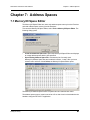
7.1 Memory/IO Space Editor . . . . . . . . . . . . . . . . . . . . . . . . . . . . . . . . . . . . . . 67
7.2 Memory Region for Host Emulation. . . . . . . . . . . . . . . . . . . . . . . . . . . . . . 68
Chapter 8
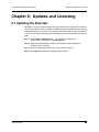
Updates and Licensing . . . . . . . . . . . . . . . . . 69
8.1 Updating the Exerciser . . . . . . . . . . . . . . . . . . . . . . . . . . . . . . . . . . . . . . . 69
8.2 License Keys . . . . . . . . . . . . . . . . . . . . . . . . . . . . . . . . . . . . . . . . . . . . . . . 70
8.3 License Information . . . . . . . . . . . . . . . . . . . . . . . . . . . . . . . . . . . . . . . . . . 70
Appendix A Configuration Space Decoding . . . . . . . . . . 71
A.1 Mandatory Definitions . . . . . . . . . . . . . . . . . . . . . . . . . . . . . . . . . . . . . . . .
A.2 Mandatory Module Functions . . . . . . . . . . . . . . . . . . . . . . . . . . . . . . . . . .
A.3 Configuration Register Types . . . . . . . . . . . . . . . . . . . . . . . . . . . . . . . . . .
A.4 Primitives . . . . . . . . . . . . . . . . . . . . . . . . . . . . . . . . . . . . . . . . . . . . . . . . .
A.5 Helper File. . . . . . . . . . . . . . . . . . . . . . . . . . . . . . . . . . . . . . . . . . . . . . . . .
71
71
72
72
73
Appendix B China Restriction of Hazardous Substances
Table74
How to Contact Teledyne LeCroy . . . . . . . . . . . . . . . . . . 75
Index
77
iv
Teledyne LeCroy
Summit Z2-16 Exerciser User Manual
Section 1
Section 1. General
Teledyne LeCroy
1
Section 1
2
Summit Z2-16 Exerciser User Manual
Teledyne LeCroy
Summit Z2-16 Exerciser User Manual
Chapter 1: Overview
Chapter 1: Overview
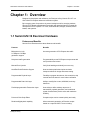
Designed for developers and validators, the Teledyne LeCroy Summit Z2-16™ is a
Gen1/Gen2 PCI Express advanced verification system.
By leveraging years of experience in protocol analysis tools for emerging markets,
Summit Z2-16 blends sophisticated functionality with practical features to speed the
development of PCI Express™ IP cores, semiconductors, bridges, switches, add-in
boards, and systems.
1.1 Summit Z2-16 Exerciser Hardware
Features and Benefits
Summit Z2-16 Exercisers have these features and benefits
Features
Benefits
Bidirectional x1-x16,
2.5 GBps to 5.0 GBps
generation support
Accurate generation of PCI Express bus traffic
Script level traffic generation
Programmability to test PCI Express components with
more precision and control
Manual Error injection
Verify fault handling and identify error recovery
Host/End-Point Emulation Support
Host emulation platform/end-point emulation
Interposer allows for design and stress testing.
Programmable Physical Layer
Flexibility to program lane skews, link control bits, skip
intervals and link states for more robust verification
Programmable Data Link Layer
Ability to modify flow control, ACK/NAK, and retry
behaviors
Flexible/programmable Transaction Layer
User ability to define arbitrary sequence of
transactions, payload generation, and conditional
repeat of transactions provide users with maximum
flexibility
Point and Click Script Editor
Complex scripts can be created quickly and easily
Read/modify/playback capability
Allows automatic generation of Exerciser scripts
based on a captured CATC Trace recording.
Teledyne LeCroy
3
Chapter 1: Overview
Summit Z2-16 Exerciser User Manual
Programmable ACK/NAK behavior
ACK all TLP packets
NAK all TLP packets
Automatic ACK/NAK behavior
ACK/NAK delay timer
Programmable Flow control behavior
Set Credit values
Disable Credit checking
Set Update FC intervals
Automatic CRC
calculation and Sequence number
assignment
DLLP CRC calculation
TLP LCRC calculation
Replay buffer
Programmable Transaction timeout timer
Auto Recovery behavior after 4 Replays
Programmable
configuration space
Full 4 KB configuration space configurable by user
Accessible through Configuration Reads and Writes
over PCI Express
Endpoint memory emulation
Up to 1 GB memory accessible through memory read
and write
Fast Transit module
Special hardware-accelerated module to increase
link utilization
4
Teledyne LeCroy
Summit Z2-16 Exerciser User Manual
Chapter 1: Overview
1.2 Summit Z2-16 Exerciser
Teledyne LeCroy Summit Z2-16, a Gen2 PCI Express 16-lane advanced Exerciser
system, is a critical test and verification tool intended to assist engineers in improving the
reliability of their systems. It can emulate PCI Express root complexes or device
endpoints. You can test PCI Express IP cores, semiconductors, bridges, switches, and
systems.
The Summit Z2-16 is a stand-alone PCI Express Exerciser that can generate and
respond to all types of PCI Express transactions. The scripting language allows creation
of Transaction Layer Packets (TLPs), Data Link Layer Packets (DLLPs) and Ordered
Sets. ACK's and NAK's can be automatically generated under user control.
A Configuration Space can be easily created using the Configuration Space Editor.
The scripting language is powerful yet easy to use. One way to create test scripts is to
export traffic from a CATC Trace file captured with Teledyne LeCroy PETracer. You can
then modify the exported script to generate different test cases, insert errors, or create
loop tests. The “point and click” capability of the script editor simplifies modifying or
creating scripts.
1.3 Other Documents
For more information, refer to the following documents:
Teledyne LeCroy
•
Teledyne LeCroy Analyzers File-based Decoding Manual
•
PETracer/Trainer Automation Manual
•
PETracer VSE Manual
•
PETracer Gen2 Multi Lead Probe User Manual
•
PETrainer Scripting Language Reference Manual
•
PETracer Online Help
5
Chapter 1: Overview
6
Summit Z2-16 Exerciser User Manual
Teledyne LeCroy
Summit Z2-16 Exerciser User Manual
Chapter 2: Hardware Description
Chapter 2: Hardware Description
The PCI Express™ system features Summit Exercisers.
2.1 System Components
•
Summit Z2-16 exerciser system:
•
Summit Z2-16™ exerciser box
•
One or two (for x8 or x16 recording) probe data cables
•
x16 to x1 Edge Adapter
•
x16 to x4 Edge Adapter
•
x16 to x8 Edge Adapter
•
PETracer Software program CD-ROM
•
Device Emulator Card or Host Emulation Test Fixture
2.2 Host Machine Requirements
Summit Z2-16 connects to a host machine. Please consult the readme file on the
installation CD for the latest host machine requirements.
Teledyne LeCroy
7
Chapter 2: Hardware Description
Summit Z2-16 Exerciser User Manual
2.3 Summit Z2-16 Exerciser
A Multi-lane PCI Express Exerciser is designed to assist engineers in improving reliability
of their solutions and providing advanced capabilities for stress and compliance testing.
•
Summit Z2-16: x1 through x16 lane system
All models operate as standalone Exercisers capable of generating and responding to all
types of PCI Express transactions. Exercisers also have the ability to create protocol
variations and anomalies. Users may also create corner case and stress test scenarios
to evaluate the robustness of their solutions. By utilizing the error injection feature,
engineers can create worst-case PCI Express traffic scenarios allowing them to validate
the error handling capabilities of their solutions.
When used in conjunction with an Analyzer, a complete expert test and analysis system
is created. This integrated solution delivers traffic generation and expert protocol analysis
to assist developers with early validation of designs along with error injection and stress
testing in preparation for compliance testing.
8
Teledyne LeCroy
Summit Z2-16 Exerciser User Manual
Chapter 2: Hardware Description
2.4 Summit Z2-16 Front Panel Description
When powered on, the Summit Z2-16 Exerciser activates the user-accessible controls
and LEDs on the front and rear panels.
Warning!
Figure 2.1
Do not open the enclosure. There are no operator serviceable parts inside.
Refer servicing to Teledyne LeCroy.
Summit Z2-16 Front Panel
Power Switch
On/Off switch.
Outputs
To Device (15:8) Connector
Connects Summit Z2-16 to Device Emulator or Host Emulator (lanes 15:8).
Reference Clock In Connector
Connects external reference clock source to Summit Z2-16.
To Device (7:0) Connector
Connects Summit Z2-16 to Device Emulator or Host Emulator (lanes 7:0).
To Analyzer (15:8) Connector
Connects to PETracer Summit or Summit T2-16 Analyzer (lanes 15:8). This is an optional
connection for users adding a PETracer Summit or Summit T2-16 Analyzer to their setup.
Reference Clock Out Connector
Provides external reference clock output.
To Analyzer (7:0) Connector
Connects to PETracer Summit or Summit T2-16 Analyzer (lanes 7:0). This is an optional
connection for users adding a PETracer Summit or Summit T2-16 Analyzer to their setup.
Teledyne LeCroy
9
Chapter 2: Hardware Description
Summit Z2-16 Exerciser User Manual
Displays
Screen
Displays the setup and activity.
Up-Arrow Button
Scroll the screen up.
Select Button
Push to select the current screen item.
Down-Arrow Button
Scroll the screen down.
Link Speed LED
Indicates link speed: blue = 2.5 GT/s or red = 5.0 GT/s.
Link State LED
Indicates state of the link between the Exerciser and the DUT: blue = good or red = error.
Status LED
Indicates status of the Exerciser: blue = good or red = error.
Manual Action Button
(Not used at this time)
10
Teledyne LeCroy
Summit Z2-16 Exerciser User Manual
Chapter 2: Hardware Description
2.5 Summit Z2-16 Rear Panel Description
From left to right, the Summit Z2-16 rear panel contains the following components:
Figure 2.2 Summit Z2-16 Rear Panel
Wide-range AC Connector Module
•
Power on/off switch
•
Enclosed 5x20 mm 2.0A 250 V fast acting glass fuse
•
Power socket
Warning!
For continued protection against fire, replace fuse only with the type and
rating specified above.
Sync In and Sync Out Connectors
(not currently active) These connectors allow multiple Summit T2-16 or Summit Z2-16
analyzers to send synchronization and control messages to one another.
USB Type B Host Machine Connector
This connector links an Analyzer to the host machine for the purpose of transmitting
commands from the host machine to the Analyzer and uploading traces from the
Analyzer’s recording memory to the PETracer software for viewing and analysis.
This connector links an Exerciser to the host machine for the purpose of downloading
scripts and controlling the behavior of the Exerciser. Note: For each Analyzer or
Exerciser, use either USB or Ethernet, not both.
Ethernet Port
GIGE Connectivity allows connection to an Ethernet network and sharing of
Analyzer/Exerciser resources by multiple engineers. Note: For each Analyzer or
Exerciser, use either USB or Ethernet, not both.
BNC Connectors Trigger In and Trigger Out
These BNC connectors allow the Analyzer to transmit or receive trigger event signals.
Trigger In can receive a signal from another device and use that signal to trigger the
recording. Conversely, the Trigger Out connector can send an output signal from the
Analyzer to another device.
Teledyne LeCroy
11
Chapter 2: Hardware Description
Summit Z2-16 Exerciser User Manual
RS-232 25-pin Data Input/Output Connector
This connector is not used by Summit Z2-16.
Teledyne LeCroy Bus Connector
The Teledyne LeCroy Bus Connector is not currently active.
12
Teledyne LeCroy
Summit Z2-16 Exerciser User Manual
Chapter 3: Installation
Chapter 3: Installation
Summit Z2-16™ is a stand-alone system.
You can begin traffic generation after following the steps in this chapter.
3.1 Installing the PETracer Software
PETracer software operates all of Teledyne LeCroy’s PCI Express protocol Analyzer and
Exerciser products:
The PETracer software is installed on a Microsoft® Windows®-based host machine and
serves as the interface for the Exerciser and/or Analyzer. An Exerciser enables traffic
generation features.
To install the PETracer software on the host machine:
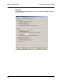
Step 1 Insert the CD into the CD ROM drive of the PC that controls the
Exerciser. The installation window opens and displays links to the
PETracer software, user manuals, a readme file, and Acrobat Reader.
Step 2 Select Install Software and follow the on-screen instructions.
The PETracer software installs automatically on the host machine’s hard disk.
During installation, all necessary USB drivers are loaded automatically. Drivers
included in the installation are:
•
summit.sys: Summit T2-16/Summit Z2-16 driver
Step 3 To start the application, launch the PETracer program from the Start
menu:
Start > Programs > LeCroy > PETracer > LeCroy PETracer
Teledyne LeCroy
13
Chapter 3: Installation
Summit Z2-16 Exerciser User Manual
The PETracer program opens:
Note:
14
The software may be used with or without the Exerciser or Analyzer. When
used without an Exerciser or Analyzer attached to the computer, the program
functions as a CATC Trace Viewer to view, analyze, and print captured
traffic.
Teledyne LeCroy
Summit Z2-16 Exerciser User Manual
Chapter 3: Installation
3.2 Setting Up the Summit Z2-16 Exerciser using an
Ethernet Connection
Step 1 Remove the Exerciser from its shipping container.
Step 2 Connect the Exerciser to a 100-volt to 240-volt, 50 Hz to 60 Hz,
120 W power outlet using the provided power cord.
Note: The Exerciser is capable of supporting supply voltages between 100 volts
and 240 volts, 50 Hz or 60 Hz, thus supporting all known supply voltages around
the world.
Step 3 Connect the Ethernet cable between the Ethernet port on the back of the
Exerciser and a Ethernet port (hub, switch or wall) in your local network.
Continue with Step 4 below.
Note on USB: To connect using USB, see “Setting Up the Summit Z2-16
Exerciser using a USB Connection” on page 18.
Step 4 Turn on the rear power switch and the front power switch.
Note: At power-on, the Exerciser initializes itself in approximately five seconds
and performs an exhaustive self-diagnostic that lasts about forty seconds. The
results are reflected by messages on the Summit Z2-16 LCD display (see
“Summit Z2-16 Front Panel Description” on page 9). If the LCD display indicates
failure, call Teledyne LeCroy Customer Support for assistance.
Connecting to a Summit Z2-16 Exerciser in the
Local Network
After you have installed the PETracer application software, perform the following
procedure to connect to a Summit Z2-16 Exerciser in the local network.
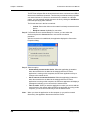
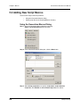
Step 1 Select the Setup > All connected devices… menu in the PETracer
application to display the Analyzer Devices dialog.
Teledyne LeCroy
15
Chapter 3: Installation
Summit Z2-16 Exerciser User Manual
The PETracer software fills the list with devices that are connected over USB or
discovered on the Ethernet network. The discovery mechanism works only within
one network subnet. If a Summit is connected to the network on a different
subnet, you can manually add the subnet to the list by clicking the Add Device
button and specifying the IP address.
The Summit devices in the list are marked:
•
Locked: Some other client on the network is already connected to that
device
•
Ready to connect: Available for connection
Step 2 If a Summit device is marked Ready To Connect, you can select that
device and press the Connect button to execute the connection
procedure.
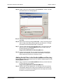
After the connection is established, the application displays the Connection
Properties dialog:
Step 3 Select an option:
Note:
16
•
Automatically connect to the device: When the application is started or
when the named device is added to the network while the PETracer
application is running on this computer, the PETracer application will try to
connect to the named device.
•
Ask if I want to connect to the device: When the application is started or
when the named device is added to the network while the PETracer
application is running on this computer, the PETracer application will display a
message box allowing you to connect to the named device.
•
Take no action: When you start the application or when you want to add the
named device to the network while the PETracer application is running on this
computer, you must connect manually to use the named device.
When you close the application on this computer (or you perform manual
disconnect), the application disconnects from the device.
Teledyne LeCroy
Summit Z2-16 Exerciser User Manual
Chapter 3: Installation
Step 4 Press OK in the Connection Properties dialog.
After you finish the connect procedure, the Summit device to which you have
connected is marked as Ready and you can use it for recording:
Note:
To disconnect from a device, display this dialog, select the device, and click
the Disconnect button.
Warning! Do not change from USB to Ethernet, or back, without power cycling
the Analyzer/Exerciser.
Teledyne LeCroy
17
Chapter 3: Installation
Summit Z2-16 Exerciser User Manual
3.3 Setting Up the Summit Z2-16 Exerciser using a
USB Connection
To set up the Exerciser using a USB connection:
Step 1 Remove the Exerciser from its shipping container.
Step 2 Insert the Installation CD.
Step 3 Connect the Exerciser to a 100-volt to 240-volt, 50 Hz to 60 Hz,
120 W power outlet using the provided power cord.
Note: The Exerciser is capable of supporting supply voltages between 100 volts
and 240 volts, 50 Hz or 60 Hz, thus supporting all known supply voltages around
the world.
Step 4 Connect the USB port to a USB port on the host machine using a USB
cable. Go to Step 4 below.
Note on Ethernet: To connect using Ethernet, see “Setting Up the Summit Z2-16
Exerciser using an Ethernet Connection” on page 15.
Step 5 Turn on the rear power switch and the front power switch.
Note: At power-on, the Exerciser initializes itself in approximately five seconds
and performs an exhaustive self-diagnostic that lasts about forty seconds. The
results are reflected by messages on the Summit Z2-16 LCD display (see
“Summit Z2-16 Front Panel Description” on page 9). If the LCD display indicates
failure, call Teledyne LeCroy Customer Support for assistance.
Step 6 Click Next after you see the Add New Hardware Wizard window.
Step 7 Follow the Microsoft® Windows® on-screen Plug-and-Play instructions
for the automatic installation of the Exerciser as a USB device on your
analyzing host machine. (The required USB files are included on the
Installation CD.)
Step 8 Click Finish when you see the message that says “Windows has
finished installing the software that your new hardware requires” and the
file has been installed in your host machine.
Warning! Do not change from USB to Ethernet, or back, without power cycling
the Analyzer/Exerciser.
18
Teledyne LeCroy
Summit Z2-16 Exerciser User Manual
Chapter 3: Installation
3.4 Connecting Summit Z2-16 to the DUT
The Summit Z2-16 Exerciser can test both the host and device sides of a PCI Express
link through the use of two types of adapter:
•
Motherboards and host controllers: Using a device emulator. A device
emulator is an adapter card that fits into motherboards and other slotted
PCI Express devices.
•
PCI Express add-on cards: Using a host emulation test fixture. A host
emulation test fixture is a box-like adapter with a slot for testing PCI Express
cards.
Both of these test devices can be purchased from Teledyne LeCroy.
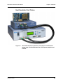
Device Emulator
Figure 3.3
Summit Z2-16 Exerciser (bottom) connected to a
Device Emulator (top).
The Teledyne LeCroy Device Emulator is an adapter that provides a way of connecting a
Summit Z2-16 Exerciser to a PCI Express motherboard. The emulator has two
connectors: a connector for a data cable and an edge connector for inserting the
Device Emulator into a slotted DUT.
Teledyne LeCroy
19
Chapter 3: Installation
Summit Z2-16 Exerciser User Manual
Installing the Device Emulator
To install the Device Emulator into the DUT, perform the following steps:
Step 1 If not already powered off, power off the Summit Z2-16 system and the
DUT.
Step 2 Insert the edge connector on the Device Emulator into a PCI Express
slot in the DUT. The Device Emulator is designed to fit into standard x16
PCI Express slot. To connect to a x1, x4, or x8 slot, you must install a slot
reducer, available from Teledyne LeCroy.
Step 3 The Device Emulator is shipped from Teledyne LeCroy with a metal face
plate for attachment to a PC case. If you are working with a motherboard
that is not in a PC case, you may prefer to remove the metal face plate
so the emulator can sit flat with the motherboard. To remove the face
plate, unscrew the two screws that hold it onto the emulator.
Step 4 Attach probe data cables between the two connectors on the emulator
and the To Device (15:8) and To Device (7:0) ports on the Exerciser.
Step 5 At this point the emulator is ready for use. Skip ahead to See “Final
Steps: Power on the Exerciser and then DUT” on page 22..
20
Teledyne LeCroy
Summit Z2-16 Exerciser User Manual
Chapter 3: Installation
Host Emulation Test Fixture
Figure 3.4
Teledyne LeCroy
Summit Z2-16 Exerciser (bottom) connected to a Host Emulator
adapter (top). The Host Emulator has a PCI Express graphics card
inserted.
21
Chapter 3: Installation
Summit Z2-16 Exerciser User Manual
Teledyne LeCroy Host Emulation Test Fixture
Hardware enclosure with a slot on top for accommodating a PCI Express card.
TX/RX 8-15 Connector: Connects to the To Device (15:8) port on Summit Z2-16.
TX/RX 0-7 Connector: Connects to the To Device (7:0) port on Summit Z2-16.
Reset button: Reset asserts PERST # for > 250 ms.
Clock Select: Selects from the following clocking options:
•
Ext: a user supplied reference via the RefCLK SMA connector.
•
Int: an internal supplied 100 MHz reference clock.
•
Int SSC: an internal supplied Spread Spectrum Clock.
Power Select switch: Selects between the internal power supply and the external power
jacks on the back of the emulator. When External power is selected, both 3.3V and 12V
supplies must be provided by the user via the banana jacks on the back of the emulator.
Emulator Power LED: Lights when emulator is powered on.
PCIE Slot Power LED: Lights when the PCI Express connector on the Host Emulator is
supplying power. Power can be provided either via the internal power supply or by an
external power supply via the banana jacks on the back of the emulator. If an external
power source is provided, the Power Select switch should be set to Ext.
Installing the Host Emulation Test Fixture
Step 1 If not already powered off, power off the Summit Z2-16 system and the
DUT.
Step 2 Insert the male edge connector of the DUT into the PCI Express slot on
top of the Host Emulation Test Fixture.
Step 3 Attach a probe data cable to the Rx/Tx 0-7 port on the Host Emulator and
the To Device (7:0) port on Summit Z2-16.
Step 4 For x16 configuration, attach a second probe data cable to the
Rx/Tx 8-15 port on the Host Emulator and the To Device (15:8) port on
Summit Z2-16.
Step 5 If the DUT is a 150 watts or less device, such as a graphics card, you
may connect the card’s external power cables to the two external power
ports on top of the Host Emulator.
Final Steps: Power on the Exerciser and then DUT
Important: Power on the Exerciser before you power on the DUT.
Step 1 Power on the Summit Z2-16 Exerciser. The Exerciser's green power
LED lights, and the red Status LED turns on for approximately one
minute while the Exerciser performs self-diagnostics.
Step 2 If testing a motherboard, power on the motherboard. If testing a
PCI-Express device such as a graphics card, power on the
Host Emulator.
Step 3 Open the PETracer application on the host machine. The Exerciser is
now ready for traffic generation.
22
Teledyne LeCroy
Summit Z2-16 Exerciser User Manual
Chapter 3: Installation
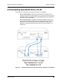
3.5 Connecting Summit Z2-16 to a T2-16
The Summit Z2-16 Exerciser connected to a Summit T2-16 Analyzer.
•
For an x8 connection: Connect one end of the iPass Y-Cable to the To
Analyzer [7:0] connector of the Summit Z2-16. Connect the other two ends of
the iPass Y-Cable to the Upstream [7:0] and Downstream [7:0] connectors of
the Summit T2-16 respectively.
•
For an x16 connection: In addition to the above connection, connect one
end of the second iPass Y-Cable to the To Analyzer [15:8] connector of the
Summit Z2-16. Connect the other two ends of the iPass Y-Cable to the
Upstream [15:8] and Downstream [15:8] connectors of the Summit T2-16
respectively.
Figure 3.5
Teledyne LeCroy
Summit Z2-16 Exerciser (top) connected to a Summit T2-16 (bottom).
23
Chapter 3: Installation
24
Summit Z2-16 Exerciser User Manual
Teledyne LeCroy
Summit Z2-16 Exerciser User Manual
Section 3
Section 2. Exerciser Traffic Generation
Teledyne LeCroy
25
Section 3
26
Summit Z2-16 Exerciser User Manual
Teledyne LeCroy
Summit Z2-16 Exerciser User Manual
Chapter 4: Traffic Generation
Chapter 4: Traffic Generation
A traffic generator can emulate PCI Express™ root complexes and endpoint devices.
Traffic generation can be used to transmit known errors, allowing you to observe how
your device handles faulty link conditions.
After the Summit Z2-16 Exerciser and DUT have been cabled and powered on, you can
test the setup by generating some traffic. The following steps show how to configure the
Exerciser to generate a Link Training sequence.
4.1 Theory of Operation
Overview
The Exerciser offers two mechanisms for implementing traffic generation: scripts, in
which any type of traffic can be defined and executed, and the Generation Options dialog
box, which offers a collection of PCI Express specific behaviors that can be enabled for
automatic generation of traffic.
Using scripts, packets can be transmitted one after another or with certain timing or
event-based pauses between them. This allows the Exerciser to act as a pattern generator
with PCI Express-specific formatting and transmission rates. However, creating traffic
that emulates real devices with relatively complex protocol behaviors using a simple
pattern generator is quite complicated. Certain behaviors such as ACK policies, and flow
control require concurrent processing. This is where the automated features become
useful.
The Exerciser includes a collection of automated traffic generation circuits that commonly
exist in other PCI Express devices. These circuits include ACK/NAK generation, flow
control management, a Link Training and Status State machine (LTSSM), replay buffers,
and transaction timers. What makes the Exerciser unique and so useful is that each of
these behaviors can be individually modified or disabled. This allows the user to perform
operations that might not otherwise be possible using an off the shelf PCI Express
device. This can be particularly useful when doing compliance or fault recovery testing.
Starting Point
When the Exerciser first powers up, it is at electrical idle on all lanes. The link is not
trained, but the Link Training and Status State Machine (LTSSM) is enabled and waiting
for a command to train the link. To begin communication with a PCI Express device, the
Link training must occur, but first the generation settings must be set. This involves
setting the Link parameters such as link width, polarity inversion, and lane reversal,
through the Generation Options dialog.
Note:
Setting the options in the Generation Options dialog has no effect on the
Exerciser behavior until the first script is executed. In fact, each time a script
is executed, these behaviors are reprogrammed to the Exerciser and the
behaviors are modified accordingly.
The Link Connect toolbar button can then be pressed to signal to the LTSSM to initiate
Link training. Alternatively, a script can executed with the Link=L0 command.
Teledyne LeCroy
27
Chapter 4: Traffic Generation
Summit Z2-16 Exerciser User Manual
The Status bar at the bottom of the screen shows the current state of the PCI Express
Link. When the Link is down, it shows Detect. When it is up, it shows L0.
All of the intermediate link states, such as Polling and Configuration, are handled
automatically. In fact, after the Link=L0 command is executed and the LTSSM is alive,
the Exerciser attempts to keep the Link active just as any other PCI Express device does.
This includes handling of Recovery states and subsequent retraining events.
The next step is to enable flow control. This is done by executing the Link=InitFC
command. This causes the Exerciser to perform flow control initialization and, if enabled,
begin periodic transmission of Update_FC DLLP's. If the Link connect toolbar button was
used, the flow control initialization happens automatically.
By using these basic commands, the complicated process of link training is managed
automatically. The Link is now trained and the script execution can now focus on sending
TLP packets.
Script Execution
As mentioned above, each time a script is executed, the configuration settings for the
Exerciser are reprogrammed. When the Start generation button is pressed, the script is
uploaded to the Exerciser hardware and executed immediately. Progress of the script can
be tracked in the status bar at the bottom of the screen. Subsequent executions of the
same script do not require upload of the script to the Exerciser, however, as mentioned
above, the generation options are still reprogrammed.
Script execution can be throttled using Wait commands inserted directly into the script.
Waits can be time based, require receipt of certain packet types, or can even require
User input from the GUI.
After the script is complete, any enabled PCI Express behaviors, such as SKIP insertion,
Flow control, and ACK generation, continue. This allows you to run multiple scripts, one
after another, without interrupting the Link state.
28
Teledyne LeCroy
Summit Z2-16 Exerciser User Manual
Chapter 4: Traffic Generation
4.1 Traffic Generation Files
The .peg traffic generation files are text files consisting of a series of commands from a
scripting language (see Chapter 12), and optionally, one or more Include statements
linking other generation files into the current file.
Note:
To edit a generation file, use the Script Editor, a specially designed text editor
tool. See “Editing Generation Files with the Script Editor” on page 34.
To generate traffic, open a traffic generation file (*.peg) and then run it.
Teledyne LeCroy
29
Chapter 4: Traffic Generation
Summit Z2-16 Exerciser User Manual
When the file is opened, it appears in the CATC Trace window looking like a CATC Trace
file.
To run the file, press
.
To create or edit a .peg file, use the Script Editor.
The Script Editor is a text-editing tool that can be opened by clicking
.
Alternatively, the traffic generation file can be created by exporting the data from a
CATC Trace into a traffic generator file.
30
Teledyne LeCroy
Summit Z2-16 Exerciser User Manual
Chapter 4: Traffic Generation
4.2 Creating a Traffic Generation File
There are four ways to create traffic generation script file:
•
Export an existing trace to a script file
•
Save an existing script to a new file
•
Select File > New to create a new and empty script file that contains no text.
•
Create an empty file using an OS shell (with .peg extension) and open it with
PETracer software.
Exporting a CATC Trace to a Traffic Generation File
A simple way to create a script file is to open a CATC Trace and then to export the
CATC Trace data to a generation file:
Step 1 Open a CATC Trace file.
Step 2 Select File > Export > to Generator File Format.
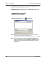
Step 3 Select the desired options from the File Export dialog box:
Direction: Selects the direction of the traffic to be exported.
From and To: Selects a range for exporting. You can export all or part of the CATC Trace.
Do not export hidden packets: Ignores any packets hidden through the various hide
options.
Do not export Idle packets: Excludes Idles from the export.
Teledyne LeCroy
31
Chapter 4: Traffic Generation
Summit Z2-16 Exerciser User Manual
Export “Wait for Cpl” from upstream: Exports all Wait for Completions from the
opposite direction. Wait = TLP is a script command.
Export “Wait for ACK” from upstream: Exports all Wait for ACK DLLPs from the
opposite direction.
Saving a Script to a New File
To save a script file as a generation file:
Step 1 Open an existing script file.
Step 2 Select File > Save As… or click
on the toolbar.
Step 3 Navigate to the desired folder and type a new file name where you want
to save the current script, then click the Save button:
When the Save As command completes, the newly created script is displayed.
Note:
32
The Save As dialog box includes the option Save all included files. This
option causes the software to save any Include files that have included into
the script. The Included files are saved to the same directory as the traffic
generation file.
Teledyne LeCroy
Summit Z2-16 Exerciser User Manual
Chapter 4: Traffic Generation
Creating a New Empty Generation File
To create a generation file from scratch:
Step 1 Select File > New Script or use the shortcut Ctrl+N.
An empty traffic generation file appears. You can also view the Script Editor.
Teledyne LeCroy
33
Chapter 4: Traffic Generation
Summit Z2-16 Exerciser User Manual
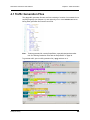
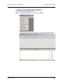
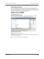
4.3 Editing Generation Files with the Script Editor
The Script Editor is an editing tool for traffic generation files (<filename>.peg). The
generation script is presented in the Script Edit window. Parameters are presented in
menus and text boxes in the Command Properties window in the right-hand portion of the
Script Editor.
To launch the Script Editor: click the Script Editor button
on the toolbar or
right-click the CATC Trace window and choose Edit as Text from the pop-up menu.
The Script Editor window displays in the lower portion of the CATC Trace window.
Layout: The Script Editor divides into four areas:
•
Script Editor toolbar: Presents options for printing, saving, bookmarking,
and other options.
•
Script Edit window: Main window where the script is displayed and edited.
Text in this window behaves as in most text editors. Text can be copied,
pasted, and searched.
•
Command Properties window: Presents editable parameters. Many
parameters have menus. Click the parameter in the Command Properties
window to see if a down-arrow appears.
•
File tabs: Lists the name of the traffic generation file and any open Include
files that are associated with the generation file. If the generation file has
Include statements, the Include files automatically open and display as tabs
in the File tabs section of the Editor window.
Error Log: An error log opens automatically at the bottom of the window any time a script
error occurs. The window closes automatically whenever the error is corrected, after you
save the script.
34
Teledyne LeCroy
Summit Z2-16 Exerciser User Manual
Chapter 4: Traffic Generation
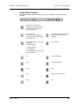
Script Editor Toolbar
The toolbar contains buttons for saving your edits, navigating, searching and other
functions.
Save. Saves your edits and
immediately updates the setting
bars and Frames shown in the
CATC Trace window.
Go to Trace View.
Causes trace view to bring the
currently selected script line to the
top of the screen.
Toggle Bookmark. Allows markers
to be set or removed to aid in
navigation.
View Options. Opens a menu with
three options:
• Enable Outlining
Next Bookmark.
• Toggle Outlining
• Line Numbers.
See “View Options Menu” on page
40 for descriptions.
Teledyne LeCroy
Cut.
Previous Bookmark.
Copy.
Clear All Bookmarks.
Paste.
Find.
Undo.
Replace. Find and replace.
Redo.
Print.
35
Chapter 4: Traffic Generation
Summit Z2-16 Exerciser User Manual
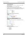
Script Edit Window
The Script Edit Window offers several features to simplify the process of editing.
Syntax Highlighting
All known commands and parameters are highlighted in blue.
All predefined values and command modifiers are highlighted in brown.
Intellisense prompts for known predefined values/literals. This functionality is invoked
when you type = after a known key or select List values from the Context menu.
Tooltips
The Tooltips look like the following:
Outlining
When outlining is enabled user have the option to collapse/expand code blocks:
Text Editing Commands
The Script Editor supports standard editor commands:
36
•
Copy/Paste
•
Undo/Redo
•
Find/Replace
•
Bookmarks
Teledyne LeCroy
Summit Z2-16 Exerciser User Manual
Chapter 4: Traffic Generation
Synchronized Scrolling with the CATC Trace Window
You can navigate from the generation code window to the corresponding place in the
CATC Trace representation, and visa versa.
From the CATC Trace window, right-click the first cell in a packet in the CATC Trace
window and select Go to Script Editor from the pop-up menu. The Script Editor window
then repositions to the corresponding code.
From the script editor, right-click some code within the Script Editor window and select
Position Trace view on packet x from the pop-up menu (where x is a packet number).
The CATC Trace window repositions to the corresponding packet number.
Teledyne LeCroy
37
Chapter 4: Traffic Generation
Summit Z2-16 Exerciser User Manual
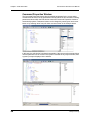
Command Properties Window
The Command Properties window lists all possible parameters for the current script
command and all values for the parameters currently defined in this command. Entering
parameters/values within the Edit window causes the Command Properties window to
automatically update. Parameters/values can be changed by entering text into the text
boxes or by selecting items from pull-down menus as shown in the example below.
In this case, the edit window is updated automatically. If the current script command does
not have parameters or the current cursor position is outside of any script command, then
a generic prompt is displayed in the window:
38
Teledyne LeCroy
Summit Z2-16 Exerciser User Manual
Chapter 4: Traffic Generation
Script Editor File Tabs
At the bottom of the Script Editor window is the name of the open generation file.
If there are Include statements in the generation file that link it to other generation files,
these files automatically open and display as tabs at the bottom of the window. You can
click the tabs to toggle between the open generation files.
Script Editor Error Log
Whenever you create a scripting error, a log opens at the bottom of the application
window. When the error is corrected, the window automatically closes.
Errors: Marked by red squares.
Warnings: Marked by yellow squares.
Double-clicking an error in the error log causes the cursor in the edit window to move to
where the error was detected.
Note:
Teledyne LeCroy
You cannot run the script if it has syntax errors.
39
Chapter 4: Traffic Generation
Summit Z2-16 Exerciser User Manual
View Options Menu
The View Options button displays a menu with these options:
Enable Outlining: Adds an expandable/collapsible tree structure to the left side of the
Script Editor showing the hierarchical relationships of the script lines.
Show Line Numbers: Adds line numbers to the left side of the Script Editor window.
Show Tooltips: Allows tooltip pop-ups, which provide descriptions of script keywords
when cursor mouses over a keyword.
Toggle Outlining: Toggles the outline tree between collapsed and expanded states.
4.4 Generation Options Dialogs Overview
The Generation Options dialog box is used to set Config settings in a traffic generation
script (for example, Config = General or Config = Link). This dialog duplicates the
Config script command and is provided as a convenient alternative means of setting this
command in the script.
Note:
The Generation Options dialog is subordinate to the script itself, so script
commands override options selected in this dialog box.
Opening the Dialog
To open the Generation Options dialog, select Setup > Generation Options or click
the Generation Options button
.
Dialog Layout
The Generation Options dialog is organized into five pages: General, Link, Integrity, Flow
Control, and Transactions.
40
Teledyne LeCroy
Summit Z2-16 Exerciser User Manual
Chapter 4: Traffic Generation
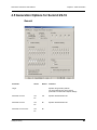
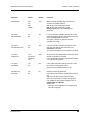
4.5 Generation Options for Summit Z2-16
General
Parameter
Values
Default
Target
Comment
Specifies the generation platform.
The choice affects some of the options
presented in the Generation Options dialogs.
Data Rate 2.5 GT/s
Yes
No
Yes
Specifies advertised data rate.
Data Rate 5.0 GT/s
Yes
No
No
Specifies advertised data rate.
Data Rate 5.0 & 2.5 GT/s
Yes
No
No
Teledyne LeCroy
41
Chapter 4: Traffic Generation
Summit Z2-16 Exerciser User Manual
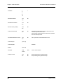
LinkWidth
1
2
4
8
16
1
DisableScrambleTx
Yes
No
No
DisableDescrambleRx
Yes
No
No
Reverse Lanes (TX/RX)
Yes
No
No
Follow Lane Reversal
Yes
No
No
When set, the Summit Z2-16 Trainer responds to lane
reversal requests from the DUT.
When cleared, the Summit Z2-16 Trainer does not follow
the lane reversal protocol.
Use External Reference Clock
Yes
No
No
Use if you have an external reference clock.
InvertPolarityTx
(X,X,X,X)
InvertPolarityRx
Disabled
SkewTx
(X,X,X,X)
Interposer
Host
Device
Host
Host = Host Emulation
Analyzer Control
Yes
No
No
No
Start recording when generation starts.
Stop recording when generation stops.
42
Teledyne LeCroy
Summit Z2-16 Exerciser User Manual
Chapter 4: Traffic Generation
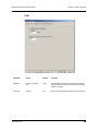
Link
Parameter
Values
Default
Comment
SkipTimer
number of symbols
Off
1360
Periodic timer that controls sending of SKIP ordered
sets at specific intervals. Timer’s value is measured in
number of symbols.
FTSCount
0 to 255
255
Number of FTS ordered sets required (as sent in TS)
Teledyne LeCroy
43
Chapter 4: Traffic Generation
Summit Z2-16 Exerciser User Manual
Integrity
The Integrity page sets the parameters for two Config commands: Config = TLP and
Config = AckNak
44
Teledyne LeCroy
Summit Z2-16 Exerciser User Manual
Chapter 4: Traffic Generation
Parameter
Values
Default
Comment
AckNak Policy
Auto
Ack
Nak
Disable
Auto
Auto: Automatic ACK/NAK DLLP generation for
received TLP packets (default).
Ack: Always ACK received TLP packets
Nak: Always NAK received TLP packets
Disable: Disable automatic ACK/NAK DLLP
generation.
TLP Policy
AutoSeqNumber
Yes
No
Yes
If not set, overrides automatic generation of the TLP
sequence number and uses user-defined value of the
field in the Packet=TLP commands.
This option overrides any sequence numbers
specified in the script.
TLP Policy
AutoGenerate LCRC
Yes
No
Yes
If not set, overrides automatic generation of LCRC
and uses user-defined value of the field in the
Packet=TLP commands.
This option overrides any LCRC specified in the script.
TLP Policy
ReplayTimer
In ns
(rounded to
nearest 8)
Off
4200
Timeout in TLP transmitter path that counts time since
last Ack or Nak DLLP is received.
If set, automatically retransmit TLPs that were NAKed
or on replay timer expiration.
TLP Policy
AutoRetrain
Yes
No
Yes
If set, enable automatic retraining of the link in case
the number of retransmitted TLP is 4.
Valid only when AutoRetransmission is set.
Automatic Tag
Generation
Yes
No
No
Disable automatic tag generation.
Prevents the Exerciser from automatically inserting a
tag.
Tags are a sub-field of the transaction ID field.
When auto tag insertion is enabled, the tag field is
only modified for non-posted transactions such as
CfgRd, CfgWr, and MemRd.
Options are:
Use lower 5-bit of Tag field. Zero out higher 3 bits.
Use 8-bit of Tag field.
Teledyne LeCroy
45
Chapter 4: Traffic Generation
Summit Z2-16 Exerciser User Manual
Flow Control
The Flow Control page sets parameters for Config = FCTx and Config = FCRx.
46
Teledyne LeCroy
Summit Z2-16 Exerciser User Manual
Chapter 4: Traffic Generation
FCRx Parameter
Values
Default
Comment
Enable Tx Flow Control
Yes
No
Yes
When not set, the TLPs are being sent without
the regard of how many credits are available.
This option prevents TLP transmission if
insufficient credits are available.
Enable Rx Flow Control
In ns
(rounded to nearest 8)
Off
4200
When enabled, allows automatic updating of
these DLLPs.
This option enables a periodic timer that
controls sending of UpdateFC DLLPs. You
should leave timer and credit values to
defaults for correct behavior.
PH
0 to 255
1
Posted Request Headers
NPH
0 to 255
1
Non-Posted Request Headers
CplH
0 to 255
1
Completion Headers
PD
0 to 4095
1024
Posted Request Data Payload
NPD
0 to 4095
1
Non-Posted Request Data Payload
CplD
0 to 4095
1024
Completion Data Payload
Teledyne LeCroy
47
Chapter 4: Traffic Generation
Summit Z2-16 Exerciser User Manual
Transactions
Default
Parameter
Values
Default
Comment
Automatically
handle
Configuration
Read and Write
TLP transactions
Yes
No
No
If set, automatically handles Configuration Read and
Write TLP transactions.
For Configuration Read transactions, Completion TLP
contains the data read from the internal Configuration
Space according to the specified register address.
For Configuration Write transactions, the internal
Configuration Space is updated at the address with the
data from Configuration Write TLP, and Configuration
Write Completion is returned.
This option enables Read and Write access to 4-KB
configuration space.
48
Teledyne LeCroy
Summit Z2-16 Exerciser User Manual
Chapter 4: Traffic Generation
Automatically
handle Memory
and IO Read
and Write TLP
transactions
Yes
No
No
If set, automatically handles Memory and IO Read and
Write TLP transactions.
For Memory and IO Read transactions, Completion TLP
contains the data read from the internal Memory/IO
Address Space according to the specified address.
For Memory and IO Write transactions, internal
Memory/IO Address Space is updated at the address
with the data from TLP.
Enable Fast
Memory
Completer
Yes
No
No
If set, enables the high-performance memory completer
functionality.
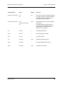
Region
--Not Set-Mem_64
Mem_32A
Mem_32B
Fixed_64
Fixed_32
--Not Set--
A Region is a range of addresses in PCI Express
memory space, which the high-performance memory
completer handles using a defined policy.
There are two region types:
• The first type is defined by the fixed address location,
such as Fixed_32 and Fixed_64, and can be used for
both Device and Host Emulation.
• The second type is defined by the specific device
memory space, such as Mem_64, Mem_32A, and
Mem_32B, specified in the BAR setup (see “BARs
Setup” on page 65) in the Configuration Space Editor,
and can be used only for Device Emulation.
The supplied Address is really the Offset from the
beginning of the corresponding memory space. The
actual address is calculated by the Summit Z2-16
Trainer when the BARs are configured.
When a region is enabled, all Write data to the address
range is consumed at high speed and discarded. All
completion data for read requests is filled according to
the rules specified by the PldGrowth and PldSeed
parameters.
Six regions are currently available for the fast memory
completer.
FastMemoryCompleter must be set to enable the
Region.
Address/Offset
(hex)
Teledyne LeCroy
32-bit
Address/Offset
64-bit
Address/Offset
32-bit
0x00000000
If the corresponding Region is set, based on the region
type, this field is a
32-bit Offset for Mem_32A and Mem_32B, 64-bit Offset
for Mem_64,
32-bit Address for Fixed_32, and
64-bit Address for Fixed_64.
The corresponding Region must be set to enable the
Address/Offset.
49
Chapter 4: Traffic Generation
Summit Z2-16 Exerciser User Manual
Length
(in 4-KB blocks)
0 to 1,048,576
0
If the corresponding Region is set, this field specifies the
length of the address range in 4-kilobyte blocks, starting
from the address/offset, in the Address/Offset field, to
which the fast memory completer responds.
The corresponding Region must be set to enable
Length.
PldGrowth
Fixed Byte
Fixed DWord
Incr Byte
Incr DWord
Fixed Byte
If the corresponding Region is set, this field specifies the
expected payload format.
Fixed Byte and Fixed DWord specify a payload of a byte
or dword pattern consisting of PldSeed.
Incr Byte and Incr DWord specify a payload of
incrementing bytes or dwords starting from zero.
The corresponding Region must be set to enable
PldGrowth.
PldSeed (hex)
8-bit value
10-bit value
0
If the corresponding Region is set and PldGrowth is set
to Fixed Byte or Fixed DWord, this field species the byte
value repeated for PldGrowth of Fixed Byte or the 10-bit
dword value for PldGrowth of Fixed DWord.
For other types of PldGrowth, this field is set to zero.
The corresponding Region and PldGrowth must be set
to enable Pldseed.
Example .gen File
50
Teledyne LeCroy
Summit Z2-16 Exerciser User Manual
Chapter 4: Traffic Generation
4.6 Generating Traffic: Set Generation Options
Before beginning generation, set options in the Generation Options dialog box:
Step 1 Open the Generation Options dialog box by selecting
Setup > Generation Options from the menu. The Generation Options
dialog opens.
By default the General page displays.
Step 2 To test 1.0 devices, check the box next to
Base Spec Rev. 1.0 Compatibility Mode to select 1.0 compatibility
mode.
To test 1.0A devices, leave this box unchecked.
Step 3 Set the generation direction based on type of device you are emulating.
Step 4 Select one of the two Interposer options:
•
Host Emulation: Select Host
•
Device Emulation: Select Device
Step 5 Select the Link tab. The Link page opens.
Step 6 Select Enable Automatic Skip Generation, but leave the setting at the
default value: 4720 ns.
Step 7 Select the Integrity tab. The Integrity page opens.
Step 8 Check to enable Automatic ACK/NAK DLLP generation for received
TLP packets.
Step 9 Enable all four TLP policies.
Step 10 Select the Flow Control tab. The Flow Control page opens.
Step 11 Check the checkbox to enable Do not send TLP packet if credit
amount is insufficient.
Step 12 Check the checkbox to enable
Periodically schedule UpdateFC DLLP.
Step 13 Use the defaults for all other boxes.
Step 14 Click OK to apply all changes and close the Generation Options dialog.
Teledyne LeCroy
51
Chapter 4: Traffic Generation
Summit Z2-16 Exerciser User Manual
4.7 Generating Traffic: Prepare Traffic Generation
To prepare for traffic generation, follow these steps:
Step 1 If it is not running, start the PETracer™ software.
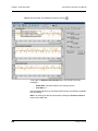
Step 2 Open an existing script file or create a new script. For example, open the
traffic generation file Linkup.peg by selecting File > Open from the
menu. The following packets display in the main window.
The CATC Trace window shows the type of traffic that is to be generated in the
current generation session.
Step 3 If needed, make changes to the script file,
then save the file by clicking the Save button
52
.
Teledyne LeCroy
Summit Z2-16 Exerciser User Manual
Chapter 4: Traffic Generation
4.8 Generating Traffic: Begin Traffic Generation
To begin traffic generation:
Step 1 Start generation by clicking the Start Traffic Generation
on the Status bar.
button
This action causes the software to download the script to the device. After the
download completes, the device starts executing the script.
As the script executes, the Status bar displays the script's progress.
The Current script position field displays the command description and
CATC Trace packet number currently being generated.
Note:
Script execution can be terminated at any time by clicking the
Stop Generation
button on the toolbar.
If a Wait command is executed where the Display parameter is specified, the
user-defined text is displayed.
If a wait=user script command is executed, the script pauses until you click the
Resume Generation button
Teledyne LeCroy
on the toolbar.
53
Chapter 4: Traffic Generation
Summit Z2-16 Exerciser User Manual
Step 2 Open the Real-Time Statistics window by clicking
.
To the right is a Statistics Accumulation area. In this area look for two
messages:
•
InitFC State: Complete (shown in the example above)
•
Link State: LO
If the messages appear, then it means that the Exerciser successfully completed
the Link training.
Note: Link training can also be performed by clicking the Exerciser Connect
button on the Status bar.
54
Teledyne LeCroy
Summit Z2-16 Exerciser User Manual
Chapter 5: Macros
Chapter 5: Macros
5.1 Macros
You can add buttons to the Status bar at the bottom of the window (and add commands
to the Generate menu) to run traffic generation macros on the Exerciser.
After a macro script has been defined and assigned to a button the on the Status bar, the
macro can be run by clicking the macro button with the mouse or selecting the macro
name from the Generate menu.
Default Macros: Connect and Disconnect
By default, the PETracer™ software includes two macros, Connect and Disconnect.
These buttons execute macros for creating and breaking a connection between the
Exerciser and a DUT.
The buttons are on the Status bar when Exerciser hardware is present.
The commands are also on the Generate menu:
Connect Macro
The default code for this macro is the following:
Config
Link =
Wait =
Link =
Wait =
Link =
= General {TrainerReset = 1}
Detect
500
L0
500
InitFC
Disconnect Macro
The default code for this macro is the following:
Config = General {TrainerReset = 1}
Link = Detect
Teledyne LeCroy
55
Chapter 5: Macros
Summit Z2-16 Exerciser User Manual
5.2 Adding New Script Macros
There are two ways to add script macros:
•
Using the Generation Macros dialog
•
Adding script files to the GenScriptMacros directory.
Using the Generation Macros Dialog
Step 1 Open the Generation Macros dialog by selecting
Setup > Generation Macros from the menu.
Step 2 In the Generation Macros dialog box, click the New button.
Step 3 Within Script properties area specify script name, script comment,
script icon, and whether or not to show script icon on a toolbar.
56
Teledyne LeCroy
Summit Z2-16 Exerciser User Manual
Chapter 5: Macros
Step 4 Create a new icon for the script by clicking Edit Icon... button. The Edit
Generation Macro Icon dialog appears.
Step 5 Using the tools provided, paint the icon for new script macro and then
press OK.
Step 6 Edit the script code by clicking the Edit code... button. The dialog closes
and an empty script editing window appears (see Section 4.3, “Editing
Generation Files with the Script Editor” on page 34).
Step 7 Type the script code and press the Save button. The script macro and
icon are saved in the GenScriptMacros directory located under the
PETracer directory (for example,
Program Files\CATC\PETracer\GenScriptMacros).
Step 8 Close the script window. The new macro script button automatically
appears on the Status bar at the bottom of the window. Clicking this
button causes the Exerciser to execute the script.
Adding Script Files to the GenScriptMacros Directory
The second way to add a new script macro is to copy an existing script file in the
GenScriptMacros directory.
Step 1 Copy a script file into the GenScriptsMacros directory located under the
PETracer directory (for example,
Program Files\CATC\PETracer\GenScriptMacros).
Step 2 Switch to the PETracer application. You see that a new icon has been
automatically added for the script file to the Status bar at the bottom of
the window. The default icon is assigned to the new script macro and the
file name is used as a script name.
Teledyne LeCroy
57
Chapter 5: Macros
Summit Z2-16 Exerciser User Manual
5.3 Modifying Script Macros
To modify a macro assigned to a button:
Step 1 Select Setup > Generation Macro from the menu.
The Generation Macros dialog opens for modifying, creating, and deleting macros:
Name: Name of Macro
Comment: Descriptive comment so you can remember what the macro does
Icon: Currently assigned button for the macro.
Show icon on the toolbar: If checked, places the icon on the Status bar.
Edit Code: Opens a dialog for editing the macro script.
Step 2 Select the macro to be modified.
Step 3 Within the Script properties area, modify the script name, script
comment, script icon, and whether or not to show script icon
Step 4 To edit script code, press the Edit code... button. The Generation
Macros dialog closes and the Script Editing window appears, showing
current code for the selected script macro.
Note:
If the Generation Script Editor pane does not appear, click
Step 5 Modify the script code and press the Save button
.
.
Step 6 Close the script window. The macro has now been modified.
5.4 Changing the Order of Macro Icons on the Status
Bar
To change the order of script macro icons on the Status bar:
Step 1 Open Generation Macro Scripts dialog by selecting
Setup > Generation Macros.
Step 2 Click the Up and Down buttons to change the order of the script macros.
Step 3 Close the dialog. The button order is changed.
58
Teledyne LeCroy
Summit Z2-16 Exerciser User Manual
Chapter 5: Macros
5.5 Deleting User-Defined Script Macros
To delete a script macro:
Step 1 Open the Generation Macro Scripts dialog by selecting
Setup > Generation Macros.
Step 2 Select the macro you want to delete and press the Delete button:
All deleted scripts and icons are removed from GenScriptMacros directory. A
backup copy is stored in the GenScriptMacros\Deleted directory.
Note:
You cannot delete the Connect and Disconnect script macros.
5.6 Restoring the Default Appearance of the Connect
and Disconnect Icons
You can restore the default appearance of the Connect and Disconnect icons by clicking
the Restore button.
Step 1 Open the Generation Macro Scripts dialog by selecting
Setup > Generation Macros.
Step 2 Select the macro you want to restore and press the Restore button.
Teledyne LeCroy
59
Chapter 5: Macros
60
Summit Z2-16 Exerciser User Manual
Teledyne LeCroy
Summit Z2-16 Exerciser User Manual
Chapter 6: Configuration Space
Chapter 6: Configuration Space
For Device Emulation, PETrainer™ provides features to emulate Address Spaces of a
PCI Express device, including Configuration, Memory, and IO spaces. The following two
chapters describe how to set up, configure, and manipulate Address Spaces.
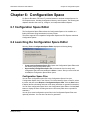
6.1 Configuration Space Editor
The Configuration Space Editor allows the Configuration Space to be modified on a
field-by-field basis using hexadecimal or binary format.
The editor supports PCI-compatible Configuration Spaces and PCI Express enhanced
Configuration Spaces.
6.2 Launching the Configuration Space Editor
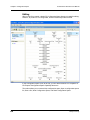
Selecting Tools > Configuration Space Editor displays the following dialog:
•
•
Create new Configuration Space File: Opens the Configuration Space Editor with
the default (empty) configuration space.
Open existing Configuration Space File: Activates the list of recently used
configuration space files and enables the Select... button. After you select a file and
click OK, the Configuration Space Editor opens.
Configuration Space Files
You can save configuration space files in the Configuration Space View (see
“Configuration Space View“ in the Summit T2-16 User Manual). Open a trace file, select
a packet, and then select Reports > Configuration Space View. Click the Save button
to display the Save As dialog and enter a file name (which has no special file extension).
You can save configuration space files in the Configuration Space Editor. Click the Save
button to display the Save As dialog and enter a file name (which has no special file
extension).
You can open saved configuration space files in the Configuration Space Editor and
optionally edit them. You can then use them for generation.
Teledyne LeCroy
61
Chapter 6: Configuration Space
Summit Z2-16 Exerciser User Manual
Editing
When a new file is created, a blank PCI Configuration Space Header is loaded for editing.
However, its position is not configurable, and the offset always starts at 000h.
In the Configuration Space View, at the left, you can add and define PCI-compatible or
PCI Express Configuration-Space Capability Structures.
The toolbar allows you to create a New configuration space, Open a configuration-space
file, Save a file, Write Configuration Space, and Read Configuration Space.
62
Teledyne LeCroy
Summit Z2-16 Exerciser User Manual
Chapter 6: Configuration Space
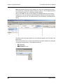
Click + Add and then choose a Capability Structure from the context menu. You can also
select Edit > Add PCI Capability or Edit > Add PCI Express Capability.
Available PCI Capability Structures are:
• Message Signaled Interrupts
• Accelerated Graphics Port
• Vital Product Data
• Vendor-Specific
• PCI Express
• Hyper Transport
• Generic
Available PCI Express Capability Structures are:
• Virtual Channel
• Virtual Channel for MFVC
• Device Serial Number
• Power Budgeting
• Root Complex Link Declaration
• Root Complex Internal Link Control
• Root Complex Event Collector Endpoint Association
• Vendor-Specific
• RCRB
• ACS
• MFVC
• Resizable Bar
• Multicast
• DPA
• ARI
• LTR
• SR IOV
• Generic
Selecting a structure displays a dialog in which you can define the structure.
Enter an integer Offset.
Position the structure in the linked list of capabilities by selecting the Previous and Next
capability structures.
Teledyne LeCroy
63
Chapter 6: Configuration Space
Summit Z2-16 Exerciser User Manual
Note: User-defined structures can be added to the above set of supported structures
(see Appendix A “Configuration Space Decoding” on page 71). The Configuration Space
View, from the Reports menu, reflects any added structures.
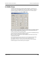
After you click OK, the center column displays the Capability Structure View, with the
register layout. You can modify the selected Capability Structure by selecting registers
and editing in binary or hex. The toolbar allows you to select Binary or Hexadecimal for
editing.
Alternatively, after selecting a register, you can modify the register in the Field View in the
right column.
The Field View allows you to override field attributes. By default, attributes are assigned
according to the specification. The available options are:
•
•
•
64
RO: Read Only
RW: Read-Write
RW1C: Write-1-to-Clear
Teledyne LeCroy
Summit Z2-16 Exerciser User Manual
Chapter 6: Configuration Space
6.3 BARs Setup
The BARs Setup dialog helps set up Base Address Registers. It provides a more
convenient way of defining BARs than setting up the BARs manually. In addition, it
provides the mapping of BARs to PETrainer and Summit Z2-16 memory regions.
To open the BARs Setup, select Edit > BARs Setup.
BAR1 and BAR2 are assigned to 64-bit memory address space and mapped to Mem64
PETrainer memory region. BAR4 is assigned to 32-bit memory address space and
mapped to Mem32A PETrainer memory region.
You can specify Prefetch and Address Space Size. The sizes for each address space are
limited to the values supported by PETrainer hardware.
BAR and Prefetch fields affect the Hexadecimal/Binary in the middle column of the
Configuration Space Editor.
Size field affects Field View in the right column of the Configuration Space Editor.
The mapping of BARs to PETrainer memory regions is discussed at the
AddressSpace Command in the Help section of the PETrainer Script Language.
The BAR settings are used for Memory and IO completer.
Teledyne LeCroy
65
Chapter 6: Configuration Space
Summit Z2-16 Exerciser User Manual
6.4 Configuration Read and Write
PETrainer™ can automatically handle Configuration Read and Write TLP transactions:
•
For a Configuration Read transaction, the Completion TLP contains the data
read from the internal Configuration Space according to specified register
address.
•
For a Configuration Write transaction, the address for the internal
Configuration Space is updated with the data taken from Configuration Write
TLP, and Configuration Write Completion is returned.
You can specify the initial Configuration Space by editing the AddressSpace=Write
command directly in the script or by using the UI provided in the Generator toolbar.
The PETracer™ software provides a special editor for editing this file called the
Configuration Space Editor (see “Launching the Configuration Space Editor” on page 61).
66
Teledyne LeCroy
Summit Z2-16 Exerciser User Manual
Chapter 7: Address Spaces
Chapter 7: Address Spaces
7.1 Memory/IO Space Editor
The Memory/IO Space Editor lets users write address space memory into the Exerciser
and read address space memory from the Exerciser.
To access the Memory/IO Space Editor, select Tools > Memory/IO Space Editor. The
following dialog opens:
•
•
Create new Address Space File: Opens the Memory/IO Space Editor and displays
an empty address space with the size specified.
Open existing Address Space File: Activates the list of recently used
Memory/IO Address Space files and enables the Select... button. After you have
selected a file and then clicked Select, the Memory/IO Space Editor opens.
The Memory/IO Address Space editor is implemented as a standard hex editor.
The address space memory must be saved to a file so that it can be downloaded to the
hardware using the PETracer™ application.
Teledyne LeCroy
67
Chapter 7: Address Spaces
Summit Z2-16 Exerciser User Manual
If you prefer, you can write address space memory into the Exerciser and read address
space memory from the Exerciser directly using the
and
toolbar buttons or using the menu File > Write Address Space or
File > Read Address Space.
7.2 Memory Region for Host Emulation
For Host Emulation, the Address Space mechanism on Summit Z2-16 does not support
defining memory regions. However, you can enable one 32-bit memory region for
Host Emulation by performing the following steps:
Step 1 Enable automatic Configuration and Memory/IO handling in the
Transactions tab of the Generation Options dialog.
Step 2 Create and load a configuration space with one BAR configured for
Mem32A with the desired size. For how to create a configuration space
file and define the BAR, see Chapter 6 “Configuration Space” on page
61.
After linking with the device DUT, the DUT can access the defined 32-bit host
memory region at fixed physical address 0x40000. The DUT can read back whatever it
wrote in those memory locations, or whatever was loaded there by the script using the
AddressSpace command.
68
Teledyne LeCroy
Summit Z2-16 Exerciser User Manual
Chapter 8: Updates and Licensing
Chapter 8: Updates and Licensing
8.1 Updating the Exerciser
BusEngine™ and/or Firmware updates are now automatic processes that run anytime a
new version of the PETracer™ software is installed that is incompatible with the currently
installed BusEngine or Firmware. The update process generates onscreen instructions.
If, however, you need to manually perform BusEngine or Firmware updates, follow these
steps:
Step 1 Select Setup > Update Device … from the menu to display the
Update Analyzer dialog box for Summit Z2-16™.
Step 2 Select the appropriate file locations for the Firmware and/or BusEngine,
using Browse, if necessary.
Step 3 Check the appropriate options (if in doubt, check all options).
Step 4 Click Update to initiate the updating of the Exerciser.
Teledyne LeCroy
69
Chapter 8: Updates and Licensing
Summit Z2-16 Exerciser User Manual
8.2 License Keys
A License Key is necessary to enable software maintenance. If you attempt to generate
traffic with the Exerciser without an installed License Key, a message appears to indicate
that a License Key is necessary in order to record traffic.
A License Key must be obtained from Teledyne LeCroy for each Exerciser.
After you obtain the License Key, follow these steps to install it:
Step 1 Select Help > Update License… from the menu bar. to display the
Update License dialog box.
Step 2 Enter the path and filename for the License Key or use the Browse
button to navigate to the directory that contains the License Key.
Step 3 Select the .lic file, and then click Update Device.
You can also update your licensing information by selecting
Setup > All Connected Devices …, then clicking Update License.
8.3 License Information
You can view Licensing information for your Exerciser by selecting
Help > Display License Information... from the menu bar. The License Information
window displays data about the maintenance expiration and purchased features.
70
Teledyne LeCroy
Summit Z2-16 Exerciser User Manual
Appendix A: Configuration Space Decoding
Appendix A: Configuration Space
Decoding
The decoded capability structures in the Configuration Space Viewer and Editor are
based on programmed definitions in the PETracer software and on Configuration Space
Decode Scripts.
Configuration Space Decode Scripts are tools to define capability structures and instruct
the Configuration Space Viewer or Editor how to decode them. These scripts are in the
\CfgSpaceScripts sub-directory below the \Scripts directory in the application directory.
You can write Configuration Space Decode Scripts using the CATC Scripting Language
(CSL). See the Teledyne LeCroy Analyzers File Based Decoding Manual for reference.
PCI Express Configuration Space Decode Scripts have the file extension .pecfgdec.
A.1 Mandatory Definitions
Configuration Space Decode Scripts must set the following reserved variables.
•
•
•
CapabilityName: Name of the capability structure
CapabilityID: ID of the capability structure
ExtAddSpace: Set to 1 if Extended Configuration Space.
Otherwise, set to 0 for PCI.
A.2 Mandatory Module Functions
Modules are collections of functions and data dedicated to decoding a specific capability
structure. Each module has one primary Configuration Space Decode Script file
(extension .pecfgdec) and optionally has include files (.inc).
A module function is an entry-point into a decoding module. To help display a
capability structure, the application calls a module function.
The Configuration Space Editor and Viewer support only the DecodeRegister( offset )
and GetSize( ) functions.
DecodeRegister( offset )
The application calls this function while decoding a specific DWORD offset of the
specified CapabilityID. The offset is the decoding entry point, where the decoding path
starts.
The Configuration Space Editor calls this function to determine how to decode the
assigned configuration space. The offset parameter is the DWORD to decode.
An offset of 0 indicates bytes 00h-03h, an offset of 1 indicates bytes 04h-07h, and so on.
Note: The Configuration Space Editor can only decode one DWORD at a time.
GetSize()
This function returns the size of the capability structure specified by CapabilityID.
Teledyne LeCroy
71
Summit Z2-16 Exerciser User Manual
Appendix A: Configuration Space Decoding
A.3 Configuration Register Types
The following reserved variables are defined global constants.
• CFGREG_UNDEFINED
• CFGREG_HWINIT
• CFGREG_RO
• CFGREG_RW
• CFGREG_RW1C
• CFGREG_ROS
• CFGREG_RWS
• CFGREG_RW1CS
• CFGREG_RSVDP
• CFGREG_RSVDZ
Note: These reserved variables match the Configuration Register Types of Table 7-2 in
Section 7.4 of the PCI Express Base Specification, Rev. 2.1.
A.4 Primitives
Decoding uses the following primitives.
GetRegisterField( dword_offset, bit_offset, field_length )
This function returns a register field of length field_length, starting at bit position
bit_offset in DWORD dword_offset.
•
•
•
dword_offset: DWORD offset of the register field location
bit_offset: Bit offset of the register field location
field_length: Length of the register field
For example, GetRegisterField( 1, 9, 2 ); means: Go to DWORD 1, bit offset 9, and
returns 2 bits.
Teledyne LeCroy
72
Summit Z2-16 Exerciser User Manual
Appendix A: Configuration Space Decoding
AddField( field_name, field_length, configuration_reg_type, tooltip,
encoding_table = NULL )
This function adds a register field to the Capability View and returns a pointer to the field,
for adding subfields.
•
•
•
•
•
•
field_name: Name of the register field to display in the Capability View
field_length: Length of the register field
configuration_reg_type: Configuration register type of the register field.
Note: If subfields are defined, their configuration register types override this setting
for their specified bits.
tooltip: Tooltip displayed for the register field in the Capability View
encoding_table: Optional. Displays encodings as lists for select values.
For example, user input becomes a combo box for the field in the Field View.
As examples:
AddField( "PCI Express Extended Capability ID", 16, CFGREG_RO, "" );
means: Add the field "PCI Express Extended Capability ID" with length 16 and cfg
register type CFGREG_RO.
capability_reg = AddField( "Capability Register", 32, CFGREG_RW, "" );
means: Added the field "Capability Register" with length 32 and cfg register type
CFGREG_RW and stored a pointer to this field in variable capability_reg, which can be
used to add subfields to this field.
AddSubField( parent_field, subfield_name, subfield_length,
configuration_reg_type, tooltip, encoding_table = NULL );
This function adds a subfield to a register field in the Capability View. Subfields are
modifiable and visible in the Field View and appear in the tooltips of register fields.
•
•
•
•
parent_field: Pointer to a register field in the Capability View
subfield_name: Name of the subfield, displayed in the Field View
subfield_length: Length of the subfield
configuration_reg_type: Configuration register type of the subfield field.
Note: This overrides the configuration_reg_type of the parent field.
• tooltip: Tooltip displayed for the subfield in the Capability View
• encoding_table: Optional. Displays encodings as lists for select values.
• For example, user input becomes a combo box for the field in the Field View
.
For example,
AddSubField( capability_reg, "Mode Supported", 4, CFGREG_RO, "Indicates the
Function modes," ), ModeEncodings );
means: Add the subfield "Mode Supported" to the parent field "capability_reg" with length
4, type CFGREG_RO, a tooltip in the Capability View, and a combo box displaying "mode
encodings" for input in the Field View.
A.5 Helper File
ConfigSpaceCommon.inc include file contains useful functions for script decoding.
Teledyne LeCroy
73
Summit Z2-16 Exerciser User Manual
Appendix B: China Restriction of Hazardous Substances Table
Appendix B: China Restriction of
Hazardous Substances Table
The following tables are supplied in compliance with China's Restriction of Hazardous
Substances (China RoHS) requirements:
Teledyne LeCroy
74
Summit Z2-16 Exerciser User Manual
How to Contact Teledyne LeCroy
How to Contact Teledyne LeCroy
Type of Service
Call for technical support…
Contact
US and Canada:
1 (800) 909-7112
Worldwide:
1 (408) 653-1260
Fax your questions…
Worldwide:
1 (408) 727-6622
Write a letter…
Teledyne LeCroy
Protocol Solutions Group
Customer Support
3385 Scott Blvd.
Santa Clara, CA 95054-3115
USA
Teledyne LeCroy
Send e-mail…
[email protected]
Visit Teledyne LeCroy’s
web site…
teledynelecroy.com
75
Summit Z2-16 Exerciser User Manual
How to Contact Teledyne LeCroy
[This page intentionally blank.]
Teledyne LeCroy
76
Summit Z2-16 Exerciser User Manual
Index
Symbols
.lic files 70
.peg files 34
.peg traffic generation files 29
Numerics
25-pin Data Output Connector 12
A
AC Connector 11
address 75
Address Space Size field 65
address spaces 67
All Connected Devices command 70
application 13
Automatic ACK/NAK DLLP generation for received
TLP packets 51
automatic generation 27
B
BAR field 65
BAR settings 65
Bars Setup dialog box 65
BARs Setup... button 65
Base Spec Rev. 1.0 Compatibility Mode 51
blue highlight 36
BNC Connectors 11
brown highlight 36
BusEngine update 69
C
Capability Structure View 64
Capability Structures 63
CATC Technical Support 75
collapse 36
Command Properties window 34, 38
Comment 58
Completion TLP 66
Teledyne LeCroy
Index
Configuration Read 66
Configuration Space 61, 66
editing 62
Header 62
Configuration Space Editor 61, 66
command 61
Configuration Write 66
configuring
Exerciser 27
Connect macro 55
restoring 59
contact 75
Context menu 36
controls
Exerciser EML 9
Create new Address Space File 67
Create new Configuration Space File 61
creating
script 31, 33
Ctrl+N command 33
Current script position field 53
D
Data Output Connector 12
Device Emulation 51
Direction 31
Disconnect macro 55
restoring 59
Display License Information command 70
Do not export hidden packets 31
Do not export Idle packets 31
Do not send TLP packet if credit amount is
insufficient 51
E
Edit as Text command 34
Edit Code 58
Edit code... button 57, 58
Edit Generation Macro Icon dialog box 57
Edit Icon... button 57
editing
macros 58
script 36
electrical idle 27
e-mail 75
Email CATC Support 75
Enable Automatic Skip Generation 51
Enable Outlining 40
Error Log 34, 39
77
Index
Errors 39
Ethernet Port 11
executing 53
Exerciser 8
configuring 27
expand 36
Export Wait for ACK from upstream 32
Export Wait for Cpl from upstream 32
exporting
Trace to a Traffic Generation File 31
F
fax number 75
Field View 64
File Export dialog box 31
File Tabs 39
File tabs 34
Firmware update 69
flow control 28
Flow Control tab 51
From 31
front panel 9
fuse 11
G
Gen2 PCI Express 16-lane advanced verification
system 3
General page 51
Generate menu 55
generating 27, 53
theory 27
Generation Macro command 58
Generation Macros command 56
Generation Macros dialog box 56, 58
Generation Options command 40, 51
Generation Options dialog box 40, 51
GenScriptMacros directory 57
Go to Script Editor 37
H
hardware 3
Host Emulation 51
host machine 7
I
Summit Z2-16 Exerciser User Manual
Include statement 29
Include statements 39
InitFC State 54
Install Software command 13
Integrity tab 51
Intellisense 36
interface 13
Interposer options 51
K
Key
License 70
L
Layout 34
LeCroy PETracer command 13
LEDs
Exerciser EML 9
license files 70
License Information window 70
License Key 70
licensing information 70
Link Connect toolbar button 27
Link State 54
Link tab 51
link training 28
Link Training sequence 27
Linkup.peg file 52
List values 36
log 39
M
macros 55
changing order 58
creating 56
deleting 59
editing 58
Manual Action button 10
Memory/IO Space Editor 67
Microsoft® Windows®-based host machine 13
N
Name 58
New button 56
New PETrainer Script 33
Icon 58
idle 27
Include files 32
78
Teledyne LeCroy
Summit Z2-16 Exerciser User Manual
O
Offset field 63
Open existing Address Space File 67
Open existing Configuration Space File 61
opening
program 14
outlining 36
overview 3
P
PCI Configuration Space Header 62
PCI Express 16-lane advanced verification system
3, 5
Periodically schedule UpdateFC DLLP 51
PETracer
setting up 15, 18
PETracer EML
opening 14
PETracer ML
opening 14
Position Trace view on packet x 37
Power indicator LED 9
power on/off switch 11
power socket 11
Prefetch field 65
product
overview 3
program
opening 14
progress 28
R
Real-Time Statistics window 54
rear panel 11
restoring
icons 59
Resume Generation button 53
RS-232 25-pin Data Output Connector 12
S
Save all included files 32
saving
script 32
script 53
creating 31, 33
editing 36
executing 28
macros 55, 56
Teledyne LeCroy
Index
running 52
saving 32
script comment 56
Script Edit Window 36
Script Edit window 34
Script Editor 30, 34
toolbar 35
tooltips 36
Script Editor button 34
Script Editor toolbar 34
script icon 56
script name 56
Script properties area 56, 58
scripts 27
servicemarks ii
Show icon on the toolbar 58
Show Line Numbers 40
Show Tooltips 40
Size field 65
software
installation 13
update 69
Start generation button 28
Start menu 13
Start Traffic Generation button 53
Statistics Accumulation area 54
Status Bar
macros 55
Status bar 28
Stop Generation button 53
Summit Z2-16 3, 7, 8
Summit Z2-16 Exerciser
to DUT 19, 23
summit.sys driver 13
support 75
Sync In Connector 11
Sync Out Connector 11
T
Technical Support 75
telephone number 75
testing 27
theory 27
TLP transactions 66
To 31
To Analyzer connector 9
to Generator File Format 31
Toggle Outlining 40
Trace Viewer 14
trademarks ii
79
Index
Summit Z2-16 Exerciser User Manual
traffic
generating 27, 53
traffic generation
macros 55
traffic generation files 31, 34
traffic generation prep 52
U
Update Analyzer dialog 69
Update command 69
Update Device command 69, 70
Update License command 70
Update License dialog box 70
updates 69
USB drivers 13
USB Type B Host Computer Connector 11
User input 28
V
View Options 35
View Options button 40
Viewer 14
W
Wait commands 28
Warnings 39
web site 75
Website, CATC 75
whether or not to show script icon 56
80
Teledyne LeCroy