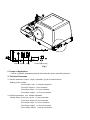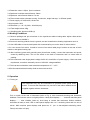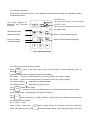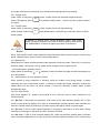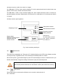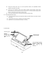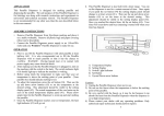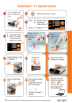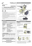
1
MH-455 Automatic Microtome Standard Setting List No. Item Quantity 1 Main Machine 1 Set 2 Hand Wheel 1 Piece 3 Knife Support 1 Piece 4 Cassette Clamp 1 Piece 5 Scrap Trough 1 Piece 6 Blade 1 Box 7 Hexagonal Wrench (4#) 1 Piece 8 Hexagonal Wrench (5#) 1 Piece 9 Power Line 1 Piece 10 Fuse Tube (5A) 4 Pieces 11 Lubrication 1 Bottle Moss Instruments Co., Ltd. Date: Registration No.: LS (Shi) YJX (Zhun) Zi 2009 No.1410018 Executive Standard: MH-455 YZB/LS 0010-2009 Automatic Microtome User Manual Moss Instruments Co., Ltd. No. 5 Hepanxiang, Jinhua, Zhejiang, China 321001 TEL: 86-579-8237 3070 FAX: 86-579-8353 3099 www.mossinstruments.com Contents Profitable Suggestions:......................................................................................................................................... 1 1. Introduction ......................................................................................................................................................... 4 2. Scope of Application ......................................................................................................................................... 6 3. Technical Parameter .......................................................................................................................................... 6 4. Working Conditions ........................................................................................................................................... 7 5. Operation .............................................................................................................................................................. 7 5.1 Turning on .................................................................................................................................................... 7 5.2 Hand panel operation................................................................................................................................. 8 5.3 Sectioning arm prompt............................................................................................................................... 8 5.4 Normal section (or trim) operation prompt .............................................................................................. 8 5.5 Error code prompt....................................................................................................................................... 9 5.6 Main machine panel operation ............................................................................................................... 10 6 Parts adjustment.................................................................................................................................................11 6.1 Specimen holder and orientation system ...............................................................................................11 6.2 Box shaped specimen clamp. .............................................................................................................. 12 6.3 Knife holder .......................................................................................................................................... 12 6.4 Hand wheel. ......................................................................................................................................... 13 7. Normal Troubles Solving Methods .............................................................................................................. 13 8. Cleaning and Maintenance.......................................................................................................................... 14 8.1 Cleaning up the instruments ................................................................................................................... 14 8.2 Lubricate instruments............................................................................................................................... 15 9. Notices ................................................................................................................................................................ 16 Profitable Suggestions: The user should read this user manual carefully before installation and operating the machine. Check your power socket is well grounded. Blade is sharp, beware when you change it. Do not place blade anywhere with the cutting edge facing upwards. Before changing specimens always lock the hand wheel and cover the knife edge with the knife guard. Do not put instrument under extreme temperature and high air humidity environment. Failure to follow this will cause instrument severe damage. Please keep instrument far away from fire. In case of malfunction, contact our company. Don’t try to solve it by your own risk. 1. Introduction Model MH-455 paraffin microtome is the national regulated first class medical equipment. It is a device used for human and propagation tissues pathological section analysis. It is used to cut paraffin embedding specimens, thin section mounted specimens. It can be widely used for pathological diagnosis analysis and research in hospitals, medical colleges, legal medical experts and propagation institutes. The instrument mainly consists of the following features: 1. Adopt to microchip plus photo electricity signal checking control technology; 2. Step motor controls precisely specimen feeding value; 3. LED screen on hand control panel is to display section/ trimming value and status; 4. LED screen on main machine is to display section/trimming total pieces, section/trimming total thickness, retraction and other information. 5. Self error checking function is easy for user check error; 6. Hand wheel locking structure is to protect user safety, it equips with signal checking system; 7. Emergency stop knob is to protect user and instrument; 8. Foot switch is optional accessory and easy for user doing operation General overview: Cover Orientation system Cassette Clamp Main machine Panel Knife holder Base plate Control Panel Fig. 1 Handwheel Locking lever Lever for knifer holder moving Waste tray Fig. 2 Fuse Switch Plug Control panel plug Fig 3 2. Scope of Application Used to cut paraffin embedded specimen and make thin section mounted specimens 3. Technical Parameter 3.1 Section thickness: 0.25μm -100μm, adjustable. (3-5μm is the best result) Setting values: 0.25μm From 0.50μm -5μm in 0.50μm increments From 5μm -20μm in 1 μm increments From 20μm -60μm in 5 μm increments From 60μm -100μm in 10 μm increments 3.2 Trimming thickness: 1μm - 600μm adjustable Setting values: From 1μm -10 μm in 1μm increments From 10μm -20μm in 2 μm increments From 20μm -50μm in 5 μm increments From 50μm -100μm From 100μm -600μm in 10 μm increments in 50 μm increments 3.3 Retraction value: 0-95μm, 5μm increments 3.4 Specimen horizontal travel distance: 28mm 3.5 Specimen vertical travel distance: 70 mm 3.6 Three modes under automatic running: Continuous, single and step; 11 different speed; 3.7 Power supply: AC 220V±22V; 50Hz±1Hz 3.8 Input power: 50W 3.9 Dimension: (L × W × H) 560 × 400×290 (mm) 3.10 Total weight: about 35kg 3.11 Working noise: less than 65dB (A) 4. Working Conditions 4.1 Remove package and put microtome on the experiment stable working table; adjust rubber knobs under bottom to stabilize it; 4.2 Prevent it receiving quakes from the ground, and don’t install other vibrating equipments round it. 4.3 Use USB cable to connect hand panel with communication port on the back of main machine. 4.4 If user choose foot switch, it needs to connect foot switch cable plug to socket on the rear of main machine, and tighten locking cap. 4.5 After confirming power with grounding wire (three holes socket), connect the instrument and power socket by attaching wires. Turn on the switch on the back of instrument and it is under state of working. 4.6 This instrument uses single-phase voltage 220V±10% and 50Hz AC power supply. If does not meet requirement, it needs to externally connect 100VA AC voltage stabilizer. 4.7 The instrument should be used at ambient temperature +4℃~+35℃. 4.8 Environmental relative humidity shall not be more than 80%. 5. Operation 5.1 Turning on . The instrument may only be connected to a grounded mains power outlet socket. To connect the instrument only use one of the mains cables that are supplied together with the instrument Turn on switch at the rear of instrument (refer to Fig 3), after instrument buzzing and instrument initializes. The feed arm return to original position. Hand panel displays “- - - “ and main machine panel displays “- -“. After initialize, follow by short beep to remind that instrument finishes initialize. Instrument is ready to work. LED on hand panel displays with “xx.x” sectioning value and is in unit of micron. Main machine panel displays total pieces as “0”. (xx.x is last adjusted sectioning value. Factory-set value is 5.0μm). 5.2 Hand panel operation Layout of this instrument is as Fig. 4. LED displays working mode and setting value separately. Below is operational buttons. LED TRIM (red) Lights up when trimming mode is activated LED screen displays for sectioning and trimming thickness LED SECT (red) Lights up when sectioning mode is activated Button to increase/ decrease thickness Top speed button Speed select knob Button for select sectioning mode Button for feeding forward/baclward Button to Start motorized sectioning Fig. 4 Hand panel layout 5.2.1 Sectioning and trimming mode switch Press trimming TRIM SECT mode. button on the right upper corner of hand panel to choose sectioning mode or Instrument default mode is sectioning model after initializing. 5.2.2 Press “ + “button to increase sectioning or trimming value in the range of setting. 5.2.3 Press “ - “button to decrease sectioning or trimming value in the range of setting. 5.2.4 When pressing “ “ , sectioning arm goes backward. 5.2.5 When pressing “ “ , sectioning arm goes forward. 5.2.6 Select section mode MODE Press “MODE”, automatic section mode will switch among “Single-Step-Continuous” three mode. Under certain status, corresponding LED indicator will light up. 5.2.7 RUN When the instrument is carrying on “RUN“ operation, system starts to do relative sectioning mode according to advance setting. 5.2.7.1 CONT. mode Under “CONT.” mode press button, system comes into automatic continuous sectioning RUN mode. LED lights up at the same time to indicate working status. Press this button again, LED light off ,system receives stop command, but it will finish last sectioning then stop working. 5.2.7.2 SING mode Under “SING.” mode press button, system comes into automatic single sectioning RUN mode. LED lights up at the same time to indicate working status. Press it one time, system sections one piece. 5.2.7.3 STEP mode Under “SING.” mode press button, system comes into step sectioning RUN mode. System continuously sections until release button. LED lights up at the same time to indicate working status. If machine is working under normal automatic “CONT” and “SING” mode, encounter emergency and need to stop sectioning, please press red “EMERGENCY” knob on the upper right corner of microtome . 5.2.8 TOP SPEED Press “TOP SPEED” button under automatic continuous section status, system sections or trims at top speed. Release button, system returns normal setting speed. 5.2.9 Speed knob Speed knob is to select sectioning speed under automatic continuous mode. There are 11 levers from lowest to fastest. During fully running, speed cannot change until next working circle. 5.3 Sectioning arm operation prompt When system is performing “ “ or “ “operation, hand box makes long beep to remind sectioning arm up to limit position. 5.4 Normal section (or trim) operation prompt When system is doing sectioning or trimming, hand box makes a long beep prompt, it means sectioning arm up to forward limit position. If continue to rotate hand wheel, hand box continuously makes alarm but arm does not move forward. If under full automatic working status, system automatically stops. 5.5 Error code prompt LED screen displays “E*” signal to give prompt of error. User may refer to below instruction to do trouble shooting. 5.5.1 E0 error: If after switch on instrument, LED screen on the main machine displays “E0” or LED screen on the hand box displays ”E0”, there is communication problem between main machine and hand box. Please switch off power first, and then re-plug cable tightly. Switch on power again. 5.5.2 E1 error: If LED on main machine displays E1, emergency stop knob is in down state. Please clockwise turn emergency stop knob one time, trouble is resolved. 5.5.3 E2 error: If LED on main machine displays E2, under full automatic working state, electronic motor controller temperature is too high and motor protection against overheat occurs. Please keep microtome stop for a while, then switch on it again. 5.5.4 E3 error: If LED on main machine displays E3, which means hand wheel is locked when user presses “RUN” button. Please unlock hand wheel. 5.5.5 E4 error: If LED on main machine displays E4, which means electronic motor is overload or protection against overheat. Please switch off microtome for a while (about 10-15 minutes) and switch on it again. 5.6 Main machine panel operation Total pieces indicator Displaying Screen Total thickness indicator Retraction indicator Setting indicator Clear Button To reset section counter and section thickness sum back to 0 Display Mode Switches between section thickness sum and section counter. Fig. 5 main machine panel layout 5.6.1 Mode button This button may repeatedly use. First press it, ∑n indicator lights up and LED screen displays number of total previously completed section. The instrument automatically adds on number. Second time press it, ∑μm indicator lights up and LED screen displays number of total thickness in μm. Number automatically changes according to thickness of per piece and total pieces. When the instrument is switched off using the main power switch, both values (section thickness sum and section number) are erased from memory. 5.6.2 Clear button Press Clear button to reset section thickness sum or section number back to 0. 5.6.3 Retraction Press DISPLAY MODE and CLEAR buttons simultaneously to call up the retraction function. The retraction value can be adjusted by using “ +” and “ - ” button on the main panel in increments of 5μm to maximum of 95μm. After reset, press CLEAR button to confirm desired retraction value. While the specimen is in retraction, the red LED on the RETRACT lights up. 6 Parts adjustment 6.1 Specimen holder and orientation system Orientation system Specimen holder clamp Knife holder Scale for positioning Fig 6 Vertical k b Orientation Pull eccentric rod to lock or release specimen box Lock and loose specimen holder clamp Locking lever Horizontal Orientation knob Fig 7 Fig 8 Turning the locking lever (Fig 7) to set the specimen holder to the adjustable release condition and section lock status. Turning the two orientation knobs under release condition make specimen holder clamp plane defluxion by pass horizontal axis and vertical axis for ensuring required tangent plane location to decide the required plane cutting location. 6.2 Turning the adjustable lever to lock and loose specimen holder clamp Box shaped specimen clamp. Turning the spanner (Fig 8) on the specimen clamp can make the jaw in the state of braced and locked. The specimen can be put in or take off in the state of braced. Specimen box may be placed horizontally or vertically. 6.3 Knife holder Protective guard Release adjustable lever to move knife holder left and right Pull knob to lock and loose blade Use #4 hexagon spanner manually rotate the knife holder to adjust slice angle, scale is for reference Fig 9 To turn the adjustable lever under knife holder to release and lock knife holder base. In release conditions you can make the knife holder base do the back and forth movement by hand to choose latched position needed. There is a scale under knife holder for reference by location. Use hexagon spanner to turn the eccentric rod in the hole on the right side of the knife holder to release and lock the rotator of the knife holder. In release condition you can move the rotator by hand to choose locked cutting angle needed. There is a scale on the right side for reference by location. Turn adjustable lever on the rotator to release and lock knife clamp. In release condition you can make the knife clamp do the left-and-right movement by hand to choose latched position needed. Turn adjustable lever on the knife clamp to release and lock knife flat. You can put in or take off the knife in release conditions. Take off the knife after finish the work. The protecting plate shall be on the installed position when the knife is on the knife clamp. 6.4 Hand wheel. Hand wheel locker. Spanner may lock at top position Hand wheel can be released or locked status. Hand wheel can be locked at a specific position when the spanner on the hand wheel is turned. Turn the eccentric rod handle under hand wheel to lock that at any position. Where there is a solid circle is locked, where there is hollow circle is rotatable. 7. Normal Troubles Solving Methods There are normal problems in the following table which are likely to happen when the instrument is used. Besides, there are some possible causes that lead to these problems happened and solving methods. Trouble Reason Solving Methods 7.1 Possible phenomena 1. The section is uneven. The knife centre gripping is fasten knife again The thin and thick section is alternate, sometimes even it if doesn’t improper. Knife is dull Pressure plate is broken or cutaway. adjustment isn’t right. The cutting angle of the knife is too less. Move the knife holder lateral or stick in new knife. Change new holder plate, or use new knife holder Readjust holder plate Increase the cutting angle gradually until find the optimum 2. The section is congestion and compressive. Use the other part of the knife or a Knife dull The sections congestion. There is the phenomenon of Specimen temperature is high Cutting speed so fast. crease and nip. new one. Make the specimen cool before cutting. Reduce the cutting speed. 3. There is fringe in the On the pressure plate is filling up section. paraffin on the back of the knife Clear up this regional paraffin. holder. Turn hand wheel with a rather slow speed. Decrease 4. There is noise when cutting. the cutting angle The knife will shake and sound Cutting speed too fast. gradually until find the optimum when The cutting angle is too big. one. cutting some hard specimen. There is pull or Clip of specimen or knife not fixed. slightly frictional make on the Check all the screwed and jaw connection in the specimen rest and knife. knife holder system. If necessary, fixture the control rod and screw. 7.2 Instrument failure 1. No section is cut when ● The specimen has reached to the turn the hand wheel. extreme position. Press “back” key to make the specimen backward and so the knife holder. Adjustment the cutting speed or 2. Knife service time is The power for section is too short strong. the section thickness in process of cutting. Choose smaller section thickness or slow down speed of turning hand wheel. 8. Cleaning and Maintenance. 8.1 Cleaning up the instruments 8.1.1 Conduct the following steps before cleaning each time: the Turn up the specimen grip to the top and lock the hand wheel. Release the specimen grip and pull it out. Pick off the knife from the knife holder and put it back to the knife box. Dismount the knife holder and its seat to clean up. Take down the specimen from the specimen nip. Clear away the section waste with dry brush. Take down the specimen grip to clear up separately. 8.1.2 Instruments and external surface: If necessary, the external painted surface can be cleaned with light-duty commercial housework cleaner or suds. And then use wet cloth rub it until dry. You may use the substitute of xylene, paraffin oil, paraffin scavenger to erase residual. The instruments must be dry when use again. 8.1.3 Knife holder Please according to following steps to clean up the knife holder if it had been dismounted. Downwardly turn over the cutting edge cover sheet. Turn the eccentric rod handle in the lateral of the body of revolution and draw it out from sideward. Push the knife clamp back which have knife clip and shift it out from the rotary unit. Turn the eccentric rod handle in the lateral of the knife clap and draw it out from sideward. Dismount the knife clamp. Clean up all parts of the knife holder. Don’t use xylene or alcoholic liquid (e.g.: glass cleaner) when clean up paraffin. Make the knife holder dry and assemble it together. Apply to thin layer of lubrication after clean up the parts which had been taken off. When fix the knife clip, make sure that its upper part is parallel with the back edge of the knife clamp seat. 8.1.4 Box shaped specimen grip Dismount the box shaped specimen grip to clear away the residual paraffin. Don’t use xylene or alcoholic liquid to clean up. Use the substitute of xylene or paraffin scavenger. You can put the box shaped specimen grip into oven to heat it to 65℃ until lipid paraffin bleeding off. Wipe off paraffin with dry cloth. Apply oil to the axis grasping joystick after using oven heating method. 8.2 Lubricate instruments. Do oil lubrication for the following parts monthly. (1~2 drop is well enough Instruments and specimen holder Grip draw in the clamp. Lock in iron at the “T” knife clap back of the microtome bedplate. The knife holder slide way on the microtome bedplate. Knife holder Lock in iron at the “T” body of the rotary units on the knife clamp seat. The knife control grip is shift to the eccentric rod handle. The iron locking head on the knife clamp of the ”T” body of rotary unit and the knife holder with slide way. The grasping joystick of the knife. Box shaped specimen grip The bearing of the grasping joystick. 9. Notices Must grasp the specimen before positioning the knife. During the operation locking hand wheel and cover the knife edge with its cover sheet. Be most careful when you take the section knife. It is possible to lead to bad hurt because of the sharp cutting edge. You should turn the hand wheel with the same speed during the cutting process. The hand wheel turning speed must suit with the hardness of the specimen. Harder specimen use slow speed. Locking hand wheel and covering the knife edge with its cover sheet when changing specimen piece. The instrument should be positioned on the experiment work table level and stable. Preventing it from quake from the ground, and don’t put other equipments which may produce vibration near the instrument. Holding the fore and end trough of the back when moving it and don’t hold the other parts like hand wheel handle. Periodically cleaning the instrument. Locking the hand wheel before cleaning. Don’t use acetone or xylene liquid to clean up the instrument. Make sure that no paraffin comes into the inside of machine during the cleaning. Please follow the safety warnings of the manufacture when using cleaning solvent. Put the hand wheel on the locking position when turn down the instrument. Electronic parts be repaired by professionals and other people do not touch them.