1
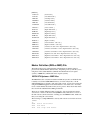
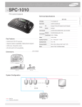
User Manual
Knee Alignment Device
By Motion Lab Systems, Inc.
Released: May 6, 1998
1st Printing (revised June 21, 2011)
This manual, or parts of it, may be copied for use with the Knee Alignment Device manufactured by Motion Lab
Systems, if all copies contain this notice and all copyright notices. This manual, or parts thereof, may not be used with
Knee Alignment Devices manufactured by any other company and the descriptions within this manual may not apply to
devices manufactured by other companies. While every effort has been made to ensure that the information contained
within this manual is accurate, Motion Lab Systems, Inc., can not assume responsibility for any errors contained within
this document.
The Motion Lab Systems Knee Alignment Device was developed by Motion Lab Systems, Inc., for use with the
Newington Software and the VICON Clinical Manager® program.
VICON Clinical Manager is a product of Oxford Metrics Ltd., who can be contacted at 14 Minns Estate, West Way,
Oxford, England, OX2 0JB. Questions regarding the function and operation of the VICON Clinical Manager software
should be directed to Oxford Metrics Ltd.
AMASS is a registered trademark of Adtech, Adelphi, Maryland, USA
VICON and VICON Clinical Manager are registered trademarks of Oxford Metrics, Ltd., UK.
© Motion Lab Systems Inc., 1998, 2011
All Rights Reserved
Printed in the United States of America
Motion Lab Systems
15045 Old Hammond Highway,
Baton Rouge, Louisiana 70816
+1 225 272-7364
[email protected]
http://www.motion-labs.com
Contents
Introduction
2
When to use a Knee Alignment Device ..................................................................................... 2
The KAD Environment .............................................................................................................. 3
Repair of your KAD .................................................................................................................. 3
KAD Placement
4
Defining the Flexion Axis.......................................................................................................... 4
Editing the Appropriate Files
6
Configuration Files .................................................................................................................... 6
VICON Clinical Manager CFG file ............................................................................. 6
Marker Definition (DES or MKR) File ....................................................................... 7
Joint Axis Determination
10
Using VICON Clinical Manager ............................................................................................. 10
Basic Rotation Alignments ........................................................................................ 10
Thigh and Tibial Markers .......................................................................................... 10
Recognizing Errors in Hip Rotation .......................................................................... 11
Knee Joint Center Position ........................................................................................ 11
Knee Alignment Device ............................................................................................ 11
Ankle Joint Kinematics ............................................................................................. 12
Processing Data in VCM
14
"I Used a KAD, Now What" .................................................................................................... 14
The Session Form ...................................................................................................... 14
The Cycles Window .................................................................................................. 15
Checking for Errors in KAD Use
17
The Static Trial ........................................................................................................................ 17
The Dynamic (walking) Trial .................................................................................................. 18
Using Vicon-Nexus
20
KAD usage with Vicon software ............................................................................................. 20
Tibial Torsion ............................................................................................................ 20
Marker Size ............................................................................................................... 20
User Manual – MLS Knee Alignment Device
Contents • 1
Introduction
When to use a Knee Alignment Device
The purpose of the Motion Lab Systems Knee Alignment Device (also known as a
“KAD”) is to allow the VICON Clinical Manager software application from Oxford
Metrics Ltd., (VCM) to automatically establish the knee flexion axis during a static
trial. These devices are supplied in sets of two units, each looking like the
illustration below. The devices are generally used in pairs, one on each leg.
The Knee Alignment Device is a spring-loaded metal jig that fits gently over the
subjects’ knee while a static calibration data collection is performed. The design of
the Knee Alignment Device is such that the absolute distance between all three of the
markers on the device is identical (5.66 inches).
The design of the Motion Lab Systems KAD enables the VICON Clinical Manager
software to establish a virtual knee marker at the central joint of the Knee Alignment
Device and this, combined with the KAD wand marker, enables the knee flexion axis
to be measured.
User Manual – MLS Knee Alignment Device
Introduction • 2
A C3D (Coordinate 3d Data) file
When the VICON Clinical Manager software finds marker labels for a Knee
contains the 3D marker locations of the
Alignment Device defined in the C3D file, it uses the orientation of the three markers
KAD and other subject markers.
on the Knee Alignment Device to establish the knee flexion axis.
After the knee flexion axis has been established, VICON Clinical Manager calculates
the relative transverse alignment of this axis, to the transverse plane orientation of
the thigh and shank, as calculated using the mid-thigh and mid-shank stick markers.
These relative alignments are stored in the subject’s Session form as Thigh and
Shank Rotations and are applied to all dynamic data within the session. Thus the
correct alignment of the thigh and shank wands becomes less critical as any minor
alignment errors are measured during the static trial and can be automatically
removed during the processing of the dynamic trials. Please refer directly to the
Oxford Metrics VCM User Guide or contact the manufacturer for information on the
kinematic processing that is performed within the VICON Clinical manager software
program.
A Knee Alignment Device should be used only during a static trial. The
thigh and shank rotation offset values calculated in VICON Clinical Manager are
used to align the knee and ankle flexion axes during the dynamic trials.
Please do not attempt to use the Knee Alignment Device during a dynamic or
walking trial as it has not been designed to be worn while the subject is walking.
The KAD Environment
When a Knee Alignment Device is used during a static trial, the VICON Clinical
Manager software assumes that the knee and ankle flexion axes are parallel. The
Knee Alignment Device defined ankle flexion axes will lie parallel to the knee
flexion axes and will pass through the lateral malleolus marker.
For some individuals this is incorrect, therefore this built-in assumption may be
overwritten, if desired by entering the subject's tibial torsion measurement directly
into the VICON Clinical Manager Session Form prior to processing the static trial
causing VCM to rotate the ankle flexion axes during its kinematics calculations.
Please note that an external tibial torsion measurement must be entered into
the VICON Clinical Manager Session Form as a negative value.
Repair of your KAD
The Motion Lab Systems, Inc., KAD is a precision device that should give you many
years of trouble free service. However, it is possible that it may become worn or
damaged during use. Please contact Motion Lab Systems for service or exchange of
any damaged Knee Alignment Device.
User Manual – MLS Knee Alignment Device
Introduction • 3
KAD Placement
Defining the Flexion Axis
The placement of the Knee Alignment Device defines the flexion axis of the knee
and the ankle for the VICON Clinical Manager software so correct positioning of the
device is essential if these two axis are to be measured correctly by the VICON
Clinical Manager.
The soft, hollow, outer pad of the Knee Alignment Device jaw is placed directly over
the lateral surface intersection of the knee flexion axis and the inner pad is placed on
the medial aspect of the knee, close to or over the medial epicondyle.
When the knee is fully extended,
particularly in the adult knee, the fibrous and
fatty covering of the lateral joint capsule
tends to push the lateral pad of the Knee
Alignment Device forward, internally rotating
the measured knee flexion axis. This must be
avoided by adjusting the Knee Alignment
Device position to reflect the correct knee
axis.
The alignment of the Knee
Alignment Device stem with the knee flexion
axis must be thoroughly checked. While the
medial and lateral epicondyles of the knee
provide a good approximation for the correct
positions of the Knee Alignment Device pads
in normal adult knees, in abnormally shaped
knees, these landmarks may not represent the
optimal positions for the pads.
User Manual – MLS Knee Alignment Device
KAD Placement • 4
The alignment of the Knee Alignment Device stem with the knee flexion
axis must be thoroughly checked. While the medial and lateral epicondyles of the
knee provide a good approximation for the correct positions of the Knee Alignment
Device pads in normal adult knees, in abnormally shaped knees, these landmarks
may not represent the optimal positions for the pads.
Always check the position of the Knee Alignment Device immediately prior
to data collection. The Knee Alignment Device could slip if the subject moves
between placing the device on the subjects knee and collecting the data. If the Knee
Alignment Device is not in the correct position during a static trial, there is no way to
correct the data acceptably.
User Manual – MLS Knee Alignment Device
KAD Placement • 5
Editing the Appropriate Files
Configuration Files
In most cases your motion capture system will have been set up with the correct
configuration files when it was installed. If this is the case then you can probably
skip this chapter. This section is useful for anyone installing a copy of VICON
Clinical Manager themselves, anyone who did not purchase the Knee Alignment
Device at the same time as VICON Clinical manager, or anyone who is upgrading
their data collection system.
Before you can process data collected with the Motion Lab Systems Knee Alignment
Device you must first configure your data collection system, as well as your copy of
the VICON Clinical Manager software, so that it knows what marker labels you will
be using to identify the Knee Alignment Device markers. This information will
usually need to be entered in two places. Once in the VICON Clinical Manager
configuration file (CFG File) and again in your motion capture systems’ Marker
Definition file (MRK or DES file).
It is most important that you take care to use identical marker labels and names in
both files otherwise the system will not work.
VICON Clinical Manager CFG file
<L/R> means either Left or Right side In general, the three markers on each Knee Alignment Device are identified
markers.
internally by VICON Clinical Manager through the Marker group in the CFG file as
<L/R>KAX or KNE, <L/R>KD1, and <L/R>KD2. Each Knee Alignment Device
marker in the C3D file should have a unique marker label assigned to it. However, as
there are no knee markers present during a Knee Alignment Device static trial, the
same label can be used for both the knee markers, <L/R>KNE, and the Knee
Alignment Device stem markers, <L/R>KAX. Both assignments must be present in
the Marker group in the CFG file.
When the VICON Clinical Manager software detects the presence of the Knee
Alignment Device markers in a three-dimensional data file, it recognizes the
presence of Knee Alignment Device(s). As knee markers cannot be present at the
same time as Knee Alignment Device s, the program assigns the shared labels to the
Knee Alignment Device stem marker(s).
Clearly, it is important that the labels assigned to the other Knee Alignment Device
markers, <L/R>KD1 and <L/R>KD2, are not shared by any other markers.
User Manual – MLS Knee Alignment Device
Editing the Appropriate Files • 6
[Markers]
SACR=sacr
{ Sacral wand }
LASI=lasi
{ Left ASIS marker }
LTHI=lthi
{ Left thigh wand }
LKNE=lkne
{ Left knee marker }
LTIB=ltib
{ Left shank wand }
LANK=lank
{ Left ankle marker }
LTOE=ltoe
{ Left toe marker }
RASI=rasi
{ Right ASIS marker }
RTHI=rthi
{ Right thigh wand }
RKNE=rkne
{ Right knee marker }
RTIB=rtib
{ Right shank wand }
RANK=rank
{ Right ankle marker }
RTOE=rtoe
{ Right toe marker }
LHEE=lhee
{ Left heel marker - static only }
RHEE=rhee
{ Right heel marker - static only }
LKAX=lkne
{ Left knee axis stick - Knee Alignment Device static only }
LKD1=lkd1
{ Left knee wand marker 1 - Knee Alignment Device static only }
LKD2=lkd2
{ Left knee wand marker 2 - Knee Alignment Device static only }
RKAX=rkne
{ Right knee axis stick - Knee Alignment Device static only }
RKD1=rkd1
{ Right knee wand marker 1 - Knee Alignment Device static only }
RKD2=rkd2
{ Right knee wand marker 2 - Knee Alignment Device static only }
Marker Definition (DES or MKR) File
The marker labels used to define the Knee Alignment Device markers must be
present in the VICON marker definition files. Depending on the system that you are
using these will be either DES files (AMASS and VICON-VX motion capture
systems) or MKR files (VICON 370 motion capture systems).
VICON 370 Systems – MKR files
The MKR file used in conjunction with the VICON 370 system is an ASCII file that
is usually stored in the 370\MODELS directory for older 370 systems, or in the
\VICON\CFG directory in many of the newer 370 systems. Locate and open this file
using the NOTEPAD application and check that the correct labels exist. You many
need to add the marker label names if they are not present. These labels must match
those used in the VICON Clinical Manager CFG file.
There are two slightly different formats for this file – files used with 370 software
version 2.01 or lower use the first format (MKR#1 format) while the 2.5 version of
the 370 software (current at the time of writing) uses the MKR#2 format. Make sure
that you are using the correct format.
The following is a sample MKR file as used by 370 software version 2.01 and lower:
!MKR#1
19
SACR Sacral wand marker
LASI Left ASIS
LTHI Left thigh wand marker
User Manual – MLS Knee Alignment Device
Editing the Appropriate Files • 7
LKNE Left knee
LTIB Left tibial wand marker
LANK Left ankle
LTOE Left toe
RASI Right ASIS
RTHI Right thigh wand marker
RKNE Right knee
RTIB Right tibial wand marker
RANK Right ankle
RTOE Right toe
LHEE Left heel
RHEE Right heel
RKD1 Right top Knee Alignment Device marker
RKD2 Right bottom Knee Alignment Device marker
LKD1 Left top Knee Alignment Device marker
LKD2 Left bottom Knee Alignment Device marker
The KAD specific marker names are shown in bold - note that if you add marker
names to this format then you must change the marker count at the top of the list. In
this example there are 19 marker lines and the count is set to 19.
The following is a sample MKR file as used by 370 software version 2.5:
!MKR#2
[Labels List]
SACR Sacral wand marker
LASI Left ASIS
RASI Right ASIS
LTHI Left thigh wand marker
RTHI Right thigh wand marker
LKNE Left knee
RKNE Right knee
LTIB Left tibial wand marker
RTIB Right tibial wand marker
LANK Left ankle
RANK Right ankle
LTOE Left toe
RTOE Right toe
LHEE Left heel
RHEE Right heel
LKAX
Left knee axis
LKD1
Left knee device 1
LKD2
Left knee device 2
RKAX
Right knee axis
RKD1
Right knee device 1
RKD2
Right knee device 2
PELV dummy pelvis center
The KAD specific marker names are shown in bold - note that this format does not
require a marker count at the top of the list.
Please call Oxford Metrics Ltd., technical support if further instructions are required
to add KAD labels to your MKR files or if you are in doubt about which file you
should edit.
User Manual – MLS Knee Alignment Device
Editing the Appropriate Files • 8
AMASS and VICON-VX Systems – DES files.
Following are the instructions to add marker labels to a DES file as used by AMASS
and VICON-VX (AMASS; Adtech, Adelphi, MD). These commands are all issued
from the VICON-VX shell. Please call Oxford Metrics Ltd., technical support if
further instructions are required.
1.
Enter the VICON shell by typing "VIC" at the VAX $prompt.
2.
Enter the Analysis Menu by typing "A" at the VICON Main Menu
prompt.
3.
Enter the Parameters Menu by typing "P" at the Analysis Menu prompt.
4.
Select Update (type "U") at the Parameters Menu prompt.
5.
Type "DES" when the system asks for the file to update.
6.
Type "L P" for List Point parameters at the file ? prompt.
7.
Type "C LA" for Change Labels.
8.
Press the Return key until the marker label is not displayed after the
prompt. At this point enter RKD1 and press Enter.
9.
Enter RKD2 and press Enter
10. Enter LKD1 and press Enter
11. Enter LKD2 and press enter
User Manual – MLS Knee Alignment Device
Editing the Appropriate Files • 9
Joint Axis Determination
Using VICON Clinical Manager
The VICON Clinical Manager software provides a number of alternative methods for
determining the axes of the knee and ankle joints.
Basic Rotation Alignments
In the most basic method, the rotations of these axes about the long axes of the femur
and tibia are determined by the placement of markers on the "mid"-thigh and "mid"shank.
As the fixation of any one of these markers is moved anteriorly around the limb,
there is an interior rotation of the flexion axis of the joint which lies below it. This
rotation always occurs about the marker placed on the lateral side of the joint, so the
flexion axis always passes through this joint marker, giving the operator complete
control over both the direction of the flexion axis, and the center of the joint.
Note that the height and distance from the limb of these rotation-sensing markers has
no effect on the results. Provided their antero-posterior location relative to the distal
joint marker is carefully controlled, they can be placed wherever visibility and steady
fixation to the limb are optimal, with or without wands.
In this basic method, the "static trial" is used only to establish the position of the
forefoot marker relative to the alignment of the foot, by temporarily adding a heel
marker. No corrections are made to the flexion axes of the knee and ankle.
Thigh and Tibial Markers
The correct antero-posterior alignment of the thigh and tibial markers is not an easy
task.
If the knee and ankle flexion axes are incorrectly determined, a number of highly
characteristic errors will result in the kinematic results. After learning to recognize
these errors, the operator can make mathematical adjustments which compensate for
incorrect thigh and shank marker placement.
User Manual – MLS Knee Alignment Device
Joint Axis Determination • 10
Recognizing Errors in Hip Rotation
Hip rotation is measured about the long axis of the femur. Its "neutral" position
occurs when the flexion axis is aligned with the lateral axis of the pelvis. If the thigh
marker is placed too far forward the flexion axis of the knee is internally rotated and
a corresponding internal rotation offset error appears in hip rotation.
It is almost impossible to obtain an independent measure of hip rotation in a standing
subject, so a non-zero hip rotation may either be real or due to incorrect thigh marker
placement. Clearly, some other corroboration is required.
Exactly the same assumption can be
The standard physical examination and test for hip rotation involves lying the subject
used with the VICON Clinical Manager
prone, flexing the knee to close to 90 degrees, and moving the leg medially and
to check for correct placement of the
thigh marker and to correct offsets in laterally. This test relies on the assumption, true for many pathologies, that, as the
foot is raised from the table, the knee moves in pure flexion. If the knee has any
hip rotation.
significant valgus/varus instability, hip rotation from this test will be unreliable.
If, in the report graphs from a walking trial, there is;
a)
hip external rotation offset AND a knee valgus "wave" during swing,
the knee flexion axis has been externally rotated, The thigh marker was
placed too far posteriorly:
b) a hip internal rotation offset AND a knee valgus "wave" during swing,
the knee flexion axis has been internally rotated. The thigh marker was
placed too far anteriorly.
In case (a), the hip external rotation offset and the knee valgus wave are both
corrected by entering a small internal (+ ve) Thigh Rotation Offset in the VCM
Session form and reprocessing the walking trial.
In case (b), the hip internal rotation offset and the knee varus wave are both
corrected by entering a small external (-ve) Thigh Rotation Offset in the VCM
Session form and reprocessing the walking trial.
Knee Joint Center Position
Since the thigh rotation offset is applied about the knee joint marker, changes in the
placement of the thigh marker and thigh rotation offsets entered into the session form
both cause the knee joint center to move. Internal rotations of the knee flexion axis
move the joint center posteriorly. External rotations of the knee flexion axis move
the joint center anteriorly.
There are three important, related consequences;
a)
If a thigh marker is placed a long way anterior or posterior from its
"correct" lateral position, the application of thigh rotation offsets, while
still allowing a correct direction for the knee flexion axis, will place the
knee joint center too far posterior or anterior.
b) This antero/posterior mis-location of the knee joint center causes small
changes in the flexion/extension axis of the knee.
c)
Knee joint moments, which are calculated about the knee joint center,
will also change.
Knee Alignment Device
Because of the difficulties associated with the basic method of establishing correct
rotational alignment, far more reliable results can generally be obtained by using the
Knee Alignment Device (KAD).
User Manual – MLS Knee Alignment Device
Joint Axis Determination • 11
Correct placement of the KAD is
This device is placed across the knee during a static "subject calibration" trial. It
essential if hip rotation, knee
allows the knee flexion axis to be measured directly, independently of the thigh
valgus/varus, and knee joint moments
marker. From this independent measurement, VCM automatically calculated the
are to be calculated correctly.
Thigh Rotation Offset required to correct for any misplacement of the thigh marker,
and saves the offset in the Session form.
Over reliance on anatomical landmarks can be misleading. The only safe method is
to examine the knee as it is flexed and extended, and to mark the skin at the medial
and lateral points which are seen to remain in a constant position relative to both the
thigh and shank a task that requires practice. The KAD pads are then placed over
these marks.
When the knee is fully extended, particularly in the adult knee, the fibrous and fatty
covering of the lateral joint capsule tends to push the lateral pad of the KAD
forward, internally rotating the measured knee flexion axis. This must be avoided by
adjusting the KAD position.
During a static trial using a KAD, the subject's hip flexion, abduction, and rotation,
knee flexion are not important only the correct alignment of the KAD relative to the
knee joint axis will ensure that reports from the session's trials are accurate.
Ankle Joint Kinematics
You need to consider what is meant by the common phrase "plantar/dorsiflexion at
the ankle"? If the subject stands with the long axis of the foot aligned directly
antero/posterior, is the plantar/dorsiflexion axis lateral, through the lateral malleolus,
or is it aligned between the medial and lateral malleoli? Or is it somewhere else?
The compound joint between the tibia and hindfoot is only approximated by the
relatively simple model in VCM. The model is, however, sufficiently flexible to
allow several different methods to be used for calculation the kinematics of the
"ankle" joint.
Method A - "Parallel" Knee and Ankle Flexion Axes, with
KAD
If a KAD is used to determine the knee flexion axis in a static "subject calibration"
trial, VCM will, by default, calculate a second axis, with the same rotation about the
long axis of the tibia as the knee flexion axis, and passing through the ankle marker.
VCM automatically calculates a Shank Rotation Offset, in exactly the same manner
as the Thigh Rotation Offset, and saves it in the Session form.
Plantar/dorsiflexion measured about this axis corresponds most closely to ankle
angle which is seen in a sagittal plane projection of the subject. However, it results
in an ankle joint center which is directly medial to the lateral marker. If this marker
is placed on the lateral malleolus, the joint center ends a long way posterior, resulting
in a kinematic dorsiflexion offset and an increase in plantarflexion moment.
One remedy to this problem is to place the ankle marker anterior to the lateral
malleolus, remembering to measure the ankle width correctly at this narrower point.
Method B - Tibial Torsion between Knee and Ankle Flexion
Axes, with KAD
If a KAD is used for the static "subject calibration" trial, a value of Tibial Torsion
can be used to alter the direction of the plantar/dorsiflexion axis of the ankle, and the
location of the ankle joint center. This value of Tibial torsion must be entered into
the Session form before the static trial is processed.
User Manual – MLS Knee Alignment Device
Joint Axis Determination • 12
If a negative value of Tibial Torsion is used, then ankle plantar/dorsiflexion axis is
externally rotated (as is normally required) with respect to the knee flexion axis, and
the ankle joint center is moved anteriorly.
If a positive value of Tibial Torsion is used, the ankle plantar/dorsifexion axis is
internally rotated with respect to the knee flexion axis, and the ankle joint center is
moved posteriorly.
If this method is used to establish an inter-malleolar direction for the axis, the ankle
width should be measured obliquely between the malleoli. On average, using this
method with 15 - 20 degrees of Tibial Torsion, the ankle joint is 3 - 5 degrees
plantarflexed by comparison with the "parallel" axes method.
Method C - Alignment of the Shank (wand) with the Ankle
Flexion Axis with or without KAD
Whether or not the KAD is used to determine the knee flexion axis, it is always
possible to set up the rotational alignment of the ankle plantar/dorsiflexion axis by
the placement of the shank marker. This may by useful as a direct means of
incorporating the Tibial Torsion of a standing subject.
Especially when using a shank marker wand aligned directly above the intermalleolar axis of a standing subject, this method may provide a more accurate way of
setting true tibial torsion into the alignment of the plantar/dorsiflexion axis.
Leaving Tibial Torsion to zero, process a static trial with the KAD in the normal
way. After the program has saved the rotation offsets in the Session form, reset the
Shank Rotation Offset to zero before processing any walking trials.
As with the previous method, if the axis is set up with an inter-malleolar alignment,
the ankle width should be measured obliquely between the malleoli. On average,
using this method introduces the equivalent of more than 20 degrees of Tibial
Torsion, and the ankle joint is 5 - 7 degrees plantarflexed by comparison with the
"parallel" axes method.
If Knee Rotation is required as a VCM report graph, it may include an offset due to
the non-alignment of knee and ankle axes. This offset can be reduced by entering a
value of Tibial Torsion into the Session form after processing of the static trial. No
variable other than Knee Rotation is affected.
Method D - Foot-Aligned Ankle Flexion Axis, with or without
KAD
The last model/method is radically different from the three previous.
The Grood and Suntay convention for joint articulation fixes the flexion axis in the
segment proximal to a joint. However, once the location of the ankle joint center has
been established, using any of the above methods, it is possible for VCM to establish
a plane, which lies through the knee and ankle joint centers, and the forefoot marker.
The axis for plantar/dorsiflexion can then be set perpendicular to this plane, passing
through the ankle joint center.
This redefined flexion axis is, of course, not fixed relative to the rotation of the tibia,
so tibial torsion has no effect. However extreme the internal or external rotation of
the foot, downward movements of the toe are always treated as plantarflexion and
upward movements as dorsiflexion.
This measure of ankle plantar/dorsiflexion can be calculated in addition to normal
ankle flexion by calling up an extra GCD variable, FootBasedDorsiPlanFlex (see
documentation supplied with the VICON Clinical Manager software for details).
User Manual – MLS Knee Alignment Device
Joint Axis Determination • 13
Processing Data in VCM
"I Used a KAD, Now What"
The Session Form
Once a static trial is collected it must be processed by the VICON Clinical Manager
software so that the information about the relative positions of the markers can be
determined. A Knee Alignment Device static trial is processed in the same manner
as a static trial that does not contain KAD information. There are only the following
two differences between the methods:
1.
A tibial torsion measurement may be included in the Session Form prior to
processing a static trial that contains Knee Alignment Device information.
2.
When the static trial is processed, Thigh and Shank Rotations values other than
0.0 are stored in the Session database and displayed in the Session form.
The thigh rotation offset value is the angular difference between the transverse
alignments of the knee flexion axis defined by the Knee Alignment Device versus
the transverse plane of the thigh as defined using the thigh wand.
Figure 1 - A Session Form after a static trial was processed with KAD information.
User Manual – MLS Knee Alignment Device
Processing Data in VCM • 14
The shank rotation offset value is the angular difference between the transverse
alignments of the knee flexion axis defined by the Knee Alignment Device versus
the transverse plane of the shank as defined using the shank wand. If tibial torsion
measurements are entered into the Session Form prior to processing a trial, the shank
rotation offset value is calculated taking the values into account.
Figure 2 - A Session Form after a static trial was processed with KAD information. Tibial
torsion measurements were entered prior to processing the static trial.
The Cycles Window
When the Stick figure displayed in the Cycles Window for the static trial collected
with Knee Alignment Devices is displayed in the Cycles window, the Knee
Alignment Device markers are not shown. Instead the 'virtual knee marker' is plotted
to allow its position to be checked. Stick figures in Knee Alignment Device trials
should therefore look exactly the same as in non-Knee Alignment Device trials.
User Manual – MLS Knee Alignment Device
Processing Data in VCM • 15
Figure 3 – A typical view in the VCM Cycles Window when a KAD is used.
Please refer to Checking for Errors in KAD Use on page 17 for more information
about a trial with Knee Alignment Device information displayed in the Cycles
Window.
User Manual – MLS Knee Alignment Device
Processing Data in VCM • 16
Checking for Errors in KAD Use
The Static Trial
Stick figures displayed in the Cycles Window for static trial data containing Knee
Alignment Device information should look exactly the same as in non-Knee
Alignment Device trials, because rather than the Knee Alignment Device markers,
only the ‘virtual’ knee marker is displayed. If the stick figure looks “bowlegged”
and/or displays the knee joint center lateral to the knee marker, either the markers
were labeled incorrectly or the markers are defined incorrectly in the VICON
Clinical Manager CFG file. If this information is correct, please contact Oxford
Metrics technical support for assistance with VICON Clinical Manager.
Figure 4 - When the KAD markers are labeled incorrectly, the VICON Clinical Manager
Cycles Window displays the joint centers lateral to their true position.
User Manual – MLS Knee Alignment Device
Checking for Errors in KAD Use • 17
Figure 5 - Only the knee marker of a KAD is displayed in the VICON Clinical Manager
Cycles Window when a KAD is used.
If care was taken to place the thigh wand in the plane defined by the knee flexion
axis and the hip joint center, then the calculated thigh rotation offset value can also
be used to indicate misplacement of the Knee Alignment Device . If care was taken
during the thigh wand marker placement, then the thigh rotation offset value should
be minimal. A value greater than 10 may signify misplacement of the Knee
Alignment Device. If this is true, please continue to the Dynamic Trial section.
The Dynamic (walking) Trial
It is possible to place the Knee Alignment Device incorrectly or for it to slip prior to
data collection. In either case, the knee flexion axis defined by the Knee Alignment
Device will be incorrect. Correct alignment of the knee flexion axis can be estimated
in two manners.
First, as mentioned above, if care was taken to place the thigh wand in the plane
defined by the knee flexion axis and the hip joint center, then the calculated thigh
rotation offset value should be minimal. A value greater than 10 may signify
misplacement of the Knee Alignment Device.
Secondly, the knee varus/valgus and hip rotation graphs from a dynamic trial can be
used to determine Knee Alignment Device misplacement. If, in the report graphs
from a walking trial, there is:
•
Hip external rotation offset AND a knee valgus "wave" during swing,
the knee flexion axis has been externally rotated. The thigh marker was
placed too far posteriorly.
•
A hip internal rotation offset AND a knee varus "wave" during swing,
the knee flexion axis has been internally rotated. The thigh marker was
placed too far anteriorly.
User Manual – MLS Knee Alignment Device
Checking for Errors in KAD Use • 18
Figure 6 These hip rotation values appear normal, but the red line is suspect because of the
knee varus graph.
Figure 7 The red line in this graph displays the knee varus "wave" during swing.
In the first case, the hip external rotation offset and the knee valgus wave can both be
corrected by entering a small internal (positive) Thigh Rotation Offset in the VICON
Clinical Manager Session form and reprocessing the walking trial.
In the second case, the hip internal rotation offset and the knee varus wave can both
be corrected by entering a small external (negative) Thigh Rotation Offset in the
VICON Clinical Manager Session form and reprocessing the trial.
Whenever the KAD is placed incorrectly you will see significant valgus/varus
values, which on close examination tend to follow the knee flexion extension trace.
For normal gait the knee varus/valgus graph should be relatively flat – any deviation
from this should alert you to the probability of errors in the alignments of KAD or
the thigh marker wands.
User Manual – MLS Knee Alignment Device
Checking for Errors in KAD Use • 19
Using Vicon-Nexus
KAD usage with Vicon software
The KAD axis is calculated by the Vicon Plug-in-Gait module using exactly the
same code in both Vicon-Workstation and Vicon-Nexus.
In both Vicon-Workstation and Vicon-Nexus the KAD processing defines the knee
coronal plane of the femur and relieves the user of the need to accurately place the
Thigh Marker (THI) in the coronal plane of the femur. An offset angle is calculated
which, from the intermediate coordinate system defined by HJC-THI-KNE is able to
re-create the anatomical coordinate system for the femur in the dynamic trials.
Tibial Torsion
The original implementation of the KAD in Vicon Clinical Manager (VCM)
assumed that the transmalleolar axis was parallel to the knee flexion/extension axis.
Any discrepancy between the two axes was corrected in the VCM model by entering
in a measured value for tibial torsion – usually obtained by direct manual
measurement of the subject. Tibial torsion could also be directly calculated by
collecting a static trial with medial markers and using the Vicon BodyBuilder
software to calculate the tibial torsion
Marker Size
The Vicon-Workstation and Vicon-Nexus software uses the KAD to define a virtual
knee (VKNE) marker at the position where the plane containing the VKNE and the
KD1+KD2 markers is also perpendicular to the line from the VKNE to the KAX
marker. This calculation has two mathematical solutions; Plug-in-Gait assumes that
KD1 is above KD2 to figure out the correct solution and orientation of the KAD in
3D space. Using the VKNE, Plug-in-Gait calculates the offset angle between the
technical coordinate system defined by HJC-THI-VKNE and the anatomical
coordinate system defined by HJC, KJC and KAX. The offset angle depends on the
correct marker diameter, not of markers on the KAD, but of the marker that will be
used on the knee (and everywhere else) in the dynamic.
The marker diameter to be used in the static processing is not the one used for the
KAD markers, but the one used for the ordinary marker set – thus the KAD markers
are not required to be the same size as the standard subject marker set as the VKNE
marker size is defined by the fixed KAD dimensions and NOT by the subject marker
dimensions.
User Manual – MLS Knee Alignment Device
Using Vicon-Nexus • 20