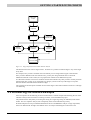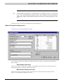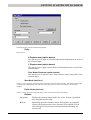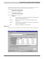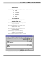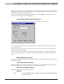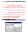
1
CRISP2D GEOTECHNICAL FINITE ELEMENT ANALYSIS SOFTWARE USER MANUAL For use with CRISP2D version 5 Prepared by The CRISP Consortium Limited www.mycrisp.com Copyright 2008 The CRISP Consortium Ltd, CRISP Geotech Inc. This manual may not be produced in whole or in part, by photocopy or print or any other means, without permission from either the CRISP Consortium Ltd or CRISP Geotech Inc. The CRISP Consortium Ltd is registered in England and Wales. Company No. 3222642. Address: 82 Stoke Fields, Guildford GU1 4LT, UK CRISP Geotech Inc is registered in the USA, Federal Tax No. 20-2780915. Address: 12739 Westella Dr, Houston, TX 77077, USA Contents Overview of CRISP2D 1.1 1.2 1.3 Program Capabilities Types of Analysis Interactive Graphical User Interface Dialogue-Based Data Entry Automatic Mesh Generation Constitutive Soil Models Finite Element Types Boundary Conditions On-Line Help Parametric Studies Post-Processing Printing Miscellaneous Program Limitations Program Structure Pre-Processor Finite Element Analysis Program Post-Processor Output Converter Report Generator CRISP2D Help Finite Element Analysis Help Guide To The Pre And Post Processor Menus 2.1 2.2 2.3 2.4 2.5 2.6 Introduction To The Pre-Processor Pre-Processor at Start-Up 2.2.1 Start-up Window 2.2.2 Menu bar at Start-Up 2.2.3 File menu at Start-Up 2.2.4 Help menu at Start-Up 2.2.5 Main toolbar at Start-Up Pre-Processor Mesh Modes Pre-Processor Options (Finite Element Mesh Mode) 2.4.1 Menu bar 2.4.2 File menu 2.4.3 Edit menu 2.4.4 Select menu 2.4.5 View menu 2.4.6 Mesh menu 2.4.7 Increment menu 2.4.8 Options menu 2.4.9 Help menu Pre-Processor Options (Unstructured Super Mesh Mode) 2.5.1 Menu Bar 2.5.2 Select menu 2.5.3 View menu 2.5.4 Mesh menu 2.5.5 Increment menu Pre-Processor Options (Structured Super Mesh Mode) 2.6.1 Menu bar 2.6.2 Mesh menu 1-1 1-1 1-1 1-1 1-1 1-1 1-1 1-1 1-2 1-2 1-2 1-2 1-2 1-2 1-2 1-3 1-3 1-3 1-4 1-4 1-4 1-4 1-4 2-1 2-1 2-1 2-1 2-2 2-2 2-3 2-4 2-4 2-4 2-4 2-5 2-7 2-8 2-9 2-12 2-13 2-15 2-15 2-16 2-16 2-16 2-16 2-17 2-18 2-18 2-18 2-19 2.7 2.8 2.9 2.10 2.11 2.6.3 Increment menu Toolbars 2.7.1 Main Toolbar 2.7.2 Status Bar Introduction To The Post-Processor Post-Processor at Start-Up 2.9.1 Menu bar 2.9.2 File menu 2.9.3 Main Toolbar Post-Processor Options 2.10.1 Menu bar 2.10.2 File menu 2.10.3 Edit menu 2.10.4 Select menu 2.10.5 View menu 2.10.6 Plots menu 2.10.7 Animation menu 2.10.8 Options menu 2.10.9 Window menu Toolbars 2.11.1 Main Toolbar GETTING STARTED WITH CRISP2D 3.1 3.2 3.3 3.4 3.5 3.6 3.7 Introduction 3.1.1 The Pre-Processor 3.1.2 The Post-Processor 3.1.3 The Graphics Window Principles Selection and Deselection of Objects Graphics Modes Selecting Close or Super-Imposed Objects Attributes Legend Pre-Processing 3.2.1 Basic Prerequisites for Running an Analysis Introducing the Worked Example Starting and Initialising a Project 3.4.1 Starting a New Project 3.4.2 Initialising A New Project Project Setup Project Information Creating A Finite Element mesh The Grid 3.5.1 Creating Nodes Creating Nodes Graphically Creating Nodes Using The Node List Creating Nodes Using The Tunnel Nodes Option 3.5.2 Creating Elements Defining Material Zones 3.6.1 What is a Material Zone? 3.6.2 Choosing a Soil Model 3.6.3 Defining a Material Zone Material Properties dialogue box Assigning Element Properties 3.7.1 Finite Element Types 3.7.2 Material Zones 3.7.3 Assigning Finite Element Types and Material Zones 2-19 2-19 2-20 2-22 2-22 2-23 2-23 2-24 2-24 2-25 2-25 2-26 2-28 2-28 2-28 2-28 2-29 2-30 2-30 2-30 2-30 3-1 3-2 3-2 3-3 3-4 3-4 3-5 3-5 3-6 3-8 3-10 3-10 3-10 3-11 3-12 3-12 3-13 3-13 3-17 3-18 3-18 3-20 3-20 3-20 3-22 3-23 3-24 3-24 3-24 3-24 3-25 3-28 3-28 3-29 3-29 3.8 3.9 3.10 3.11 3.12 3.13 3.14 Defining In Situ Conditions Setting Up In Situ Stresses The In Situ Stress Converter Defining Analysis Conditions 3.9.1 Increment Blocks 3.9.2 Setting Up Increment Blocks 3.9.3 Viewing Increment Blocks 3.9.4 Applying Boundary Conditions 3.9.5 Load Conventions Graphical Representation of Normal Edge Loads Graphical Representation of Shear Loads 3.9.6 Load Conventions in the Analysis Program 3.9.7 Applying Loads Node Loads Edge Loads 3.9.8 Creating Construction Sequences Viewing and Selecting Added/Removed Elements Constructing Elements Removing Elements Reinstating Elements Running The Finite Element Analysis 3.10.1 Launching An Analysis 3.10.2 Running The Finite Element Analysis Program Equilibrium Errors Error Messages 3.10.3 The Analysis Docking Module Post-Processing 3.11.1 Introduction to the Post-Processor 3.11.2 Starting the Post-Processor From the Pre-Processor From the Start Button Output Interpretation Tools 3.12.1 Instance Graphs 3.12.2 Duration Graphs 3.12.3 Bending Moment Graphs 3.12.5 Customising Graphs Customising Graph Labels Customising Graph Data Sets: 3.12.6 Using Graphs in Other Applications Exporting Graphs to File Copying Graphs to Clipboard 3.12.7 Tips on Working With Graphs Output Visualisation Tools 3.13.1 Contour Plots Setting Up a Contour Plot 3.13.2 Status Plots 3.13.3 Displacement Plots 3.13.4 Bending Moment Plots Printing 3.14.1 Print Setup 3.14.2 Page Setup 3.14.3 Printing the Graphics Window 3.14.4 Printing Graphs 3.14.5 Printing Data 3.14.6 The Report Generator. Menu bar File menu 3-30 3-31 3-34 3-35 3-35 3-36 3-40 3-41 3-45 3-45 3-46 3-47 3-47 3-47 3-48 3-50 3-50 3-50 3-51 3-51 3-52 3-53 3-55 3-55 3-56 3-56 3-61 3-61 3-61 3-61 3-61 3-61 3-62 3-65 3-68 3-71 3-72 3-75 3-77 3-77 3-78 3-78 3-78 3-79 3-79 3-84 3-86 3-88 3-91 3-92 3-92 3-94 3-94 3-95 3-99 3-100 3-100 3.15 3.16 Edit menu Insert menu Format menu Help menu Page Setup Format Cells Saving And Creating/Restoring Backups of Your Project 3.15.1 Saving 3.15.2 Autosave 3.15.3 Creating and Restoring Backups Exiting CRISP2D A GUIDE TO THE ADVANCED FEATURES OF CRISP2D 4.1 3-100 3-101 3-101 3-101 3-102 3-106 3-109 3-109 3-110 3-110 3-112 4-1 Automatic Mesh Generation 4.1.1 Introduction 4.1.2 Unstructured Mesh Generator Creating Unstructured Super Elements Super Node Gradings If the Unstructured Generator Will not Run 4.1.3 Structured Mesh Generation Creating Structured Super Elements Super Edge Gradings 4.2 Advanced Mesh Options 4.2.1 Curved Edges 4.2.2 Interface Elements Viewing Interface Elements Selecting Interface Elements Creating Interface Elements Deleting Interface Elements 4.2.3 Super-Imposed Elements 4.3 Layers 4.3.1 Viewing Layers 4.3.2 Assigning Elements to Layers 4.4 Advanced Run Options 4.4.1 Specifying Output 4.4.2 Batch Runs 4.4.3 Parent/Child Analyses 4.4.4 Stop-Restart Analyses 4.5 Swapping Material Properties 4.6 Customising CRISP2D 4.6.1 Material Properties Validator MATVALUE.NEW File Format Record 1 - Number Of Material Models Record 2 - Material Model Number Record 3 - Number of Material Properties Record 4 - Material Property Definition (Record 5) - Next Material Model 4.6.2 Base Units 4.6.3 Defaults 4.6.4 Colours 4.6.5 Line Styles 4-1 4-1 4-2 4-3 4-3 4-6 4-6 4-7 4-7 4-12 4-12 4-14 4-14 4-14 4-15 4-15 4-16 4-18 4-18 4-19 4-19 4-19 4-24 4-26 4-27 4-30 4-31 4-31 4-31 4-31 4-32 4-32 4-32 4-33 4-34 4-36 4-40 4-44 MESH GENERATOR ERROR MESSAGES 5-1 5.1 General Advice 5.1.1 Mesh Generator Restrictions 5.1.2 Unstructured Mesh Generation Errors 5-1 5-1 5-1 5.2 Index 5.1.3 Structured Mesh Generation Errors Error Messages 5-1 5-2 6-1 Overview of CRISP2D OVERVIEW OF CRISP2D 1.1 Program Capabilities The following is a short summary of the facilities available in CRISP2D: Types of Analysis Undrained, drained or fully coupled (Biot) consolidation analysis of two-dimensional plane strain or axisymmetric (with axisymmetric loading) solid bodies. The finite element analysis program can also be used for three-dimensional analyses, but (in this version of CRISP2D) only without the aid of the Windows interface. Interactive Graphical User Interface Point-and-click graphical creation of finite elements and super elements; point-and-click selection capability; click-and-drag move feature. Graphical display of loads fixities and construction sequences. Full range of zoom and colour functions controlling the scope and appearance of the display. Dialogue-Based Data Entry All analysis data is entered via instructive and intuitive dialogue boxes, employing generic Windows artefacts. Data can be viewed and edited at any time simply by re-displaying the dialogue box. Automatic Mesh Generation Automatic generation of a finite element mesh from a super mesh, using either unstructured or structured mesh generation techniques. Constitutive Soil Models Homogeneous linear elastic, homogeneous anisotropic linear elastic, non-homogeneous isotropic linear elastic (properties varying with depth), linear elastic-perfectly plastic (with Von Mises, Tresca, Drucker-Prager or Mohr-Coulomb yield criteria), critical state based models - Cam clay, modified Cam clay, and Schofield soil. In addition, version 5 also has the following soil models: non-associated Mohr-Coulomb (new Mohr Coulomb) and advanced Mohr-Coulomb elastic-plastic hardening, Duncan & Chang hyperbolic model, the Three Surface Kinematic Hardening critical state soil, new Small Strain stiffness model (Gunn1), and new Rotational Hardening Cam Clay model (S-Clay) Finite Element Types Linear strain triangle, cubic strain triangle, linear strain quadrilateral and (for 3D analysis only) the linear strain brick element - all with additional excess pore pressure degrees of freedom (for 1-1 Overview of CRISP2D consolidation analysis). Beam, bar, interface elements without pore pressure nodes and interface elements with pore pressure nodes along one side (for two-dimensional plane strain analysis only). Boundary Conditions Prescribed incremental displacements or excess pore pressures on element edges. Nodal loads or pressure (normal and shear) loading on element edges. Automatic calculation of loads simulating excavation or construction when elements are removed or added. On-Line Help A comprehensive system of context-sensitive on-line help describing the features within the interface that can be accessed directly from within data entry dialogue boxes. Context-sensitive help describing error messages issued by the analysis program. Parametric Studies Ability to compare results across separate but related analyses. Parametric studies can be run to compare the effect of changing applied loads, displacement fixities, pore pressure fixities, sequence of construction, number of increments and load or time step sizes. Post-Processing Graphs, contour plots, displacement plots, vector plots, bending moment plots and stress state plots; all viewable on an interactive graphical display of the finite element mesh. Printing Printed copy of the graphical display in ‘What-You-See-Is-What-You-Get’ (WYSIWYG) mode. Formattable printed copy of input and output data, including a Template feature to record preferred formats. Miscellaneous Stop-restart facility to permit continuation from a previous run. Output restriction options permitting only selected increments of an analysis to be written to disk for post-processing. 1.2 Program Limitations CRISP2D is a finite element program, which is able to perform drained undrained and time dependent analysis of static problems (not dynamic) under monotonic loading/unloading conditions. It is not suitable for stress cycling in its present form, nor is it capable of handling partially saturated conditions. CRISP2D also has a large deformation option, using the updated Lagrangian method. This is only suitable for use with elastic and elastic-perfectly plastic soil models – not critical state. Plane strain and axisymmetric analysis can be carried out using the Windows interface. Axisymmetric analyses are limited to loading that is also axisymmetric, hence torsion loading cannot be modelled using the axisymmetric option. The analysis program can run three-dimensional analyses, but the Windows interface cannot then be used. For example, CRISP2D in its present form could not be used to model the driving of a pile, as this is a dynamic event. However, it could model the behaviour of a pile that was already installed. Furthermore, axisymmetric analysis could be used if the pile loading was purely axial, otherwise full 3D would be required. 1-2 Overview of CRISP2D It is entirely your responsibility to decide whether or not the models available in CRISP2D are adequate to represent the soil behaviour encountered in a real field situation. Some known deficiencies of the available models are as follows: Small-strain behaviour may not be adequately modelled in most of the availabe models. Very large stiffnesses are reported (Jardine et al, 1984; Powrie, 1986) at small strain levels and also at load reversal. For problems that require the modelling of small-strain stiffness effects, the 3 surface kinematic harening (3SKH) model should be used. The constitutive models currently available in CRISP2D are not suitable for the analysis of partially saturated soils. 1.3 Program Structure The CRISP2D suite of programs is made up of the following components: Pre-Processor Finite Element Analysis Program Post-Processor Output Converter Report Generator CRISP2D Help Finite Element Analysis Help Pre-Processor The Pre-Processor is used to generate input data for the Analysis Program. It allows you to graphically create a finite element mesh, to define soil properties, to specify in situ conditions, to define increment blocks, to apply loads and fixities, to simulate construction sequences and to set run options for the Analysis Program. It also allows you to view, manipulate and print the mesh and all associated input data. Finite Element Analysis Program The finite element analysis engine comprises two separate programs: the ‘Geometry Program’ and the ‘Main Program’. Essentially, the Geometry Program deals with mesh processing and checking whilst the Main Program solves the finite element equations. In addition, there are double precision versions 1-3 Overview of CRISP2D of both programs. The Analysis Program provides visual prompts (text messages) as to the progress of the analysis. It is not, however, interactive and once set in motion will run until it is halted or the analysis is complete. Post-Processor The Post-Processor is used to look at the results output by the Analysis Program. Post-processing features include a comprehensive graphing module, displacement plots, contour plots, bending moment plots, status plots and stress state plots. It also allows you to view and print the mesh and all associated input and output data. Output Converter Results from the Main Program are written to files on disk. The Output Converter takes raw data from these files and converts it into a Microsoft Access 2.0 database, from which all post-processing output is drawn. Report Generator The Report Generator provides a customisable environment in which printed copy of input and output data can be formatted. CRISP2D Help A standard Windows Help file containing a comprehensive guide to both the Pre- and Post-Processor Windows interfaces. Finite Element Analysis Help A standard Windows Help file containing a listing and description of all error messages that may be output by the Analysis Program. 1-4 Guide To The Pre And Post Processor Menus GUIDE TO THE PRE AND POST PROCESSOR MENUS 2.1 Introduction To The Pre-Processor The Pre-Processor allows you to set-up and run a Finite Element Analysis from scratch. A finite element mesh can be created graphically and analysis conditions can be imposed onto this mesh. Analysis conditions include the setting up of soil zones with a choice of soil models, specification of material properties, defining a stress history for the soil and the application of construction sequences, boundary conditions and loading conditions to the mesh. 2.2 Pre-Processor at Start-Up On starting up CRISP2D you have restricted access to the program’s facilities. Access to all the features of CRISP2D is possible only after you have opened a Project: either a new Project or a previously saved Project. 2.2.1 Start-up Window On first entering the CRISP2D Pre-Processor, you see the Start-up window: 2-1 Guide To The Pre And Post Processor Menus The Start-up window consists of the following main areas: Start-up menu bar which gives you access to the Start-up menus Start-up toolbar which gives you access to the Post-Processor 2.2.2 Menu bar at Start-Up On starting up the CRISP2D Pre-Processor, you have the following menus available from the Start-up menu bar. File menu The File menu controls the opening and closing of a Project. Help menu The Help menu controls access to the CRISP2D on-line help system. 2.2.3 File menu at Start-Up 2-2 Guide To The Pre And Post Processor Menus The File menu options available to you at start-up are: New Project... (menu item) See Section2.3 for further details about mesh modes Creates a new Project. This clears out any existing Project information and initialises CRISP2D ready for new data. The Select Mesh Mode dialogue box is then displayed, allowing you to choose which mode you wish to work in. Open Project... (menu item) Opens a previously-saved Project. Previously-saved Projects have the file extension .SCD. You must specify the Project file name, which can be selected from any valid drive or directory. Import CRISP94 Mesh... (menu item) Opens a Project using geometry data created by the previous version of CRISP, CRISP94. The file containing the geometry data will have a .GPD extension. Import CRISP94 Analysis... (menu item) Starts up a Project using geometry data, increment block data and material properties data created by CRISP94. This option requires files with the extension .GPD and .MPD, both with the same name and in the same directory. Print Setup... (menu item) Displays the standard Windows Print Setup dialogue box. Exit (menu item) Exits you from CRISP2D. Recently opened file list (menu item) Allows the user to open one of the four most recently opened projects by selecting them from the list. 2.2.4 Help menu at Start-Up The Help menu options available to you at Start-up are: Contents... (menu item) Displays the Contents page of the CRISP2D on-line help system. Index... (menu item) Displays the Index page of the CRISP2D on-line help system. Search... (menu item) Displays the Search page of the CRISP2D on-line help system. About... (menu item) Displays the About... box which gives details about the version of CRISP2D you are running and allows you to check the available Windows system resources. Clicking the OK button exits the About box. 2-3 Guide To The Pre And Post Processor Menus 2.2.5 Main toolbar at Start-Up The options available to you from the CRISP2D Pre-Processor start-up toolbar are as follows: New Project (button) Open Project (button) Load Post-Processor (button) Help (button) 2.3 Pre-Processor Mesh Modes There are differences in the CRISP2D interface when you are starting a new Project depending on whether you have opted to work on an Unstructured or Structured Super Element Mesh or on a Finite Element Mesh. These differences are apparent in the menu options available to you from the menu bar. The menus and options available in Finite Element Mesh mode are documented here. The menus and options available for Unstructured Super Mesh mode are documented in here, and here for Structured Super Mesh mode. These are largely identical to the Finite Element options, so only the differences are described. If you open an existing Project the mesh mode and associated available options will be the same as when the Project was saved. 2.4 Pre-Processor Options (Finite Element Mesh Mode) 2.4.1 Menu bar On opening a new Project in the CRISP2D Pre-Processor, if you are working in Finite Element Mesh mode you have the following menu options available on the menu bar: File menu The File menu controls the opening and closing of a Project. Edit menu The Edit menu allows access to the Undo last action feature, the saving and restoring of backups of your Project (Bookmarks) and to the Attributes information box. Select menu The Select menu allows you to select any object in the Graphics Window, such as nodes, elements or edges. The selected object will be highlighted. 2-4 Guide To The Pre And Post Processor Menus View menu The View menu controls all aspects of what you can see on the screen. This includes toggles that control the display of nodes, fixity icons, element numbers etc. You can also access the Zoom features to view different parts of your mesh more easily. Mesh menu The Mesh menu allows you to create and move nodes and elements, create curved edges, assign element and material properties and super-impose elements. Increment menu The Increment menu allows you to define in situ stress conditions and increment blocks. You can also add or remove elements and apply fixities and loads to the current increment block. Options menu The Options menu allows you to set the applications defaults, such as the base unit system, colour defaults and grid details. Help menu The Help menu controls access to the CRISP2D on-line help system. 2.4.2 File menu The File menu options available to you from within the CRISP2D Pre-Processor are: New Project... (menu item) Same as menu item in the start-up File menu. Open Project... (menu item) Same as menu item in the start-up File menu. Close Project (menu item) If you have made changes to your Project, you are first prompted to save these changes. The Project is then closed. Save Project (menu item) Allows you to save your Project overwriting any previously saved file. Save As... (menu item) Allows you to save your Project under a different Project name. You must enter a file name. You can save the file in a different directory/drive. Load Super Mesh... (menu item) Allows you to extract super mesh data from another (existing) Project. If you have a Project open already you are first prompted to save this Project. You must then enter the path and file name of the Super Mesh Project you want to open. Load Finite Element Mesh... (menu item) Allows you to extract finite element mesh data from another (existing) Project. Only information about the geometry of the Finite Element mesh will be loaded from the opened Project. 2-5 Guide To The Pre And Post Processor Menus If you have a Project open already, you are first prompted to save this Project. You must then enter the path and file name of the Finite Element Mesh Project you want to open. Clicking Cancel closes the dialogue box and the current Project remains displayed. Import CRISP94 Mesh... (menu item) Same as menu item in the start-up File menu. Import CRISP94 Analysis... (menu item) Same as menu item in the start-up File menu. Project Setup… (menu item) Displays the Project Setup dialogue box. Project Information... (menu item) Displays the Project Information dialogue box. This allows you to enter identifying information for the Project you are working on. Print Setup… (menu item) Displays the Print Setup dialogue box. Print Graphics (menu item) Prints the contents of the Graphics Window to the default printer. Print Data... (menu item) Displays the Print Selection (Data) dialogue box. This allows you to select what data to include in a printed report of your Project, and leads on to the CRISP2D Report Generator inside which you can format and apply templates to your selected data. Export Screen to Metafile... (menu item) This allows you to export the contents of the Graphics Window to disk in the standard Windows metafile (WMF) file format. Parent/Child... (menu item) Displays the Parent And Children dialogue box. This allows you to set up Parent and Child relationships between Projects in order to run a series of comparative analyses. Setup Batch Run... (menu item) Displays the Batch Run dialogue box. This allows you to create a batch file containing one or more analyses to run. These will then be submitted to CRISP to run consecutively when Run Analysis is selected. Run Analysis... (menu item) This will automatically validate the data that has been entered, create the files required to run the finite element program, run the analysis and load the results into the Post-Processor (via the Analysis Launcher and Docker modules). Compact File (menu item) This operates on the current project. The data file (*.scd) is compacted by renumbering edges, elements and nodes so that there are no gaps in the numbering. It can solve some problems caused by deletions. 2-6 Guide To The Pre And Post Processor Menus Exit (menu item) Exits you from CRISP2D. You are prompted to save any changes you have made to your Project. Recently opened file list (menu item) Allows the user to open one of the four most recently opened projects by selecting them from the list. 2.4.3 Edit menu The Edit menu options available to you from within the CRISP2D Pre-Processor are: Undo action mode (menu item) The action modes that may be undone are Create Element Move Node Undoing element creation will cause all new nodes and elements that you have created since entering Create Element mode, or since you last clicked on Commit Elements, to be erased. Undoing a move will reverse the move that you are currently making. Commit Element Creation (menu item) This option is greyed out if you are not in Create Element mode. This will commit all new nodes and elements created since you entered Create Element mode, or since you last clicked on Commit Elements. Until nodes and elements are committed they cannot be selected and (nodes) will not appear in the Node List. Note that all new nodes and elements are automatically committed when you change action mode (e.g. by changing to Select Node mode). Save As Bookmark... (menu item) Displays the Save Bookmark dialogue box. This allows you store a backup copy of your Project (a bookmark) to which you may return if you wish to undo all changes made from there onwards. Load Bookmark... (menu option) Displays the Load Bookmark dialogue box. This allows you to restore a backup version (i.e. a saved bookmark) of your Project. Align Nodes (sub-menu heading) If no nodes are selected, this option is greyed out. When one or more nodes are selected, the options become available. Vertically (sub-menu item) Allows you to align the selected nodes in a vertical column. Horizontally (sub-menu item) Allows you to align the selected nodes in a horizontal row. 2-7 Guide To The Pre And Post Processor Menus Delete (menu item) If no elements, nodes or edges are selected, these options are greyed out. The options become available when one or more objects in the graphics window are selected. Selection (sub-menu item) All currently highlighted items will be deleted. You will be prompted for confirmation of any deletion. Unattached Nodes (sub-menu item) All nodes, which are not attached to elements at any time through out the analysis, will be deleted. Attributes... (menu item) Displays a dialogue box that informs you of the current status of all attributes belonging to the currently selected objects (node, edge, element, etc.). If nothing is selected then the Attributes dialogue box will display “Nothing selected”. Find... (menu item) Displays a dialogue box that offers you the choice of searching for a node, element or edge by it’s number. 2.4.4 Select menu The Select menu options allow you to select specific types of object that are displayed in the Graphics Window by left clicking on or near that object. The currently actioned Select mode is indicated by a tick to the left of one of the items in the menu. Selectable objects are: Nodes (menu item) Edges (menu item) Domain Elements (menu item) Line Elements (menu item) In conjunction with the above selection options, you can use the following menu options: Select All (menu item) Selects everything in the Graphics Window of the current selection type. Order Selection (menu item) Orders the current selection of nodes in ascending x, y or numeric order Define Group Select (menu item) This allows you to draw a box in the Graphics Window to select all items indicated by the current selection mode. Note that only items fully enclosed by the box will be selected. First select the item by clicking on it in the select menu. Then draw the box by clicking with the left mouse button and moving the cursor. Select Group (menu item) Click this to select the items you have enclosed. They will appear highlighted on the screen. 2-8 Guide To The Pre And Post Processor Menus De-select Group (menu item) Whereas Clear Selection will clear all the selected items you can use this function to clear a selected amount. First define the group to be de-selected by using the Define Group Select command. Next click on De-select Group to clear them. Clear Selection (menu item) All item(s) currently selected are de-selected. 2.4.5 View menu The View menu controls what you see in the Graphics Window at any time. Each item in the menu that is ticked is visible; each item not ticked is invisible. By clicking on the different menu items you can toggle the display of that object in the Graphics Window. For instance, to display all nodes on the screen, Nodes must be ticked. If Nodes is not ticked, no nodes will be visible in the Graphics Window. Viewing of the following objects is controlled via the View menu: Nodes (menu item) Allows you to toggle the display of all nodes. Nodes are displayed in the Graphics Window as small X’s. Node Numbers (menu item) Allows you to toggle the display of all node numbers. With the Node Numbers toggle on, node numbers appear close to the node that they are referencing. Domain Elements (menu item) Allows you to toggle the display of all domain finite elements. Domain elements are displayed as polygons without any fill. Line Elements (menu item) Allows you to toggle the display of all line (1D) finite elements. In order to differentiate between domain element edges and line elements, line elements are displayed in a different colour to domain element edges. Tip Line elements can be most easily seen with View Domain Elements toggled off. Element Numbers (menu item) Allows you to toggle the display of all element numbers. With the Element Numbers toggle on, element numbers appear at the centroid of the element that they are referencing. Material Zones (menu item) Allows you to toggle the display of all material zones. 2-9 Guide To The Pre And Post Processor Menus Material Zones are displayed as a fill colour inside domain elements that have been assigned to the zone. Element Types (menu item) Allows you to toggle the display of finite element type information. Each of the 14 different finite element types is indicated by a fill colour inside domain elements, or by a line colour for line elements. Fixities (menu item) Allows you to toggle the display of all fixity icons. Fixities are represented by fixity icons that appear attached to the nodes and edges that have been fixed. Loads (menu item) Allows you to toggle the display of load icons. Loads are represented by icons that appear floating close to the nodes and edges to which loads have been applied. Legend (menu item) Allows you to control whether or not a legend is displayed or printed. Outline (menu item) Allows you to view only edges which are at an external border or between two different soil zones. Absolute (menu item) Allows you to view all applied loads and fixities from any earlier increment block in the analysis. It should be used in conjunction with Fixities and Loads. Tip Change the colours of absolute fixities and loads in the Options, Colour dialog box, to distinguish them from loads/fixities applied in the current increment block. Layers (menu item) Opens a dialogue box which allows layers to be added, deleted or switched on and off. Present Elements (menu item) Used in conjunction with Removed Elements, this allows you to view which elements are present in the current increment block so that you can view the current stage of a construction sequences. This is the default view. Removed Elements (menu item) Used in conjunction with Present Elements, this allows you to view which elements are not present in the current increment block so that you can select elements to add to a construction sequence. 2-10 Guide To The Pre And Post Processor Menus Slip Element Offset (menu item) Allows you to toggle on and off the offsetting of slip elements from their original positions. The offset feature is included to help clarify the positioning of slip elements in relation to their neighbouring domain elements. Current Nodes Only (menu item) Controls whether or not nodes belonging to elements in the ‘removed’ state are displayed when the viewing of nodes is toggled on. Zoom (sub-menu heading) The Zoom options allow you to view your mesh at different magnification values. These options are also available from a combo box on the main toolbar. All zooms are activated by clicking in the Graphics Window with the right mouse button. The options available are: No Zoom (sub-menu item) De-activates the right mouse button so that no zoom takes place when it is clicked. Zoom In (sub-menu item) Increases the magnification by the default Zoom Increment each time you click on your right mouse button. The default Zoom Increment can be altered via the Default Settings dialogue box (in the Options menu). Zoom Out (sub-menu item) Reduces the magnification by the default Zoom Increment each time you click on your right mouse button. The default Zoom Increment can be altered via the Default Settings dialogue box (in the Options menu). Zoom Previous (sub-menu item) Restores the previous zoom setting. This allows you to traverse backwards through all of the 20 most recent zoom settings. Zoom Next (sub-menu item) If a Zoom Previous has been actioned, this allows you to traverse in the other direction, i.e. forwards towards the zoom setting that was in force when you first actioned a Zoom Previous. Zoom Window (sub-menu item) The zoom window is drawn by holding down the right mouse button and moving the cursor. This will display a box that sizes itself to the position of your cursor. The screen will zoom to the selected area on release of the right button. 2-11 Guide To The Pre And Post Processor Menus Tip The zoom window can be moved around the screen by pressing the CTRL key whilst still having the right mouse button held down. Any mouse movements now will cause the displayed box to move around the screen without its resizing. This allows you to home in on exactly where you want the zoom window to be centred. Full Page (sub-menu item) This scales the Graphics Window so that it displays all objects on the screen. Pan (sub-menu item) Allows you to move around your mesh without changing scale. To pan around the mesh, move the mouse cursor to the point that you wish to move to the centre of the Graphics Window and click the right mouse button. Zoom Centre (sub-menu item) Allows you to automaticaly move the centre of the mesh to the centre of the screen without changing scale. Super Mesh (menu item) This allows you to switch to Super Mesh mode. If you have previously selected either Unstructured or Structured Super Mesh mode, clicking this will make the finite element mesh invisible and display the super mesh. This option will be greyed out in a child analysis or if the finite element mesh was created manually. 2.4.6 Mesh menu This menu controls the creation and manipulation of all geometric aspects of building a finite element mesh. The Mesh menu options available to you in Finite Element mesh mode are: Node List... (menu item) Displays the Node List dialogue box This allows you to create new finite element nodes and to edit the positions of existing nodes by entering co-ordinates directly from the keyboard. Create Elements (menu item) Allows you to create finite elements by drawing them directly onto the Graphics Window. A tick will be displayed next to the menu item if you are in Create Element mode. Create Slip Element (menu item) Creates a chain of slip (interface) elements around the selected elements in the Graphics Window. 2-12 Guide To The Pre And Post Processor Menus Move Node (menu item) Allows you to move selected nodes in the Graphics Window. Tunnel Nodes (menu item) Displays the Tunnel Nodes Setup dialogue box. This allows you to automatically create nodes in a circular pattern a specified radius from a particular centre point. Merge Nodes (menu item) This allows selected nodes to be combined into a single node. Curved Edge... (menu item) Displays the Curved Edge Specification dialogue box. This allows you to change a straight edge into a curved one based on a specified radius of curvature. Element Properties... (menu item) Displays the Element Properties dialogue box. This allows you to assign a Material Zone and a Finite Element type to the current selection of elements. Material Properties... (menu item) Displays the Material Properties dialogue box This allows you to create and edit Material Zones. Super-Impose Elements... (menu item) Displays the Super-Imposed Layer dialogue box: See Section 3 in the Technical Reference Guide further information about super-imposing elements The Super-Imposed Layer dialogue box allows you to create a new layer of elements on top of a selection of existing elements. This new layer can then be geometrically manipulated within the region enclosed by the originally selected elements. 2.4.7 Increment menu This menu controls the specification of parameters required to formulate analysis data for the finite element program. This includes in situ stress conditions, increment block definition, application of loads and fixities and the simulation of construction sequences. The Increment menu options available to you from within the CRISP2D Pre-Processor are: Define In-Situ Stress Conditions... (menu item) Displays the In Situ Stress Setup dialogue box. This allows you to define in situ stress conditions for your mesh. Define Increment Block Parameters... (menu item) Displays the Increment Block Information dialogue box. This allows you to set up increment blocks for your analysis. 2-13 Guide To The Pre And Post Processor Menus Output (menu item) This allows you to conserve hard disk space by restricting the volume of data output by the analysis program. Specify... (sub-menu item) Displays the Output Options dialogue box. This allows you to restrict the output for each increment. Restrict... (sub-menu item) Displays the Restrict Options dialogue box. This allows you to restrict output for a selection of elements. Fixities... (menu item) Allows you to apply fixities to selected nodes and edges. The dialogue box that is displayed will depend upon whether you have selected nodes or edges. If a node or group of nodes is selected, the Node Fixity dialogue box will be displayed. This allows you to apply fixities to each selected node. If an edge or group of edges is selected, the Edge Fixity dialogue box will be displayed. This allows you to apply fixities to each of the selected edges. Loads... (menu item) Allows you to apply loads to selected nodes and edges. The dialogue box that is displayed will depend on whether you have selected nodes or edges. If a node or group of nodes is selected, the Node Load dialogue box will be displayed. This allows you to apply a point load to each selected node. If an edge or group of edges is selected, the Edge Load dialogue box will be displayed. This allows you to apply pressure loadings to each of the selected edges. Remove Elements (menu item) This allows selected elements to be removed during the current increment block. This option is greyed out if you are currently viewing removed elements. Provided at least one element has been selected in the Graphics Window, clicking on Remove Element will remove the element from the current increment block. The elements will stay removed in all successive increment blocks until they are added back using Add Element. Add Elements (menu item) This allows previously removed elements to be added to the current increment block. This option is greyed out if you are currently viewing added elements. Provided at least one of these removed elements has been selected in the Graphics Window, clicking on Add Element will add the elements to the current increment block. The elements will remain added in all successive increment blocks, unless they are removed again using Remove Element. Select Restart Increments... (menu item) Displays the Stop/Restart dialogue box. This allows you to set up an analysis which will be split up into a number of shorter analyses. 2-14 Guide To The Pre And Post Processor Menus 2.4.8 Options menu The Options menu choices available to you from within the CRISP2D Pre-Processor are: Default Settings... (menu item) Displays the Defaults dialogue box. This allows you to specify default settings for the following processes: Load/Save Zoom General Scale Factors Colour... (menu item) Displays the Colour Selection dialogue box. This allows you to customise the colours in which different objects are displayed on the Graphics Window. Line Styles... (menu item) Displays the Line Styles dialogue box. This allows you to change the line style for the edges of elements and for ancillary lines that do not form part of any element. Printer Legend Font… (menu item) Displays the Font dialogue box Grid... (menu item) Displays the Grid Options dialogue box. This allows you set up a regular background grid that can be used to assist with all drawing actions in the Graphics Window. When you left click on the Graphics Window with the SHIFT key held down, you will automatically snap to the closest grid point. Units... (menu item) Displays the Units dialogue box. This allows you to change the default system of base units that is be used for your Project. 2.4.9 Help menu Refer here for details. 2-15 Guide To The Pre And Post Processor Menus 2.5 Pre-Processor Options (Unstructured Super Mesh Mode) 2.5.1 Menu Bar See Section 2.4.1 for information about options not described here. Whilst working on a Project in Unstructured Super Mesh mode, the menu options available from the menu bar are largely the same as in Finite Element mode. Only those options that are either modified or additional to the Finite Element options are described here. The only differences are in the View, Select and Mesh menus. No increment options are available at the super mesh stage, so the Increment menu does not appear. The menus available from the menu bar are: File menu Edit menu Select menu View menu Mesh menu Increment menu Options menu Help menu 2.5.2 Select menu The Select menu options available to you in Unstructured Super Mesh mode are identical to the options in Finite Element Mesh mode except that nodes, edges and elements are termed Super Nodes, Super Edges and Super Elements. 2.5.3 View menu The View menu options available to you in Unstructured Super Mesh mode are largely identical to the options in Finite Element Mesh mode except that nodes, edges and elements are termed Super Nodes, Super Edges and Super Elements. Altered functionality is as follows: 2-16 Guide To The Pre And Post Processor Menus Loads (menu item) All increment options are unavailable, so this option is not displayed. Fixities (menu item) All increment options are unavailable, so this option is not displayed. Present Elements (menu item) Elements cannot be added or removed in Super Mesh mode, so this option is not displayed. Removed Elements (menu item) Elements cannot be added or removed in Super Mesh mode, so this option is not displayed. Current Nodes Only (menu item) Super Elements cannot be be added or removed, so this option is not applicable. Finite Element Mesh (menu item) Allows you to switch from Unstructured Super Mesh mode to Finite Element Mesh mode. This will display your Finite Element mesh (if any exists) and give you access to all the Finite Element Mesh mode menu options. Your Super mesh will be left unchanged from the time that you enter Finite Element Mesh mode to the time that you return to your Super mesh. Similarly, no changes will be made to your Finite Element mesh throughout the time that you are either in Super Mesh mode. However, if you change to Finite Element Mesh mode by generating a mesh, any existing Finite Element mesh information will be lost. 2.5.4 Mesh menu This menu allows you to create, edit and assign properties to an unstructured super mesh. Super Node List... (menu item) Displays the Super Node List dialogue box. This allows you to view and edit a table containing numbers, co-ordinates and nodal gradings of all super nodes in the Project. Create Super Element (menu item) Allows you to create unstructured super elements in the Graphics Window. Move Super Node (menu item) Allows you to move selected super nodes in the Graphics Window. Tunnel Nodes (menu item) Displays the Tunnel Nodes Setup dialogue box. This allows you to automatically create nodes in a circular pattern a specified radius from a particular centre point. Merge Nodes (menu item) This allows selected super nodes to be combined into a single node. Curved Super Edge... (menu item) Displays the Curved Edge Specification dialogue box. 2-17 Guide To The Pre And Post Processor Menus This allows you to change a straight edge into a curved one based on a specified radius of curvature. Super-Impose Super Elements... (menu item) Displays the Super-Imposed Layer dialogue box: Super Node Grading... (menu item) Displays the Super Node Grading dialogue box. This allows you to assign a grading value to each selected super node. Generate Finite Element Mesh (menu item) Generates the finite element mesh from the super mesh 2.5.5 Increment menu No increment options are available in super mesh mode, so all are greyed out. 2.6 Pre-Processor Options (Structured Super Mesh Mode) 2.6.1 Menu bar See Section 2.4.1 for information about options not described here. Whilst working on a Project in Structured Super Mesh mode, the menu options available from the menu bar are largely the same as in Finite Element mode or in Unstructured Super Mesh mode. Only the additional or modified options are documented here. The menus available from the menu bar are: File menu Edit menu Select menu View menu Mesh menu Increment menu Options menu Help menu 2-18 Guide To The Pre And Post Processor Menus 2.6.2 Mesh menu This menu allows you to create, edit and assign properties to an structured super mesh. Super Node List... (menu item) Displays the Super Node List dialogue box. This is identical in operation and appearance to the Node List in finite element mode, except that it refers to the numbers and co-ordinates of super nodes instead of finite element nodes. Create Super Element (menu item) Allows you to create structured super elements in the Graphics Window. Move Super Node (menu item) Allows you to move selected nodes in the Graphics Window. Tunnel Nodes (menu item) Displays the Tunnel Nodes Setup dialogue box. This allows you to automatically create nodes in a circular pattern a specified radius from a particular centre point. Merge Nodes (menu item) This allows super nodes to be combined into a single node. Curved Super Edge... (menu item) Displays the Curved Edge Specification dialogue box. This allows you to change a straight edge into a curved one based on a specified radius of curvature. Super-Impose Super Elements... (menu item) Displays the Super-Imposed Layer dialogue box: Super Edge Gradings... (menu item) Allows you to assign grading functions to each selected super edge. If a single super edge is selected, the Super Edge Grading dialogue box will be displayed. If more than one edge is selected, the Multiple Super Edge gradings dialogue box is displayed. This allows you to assign edge gradings either by weighting function, or by entry of the co-ordinates for each division along the edge (the latter is for singular edge selections only). Generate Finite Element Mesh (menu item) Generates the finite element mesh from the super mesh 2.6.3 Increment menu No increment options are available in super mesh mode, so all are greyed out. 2.7 Toolbars Toolbars are used in CRISP2D to provide fast access to operations also available via the menus. 2-19 Guide To The Pre And Post Processor Menus There is also a status bar across the bottom of the main screen that displays information about your current working status. The following Toolbars are available: Main Toolbar Status Bar 2.7.1 Main Toolbar The main toolbar extends horizontally across the screen, directly beneath the menu. The mesh mode in which you are working affects the buttons that appear in the main toolbar. In Finite Element mode, the features available via the toolbar are as follows: New Project (button) Open Project (button) Close Project (button) Save Project (button) Zoom (list box) Node List (button) Grid (button) Increment Block (list box) or Toggle display of current/removed elements (button) Load Post Processor (button) Layers (button) Help (button) The list boxes each provide access to an additional set of features: Zoom (list box) The zoom options in the list box provide identical functionality to the zoom options available via the View menu (see here for details). The zoom mode displayed is activated by clicking the right mouse button. 2-20 Guide To The Pre And Post Processor Menus The options available are: No Zoom Zoom In Zoom Out Zoom Previous Zoom Next Zoom Window Pan Full Page Zoom Centre Increment Block (list box) Lists all the increment blocks in your analysis by name. The current increment block is the block that is selected in the list. The list provides a very easy way of changing between increment blocks. When an increment block is selected, the Graphics Window displays the mesh as an up-to-date picture of how the analysis will appear during that increment block. This means that any elements not present (i.e. removed) will not be displayed; fixity icons will appear where nodes and edges are fixed and load icons will appear where loads are currently being applied. Any elements that you add or remove, and any loads or fixities applied, will be stored as the set of analysis conditions. These will be applied during the course of the current increment block in the finite element analysis program. Tip With the cursor in the list box, press the up and down cursor keys to change between increment blocks. Every time you press a key, the loads, fixities and mesh geometry will be updated providing a basic slide show. This is a useful way of visualising the progression of the analysis, especially when you are modelling a long or complicated series of events. 2-21 Guide To The Pre And Post Processor Menus Load Post Processor (button) Opens the Post-Processor and loads the current file Note This button only loads the Post-Processor and does not run the analysis. Any alterations made to the file in the pre processor will only effect the results if the analysis has been run using Run Analysis in the File menu. Layers (button) Opens the Layers dialog box, enabling you to create, edit or delete layers. 2.7.2 Status Bar The Status Bar at the bottom of the window displays the following information: Description of any processing operation that is taking place, e.g. Importing Geometry Data. Percentage fill bar showing how much of the processing operation has been completed. Displays the current action mode, e.g. ‘SELECT EDGE’. On start-up, this field is blank. Date and time. GRID box. The text is black if the grid is currently displayed, otherwise it is grey. The Grid Options dialogue box may be loaded by double clicking on the GRID box. Cursor co-ordinates (measured in the current length units). The coordinates displayed relate directly to the co-ordinates of points within the mesh. 2.8 Introduction To The Post-Processor The Post-Processor includes a set of utilities that allow you to look at output from your analysis in a number of different ways. You can view output data as it changes from increment to increment, or plot variations across the mesh. You can also compare output from separate (parent/child) analyses. Contour plots, status plots and displacement plots allow you to look at the overall picture of what has happened to the mesh throughout the course of the analysis. 2-22 Guide To The Pre And Post Processor Menus If you have run an analysis from the Pre-Processor, the Analysis Docker will present you with the option of entering the Post-Processor to view your results directly. Alternatively, the Post-Processor can be run as a stand-alone application which can load in results from a previously completed analysis. The following sections describe the options available to you from within the CRISP2D Post-Processor. 2.9 Post-Processor at Start-Up The features that are accessible to you when you start the Post-Processor as a standalone application are as follows: Menu bar File menu Edit menu Select menu View menu Plots menu Options menu Window menu Main toolbar 2.9.1 Menu bar The CRISP2D Post-Processor provides you with the following menu options available on the menu bar at start-up: File menu The File menu controls the opening and closing of a Project and set-up for printing. Edit menu No options are available until a project has been opened. Select menu No options are available until a project has been opened. 2-23 Guide To The Pre And Post Processor Menus View menu No options are available until a project has been opened. Plots menu No options are available until a project has been opened. Animation menu No options are available until a project has been opened. Options menu No options are available until a project has been opened. Window menu No options are available until a project has been opened. Help menu The Help menu controls access to the CRISP2D on-line help system. 2.9.2 File menu The file menu allows access to Projects created by the CRISP2D Pre-Processor. Open Project... (menu item) Allows you to open a Project created by the Pre-Processor to carry out post-processing operations on the Finite Element Analysis output. If a saved Project is opened here without having first run the Finite Element Analysis program, an error message is issued since no output data exists. Page Setup... (menu item) Displays the Page Setup dialogue box. This allows you to change the way that graphs and the Graphics Window appear on the printed page. Print Setup... (menu item) Displays the standard Windows Print Setup dialogue box. Exit (menu item) Exits you from CRISP2D. Recently opened file list (menu item) Allows the user to open one of the four most recently opened projects by selecting them from the list. 2.9.3 Main Toolbar The features available via the toolbar are as follows: Open Project (button) Load Pre-Processor (button) 2-24 Guide To The Pre And Post Processor Menus Help (button) 2.10 Post-Processor Options Once you have opened a Project, then provided that the Project has a database attached (i.e. that the Finite element analysis has been successfully run) you have access to all of the features in the CRISP2D PostProcessor. A number of features are shared by both the Pre- and Post-Processors. The main differences between them are: No changes may be made to mesh geometry or to increment block information, and Six visualisation and interpretation tools are provided to allow you to postprocess output from your Finite Element Analysis. A description of each of the new features appears in the sections following: 2.10.1 Menu bar File menu Select menu View menu Plots menu Animation menu Options menu Window menu Help menu Menu bar The following menus are available from the menu bar in the Post-Processor: 2-25 Guide To The Pre And Post Processor Menus File menu The File menu controls printing and the opening and closing of your Project. Edit menu The Edit menu allows access to the object Attributes information box. Select menu The Select menu allows you to select any object in the Graphics Window, such as nodes or integration points. View menu The View menu controls all aspects of what you can see in the Graphics Window. It also allows you to activate zoom options. Plots menu The Plots menu provides access to the Finite Element Analysis output interpretation and visualisation postprocessing tools. Animation menu The Animation menu provides access to animated Finite Element Analysis output visualisation tools. Options menu The Options menu allows you to set the applications defaults, such as the base unit system, colour defaults and graph configuration. Window menu The Window menu allows manipulation of the position and number of windows visible on the screen. Help menu The Help menu controls access to the CRISP2D on-line help system. 2.10.2 File menu The File menu controls printing and the opening and closing of Projects. Open Project... (menu item) See here. Close Project (menu item) Closes the current Project and returns you to the Post-Processor at start-up. You are prompted to save any changes you may have made. Save Project (menu item) Saves the current Project. By saving your Project, you also save any graphs and plots that you may have created and the configuration options that are currently actioned. Export Screen to Metafile... (menu item) This allows you to export the contents of the Graphics Window to disk in the standard Windows metafile (WMF) file format. 2-26 Guide To The Pre And Post Processor Menus Export Graph to File (menu item) Allows you to save your graph to disk as a file one of the following picture formats: BMP (Windows BitMaP) DIB (Device Independent Bitmap) WMF (Windows Meta-File) PMF (Positionable Meta-File) Copy Graph to Clipboard (menu item) Copies the active graph to clipboard in one of the following picture formats: WMF (Windows Meta-File) BMP (Windows BitMaP) DIB (Device Independent Bitmap) Project Information... (menu item) Displays the Project Information dialogue box. This allows you to view and edit information about the Project you are working on. Analysis Review... (menu item) Displays the Analysis Review dialogue box. This provides a graphical summary of the analysis for each increment of the current analysis. It shows graphs of Equilibrium Errors, Number of warnings and Yield Ratios, all plotted against increment number. Page Setup... (menu item) See here. Print Setup... (menu item) See here. Print Graph (menu item) Prints the currently active graph on the selected printer (if no printer is selected the Windows default printer will be used). The graph will be positioned on the printed page according to the options specified in Page Setup. Print Graphics (menu item) See here. Print Data... (menu item) See here. 2-27 Guide To The Pre And Post Processor Menus Recently Opened File List (menu item) Allows the user to open one of the four most recently opened projects by selecting them from a list. 2.10.3 Edit menu The Edit menu options available to you from within the CRISP2D Pre-Processor are: Attributes... (menu item) Displays a dialogue box that informs you of the current status of all attributes belonging to the currently selected objects (node, edge, element, etc.). If nothing is selected then the Attributes dialogue box will display “Nothing selected”. Find... (menu item) Displays a dialogue box that offers you the choice of searching for a node, element or edge by it’s number. 2.10.4 Select menu The menu is identical to the Pre-Processor, with the additional following options and the removal of the option to view the super mesh. Integration Points (menu item) Allows you to select integration points in the Graphics Window. Select All Elements with Output (menu item) Allows you to select all elements that have had output generated for them during the analysis. 2.10.5 View menu The menu is identical to the Pre-Processor except that you cannot view any super mesh and with the additional option of toggling the display of Integration Points on and off. Integration Points (menu item) Toggles the display of integration points in the Graphics Window. Integration Point Numbers (menu item) Toggles the display of integration points numbers in the Graphics Window. 2.10.6 Plots menu This menu gives access to the bulk of the post-processing facilities in CRISP2D. Instance Graphs... (menu item) Displays the Instance Graph dialogue box. This feature allows you to create graphs whose data is taken from multiple data points (nodes or integration points), but a single source of incremental output. This is analogous to producing a ‘snapshot’ of your output data as it exists in your mesh at an instant in time. Duration Graphs... (menu item) Displays the Duration Graph dialogue box. 2-28 Guide To The Pre And Post Processor Menus This allows you to create graphs whose data is taken from multiple sources of incremental output, but from only one data point (node or integration point). This is analogous to producing a ‘moving picture’ of your output data as it evolves through the analysis. Bending Moment Graphs... (menu item) Displays the Bending Moment Graphs dialogue box. This allows you to plot bending moment diagrams for points within quadrilateral elements. Contour Plots... (menu item) Displays the Contour Plot dialogue box. This allows you to create a contoured picture of the way any output quantity varies throughout the elements that you have selected. The contours are fully customisable with user definable contour range and colour schemes. Status Plots... (menu item) Displays the Status Plot dialogue box. This allows you to create vector diagrams which depict the magnitude and orientation of various quantities at all integration points, super-imposed onto the finite element mesh. Displacement Plots...(menu item) Displays the Displacement Plot dialogue box. This allows you to look at the way in which your mesh has deformed during the analysis. Bending Moment Plots (menu item) This allows you to draw bending moment diagrams on the graphics screen as a plot instead of the graph option. It is ideal for non vertical/horizontal elements. Clear Current Plot (menu item) Removes the most recently created contour plot, status plot or displacement plot from the Graphics Window. 2.10.7 Animation menu This menu allows you to setup various animated plots in CRISP2D. Sequence Setup... (menu item) Displays the Animation Set dialogue box. This feature allows you to create animation sets. These define the increments for which you can generate animated plots. Contour Plots... (menu item) Displays the Contour Plot dialogue box. This produces an animated contour plot of the variation of all available user-defined parameters. The contours are fully customisable with user definable contour range and colour schemes. Status Plots... (menu item) Displays the Status Plot dialogue box. This allows you to create animated vector diagrams which depict the magnitude and orientation of various quantities at all integration points, super-imposed onto the finite element mesh. You can also view animated stress state code plots, showing the stress state at all integration points in the mesh. 2-29 Guide To The Pre And Post Processor Menus Displacement Plots...(menu item) Displays the Displacement Plot dialogue box. This allows you to animate the changes in mesh deformation through the analysis. Bending Moment Plots (menu item) This allows you to animate bending moment diagrams on the graphics screen as a plot instead of the graph option. It is ideal for non vertical/horizontal elements. 2.10.8 Options menu This provides the same functionality as in the Pre-Processor with the additional option of graph configuration: Configure Graph... (menu item) This may only be accessed if a graph is currently active and visible on the screen. It may also be accessed by double clicking on the active graph window. Displays the Graph Configuration dialogue box. This allows you to configure every aspect governing the look of your active graph. 2.10.9 Window menu This enables the user to manipulate the number and position of windows visible on the screen. Cascade (menu item) This allows the user to cascade all windows within the Post-Processor Tile Horizontal (menu item) This places all currently open windows in a horizontal stack. Tile Vertical (menu item) This places all currently open windows in vertical bands. Arrange Icons (menu item) Allows all open windows to be manually sized and positioned. Window List (menu item) Shows a list of all currently open windows. These can be selected from the list. 2.11 Toolbars The following Toolbars are available: 2.11.1 Main Toolbar Status Bar Main Toolbar 2-30 Guide To The Pre And Post Processor Menus The main toolbar extends horizontally across the screen, directly beneath the menu. The features available via the main toolbar are as follows: Open Project (button) Close Project (button) Save Project (button) Zoom (list box) Grid (button) Increment Block (list box) Load Pre-Processor (button) Help (button) The list boxes each provide access to an additional set of features as described here and here. 2-31 GETTING STARTED WITH CRISP2D GETTING STARTED WITH CRISP2D This chapter is intended to introduce the principle features of CRISP2D. It will then lead you step-by-step through of all the stages necessary to create, run and view the results of a finite element analysis using CRISP2D. Topics covered in this chapter include: Introduction to the Pre-Processor 3-2 Basic Prerequisites for Running an Analysis 3-10 Starting and Initialising a New Project 3-12 Creating A Finite Element mesh 3-18 Defining material Zones 3-24 Assigning Element Properties 3-28 Defining In Situ Conditions 3-30 Increment Blocks 3-35 Applying Boundary Conditions 3-41 Creating Construction Sequences 3-50 Running The Finite Element Analysis 3-52 3-1 GETTING STARTED WITH CRISP2D Introduction to the Post-Processor 3-61 Output Interpretation Tools 3-61 Output Visualisation Tools 3-78 Printing 3-91 Saving 3-109 3.1 Introduction CRISP2D is a complete graphical finite element analysis package including pre-processing, a finite element analysis engine and post-processing capabilities. Every problem analysed using CRISP2D is termed a ‘Project’. This includes all Pre-Processor output, analysis program output, Post-Processor output, screen output, Project defaults and viewing options. 3.1.1 The Pre-Processor The Pre-Processor allows you to create a new Project from scratch, to load a saved Project or to import information from a previous version of CRISP, CRISP94. 3-2 GETTING STARTED WITH CRISP2D The Pre-Processor A finite element mesh can be created graphically and analysis conditions can be imposed onto the mesh. Analysis conditions include the setting up of soil zones with a choice of soil models, specification of material properties, defining a stress history for the soil and the application of construction sequences, boundary conditions and loading conditions to the mesh. 3.1.2 The Post-Processor The Post-Processor allows you to view the data output from the finite element analysis program. 3-3 GETTING STARTED WITH CRISP2D The Post-Processor A number of different post-processing methods are provided including standard graphs, contour plots, deformation plots, yield status plots, bending moment plots, stress vector plots and bending moment graphs. The mesh is displayed graphically and data for any point in the mesh may be retrieved using graphical (mouse) techniques. 3.1.3 The Graphics Window An integral part of both the Pre- and Post-Processors is the Graphics Window. This displays all aspects of a Project that may be represented graphically, including the FE mesh (comprising nodes, edges and elements) and fixity and load icons. The Graphics Window is fully interactive and allows you to create, select, move and delete any object that is displayed. Principles The Graphics Window can be thought of as a blank page upon which transparencies can be overlaid in order to build up the complete visual display. 3-4 GETTING STARTED WITH CRISP2D See Section 2.4.5 for further details about which objects may be displayed in the Graphics Window Each ‘transparency’ contains a different type of information so that you can completely control what is displayed in the window at any time. Examples of transparencies are nodes, elements, load icons, material zone colours, node numbers, etc. Selection and Deselection of Objects CRISP2D operates on a ‘Select-then-Do’ philosophy. This means that once you have selected an object you can perform one of a number of different actions on it. For example, in order to be able to apply a point load to a node you must first have selected at least one node. Having selected the node you could alternatively decide to move it, or apply a pore water pressure fixity to it, or even to delete it. A number of dialogue boxes require objects to be selected before they can be activated. See page 3-5 for further details about action modes and the Graphics Window To select an object you must be in the relevant select mode. You can enter select mode by clicking on the type of object that you want to select in the Select menu. To select that object you then just have to left click on the Graphics Window on or close to the object and it will become highlighted. The current selection mode is displayed by the status bar at the bottom of the main window, and by a tick to the left of the relevant menu item in the Select menu. To select more than one object, simply carry on clicking. Each click will select a new object in addition to any already selected. The latest object to be selected will be displayed in a different colour to those previously selected. To deselect objects, click again on the selected object. This will then lose its highlighting and will no longer be selected. It is possible to select all the objects within a defined area using the group select features. This can be done by selecting the type of object required defining the area by drawing the shape on the Graphics window and then selecting Select Group from the Edit menu. A group of objects will be selected by ascending object number. These can be rearranged, using the Order Selection option in the Select menu, in ascending X or Y co-ordinate or numerical order. This feature is very useful for plotting graphs for several nodes or integration points. When selecting objects you do not need to click exactly on the object. There is a ‘snap tolerance’ which you can configure so that if you click near an object the software presumes you mean to select it. You configure the snap tolerance using the Default Settings dialogue box (available from the Options menu). When you select an edge, it is sometimes necessary to know which is the first end and which is the second end of that edge (e.g. to apply a non-uniform pressure load to an edge). This is handled automatically by the edge selection procedure as follows: When you click on an edge to select it, the node at the end closest to the point where you clicked is referred to as the first node. This is indicated graphically by highlighting this node, so when you select an edge you will see that both the edge and one or other of the end nodes highlighted. This procedure does not cause the node to be selected, despite its being highlighted. Graphics Modes The Graphics Window can support up to 2 ‘Action’ modes simultaneously. An Action mode, controls what you can currently do in the Graphics Window by using either the left and/or right mouse buttons. 3-5 GETTING STARTED WITH CRISP2D Action modes fall into the 4 categories listed below: Create Move Select Zoom The Zoom mode may be used concurrently with the Select, Move or Create modes. This means that you can zoom to part of the mesh, select an object, zoom to another part and continue selecting. Selecting Close or Super-Imposed Objects If more than one object of the type you are currently selecting lies within the snap tolerance, the MultiSelection dialogue box is displayed. This box lists all visible objects within the snap tolerance and allows you to choose which one(s) you intended to select. This enables you to select individual objects that have been super-imposed upon one another as well as objects that appear very close to one another. Alternatively, you can zoom in on the target area of the window so that the objects do not appear so close together. Multi-Selection dialogue box This lists all objects of the current selection type that lie within the snap tolerance of the point on the Graphics Window on which you clicked. 3-6 GETTING STARTED WITH CRISP2D The Multi-Selection dialogue box allows you to specify which object(s) you wish to select. When first displayed, the object closest to where you clicked is highlighted in the list. The dialogue box comprises the following fields: Objects within snap tolerance (list box) Lists all objects within the snap tolerance, which are of the type currently being selected. The list contains the ID number of each selected object. The following objects may appear: Nodes Edges Line Elements Domain Elements Super Nodes Super Edges Super Domain Elements Integration Points (Post-Processor only) Note that super-imposed objects in other layers may also be selected in this way. 3-7 GETTING STARTED WITH CRISP2D You select one or more objects by clicking on the numbers in the list to highlight them. Buttons: Attributes Displays the Attributes dialogue box for the highlighted object from the list. Select All Selects all the objects in the list and closes the Multi-Selection dialogue box. The objects you have chosen are shown as selected on your mesh. Deselect All Deselects all the objects in the list and closes the Multi-Selection dialogue box. The objects you have chosen are no longer shown as selected on your mesh. OK Closes the Multi-Selection dialogue box and returns you to the Graphics Window. The objects you have chosen are shown as selected on your mesh. Cancel Closes the Multi-Selection dialogue box and returns you to the Graphics Window with just the closest object selected. Help Displays the CRISP2D on-line help system. Attributes Every object that is displayed in the Graphics Window has certain attributes attached to it. The attributes of nodes, edges and elements in both super mesh and finite element mesh mode can be displayed using the Attributes dialogue box. In order to display one of these objects’ attributes, you should select that object and then click on Attributes... in the Edit menu. For example, nodes are referenced by number. To ascertain the number of a particular node, select it and enter the Attributes dialogue box. 3-8 GETTING STARTED WITH CRISP2D If nodes are selected, the above attributes will be displayed. If nothing is selected then the Attributes dialogue box will display “Nothing selected”. If edges are selected, the following attributes will be displayed: Number Nodes Elements Current Increment Block X direction Fixity Y direction Fixity Pore Water Pressure Fixity Normal Load Shear Load If elements are selected, the following attributes will be displayed: Number Material Zone Finite Element Type Vertex Nodes Current Increment Block Present Increment in Block Layer Name After displaying the Attribute dialogue box, clicking Close will return you to the main screen. Tip You can edit the values of certain attributes by double clicking on the value you want to edit. This will then display a dialogue box in which you can change the required value. 3-9 GETTING STARTED WITH CRISP2D Legend Whenever any colour-coded information is displayed on the Graphics Window, a legend can be displayed that relates the colour to that colours’ meaning. Common situations where colour coding is used include material zones and finite element types in the Pre-Processor and contour plots and yield status plots in the Post-Processor. The legend can be toggled on and off by clicking on Legend in the View menu. 3.2 Pre-Processing The use of the Pre-Processor to create and run a basic Project is demonstrated in Sections 3.4 to 3.10 below. 3.2.1 Basic Prerequisites for Running an Analysis The basic stages that are required in order to run an analysis are shown below. 3-10 GETTING STARTED WITH CRISP2D Start a new Project Set the Project Up Assign Finite Element Properties Create a Mesh Define Soil Properties for Material Zones Define In Situ Conditions Define Analysis Conditions Once all Stages are complete, launch the FEA Figure 3-1: Stages Required to Run a Finite Element Analysis This illustrates how the various stages interact. Note that it is possible to make changes to any of the stages at any time. For example, once you have created at least one element you can assign element types to that element. Once you have defined at least one material zone, you may also assign material zones to elements. Additional elements can be created, or soil properties for material zones defined at any time. It is advisable to define in situ stress conditions and increment blocks only after you have created your finite element mesh, but you may if you wish make any changes you like to the any of the stages at any time. Note that fixities and loads remain attached to edges The operation of and the options available at each of the stages is described in detail in Sections 3.4 through 3.10 following. 3.3 Introducing the Worked Example All screen captures in the following sections are taken from a worked example demonstrating the use of the interface to analyse the excavation of a cutting in a thick, overconsolidated clay layer. The problem will be analysed by excavating the cutting in a single stage using an undrained, linear elastic model. This is a simplistic analysis, but consequently shows each individual step clearly. Worked examples are also provided that demonstrate the use of CRISP2D to analyse a range of problems, from a one dimensional Terzaghi consolidation test to an analysis simulating the construction of an 3-11 GETTING STARTED WITH CRISP2D embankment on soft clay in a centrifuge. These examples contain click-by-click instructions explaining each step that you need to follow in order to set the analysis up, run it and post process the results. 3.4 Starting and Initialising a Project When the Pre-Processor is loaded up you are faced with restricted access to the menu options. Before full access to the menu is restored, you must start a Project in one of the 3 following ways: Create a new Project Load a previously saved Project Import a CRISP94 finite element analysis These options are all available from the start-up file menu and are described here. The steps required before you may create your analysis are: Start a new Project Initialise the Project 3.4.1 Starting a New Project From the File menu, select New Project. This sets you up with a blank, nameless, Project and then displays the Select Mesh Mode dialogue box. Select Mesh Mode dialogue box This allows you to select the mesh mode in which you wish to work. Upon leaving this box you will have chosen whether you want to create a new finite element mesh, a new structured super mesh or a new unstructured super mesh. Buttons: Structured Super Mesh Sets you up in Structured Super Mesh mode, closes the Select Mesh Mode dialogue box and displays the Project Setup dialogue box. 3-12 GETTING STARTED WITH CRISP2D Unstructured Super Mesh Sets you up in Unstructured Super Mesh mode, closes the Select Mesh Mode dialogue box and displays the Project Setup dialogue box. Finite Mesh Sets you up in Finite Element Mesh mode, closes the Select Mesh Mode dialogue box and displays the Project Setup dialogue box. Help Displays the CRISP2D on-line help system. Having selected a mesh mode you will then be asked to provide some information about the type of problem that you want to model. 3.4.2 Initialising A New Project Setting up a Project involves supplying two distinct sets of information that together identify a project and set-up the analysis: Project Setup Project Information Project Setup A number of decisions have to be taken at the outset of your Project. These can affect what options will be available to you whilst creating your mesh and they initialise parameters essential for the analysis to run. Project Setup is defined using the Project Setup dialogue box, which is accessed via the File menu. Project Setup dialogue box This allows you to set-up certain fundamental parameters that affect the way the finite element mesh is created and the way the analysis will run. 3-13 GETTING STARTED WITH CRISP2D The dialogue box comprises the following fields: Domain Type This allows you to specify the type of analysis you wish to perform. The available options are: Plane Strain (option button) Use plane strain when you want to model problems that approximate a two dimensional cross-section of an infinitely long, homogeneous, prism, e.g. an embankment. Plane strain is the default option. Axisymmetry (option button) Use axisymmetry for problems that approximate a two dimensional crosssection of a homogeneous, cylindrical region, e.g. a circular pad footing. When using axisymmetry, the conventions to use are as follows: Your mesh should extend from the geometric origin (i.e. the point with co-ordinates (0 , 0)) in the positive X direction (i.e. radially, from left to right). The full cylinder can be obtained by sweeping the axisymmetric mesh 360° around the X = 0 axis (i.e. the Y axis). 3-14 GETTING STARTED WITH CRISP2D Element Type Before you can start creating a mesh, you need to specify whether or not you intend to use cubic strain triangles (which cannot be mixed with any other type of element). This region contains the following fields: Cubic Strain Triangles Only (option button) By selecting this option you will only be able to create triangular, cubic strain finite elements. All Other Elements (option button) By selecting this option you will be able to create finite elements of any type other than cubic strain triangles. Iteration Before you can start creating a mesh, you need to specify whether or not you intend to use iterative solution methods. This region contains the following fields: None (option button) By selecting this option, no iterative techniques will be used during your analysis. Apply Out of Balance Loads In Next Increment (check box) See Sections 7.10 and 8.2 in the Technical Reference Guide for further information about applying stress correcting loads By checking this box you can force the analysis program to add any out-of-balance loads arising at the end of the current increment block to the loads applied in the next increment. If you intend to use elastic perfectly plastic soil models, you should check this box, otherwise leave it unchecked. MNR – Displacement Method (option button) See Sections 7.10 and 8.2 in the Technical Reference Guide for further information about the MNR – Displacement Method By checking this box, you can force the program to use a Modified Newton-Raphson method. This is an iterative solution technique which helps to eliminate the out-of-balance forces within each increment. It can be used with all soil models but will have no effect on any of the Critical State models MNR – Displacement Parameters This section will be greyed out unless the MNR – Displacement Method button is on. If this has been selected, you need to define the following two parameters: Tolerance (numeric text box) This sets the limits at which the solution is assumed to converge. Once this limit has been reached, the program will carry on with the next increment. A typical value is 0.01. 3-15 GETTING STARTED WITH CRISP2D Max Iteration (numeric text box) This allows you to specify the maximum number of iterations that the program will use in trying to meet the above tolerance. The larger the number, the longer the analysis will take but the more accurate the solution will be. If the convergance criteria is not met within the specified number of iterations, the program will stop running and issue an error message. A typical value is 20. Large Deformation Considerations This enables the user to model large deformations, by picking one of the following: None (option button) By selecting this option you will use the small strain formulation that CRISP has always used. Update After Each Increment (check box) See Section 8.1in the Technical Reference Guide for further information about large displacement analyses By checking this box you can force the analysis program to update the nodal co-ordinates after each increment by adding to the co-ordinates the displacements undergone by the nodes during the increment. This can be used to simulate large displacement analyses, but the user should be aware that the analysis program does not rigorously implement large strain theory so the results should be treated with caution. Large Strain Formulation (option button) By selecting this option you will enable the program to use the updated Lagragian formulation for the calculation of large deformations. In Situ Gravity Level (numeric text box) Allows you to specify the initial gravity level. The default is 1 G (i.e. 9.80665 ms-2), but this may need to be altered if you are simulating a centrifuge test. Buttons: Info... Displays the Project Information dialogue box. OK Closes the Project Setup dialogue box and returns to the main screen saving the changes you have made. Note that you need to have selected an element type before you can exit. Cancel Closes the Project Setup dialogue box and returns to the Main screen without initialising any Project defaults. This button is disabled if you are entering data into this dialogue for the first time in a new Project. Help Displays the CRISP2D on-line help system. It is required that the Project set-up stage be completed before any other stages are begun. 3-16 GETTING STARTED WITH CRISP2D Project Information Every Project can be assigned information that gives it a descriptive identity. This information can then be used when referencing the Project to uniquely identify it from any other Project that you may have created. This is particularly useful when printing hard copies of input or output data. Project information is assigned via the Project Information dialogue box, which is accessed via the File menu. Project Information dialogue box This allows you to enter identifying information for the project on which you are working. The dialogue box comprises the following fields: File Name (label) Displays the file name (without the file extension) for the displayed Project. If the displayed Project is a new Project that has not been saved and therefore has not been given a name this will be blank. Directory (label) Displays the full path (drive and directory structure) for the displayed Project. If the displayed Project is a new Project that has not been saved this will be blank. Project Title (text box) You can give your Project a description here of up to 80 characters. Job Number (text box) You can give your Project an identifying number of up to 31 characters. CRISP Operator (text box) Name of person using CRISP2D to create this Project. CRISP Checker (text box) Name of person using CRISP2D to check this Project. Date (text box) Date this Project was created. This entry is automatically generated, but may be manually altered. 3-17 GETTING STARTED WITH CRISP2D Buttons: OK Closes the Project Information dialogue box and returns to the main screen saving the changes you have made. Cancel Closes the Project Information dialogue box and returns to the main screen without saving the changes you have made. Help Displays the CRISP2D on-line help system. 3.5 Creating A Finite Element mesh See Section 3 in the Technical Reference Guide for further details and advice about creating finite element meshes Creating a finite element mesh can be achieved in one of two ways. You can either create a super mesh and then automatically generate a finite element mesh, or, you can create a finite element mesh directly. This section leads you through the process of creating a finite element mesh directly using the menu options and the mouse to draw nodes and finite elements onto the Graphics Window. The grid drawing tool is provided to help you create your mesh. The Grid A optional background grid may be specified to assist you in drawing the mesh. The grid is a regular pattern of dots that are a specified distance apart. The grid can be configured by using the Grid Options dialogue box which is accessed via the Options menu or by double clicking on the word ‘GRID’ in the Status Bar. Grid Options dialogue box This allows you to set up a background grid. 3-18 GETTING STARTED WITH CRISP2D Two different kinds of grid are available - a fixed grid and an automatically scaling grid. The fixed grid displays a grid of points, each a specified vertical or horizontal distance from its neighbour. The auto grid displays a grid that always has (approximately) the specified number of divisions across the screen, regardless of the current size of the Graphics Window. The physical spacing between the grid points will vary depending on the current scale of the Graphics Window. This spacing can be viewed in the Grid Options dialogue box. Tip Using a fixed grid, it is possible to zoom out until so many grid points appear on the screen at the same time that the time taken to carry out any graphics related operations slows down unacceptably. The autogrid automatically resets the distance between adjacent grid points each time you zoom in or out enough to affect the required density of grid points. This way you will never get too many grid points on the screen at once. The dialogue box comprises the following fields: Grid Type The options available are: None (option button) No grid will be displayed. All text boxes are greyed out. Fixed Grid (option button) The Fixed text boxes become active and a grid with the defined spacing will be displayed. Auto Grid (option button) The Auto text boxes become active and a grid with the defined number of divisions will be displayed. X Spacing (text box) Enter a value for the spacing between X axis divisions for the fixed grid. Y Spacing (text box) Enter a value for the spacing between Y axis divisions for the fixed grid. Major Divisions (text box) Major divisions are displayed as + symbols. Enter a value for the number of major divisions you wish to see horizontally across the Graphics Window. Minor Divisions (text box) The space between each major division is subdivided up into a number of minor divisions. Enter a value for the number of minor divisions you require between adjacent major divisions. 3-19 GETTING STARTED WITH CRISP2D Buttons: OK Closes the Grid Options dialogue box, returns you to the main screen, and displays the grid you have defined. Cancel Closes the Grid Options dialogue box and returns you to the main screen without saving any changes. Help Displays the CRISP2D on-line help system. 3.5.1 Creating Nodes In order to build up a mesh you must have created nodes that locate the vertices of each finite element. These nodes can either be created explicitly and then joined together to form elements later, or they can be created automatically when you are creating elements. This section describes how nodes may be created explicitly. Nodes can be explicitly created in three different ways, and in any combination thereof: Graphically (using the mouse) as part of element creation, by entering co-ordinates into the Node List dialogue box, and by using the Tunnel Nodes Setup dialogue box. Creating Nodes Graphically Nodes can be created graphically by using the mouse to locate the position of the node and left clicking on the Graphics Window whilst in Create Element mode. For a full description, see ‘Creating Elements’ on page 3-23. Creating Nodes Using The Node List Nodes can be created explicitly in the Node List dialogue box by entering (X , Y) co-ordinate data for each. The Node List is accessed via the Mesh menu. Node List dialogue box This allows you to create new finite element nodes and to edit the positions of existing nodes by entering co-ordinates directly from the keyboard. 3-20 GETTING STARTED WITH CRISP2D The dialogue box comprises the following fields: Node List (table) You can set up and change the co-ordinates of nodes by clicking on the X and Y co-ordinate fields and entering values. Use TAB or the cursor keys to move through the X and Y fields. When you have entered an X and Y value for the last node on the list, pressing TAB creates a new node displayed on the bottom line of the table (the new node’s number is automatically inserted). Tip You can quickly enter a large number of nodes and co-ordinates using the following procedure: First position the cursor in the X co-ordinate column of the first new node. 1. Enter an X co-ordinate using your right hand (if your keyboard has a number pad, use that). 2. Press TAB with your left hand. 3. Enter a Y co-ordinate using your right hand, as before. 4. Press TAB with your left hand. This creates a new node and puts the cursor into the X co-ordinate column. 3-21 GETTING STARTED WITH CRISP2D 5. Repeat for as many nodes as you want to create. This method allows you to create new nodes using a minimum of keystrokes. Buttons: Preview Updates the nodes visible in the Graphics Window to display the current node list. This update can be annulled by pressing Cancel. OK Closes the Node List dialogue box, saving the changes you have made. Cancel Closes the Node List dialogue box and returns you to the main screen without saving the changes you have made. Help Displays the CRISP2D on-line help system. Creating Nodes Using The Tunnel Nodes Option The Tunnel Nodes option provides a simple way of specifying nodes in a circular pattern. This is of particular use in setting up tunnelling problems, but is generally applicable to any problem requiring nodes positioned a fixed distance away from a given centre point. The Tunnel Nodes Setup dialogue box is accessed via the Mesh menu. Tunnel Nodes Setup dialogue box This allows you to create new finite element nodes spaced evenly in a circular pattern at a given radius away from a specified centre point. The dialogue box comprises the following fields: Radius (numeric text box) The distance from the centre point to each new node that will be created. 3-22 GETTING STARTED WITH CRISP2D X Co-ordinate (numeric text box) The X co-ordinate of the origin of the circle. Y Co-ordinate (numeric text box) The Y co-ordinate of the origin of the circle. No. Divisions per Quarter (numeric text box) The number of divisions that each quadrant of the circle is to be divided into. Quadrants (checkboxes) These allow you to specify which quadrants of the circle are to be included when the nodes are created. If a box is checked, nodes will be created for that quadrant. OK Closes the dialogue box and creates a group of nodes according to your specification. Preview Adds the nodes to the Graphics Window without closing the dialogue box. You can move the dialogue box around the screen so that you can see what your proposed group of nodes will look like. This does not create the nodes, and they can be removed by cancelling out of the dialogue box. Cancel Closes the Tunnel Nodes Setup dialogue box and returns you to the main screen without creating any new nodes. Help Displays the CRISP2D on-line help system. 3.5.2 Creating Elements The finite element mesh is constructed from a number of individual finite elements. Each element has 2, 3 or 4 vertices, depending upon whether you wish to create line, triangular or quadrilateral elements. Creation of Slip elements is handled differently- see here. Finite elements are created graphically using the left mouse button and the keyboard. First, you must activate Create Element mode by clicking on the relevant menu item in the Mesh menu. You are informed of the current mode by the message “CREATE ELEMENT” which appears in the Status bar at the bottom of the main screen. Depending upon whether you selected ‘Cubic Strain Triangles Only’ or ‘All Other Elements’ from the Project Setup dialogue box when you first started your Project, you can create elements with 2, 3 or 4 vertex nodes. If you chose the former option, only 3 noded cubic strain triangle elements can be created. If you chose the latter option, the full 2, 3 or 4 noded elements can be created. Elements are created by locating either 2, 3 or 4 vertex nodes. As each node is located an edge will be drawn between the current node and the previous one, so that you can see the element being created edgeby-edge. Three different highlighting colours are used to indicate the three different possible states in which these vertex nodes may be. The first node of the element you are currently creating (termed the first node) is highlighted in one colour, the last node that you clicked on (termed the lead node) is highlighted in another colour and the remaining nodes are highlighted in a third colour. 3-23 GETTING STARTED WITH CRISP2D A left mouse click will attempt to snap to a node already in existence, if none are in range notification is given by a beep. By holding down the CTRL key and left clicking, you can create a new node at the point at which you clicked. This new node will then form the next vertex node of your element. By clicking again on any one of these new nodes, you can deselect it (or un-create it) so that it no longer forms a vertex for your element. This can be carried right through to completely undo as many elements as you have made since activating Create Element mode. The element is created by clicking on the first node (i.e. the first node of the element you are currently creating) once you have selected 2, 3 or 4 vertices of the element. To start creating the next element you must locate its first node anywhere except on the first node of the previous element (because this will be interpreted as your wanting to deselect it). By clicking again on either the first node or on any other vertex node you can will deselect it (or un-create it) so that it no longer forms a vertex for your element. This can be carried right through to completely undo as many elements as you have made since activating Create Element mode. If you leave Create Element mode (by entering a different mode), any new nodes and all new elements are automatically committed so that they can no longer be ‘undone’. This is indicated by the vertex nodes and element edges loss of highlighting. You can also commit new nodes and elements by clicking on Commit in the Edit menu. This allows you to commit the nodes and elements and continue working in Create Element mode. 3.6 Defining Material Zones 3.6.1 What is a Material Zone? CRISP2D is a geotechnical analysis program, so naturally you are given considerable scope when you want to set-up the soil profile. The finite element program operates by breaking down the soil profile into discrete, homogeneous regions. Each of these regions is representative of the soil that occurs in that part of the soil profile. Such a region is termed a Material Zone. A single analysis can comprise up to 25 different Material Zones. Each zone is defined by a mathematical soil model and by a set of soil parameters particular to the soil model. It is strongly advised that you consider carefully the suitability of the soil model that you intend to use with respect to the specific soil type that you are dealing with before embarking on your analysis. 3.6.2 Choosing a Soil Model Section 4 in the Technical Reference Guide provides you with in depth information than is and should be sufficient for you to make a cursory decision as to which soil model is appropriate for your problem. Particularly if you intend to use a non-linear soil model, it is advised that you also refer to analyses that have already been carried out in similar situations to the one you intend to model. The Publications Directory should prove a valuable source of reference material for this purpose. 3.6.3 Defining a Material Zone This section will lead you through the process of creating a new material zone from scratch. This involves naming the zone, selecting a soil model and specifying values for each of the various soil parameters associated with that model. 3-24 GETTING STARTED WITH CRISP2D Tip To all intents and purposes, a material zone is created as soon as it is given a name. The actual material property values can be defined at any time up until you run the analysis which means that you can leave this stage until last, if you wish. These processes are carried out in the Material Properties dialogue box. Material Properties dialogue box This allows you to create and edit Material Zones. For each Zone this allows you to define soil models and to assign values to soil properties associated with that soil model. Zone Number (list box) This lists all currently created Zones by number. All parameters associated with an existing Zone may be displayed and edited by selecting its number from the list. Material Zone Name (text box) Each Zone can be given a descriptive name. Material Zones are referenced by name elsewhere in the project, so a meaningful title should be given here. 3-25 GETTING STARTED WITH CRISP2D Soil Model (list box) You can select one of the following soil models: See Section 4 in the Technical Reference Guide for complete descriptions of the available soil models Isotropic elastic Elastic (Linear variation with depth) Anistropic elastic Duncan and Chang Von Mises elastic- perfectly plastic Tresca elastic- perfectly plastic Drucker-Prager elastic- perfectly plastic Original Mohr-Coulomb elastic- perfectly plastic New Mohr-Coulomb elastic- perfectly plastic New Mohr-Coulomb elastic- plastic hardening Original Cam Clay Schofield Cam Clay Model Modified Cam clay 3 surface kinematic hardening (3SKH) Bar Beam Slip Soil Condition (list box) By defining the soils’ drainage condition, you set the material parameters that you are required to give in the Properties table. Drained Changes the material properties table so that only the parameters required for a drained soil are shown. E.g. bulk density of water and permeabilities are not shown. 3-26 GETTING STARTED WITH CRISP2D Undrained Changes the material properties table so that only the parameters required for an undrained soil are shown. E.g. bulk modulus of water is shown and permeabilities are not. Consolidation Changes the material properties table so that only the parameters required for a consolidating soil are shown. E.g. bulk density of water and permeabilities are shown. Advanced This section allows you to swap one material zone with another, during an analysis. This is useful if you wish, for instance, to change a material zone from undrained parameters to effective stress parameters and largely negates the need for stop-restart analyses. Replaced by Material Zone (list box) This enables you to define which material zone you wish to replace the current one with. At Increment Block (list box) This enables you to define at which increment block the current material zone will be replaced by the one in the Replaced by Material Zone list box. Properties (table) See Appendix B and Chapter 4 in the Technical Reference Guide for descriptions of all the properties associated with each soil model Each soil model has a different set of properties associated with it. The set of properties relevant to the currently selected model is displayed in the Properties table. The table comprises 3 columns: Property Symbol Property Value Units Buttons: New Creates a new material zone. The new zone is added to the end of the list of zone numbers. The New button is greyed out if 25 zones have already been created. Delete Deletes the selected material zone. 3-27 GETTING STARTED WITH CRISP2D Copy Copies the selected material zone to the clipboard. Paste Pastes the material zone from the clipboard into a new material zone, which it creates. OK Closes the Material Properties dialogue box, saving all new zones and all changes made to existing zones. Cancel Closes the Material Properties dialogue box, without saving any changes. Help Displays the CRISP2D on-line help system. Example Procedure How To Create Material Zones Step 1 Click on Material Properties... in the Mesh menu. Step 2 Give the material zone the name “Overconsolidated Clay Layer”. Step 3 Select the Elastic-Perfectly Plastic soil model. Step 4 Select the consolidation soil condition. Step 5 Enter a value for each of the soil properties. Step 6 Exit by clicking on OK. 3.7 Assigning Element Properties In order to run the analysis you must have assigned a finite element type and a material zone to each finite element in the mesh. Tip You can easily determine the finite element type and material zone of each element in your mesh by clicking on Element Types or Material Zones in the View menu. 3.7.1 Finite Element Types See Section 3.3 in the Technical Reference Guide for further details about the different finite element types available Each finite element has a type associated with it. Different finite element types model different problems with a greater or lesser degree of accuracy, so it is important to make sure that you are using finite elements of an appropriate type. Section 3 in the Technical Reference Guide provides you with information about the different finite element types available and when to use them. It also gives you advice on combining elements of differing type in the same mesh. 3-28 GETTING STARTED WITH CRISP2D Finite element types available are bar and beam elements (termed line elements) and triangular and quadrilateral elements (termed domain elements). Special kinds of elements are the Slip elements, which are discussed in Section 3.8 in the Technical Reference Guide. Domain elements may be consolidating or non-consolidating and may use either linear, quadratic or cubic displacement and strain formulations. 3.7.2 Material Zones See Section 3.6 for details about material zones and how to define them Every element in the mesh must also have a material zone assigned to it. Material zones are used to simulate the variation of soils and soil properties across your mesh. Material zones tend to comprise collections of finite elements arranged in approximately horizontal swathes across the mesh. This is particularly true when critical state soil models are being used. The obvious exception to this is where a zone is being used to represent a structural material, such as a concrete retaining wall. 3.7.3 Assigning Finite Element Types and Material Zones Finite element types and material zones are assigned to finite elements in the Element Properties dialogue box. Element Properties dialogue box This allows you to assign a Material Zone and a Finite Element type to the current selection of elements. To enter this dialogue box one or more domain or line, finite or super elements must be selected. The Element Properties dialogue box comprises the following fields: Finite Element Type This region allows you to assign a finite element type to the selected element(s). The options displayed will change according to whether you are in Select 2D Element mode, Select 1D Element mode, Super Mesh mode and on whether or not you specified Cubic Strain triangles when you started the Project. 3-29 GETTING STARTED WITH CRISP2D Options which are unavailable to you will be greyed out. For example, if you have selected a group of three sided finite elements the Quadrilateral options will appear greyed out. Material Zone Name (list box) This allows you to select a Material Zone from the list of existing Material Zone names. If no material zones exist, the Material Zone list box is disabled. Layer (list box) This allows you to select a Layer from the list of existing Layers. If no Layers have been created, the Layer will default to Original. Buttons: OK Closes the Element Properties dialogue box, saving the assigned element properties. Cancel Closes the Element Properties dialogue box, without saving any changes. Help Displays the CRISP2D on-line help system. Example Procedure How To Assign Element Properties Step 1 Create a mesh of finite elements. Step 2 Click on Select Domain Element in the Select menu. Step 3 Select one or more elements with the same number of sides. Step 4 Click on Element Properties... in the Mesh menu. Step 5 Click on the non-consolidating option. The options available (Triangle or Quadrilateral) will depend upon whether you selected three or four sided finite elements. Step 6 Click on the “Overconsolidated Clay Layer” item in the Material Zones list box (this assumes that you have been following the example procedures and have already defined this material zone). Step 7 Leave the Layer with it’s default value. Step 8 Exit by clicking on OK. 3.8 Defining In Situ Conditions 3-30 GETTING STARTED WITH CRISP2D See Section 5 in the Technical Reference Guide for further details on in situ conditions In order for the finite element program to be able to calculate the stresses (and for critical state models, the size of the yield locus specified by p′c) existing in the soil before the analysis begins, it is necessary to specify in situ analysis conditions. Section 5.1 in the Technical Reference Guide describes the equations used to perform these derivations These stresses can be derived if the height of the water table, the bulk density of the soil, the bulk density of water, the earth pressure coefficient and the overburden pressure are known. This involves defining the variation with height of each of the 3 components of normal effective stress, the in-plane effective shear stress, the total pore water pressure, the voids ratio and the yield locus size. The voids ratio and p'c are only needed if you are using a critical state soil model. They can be derived once you have defined soil properties for one or more material zones that use a critical state soil model. The following two sections describe fully the options available to help you specify in situ stress conditions: Setting Up In Situ Stresses The Stress Converter Setting Up In Situ Stresses The In Situ Stress Setup dialogue box is used to allow you to directly enter values for in situ stresses. See Section 5.3 in the Technical Reference Guide for further details about equilibrium errors at the in situ stage The stresses entered are all derived quantities and should be calculated from a knowledge of the positions of the water table and the properties of the soil. If the values entered are incorrect and you define an in situ stress state with equilibrium errors, any analysis you run will be prone to error. The dialogue box is accessed by clicking on Define In Situ Conditions... in the Increment menu. In Situ Stress Setup dialogue box This allows you to define in situ stress conditions for your mesh. 3-31 GETTING STARTED WITH CRISP2D In situ stress conditions may be defined by specifying stress levels at different heights in the mesh. The height at which a particular set of in situ stresses are specified is termed a reference elevation. This dialogue box allows you to define reference elevations and to specify the in situ stresses at that level. It also allows you to view a plot of your stress distribution and features automatic calculation of stresses and critical state parameters. You can create a non linear hydrostatic pore water pressure profile by specifying excess pore water _ pressures( U ). In situ stress conditions are interpolated by the analysis program such that they are constant across any horizontal cross section of the mesh. Reference elevations are automatically generated for the top and bottom of your mesh. Tip You can create a linear distribution of in situ stresses by specifying values for the top and bottom of your mesh. You can also set a zero in situ stress state in this way. Specify all values to be zero for the top and bottom of the mesh and this will interpolate zeroes everywhere. At boundaries between different material zones you may wish to specify two sets of in situ stress data for a single elevation. However, no more than two sets of data may exist for a single elevation. The In Situ Stress Setup dialogue box comprises the following fields: Grid This allows you to view and edit the in situ stress conditions at reference elevations. It shows the reference elevation in the first column and the in situ information associated with that height in the remaining columns. You can select a row in the grid by clicking on the left most box. To select an individual cell, click on it. Once selected, the values in each cell can be entered or modified as required. The quantities associated with each reference elevation are: Height Height of the reference elevation given as a Y co-ordinate in the coordinate system defined by your mesh geometry. σ′xx Effective horizontal stress. σ′yy Effective vertical stress. σ′zz Effective out of plane stress. 3-32 GETTING STARTED WITH CRISP2D τxy Shear stress. PWP Total pore water pressure. _ U Excess pore water pressure P′c Size of critical state yield surface (only required for critical state soil models). Plots (checkboxes) These checkboxes allow you to specify which quantities you wish to include plotted against height on the in situ stress distribution graph (displayed by clicking on Plot). Tip If you check the PWP plot option and the U plot option, the U line will be plotted relative to the PWP line. Buttons: Insert When a row is selected, clicking Insert adds a further row above the selected one. Rows cannot be inserted above the first row, so the Insert button is greyed out when this row is selected. Delete When a row is selected clicking Delete removes that row from the table. The first and last rows cannot be deleted, so the delete button is greyed out when these rows are selected. Convert Height Plot Displays the Stress Conversion Parameters dialogue box for the selected row. Plots a graph that shows variation with height of each of the specified associated quantities. This allows a visual check of the entered values. To return to the In Situ Stress Setup dialogue box click the top left control box and then click on Close. Cancel Closes the In Situ Stress Setup dialogue box and returns you to the CRISP2D Pre-Processor main window without saving any changes made in the box. OK Closes the In Situ Stress Setup dialogue box and returns you to the CRISP2D Pre-Processor main window saving any changes you have made. 3-33 GETTING STARTED WITH CRISP2D The In Situ Stress Converter See Section 5.1.5 in the Technical Reference Guide for further details about equilibrium errors at the in situ stage A facility is available that will automatically perform the calculations required to derive the in situ stresses, given the position of the water table and the properties of the soil. This is provided by the Stress Conversion Parameters dialogue box, accessed by clicking on the Convert Height button in the In Situ Stress Setup dialogue box. If you are gooing to use this facility, you must start from the highest point in the mesh. This is because values from the row immediately above the one being worked on are used in the calculations. Warning messages are given during this operation. Stress Conversion Parameters dialogue box This provides a facility to automatically calculate the set of in situ stress parameters for the selected reference elevation. See Section 5.1 in the Technical Reference Guide for further details about in situ stresses All quantities are numeric and should be entered in the units displayed next to the property name. To change the base system of units, double click on any of the units which will then display the Units dialogue box. The Stress Conversion Parameters dialogue box comprises the following fields: γ bulk (numeric text box) Bulk density of material. γ water (numeric text box) Density of water. K0 (numeric text box) In situ earth pressure coefficient. Water Table’s Y Co-ordinate (numeric text box) Height of the water table as a co-ordinate. The Y co-ordinate entered here is relative to the origin as defined by your mesh geometry. Overburden (numeric text box) Maximum pressure previously applied to the soil’s surface. 3-34 GETTING STARTED WITH CRISP2D Material Zone (list box) Displays the material zones as defined in the Material Properties dialogue box. This is only used for critical state soil models. Zone Properties Displays the values of Cam clay parameters within the selected material zone. The values here will only be used for critical state soil models in the conversion calculation to derive the voids ratio and p'c. Note that these values are not editable- see here for to change the values. Buttons: OK Closes the Stress Conversion Parameters dialogue box automatically calculating the required values for the reference point stresses. These values then appear in the In Situ Stress Setup dialogue box. Cancel Closes the Stress Conversion Parameters dialogue box and returns you to the In Situ Stress Setup dialogue box without saving any changes. Help Displays the CRISP2D on-line help system. Example Procedure How To Define In Situ Stresses Step 1 Click on Define In Situ Stress Conditions... in the Increment menu. Step 2 Select the first row and click on Convert Height... Step 3 Enter values for the parameters in the Stress Conversion Parameters dialogue box and then click on OK. Step 4 Repeat this process for the bottom row. By specifying sets of values for just the top and bottom rows, a linear distribution is assumed when calculating stress conditions at any intermediate height. Step 5 Exit by clicking on OK. 3.9 Defining Analysis Conditions Real life loading situations can be simulated by the application of normal, shear and point loads, fixities and drainage features (termed boundary conditions) and construction sequences to the finite element mesh. These are modelled by applying them in discrete steps called increments. An increment is the unit of analysis during which the finite element advances forward towards its conclusion. During each increment of the analysis, loading conditions are gradually applied to the mesh and the way the mesh reacts is calculated. 3.9.1 Increment Blocks 3-35 GETTING STARTED WITH CRISP2D See Section 6.1 in the Technical Reference Guide for further details about increment blocks. The most basic finite element analysis possible, would consist of a single increment during which all the load and boundary conditions are applied and their effects calculated. A more realistic analysis will use several increments during which the conditions are gradually applied. However, this does not allow for either the application or the alteration of load or boundary conditions. In order to accommodate this, increments which are carrying the analysis forward without any change in the applied load or boundary conditions are grouped together. Such a group of increments is termed an increment block. By splitting an analysis up into a number of increment blocks, load and boundary conditions can be altered so that each block may be used to model a different process or stage of the analysis. The increments within each block are used to gradually apply the loading conditions that have been specified for that block. Provided that each block is divided up into sufficient increments, the results at the end of the block will be numerically reliable enough for them to be used as the starting conditions for the first increment of the next block in sequence. The exact proportions of load and time applied during each increment of each increment block can be controlled by specifying load steps and time steps. 3.9.2 Setting Up Increment Blocks In order to apply loading conditions to a mesh, you must create one or more increment blocks. These can be set up in the Increment Block dialogue box. This is accessed via the Increment menu. The stages are: Define Increment Block Define Load/Time Steps Increment Block dialogue box This allows you to create and edit increment blocks, and to specify the way that load and time are applied during each increment of the block. 3-36 GETTING STARTED WITH CRISP2D The set-up of increment blocks requires you to define each increment block, the number of increments in that block and the division of the load and time steps. The Increment Block dialogue box comprises the following fields: Increment Block List (list box) This lists all of the existing increment blocks. You can select an increment block by clicking on it. This displays the information you have set up for that block. Double clicking on an item in the list highlights the Description of Block text box, ready for editing. New increment blocks can be created and existing ones deleted by using the buttons alongside the list. All new increment blocks start off with the same set-up; a single increment, 1 second time-step, zero gravity increment and equal load and time steps. If no increment blocks exist, a new block is automatically created when you enter the dialogue box. Insert Inserts a new increment block above the selected increment block. Delete Deletes the selected increment block. New Inserts a new increment block to the end of the list. Description of Block (text box) Allows you to give the increment block a descriptive name. Tip Increment blocks are referenced by name elsewhere in the project, so you should give them each a meaningful and unique name. 3-37 GETTING STARTED WITH CRISP2D Block Definition This section allows you to define the essential parameters required in each increment block. Number of Increments (numeric text box) Allows you to enter the number of increments for the current block. Increment Number at End of Block (label) Displays the cumulative total number of increments from start up to the end of the current increment block. Total Time-Step for Block (numeric text box) Allows you to define the total amount of time that the increment block will take to reach completion by entering a value in the field. Note that this is only of significance in consolidation analyses. Total Time at End of Block (label) Displays the cumulative total time elapsed from the first increment of the first block up to the end of the current increment block. Gravity Increment (numeric text box) Allows you to define the change in gravity over the current increment block by entering a value in the field. Load-Step / Time-Step Definition Allows you to specify how you want loads to be applied in the analysis during the course of the current increment block. The currently specified options are displayed for both load steps and for time steps. Note that if you have Imported GPD and MPD files from a previous version of CRISP, these options will be set as ‘User Defined’. Define... (button) Displays the Define Load/Time Steps dialogue box (see below). Plot Increment.. ..against Time Displays a plot showing the variation of time throughout all increment blocks. ..against Gravity Displays a plot showing the variation of gravity throughout all increment blocks. Buttons: OK Closes the Increment Block Information dialogue box and returns to the Pre-Processor main window, saving the changes you have made. Cancel Closes the Increment Block Information dialogue box without saving any changes and returns to the Pre-Processor main window. Note 3-38 GETTING STARTED WITH CRISP2D that all pressing Cancel also cancels any changes made in the Load/Time Steps dialogue box. Help Displays the CRISP2D on-line help system. Define Load/Time Steps dialogue box This allows you to set up and change the way that loadings and time are applied to each increment in the current increment block. The dialogue box comprises the following fields: Load Step/Time Step (table) Showing the Load-Step and Time-Step distribution for the currently selected increment block. Each row represents a single increment in the block, so there are as many rows as there are increments. Load Options You can select one of: Manual (option buttton) Values are entered manually into the table. Equal (option buttton) Equal loads are applied in each increment of the block. All at first (option buttton) All loads are applied in the first increment of the block. No load is applied in any other increment. All at last (option buttton) All loads are applied in the last increment of the block. No load is applied in any other increment. Each doubles (option buttton) The load applied doubles for each successive increment. 3-39 GETTING STARTED WITH CRISP2D Each halves (option buttton) The load applied halves for each successive increment. Time Options The options are the same as the Load Options, except that the ‘All at first’ and ‘All at last’ options do not appear. Note that no time-step may be set to zero, even in a non-consolidation analysis. Buttons: OK Closes the Define Load/Time Steps dialogue box and returns to the Increment Block Information dialogue box saving the changes you have made. If one or other option is set to Manual and the values in that column do not total 100%, you will be asked if you want to automatically smooth the values. This involves multiplying each value in the list by a common factor such that the sum of all values is 100. Cancel Closes the Define Load/Time Steps dialogue box without storing any changes and returns to the Increment Block Information dialogue box. Help Displays the CRISP2D on-line help system. Example Procedure How To Create An Increment Block Step 1 Click on Define Increment Block Parameters... in the Increment menu. An increment block with default parameters is automatically created- it appears in the list with the title “Increment Block (untitled)”. Step 2 Double-click on this item in the list and give it a new name: “Top layer excavation”. Step 3 Allocate 5 increments to the block by entering “5” in the Number of Increments text box. Step 4 Click on New to add a second increment block. Title it “Second layer excavation” and allocate 5 increments to this block also. Step 5 Exit by clicking on OK. 3.9.3 Viewing Increment Blocks The increment block that is currently showing in the Graphics Window is the one whose name is displayed in the Increment Block list box on the main toolbar. You can switch between blocks by selecting a different block from this list. Provided the relevant items are toggled on in the View menu, you will see all the loads and fixities that have been applied to the mesh during the current increment block. If you have added or removed any elements, this will also be apparent. 3-40 GETTING STARTED WITH CRISP2D Tip If the list box has the focus, you can see how each increment block in the list looks by pressing the up or down arrows on the keyboard. This gives a slideshow effect, which can be very useful when you are checking loads, fixities and construction sequences. 3.9.4 Applying Boundary Conditions Boundary conditions is the term used to describe the ways in which the mesh is physically restrained from moving under the influence of the loading conditions to which it is subjected. See Section 6.4 in the Technical Reference Guide for further details about displacement fixities Essentially, nodes and edges in the mesh can be forced to experience a zero or finite displacement. They may not be further displaced by the course of the analysis. These restraints are termed fixities. See Section 6.5 in the Technical Reference Guide for further details about pore pressure fixities It is also possible to create drainage fixities in a similar way. Nodes and edges can be assigned either a total or an incremental excess pore water pressure that will then be maintained at that fixed value. Fixities are assigned in either the Node Fixity or the Edge Fixity dialogue boxes, depending upon whether you have selected edges or nodes. The dialogue box is accessed via the Fixities... item in the Increment menu. If a node or group of nodes is selected, the Node Fixity dialogue box will be displayed. Node Fixity dialogue box This allows you to apply fixities to each selected node. 3-41 GETTING STARTED WITH CRISP2D The fixities displayed represent the values applied to the selected nodes in the current increment, i.e. the incremental values. If any of the selected node fixities have different values, “mixed” will be displayed in place of the value and nothing will be saved on exiting. The Node Fixity dialogue box comprises the following fields: Displacement Fixity See Section 6.4 in the Technical Reference Guide for further details about applying displacement fixities This group of options allows you to apply displacement fixities to each of the selected nodes. Applied displacement fixities are activated for the current increment block and remain active until they are altered or released in a later increment block. Select one or more of: X Displacement (text box) This allows you to apply a prescribed horizontal displacement to each of the selected nodes. Y Displacement (text box) This allows you to apply a prescribed vertical displacement to each of the selected nodes. Rotation (text box) This allows you to apply a prescribed rotation (θ) to each of the selected nodes. Pore Water Pressure Fixity See Section 6.5 in the Technical Reference Guide for further details about applying excess pore water pressure fixities This group of options allows you to apply a pore water pressure fixity to each of the selected nodes. To apply a pore pressure fixity, click on one of the option buttons and enter a value for the pore water pressure into the text box. Applying pore water pressure fixities will affect successive increment blocks as described below. Select one of: Incremental Excess (option button) This allows you to specify the change in excess pore water pressure over the course of the current increment block. Once the incremental excess pore water pressure has been applied, the excess pore water pressure at the selected nodes will be maintained at that value until it is altered or released in a later increment block. 3-42 GETTING STARTED WITH CRISP2D Absolute Excess (option button) This allows you to specify the absolute value of the excess pore water pressure at each selected node. This value will be maintained until it is altered or released in a later increment block. Total (option button) This allows you to specify the total pore water pressure at which the selected nodes are to be maintained. This value will be maintained until it is altered or released in a later increment block. Tip To fix a node so that it cannot move in a particular direction, set the prescribed X, Y or θ displacements to zero. Buttons: OK Closes the Node Fixity dialogue box and returns you to the PreProcessor main window, saving the changes you have made. Release Depending upon the currently chosen fixity option, pressing this releases any displacement or pore pressure fixity applied to each selected node for all successive increment blocks (including the current one). Remove Depending upon the currently chosen fixity option, pressing this removes any displacement or pore pressure fixity applied to each selected node during the current increment block. This has to be done in the increment in which the fixity is applied but it removes it from all stages of the analysis. Cancel Closes the Node Fixity dialogue box without storing any entered fixities and returns you to the Pre-Processor main window. Help Displays the CRISP2D on-line help system. If an edge or group of edges is selected, the Edge Fixity dialogue box will be displayed. Edge Fixity dialogue box This allows you to apply fixities to each selected edge. 3-43 GETTING STARTED WITH CRISP2D The dialogue box comprises the following fields: Fixity: Select one of: X Displacement (option button) This allows you to apply a prescribed horizontal displacement to each of the selected edges. Y Displacement (option button) This allows you to apply a prescribed vertical displacement to each of the selected edges. Pore Water Pressure (option button) This allows you to specify a pore water pressure fixity along each of the selected edges. Start Node (text box) Allows you to specify the value of the fixity at the first end of each selected edge. The first end of the edge is indicated by a highlighted node at the end of the edge closest to where you clicked in the Graphics Window. Finish Node (text box) Allows you to specify the value of the fixity at the second end of each selected edge. Buttons: Interpolate Displays the linearly interpolated value of the fixity at a point half way along the selected edge. Release Depending upon the currently chosen fixity option, pressing this releases any displacement or pore pressure fixity applied to each selected edge for all successive increment blocks (including the current one). 3-44 GETTING STARTED WITH CRISP2D Remove Depending upon the currently chosen fixity option, pressing this removes any displacement or pore pressure fixity applied to each selected edge during the current increment block. This has to be done in the increment in which the fixity is applied but it removes it from all stages of the analysis. OK Closes the Edge Fixity dialogue box having set the fixity and returns you to the main screen. Cancel Closes the Edge Fixity dialogue box without saving the values and returns you to the main screen. Help Displays the CRISP2D on-line help system. Example Procedure How To Apply Boundary Conditions To Your Mesh Select ‘In situ’ from the Increment Block list box on the main toolbar. Select Fixities... from the Increment menu. Select X displacement and enter zero fixities (a short-cut is to click on the Interpolate button upon entering the dialogue box). Select Y displacement and enter zero fixities. Exit by clicking on OK. Select all the edges along the left- and right-hand sides of the mesh and apply zero X direction fixities as above. Exit by clicking on OK. 3.9.5 Load Conventions This section is intended to describe the load conventions used in CRISP2D and the way in which this is represented in the Graphics Window. Loads can be applied to nodes as point loads and to edges as a combination of normal and shear loads. Each of these can be displayed in the Graphics Window as arrows anchored close to the nodes and edges to which they are attached. The conventions for normal and shear loads are as follows: Graphical Representation of Normal Edge Loads The CRISP2D sign convention is based on the following precepts: Loads that point TOWARDS the bottom left hand corner of the Graphics Window are taken as POSITIVE. Loads that point AWAY from the bottom left hand corner of the Graphics Window are taken as NEGATIVE. 3-45 GETTING STARTED WITH CRISP2D These conventions apply purely to the graphical representation of loads in the Graphics Window. When dealing with inclined loads, it should be noted that the downwards positive convention takes priority over the left-to-right positive convention. Normal edge loads are displayed on the graphics screen as shown: Positive Normal Loads Negative Norm al Loads Figure 3-2 Graphical Representation of Normal Load Conventions Graphical Representation of Shear Loads Shear stresses that act on element edges such that they cause an anticlockwise moment about the element centre are taken as positive. Positive Shear Loads Figure 3-3 Negative Shear Loads Graphical Representation of Shear Load Conventions For clarity of graphical representation the shear loads will always be displayed on the same side of the edge as the normal load. If there is no normal load, then shear loads are displayed as if there were an infinitesimal positive normal load (i.e. effectively, +0). 3-46 GETTING STARTED WITH CRISP2D Figure 3-4 Equivalence of Shear Loads 3.9.6 Load Conventions in the Analysis Program As far as the finite element analysis program is concerned, the following conventions apply (as described in Section 2.4 in the Technical Reference Guide): Positive normal loads are compressive. Negative normal loads are tensile. Positive shear stresses act on element edges in an anticlockwise direction about the element centre. These are the conventions that are adhered to in the input and output data files for the analysis program. 3.9.7 Applying Loads Loads can be applied to nodes as point loads and to edges as a combination of normal and shear loads. Node Loads If nodes are selected, clicking on Loads... in the Increment menu displays the Node Load dialogue box. Node Load dialogue box This allows you to specify X and Y direction loads for any selected nodes. 3-47 GETTING STARTED WITH CRISP2D The CRISP2D sign convention applies to nodal loads in the same way that it applies to pressure loads, i.e. towards the origin is positive (compressive), away from the origin is negative (tensile). The dialogue box comprises the following fields: X Direction Load (text box) Allows you to specify a load in the X direction. Y Direction Load (text box) Allows you to specify a load in the Y direction. Buttons: OK Closes the Node Load dialogue box and returns to the main screen saving the changes you have made. Remove Removes any loads that have been applied during the current increment. Cancel Closes the Node Load dialogue box and returns to the main screen without saving any changes. Help Displays the CRISP2D on-line help system. Edge Loads If edges are selected, clicking on Loads... in the Increment menu displays the Edge Load dialogue box. This allows you to specify normal and shear loads to the ends and the midpoint of the selected edge. 3-48 GETTING STARTED WITH CRISP2D The dialogue box comprises the following fields: Start Node: Normal (text box) Allows you to define the normal load at the first end of the edge. Shear (text box) Allows you to define the shear load at the first end of the edge. Finish Node: Normal (text box) Allows you to define the normal load at the second end of the edge. Shear (text box) Allows you to define the shear load at the second end of the edge. Mid Value: Normal (text box) Allows you to define the normal load at the centre of the edge. Shear (text box) Allows you to define the shear load at the centre of the edge. Buttons: Interpolate Calculates the values for the mid-point by interpolating between the entered values for the end loads. OK Closes the Edge Load dialogue box and returns to the main screen saving any changes you have made. Remove Removes any loads, which have been applied during the current increment. Cancel Closes the Edge Load dialogue box and returns to the main screen without saving any changes. Help Displays the CRISP2D on-line help system. Example Procedure How To Apply an Edge Load Step 1 Ensure that the first increment block after in situ is selected from the Increment Block list box on the main toolbar. Step 2 Select an edge along the top of the mesh to which you wish to apply the load in order to simulate an applied pressure load. Step 3 Click on Loads... in the Increment menu. Step 4 Enter values for Normal loads at the start and end nodes. 3-49 GETTING STARTED WITH CRISP2D Step 5 Click on the Interpolate button to obtain a linear distribution. Exit by clicking on OK. 3.9.8 Creating Construction Sequences In order to simulate the response of a problem to excavation or construction activities, CRISP2D allows you to build up construction sequence by adding and removing finite elements to and from the mesh. Each stage of a construction sequence is contained within an increment block of its own. In the cutting example, the first increment block of the analysis might involve performing calculations on a rectangular mesh. In the second block, a single layer of elements could be removed to simulate the first stage in the excavation of a cutting. The third increment block then models removing a further layer of elements to complete the excavation process. More advanced construction sequences can be created that include construction of elements, the addition and removal of props (line elements) and the swapping of elements (e.g. replacement of a soil element with a concrete element). Viewing and Selecting Added/Removed Elements The Graphics Window displays the current increment block as indicated by the increment list box on the main toolbar. Each increment block may be depicted on the Graphics Window in one of two states: Displaying currently Constructed elements (i.e. elements that are present in the current increment block during the analysis). Displaying currently Removed elements (i.e. elements present in increment blocks other than the current one). You can only select elements that are visible on the Graphics Window, so in order to select elements that are currently removed (so that you can construct them, for instance), you have to switch to viewing Removed elements. You can switch between viewing Constructed and viewing Removed elements by pressing the View Added/Removed button on the main toolbar or by clicking on Present or Removed in the View menu. Constructing Elements Elements can be added to the current increment block in one of two ways: Creation Construction (of an existing element that is currently removed) 3-50 GETTING STARTED WITH CRISP2D See Section 3.5.2 for details about creating elements If you create a new element it will automatically be constructed in the current increment block and all successive blocks. It will also automatically be removed from all increment blocks prior to the current one (if any). It is also possible to construct elements that have already been created, but which have been removed from either the current increment block or from a block earlier in the construction sequence. This can be done by selecting one or more removed elements and clicking on Add Element in the Increment menu. Removing Elements To remove elements from the current increment block, make sure that are currently viewing added elements, then select the elements you wish to remove and click on Remove Element in the Increment menu. Reinstating Elements Elements may start off removed and be constructed later, or they may start off constructed and be removed later. It is also possible to construct back in, an element that has already taken part in the analysis as a constructed element. Tip Care must be exercised if you are reinstating elements. During the time that the element was removed, stress states in the rest of the mesh will have changed. So far as the removed element is concerned, it is in the same stress state as it was when it was removed, so an imbalance in equilibrium will be experienced. This will be indicated in the analysis by equilibrium errors that are flagged up on screen whilst the analysis program is running and in the analysis output summary. Example Procedure How To Remove Elements During the Analysis Step 1 Select ‘Top layer excavation’ from the Increment Block list box in the main toolbar. Step 2 Select the element(s) you wish to remove from the Constructed view of the mesh during this Increment Block. 3-51 GETTING STARTED WITH CRISP2D Step 3 Click on Remove Element in the Increment menu. Step 4 Select Increment Block 2 from the list box in the main toolbar. Step 5 Select the element(s) you wish to remove from the Constructed view of the mesh during this Increment Block. Step 6 Click on Remove Element in the Increment menu. 3.10 Running The Finite Element Analysis In order to run the analysis you must have completed each of the stages listed below: (described in detail in Sections 3.4 to 3.9 above). Project Set-Up Create a Finite Element Mesh Define Material Zones and Soil Properties Assign Finite Element Types and Material Zones to all Elements Define In Situ Stress Conditions Define Analysis Conditions Once these requirements are complete, the analysis is ready to be run. When you run the analysis you are setting in motion a train of events that should lead directly through to the CRISP2D Post-Processor. This train of events is summarised in Figure 3-5 below: 3-52 GETTING STARTED WITH CRISP2D Click on 'Run Analysis' Create a DOS batch file (CRISPRUN.BAT): 1) Run Front Squasher Program 2) Run Geometry Program 3) Run Main Program Execute the batch file Run the Analysis Launch Mode Run the Finite Element Analysis Run the Analysis Docking Module Percentage equilibrium errors are output to screen Stop the analysis at any time by pressing CTRL and BREAK Checks to see if any errors or messages were issued during the analysis. These can be viewed by clicking on the 'View Errors' button. If no errors were encountered, the output conversion utility is run to convert the binary analysis output file (with a .PPS extension) to a Microsoft Access 2.0 database (.MDB FILE). Load the PreProcessor, the Post- Processor, or Exit Figure 3-5 Stages Involved in Running a Finite Element Analysis 3.10.1 Launching An Analysis The front end of the first stage, the analysis launch module, is the Run Analysis dialogue box which is accessed by clicking on Run Analysis... in the File menu. Run Analysis dialogue box This allows you to create CRISP input files from your Project, set the final running options and launch the analysis program 3-53 GETTING STARTED WITH CRISP2D The dialogue box comprises the following fields: Run Type Allows you to choose how you want to run the analysis. Select from: Current Analysis (option button) The analysis program will run using files related to the currently open Project. This is the default option. Batch File (option button) See Section 7.3.2 for details about creating CRISP2D batch files. By selecting this option, the Browse... button is enabled. Clicking on this displays a standard Windows dialogue box that allows you to select a CRISP2D batch file (with a .SBF extension). The batch file contains a list of Projects that you wish to run. The chosen batch file is displayed in the text box next to the Browse... button. Pause Between Steps (checkbox) If this box is checked, the analysis will pause after running the Front Squasher Program, the Geometry Program and the Main Program allowing you time to examine any messages printed to the screen. Auto Clean Up (checkbox) If this box is checked, the analysis will delete any unwanted files created during the analysis. These files can be user-defined by selecting the clean up button on the analysis docker. CRISP Precision See Section 8.4 in the Technical Reference Guide for further information about using different precision versions of the finite element program Choose which version of the CRISP analysis program to use: Single Precision (option button) This will cause the single precision version of the finite element analysis programs to be used (CRISPSQ, CRISPGP and CRISPMP). Double Precision (option button) This will cause the double precision versions of the finite element analysis programs to be used (CRISPDSQ, CRISPDGP and CRISPDMP). 3-54 GETTING STARTED WITH CRISP2D Buttons: Create CRISP Files Now Generates .GPR and .MPD files that contain geometry program data and main program data, respectively. Checks are run on the data to ensure that it is complete and validation checks are run on material property values to ensure that they lie within the bounds of possible and/or probable values (see here for details of how to customise this range of values). The format of these files is listed and described in full in Appendices A and B of the Technical Reference Guide. Should you wish to do so, these files may be manually viewed and edited using any word processing package that can manipulate ASCII text. Run Analysis Now Unloads the Pre-Processor and creates and executes a DOS batch file which runs the chosen finite element analysis(es) in a DOS box. Once the analysis has run the docking module is automatically initiated. 3.10.2 Exit Closes the Run Analysis dialogue box and returns you to the PreProcessor main screen. Help Displays the CRISP2D on-line help system. Running The Finite Element Analysis Program In CRISP2D, the analysis program is executed via a DOS batch file written by the launch module in the PreProcessor. You may, however, execute the analysis manually at any time by running the batch file from the DOS prompt. The file is called ‘CRISPRUN.BAT’ and is located in the CRISP2D directory (e.g. C:\SAGECRSP). Note that in order for the batch file to reference the correct analysis, you must have already run the analysis from the Pre-Processor (by clicking on Run Analysis Now in the Run Analysis dialogue box). Whilst running, the analysis program displays messages on screen that indicate the progress of the analysis. These messages are fall into 2 categories: Equilibrium error output Error messages Once the analysis stops running (whether it is complete, or if a fatal error occurred), the docking module is initiated. Equilibrium Errors See Section 7.11 in the Technical Reference Guide for further information about equilibrium errors The largest percentage equilibrium in both the X and the Y directions are printed to the screen for each increment of the analysis. These give a guide as to how well your analysis is progressing. The following guidelines can be used to assess the significance of any non-zero errors you see displayed: 3-55 GETTING STARTED WITH CRISP2D 1. At the in situ stage, equilibrium errors should be very close to zero (i.e. < 0.1 %). 2. For an analysis using any elastic perfectly plastic soil model, errors of up to 15-20 % are acceptable. 3. For an analysis using only elastic or critical state soil models, errors should not exceed about 1 %. Error Messages See Appendix C in the Technical Reference Guide for an explanations of all error messages 3.10.3 Error messages are issued on screen as they arise in the analysis. Certain messages are issued as warnings rather than errors and the analysis will continue regardless. A few errors are fatal and these will cause the analysis to stop. All errors are also written to an error file (with the extension .MPE) and you are additionally given the opportunity to review any error messages in the docking module. The Analysis Docking Module The Docking Module performs three distinct tasks: Interpretation of errors arising from the finite element analysis Conversion of the analysis output into a Microsoft® Access™ 2.0 database. Launching either the Pre- or the Post-Processor The front end of the docking module is the Analysis dialogue box. Providing the analysis was run from within the Pre-Processor, this will be automatically displayed once the analysis program has finished running. Analysis dialogue box This controls the activities of the analysis docking module. It also allows you to view any error messages output by the analysis program. 3-56 GETTING STARTED WITH CRISP2D The Analysis dialogue box comprises the following fields: CRISP Analyses List (List box) The name of each analysis that has been run is listed here along with an indication as to the current status of that analysis. The following status messages may be issued: ‘WAITING’ - The analysis is being initialised ‘CALCULATING’- The analysis program is running ‘CONVERTING’ - The output converter is running Once the analysis program and the output conversion utility have finished, one of the following status messages will be issued: ‘OK’ - Successful run, no warnings or errors were issued ‘WARNINGS’- Warning messages were issued ‘ERRORS’ - Error messages were issued If you receive warning or error messages, you can review them by clicking on View Errors. File (menu item) This has only one option, which is: Open (menu item) This allows you to run an analysis for previously created files, provided, that the CRISP files have already been created. View Errors... (button) Displays the Error Viewer dialogue box, which allows you to look at any warning or error messages issued by the analysis program. 3-57 GETTING STARTED WITH CRISP2D Analysis Summary... (button) Displays the Analysis Review dialogue box. This allows you to look at graphs of equilibrium errors, warnings and (for critical state models) yield ratios, plotted against increment number. You can also access a table containing all of this data by pressing the Datasheet button in the analysis review box. File Clean up... (button) Displays a list of file extensions which can be removed without affecting the pre- or post-processing of the analysis. These files are additional files created by the engine and the interface which are often useful for finding errors and problems. Tip The file extensions **E contain the error messages created during the analysis. The file extensions **O contain a running commentary of the analysis as the program executes. If the program shuts down before it has finished an analysis, these two file types can usually help in locating the numerical problems. Pre-Processor (button) Exits the Docker module and returns you to the CRISP2D Pre-Processor. The Project that is currently selected in the Analysis List is automatically opened. Post-Processor (button) Exits the Docker module and loads the CRISP2D Post-Processor. The Project that is currently selected in the Analysis List is automatically opened. Exit (button) Prompts you for confirmation and then exits the Docker module and returns you to Program Manager. Error Message Viewer dialogue box Displays any error messages issued by the analysis program for the Project currently highlighted in the Analysis List and allows you to receive context sensitive help as to the cause/implications of these messages. 3-58 GETTING STARTED WITH CRISP2D Context sensitive help is invoked by pressing F1. Clicking OK returns you to the Analysis Docker dialogue box. Analysis Review dialogue box Allows you to view graphs of equilibrium errors, warnings and yield ratios, plotted against increment number for the Project currently highlighted in the Analysis list. Clicking on the Datasheet button brings up the Analysis Summary dialogue box. This brings up a summary sheet showing all the actual values of all the data presented graphically in the Analysis Review graphs. It can be closed by clicking on OK. 3-59 GETTING STARTED WITH CRISP2D The meaning of each of the codes listed is described fully in Chapter 7 of the Technical Reference Guide. To exit, click on OK. File Clean Up dialogue box Allows you to view the files that will be deleted, if the auto clean up option was specified for the analysis. Buttons: Save as Default Saves the current selection of files as the default option. This option will be used if the auto clean up option is used from the Pre Processor Load Default Displays the currently defined default settings. Clean Up Runs the clean up operation and deletes the files which have the Delete property set to yes in the File List box. This is a manual option to the auto clean up operation. Exit Closes the File Clean Up dialogue box and returns you to the Analysis Docker main screen. 3-60 GETTING STARTED WITH CRISP2D 3.11 Post-Processing The use of the Post-Processor to view and interpret the results of a finite element analysis is demonstrated here and here. The results are based on output from the cutting example already presented. 3.11.1 Introduction to the Post-Processor The Post-Processor is only of use once you have created a Project in the Pre-Processor and have successfully run the analysis. All output from the analysis is contained within a database, which is uniquely tied in to the Project that created it. This is then accessed by the Post-Processor which provides you with various tools for interpreting and visualising the raw data. 3.11.2 Starting the Post-Processor You can enter the Post-Processor in one of three ways: By clicking Post-Processor in the Analysis Docker By clicking the Post-Processor icon on the Pre-Processor toolbar. By clicking on the Post-Processor icon in the CRISP2D group in Start, Programs. From the Pre-Processor Running the analysis by clicking Run Analysis... in the Pre-Processor will automatically run the finite element program and initiate the Analysis Docker. This then gives you an option to enter the Post-Processor with the current Project automatically opened. If the Project has already been run, clicking on the Post-Processor icon on the toolbar will open the PostProcessor and load the current Project. From the Start Button If you wish to view results from a Project that you have previously created, you can do this by running the Post-Processor independently of the Pre-Processor, by clicking on the Post-Processor icon in the CRISP2D group in Start, Programs. You can then open your saved Project by clicking on Open... in the File menu and selecting the required Project (with a .SCP extension) from the file list. Database files are in Microsoft Access 2.0 format and have a .MDB extension If the database created when you ran the analysis for this Project cannot be found (i.e. if it has been deleted or the analysis was not run), you will not be able to access any of the post-processing features, although you may still view the finite element mesh. 3.12 Output Interpretation Tools 3-61 GETTING STARTED WITH CRISP2D Output from the analysis program comes in the form of stresses, strains and status flags for every integration point and displacements for every node in the mesh. A suite of graphing tools is provided to help you interpret this raw data and any data that is derived from it. Three graphing tools are provided: Instance Graphs Duration Graphs Bending Moment Graphs This section also describes some further aspects concerning graphs: 3.12.1 Customising Graphs Using Graphs in Other Applications Tips on Working with Graphs Instance Graphs Instance Graph is the term given to a graph whose data is taken from multiple data points (nodes or integration points), but from a single increment. This is analogous to producing a ‘snapshot’ of your output data as it exists in your mesh at an instant in time; for example, the displacement of a retaining wall at a specific increment would be an instance graph. Instance graphs are set-up in the Instance Graph dialogue box which is accessed via the Plots menu. Instance Graph dialogue box Allows you to set-up an instance graph whose data is drawn from a selection of nodes or integration points. 3-62 GETTING STARTED WITH CRISP2D In order to plot an instance graph, you should first select a group of nodes or integration points. These will be the source of the data in your graph. The dialogue box comprises the following fields: Graph Name (combo box) This displays all saved instance graphs. By selecting the name of a saved graph from the list you can view and edit the set-up of that graph (e.g. to change the variable being plotted on either axis). Each graph should be given a unique name since this is used to reference the graph configuration elsewhere. New (button) Creates a new instance graph based on the current selection of nodes or integration points. Current Selection (button) Provided that at least one node or integration point has been selected, the Current Selection button will assign this selection to the graph selected in the Graph Name combo box. The new selection of data points overwrites the previous set of points. Delete (button) Deletes the current graph from the list of available instance graphs. Data Set In this section you specify the data sets that will be plotted on your instance graph. A data set is a group of points on a graph relating to the same data source (i.e. the nodes or IPs and the increment from which the output data is drawn) and the same axes. Each line on your graph is a separate data set. The following fields are available: 3-63 GETTING STARTED WITH CRISP2D Number (list box) View the data set you want to edit by selecting it from the list of data sets. Add Data Set (button) This allows you to add a new data set to the end of the list, up to a maximum of 10 sets. Delete Data Set (button) This allows you to delete a data set from the list. Analysis Name (list box) This allows you to select from which analysis you want to draw your data set. The list contains any parent/child or sibling projects. Data sets cannot be drawn from unrelated analyses. Absolute (option button) The Absolute option will create a graph whose values are drawn from the end of the increment specified in the Start text box. Incremental (option button) The Incremental option will create a graph whose values are taken to be the difference between the values at the ends of the increments specified in the Start and Finish text boxes. Start (list box) The increment number at the start of the range. This is selected from a list of all available increments. The first number shown is the increment number, the number in brackets is the number of the increment block, in which the increment lies. Finish (list box) The number of the increment at the end of the range (used with the Incremental option button). This is selected form a list of all available increments. The first number shown is the increment number, the number in brackets is the number of the increment block, in which the increment lies. By default, this box contains the number of the last increment in the Project. X Axis Data (list box) See Section 7 in the Technical Reference Guide for further information about output from the finite element program Select a variable to plot on the X axis of your instance graph from the list of available output data. Y Axis Data (list box) Select a variable to plot on the Y axis of your instance graph from the list of available output data. 3-64 GETTING STARTED WITH CRISP2D Buttons: Report Data Opens the Report Generator with the data values and details for the graph OK Closes the Instance Graph dialogue box and plots the Instance Graph according to your specification. Cancel Closes the Instance Graph dialogue box without producing a plot and returns you to the CRISP2D Post-Processor window. Help Displays the CRISP2D on-line help system. Example Procedure 3.12.2 How To Create An Instance Graph Step 1 Select a horizontal row of nodes for which you wish to plot an Instance Graph. Step 2 Click on Instance Graphs... in the Plots menu. Step 3 Click on the New button. This graph will now always draw its data from the nodes you have selected. Step 4 Select ‘X Co-ordinate’ as X axis data and ‘Vertical displacement’ as Y axis data for your graph. Step 5 Exit by clicking on OK. Duration Graphs Duration Graph is the term given to a graph whose data is taken from multiple increments, but from only one data point (node or integration point). This is analogous to producing a ‘moving picture’ of your output data as it evolves through the analysis; for example, a stress path plot for a single integration point. The activities of up to ten data points can be plotted on a single duration graph. Duration graphs are set-up in the Duration Graph dialogue box which is accessed via the Plots menu. Duration Graph dialogue box Allows you to set-up a duration graph using the selected nodes or integration points (up to a maximum of 10), each of which will form a data set for the graph. 3-65 GETTING STARTED WITH CRISP2D In order to plot a duration graph, you should first select a node or integration point. This will be the source of your data set for the graph. If you select more than one data point, then each point will automatically be assigned to a different data set. Note that due to the maximum of 10 data sets per graph, if you select more than 10 data points, only the first 10 selected will be used as data sets. The Duration Graph dialogue box comprises the following fields: Graph Name (combo box) This displays all saved duration graphs. By selecting the name of a saved graph from the list you can view and edit the set-up of that graph. New (button) Creates a new graph based on the current selection of nodes or integration points. Current Selection (button) Provided that at least one node or integration point has been selected, the Current Selection button will assign this selection to the graph selected in the Graph Name combo box. The new selection of data points overwrites the previous set of points. Delete (button) Deletes the current graph from the list of available duration graphs. 3-66 GETTING STARTED WITH CRISP2D Increment Range This allows you to define the range of increments over which you want to plot the variation of the output data. Start (list box) The increment number at the start of the range. This is selected form a list of all available increments. The first number shown is the increment number, the number in brackets is the number of the increment block, in which the increment lies. This box is automatically filled with the number of the first increment in your current project (i.e. 1). Finish (list box) The number of the increment at the end of the range (used with the Incremental option button). This is selected form a list of all available increments. The first number shown is the increment number, the number in brackets is the number of the increment block, in which the increment lies. By default, this box contains the number of the last increment in the Project. Critical State (checkboxes) Checking these boxes will add the critical state line, the normal compression line and the Cam clay yield surface to your plot drawn at the starting increment and finishing increments of the analysis, respectively. If you have not chosen one of the stress path plots, checking this box has no effect. X Axis Data (list box) Select a variable to plot on the X axis of your duration graph from the list of available output data. Y Axis Data (list box) Select a variable to plot on the Y axis of your duration graph from the list of available output data. Stress Path Graphs This section contains shortcut buttons to the six possible stress path plots. These graphs are: Deviator Stress vs. EffectiveMean Stress (q vs. p') Voids Ratio vs. Effective Mean Stress (e vs. p') Total Pore Water Pressure vs. Effective Mean Stress (u vs. p') Deviator Stress vs. Deviator Strain (q vs. Dev. Strain) Voids Ratio vs. Deviator Strain (e vs. Dev. Strain) Total Pore Water Pressure vs. Deviator Strain (u vs. Dev. Strain) 3-67 GETTING STARTED WITH CRISP2D Buttons: Report Data Opens the Report Generator with the data values and details for the graph OK Closes the Duration Graph dialogue box, plots and displays the Duration Graph according to your specification. Cancel Closes the Duration Graph dialogue box without producing a plot and returns you to the CRISP2D Post-Processor main window. Help Displays the CRISP2D on-line help system. Example Procedure 3.12.3 How To Create A Duration Graph Step 1 Select the nodes for which you wish to plot a Duration Graph (Alternatively, Integration Points can be selected). Step 2 Click on Duration Graphs... in the Plots menu. Step 3 Click on the New button. This graph will now always draw its data from the nodes you have selected. Step 4 Give your graph a name. Step 5 Select ‘Increment No.’ as X axis data and ‘Horizontal Displacement’ as Y axis data for your graph. Step 6 Exit by clicking on OK. Bending Moment Graphs The bending moment taken between two points can be automatically calculated and displayed on a graph. Bending moments can only be calculated within quadrilateral elements, and only between opposite, nondiagonal, pairs of integration points. Bending Moment graphs are set-up in the Bending Moment Graph dialogue box which is accessed via the Plots menu. 3-68 GETTING STARTED WITH CRISP2D Bending Moment Graph dialogue box In order to plot a Bending Moment graph, you should first select at least two, adjoining quadrilateral elements The program will automatically locate the integration points to plot for (3 sets of points for each element). Bending moment graphs can only be plotted for horizontal and vertical elements. To ascertain the bending moment for non-vertical or horizontal elements a bending moment plot must be used. A hogging bending moment is plotted as positive. See below for sign conventions Figure 3-6 Bending Moment sign conventions Graph Name (combo box) This displays all saved Bending Moment graphs. By selecting the name of a saved graph from the list you can view and edit the set-up of that graph. 3-69 GETTING STARTED WITH CRISP2D Each graph should be given a unique name since this is used to reference the graph elsewhere. New (button) Creates a new Bending Moment graph based on the current selection of pairs of integration points. Current Selection (button) Provided that at least one pair of integration points has been selected, the Current Selection button will assign this selection to the graph highlighted in the Graph Name combo box. The new selection of data points overwrites the previous set of points. Delete (button) Deletes the current graph from the list of available bending moment graphs. Data Set In this section you specify the data sets that will be plotted on your Bending Moment graph. A data set is a group of points on a graph relating to the same data source (i.e. the integration points and the increment from which the output data is drawn) and the same axes. Each line on your graph is a separate data set. The following fields are available: Number (list box) View the data set you want to edit by selecting it from the list of data sets. Add Data Set (button) This allows you to add a new data set to the end of the list, up to a maximum of 10 sets. Delete Data Set (button) This allows you to delete a data set from the list. Analysis Name (list box) This allows you to select from which analysis you want to draw your data set. The list contains any child/parent or sibling projects. Data sets cannot be drawn from unrelated analyses. Absolute (option button) The Absolute option will create a graph whose values are drawn from the end of the increment specified in the Start text box. Incremental (option button) The Incremental option will create a graph whose values are taken to be the difference between the values at the ends of the increments specified in the Start and Finish text boxes. Start (list box) The increment number at the start of the range. This is selected from a list of all available increments. The first number shown is the increment 3-70 GETTING STARTED WITH CRISP2D number, the number in brackets is the number of the increment block, in which the increment lies. Finish (list box) The number of the increment at the end of the range (used with the Incremental option button). This is selected form a list of all available increments. The first number shown is the increment number, the number in brackets is the number of the increment block, in which the increment lies. By default, this box contains the number of the last increment in the Project. X Axis Data (list box) Select a variable to plot on the X axis of your Bending Moment graph from the list of plottable quantities. Plottable quantities for bending moment graphs are: X co-ordinate Y co-ordinate Bending moment Normal force Y Axis Data (list box) Select a variable to plot on the Y axis of your Bending Moment graph from the list. Buttons: 3.12.5 Report Data Opens the Report Generator with the data values and details for the graph OK Closes the Bending Moment Graph dialogue box and plots the Bending Moment Graph according to your specification. Cancel Closes the Bending Moment Graph dialogue box without producing a plot and returns you to the CRISP2D Post-Processor window. Help Displays the CRISP2D on-line help system. Customising Graphs A facility is provided that allows you to fully customise each graph that you produce. You may also save a particular format of graph to use as the default for any graph that you produce in the future. Provided that at least one graph is currently visible on the screen, the graph that has the focus may be customised by selecting Configure Graph... from the Options menu. This will display the Graph Configuration dialogue box. 3-71 GETTING STARTED WITH CRISP2D Tip A short cut to this dialogue box is to double-click anywhere on a graph that you wish to customise. Customisation takes two forms: Customising graph labels Customising graph data sets Customising Graph Labels Graph titles, axis titles and labels, axis divisions and numbering, legend titles and labels, a grid and all fonts are fully customisable using the Graph Configuration dialogue box. Graph Configuration dialogue box This allows you to configure every aspect governing the look of the active graph. The dialogue box comprises the following fields: Title This section allows you to specify a main title for the graph and labels for the X and Y axes. 3-72 GETTING STARTED WITH CRISP2D If nothing is entered, the default titles will be used. Graph (text box) A default title is displayed showing X Axis and Y Axis variables. The main title appears centred at the top of the graph. X Axis (text box) A default title of the name of the variable being plotted along the X axis is assumed. Y Axis (text box) A default title of the name of the variable being plotted along the Y axis is assumed. Axes Limits This section allows you to impose maximum and minimum value limits on the ranges of the X and Y axes. If nothing is entered here, a default range will be automatically calculated to display as much of the largest data set as possible within the margins of the graph window. Tip A quick way of setting the value in these text boxes is to position the cursor in the text box and click the right mouse button. This automatically calculates the maximum or minimum value (whichever is appropriate) of all of the data sets and puts the value into the box. Font This section allows you to configure the fonts used throughout your graph. To change the fonts you should check the features that you want to change and then click on the Edit Font... button. This displays the standard Windows font selection dialogue box in which you can select from any of the installed Windows fonts. The checkboxes available are: X Axis Title Y Axis Title X Axis Labels Y Axis Labels Graph Title 3-73 GETTING STARTED WITH CRISP2D Legend Legend The legend is used to display information regarding the data sets displayed on your graph. It can display a name for each data set alongside the symbol and linestyle in which that set is plotted. The legend is displayed to the right of your graph. This section controls the way it looks and what it contains. Visible/Invisible (option buttons) These control whether or not the legend is displayed. The default is Visible. Boxed (checkbox) This controls whether or a box appears drawn around the legend. Coloured Text (checkbox) Lines and symbols drawn on the graph may be coloured. If you wish the text for each data set to be displayed in the same colour as its line, check this box. If you wish all text in the legend to be black, leave this box unchecked. Shows Line Styles (checkbox) The legend can display a short line drawn in the linestyle of each data set next to the data set names. These lines will appear in the legend if this box is checked, otherwise they will not. Shows Symbols (checkbox) The legend can display a single symbol of the type specified for each data set next to the data set names. Symbols will be displayed in the legend if this checkbox is checked, otherwise they will not. Axes Divisions (numeric box) This allows you to specify the number of major divisions into which you wish your X and Y axes to be divided. Numbers are displayed at each major division on each axis. Axes Sub-Divisions (numeric box) This allows you to specify the number of subdivisions into which each major division defined above should be divided. Axes Label Precision (list box) This controls the precision to which the X and Y axis labels are displayed. Tip Select ‘E’, which is at the top of the list, to show the labels in scientific notation. 3-74 GETTING STARTED WITH CRISP2D No label may be displayed to more than 10 decimal places. Configure Data Sets (button) Allows you to specify titles, linestyles, symbol styles and colours for each of the data sets plotted on your graph. These features are controlled in the Data Set Configuration dialogue box (see below), which is displayed when this button is clicked. Grid Style (list boxes) Allows you to display a regular grid on the graph. The linestyle of this grid is selectable for both the X and Y axes from two list boxes of available styles. Defaults (button) Restores the program default graph configuration. The default configuration include all features in the Font, Legend, Axes Divisions, Axes Sub-Divisions, Axes Label Precision and Grid Style sections of this dialogue box and all aspects of data set configuration. Save As Defaults (button) Saves the current graph configuration as the program default. All of the above features will be included in the saved default configuration. Buttons: OK Closes the Graph Configuration dialogue box and returns you to the active graph window. Your graph will be displayed according to the configuration specified. Cancel Closes the Graph Configuration dialogue box without making any changes to the graph configuration and returns you to the active graph window. Help Displays the CRISP2D on-line help system. Customising Graph Data Sets: The colours, linestyles and symbol styles of each data set in your graph are fully customisable using the Data Set Configuration dialogue box. Data Set Configuration dialogue box This is displayed by clicking on the Configure Data Sets... button in the Graph Specification dialogue box. This allows you to control the way that each data set appears on your graph. 3-75 GETTING STARTED WITH CRISP2D The dialogue box comprises the following fields: Data Set This section allows you to give each data set a title. This title appears in the legend to the right of your graph (provided the legend is visible). Data Set (list) This list contains references to all of the data sets that appear on your graph. If no titles have previously been assigned to the data sets, the list will contain just the number of each data set. You can view and edit the configuration options for a data set by selecting it from this list. Tip If you double click on a data set in the list, it will be automatically transferred to the Description text box where you can edit its name. Description (text box) You can enter a descriptive title for the data set here. Colour Palette This allows you to specify a colour for the lines and symbols in which your data sets will be drawn. The colour currently assigned to the selected data set, is indicated by a highlight box. 3-76 GETTING STARTED WITH CRISP2D To assign a colour to the currently selected data set, click on one of the 16 coloured boxes. Symbol Size (list box) This allows you to control the size of the symbols relative to the size of the graph. This option applies to all data sets and not just the currently selected one. Symbol (list box) This allows you to select a symbol for the currently selected data set from one of 10 available options. Line Style (list box) This allows you to select a linestyle for the currently selected data set from one of 5 available options. Sample Graph (picture) This shows a sample of how your the data sets will appear, according to the configuration options currently selected. Buttons: 3.12.6 OK Closes the Data Set Configuration dialogue box and returns you to the Graph Configuration dialogue box. All changes made to the configuration of each data set will be stored. Cancel Closes the Data Set Configuration dialogue box without saving any of the changes made to the configuration of any data set and returns you to the Graph Configuration dialogue box. Help Displays the CRISP2D on-line help system. Using Graphs in Other Applications Once you have created and customised your graph, you can export it as a graphic object for use in other applications. This can be done in one of 2 ways: Export to file Copy to clipboard Exporting Graphs to File The contents of the active Graph Window can be saved to disk as a file in one of 3 possible graphics formats: Bitmap (extension .BMP) Device Independent Bitmap (extension .DIB) Windows Metafile (extension .WMF) This can then be imported into any graphics or word processing package that supports these formats. 3-77 GETTING STARTED WITH CRISP2D Graphs may be exported by clicking on Export Graph To File... which is accessed via the File menu. This displays a standard Save As dialogue box in which you should select a graphics format from the list of file types and give the graph a save name and path. Copying Graphs to Clipboard The contents of the active Graph Window may be copied to the clipboard in one of 3 possible graphics formats: Bitmap (extension .BMP) Device Independent Bitmap (extension .DIB) Windows Metafile (extension .WMF) This can then be pasted directly into any graphics or word processing package that supports these formats. Graphs can be copied by clicking on Copy to Clipboard As... and selecting the required graphics format from the sub menu that appears. This is accessed via the File menu. 3.12.7 Tips on Working With Graphs Up to 10 graphs may be displayed at the same time. This can make the screen very untidy so a Window menu is provided that lets you cascade or tile your graphs. Each graph may also be minimised so that it appears as an icon by using the control box in the top left of each Graph Window. Each graph represents a plot of data taken from somewhere in the finite element mesh. You can see which points the data has come from by giving focus to the Graphics Window- the currently selected points will appear highlighted for the last graph created. It is often useful to resize the Graph Window and the Graphics Window so that they appear side by side on the screen. If the cursor co-ordinates are displayed, they will tell you the geometric co-ordinates of the position of the cursor in the mesh whilst the Graphics Window is in focus. 3.13 Output Visualisation Tools Graphs allow you to selectively look at data at specific points within the mesh. This is useful for examining regions that you know are going to be of interest, but it does not help when you want to locate these regions. In order to assist the location of these regions of interest, four output visualisation tools are provided: Contour Plots Displacement Plots Status Plots Bending Moment Plots 3-78 GETTING STARTED WITH CRISP2D Together with a Legend, these plots can be extremely useful in giving you a complete picture of how the output varies across the entire mesh at a particular time in your analysis. Tip 3.13.1 Having just run a new analysis, create a displacement plot to check visually that the results look plausible. Next (for elasto-plastic or Critical state analyses), try creating status plots showing stress state codes at various stages of the analysis. This will give you a clearer idea as to how the stresses in the soil have developed during he course of the anaysis. Contour Plots Contour plots are one of the most useful post-processing tools since they allow you to view the variation of any set of output data across the entire mesh. This often makes it very easy to pick up on the parts of the mesh where gradients of change are relatively high so that you can study output from these regions in more detail (using the graphing tools). Contours make use of nodal values, so if you want to contour output from integration points, these values have first to be calculated for the nodes. This is achieved using an algorithm that takes integration point values from every element attached to each node and calculates a weighted average value for that node. Warning One of the drawbacks of this method is that along free surfaces the averaging will result in less mathematically rigorous extrapolated nodal values. Another drawback occurs when the elements being contoured span a material zone boundary across which there is a large ‘step' in the contour variable (i.e. where materials of significantly differing stiffnesses are adjacent to one another, e.g. concrete elements next to soil elements in a retaining wall analysis). In this case, the average value will not be representative of the values that exist within the elements either side of the boundary. If either of these drawbacks is likely to cause problems, the solution is to use relatively thin elements along free surfaces and along material zone boundaries. Contours may be plotted for any output variable and the way the contours look is fully customisable (i.e. band colours and number of contours). Setting Up a Contour Plot Contour plots are created in the Contour Plot dialogue box which is accessed via the Plots menu. Contour Plot dialogue box Allows you to set-up new and existing contour plots. 3-79 GETTING STARTED WITH CRISP2D In order to create a contour plot, you first need to select a group of one or more elements inside which contours will be generated. The dialogue box comprises the following fields: Contour Name (combo box) This displays all saved contour plots. By selecting the name of a saved plot from the list you can view and edit the set-up of that plot to, for example, change the contour variable. Contour Variable (combo box) Select a variable for contouring from the list of available output data. New (button) Creates a new contour plot based on the current selection of elements. Current Selection (button) Provided that at least one element has been selected, the Current Selection button will assign this selection to the plot selected in the Contour Name combo box. The new selection of elements overwrites the previous set of elements. Contour All Elements (checkbox) Automatically selects all of the elements in the mesh for contouring. Fill (checkbox) Click on this to contour the mesh using solid colours. Lines (checkbox) Click on this to contour the mesh using lines. This can be used in conjunction with Fill, so that both line and solid contours are visible. 3-80 GETTING STARTED WITH CRISP2D Tip To change the number or position of labels on your line contour plots, go to File, Page Setup and then select Graphics Screen. Contour labels are positioned by plotting lines from one corner of the mesh (defined by Line Origin) and labelling some of the intercepts with the contour lines. The number of lines plotted is set by entering a number into Number of Lines. The number of labels on each plot line is defined by entering a number into Points on Line. Experiment with these variables to achieve the best results. Increment Range This allows you to define the range of increments over which you want to plot the variation of the output data. Absolute (option button) The Absolute option will create a contour plot whose values are drawn from the end of the increment specified in the Start text box. Incremental (option button) The Incremental option creates a contour plot whose values are taken to be the difference between the values at the ends of the increments specified in the Start and Finish text boxes. Start (list box) The increment number at the start of the range. This is selected form a list of all available increments. The first number shown is the increment number, the number in brackets is the number of the increment block, in which the increment lies. Finish (list box) The number of the increment at the end of the range (used with the Incremental option button). This is selected form a list of all available increments. The first number shown is the increment number, the number in brackets is the number of the increment block, in which the increment lies. By default, this box contains the number of the last increment in the Project. Define Contours (button) Displays the Contour Definition dialogue box. This allows you to customise the contour plot. 3-81 GETTING STARTED WITH CRISP2D Buttons: OK Closes the Contour Plot dialogue box and creates a contour plot according to your specification. First it calculates the averaged nodal values, then it draws the contours within the elements. Cancel Closes the Contour Plot dialogue box without producing a plot and returns you to the CRISP2D Post-Processor window. Help Displays the CRISP2D on-line help system. Contour Definition dialogue box Allows you to customise the appearance of contour plots. The dialogue box comprises the following fields: Contour Type This section allows you to set the number of contours and whether they are represented with lines or solid fill. 3-82 GETTING STARTED WITH CRISP2D Number of Contour Bands (numeric box) Allows you define the plot in terms of the number of contour bands. Note that no more than 20 contour bands may be defined. Fill (checkbox) Click on this to contour the mesh using solid colours. Lines (checkbox) Click on this to contour the mesh using lines. This can be used in conjunction with Fill, so that both line and solid contours are visible. Calculate (button) Updates the columns of coloured boxes in Band Properties to match the number in the Number of Contour Bands text box. Band Properties This section allows you to modify the fill colours of the contour bands, the line styles and the range for each contour band. Colour Boxes The filled coloured boxes represent the colours of the contour bands, with the left-hand end being the band at the lower limit of the range of contour values. Double clicking on any of the boxes displays the standard windows Colour Palette dialogue box. This then allows you to select the colour you wish to assign to the contour band. Tip Change the first and last colour boxes and then click on calculate to create a smooth transition of colours from the first to the last. Line Style (list box) Allows you to define the line style for the boundaries of each contour band. Contour Value (numeric box) Allows you to define the contour boundary values numerically. This is useful if there are specific ranges you need to see, such as the line where excess pore pressure is zero when there are positive and negative values. By default, the contour bands will be calculated by dividing the total range of the variable to be plotted by the number of contour bands. The first and last values are filled in automatically and cannot be changed as these represent the upper and lower variable limits. 3-83 GETTING STARTED WITH CRISP2D Buttons: Defaults Uses the default contour colours. Save Defaults Defines default colours for the contours. OK Closes the Contour Palette dialogue box and sets creates a contour plot according to the colours displayed in the row of coloured boxes. Cancel Closes the Contour Palette dialogue box without updating the contour appearance and returns you to the Contour Plot dialogue box. Help Displays the CRISP2D on-line help system. Example Procedure 3.13.2 How To Create A Contour Plot Step 1 In the Select menu, click on Select Elements. Select the group of elements that you wish to contour. Step 2 In the Plots menu, click on Contour Plots... in the Plots menu. Step 3 Click on the New button. This contour plot will now always draw its data from the elements you have selected. Step 4 Select ‘Total vertical stress’ as the contour variable. Step 5 Click on Define Contours to display the Contour Definition dialogue box. Step 6 Set the Number of Contours to 10 and click on Calculate. Step 7 Click on OK to exit the Contour Definition dialogue box. Step 8 Plot contours by clicking on OK. Status Plots Status plots are vector based plots that depict the magnitude and orientation of various quantities at all integration points within the mesh. The exception is the plot stress state code option, which instead draws integration points labelled with the yield status code for that point. Status plots are set up in the Status Plot dialogue box, which is accessed via the Plots menu. Status Plot dialogue box Allows you to set-up new and existing status plots. 3-84 GETTING STARTED WITH CRISP2D The dialogue box comprises the following fields: Plot Name (list box) This displays all saved status plots. By selecting the name of a saved plot from the list you can view and edit the set-up of that plot. New (button) Creates a new plot called “New Status Plot”. Available Plots (list) This contains a list of predefined status plots. The four available status plots are: Zero Line Extension Principal Strain Directions Principal Stress Directions Stress State Codes Code Type This contains two radio buttons. These are only active when stress state codes are chosen. Colours (radio button) Shows stress state codes as colours. Switching on View Legend enables the user to see what each code represents. Codes (radio button) This enables the user to view stress state codes as numbers. This makes it possible to print out meaningful stress state codes from a mono printer. 3-85 GETTING STARTED WITH CRISP2D Switching on View Legend enables the user to see what each code represents. Increment Number (list box) Select the increment for which you wish to produce a status plot. Magnification Factor (numeric text box) This allows you to apply a scale factor to the vector plot. Buttons: Colour Opens the Stress State Colour dialogue box, enabling the user to change the colour for each code. OK Closes the Status Plot dialogue box, plots and displays the plot on the Graphics Window according to your specification. Cancel Closes the Status Plot dialogue box without producing a plot and returns you to the Post-Processor main screen. Help Displays the CRISP2D on-line help system. Example Procedure 3.13.3 How To Create A Status Plot Step 1 Click on Status Plots... in the Plots menu. Step 2 Click on the New button. Step 3 Give your graph a name. Step 4 Select ‘Principal Stress Directions’. Step 5 Display the plot by clicking on OK. Displacement Plots Displacement plots allow you to look at displacements for the mesh as a whole. This makes it easy to spot regions where deformations are relatively large so that you can examine these regions more closely (using the graphing tools). Displaced mesh interpolation since it is based output directly from the analysis program. This means that the output is accurate and can be relied upon when presenting your results. Tip Use a displaced mesh plot to look at your mesh deformations as soon as you load the Post-Processor after running an analysis. This is the first check you should make to ensure that the analysis has been set up correctly- any errors in your application of fixities and loads should be obvious at a glance. 3-86 GETTING STARTED WITH CRISP2D Displacement plots are set up in the Displacement Plot dialogue box, which is accessed via the Plots menu. Displacement Plot dialogue box This allows you to look at the way in which your mesh has deformed during the analysis. The dialogue box comprises the following fields: Displacement Plot Name (list box) This displays all saved displacement plots. By selecting the name of a saved plot from the list you can view and edit the set-up of that plot. New (button) Creates a new plot called “New Displacement Plot”. Available Plots The two options are: Vector This will produce a vector plot showing nodal displacements as lines drawn from the position of nodes in the original mesh to their position in the deformed mesh. Deformed Mesh This will produce a line drawing of the entire mesh redrawn in its deformed position. Increments This allows you to specify from where you want to draw your displacement data. The two options are: 3-87 GETTING STARTED WITH CRISP2D Absolute (option button) By selecting the Absolute option, you can enter a number for the increment from which you want to draw your output into the Start text box. The values plotted will be the values of nodal displacements at the end of the chosen start increment. Incremental By selecting the Incremental option, you can enter numbers into the start and finish increment text boxes. The values plotted will be the difference between nodal displacements in the start increment and nodal displacements in the finish increment. Magnification Factor (numeric text box) This allows you to control the size of the deformations relative to their actual values. A magnification factor of unity will result in displacements drawn to the same scale as the mesh geometry. Buttons: OK Closes the Displacement Plot dialogue box, plots and displays the graph according to your specification. Cancel Closes the Displacement Plot dialogue box without producing a plot and returns you to the Post-Processor main screen. Help Displays the CRISP2D on-line help system. Example Procedure Step 1 Click on Displacement Plots... in the Plots menu. Step 2 Click on the New button. Step 3 Give the plot a name. Step 4 Select Vector plot. Step 5 3.13.4 How To Create A Displacement Plot Display the plot by clicking on OK. Bending Moment Plots Bending moment plots allow you to look at bending moments for quadrilateral elements or beam elements in any orientation. The bending moment values are plotted on the graphics window on the tension side of the elements. 3-88 GETTING STARTED WITH CRISP2D Bending Moment Plot dialogue box The dialogue box comprises the following fields: Plot Name (combo box) Each plot should be given a unique name since this is used to reference the plot configuration elsewhere. New (button) Creates a new bending moment plot based on the current selection of quadralaterial elements or beam elements. Current Selection (button) Provided that at least two elements are selected, the Current Selection button will assign this selection to the plot selected in the Plot Name combo box. The new selection of data points overwrites the previous set of points. Delete (button) Deletes the current plot from the list of available bending moment plots. Data Set In this section you specify the data sets that will be plotted on your bending moment plot. A data set is a group of points on a plot relating to the same data source (i.e. the elements and the increment from which the output data is drawn). Each line on your plot is a separate data set. The following fields are available: 3-89 GETTING STARTED WITH CRISP2D Number (list box) View the data set you want to edit by selecting it from the list of data sets. Add Data Set (button) This allows you to add a new data set to the end of the list, up to a maximum of 10 sets. Delete Data Set (button) This allows you to delete a data set from the list. Analysis Name (list box) This allows you to select from which analysis you want to draw your data set. The list contains any child/ parent or sibling projects. Data sets cannot be drawn from unrelated analyses. Absolute (option button) The Absolute option will create a graph whose values are drawn from the end of the increment specified in the Start text box. Incremental (option button) The Incremental option will create a graph whose values are taken to be the difference between the values at the ends of the increments specified in the Start and Finish text boxes. Start (list box) The number of the increment at the start of the range. Finish (list box) The number of the increment at the end of the range (used with the Incremental option button). By default, this box contains the number of the last increment in the Project. Plot Options In this section you specify how the data sets will appear on your bending moment plot. The following Options are available: Draw With Arrows (check box) If this option is checked an arrow will be drawn between the bending moment line and the element for each set of points (three per element). Draw Max & Min Only (check box) If this option is checked an arrow will be drawn between the bending moment line and the element for only for the max and minimum bending moments. This will produce a clearer plot than the draw with arrows option. 3-90 GETTING STARTED WITH CRISP2D Label Max & Min Only (check box) If this option is checked the bending moment value will only be drawn for the max and min values. If the box is not checked then all values will be drawn on the graphics window. Draw From Centre (Option Box) If this option is checked any requested lines or arrows will be drawn to the centre line of the element. Draw From Edge (Option box) If this option is checked any requested lines or arrows will be drawn to the edge of the element. Scale (Text box) The bending moments will be graphically scaled by by this value. Each bending moment would be shown as a length unit long if the scale is set to 1. To decrease the size of the bending moment lines, decrease the scale. Buttons: OK Closes the Bending Moment Plot dialogue box and plots the Bending Moment on the graphics window according to your specification. Cancel Closes the Bending Moment Plot dialogue box without producing a plot and returns you to the CRISP2D Post-Processor window. Help Displays the CRISP2D on-line help system. 3.14 Printing Printed output from CRISP2D includes screen dumps of the Graphics Window, formatted reports of analysis input and output data and printed versions of graphs in the Post-Processor. The following topics are discussed: Print Setup Page Setup Printing the Graphics Window Printing Graphs Printing Data 3-91 GETTING STARTED WITH CRISP2D 3.14.1 Report Generator Print Setup You can change printer by entering the Printer Setup standard dialogue box and selecting a different Windows printer from the list of installed printers. This box is accessed by clicking on Print Setup... in the File menu. 3.14.2 Page Setup You can control the way that graphs and screen dumps of the Graphics Window appear on the printed page by altering the page layout. This is done in the Page Setup dialogue box which is accessed by clicking on Page Setup... in the File menu. Page Setup dialogue box This allows you to change the way that graphs and the Graphics window appear on the printed page. This is divided into 3 tabbed folders. When you select a tab, the dialogue box changes to display the page setup functions for that tab. The following tabs are available: Graphs Graphics Screen Select one of the folders by clicking on its tab. Graphs (tab folder) Allows you to specify the type of scaling used to fit a graph onto the printed page. You can select one of the following Scaling Methods: 3-92 GETTING STARTED WITH CRISP2D Fixed Prints the same size as the screen image. Horizontal Scaled in the horizontal plane to fit the graph onto the printed page. Vertical Scaled in the vertical plane to fit the graph onto the printed page. Both Scaled in both the horizontal and vertical planes to fit the graph onto the printed page. Best Fit Scaled in both the horizontal and vertical planes to fit the graph onto the printed page. The proportions of the graph may be changed. Centred (checkbox) Used in conjunction with any of the above options checking this box will centre the printout on your page. Graphics Screen (tab folder) Allows you to define page setup for contour plots on the Graphics Window. Line Origin Allows you to define the start point of the plot lines for labelling of line contours on the Graphics Window, by choosing one of the following buttons. Top Left Creates a plot line from the top left corner of the mesh. 3-93 GETTING STARTED WITH CRISP2D Bottom Left Creates a plot line from the bottom left corner of the mesh. Top Right Creates a plot line from the top right corner of the mesh. Bottom Right Creates a plot line from the bottom right corner of the mesh. Line Frequency Defines the number of plot lines to be drawn and how many labels appear on each line. Number of Lines (numeric text box) Defines the number of plot lines to be created from the line origin. Points on Line (numeric text box) Defines the number of labels to appear on each plot line. Buttons: 3.14.3 OK Closes the Page Setup dialogue box and returns you to the PostProcessor main screen having saved your setup specification. Cancel Closes the Page Setup dialogue box and returns you to the PostProcessor main screen without having saved any changes to your setup specification. Help Displays the CRISP2D on-line help system. Printing the Graphics Window You can print the contents of the Graphics Window at any time in the Pre- and Post-Processors by clicking on Print Graphics in the File menu. This will copy the contents of the Graphics Window exactly as it appears on screen to the printer in the orientation (portrait or landscape) that most closely matches the proportions of the window. Tip 3.14.4 When the graphics Window is maximised (it is always maximised in the PreProcessor) it is scaled so that it matches exactly the proportions of an A4 page. This is equivalent to working in WYSIWYG (What You See Is What You Get) mode. Printing Graphs 3-94 GETTING STARTED WITH CRISP2D You can direct the contents of the active Graph Window to the currently selected printer by clicking on Print Graph in the File menu. This will send the active graph to the printer laid out according to the options specified in the Graph Page Layout (see here). 3.14.5 Printing Data At any time in the Pre- or the Post-Processor you can create a hard copy of the input data and (in the PostProcessor) the analysis output data. The hard copy is termed a Report and this is created using the CRISP2D Report Generator. The Report Generator allows you to selectively print any input or output data quantity for any selected increment or increment block. It also allows you to format the data in a spreadsheet environment and supplies you with a template facility that can automatically format the Report in either a default style or a user defined style. Two stages are required to create a report: Select the data that will appear in the Report Format the data using the Report Generator The first stage is actioned by clicking on Print Data... in the File menu of either the Pre- or the PostProcessor. This displays the Print Data dialogue box. Print Data dialogue box This allows you to select what data to include in a printed report of your Project. From here you can enter the CRISP2D Report Generator, inside which you can format and apply templates to your selected data. The dialogue box comprises the following fields: Nodes This allows you to control the information printed about nodes in your finite element mesh. The options are: 3-95 GETTING STARTED WITH CRISP2D None (option button) No nodal information will be printed. All (option button) Information will be printed for all nodes (the actual node numbers are displayed in the Start and Finish text boxes). Selection (option button) This option is only available if one or more nodes were selected in the Graphics Window prior to entering the dialogue box. Information will then only be printed for these selected nodes. Range (option button) Information is printed for all nodes that lie within the range defined by the numbers in the Start and Finish text boxes. Start and Finish (numeric text boxes) Allows you to specify a contiguous range of nodes for which you wish to produce printed output. Enter the numbers of the nodes at the start and end of the required range into the Start and Finish text boxes. The information printed for each node automatically includes the node numbers. The additional information below is optional: X Co-ordinate (checkbox) This includes the X co-ordinate for each node in your printout. Y Co-ordinate (checkbox) This includes the Y co-ordinate for each node in your printout. Elements This allows you to control the information printed about elements in your finite element mesh. The options are: None (option button) No element information will be printed. All (option button) Information will be printed for all elements (the actual element numbers are displayed in the Start and Finish text boxes). Selection (option button) This option is only available if one or more elements were selected in the Graphics Window prior to entering the dialogue box. Information will then only be printed for these selected elements. 3-96 GETTING STARTED WITH CRISP2D Range (option button) Information is printed for all elements that lie within the range defined by the numbers in the Start and Finish text boxes. Start and Finish (numeric text boxes) Allows you to specify a contiguous range of elements for which you wish to produce printed output. Enter the numbers of the elements at the start and end of the required range into the Start and Finish text boxes. The information printed for each element automatically includes the element numbers. The additional information below is optional: Material Type (checkbox) This includes the material zone number associated with the element in your printout. Element Type (checkbox) This includes the finite element type number associated with the element in your printout. Nodal Connectivity (checkbox) This includes the vertex node connectivity (including mid-side nodes for curved edges) for the element in your printout. Increment Blocks This allows you to control the information printed about the increment blocks in your Project. The options are: None (option button) No increment block information will be printed. All (option button) Information will be printed for all elements (the actual increment block numbers are displayed in the Start and Finish text boxes). Range (option button) Information is printed for all increment blocks that lie within the range defined by the numbers in the Start and Finish text boxes. Start and Finish (numeric text boxes) Allows you to specify a contiguous range of increment blocks for which you wish to produce printed output. Enter the numbers of the increment blocks at the start and end of the required range into the Start and Finish text boxes. 3-97 GETTING STARTED WITH CRISP2D Tip To print information about the in situ stage, enter ‘0’ into the Start text box. The All option automatically includes in situ stage. Statistical information will be printed for each selected increment block (i.e. number of increments in block, total time, gravity increment, etc.). The additional information below is optional: Fixities (checkbox) This includes a list of all fixities active in each increment block in your printout. Loads (checkbox) This includes a list of all loads applied during each increment block in your printout. Construction Sequences (checkbox) This includes a list of all elements not present in each increment block in your printout. Material Zones This allows you to control the information printed about material zones and material property values. The options are: None (option button) No material zone or material property information will be printed. All (option button) Information will be printed for all material zones (the actual increment block numbers are displayed in the Start and Finish text boxes). Range (option button) Information is printed for all material zones that lie within the range defined by the numbers in the Start and Finish text boxes. Start and Finish (numeric text boxes) Allows you to specify a contiguous range of material zones for which you wish to produce printed output. Enter the numbers of the material zones at the start and end of the required range into the Start and Finish text boxes. In Situ Stress This allows you to control whether or not you want to include in situ stress information in your printed report. You can select one of: 3-98 GETTING STARTED WITH CRISP2D All (option button) This includes a list of in situ stresses at all reference elevations, as defined in the In Situ Stress Setup dialogue box, in your printout. None (option button) No in situ stress information will be printed. Buttons: Preview Spreadsheet 3.14.6 Loads the report generator. This allows you to edit the way your printed report will look. Cancel Closes the Print Selection (Data) dialogue box without sending anything to the printer. Help Displays the CRISP2D on-line help system. The Report Generator. The Report Generator is accessible either from the Pre- or Post-Processor, or directly from Windows. If run from one of the Processors, the Project which you have open will automatically be loaded in to the Report Generator. If run directly from Windows you may only load in previously created reports. Loaded reports are automatically formatted in the style of the default template. On opening the Report Generator from one of the Processors, you see the main screen: The main screen consists of the following main areas: 3-99 GETTING STARTED WITH CRISP2D Menu bar which gives you access to the menus A spreadsheet style grid Toolbar Menu bar The following options are available on the menu bar. Clicking an option displays a menu: File menu The File menu controls the opening, closing and printing of the project. Edit menu The Edit menu controls the sections of the spreadsheet that may be selected. Insert menu The Insert menu controls the set-up of the spreadsheet. Format menu The Format menu controls the style of the spreadsheet. Help menu The Help menu controls access to the CRISP2D on-line help system. File menu The File options available to you from within the Report Generator are: New (menu item) Allows you to create a new report with no data automatically entered. Open (menu item) Allows you to open a previously saved report via the standard open dialogue box. Save (menu item) Allows you to save your report via the standard save dialogue box. Page Setup... (menu item) See Section 0 for further details about Page Setup Allows you to vary the set-up of the margins, header/footer and page style of your report. Print (menu item) Prints the current report to the default printer. Exit (menu item) Closes the Report Generator. You are prompted to save any changes you have made to your report. Edit menu 3-100 GETTING STARTED WITH CRISP2D Extent (menu item) This restricts select commands to the amount of the spreadsheet currently in use. When extent is on, a tick appears on the Edit menu. Select Row (menu item) Selects the row in which the spreadsheet cursor is currently positioned. Select Column (menu item) Selects the column in which the spreadsheet cursor is currently positioned. Select All (menu item) Selects the whole spreadsheet. It is recommended that this is only used with Extent on, otherwise all 1500 rows and columns will be selected. Insert menu Page Break (menu item) Insert a page break below the row in which the spreadsheet cursor is currently positioned. Column (menu item) Inserts a column to the left of the column in which the spreadsheet cursor is currently positioned. Row (menu item) Inserts a row above the row in which the spreadsheet cursor is currently positioned. Picture... (menu item Allows you to insert a Windows bitmap in to your report. Format menu Cells... (menu item) See Section 0 for further details about formatting cells Allows you to define the number of decimal places, alignment and border for the selected cells. Font (menu item) Allows you to define the font for the selected cells via the standard font dialogue box. Apply Template (menu item) Formats your report in the selected template. If no template has been selected this will be the default template. Allow Cell Overflow (menu item) Allows cell text to continue into the next cell if necessary. Autosize All Cells (menu item) Adjusts the size of all cells so that all text is visible. Help menu Contents (menu item) Displays the Contents page of the CRISP2D on-line help system. 3-101 GETTING STARTED WITH CRISP2D Search For Help On... (menu item) Displays the Search page of the CRISP2D on-line help system. About... (menu item) Displays the CRISP2D About... box, which contains information about the version you are running and about available Windows resources. Clicking the OK button exits the About... box. Page Setup The way that the printed page appears can be controlled using the Page Setup features. These allow you to add customised headers and footers to your report, to set the margins and to choose the printing method. These features are available through the Page Setup dialogue box, which is accessed by clicking on Page Setup... in the File menu. This is divided into three tabbed folders. When you select a tab, the dialogue box changes to display the options for that tab. The following tabs are available: Margins Header/Footer Sheet Select one of the folders by clicking on its tab. Margins (tab folder) Allows you to define the margins around the edge of each page. The Margins tab contains the following fields: 3-102 GETTING STARTED WITH CRISP2D Units (list box) Allows you to specify the units for defining your margins. You can choose from: Points Centimetres Millimetres Inches Top (combo box) Enter a value for the top margin, or use the spin control. Bottom (combo box) Enter a value for the bottom margin, or use the spin control. Left (combo box) Enter a value for the left margin, or use the spin control. Right (combo box) Enter a value for the right margin, or use the spin control. Preview (picture) Highlights the margin you are currently adjusting. Header/Footer (tab folder) Allows you to define a header and/or a footer for your report. The Header/Footer tab contains the following fields: 3-103 GETTING STARTED WITH CRISP2D Header (text box) Enter text to appear in your header. Footer (text box) Enter text to appear in your header. Font (button) Displays the standard Windows Font selection dialogue box, allowing you to change the font of characters in the header or footer. Page Numbers (button) Enters the page number into the header or footer. Date (button) Enters the current date into the header or footer. Clock (button) Inserts the current time into the header or footer. File (button) Enters the file name of your Project into the header or footer. Justify (buttons) Allow you to left, centre or right justify your text. Sheet (tab folder) Allows you to specify printing options for your report. The Sheet tab contains the following fields: This region allows you to set up formatting options for the spreadsheet. 3-104 GETTING STARTED WITH CRISP2D Gridlines (checkbox) Check if you want to have gridlines around each cell in the printed report. Border (checkbox) Check if you want your report to have a border around it. Shadows (checkbox) Check if you want your report to have a shaded outline. Row Headings (checkbox) Check if you want to have the row headings printed. Column Headings (checkbox) Check if you want to have the column headings printed. Black and White (checkbox) Check if you want to have the output printed in black and white. Smart Print (checkbox) Smart print will attempt to automatically format the printed report so that it does notspill over onto more pages than are essential. Print Type Allows you to select which pages you wish to print. Alternatively you may print a selection of cells. Select one of the following: All (option button) Prints all pages of the report. Selected Cells (option button) Prints the selected cells only. Current Page (option button) Prints the current page of the report. Page Range (option button) Specify the range you wish to print using the Start and Finish spin boxes. Cols/Rows (tab folder) Allows you to specify the number of columns and rows in the sheet. 3-105 GETTING STARTED WITH CRISP2D The Cols/Rows tab contains the following fields: Number of Columns (spin control) Allows you to change the number of columns in the sheet. Number of Rows (spin control) Allows you to change the number of rows on the sheet. Buttons: OK Closes the Page Setup dialogue box and returns you to the main screen having saved the new setup values. Cancel Closes the Page Setup dialogue box and returns you to the main screen without saving the setup values. Help Displays the CRISP2D on-line help system. Format Cells Selecting Cells from the Format menu opens the Cells dialogue box. This is divided into three tabbed folders. When you select a tab, the dialogue box changes to display the options for that tab. The following tabs are available: Number Alignment Border Select one of the folders by clicking on its tab. 3-106 GETTING STARTED WITH CRISP2D Number (tab folder) Allows you to format any selected numerical entries. The Number tab contains the following fields: Decimal Places (numeric text box plus spin control) Enter a value for the number of decimal places directly, or use the spin control. Alignment (tab folder) Allows you to set the horizontal alignment of the selected cells. The Alignment tab contains the following fields: 3-107 GETTING STARTED WITH CRISP2D Left (option button) Centre (option button) Centre justifies all selected cells. Right (option button) Right justifies all selected cells. Border (tab folder) Allows you to draw a customised border around the selected cells. The Border tab contains the following fields Type Allows you to select the edges along which a border will be drawn. You can select one of: None (option button) No border will be drawn. Outline (option button) A border will be drawn around the edge of the selected cells. Select (option button) This enables the following checkboxes: Left (checkbox) When checked, a border will be drawn to the left of each selected cell. Right (checkbox) When checked, a border will be drawn to the right of each selected cell. 3-108 GETTING STARTED WITH CRISP2D Top (checkbox) When checked, a border will be drawn at the top of each selected cell. Bottom (checkbox) When checked, a border will be drawn at the bottom of each selected cell. Style Select a border to use from one of six predefined line styles by clicking on your chosen style’s picture box.. The colour of the border can be changed by clicking on the Colour... button which displays the standard Windows Colour dialogue box. Buttons: OK Closes the Page Setup dialogue box and returns you to the main screen having saved the new setup values. Cancel Closes the Page Setup dialogue box and returns you to the main screen without saving the setup values. Help Displays the CRISP2D on-line help system. 3.15 Saving And Creating/Restoring Backups of Your Project It is possible at any time to save your Project to disk. Any saved Project may be opened at any time in the Pre- or the Post-Processor. An Autosave feature is provided that gives you extra security in case of Windows or system failure. In addition to the full disk copy of your Project, you may also make temporary copies that can be used for backing up and restoring the Project if you are going to make changes that you may wish to undo later. The following topics are discussed: 3.15.1 Saving Autosave Creating and Restoring Backups Saving When you save your Project, all geometry data, analysis data and Project configuration data are stored in a file with a .SCD (CRISP2D Data) extension. In the Post-Processor this is linked to the database that contains analysis output for the Project and additionally contains details of any graphs or plots that you may have created. To save the Project, click on Save Project in the File menu or press the Save tool button on the main toolbar. 3-109 GETTING STARTED WITH CRISP2D The first time that you save a Project in the Pre-Processor, a standard Save As dialogue box is displayed. The Project name that you enter here will be used by default every time you save the Project thereafter. In the Post-Processor the Project will always be saved with the same name as it was opened. No ‘Save As’ option is available. Note that there is a finite limit to the number of graphs that may be saved in a Post-Processor Project. It is recommended that you do not exceed 30 of any single kind of graph in a Project since this may lead to corrupt graph saves. 3.15.2 Autosave For added security in the event of a system failure, CRISP2D provides an Autosave feature that will automatically restore your Project at the stage it was at when the last autosave operation took place. Autosave is activated in the Defaults dialogue box (see here). 3.15.3 Creating and Restoring Backups You can make a backup copy of your Project at any time using the Save Bookmark feature. You can then restore this if you wish to return to the Project as it existed when you created the bookmark. Tip This can be used as a powerful ‘Undo’ to be used when you are about to experiment with the Project data. The bookmark features are accessed via the Edit menu in the Pre-Processor. Save Bookmark dialogue box This allows you store a backup copy of your Project (a bookmark) to which you may return if you wish to undo all changes made from there onwards. Save Bookmark is used in conjunction with Load Bookmark to allow you to make and retrieve backup copies of your project. 3-110 GETTING STARTED WITH CRISP2D Each backup copy is termed a ‘bookmark’ as it allows you to leaf through a series of historical recordings (pages) of your project. The dialogue box comprises the following fields: Saved Bookmarks (combo box) Displays all bookmarks in the current project. Select a name from the list to overwrite that bookmark, or type in a name (up to about 50 characters) to create a new bookmark. Notes box (text box) Allows you to enter additional information that will be attached to the bookmark. Any notes attached to a bookmark will be displayed whenever you look through the list of saved bookmarks. Buttons: Save Creates a bookmark of the name specified in the Saved Bookmarks combo box, closes the Save Bookmark dialogue box and returns you to the main screen. Cancel Closes the Save Bookmark dialogue box without creating a bookmark and returns you to the Main screen. Help Displays the CRISP2D on-line help system. Load Bookmark dialogue box This allows you to restore a backup version (i.e. a saved bookmark) of your Project. Load Bookmark is used in conjunction with Save Bookmark to allow you to make and retrieve backup copies of your project. The dialogue box comprises the following fields: Saved Bookmarks (list box) Displays all saved bookmarks for the current project. Select the bookmark you wish to load from the list. 3-111 GETTING STARTED WITH CRISP2D Notes box (text box) Displays any notes you may have attached to the currently selected bookmark when it was created. Buttons: Load Loads the selected bookmark of your project, closes the Load Bookmark dialogue box and returns you to the Main screen. The required version of your project is ready for you. Delete Deletes the selected bookmark of your project. The Load Bookmark dialogue box remains displayed. Cancel Closes the Load Bookmark dialogue box without making any changes and returns you to the Main screen. Help Displays the CRISP2D on-line help system. 3.16 Exiting CRISP2D You can exit CRISP2D by clicking on Exit in the File menu or by closing the Project using the control box. When you exit you are prompted as to whether or not you wish to save your work. 3-112 A GUIDE TO THE ADVANCED FEATURES OF CRISP2D A GUIDE TO THE ADVANCED FEATURES OF CRISP2D In this section you will be introduced to the following features: Automatic Mesh Generation, using Unstructured and Structured generation techniques. Advanced mesh options, including curved edges, interface elements, layers and super-imposing elements upon one another. Advanced run options, including restricting output, batch runs and parametric analyses. Customising CRISP2D, including material properties validation checks, system defaults and colour defaults. 4.1 Automatic Mesh Generation 4.1.1 Introduction Often, you will find that, in order to get good results from an analysis you need to use a mesh which has a large number of small finite elements concentrated in localised regions where strain gradients are relatively high (e.g. at a re-entrant corner, you will need a far greater density of finite elements than is needed along the boundaries of the same mesh). It is also common to have large regions of a mesh that contain finite 4-1 A GUIDE TO THE ADVANCED FEATURES OF CRISP2D elements of similar proportions and properties (e.g. a band of soil in the same material zone). Using the method introduced here, each finite element has to be created one at a time by drawing it onto the Graphics Window. This can become very time inefficient for meshes with large numbers of elements, so a feature is provided that will automatically generate finite elements within specified regions. This feature is the Mesh Generator... Automatic mesh generation operates using a Super Mesh concept. A super mesh comprises a small number of homogeneous regions, which form the mesh domain. Each of these regions, termed super elements, can be automatically divided up into a number of smaller regions (finite elements) using the mesh generator. Two significantly different types of mesh generator are provided: Unstructured Mesh Generator Structured Mesh Generator 4.1.2 Unstructured Mesh Generator The Unstructured Mesh Generator provides you with the most flexible method of creating super meshes and generating FE meshes. It permits super elements with anything from 2 to 20 edges, thus allowing you to generate complex FE meshes using an absolute minimum of effort. The super mesh is termed unstructured due to the fact that the generated finite element meshes are formulated with priority given to producing the required density of finite elements, as opposed to the priority of element orientation given to structured meshes. The unstructured generator will always create the most regular elements that it can. For triangular finite elements this means that it will try to create equilateral triangles and for quadrilateral elements it will try to create squares. However, for super elements with irregular boundaries (i.e. not rectangular) or with an uneven density of generated elements, the triangles and squares are likely to be deformed to a greater or lesser degree. The size of finite elements generated within each super element can be controlled by specifying grading parameters for each node in the mesh. In order to generate a mesh you must have completed the following actions: Created at least one super element. Assigned a finite element type to each super element. Assigned a nodal grading value to each super node. If you have defined any material zones, you may also: Assign a material zone to some (or all) super elements. The zone will be inherited by each finite element generated within the super element. This stage is not essential, but it can save you time to assign material zones to a small number of super elements as opposed to a large number of generated finite elements. 4-2 A GUIDE TO THE ADVANCED FEATURES OF CRISP2D Creating Unstructured Super Elements Unstructured elements are created by entering Create Super Element mode (by clicking on Create Super Element in the Mesh menu) and drawing the elements onto the Graphics Window. A left mouse click on the Graphics Window will attempt to snap to a node already in existence, if none are in range notification is given by a beep. By holding down the CTRL key and clicking, you can create a new node at the point at which you clicked. This new node will then form the next vertex node of your element. Tip You can use the background grid to help with the creation of elements. With the grid switched on, press the SHIFT key as well as the CTRL key when you want to create new super nodes. This will snap the cursor to the closest grid point. Unstructured super elements may have up to 20 edges. Each successive left click will draw the next edge on the Graphics Window. When you click again on the first node the element will be created. By clicking again on the lead node (i.e. the node you previously clicked on) you can will deselect it (or uncreate it) so that it no longer forms a vertex for your element. This can be carried right through to completely undo as many elements as you have made since selecting Create Super Element from the menu. If you wish to abort the creation of all of your new elements you can do so by clicking on Abort Elements, which appears in the Edit menu whilst you are in Create Super Element mode. The elements you have created will be automatically committed if you change out of Create Super Element mode. This is indicated by the new super nodes and edges loss of highlighting. Super Node Gradings Node gradings are used to inform the mesh generator how large the generated finite elements will be in the vicinity of the selected super node(s). The mesh generator takes the grading value at each node and interpolates these within each super element in the mesh to obtain a picture of generated element sizes for each super element. As a guide, the grading value relates to generated finite element size in the following way: 1. The size of generated finite elements is defined for triangles and quadrilaterals as the edge length of the perfect equilateral or square elements that the generator tries to create. 2. The grading value represents the physical edge length of the finite elements that will be created in the vicinity of the node at which the value is defined. 4-3 A GUIDE TO THE ADVANCED FEATURES OF CRISP2D 3. The grading value is interpolated within each super element using a global spline interpolation (i.e. taking into account the grading value at every node in the mesh). This value is then used to define the size of finite elements generated within the super element. Nodal gradings may be entered in one of two ways: via the Super Node List dialogue box via the Super Node Grading dialogue box Super Node List dialogue box This is identical to the finite element node list dialogue box with an additional column that allows you to enter a grading value for each super node. Entering gradings via the super node list is a quick way of entering a large number of gradings in one go. The disadvantage of this method is that you cannot directly see to which node you are applying a particular grading. Tip One extremely powerful feature of the unstructured mesh generator is its ability to interpolate nodal gradings from any given set of nodal positions. This means that you can create super nodes anywhere you wish using the Super Node List (there is no requirement for super nodes to be connected to any super elements) and assign grading values to these nodes. Use the Preview button and activate the viewing of super node numbers to check that any new nodes you create or nodes whose positions you alter are OK. In this way you can generate a finite element mesh, then switch back to the super mesh, add or reposition and re-grade one or more super nodes and regenerate the finite element mesh until you have what you consider to be the ideal mesh for your problem. This method of refining meshes is especially useful in situations where you want very small elements in localised regions of the mesh with much larger elements away from these regions (to save computational time). Super Node Grading dialogue box This allows you to assign a grading value to each selected super node. 4-4 A GUIDE TO THE ADVANCED FEATURES OF CRISP2D At least one super node must be selected in order to enter this dialogue box. Nodal Grading (numeric text box) Allows you to enter a real number that will be applied to every super node selected as its nodal grading value. Buttons: OK Closes the dialogue box, assigns the entered grading to the selected nodes and returns you to the main screen. Cancel Closes the dialogue box and returns you to the main screen without saving the gradings. Help Displays the CRISP2D on-line help system. Example Procedure How To Automatically Generate A FE Mesh Using The Unstructured Mesh Generator Step 1 Click on New... in the File menu and choose Unstructured Super Mesh mode. Step 2 Click on Super Node List... in the Mesh menu. Step 3 Enter nodal co-ordinates of (0, 0), (10, 0), (10, 5), (5, 5), (5, 10), (0, 10). Step 4 Click on Create Domain Super Element in the Mesh menu and join the nodes together to form the super element as shown below: Step 5 Select the super element and click on Element Properties... in the Mesh dropdown menu. Assign it triangular elements and click on OK. Step 6 Enter the Super Node List again and assign a nodal grading value to each node. The following figures demonstrate the effect of different grading values: 4-5 A GUIDE TO THE ADVANCED FEATURES OF CRISP2D Gradings = 2.0 Step 7 Gradings = 1.0 Gradings = 2.0 with 1.0 at re-entrant corner. Click on Generate in the Mesh menu to automatically generate the finite element mesh. If the Unstructured Generator Will not Run The unstructured mesh generator will not run if any of the restrictions shown in the table below are violated. Upper Limit Restriction 2000 Total number of generated finite elements 8000 Total number of generated nodes 20 Number of edges per super element 100 Total number of super elements 50 Maximum number of subdivisions per edge 1500 Number of nodes that can be generated in a single super element 500 Number of elements that can be generated in a single super element Table 4-1 Unstructured Mesh Generation Restrictions See Chapter 5 for further details about mesh generator error messages and suggested corrective action If any of these limits are reached, you will receive a message when you try to run the generator that prompts you as to what the problem is. Most of the restrictions apply to situations where you are trying to create too many finite elements in one part of the super mesh. This typically occurs when you use too small a value for nodal gradings in an element that is relatively large. Try increasing the smallest nodal grading value, or introducing another super element in regions where you want a very high density of generated elements. 4.1.3 Structured Mesh Generation The Structured Mesh Generator provides a method of creating Super meshes and generated FE meshes based on a regular grid-like distribution of elements. The super mesh is termed structured due to the fact that the finite elements generated within each super element follow the isoparametric axes of that super element. Structured super elements must have 2 or 4 edges (i.e. line or domain elements). The size of finite elements generated within each super element can be controlled by specifying the number of divisions along each edge and a weighting function, which locates how far proportionally that division appears along the edge. Each division forms one edge of a generated finite element. 4-6 A GUIDE TO THE ADVANCED FEATURES OF CRISP2D In order to generate a mesh you must have completed the following actions: Created at least one super element. Assigned a finite element type to each super element. Assigned grading functions to each super edge. Creating Structured Super Elements Structured super elements are created by entering Create Super Element mode (by clicking on Create Super Element in the Mesh menu) and drawing the elements onto the Graphics Window. See page 4-3 for how to create super elements in the Graphics Window The elements are created in the same way as for unstructured super elements save that you can only create elements that have 2 or 4 edges. Super Edge Gradings Edge gradings are used to inform the mesh generator how to divide up the super mesh to create the finite element mesh. Generation of finite elements within a structured super element is analogous to dividing up a square using straight horizontal and vertical lines. The original square is then the super element and each cell in the resulting grid is a generated finite element. If you then deform the hypothetical square so that it is now a quadrilateral, each dividing line will also be transformed such that the position along the edge of each dividing mark is proportionally retained. Further control over the distribution of the divisions can be achieved through the use of weighting functions. There are two parts to defining edge gradings: Number of Divisions This controls the number of elements that will be generated along a particular super edge. Each division represents the position along the super edge at which a finite element vertex node will be generated. Weighting Functions These control the distribution of divisions along the edge. The sum of all weighting functions for a particular super edge will be 1.0 and there are as many weighting functions as there are divisions. For example, 4 divisions along one (vertical) super edge each with a weighting function of 0.25 will result in 4 (horizontal) rows of finite elements each of equal height being generated within the super element. If, instead, the edge had 3 divisions with weighting functions of 0.25, 0.25 and 0.5 then 3 rows of finite elements will be generated. Two of these rows will then be the same height and the third row will be twice that height. 4-7 A GUIDE TO THE ADVANCED FEATURES OF CRISP2D Edge gradings are entered via the Edge Gradings or Multiple Edge Gradings dialogue box. In order to apply edge gradings you should first select one (or more) edges and then click on Edge Gradings... in the Mesh menu, whilst in Structured Super Mesh mode. Edge Gradings dialogue box This allows you to assign edge gradings either by weighting function, or by entry of the co-ordinates for each division along the edge. The edge gradings are used by the structured mesh generator as a means of specifying the distribution of elements within the generated finite element mesh. The Super Edge Grading dialogue box operates using either co-ordinates or weighting function values to designate a grading scheme for the selected edge. Grade by Weighting Function This allows you to specify directly a set of weighting functions for the currently selected super edge. This section is further divided up into 2 regions which allow you to either specify weightings manually or to specify them according to one of four pre-defined options. The first region comprises the following fields: Weightings (list box) This list allows you to scroll through all weighting function values attached to the edge. 4-8 A GUIDE TO THE ADVANCED FEATURES OF CRISP2D Enter Weighting (numeric text box) This allows you to type in a positive number as a weighting function. Buttons: Convert This will convert the set of weighting functions displayed in the Weightings list into pairs of (x, y) co-ordinates displayed in the Coordinates list. Each pair represents the co-ordinate at which a finite element node will be generated. Delete Deletes the currently selected item in the Weightings list. Insert Provided a number has been typed into the Enter Weighting text box, this will insert that number into the Weightings list as a new item above the currently selected item. Add Provided a number has been typed into the Enter Weighting text box, this will add that number to the end of the Weightings list. The second region comprises the following fields: No. Divisions (numeric text box) This allows you to enter a positive, integer number as the number of divisions for the currently selected edge. Factor (k) (numeric text box) This allows you to enter a positive, real number that is used as a mathematical constant in the pre-defined distribution options below. Equal Spacing (option button) Provided a number of divisions has been entered, this will calculate a set of weighting functions that divide the edge up equally into the specified number of divisions. End 1 is k times End 2 (option button) Provided a number of divisions and a factor have been entered, this will calculate a set of weighting functions that divide the edge up into the specified number of divisions with the last division along the edge being k times as large as the first division along the edge. Each div. changes by factor k (option button) Provided a number of divisions and a factor have been entered, this will calculate a set of weighting functions that divide the edge up into the specified number of divisions with each division being k times larger than the previous division. Each div. k times first (option button) Provided a number of divisions and a factor have been entered, this will calculate a set of weighting functions that divide the edge up into the specified number of divisions with each division being (k times the size of the first division) larger than the previous division. 4-9 A GUIDE TO THE ADVANCED FEATURES OF CRISP2D Grade by Co-ordinates Gradings may also be defined by specifying co-ordinates for the points on the edge at which a finite element node will be generated. This section allows you to view and edit these co-ordinates. It comprises the following fields: X and Y Co-ordinates (list box) This list displays the co-ordinates of boundaries between divisions (termed division marks) along the edge in the current system of length units. These represent the exact position at which a finite element node will appear in the generated mesh. The first and last pair of (x, y) co-ordinates are the co-ordinates of the nodes at either end of the super edge. These are read-only quantities. Edge Length (label) This displays the length of the edge in the current system of length units. Enter X Co-ordinate (numeric text box) Allows you to enter a number as the X co-ordinate for a new division mark. When this box loses focus, it will calculate the Y co-ordinate of the point on the edge corresponding to the entered X co-ordinate. Valid X co-ordinates are numbers between the X co-ordinates of either end of the edge (displayed as the first and last items in the Co-ordinates list). Enter Y Co-ordinate (numeric text box) Allows you to enter a number as the Y co-ordinate for a new division mark. When this box loses focus, it will calculate the X co-ordinate of the point on the edge corresponding to the entered Y co-ordinate. Valid Y co-ordinates are numbers between the Y co-ordinates of either end of the edge (displayed as the first and last items in the Co-ordinates list). Buttons: Convert This will convert the set of co-ordinates displayed in the Coordinates list into a set of normalised weighting functions displayed in the Weightings list. Delete Deletes the currently selected item in the Co-ordinates list. Note that the first and last items cannot be deleted. Add Provided that both an X and a Y co-ordinate appear in the relevant text boxes, this will add the pair of co-ordinates into the Co-ordinates list. 4-10 A GUIDE TO THE ADVANCED FEATURES OF CRISP2D Aplply Grading To This gives you the option to apply the edge grading to all edges parallel to the selected edge, or to the selected edge only. It comprises the following fields: Opposites (option button) This was the only option available in earlier versions of CRISP2D. All edges parallel to the selected edge will be given the same grading. Selected (option button) This allows you to apply the edge grading to the selected edge only. This enables the mesh grading to change across a mesh. This allows finer control of the finite element mesh by letting you make the mesh finer where detail is needed and coarser elsewhere. Buttons: OK Closes the Edge Gradings dialogue box and returns you to the main screen. Cancel Closes the Edge Gradings dialogue box and returns you to the main screen without saving the gradings or making any changes. Help Displays the CRISP2D on-line help system. Multiple Super Edge Grading dialogue box If a more than one super edge is selected, the Multiple Super Edge Grading dialogue box will be displayed. This allows you to assign edge gradings to each selected edge by entering weighting functions. 4-11 A GUIDE TO THE ADVANCED FEATURES OF CRISP2D Refer to page 0 for further details about edge gradings Example Procedure The Multiple Super Edge Grading dialogue box contains identical functionality to that provided by the Grade by Weighting Function section of the Super Edge Grading dialogue box (on page 4-8) save that the Convert button does not exist. How To Apply Edge Gradings To A Structured Super Mesh Create a structured super mesh like the one below: Select a super edge and click on Super Edge Gradings... in the Mesh menu. Enter values for the weightings either directly or by using one of the four pre-defined distribution options in the Edge Gradings dialogue box. The grading distributions shown above were all created using the ‘End 1 is k times End 2’ option using factors of 3, 4 and 5 for different super edges. Click on OK to exit the dialogue box. This will apply the specified gradings to every edge opposite to the one(s) that you originally selected. The gradings are displayed as ticks and appear on each edge that has been graded. If no gradings appear, check that Edge Grading Ticks is selected in the View menu. Step 6 The finite element mesh generated from this super mesh is shown above. 4.2 Advanced Mesh Options 4.2.1 Curved Edges Both finite elements and super elements may have curved edges. 4-12 A GUIDE TO THE ADVANCED FEATURES OF CRISP2D When you curve an edge, you are in effect specifying a third node exactly halfway along the edge between the nodes at either end. The curve that is defined by this node will be the arc of a circle that passes through the mid-side node and through both end nodes. To create a curved edge, first select the edge and then click on Curved Edge... in the Mesh menu. This displays the Curved Edge Specification dialogue box. Curved Edge Specification dialogue box Allows you to curve the selected edge. Note that only one edge may be curved at a time. The curvature of an edge is defined by specifying a radius, an origin and whether the larger or the smaller arc is to form the curve. Since the curve is always circular, the origin can only be in one of two positions, each a radius away from the nodes at either end of the edge. The effects of changing the curved edge options can be seen immediately on the Graphics Window if you move the dialogue box so that you can see the selected edge. The dialogue box comprises the following fields: Radius (numeric text box) The curvature, or sharpness of the curve is defined by its radius. The radius entered must be at least half of the length of the edge. Curve Size (option buttons) Selecting the Major option will cause the major arc to be used, i.e. the angle subtended by the curved edge shall be greater than 180°. The Minor option causes the smaller arc to be used. Centre Point (option buttons) Displays the co-ordinates of the two possible origins. Buttons: OK Closes the dialogue box, creating a new mid-side node and updating the curved edge. 4-13 A GUIDE TO THE ADVANCED FEATURES OF CRISP2D Cancel Closes the dialogue box without saving the entered curved edge information. Help Displays the CRISP2D on-line help system. 4.2.2 Interface Elements See Section 3.10 in the Technical Reference Guide for further details about the use of interface elements and 4.3.7 for details about their properties An interface element provides a mechanism for creating a smooth soil-structure interface or to allow slip after a limiting stress has been reached. A slip element is a quadrilateral element with 2 finite length sides and 2 sides with an effective length of zero. The element has six nodes, three along each ‘long’ side, so it follows that these nodes appear superimposed on top of one another in the Graphics Window. The reason that the sides in the narrow dimension are said to have an effective length of zero is that one of the properties of a slip element is its thickness, t. This thickness has no effect on the co-ordinates of the element’s nodes during the pre-processing or post-processing stages, but is taken into account by the finite element analysis program. One basic rule governs the use of interface elements: Interface elements must be laid end-to-end so that the narrow ends of each slip element are either joined to the narrow end of a neighbouring slip element or to a free boundary. Thus, to simulate the soil-structure interaction between soil and a retaining wall you need to place a chain of slip elements all the way around the wall with the two open ends of the chain exposed to the top surface of the mesh. It is also possible to create closed rings of interface elements around objects embedded in a mesh, e.g. around a buried pipe. In this case, each narrow end is connected to the narrow end of another interface element. Any analysis using interface elements, is worth repeating using either no interface elements or using normal quadrilateral elements if a smooth surface needs to be simulated (e.g. smooth end platens in a triaxial test). Also, it is strongly recommended that you refer to published works that use the CRISP interface element. A number of such examples are given in the Publications Directory. Viewing Interface Elements The Graphics Window treats interface elements as domain elements with zero thickness. This makes it impossible to pick them out visually, so a special viewing option is provided to deal with this situation - slip element offsets. To view interface elements, click on Slip Element Offsets in the View menu. This gives the interface elements an apparent thickness by shrinking the elements around which the interface layer has been placed. The amount by which these elements shrink is governed by the Slip Element Offset percentage in the Default Settings dialogue box (see page 4-39). If you have created some interface elements and you cannot see them even with Offset switched on, try increasing the Offset percentage. If it is zero, you will not be able to see them at all. Selecting Interface Elements Interface elements are treated just like any other Domain element in terms of the way that the Graphics Window operates. In order to select one it is necessary to click somewhere within the element’s domain. Therefore, to select interface elements you must first switch on Slip Element Offsets (in the View menu) 4-14 A GUIDE TO THE ADVANCED FEATURES OF CRISP2D and, providing the offset percentage is large enough, the elements can then be selected by clicking inside them in the usual way. Creating Interface Elements See page 4-15 for further details about deleting interface elements Tip Before you begin creating interface elements you should be satisfied that your finite element mesh is complete. This is because deleting interface elements once they have been created causes ‘gaps’ to open up in the mesh which need to be manually closed. It is strongly recommended that you save your Project as a Bookmark just before you start creating interface elements. If there are any problems, the data already input has been saved and you can carry on with your file generation at the point immediately prior to slip element creation. Interface elements are created by selecting one or more domain finite elements around which you wish to place the interface layer. The elements are then created by clicking on Create Slip Element in the Mesh menu. This causes a new row of edges to be generated around the internal boundaries of the selected elements. The figure above shows how a layer of interface elements is created. The left-hand diagram shows a cut-out finite element mesh highlighting the elements around which an interface is to be created. In this case, a group of four domain elements has been selected to model, for instance, a soil-retaining wall interaction. The numbers refer to edge numbers. When the interface layer is created, the situation becomes that depicted in the right-hand diagram. In this, the newly created interface elements are highlighted. New nodes and edges (here shown as edge numbers 52-64) are created and the elements originally selected are automatically re-connected so as to include these new edges. Note that the only connectivity changes that occur are for the originally selected elements; as far as the rest of the mesh is concerned, there is no apparent change in numbering. Interface layers may only be created around groups of adjacent line or domain elements. If you have two structures separated by soil, the interface elements must be created for each structure separately, not at the same time. Deleting Interface Elements Interface elements may be deleted by selecting them and clicking on Delete Selection in the edit menu. 4-15 A GUIDE TO THE ADVANCED FEATURES OF CRISP2D BEWARE OF DELETING INTERFACE ELEMENTS. If you delete elements it is possible to create the situation where interface elements do not terminate at either the narrow end of another slip element or at an external boundary. When you delete interface elements, you are required to reconnect the elements on either side of the interface. This can be done by selecting each node that formed part of the boundary between interface and domain elements. When you select a node, the multi select box will come up with 2 nodes listed (if any more than 2 are shown, you should adjust the Snap Node Tolerance in Options, Defaults). Click on Select All and then choose Merge Nodes from the Mesh menu. This will then merge the 2 selected nodes into one, which forms part of the adjoining elements. Alternatively, you can delete one or other of these neighbouring elements and create it again. Any loads or fixities attached to the edges of these elements will be lost when the element is deleted. Thus, deleting interface elements can be a time consuming process and for this reason it is suggested that you create a Bookmark before you begin creating interface elements. 4.2.3 Super-Imposed Elements In analyses where you want to replace elements in a part of the mesh with different elements, it is necessary to create a region where elements are super-imposed upon one another. For example, during the construction of our cutting, the base of the cutting is excavated to below its final level and a drainage layer and a layer of concrete are installed. Super-imposed regions are created via the Super-Imposed Layer dialogue box. Super-Imposed Layer dialogue box This allows you to create a new layer of elements on top of a selection of existing elements. The new layer can then be geometrically manipulated within the region enclosed by the originally selected elements. Comprises of the following fields: 4-16 A GUIDE TO THE ADVANCED FEATURES OF CRISP2D Base Layer Information The base layer is the term given to the selection of elements upon which a new layer is being superimposed. The information comprises: Layer Description A verbal description of the base layer. Material Description The Material Zone name of the elements in the base layer. Finite Element Type The Finite Element type of the elements in the base layer. Super-Imposed Layer Information This pertains to the layer that you are creating. The information comprises: Super-Imposed Layer Description (list box) The new layer has to be chosen from one of the layers in the list. Layers are created in View, Layers. The default layer is Original. Each Layer should be given a descriptive name, as this makes selection much easier. Material Zone (list box) Allows you to assign a Material Zone to all elements created in the Layer. Finite Element Type (list box) Allows you to assign a Finite Element type to all elements created in the Layer. Buttons: OK Creates a new layer of elements super-imposed on top of the original selection and closes the Super-Imposed Layer dialogue box. Cancel Closes the Super-Imposed Layer dialogue box, without creating any new elements. Help Displays the CRISP2D on-line help system. Example Procedure Step 1 How To Create Super-Imposed Elements Click on Domain Element in the Select menu and click on the elements upon which you wish to super-impose new elements. 4-17 A GUIDE TO THE ADVANCED FEATURES OF CRISP2D Step 2 Click on Super-Impose Elements... in the Mesh menu. This displays the Super Imposed Layer dialogue box. Step 3 Choose a Layer from the list. Step 4 Select a Material Type and Consolidating or Non Consolidating finite elements. Exit by clicking on OK. 4.3 Layers An element is assigned to a certain layer when it is given it’s properties. Because of this, it is worth creating your Layers at the start of your analysis, although, they can be created at any stage of the analysis. Elements with the same material properties, can be given a different Layer. Similarly, elements with different material properties, can be assigned to the same Layer. Layers should be created so that groups of elements which are to be added or removed from the mesh simultaneously, can be easily selected. For instance, if you wish to excavate some soil elements and replace them with a retaining wall, all the soil elements under the retaining wall should be given be in one Layer e.g. Retwall Soil and all the retaining wall elements in another Layer e.g. Retwall. Then to select the soil elements under the retaining wall, go to View, Layers and switch of all Layers except Retwall Soil and then go to Select, Select Elements, Select All. 4.3.1 Viewing Layers Press the Layers button on the toolbar or go to the View menu and select Layers. This will bring up the Layers dialogue box. Layers dialogue box This allows you to add, delete or view layers. Each Layer has tickbox next to it. If the box is ticked, the Layer is visible. 4-18 A GUIDE TO THE ADVANCED FEATURES OF CRISP2D Buttons: Add Allows a new Layer to be created and named in the Add Layer dialogue box. Rename Allows the selected Layer to be renamed in the Rename Layer dialogue box. Delete Displays the CRISP2D on-line help system. OK Closes the dialogue box, saving the layer information. Cancel Closes the dialogue box without saving any changes. Help Displays the CRISP2D on-line help system. 4.3.2 Assigning Elements to Layers Each element must be assigned to a Layer. This is done by selecting an element and then going to Mesh, Element Properties to bring up the Element Properties dialogue box. The element is then assigned to the layer in the Layer list box. 4.4 Advanced Run Options 4.4.1 Specifying Output When you run the analysis program, up to three files are created that contain all the output from the analysis: < Project Title >.PPS (always created) < Project Title >.MDB (always created) The first of these is a text file, which is then converted by the Post Processor Data Convertor. This creates the second file - a database file in Microsoft Access 2.0 format. This is required by the CRISP2D PostProcessor. The third is an ASCII text file with the extension .MPO. This contains a textual version of all or some of the analysis output. This may be used as a validation tool if you need to confirm output from the PostProcessor. Other than this, the Report Generator in the Post-Processor gives you far more flexibility when it comes to producing hard copies of the output data. If no changes are made to the output settings when new increment blocks are created, the default situation is for output to be written to the database for each increment of the analysis and for no output to be written to the text file. These settings can, however, be changed in the Output Options dialogue box. This is opened by choosing Increment, Output, Specify… 4-19 A GUIDE TO THE ADVANCED FEATURES OF CRISP2D Output Options dialogue box This allows you to restrict the volume of data output by the analysis program. The dialogue box comprises the following fields: Increment Block (list box) This list contains the titles of all the increment blocks in the Project. Output settings are displayed for the highlighted increment block. Apply Options to all Increment Blocks (button) If one of the option buttons is selected, then the options associated with this button are automatically applied to each increment block. If no option button is selected, then the options in the column containing the active cell are applied to all increments in each increment block. Increment Options (table) The table displays the current set of output options for each increment in the currently selected increment block. If the block contains more than 4 increments, a horizontal scroll bar appears at the bottom of the table that allows you to access each increment in the block. The following output options can be set: Post-Processor Output (Yes or No) Controls whether or not any output is written to the output database (note that if output is not written for an increment then no results can be drawn from that increment in the Post-Processor) Out of Balance Loads (None, Vertex Nodes or All Nodes) Controls how Out of Balance Loads are written to the text output file. 4-20 A GUIDE TO THE ADVANCED FEATURES OF CRISP2D Nodal Displacements (None, Vertex Nodes or All Nodes) Controls how nodal displacements are written to the text output file for a particular increment. Cumulative Out of Balance Strains (None, Centroids or Integration Points) Controls how Loads are written to the text output file for a particular increment. General Stresses (None, Centroids or Integration Points) Controls how much stress output is written to the text file for a particular increment. Cam Clay and Elastic-Plastic Parameters (None, Centroids or IP’s) Controls how the stress state parameters are written to the text output file for a particular increment. To change the output option settings for a particular increment, click on the “options” row in that increments’scolumn. This brings up a list box containing the settings that can be selected for the option. Default (option button) This applies the default options to all increments in the current increment block. The default settings are that all post-processing output and no text file output be written, for each increment. Output for last increment of block only (option button) Requests post-processing and all text file output for the last increment of the current block. No output is requested for any other increment. Apply selected options to all increments (option button) This option is only available if a column has been selected in the Increment Options table. By clicking on this, the option settings in the selected column are applied to each increment in the current increment block. Apply selected options to every n’th increment (option button) This option is only available if a column has been selected in the Increment Options table. It is used in conjunction with a value for n (entered in the adjacent text box) to apply the option settings in the selected column to the first and every n’th increment thereafter, as well as to the last increment. Acceptable values of n lie within a range one less than the number of increments in the block. Tip You can quickly set output options for all increment blocks in your Project using the Apply to all Blocks button in conjunction with one of the option buttons. A particularly useful combination is the Every n’th increment option and Apply to all Blocks. 4-21 A GUIDE TO THE ADVANCED FEATURES OF CRISP2D Buttons: OK Closes the dialogue box, saving the output option settings for all increment blocks. Cancel Closes the dialogue box without saving any changes to the output option settings of any increment blocks that were changed since entering the box. Restrict Output... Displays the Restrict Text File Output dialogue box, which allows you to further restrict text file output. Help Displays the CRISP2D on-line help system. Restrict Text File Output dialogue box This can be accessed by choosing Output, Restrict in the Increment menu or by clicking on the Restrict Output… button, in the Specify Output dialogue box. This allows you to restrict the volume of data output by the analysis program to the both files by limiting the range of nodes and elements for which output is required. The dialogue box comprises the following fields: Nodes This allows you to specify a range of nodes for which output is required. The options are: None (option button) No nodal output will be written. All (option button) Output will be written for all nodes (the actual node numbers are displayed in the Start and Finish text boxes). Range (option button) Output will be written for all nodes that lie within the range defined by the numbers in the Start and Finish text boxes. 4-22 A GUIDE TO THE ADVANCED FEATURES OF CRISP2D Start and Finish (numeric text boxes) Allows you to specify a contiguous range of nodes for which you wish output to be written. Enter the numbers of the nodes at the start and end of the required range into the Start and Finish text boxes. Elements This allows you to specify a range of elements for which output is required. The options are: None (option button) No output will be written for any elements. All (option button) Output will be written for all elements (the actual element numbers are displayed in the Start and Finish text boxes). Selection (option button) Output will be written for all elements currently selected on the graphics screen. Range (option button) Output will be written for all elements that lie within the range defined by the numbers in the Start and Finish text boxes. Start and Finish (numeric text boxes) Allows you to specify a contiguous range of elements for which you wish output to be written. Enter the numbers of the elements at the start and end of the required range into the Start and Finish text boxes. In Situ Stresses - MPO Only In situ stress conditions can be included in the text file output for the selected range of elements. The stresses can be written either for element centroids, or for all integration points within an element, or no in situ output can be requested. Print reactions (checkbox) - MPO Only Controls whether or not reactions are written for nodes within the specified range. Print boundary conditions (check box) - MPO Only Controls whether not displacement and pore water pressure fixities are written for nodes within the specified range. Buttons: OK Closes the dialogue box, saving the output option settings and returns to the Output Options dialogue box. Cancel Closes the dialogue box without saving any changes and returns to the Output Options dialogue box 4-23 A GUIDE TO THE ADVANCED FEATURES OF CRISP2D Help Example Procedure Displays the CRISP2D on-line help system. How To Restrict Output Step 1 Create at least two increment blocks with 9 increments in each. Step 2 Click on Output, Specify… in the Increment menu or select Restrict from the Output sub menu Step 3 Select an increment block from the Increment Block list. Step 4 Click on the first entry in the Increment Options table (i.e. Increment Number 1, Post-Processor Output) and set it to ‘Yes’. Step 5 Set the other options in this column to ‘None’. Step 6 Click on the top row of the column (i.e. on the number 1) to highlight the column. Step 7 Enter a value for n of ‘5’ and click on the Every n’th increment option. Step 8 Click on Apply to all Blocks. Exit by clicking on OK. 4.4.2 Batch Runs CRISP2D provides a utility that allows you to run a series of Projects that you have already created and saved. This feature is particularly useful if you have a large number of analyses to run or if you need to conserve computing resources and have several large, slow running analyses to run. The program can then be left uninterrupted to run each analysis and convert the results into database format. The Projects that you wish to run and the order in which they are run are specified in the Batch Run Setup dialogue box. Batch Run Setup dialogue box. Allows you to create a batch file containing one or more analyses to run. These will then be submitted to CRISP to run consecutively when Run Analysis is selected. 4-24 A GUIDE TO THE ADVANCED FEATURES OF CRISP2D The dialogue box comprises the following fields: File Names (list) Displays a list of all the saved Projects on the displayed directory/drive. Project file names are highlighted by clicking on them and may be added to the Files to Run list by either double clicking on a highlighted file or by dragging the selection across with the mouse button held down. Directories (list) Standard Windows directory list. Drives (list box) Standard Windows drives list. Files to Run (list) Displays a list of all the Projects selected to form the batch of jobs. Files to Run buttons: Up Allows you to change the running order within the batch job by moving a selected Project up the displayed list. Down Allows you to change the running order within the batch job by moving a selected Project down the displayed list. Add Adds the project(s) (selected in the File Names list) to the bottom of the running order within the batch job. Remove Removes the Project (selected in the running order list) from the batch job. 4-25 A GUIDE TO THE ADVANCED FEATURES OF CRISP2D Buttons: Open Batch File... Save Batch File As... Exit Standard open file dialogue box. Allows you to select an existing batch file to modify. Standard save file dialogue box. Allows you to save the specified Projects in a batch file. The batch file has the file extension .SCB. Returns to the Batch Run dialogue box to allow further batch jobs to be specified. Closes the Batch Run dialogue box and returns to the Main screen without saving anything. 4.4.3 Parent/Child Analyses It is often useful to be able to compare the results from one analysis with results from another run using a slightly different set of parameters, for instance, to compare the effect of using 100 increments instead of 50 increments in a particular increment block. This is provided by the Parent/Child facility. To create a comparative analysis you first need to create a finite element mesh, define your materials and assign material zones to the mesh. Once you have done this and saved the Project, you can turn it into a Parent Project by clicking on Parent/Child... in the File menu. This displays the Parent and Children dialogue box, described below. From here you can set-up any number of ‘Child’ Projects. Each of these children is a carbon copy of the parent Project, including the FE mesh, material zones and material properties, in situ conditions and analysis conditions. Once you have created a child Project, the finite element mesh geometry becomes read-only, i.e. nodes, edges and elements cannot be moved, created or deleted from the Child Project. This is in order to retain correlation with the Parent file. The Parent file must therefore contain all structural members required by the Parent or Children at any stage in the analysis. Once a Child file has been created, superfluous structural members can be removed at the beginning of the analysis. The materials, increment blocks, loads and fixities of the Child may be different to the Parent in order to investigate the affect of making that alteration on the outcome of the analysis. In the Post-Processor you are able to compare results from any Project with results from any other Project in the same family, i.e. parent with child or child with sibling. The Parent And Children dialogue box is displayed by clicking on Parent/Child... in the File menu. Parent And Children dialogue box This allows you to set up Parent and Child relationships between Projects in order to run a series of comparative analyses. 4-26 A GUIDE TO THE ADVANCED FEATURES OF CRISP2D The dialogue box comprises the following fields: Parent Name (label) Displays the name of the Parent from which the current Project was derived. New Child Name (text box) Allows you to specify a filename for the Child Project that you want to create. Valid filenames must conform to the DOS naming conventions (i.e. up to eight characters) with a .SCD extension (don’t enter this - it is automatically added when the Project is saved). Family Tree (list box) Displays the entire family of Projects related to the current Project. The Parent Project is at the top of the list, followed by all existing Children. If no Children have yet been created the currently loaded file will be listed as the Parent. You can select a Project by clicking on it. Buttons: Creates a new Child Project from the Parent Project and adds it to the family tree. The Child is immediately saved to disk in the same directory as the Parent with the name specified in the Child Name text box. Delete Deletes the selected Project from the family tree. The Parent Project cannot be deleted. Load Opens the selected Project and returns to the CRISP2D main screen. Cancel Returns to the CRISP2D main screen without altering anything. Help Displays the CRISP2D on-line help system. 4.4.4 Stop-Restart Analyses The Stop-Restart facility is a throwback from the mainframe days of CRISP. CPU time was prohibitively expensive and restricted, so it often made sense to break an analysis part way through (‘Stop’) and then continue running it the following night (‘Restart’). This feature is still useful to save rerunning a large analysis. If, for instance you wish to modify the final consolidating stage of your analysis to increase the number of increments, it makes sense to take a snapshot 4-27 A GUIDE TO THE ADVANCED FEATURES OF CRISP2D of the analysis at the end of the penultimate increment and then start again from this point with both variations. Stop-Restart works by taking a snapshot of an analysis at the ‘Stop’ increment. This captures the stresses at every integration point in the analysis and stores it in a separate data file – filename.NRS (or filename.NRD for a double precision analysis). This stress snapshot is then used as the starting point for the Restart analysis. Very large analyses can take a long while to run. The Stop-Restart facility is provided as a timesaving feature that means that you don’t have to run the entire analysis in one go, or that if you want to change some parameter half way through the analysis you don’t have to start it running from the beginning again. See Section 8.3 in the Technical Reference Guide for further details The Stop-Restart option works by writing information to file that completely defines the stress state at the end of selected increment blocks. This information then forms the in situ stress specification for the restart analysis, which will continue the analysis using the restart increment as its first increment. The Stop/Restart dialogue box is accessed by clicking on Stop/Restart... in the File menu. Stop/Restart dialogue box This allows you to set up an analysis, which will be split up into a number of shorter analyses. The dialogue box comprises the following areas: Stop This section allows you to specify increment blocks from which the analysis will be restarted. Increments Without Stops (list) All existing increment blocks that have not already been selected for a stop/ restart analysis are listed here. Increments With Stops (list) All existing increment blocks that have not already been selected for a stop/restart analysis are listed here. 4-28 A GUIDE TO THE ADVANCED FEATURES OF CRISP2D Buttons: Moves all selected blocks in the Increments Without Stops list to the Increments With Stops list. Moves all selected blocks in the Increments With Stops list to the Increments Without Stops list. Moves all selected blocks in either list to the other list, i.e. toggles whether or not the selected blocks are restart blocks. Restart This section allows you to specify an increment block in an existing saved Project from which to restart your analysis. File Name (list box) This displays a list of child Projects for which you have previously saved stop/restart information. Select the Project from the list that contains the stop/restart information that you want to use. Increment (list box) Once you have selected a restart Project file, this displays a list of all the increment blocks within that file that have been specified as stop/ restart increments. Select the increment block from the list from which you want to restart your analysis. Note that you can only restart an analysis from an increment block that has previously been marked as a stop/restart block. Buttons: OK Closes the Stop/Start dialogue box and returns you to the main screen. Stop/restart information will be written to file for each of the selected increment blocks when you run the finite element analysis. Cancel Closes the Stop/Start dialogue box without saving any changes and returns you to the main screen. Help Displays the CRISP2D on-line help system. Example Procedure How To Run a Stop-Restart Analysis Create the Parent analysis with all increment blocks etc. 4-29 A GUIDE TO THE ADVANCED FEATURES OF CRISP2D Click on Select Restart Increments… in the Increment menu. Select one of the increments in the Load Blocks without Stops and move it to Load Blocks with Stops. Create a child analysis by going to Parent/Child in the File menu. Name the Child file and load it. Say ‘Yes’ when you are asked if you wish to retain the Parent file’s increments. Go to Select Restart Increments… in the Increment menu. Select the Parent analysis in the pull down File Name list box in the restart section. Select the stop increment from the Parent in the pull down Increment list box. Go to Define Increment Block Parameters… in the Increment menu. In the Increment Block form, delete all the increment blocks that have been copied from the Parent, up to and including the increment for which the Parent has a ‘Stop’ set up. By adding and removing elements, you should now modify the Child at in situ stage so that it has all the same elements present (and removed) as the Parent had at the increment at which the Parent had a ‘Stop’ set up. Do not worry about loads and fixities as these will be copied form the Parent. Make any modifications you wish to the Child (remember, you are probably doing this so that you can compare parametric changes between two very similar runs, without having to rerun the whole of the analysis again). Save all the changes to the Child. Return to the Parent and run the analysis Once the Parent has run successfully, you should run the Child analysis. 4.5 Swapping Material Properties Because of the complexity of setting up and running Stop-Restart analyses, we have added an option in the Material Properties box that may eliminate the need for many users to run a Stop-Restart. This new feature allows one material zone to be replaced by another at a user-defined point in the analysis. 4-30 A GUIDE TO THE ADVANCED FEATURES OF CRISP2D This is particularly useful if you wish to change from Total Stress to Effective Stress parameters part way through an analysis. In the past this could only be done using Stop-Restart. Now, you can choose your material zone and choose another material zone in the Replaced by Material Zone list box in the Advanced section of the Material Properties dialog box. Then choose an increment from the At Increment Block list box. Provided the appropriate increment block and replacement material zone have already been created, you have now enabled one material to be swapped with another. 4.6 Customising CRISP2D Configuration information for CRISP2D is contained in the SAGECRSP.INI file in the Windows directory on your PC. This contains the configuration that is used by both the Pre- and the Post-Processors. Customisable features of CRISP2D are: Material Properties Validator Base Units Defaults Colour 4.6.1 Material Properties Validator One of the most common mistakes made when running CRISP analyses is also one of the easiest to make assigning inadmissible values for material properties. Before creating the input data files for the analysis program, CRISP2D runs a validation check on the entered material property values. This check involves comparing each property value against maximum and minimum, possible and probable values. Each time a property fails to pass one of these comparisons a message is issued that pinpoints the queried property. The actual property values are completely user definable. These are contained within a text file called MATVALUE.NEW which resides in the CRISP2D home directory. This section covers the use of this file to customise the Material Properties Validator. MATVALUE.NEW File Format MATVALUE.NEW contains maximum and minimum, probable and possible values for all ten material models available in CRISP2D (comprising seven soil models and the bar, beam and interface element material models). The file is grouped into 10 sections, each of which contains a list of property values relating to a particular model. In order to edit the file, you need to follow the guidelines listed below. Record 1 - Number Of Material Models The first line of the file contains a pointer to the number of material models. Unless you have introduced additional constitutive models into the finite element analysis program, this number will always be 10. 4-31 A GUIDE TO THE ADVANCED FEATURES OF CRISP2D Note that if the first line is blank an error message will be issued and the Validator will not run. This applies throughout the material property file - NO BLANK LINES ARE ALLOWED IN THE FILE. e.g. NO OF MATERIALS=10 Record 2 - Material Model Number Immediately after the first line should come a pointer to the material model for whose property values follow. There will be as many instances of this lines in the file as were specified in record 1 on the first line (i.e. usually 10) e.g. MATERIAL 1 Record 3 - Number of Material Properties Immediately following record 2 should come a pointer to the number of properties that the material model contains. e.g. 10 Record 4 - Material Property Definition Immediately following record 3 comes a group of records that define the material property values for the current model- one group for each property. There are as many instances of record 4 as there are material properties in the current material (from record 3). e.g. PROP1=E horizontal UNITS=STRESS MAXPOSS=1000000 MINPOSS=1 MAXPROB=500000 MINPROB=200 PROPx=????? Material properties should be input in ascending numeric order, according to the material property numbering system used by the analysis program (see Appendix A, record D in the Technical Reference Guide). This numbering system is also reflected in order in which material properties are listed in the Material Properties dialogue box (i.e. the first property in the list is PROP1, the second is PROP2 and so on, for each soil model). The name given to the material property here corresponds to the name that appears in printed output from the Report Generator. UNITS=????? This line defines the units that the current property is measured in. Valid Units entries given in Table 4-2 below. This also gives the system of units in which the property value needs to be entered. 4-32 A GUIDE TO THE ADVANCED FEATURES OF CRISP2D UNIT SI Units STRESS KNm-2 DISTANCE m ANGLE deg AREA m2 I m4 TIME s PERM ms-1 FORCE KN GRADSTRESS KNm-3 NONE - Table 4-2 Valid Unit Names ‘GRADSTRESS’ is the name given to units for the gradient of Young’s or Shear modulus with depth. ‘I’ refers to the second moment of area, ‘PERM’ refers to permeability. The remaining units in the list are self explanatory. MAXPOSS=xxxxxx This number is used as the maximum possible value for the current property. It should be specified in the units given in Table 4-2 above. If MAXPOSS = MINPOSS then no validation check is carried out. MINPOSS=xx This number is used as the minimum possible value for the current property. Again, it should be specified in the units given in Table 4-2 above. MAXPROB=xxxxx This number is used as the maximum probable value for the current property. MINPROB=xxx This number is used as the minimum probable value for the current property. Record 4 is completely repeated for each material property. (Record 5) - Next Material Model This is really a repetition of records 2 to 4 for each remaining material: e.g. MATERIAL2 4-33 A GUIDE TO THE ADVANCED FEATURES OF CRISP2D 10 PROP1=E horizontal UNITS=STRESS MAXPOSS=1 MINPOSS=2 MAXPROB=3 MINPROB=4 PROP2=E vertical UNITS=STRESS MAXPOSS=0 MINPOSS=0 MAXPROB=0 MINPROB=0 PROP3=V hh etc. In summary, the following guidelines must be followed when editing the text file: The file can be edited using any text editor that saves as ASCII text. No blank lines may appear in the file. Always enter property values in the correct units system (see Table 4-2). If maximum and minimum values are the same (for either the possible or the probable case) then no validation check will be performed. 4.6.2 Base Units Throughout the Project, all sorts of quantities are displayed in units that are derived from the Project base units. These include material properties, cursor co-ordinates in the Graphics Window, loads, in situ stresses, etc. By changing the set of base units, all quantities that are displayed in that unit will thereafter always be displayed in the new system. The Base Units dialogue box is accessed by clicking on Units... in the Options menu. Base Units dialogue box This allows you to change the default system of base units that is be used for your project. 4-34 A GUIDE TO THE ADVANCED FEATURES OF CRISP2D The following units options are available: Distance (list box) Length units available are: Kilometers Meters Centimeters Millimeters Miles Feet Inches Force (list box) Force units available are: Newtons Kilo Newtons Mega Newtons lbs Time (list box) Time units available are: 4-35 A GUIDE TO THE ADVANCED FEATURES OF CRISP2D Seconds Minutes Hours Days Weeks Years Angle (list box) Angle units available are: Degrees Radians Buttons: OK Closes the Units dialogue box, saving any changes made to the base unit system. You will return to the point from which you entered the Units dialogue box. All units symbols and all values will be converted to the system of units that you have chosen. Cancel Closes the Units dialogue box without saving any changes. You will return to the point from which you entered the Units dialogue box. Help Displays the CRISP2D on-line help system. 4.6.3 Defaults Defaults are set via the Defaults dialogue box in the Options menu. Defaults dialogue box This is divided into four tabbed folders. When you select a tab, the dialogue box changes to display the default options for that tab. The following default settings tabs are available: Load/Save Zoom General Scale Factors 4-36 A GUIDE TO THE ADVANCED FEATURES OF CRISP2D Select one of the folders by clicking on its tab. Load/Save (tab folder) Allows you to specify the standard path for loading or saving. The Load/Save tab contains the following areas: Path (display-only text box) Clicking the Browse... button displays a standard Windows drive/directory selection box. Making a selection from the displayed drives and directories enters the selection into the Path text box. Autosave (checkbox) Selecting the Autosave checkbox allows you to specify how frequently your Project is automatically saved. Enter a value in the Minutes field. Zoom (tab folder) Allows you to specify the amount of the current window a zoom option will enlarge (specified as a percentage). 4-37 A GUIDE TO THE ADVANCED FEATURES OF CRISP2D The Zoom tab contains the following areas: Increment (numeric text box) Enter a percentage value for the zoom increment. Window Cursor The Zoom Window feature displays a dragable, resizable window when you hold the right mouse button down and move the mouse across the Graphics Window. You can change the way this drag window appears by selecting one of the following options: Option 1 - Clear without cross bars. Option 2 - Clear with cross bars. Option 3 - Inverse without cross bars. Option 4 - Inverse with cross bars. General (tab folder) This allows you to set defaults for general viewing and Graphics Window operations. The following defaults may be customised: Cursor Co-ordinates (check box) Displays the cursor co-ordinates on the status bar according to the mesh co-ordinate system. Status Bar (check box) Toggles display of the status bar at the bottom of main window. 4-38 A GUIDE TO THE ADVANCED FEATURES OF CRISP2D Auto Create (check box) Toggles Create Elements in the Mesh menu when a new project is started. Auto-Clear Selection (check boxes) Toggles the automatic unselecting of graphics objects after they have been selected and then acted upon. Can be set ‘on’ for some or all graphics objects. Snap Tolerance (spin control) The tolerance governs how close to an object, such as node, you have to click for that object to be selected. The tolerance is measured as a percentage of the size of the cursor. Tip In areas of your mesh where lots of selectable objects appear very close together, you can zoom in to make things clearer. Because the snap tolerance is independent of the scale of the mesh geometry, this can make snapping to objects much simpler. Scale Factors (tab folder) This allows you to customise the display of loads, icons and text on the Graphics Window. Loads are displayed as arrows whose length is proportional to the magnitude of the load. The arrow is anchored a fixed distance away from the node or edge to which it is applied. The Scale Factors tab contains the following fields: Shear (numeric text box) Allows you to control the length of shear load arrows. Normal (numeric text box) Allows you to control the length of normal load arrows. 4-39 A GUIDE TO THE ADVANCED FEATURES OF CRISP2D Offset (numeric text box) Allows you to adjust the distance between the loaded object (node or edge) and the load arrows. Text (numeric text box) Allows you to adjust the size of text (node numbers, element numbers, etc.). Icons (numeric text box) Allows you to adjust the size of fixity and load icons. The value entered represents the width and height of each icon in metres. For example, if you are modelling a laboratory sample which is 30 cm diameter, you will need icons that are about 3mm by 3mm, so you would enter a size of 0.003. If you are modelling a field problem 200m wide, an icon size of around 10m would be more appropriate. Slip Element Offset (numeric text box) Allows you to adjust the proportion by which interface elements are expanded when View Slip Element Offsets is switched on. The percentage represents the ratio of the slip element’s thickness to the thickness of the domain element around which it is placed. Buttons: OK Closes the Default Settings dialogue box and returns you to the main screen having saved the new default values. Cancel Closes the Default Settings dialogue box without changing the default values and returns you to the main screen. Help Displays the CRISP2D on-line help system. 4.6.4 Colours The colour of every object displayed on the Graphics Window can be customised via the Colour dialogue box. Colour dialogue box This allows you to customise the colours in which different objects are displayed on the Graphics Window. 4-40 A GUIDE TO THE ADVANCED FEATURES OF CRISP2D The colour of each object is displayed in the colour box alongside it. By double-clicking on the relevant colour box you will display the standard Windows Colour dialogue box from which you can choose a colour. The Colour Selection dialogue box allows you to assign colours to the following regions of the Graphics Window: Background The background colour. Note that the Graphics Window will always be printed with a white background. Possible background colours are: Black Dark Grey Light Grey White Object An object is something that is displayed on the Graphics Window- nodes and elements are objects, for example. Colours can be assigned to selectable objects according to their selection status. Possible selection states for these objects are: Not selected 4-41 A GUIDE TO THE ADVANCED FEATURES OF CRISP2D Selected, lead ‘Lead’ means that this is the object that was most recently selected Selected, not lead All of the selected objects fall into this category save the lead object (of which there is only one). The following selectable objects can have colours assigned to them: Elements Nodes Integration points (Post-Processor only) Sketch Lines (Post-Processor only) The colour of other objects that are not selectable can also be set. These other objects are: Load icons (current increment and absolute) Fixity icons (current increment and absolute) Node numbers Element numbers Material Zone The current colour assigned to each material zone is displayed in the coloured box alongside the material zone name. These colours can be changed by double clicking on the coloured box. Element Type The colour currently associated with each type of finite element is indicated by the coloured box alongside the element type descriptions. The listed element types are: Undefined: This colour applies to objects that have been created, but not committed. As such, they don’t yet have a type of their own. 3 node bar (non consolidating) Linear strain triangle (non consolidating) Linear strain triangle (consolidating) Linear strain quadrilateral (non consolidating) Linear strain quadrilateral (consolidating) 4-42 A GUIDE TO THE ADVANCED FEATURES OF CRISP2D Cubic strain triangle (non consolidating) Cubic strain triangle (consolidating) 3 node beam element 6 node interface element 2 node bar element 2 node beam element 6 node effective stress interface element You can display all these element types by using the vertical slide bar. Buttons: Defaults Save Defaults Replaces the existing set of colours with the default colours. Saves the existing set of colours as the default set. These will now be used whenever you create a new Project or when you want to return to the default colour set (by clicking on Defaults). OK Closes the Colour Selection dialogue box and returns you to the main screen, saving the changes you have made. Cancel Closes the Colour Selection dialogue box and returns you to the main screen without saving any changes. Help Displays the CRISP2D on-line help system. Example Procedure How To Assign New Colour Defaults Click on Colours... in the Options menu. Double-click on the colour box of object you want to change. The Colour dialogue box is displayed. Click on a colour box from the Basic Colour grid to select it, or click on Define Custom Colours... to create a colour of your own. Click on OK to return to the Colour Selection dialogue box. When you are happy with the displayed colours, click on Save Defaults to make the displayed colour system available as the default for all of your Projects. Note that this will overwrite the existing colour defaults. Exit by clicking on OK. 4-43 A GUIDE TO THE ADVANCED FEATURES OF CRISP2D 4.6.5 Line Styles The way in which lines are drawn on the Graphics Window can be customised via the Line Styles dialogue box. Line Styles dialogue box This allows you to customise line styles. The dialogue box comprises the following fields: Element Sides (option button) Allows you to set the line style that element edges are displayed in. Sketch Lines (option button) Allows you to set the line style that sketch lines are displayed in. Sketch lines are only used in the PostProcessor where they are used to draw status plots and displacement plots. Style The highlighted style represents the line style for the currently selected option. Buttons: OK Closes the Line Styles dialogue box and returns you to the main screen. The screen will immediately take on the line styles specified. Cancel Closes the Line Styles dialogue box and returns you to the main screen without saving any changes. Help Displays the CRISP2D on-line help system. 4-44 MESH GENERATOR ERROR MESSAGES MESH GENERATOR ERROR MESSAGES 5.1 General Advice Errors from the mesh generator can be broadly placed into three categories: Errors arising from violation of one of the restricting parameters Errors arising from the unstructured mesh generator Errors arising from the structured mesh generator 5.1.1 Mesh Generator Restrictions The restrictions are summarised in Table 7-1. The solution in each case is to reduce the density of the generated mesh by specifying either larger nodal grading values (in unstructured mode) or more edge gradings along super edges (in structured mode). 5.1.2 Unstructured Mesh Generation Errors Errors accompanying unstructured mesh generation mostly arise from invalid nodal gradings. It is easy to specify values that are too small and so give rise to violation of one or other of the restrictions (see Section -1). A common error is error 18 in which too many finite elements are generated in a single super element. This can occur when you have a large super element with a small grading value at one of its nodes. The solution in this case is to specify larger nodal values, in particular for nodes in the vicinity if large super elements. It is also easy to specify values that are too large. In particular, error 49 is a common result of specifying nodal gradings that attempt to create finite elements whose edges are longer than the edges of the super elements from which they are being generated. Nodal gradings that imply an edge length of up to 25% larger than the connected super edge are permitted, but if errors are experienced, the solution is to reduce the nodal gradings where they are too large. 5-1 MESH GENERATOR ERROR MESSAGES 5.1.3 Structured Mesh Generation Errors Structured mesh generation errors tend to involve either invalid edge gradings, zero length edges (arising from an invalid super mesh) or simply too many sub-divisions along super element edges (possibly leading to violation of one of the restrictions). 5.2 Error Messages Error number <001> Cannot open error message file "swan.err". Re-install CRISP2D. Error number <002> File "swan.err" has the wrong version number. Error messages may be wrong! Error number <003> Cannot find error message in error message file "swan.err". Error number <004> Could not read mesh input data. Check whether you are in the right working directory. Error number <005> I/O error creating output data. Try running the mesh generator again. If this doesn’t work you will have to reinstall CRISP2D. Error number <006> Unidentified mesh generation method. Error number <007> One or more structured edge gradings are zero. Specified number of subdivisions must all be greater than 0. Error number <008> Invalid combination of edge gradings for one or more structured super elements. Error number <009> Too many curved super edges in the mesh. Error number <010> Maximum allowable number of super sides exceeded (200). Error number <011 Maximum allowable number of super elements exceeded (100). Error number <012> One or more super elements has too many edges (20). Error number <013> Maximum allowable number of subdivisions per edge exceeded (50). Error number <014> Maximum allowable number of super element layers exceeded (16). Error number <015> Maximum allowable number of selected super sides exceeded (16) Error number <016> Maximum allowable number of selected super sides with ID's exceeded (16) Error number <017> Maximum allowable number of nodes generated in a super element exceeded (1500). 5-2 MESH GENERATOR ERROR MESSAGES Error number <018> Maximum allowable number of finite elements generated in a single super element exceeded (500). Error number <019> Run out of version numbers for I/O. Reinstall CRISP2D. Error number <020> Invalid combination of edge gradings for one or more structured super elements. Error number <021> Invalid combination of edge gradings for one or more structured super elements. Error number <022> Mismatch between number of subdivisions for the current super element being meshed do not match values assigned to already meshed super sides. Error number <023> Weights for the current super element to be meshed do not match values assigned to already meshed super sides. Error number <024> Maximum number of global elements generated exceeded (2000). Error number <025> Maximum number of nodes generated exceeded (5000). Error number <026> Maximum number of nodes generated on a super side or on a segment exceeded. Increase dimension of variable mssno. Error number <027> For structured mesh generation all super elements with finite element types other than 1 (3 node bar element), 12 (3 node beam element) and 14 (2 node bar element) must be defined using 4 super sides or segments. This is important especially for the zero width joint element (type 13) as it is otherwise impossible to distinguish between the two different node sets with the same coordinates. Error number <028> For the finite element type 13 (joint element) only basic super elements are allowed. Error number <029> Error in establishing the graph for profile minimisation. Cannot assemble adjacency list. Error number <030> Global node numbers for this super element or region do not match up at the corners. Error number <031> Area of this super element or region is negative. Remove any super elements that cross over from your mesh. Error number <032> Number of already existing nodes along one segment or super side does not match number of newly generated nodes along this super edge. Error number <033> Cannot find root for cubic equation. In other words no solution for the crossing of a cubic spline with an edge can be found. Try changing some of your nodal grading values. Error number <034> 5-3 MESH GENERATOR ERROR MESSAGES Negative spacing due to extrapolation. Place additional grading points outside the region to be meshed. Error number <035> A fundamental error has occurred when trying to optimise the mesh by swapping the diagonals. Could not find side with the correct node numbers. Error number <036> Wrong option for sorting segments in the front. Error number <037> Could not find specified segment to put it on top of the stack. Error number <038> A fundamental error has occurred when trying to generate the quad hybrid mesh. Error number <039> A fundamental error has occurred when trying to compute the control points for the segments or super sides as one or more segments where missed out. Error number <040> A fundamental error has occurred when trying to interpolate from the background mesh. Try making nodal gradings larger. Error number <041> Maximum dimension for number of background points exceeded (5000). Error number <042> Maximum dimension for number of background elements exceeded (2500). Error number <043> One segment or super side used twice to define a region or macro element. Error number <044> Segments used to define this super element do not seem to build a closed loop. Error number <045> Invalid background mesh input data. Error number <046> Super elements in which joint elements have to be generated must have four sides. Error number <047> Maximum number of FE edges in mesh exceeded (15000). Reduce the number of generated finite elements. Error number <048> No smoothing or only reduced number of smoothing iterations carried out. This may be due to coarse meshes in highly non-convex regions. The problem can be avoided by dividing the highly non-convex regions into convex domains or by reducing the mesh density requirement. Error number <049> Prescribed mesh density is too coarse for this part of the region. This happens when the prescribed mesh density is much larger than a segment defining a region. Reduce mesh density requirement so that the element size requested reflects the size of the region. 5-4 Index INDEX add element, 2-14, 3-78 align, 2-7 analysis program, 3-79 dialogue box, 3-80 docking an analysis, 3-83 equilibrium errors, 3-82 error messages, 3-83 launching an analysis, 3-80 precision, 3-81 summary of results, 3-84, 3-85 attributes, 2-8, 2-20, 2-28, 3-37 Post-Processor, 2-26 autosave, 3-134 default path, 4-172 batch runs, 2-6, 4-159 bending moment graphs, 2-29 bookmarks loading, 2-7, 3-135 saving, 2-7, 3-134 boundary conditions, 1-2, 3-63, 3-68, 4-159 clipboard, 2-27 close project, 2-5 colour, 2-15, 3-102, 3-133, 4-175, 4-178 construction sequences, 3-68, 3-77 viewing, 2-10, 2-11 working with, 3-77 contour plots, 2-29, 3-105 dialogue box, 3-105, 3-108 create slip element, 4-151 create super element, 2-17 creating elements, 3-46 creating elements, 3-51 cursor co-ordinates, 2-22, 4-169, 4-173 curved edges, 2-13, 2-18, 2-19, 4-148, 4-154 customise colour, 4-175, 4-178 default settings, 4-171 graph data sets, 3-101 graphs, 3-98 material properties validator, 4-166 defaults, 2-15, 3-101, 4-171 colour, 4-177 graphics window, 4-172 load/save, 4-171 scaling factors, 4-174 zoom, 4-172 deleting, 2-8, 4-151 displacement plots, 2-29, 2-30, 3-112, 3-114 dialogue box, 3-112, 3-114 duration graphs, 2-29, 3-90 dialogue box, 3-91 edit menu, 2-4, 2-7, 2-26, 2-28, 3-125 element properties, 2-13 dialogue box, 3-57 equilibrium errors, 3-82 error messages analysis program, 3-83 error messages equilibrium errors, 3-82 viewing analysis errors, 3-85 exit, 2-3 exporting graphs, 2-27, 3-103 file menu, 2-5, 2-24, 2-26 finite element, 1-2, 2-13 assigning properties to, 3-57 material zone, 3-52 types, 3-56 viewing, 2-10 finite element mesh mode, 2-4 fixities, 2-14, 3-112, 4-151 edge displacement, 3-71 Edge Fixity dialogue box, 3-70 nodal displacement, 3-69 Node Fixity dialogue box, 3-68 pore pressure, edge, 3-71 pore water pressure, node, 3-69 viewing, 2-10 format menu, 3-126 graphical user interface, 1-1 Graphics Window, 3-34 grid, 2-15, 2-22, 3-46, 4-139 dialogue box, 3-46 help menu, 2-3, 3-126 import analysis, 2-3 mesh, 2-3 in situ conditions, 2-13, 4-159 defining, 3-58 dialogue box, 3-59 6-1 Index interpolation, 3-59 printing, 3-123 the stress converter, 3-61 In Situ Stress Converter dialogue box, 3-61 pore water pressure, 3-58 Post-Processor, 2-23, 3-34, 3-86 Pre-Processor, 3-33, 3-40 print, 1-2, 3-116, 3-129 data, 2-6, 3-120 graphics, 2-6, 3-119 graphs, 2-27, 3-119 setup, 2-3, 3-117 Print Data dialogue box, 3-120 project information, 2-6, 2-27 Project Information dialogue box, 3-45 Project Setup dialogue box, 3-42 remove element, 2-14, 3-78 report generator, 3-117, 3-120, 3-124 Report Generator, 4-155 restricting output, 2-14 running analyses, 3-40 save as, 2-5 save project, 2-5, 2-20, 2-26, 3-133 saving, 3-133 select menu, 2-4, 2-8, 2-26, 2-28 selecting, 3-35 Multi-Selection dialogue box, 3-36 sign conventions, 3-72 analysis program, 3-74 Graphics Window, 3-72 slip elements, 2-13 creating, 4-150 deleting, 4-151 selecting, 4-150 viewing, 2-11, 4-150 snap tolerance, 3-35, 3-37, 4-173 status bar, 2-22 status bar, 4-173 status plots, 2-29, 2-30, 3-110 dialogue box, 3-110 stop/restart, 2-15, 4-162 stress path plots, 3-92 structured super mesh mode, 2-18 super edge grading, 4-143 super edge gradings, 2-19 super node grading, 2-18, 4-139 super node list, 2-17 super-imposed elements, 2-13, 2-18, 2-19, 4-152 toolbars, 2-20, 2-30 tunnel, 3-50 tunnels, 2-13, 2-17, 2-19 undo, 2-7, 3-52, 3-133, 4-139 units, 2-15, 3-127, 4-169 unstructured super mesh mode, 2-16 view menu, 2-5, 2-9, 2-26, 2-28 viewing increment blocks, 3-67 WMF, 2-6, 2-27 zoom, 2-11, 2-20, 4-173 dialogue box, 3-64 printing, 3-122 setting up, 3-64 viewing, 3-67 increments, 3-63 insert menu, 3-126 instance graphs, 2-28, 2-29, 3-88, 3-93 interface elements. see slip elements legend, 2-10, 3-39 line style, 2-15 load finite element mesh, 2-5 load super mesh, 2-5 load/time steps, 3-63, 3-65 dialogue box, 3-66 loads, 2-14, 3-72, 3-112, 4-151, 4-169 analysis program conventions, 3-74 distributed, 3-75 Graphics Window conventions, 3-72 point, 3-74 scaling factors, 4-174 viewing, 2-10 main toolbar, 2-3, 2-20 material properties, 2-13, 4-169 dialogue box, 3-53 validation of, 4-166 material zones, 3-52 printing, 3-123 viewing, 2-10 menu bar, 2-16, 2-18, 2-26 mesh generation structured, 4-142 unstructured, 4-138 mesh menu, 2-5, 2-12, 2-17 mesh mode, 2-4 dialogue box, 3-41 finite element, 2-4, 2-12 structured super element, 2-18 unstructured super element, 2-16 move node, 2-13, 2-17, 2-19 Multi-Selection dialogue box, 3-36 new project, 2-2, 2-3, 2-4, 2-7, 2-24, 2-28, 2-29, 230, 3-41, 3-42 node list, 2-12, 2-20 dialogue box, 3-49 open project, 2-3, 2-4 options menu, 2-5, 2-15, 2-26 page setup, 3-117, 3-125, 3-126 parent/child analysis, 2-6, 4-161 dialogue box, 4-161 plots menu, 2-26, 2-28, 2-29 6-2 Index 6-1 6-1