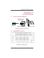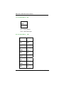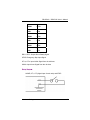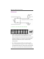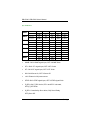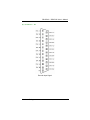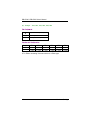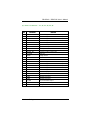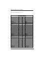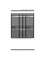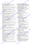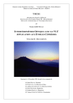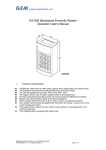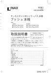
1
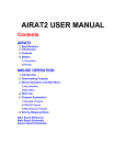
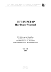
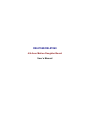
DB-87040/DB-87060 4/6 Axes Motion Daughter Board User’s Manual Disclaimers The information in this manual has been carefully checked and is believed to be accurate. AXIOMTEK Co., Ltd. assumes no responsibility for any infringements of patents or other rights of third parties which may result from its use. AXIOMTEK assumes no responsibility for any inaccuracies that may be contained in this document. AXIOMTEK makes no commitment to update or to keep current the information contained in this manual. AXIOMTEK reserves the right to make improvements to this document and/or product at any time and without notice. No part of this document may be reproduced, stored in a retrieval system, or transmitted, in any form or by any means, electronic, mechanical, photocopying, recording, or otherwise, without the prior written permission of AXIOMTEK Co., Ltd. ©Copyright 2005 by AXIOMTEK Co., Ltd. All rights reserved. October 2005, Version A1 Printed in Taiwan ii Table of Contents Chapter 1 Introduction ---------------------- iv 1.1 Specifications ...................................................... 1 Chapter 2 Hardware Setting -------------------3 2.1 System Connection Diagram ................................ 3 2.2 HARDWARE LAYOUT ......................................... 3 Table of Contents iii This page does not contain any information. iv Table of Contents DB-87040 / DB-87060 User’s Manual Chapter 1 Introduction DB-87040 and DB-87060 are a general terminal board for 4 axes and 6 axes motion controls, respectively. They are convenience and efficiency for connecting the 4/6-axes motion control card with external devices such as servo drive, encoder, local I/O and DAC signal. They are also compatible with various types of servo drive by wiring with the servo specified wiring configuration. 1.1 Specifications General Specifications Dedicated Digital input/output interface for the ASP-52504/52506 4/6 axes motion board Connector: 30-pin terminal block System I/O Signal: external RDY, STOP, HOM, OT Encoder interface for the DASP-52504/52506 motion board Connector: 25-pin D-Sub female type Signal: 4 axes or 6 axes A/B/Z encoder signal Servo /Stepper drive control command and status Connector: 4 sets or 6 sets, 25-pin D-Sub male type Signal: pulse train or Analog command, control/status Introduction 1 DB-87040 / DB-87060 User’s Manual 4-axes or 6-axes motion control wiring signals Connector: SCSI-II 100-pin pin type Signal: 4-axes or 6-axes motion control board signals Dedicated Digital Input and Output D/I Signal: HOME, OT+, OT-, STOP (Emergency Stop) D/O Signal: INH (Output Inhibits) and RDY (Servo Ready) Operation: DIP switch forced setting or normal Input Signal: Opto-isolation low active Output Signal: OPEN COLLECTOR General Environment Power: external +24V Operating Temperature: 0-60°C Storage temp: -20 to 70°C Humility: 0 to 90 non-condensing Humility: 0 to 90% Dimensions: 245 mm x 108 mm Mechanism: DIN-Rail terminal block 2 Introduction DB-87040 / DB-87060 User’s Manual Chapter 2 Hardware Setting 2.1 System Connection Diagram DDA x 6 , ENC x 6, LIO x 26, D/A x 6 DASP52506 6 servo motors DB-87060 Terminal Board (For Example: DB-87060 Terminal Board) 2.2 HARDWARE LAYOUT SW1 SW2 SW3 SW4 SW5 SW6 SW7 TB2 J7 D34 D2 D3 D4 D5 J1 D7 D8 D9 D10 D12D13D14 D15 D17D18D19 D20D22D23D24 D25D27D28D29 D30 J2 JP1 J3 JP2 J4 JP3 J5 JP4 J6 JP5 D31 D32 P1 JP6 TB1 D1 D6 D11 D16 D21 D26 DB-87060 Terminal Board Layout Hardware Setting 3 DB-87040 / DB-87060 User’s Manual (A). Terminal Block - TB1 2 DGND 1 +24V Pin 1: Power Ground Pin 2: +24V Power Input (B). Terminal Block – TB2 4 29 NC 30 NC 27 GND 28 STOP 25 RDY+ 26 RDY- 23 HOM6 24 OT+6 21 GND 22 OT-6 19 HOM5 20 OT+5 17 GND 18 OT-5 15 HOM4 16 OT+4 13 GND 14 OT-4 Hardware Setting DB-87040 / DB-87060 User’s Manual 11 HOM3 12 OT+3 9 GND 10 OT-3 7 HOM2 8 OT+2 5 GND 6 OT-2 3 HOM1 4 OT+1 1 GND 2 OT-1 RDY+, RDY-: Output Servo Ready Signal STOP: Emergency Stop Input Signal OT+n, OT-n: Input Inhibit Signal from the nth Axes HOMn: Input Home Signal from the nth Axes Wiring Diagram: HOME, OT+, OT- (digital input of each axis) and STOP Hardware Setting 5 DB-87040 / DB-87060 User’s Manual RDY digital output (C). Switch – SW1, SW2, SW3, SW4, SW5, SW6 Pin 1 Definition Default z 2 3 4 5 HOME OT+ OT- MODE INH OFF OFF OFF OFF OFF HOME : Parallel connection with TB1. HOME should be set OFF when it connected with the external HOME Sensor. The Dip Switch is simulated as the external Home Sensor when the actual external Home Sensor is not connected. Set the Dip Switch ON indicates the simulated Home Sensor is enabled and OFF indicates disable. z OT+ : Parallel connection with TB1. OT+ should be set OFF when it connected with the external OT+ Sensor. The Dip Switch is simulated as the external OT+ Sensor when the actual external OT+ Sensor is not connected. Set the Dip Switch ON indicates 6 Hardware Setting DB-87040 / DB-87060 User’s Manual the simulated OT+ Sensor is enabled and OFF indicates disable. z OT- : Parallel connection with TB1. OT- should be set OFF when it connected with the external OT- Sensor. The Dip Switch is simulated as the external OT+ Sensor when the actual external OT- Sensor is not connected. Set the Dip Switch ON indicates the simulated OT- Sensor is enabled and OFF indicates disable. z MODE : Reserved (Not Available) z INH : Parallel connection with Connector J1, J2, J3, J4, J5 and J6 of each driver. INH should be set OFF if the Servo On signal is provided by software. It should be set ON if the Servo On signal is provided by hardware device. The Dip Switch is simulated as the function of Servo On. Set the Dip Switch ON indicates the simulated Servo On signal is enabled and OFF indicates disable. Hardware Setting 7 DB-87040 / DB-87060 User’s Manual (D). Indicator Axis 1 Axis 2 Axis 3 Axis 4 Axis 5 Axis 6 Others Indicator D2 D3 D4 D5 D1 Definition HOME1 OT+1 OT-1 INH1 S_RDY1 Indicator D7 D8 D9 D10 D6 Definition HOME2 OT+2 OT-2 INH2 S_RDY2 Indicator D12 D13 D14 D15 D11 Definition HOME3 OT+3 OT-3 INH3 S_RDY3 Indicator D17 D18 D19 D20 D16 Definition HOME4 OT+4 OT-4 INH4 S_RDY4 Indicator D22 D23 D24 D25 D21 Definition HOME5 OT+5 OT-5 INH5 S_RDY5 Indicator D27 D28 D29 D30 D26 Definition HOME6 OT+6 OT-6 INH6 S_RDY6 Indicator D34 D31 D32 Definition +24V P_RDY STOP z HOME: ONÆ HOME signal input, OFFÆ HOME finish. z OT+: ONÆ OT+ signal input, OFFÆ OT+ finish. z OT-: ONÆ OT- signal input, OFFÆ OT- finish. z INH: ONÆ Servo On, OFFÆ Servo Off. z +24V: External +24V power source. z STOP: ONÆ STOP signal input, OFFÆ STOP signal finish. z P_RDY: ON( P_RDY Active, PDY+ and PDY- is shorted, OFF( P_RDY finish. z S_RDY: Controlled by Servo driver, ON( Servo Ready, OFF( Servo Off. 8 Hardware Setting DB-87040 / DB-87060 User’s Manual (E). Connector – P1 Encoder Input Signal Hardware Setting 9 DB-87040 / DB-87060 User’s Manual (F). Jumper – JP1, JP2, JP3, JP4, JP5, JP6 Pins Assignment 3 Torque Command (T.CMD) 2 DAC Output 1 Velocity Command (V.CMD) Function and Configuration Jumper JP1 JP2 JP3 JP4 JP5 JP6 1-2 short V_CMD1 V_CMD2 V_CMD3 V_CMD4 V_CMD5 V_CMD6 2-3 short T_CMD1 T_CMD2 T_CMD3 T_CMD4 T_CMD5 T_CMD6 JP1~JP6 do not setting if the servo driver is a Pulse type 10 Hardware Setting DB-87040 / DB-87060 User’s Manual (G). Driver Connector – J1, J2, J3, J4, J5, J6 No. Definition Function 1 Z+ Differential signal of Encoder Phase Z+ Input 2 A+ Differential signal of Encoder Phase A+ Input 3 B+ Differential signal of Encoder Phase B+ Input 4 PULSE+ Differential signal of Encoder Phase PULSE+ Input 5 SIGN+ Differential signal of Encoder Phase SIGN+ Input 6 COM- Digital Ground Input 7 COM- Digital Ground Input 8 COM+ +24V Input 9 SERVO_ON Connect to COM- for Servo ON 10 C_MODE Reserved 11 AGND Analog Ground 12 NC No define 13 FG Frame Ground 14 Z- Differential signal of Encoder Phase Z- Input 15 A- Differential signal of Encoder Phase A- Input 16 B- Differential signal of Encoder Phase B- Input 17 PULSE- Differential signal of Encoder Phase PULSE- Input 18 SIGN- Differential signal of Encoder Phase SIGN- Input 19 S_RDY Servo Ready Input 20 COM- Digital Ground Input 21 COM- Digital Ground Input 22 COM- Digital Ground Input 23 T_CMD Torque Command Output 24 V_CMD Velocity Command Output 25 AGND Analog Ground Hardware Setting 11 DB-87040 / DB-87060 User’s Manual (H). SCSI-II 100Pin (Pin-Type) – J7 SCSI II-100PIN CONNECTOR Definition pin pin AGND 1 51 AGND DAC/D1 2 52 DAC/D4 DAC/D2 3 53 DAC/D5 DAC/D3 4 54 DAC/D6 VCC_OUT(+5V) 5 55 COM- COM+ 6 56 COM- COM 7 57 E_STOP COM 8 58 P_RDY HOME_I1 9 59 HOME_I2 OT+_I1 10 60 OT+_I2 OT-_I1 11 61 OT-_I2 INH_O1 12 62 INH_O2 HOME_I3 13 63 HOME_I4 OT+_I3 14 64 OT+_I4 OT-_I3 15 65 OT-_I4 INH_O3 16 66 INH_O4 HOME_I5 17 67 HOME_I6 OT+_I5 18 68 OT+_I6 OT-_I5 19 69 OT-_I6 INH_O5 20 70 INH_O6 XENC_INA1 21 71 XENC_INA2 ~XENC_INA1 22 72 ~XENC_INA2 XENC_INB1 23 73 XENC_INB2 ~XENC_INB1 24 74 ~XENC_INB2 XENC_INC1 25 75 XENC_INC2 ~XENC_INC1 26 76 ~XENC_INC2 XENC_INA3 27 77 XENC_INA4 ~XENC_INA3 28 78 ~XENC_INA4 XENC_INB3 29 79 XENC_INB4 12 Definition Hardware Setting DB-87040 / DB-87060 User’s Manual SCSI II-100PIN CONNECTOR pin pin ~XENC_INB3 Definition 30 80 ~XENC_INB4 Definition XENC_INC3 31 81 XENC_INC4 ~XENC_INC3 32 82 ~XENC_INC4 XENC_INA5 33 83 XENC_INA6 ~XENC_INA5 34 84 ~XENC_INA6 XENC_INB5 35 85 XENC_INB6 ~XENC_INB5 36 86 ~XENC_INB6 XENC_INC5 37 87 XENC_INC6 ~XENC_INC5 38 88 ~XENC_INC6 XDDA_OUTA1 39 89 XDDA_OUTA2 ~XDDA_OUTA1 40 90 ~XDDA_OUTA2 XDDA_OUTB1 41 91 XDDA_OUTB2 ~XDDA_OUTB1 42 92 ~XDDA_OUTB2 XDDA_OUTA3 43 93 XDDA_OUTA4 ~XDDA_OUTA3 44 94 ~XDDA_OUTA4 XDDA_OUTB3 45 95 XDDA_OUTB4 ~XDDA_OUTB3 46 96 ~XDDA_OUTB4 XDDA_OUTA5 47 97 XDDA_OUTA6 ~XDDA_OUTA5 48 98 ~XDDA_OUTA6 XDDA_OUTB5 49 99 XDDA_OUTB6 ~XDDA_OUTB5 50 100 ~XDDA_OUTB6 *J7 connect to DASP-52504 or DASP-52506 axes control card Hardware Setting 13