1
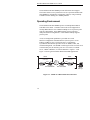
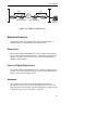
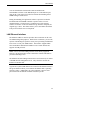
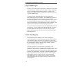
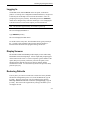
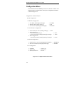
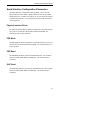
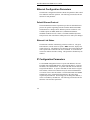
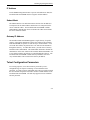
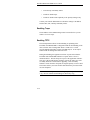
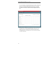
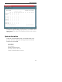
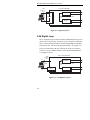
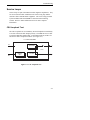
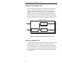
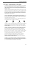
ExcaliburTM DAP
6456/SNMP
User’s Guide
15D32A-7/A
7/97
This page is blank.
ExcaliburTM DAP
6456/SNMP
User’s Guide
15D32A-7/A
7/97
Racal-Datacom, Inc.
1601 N. Harrison Parkway
P.O. Box 407044
Fort Lauderdale, FL 33340-7044
FAX: 1-954-846-5510
Internet: http://www.racal.com/rdg
Racal Data Group
Warranty
The period of warranty for the Excalibur DAP
6456/SNMP starts on the date of sale to the original end
user and extends 5 years for software and 5 years for
hardware. Refer to RACAL-DATACOM, INC.
LIMITED WARRANTY for details.
Racal-Datacom requires a Return Material Authorization
(RMA) prior to the return of any equipment under the
provisions of the warranty. Please contact your
authorized reseller or the nearest Racal support center
for details.
First Edition, July, 1997
Racal and Racal-Datacom are trademarks of Racal Electronics Plc. All other logos and
product names are trademarks or registered trademarks of their respective companies.
© 1997 Racal Datacom, Inc.
All rights reserved. No part of this work covered by the copyright hereon may
be reproduced or copied in any form or by any means — graphic, electronic, or
mechanical, including photocopying, recording, taping, or information and retrieval
systems — without written permission of the publisher. Any software furnished under
a license may be used or copied only in accordance with the terms of such license.
Racal-Datacom, Inc. reserves the right to modify or revise all or part of this document
without notice and shall not be responsible for any loss, cost, or damage, including
consequential damage, caused by reliance on these materials.
Printed in U.S.A.
ii
Racal Data Group
Customer Information Contacts
CORPORATE HEADQUARTERS
Racal-Datacom, Inc.
1601 North Harrison Parkway
Sunrise, Florida 33323-2899, U.S.A.
Tel: (954)-846-1601/(800)-333-4143
Fax: (954)-846-3935
Internet: http://www.racal.com/rdg
Call Racal’s Corporate Headquarters if you
need the following information:
Press
1
2
2
3
4
5
6
7
8
For:
Billing or Invoice information
Orders, Product Delivery or Availability
Repairs
Sales
Field Service
Returns
Employee Benefits and information
Corporate Quality
Mailing or Street Addresses
For technical support, please contact your
supplier/distributor with details of the issue.
RACAL SERVICE CONTRACT
CUSTOMERS:
For customers with Racal Service Contracts or
service requirements, contact the following offices:
AMERICAS
U.S. and U.S. Multinational
Racal-Datacom, Inc.
503 Oak Place, Suite 590
Atlanta, Georgia 30349
Tel: (404)-209-4550/(800)-366-0126
Fax: (404)-762-1547
Racal-Datacom (Canada), Inc.
2595 Skymark Avenue
Mississauga
Ontario L4W 4L5, Canada
Tel: (905)-602-7755
Fax: (905)-629-1655
EUROPE/MIDDLE EAST/AFRICA
Racal-Datacom (United Kingdom)
Landata House, Station Road
Hook, Hampshire, RG279JF, England
Tel: +44 1256 763911/+44 1256 765511
Fax: +44 1256 766463
Racal-Datacom (Belgium)
Tollaan 107A
B-1932 Sint Stevens Woluwe (Zaventum),
Belgium
Tel: +32 2725 3450
Fax: +32 2725 3609
Racal Datacom (France)
Parc du Colombier
18 rue Jules Saulnier
93206 Saint-Denis
Cedex, France
Tel: +33 14933 5800
Fax: +33 14933 5833/480 90975
Racal-Datacom (Germany)
Postfach 1651
D-63236 Neu Isenburg, Germany
Tel: +49 6102 202135
Fax: +49 6102 202157
Racal Datacom (Italy)
Via Quasimodo 12
Legnano 20025
Milano, Italy
Tel: +39 331 426111
Fax: +39 331 465722
Racal Datacom (Netherlands)
Poortweg 14
2612 PA Delft
The Netherlands
Tel: +31 15 269 8282
Fax: +31 15 262 1808
ASIA/PACIFIC
Contact your Racal affiliate support center.
(See next page for addresses and phone/fax
numbers.)
iii
RACAL AFFILIATE SUPPORT CENTERS:
AMERICAS Region
Racal-Datacom, Inc.
1601 North Harrison Parkway
Sunrise, Florida 33323-2899, U.S.A.
Tel: (954)-846-6116/(888)-RACAL4U (722-2548)
Fax: (954)-846-3692
email: [email protected]
Internet: www.racal.com/rdg/racal/ramp
EUROPE/MIDDLE EAST/AFRICA Region
Racal-Datacom, Ltd.
Landata House, Station Road
Hook, Hampshire, RG279JF, England
Tel: +44 1256 761240
Fax: +44 1256 761274
email: [email protected]
Internet: www.rdl.co.uk
Bulletin Board Service:
+44 1256 766608 (PSTN)
+44 1256 744832/3/4 (ISDN)
ASIA/PACIFIC Region
Racal-Datacom (Hong Kong), Inc.
Sun House 10th Floor
181 Des Voeux Road Central
Hong Kong
Tel: 852-2815-8633
Fax: 852-2815-8141
RDCR (Hong Kong) supports:
•
China
•
Japan
•
Korea
•
Hong Kong
•
Macao
•
Philippines
•
Taiwan
Racal Electronics (Singapore) Pte Ltd.
26 Ayer Rahah Crescent #04-06/07
Singapore 139944
Tel: +65 779 2200
Fax: +65 778 5400
RES (Singapore) supports:
•
Brunei
•
Indonesia
•
Malaysia
•
Singapore
•
Thailand
•
Rest of Indochina
Cambodia
Laos
Myanmar
Vietnam
Racal Australia PTY Ltd.
3 Powells Road
Brookvale
New South Wales 2100, Australia
Tel: +61 2 9936 7000
Fax: +61 2 9936 7036
RAPL (Sydney) supports:
•
Australia
•
Fiji
•
New Zealand
iv
About This Manual
Manual Description
The Excalibur DAP/6456 User’s Guide provides all the information you
need to properly operate and troubleshoot this unit. It assumes you are
familiar with basic data communications principles and terminology.
Refer to the Excalibur DAP/6456 Quick Start Guide for installation
instructions.
This manual is composed of the following chapters:
• Chapter 1, “Introduction” contains an overview of the Excalibur
DAP 6456/SNMP’s capabilities and descriptions of all standard
features.
• Chapter 2, “Defining Operating Parameters” explains how to
configure the Excalibur DAP 6456/SNMP so that it will perform
properly in your particular network environment. It also explains
the functions of the unit’s DIP switches.
• Chapter 3, “Online Operation” describes the different
procedures that you can perform while the Excalibur DAP
6456/SNMP is operating online. These procedures include
monitoring current operating status from five front panel LEDs and
monitoring current line status, DTE status, test status, and line
statistics from your terminal.
• Chapter 4, “Troubleshooting” describes each diagnostic test
provided by the Excalibur DAP 6456/SNMP.
• Appendix A, “Technical Specifications”
• Appendix B, “Regulatory Information”
• Appendix C, “Connector Pin and Signal Assignments”
v
About This Manual
Conventions
The following typographical conventions are used in this manual:
•
References to labeled parts of a device, such as LED indicators and
connectors are shown in boldface. For example:
The 10BT connector is located on the Excalibur DAP
6456/SNMP’s rear panel.
•
References to text that appears on your terminal screen are shown
in this font. For example:
The terminal screen displays Password >.
•
Boldface text denotes text you need to enter. For example:
Type Service.
•
[ENTER] indicates that you must press a special keyboard key, such
as Enter.
Caution: Cautions precede information that may result in
equipment damage or major failure if the given procedures are
not followed.
vi
Table of Contents
Chapter 1 - Introduction
Product Overview ...................................................................................... 1-1
Operating Environment.............................................................................. 1-2
Standard Features ...................................................................................... 1-3
Easy to Use......................................................................................... 1-3
Choice of Digital Data Service ........................................................... 1-3
Autobaud ............................................................................................ 1-3
Diagnostics ......................................................................................... 1-4
Status Monitoring ............................................................................... 1-4
Configuration Upload and Download................................................. 1-4
Software Download ............................................................................ 1-4
LAN Ethernet Interface ...................................................................... 1-5
Integral SNMP Agent ......................................................................... 1-6
Telnet Client Support ......................................................................... 1-6
Chapter 2 - Defining Operating Parameters
Overview ................................................................................................... 2-1
Setting the DIP Switches ........................................................................... 2-1
Configuring the VT100-Compatible Terminal .......................................... 2-2
Logging In ................................................................................................. 2-3
Display Screens ......................................................................................... 2-3
Restoring Defaults ..................................................................................... 2-3
Configuration Menu................................................................................... 2-4
DDS Line Configuration Parameters ......................................................... 2-5
Autobaud ............................................................................................ 2-6
DDS Line Rate ................................................................................... 2-6
External Clock .................................................................................... 2-6
Serial Interface Configuration Parameters ................................................. 2-7
Physical Interface Driver .................................................................... 2-7
PPP Mode........................................................................................... 2-7
PPP Baud............................................................................................ 2-7
SLIP Baud .......................................................................................... 2-7
Ethernet Configuration Parameters............................................................ 2-8
Default Ethernet Protocol ................................................................... 2-8
Ethernet Link Status ........................................................................... 2-8
vii
Table of Contents
IP Configuration Parameters...................................................................... 2-8
IP Address .......................................................................................... 2-9
Subnet Mask ....................................................................................... 2-9
Gateway IP Address ........................................................................... 2-9
Telnet Configuration Parameters ............................................................... 2-9
Telnet Session................................................................................... 2-10
User Name........................................................................................ 2-10
Password........................................................................................... 2-10
Login Trap........................................................................................ 2-11
TCP Retry Timeout .......................................................................... 2-11
Session Status ................................................................................... 2-11
SNMP Configuration Parameters ............................................................ 2-11
Enabling Traps ................................................................................. 2-12
Enabling TFTP ................................................................................. 2-12
Reset Unit Submenu ................................................................................ 2-13
System Firmware Menu ........................................................................... 2-13
Changing the Console Password.............................................................. 2-14
Logging Off ............................................................................................. 2-14
Chapter 3 - Online Operation
Overview ................................................................................................... 3-1
Front Panel LED Indicators ....................................................................... 3-1
Ethernet Connector LED Indicators........................................................... 3-2
Monitoring Operating Status From Your Terminal ................................... 3-3
Line Status .......................................................................................... 3-3
DTE Status ......................................................................................... 3-4
Loop Status......................................................................................... 3-4
Statistics.............................................................................................. 3-5
System Information.................................................................................... 3-7
Chapter 4 - Troubleshooting
Overview ................................................................................................... 4-1
Digital Loop Test....................................................................................... 4-1
V.54 Digital Loop...................................................................................... 4-2
Service Loops ............................................................................................ 4-3
CSU Loopback Test ........................................................................... 4-3
Non-Latching Loopback Test ............................................................. 4-4
Latching Loopback Test ..................................................................... 4-4
viii
Table of Contents
Appendix A - Technical Specifications
Appendix B - Regulatory Information
Appendix C - Connector Pin and Signal
Assignments
ix
Table of Contents
Figures
1-1
1-2
2-1
2-2
3-1
3-2
4-1
4-2
4-3
4-4
SNMP via a Direct Ethernet Connection ........................................ 1-2
SNMP via a Router Port ................................................................. 1-3
DIP Switch Settings ........................................................................ 2-1
Configuration Menu Structure ........................................................ 2-4
Front panel LED Indicators............................................................. 3-1
Ethernet Connector LED Indicators................................................ 3-3
Digital Loop Test ............................................................................ 4-2
V.54 Digital Loop Test ................................................................... 4-2
CSU Loopback Test........................................................................ 4-3
Latching and Non-Latching Loopback Tests .................................. 4-4
Tables
2-1
2-2
3-1
3-2
x
DIP Switch Settings ........................................................................ 2-2
Terminal Parameters ....................................................................... 2-2
Front Panel LED Indicator Functions ............................................. 3-2
Line Statistics.................................................................................. 3-5
Important Safety Instructions
1.
Never install telephone wiring during a lightning storm.
2.
Never install telephone jacks in wet locations unless the jack is
specifically designed for wet locations.
3.
Never touch uninsulated telephone wires or terminals unless the telephone
line has been disconnected at the network interface.
4.
Use caution when installing or modifying telephone lines.
5.
Avoid using a telephone (other than a cordless type) during an electrical
storm. There may be a remote risk of electrical shock from lightning.
6.
Do not use the telephone to report a gas leak in the vicinity of the leak.
Caution: To ensure compliance with government
regulations, do not install or operate this product until you
have read the information contained in Appendix B.
xi
Excalibur DAP 6456/SNMP
Chapter 1
Introduction
Product Overview
TM
The Excalibur Digital Access Product (DAP) 6456/Simple Network
Management Protocol (SNMP) provides a versatile, easy-to-use interface
between your data terminal equipment (DTE) and digital data service
networks. The unit is specifically designed to provide economical WAN
access for routers. It supports synchronous data transmission over fullduplex channels at speeds of 56 and 64 Kbps.
The Excalibur DAP 6456/SNMP is designed to make operation and
maintenance easy for even the most non-technical user. The unit can be
easily configured and managed via a VT100-compliant terminal interface.
Configuration parameters are minimal.
For even more comprehensive network control, the Excalibur DAP
6456/SNMP’s integral SNMP agent provides a standards-based
management interface. It allows you to manage your complete network
TM
via SNMP from either a Communications Management Series (CMS )
400, CMS 6000, or generic SNMP manager.
For management, the Excalibur DAP 6456/SNMP provides a
synchronous or asynchronous Point-to-Point Protocol (PPP)/
asynchronous Serial Line Internet Protocol (SLIP) interface and an
Ethernet (10Base-T) interface, which provides a direct connection to the
LAN. With a direct connection, you save the expense of dedicating an
expensive router port or providing an additional LAN server to route your
SNMP traffic.
A CMS 400 system provides a custom management application for
Windows. This SNMP-based application provides a sophisticated GUI
(Graphical User Interface). The application makes Excalibur DAP
6456/SNMP configuration and operation quick and intuitive.
1-1
Excalibur DAP 6456/SNMP User’s Guide
The Excalibur DAP 6456/SNMP provides full Telnet client support.
This feature allows service personnel to access a specific Excalibur DAP
6456/SNMP for configuration or diagnostic purposes, using commonly
available software running on a minimal platform.
Operating Environment
The Excalibur DAP 6456/SNMP operates on 56 Kbps Basic DDS in
Switched Carrier mode. Constant Carrier mode is also supported on
56 Kbps Basic DDS or Clear Channel 64 Kbps service in point-to-point
network configurations. Basic DDS supports point-to-point and
multipoint network configurations. Clear Channel 64 Kbps supports
point-to-point.
Access to management capabilities is provided via a Serial
Interface/Configuration Terminal Interface (SI/CTI) port or via an
Ethernet (10Base-T) port. The SI/CTI port is a synchronous/
asynchronous interface that provides access for SNMP, Telnet, and
terminal management. The SNMP or Telnet agent can be accessed via an
external router port, the Auxiliary port on a Cisco router, a terminal
server, a Racal CMS 8023, or a Racal CMS 8025. Figures 1-1 and
Figure 1-2 show typical Excalibur DAP 6456/SNMP applications.
SNMP
SNMP
Ethernet Port
Connection
Ethernet Port
Connection
Data
Router
LAN
Excalibur
DAP 6456/SNMP
DDS
Private
Line
Data
Excalibur
DAP 6456/SNMP
Router
LAN
Figure 1-1. SNMP via a Direct Ethernet Connection
1-2
SNMP
Manager
Introduction
PPP
Data
Router
PPP
DDS
Private
Line
Excalibur
DAP 6456/SNMP
Data
Excalibur
DAP 6456/SNMP
Router
LAN
LAN
SNMP
Manager
Figure 1-2. SNMP via a Router Port
Standard Features
The Excalibur DAP 6456/SNMP comes with a full complement of
standard features, as described in the following sections.
Easy to Use
The Excalibur DAP 6456/SNMP can be easily configured and managed
via a VT100-compliant terminal interface. Configuration parameters are
minimal. The unit’s service and line speed can be set automatically or
manually via the terminal.
Choice of Digital Data Service
The Excalibur DAP 6456/SNMP offers the versatility to change between
services as your needs and tariffs change. You can select 56 Kbps Basic
DDS or Clear Channel 64 Kbps service.
Autobaud
The Autobaud feature allows the Excalibur DAP 6456/SNMP to
automatically set the service and line speed upon unit reset or powerup.
With automatic detection enabled, the unit automatically configures itself
to match the type of service to which it is connected.
1-3
Excalibur DAP 6456/SNMP User’s Guide
Diagnostics
Diagnostic tests allow you to quickly isolate the source of network
malfunctions. The unit provides local digital loopback and remote V.54
digital loopback tests. The Excalibur DAP 6456/SNMP supports CSU
loopback, latching loopback, and non-latching loopback tests initiated by
the network. Additionally, the unit automatically runs an internal self-test
each time it is powered up. This test verifies the functionality of the
Excalibur DAP 6456/SNMP’s internal circuitry. Any failures cause all
the LEDs or the power LED to flash continuously.
Status Monitoring
Five LED indicators, located on the front of the unit, allow you to
monitor the Excalibur DAP 6456’s operating status at a glance. The
LEDs inform you when power is applied to the unit, when a loopback test
is active, and when a DDS line fault condition is present. Additionally,
you can view current line status, DTE status, test status, and 24-hour line
statistics from your terminal.
Configuration Upload and Download
The Excalibur DAP 6456/SNMP’s download kernel allows you to
quickly and easily upload and download the local unit’s configuration
from your terminal using Xmodem file transfer protocol over the CTI
port.
You can upload and download the local and the remote Excalibur DAP
6456/SNMP’s configuration via the PPP/SLIP port or via the Ethernet
port, using TFTP (Trivial File Transfer Protocol). This protocol provides
fast configuration uploading and downloading from a SNMP manager’s
TFTP server.
Software Download
The Excalibur DAP 6456/SNMP’s download kernel allows you to
quickly and easily download the local unit’s software from your terminal
using Xmodem file transfer protocol over the CTI port.
1-4
Introduction
You can download the local and the remote Excalibur DAP
6456/SNMP’s software via the PPP/SLIP port or via the Ethernet port,
using TFTP. This protocol provides fast software downloading from a
SNMP manager’s TFTP server.
During downloading, the application software is protected so that the
Excalibur DAP 6456/SNMP continues to operate in the event of a
download failure. The unit keeps a permanent copy of the original
software at all times. If the new download copy becomes corrupted, the
original copy is used. This feature allows you to start another download
if the previous transfer was not completed.
LAN Ethernet Interface
The Ethernet 10Base-T interface provides direct connection to the LAN
for SNMP management purposes. With a direct connection, you save the
expense of dedicating an expensive router port or providing an additional
LAN server to route your SNMP traffic. The interface supports IEEE
802.3 and Ethernet Standards for Media Access Control formats and
supports TCP/IP protocols.
Notes: Access from Token Ring networks is not directly supported.
However, the serial interface can be connected to a Racal CMS 8025 to
provide Token Ring access.
The Ethernet and Token Ring connections are used exclusively for Telnet
or SNMP network management access. They cannot be used for the
transfer of customer data.
A green and a yellow LED indicator are located on the Ethernet interface.
The green indicator allows you to monitor the Ethernet link’s operating
status at a glance. Additionally, the yellow indicator is On for short
period each time the Ethernet controller transmits a packet.
1-5
Excalibur DAP 6456/SNMP User’s Guide
Integral SNMP Agent
For those networks that require comprehensive management, testing, and
control features, the Excalibur DAP 6456/SNMP’s integral SNMP agent
provides a standards-based management interface. It allows you to
manage your complete network via SNMP from a CMS 400, CMS 6000,
or generic SNMP manager.
To simplify network management, Racal offers Excalibur DAP
6456/SNMP management for Windows. This SNMP-based application
provides an intuitive graphical interface tailored specifically for
Excalibur DAP products. You can use this application to fully configure
the Excalibur DAP 6456/SNMP, monitor its performance, and display
statistics, without having to send individual Set and Get commands. This
application runs under Racal’s CMS 400 management platform.
For your convenience, the Excalibur DAP 6456/SNMP MIB is published
on the Internet. You can download the snmp6456.ASN file from either
the Racal WWW site located at http://www.racal.com.rdg.customer/
support/mibs/mibarch.htm or the ftp located at ftp://ftp.cacal.com/pub/
mibs/snmp6456.asn.
Telnet Client Support
The Excalibur DAP 6456/SNMP provides Telnet client support.
Network management via Telnet can be performed from any workstation
in the network that has TCP/IP and a Telnet application. This feature
allows service personnel to access a specific Excalibur DAP 6456/SNMP
for configuration or diagnostic purposes, using commonly available
software running on a minimal platform.
For security purposes, access from Telnet is protected by a userconfigurable log-on sequence consisting of a user identifier and a
password. A Telnet session is established only if the log-on entries match
the user identifier and password stored in the non-volatile database of the
Excalibur DAP 6456/SNMP. The Excalibur DAP 6456/SNMP supports
only one user identifier and one password. Once the Telnet session is
established, the user may log off at any time. The Excalibur DAP
6456/SNMP allows only one Telnet session at a time. The Excalibur
DAP 6456/SNMP responds with a Busy message to additional Telnet
session requests.
1-6
Introduction
By entering commands from your terminal, you can enter the user
identifier and password required for access from Telnet, and you can
enable or disable the Login Trap feature. You can also specify the
amount of time that the TCP handler will wait for a response to data it has
sent before initiating a retry. Additionally, from your terminal, you can
enable or disable the unit from allowing a Telnet session to be
established, and you can view whether a Telnet session is active. You
can also terminate an active session.
Note: The Serial Interface Configuration parameters (physical interface
driver, PPP mode, PPP baud, and SLIP baud), IP address and Gateway
address should not be changed using Telnet. Changing these parameters
can result in losing Telnet access to the Excalibur DAP 6456/SNMP.
1-7
Chapter 2
Defining Operating Parameters
Overview
This chapter explains the functions of the Excalibur DAP 6456/SNMP’s
DIP switches and explains how to configure the unit’s operating
parameters to suit your particular network requirements. It contains a
description of each parameter to help you decide which setting is correct
for your application.
Setting the DIP Switches
Two DIP switches, labeled LP and SI/CTI, are located on the DAP
6456/SNMP’s rear panel. (See Figure 2-1.) Table 2-1 lists each switch
setting and its respective function.
Figure 2-1. DIP Switch Settings
2-1
Excalibur DAP 6456/SNMP User’s Guide
Table 2-1. DIP Switch Settings
Switch
Setting
LP
(Loop Test)
Up
Down
SI/CTI
(Serial Interface/
Configuration
Terminal
Interface)
Function Selected
Initiates a local Digital Loop test.
Terminates a local Digital Loop test.
(The “Digital Loop Test” section in
Chapter 4 provides a complete
description of this test.)
Up
Must be in this position when access to
management capabilities is provided
via a serial interface connection
(PPP/SLIP).
Down
Must be in this position when access to
management capabilities is provided
via a terminal connection and/or via an
Ethernet connection.
Configuring the VT100-Compatible Terminal
Refer to your terminal user’s manual to configure the applicable terminal
parameters, as listed in Table 2-2.
Table 2-2. Terminal Parameters
2-2
Symbol
Function
Data Bits
8
Parity
None
Speed
19,200 bps
Defining Operating Parameters
Logging In
Set the DIP switch, labeled SI/CTI on the rear panel, in the Down
position. At start-up, the Configuration Terminal Interface (CTI) process
is idle and you can attempt to access it from the terminal. If no CTI
prompt is present, press [ENTER]. The default password is SERVICE,
which can be changed at any time after initial login. The “Changing the
Console Password” section in this chapter provides instructions.
Note: The unit takes approximately 20 seconds to power-up.
The screen displays Password >.
Type SERVICE [ENTER].
The screen displays the Main menu.
To end the session at any time, from the Main menu, type 6 [ENTER] at
the -> prompt. If the terminal is idle for more than five minutes, a
timeout feature disconnects the program and logs off the user.
Display Screens
The Excalibur DAP 6456/SNMP provides display screens with readily
identifiable selections and prompts. All user inputs and prompts appear
on the bottom of the screen. To select an option, type the number of the
option, then press [ENTER]. Each time you select an option, a new
submenu appears until the lowest level menu is reached, and the
command is executed. To return from any menu to the previous menu,
press the [ESC] key.
Restoring Defaults
If, at any time, you want to reset the unit to restore the factory defaults
and start the configuration process over, from the Main menu, type 2
[ENTER]. Then type 7 [ENTER]. The screen displays the message:
Restoring defaults will reset unit! Continue? (Yes [Y]/No [N]). Type Y
[ENTER]. This restores the original factory settings, and allows you to
reconfigure the unit.
2-3
Excalibur DAP 6456/SNMP User’s Guide
Configuration Menu
The Excalibur DAP 6456/SNMP provides a tree structure of menus. The
default setting for each parameter in the System Configuration submenu
is shown in Figure 2-2.
Configuration Terminal Interface
System Configuration
1. DDS Line Configuration
1. Auto Baud (Enable[E]/Disable[D])
2. DDS Line Rate (56K[1]/64K [2])
3. External Clock (Enable[E]/Disable[D])
-> ENABLE
-> 56K
-> DISABLE
2. Serial Interface Configuration
1. Physical Interface driver (PPP[1]/SLIP[2]) -> PPP
2. PPP configuration
1. Mode (Async[1]/Sync[2])
-> Async
2. PPP baud (2400[1]/4800[2]/9600[3]/19200[4])
-> 19200
3. SLIP configuration
1. SLIP baud (2400[1]/4800[2]/9600[3]/19200[4]) -> 19200
3. Ethernet Configuration
1. Default Ethernet protocol(ETHERNET[1]/IEEE[2]) -> ETHERNET
2. Ethernet Link Status (Enable[E]/Disable[D])
-> ENABLE
4. IP Configuration
1. IP address
2. Subnet mask
3. Gateway IP address
-> 130.45.13.2
-> 255.255.0.0
-> 0.0.0.0
Figure 2-2. Configuration Menu Structure
2-4
Defining Operating Parameters
5. Telnet Configuration
1.
2.
3.
4.
5.
Telnet Session (Enable[E]/Disable[D])
User Name
Password
Login Trap (Enable[E]/Disable[D])
TCP retry timeout (seconds)
-> ENABLE
-> RACAL-DATACOM
-> SERVICE
-> ENABLE
-> 15
6. SNMP configuration
1. Primary Manager Configuration
1.
2.
3.
4.
5.
6.
Manager IP Address
Get Community
Set Community
Trap Community
Traps (Enable[E]/Disable[D])
TFTP Capability (Enable[E]/Disable[D])
-> 0.0.0.0
-> public
-> public
-> public
-> DISABLE
-> ENABLE
2. Secondary Manager Configuration
1.
2.
3.
4.
5.
Manager IP Address
Get Community
Set Community
Trap Community
Traps (Enable[E]/Disable[D])
-> 0.0.0.0
-> public
-> public
-> public
-> DISABLE
7. Restore Factory Defaults
8. Reset Unit
Figure 2-2. Configuration Menu Structure (Continued)
DDS Line Configuration Parameters
The Line Configuration submenu allows you to specify the line rate and
the source of timing signals for the Excalibur DAP 6456/SNMP’s
transmit clock. The following sections describe the function of each
parameter.
2-5
Excalibur DAP 6456/SNMP User’s Guide
Autobaud
When the Autobaud parameter is enabled, the Excalibur DAP
6456/SNMP automatically sets the service and line rate upon unit reset or
powerup. With automatic detection enabled, the unit automatically
configures itself to match the type of service to which it is connected. If
the unit is powered up with no line connected, the Autobaud parameter
defaults to 56 Kbps.
DDS Line Rate
The DDS Line Rate parameter specifies the line rate. Two options are
available:
•
56 Kbps (Basic DDS service)
•
64 Kbps (Clear Channel 64 Kbps service)
This parameter setting must correspond with your dedicated line
connection, unless the Autobaud parameter is enabled. The Excalibur
DAP 6456/SNMP operates on either service with a -45 dB minimum
receive level. The unit automatically compensates for fluctuations in the
receive level from the DDS network. The transmit level is not adjustable.
External Clock
The External Clock parameter specifies the source of timing signals for
the Excalibur DAP 6456/SNMP’s transmit clock. This clock determines
the rate at which data is transferred across the telephone line. When this
parameter is disabled, the clock is provided by the DDS network via the
receive line. When it is enabled, the unit accepts an external clock from
the DTE and uses that signal to clock the transmit data coming from the
DTE.
Notes: The External Clock option is available only when the line rate is
56 Kbps.
The clock source must be frequency locked to the network clock.
2-6
Defining Operating Parameters
Serial Interface Configuration Parameters
The Serial Interface Configuration submenu allows you to select the
physical interface driver (PPP or SLIP) and the line rate for the SNMP
management port. For PPP, it also allows you to select the mode (SLIP is
asynchronous mode only.) The following sections describe the function
of each parameter.
Physical Interface Driver
The Physical Interface Driver parameter setting must correspond with the
type of device connected to the Excalibur DAP 6456/SNMP. The
available options are PPP and SLIP.
PPP Mode
The PPP Mode parameter setting must correspond with the type of device
connected to the Excalibur DAP 6456/SNMP. The available options are
Async and Sync.
PPP Baud
The PPP Baud parameter specifies the PPP channel rate. The available
options are 2400, 4800, 9600, and 19200 bps. The default setting is
19,200 bps.
SLIP Baud
The SLIP Baud parameter specifies the SLIP channel rate. The available
options are 2400, 4800, 9600, and 19200 bps. The default setting is
19,200 bps.
2-7
Excalibur DAP 6456/SNMP User’s Guide
Ethernet Configuration Parameters
The Ethernet Configuration submenu contains the parameters that control
basic Ethernet controller operation. The following sections describe the
function of each parameter.
Default Ethernet Protocol
This Default Ethernet Protocol parameter specifies the default Ethernet
protocol for packets originating from the Excalibur DAP 6456/SNMP
and destined for a manager whose Ethernet protocol is unknown. The
available options are IEEE (IEEE 802.3) and Ethernet (Ethernet
Standards for Media Access Control). The DAP automatically honors
both protocols when it determines which protocol is used by the manager.
Ethernet Link Status
The Ethernet controller continuously performs a Link Test. The green
LED indicator, located on the rear panel’s 10BT connector, displays the
results of this test. The indicator is On when the current test indicates the
link is operational or when the Link Test is disabled. It is Off when the
current test indicates the link is failing. This parameter should always be
enabled.
IP Configuration Parameters
For the SNMP management feature to operate with Ethernet, the local
Excalibur DAP 6456/SNMP must be assigned an IP address, a Gateway
IP address, and a Subnet Mask. To operate with SLIP, the unit must be
assigned an IP address. To operate with PPP, the unit must be assigned
an IP address, which can be obtained from your network administrator.
You do not need to enter this address. The Excalibur DAP 6456/SNMP
automatically sets it in dotted decimal notation to the value that is
requested by the PPP host. Even though you can change this address, it
will be overridden by the PPP host. The following sections describe the
functions of each of these parameters.
2-8
Defining Operating Parameters
IP Address
For the SNMP management feature to operate with Ethernet or SLIP, the
Excalibur DAP 6456/SNMP must be assigned a valid IP address.
Subnet Mask
The Subnet Mask is a bit mask that indicates the bits of an IP address to
be interpreted as the subnet address and the bits to be interpreted as the
device within the subnet. The Excalibur DAP 6456/SNMP’s default
Subnet Mask is 255.255.0.0, where 255 defines the subnet and 0 defines
the device within the subnet.
Gateway IP Address
The Excalibur DAP 6456/SNMP supports a single Gateway for packet
routing. If the packet destination is on the same subnet as the Excalibur
DAP 6456/SNMP, the packets are sent directly to the destination. If it is
not on the same subnet, the packets have to be routed to the destination
through the Gateway. To enable this feature, you must enter a Gateway
IP address and a Subnet Mask. The Subnet Mask determines whether the
destination is on the same subnet as the Excalibur DAP 6456/SNMP. If it
is on a different subnet, the packets are routed through the Gateway. The
Excalibur DAP 6456/SNMP’s default Gateway IP address is 0.0.0.0.
Any valid IP address can be used for the Gateway IP address.
Telnet Configuration Parameters
For security purposes, access from Telnet is protected by a userconfigurable log-on sequence consisting of a user identifier and a
password. A Telnet session is established only if the log-on entries match
the user identifier and password stored in the non-volatile database of the
Excalibur DAP 6456/SNMP. The unit only supports one user identifier
and one password.
2-9
Excalibur DAP 6456/SNMP User’s Guide
By entering commands from your terminal, you can enter the user
identifier and password required for access from Telnet. You can enable
or disable the unit from allowing a Telnet session to be established, and
you can enable or disable the Login Trap feature. You can also specify
the amount of time that the TCP handler will wait for a response to data it
has sent before initiating a retry. Additionally, from your terminal, you
can view whether a Telnet session is active and you can terminate an
active session. The following sections explain the function of each
parameter.
Telnet Session
The Telnet Session parameter specifies whether the Excalibur DAP
6456/SNMP will allow a Telnet session to be established. The available
options are Enable and Disable.
User Name
When the Excalibur DAP 6456/SNMP is shipped from the factory, the
predefined user identifier is RACAL-DATACOM. The User parameter
allows you to change the user identifier to any alphanumeric name up to
16 characters.
Password
When the Excalibur DAP 6456/SNMP is shipped from the factory, the
predefined Telnet user password is SERVICE. The Password parameter
allows you to change the user password to any alphanumeric name up to
16 characters.
2-10
Defining Operating Parameters
Login Trap
The Login Trap parameter specifies whether an Excalibur DAP
6456/SNMP reports, via a trap to the SNMP manager, that it has
established a Telnet session. The available options are Enable and
Disable. When enabled, the Traps parameter in the Manager’s
Configuration submenu must also be enabled. If this parameter is
disabled, the manager does not receive the trap.
TCP Retry Timeout
The TCP Retry Timeout parameter specifies the amount of time, from
0 to 255 seconds, the TCP handler will wait for a response to data it has
sent before initiating a retry. The factory default setting is 15 seconds.
Note: It is recommended that you set the TCP Retry Timeout parameter
to at least 5 seconds.
Session Status
The Telnet Session Status parameter in the Telnet Status submenu allows
you to view whether a Telnet session is currently active. To do so, from
the Main menu, type 1 [ENTER]. Then type 4 [ENTER]. The screen
displays whether a Telnet session is currently active. To terminate an
active session, type 1 [ENTER].
SNMP Configuration Parameters
The SNMP Configuration submenu allows you to perform the following
functions for both a primary and secondary SNMP manager:
•
Enter the Manager’s IP address.
•
Enter the GET community names.
•
Enter the SET community names.
2-11
Excalibur DAP 6456/SNMP User’s Guide
•
Enter the trap community names.
•
Enable or disable traps.
•
Enable or disable TFTP capability to the primary manager only.
Contact your network administrator to obtain the manager’s IP address
and the GET, SET, and trap community names.
Enabling Traps
The IP address of the SNMP manager must be entered before you can
enable it to receive traps.
Enabling TFTP
The TFTP parameter allows fast downloading or uploading of the
Excalibur 6456 DAP/SNMP’s configuration and fast downloading of the
unit’s software from a management station’s TFTP server. TFTP
provides multiple SET/GET requests of SNMP objects. It can only be
enabled with one management station at a time.
During downloading, the application software is protected so that the
Excalibur DAP 6456/SNMP continues to operate in the event of a
download failure. The unit keeps two copies of the application software.
One copy is the original primary firmware version, the other copy is the
secondary firmware version used for upgrading. If the secondary
firmware version becomes corrupted, the original primary version is used.
This feature allows you to start another download if the previous transfer
was not completed.
Note: Files for configuration downloading or uploading are denoted by
*.cfg. Files for software downloading are denoted by *.ing.
2-12
Defining Operating Parameters
Reset Unit Submenu
The Reset Unit submenu allows you to initiate a soft unit reboot. From
the System Configuration menu, type 8 [ENTER]. The screen displays the
message: Are you sure you want to reset the unit? (Yes [Y]/No [N]. Type
Y [ENTER]. (Data is interrupted while the unit is reset and reinitialized.)
System Firmware Menu
The System Firmware menu allows you to download the local Excalibur
DAP 6456/SNMP’s software from your terminal using Xmodem file
transfer protocol over the CTI port. This interface operates in
asynchronous mode at 19,200 bps. When the download transfer is
complete, the unit automatically reboots to start the new operating
firmware. The default baud rate of the CTI port after rebooting is always
19,200 bps.
During downloading, the application software is protected, as previously
described in the “Enabling TFTP” section.
To start the download process, from the Main, menu type 3 [ENTER]. The
screen displays the parameter:
1. Download Secondary Firmware Using Xmodem.
Type 1 [ENTER]. The screen displays the message: Downloading
firmware will reset unit! Continue ? (Yes [Y]/No [N]. Type Y [ENTER].
The screen display prompts you to start the download process. When the
download transfer is complete, the unit automatically reboots to start the
new operating firmware. If you enter the System Firmware menu now,
two parameters appear on the screen:
1. Erase Secondary Firmware Version
2. Download Secondary Firmware Using Xmodem
2-13
Excalibur DAP 6456/SNMP User’s Guide
Changing the Console Password
When the Excalibur DAP 6456/SNMP is shipped from the factory, the
predefined console password is SERVICE. To change the predefined
password, from the Main menu, type 5 [ENTER]. The screen display
prompts you to enter the current password. Type SERVICE [ENTER].
The screen display then prompts you to enter the new password. Type
the new password. Then press [ENTER]. The new password is stored in
memory.
Logging Off
To end a terminal session at any time, from the Main menu, type 6
[ENTER] at the -> prompt. If the terminal is idle for more than five
minutes, a timeout feature disconnects the program and logs off the user.
2-14
Chapter 3
Online Operation
Overview
This chapter describes the different procedures that you can perform
while the Excalibur DAP 6456/SNMP is operating online. These
procedures include monitoring current operating status from five front
panel LEDs and monitoring current line status, DTE status, loop status,
and line statistics from your terminal.
Front Panel LED Indicators
The five labeled front panel LED indicators allow you to monitor the
DAP 6456’s operating status at a glance. The two unlabeled LED
indicators are reserved for future use. (See Figure 3-1.) Table 3-1 lists
each indicator and its respective function.
Figure 3-1. Front panel LED Indicators
3-1
Excalibur DAP 6456/SNMP User’s Guide
Table 3-1. Front Panel LED Indicator Functions
Indicator
Color
Function
PWR
(Power)
Green
On when power is applied to the unit.
LOS
(Loss of Signal)
Orange
On when the receive level is below -45 dB.
Flashes when receiving a line fault condition,
such as Out of Service (OOS), etc.
RXD
(Receive Data)
Yellow
Flashes when transitions in the receive data
stream from the DDS line are detected.
Off when in an idle state.
TXD
(Transmit Data)
Yellow
Flashes when transitions in the transmit data
stream from the DTE are detected.
Off when in an idle state.
LP
(Loop)
Yellow
On when the Excalibur DAP 6456/SNMP is in
a loopback condition (local Digital Loopback,
remote V.54 Digital Loopback, or a networkinitiated loopback).
When you plug in the Excalibur DAP 6456/SNMP, it runs an internal
self-test. Any failures cause all the LEDs or the Power LED to flash
continuously and stay in this state until you unplug the unit.
Ethernet Connector LED Indicators
The Ethernet controller continuously performs a Link Test. The green
LED indicator, located on the rear panel’s 10BT connector, displays the
results of this test. (See Figure 3-2.) The indicator is On when the
current test indicates the link is operational or when the Link Test is
disabled manually from a terminal or Telnet. It is Off when the current
test indicates the link is failing.
The yellow LED indicator on the 10BT connector is On for a short period
each time the Ethernet controller transmits a packet.
3-2
Online Operation
Figure 3-2. Ethernet Connector LED Indicators
Monitoring Operating Status From Your
Terminal
The System Status menu allows you to view the current operating status
of the dedicated line and the DTE interface signals, and allows you to
view whether any tests are in progress. It also allows you to view line
statistics for the current hour and for the past 24 hours. The following
sections describe each status submenu.
Line Status
From the Main menu, type 1 [ENTER]. Then type 1 [ENTER] again. The
screen displays the status of the dedicated line. The parameters and their
possible displays are:
Line Rate
Receiver
Receive Signal
Unknown Bipolar Violation (56K)
-> 56K/64K
-> ACTIVE/INACTIVE
-> PRESENT/NOT PRESENT
-> PRESENT/NOT PRESENT
3-3
Excalibur DAP 6456/SNMP User’s Guide
OOF Bipolar Violation (56K)
OOS Bipolar Violation (56K)
Framing (64K)
-> PRESENT/NOT PRESENT
-> PRESENT/NOT PRESENT
-> PRESENT/NOT PRESENT
DTE Status
From the Main menu, type 1 [ENTER]. Then type 2 [ENTER]. The
screen displays the status of the DTE interface signals. The parameters
and their possible displays are:
Request To Send (RTS)
-> ACTIVE/INACTIVE
Data Terminal Ready (DTR)
-> ACTIVE/INACTIVE
Clear To Send (CTS)
-> ACTIVE/INACTIVE
Data Carrier Detect (DCD)
-> ACTIVE/INACTIVE
Data Set Ready (DSR)
-> ACTIVE/INACTIVE
Receive Data DTE (RXD)
-> MARK/SPACE
Transmit Data DTE (TXD)-> MARK/SPACE
Receive Clock DTE (RXC)
-> PRESENT/NOT PRESENT
Transmit Clock DTE (TXC)
-> PRESENT/NOT PRESENT
Loop Status
From the Main menu, type 1 [ENTER]. Then type 3 [ENTER]. The
screen displays whether any tests are in progress. (The tests are
described in Chapter 4.) The parameters and their possible displays are:
Non-Latching Loop
Latch Loop
V54 Loop
CSU Loop
Bi-directional Loop
3-4
-> ACTIVE/INACTIVE
-> ACTIVE/INACTIVE
-> ACTIVE/INACTIVE
-> ACTIVE/INACTIVE
-> ACTIVE/INACTIVE
Online Operation
Statistics
The Statistics feature allows you to measure and display the quality of a
transmission line from a SNMP manager’s console, Telnet, or your
terminal. This feature provides information that allows you to measure
the amount of time your network is available for use, and allows you to
identify specific digital line problems. The Excalibur DAP 6456/SNMP
can store up to 24 hours of statistics. The statistics displays are updated
continuously in 1-second increments. Table 3-2 lists each line statistic.
Table 3-2. Line Statistics
Statistic
Receive Line Fault
Cause
Invalid receive line conditions are occurring.
Receive Level
The receive level is below -45 db.
Out of Service
Out of Service codes are being received from the
network when the Excalibur DAP 6456/SNMP is
operating at 56 Kbps.
Out of Frame
Loss of frame conditions are occurring when the
Excalibur DAP 6456/SNMP is operating at
64 Kbps.
Unknown Codes
Unknown control codes are being received from
the network.
Service Loop
A network-initiated service loop is occurring.
Network Down
Total time the network has been unavailable due to
all the line conditions.
Signal Down
Total time the network has been unavailable due to
all the line conditions, excluding service loops.
3-5
Excalibur DAP 6456/SNMP User’s Guide
To view the statistics, from the Main menu, type 1 [ENTER]. Then type 5
[ENTER]. The following display appears on the screen. The display
shows the line statistics for the current hour and for the past 12 hours.
The number of seconds the condition occurred is displayed under each
hour.
Type P [ENTER]. The following display appears on the screen. The
display shows the line statistics for the current hour and for the past
13 through 24 hours. This display shows receive line faults occurred for
4 seconds 16 hours ago.
3-6
Online Operation
To return to the previous display, Type F [ENTER]. To cancel the current
line statistics and reset them to zero, type C [ENTER] from either statistics
display screen.
System Information
To enter the System Information menu, from the Main menu, type 4
[ENTER]. The screen displays the following information about your
Excalibur DAP 6456/SNMP:
Mac Address
Part Number
Serial Number
Primary Firmware Revision
Secondary Firmware Revision
Analog Front End Firmware Revision
3-7
Chapter 4
Troubleshooting
Overview
Diagnostic tests allow you to quickly isolate the source of network
malfunctions. The Excalibur DAP 6456/SNMP provides local digital
loopback and remote V.54 digital loopback tests. Additionally, the
DAP 6456/SNMP supports CSU loopback, latching loopback, and nonlatching loopback tests initiated by the network. This chapter describes each
of these tests.
Digital Loop Test
The Digital Loop test isolates the local DTE from the rest of the network.
During this test, the DAP 6456/SNMP establishes two loops. It loops its
receiver output to its transmitter input, and its transmit data input from
the DTE to its receive data output to the DTE. (See Figure 4-1.)
To activate this test, set DIP switch LP in the Up position. To terminate
the test, set it in the Down position. This test will not be activated,
regardless of the DIP switch setting, when the LP LED is On. The LP
LED On condition indicates a remote V.54 Digital Loop test or a
network-initiated loop test is active.
4-1
Excalibur DAP 6456/SNMP User’s Guide
Local DAP 6456/SNMP
DTE
Interface
Loop
Transmitter
Interface
DAP
Loop
DTE
Lines
Receiver
Figure 4-1. Digital Loop Test
V.54 Digital Loop
The V.54 Digital Loop test differs from the standard Digital Loop test in
that it creates only one loop. It loops its receiver output to its transmitter
input. It electronically disconnects the DAP 6456/SNMP from the DTE
at the remote unit. The local unit functions normally. (See Figure 4-2.)
This test is controlled by the state of the RL pin on the V.35 interface
connector. An On condition sends the remote DAP 6456/SNMP into a
V.54 Digital Loop test.
TX
Remote DAP 6456/SNMP
DTE
Interface
Loop
Transmitter
DAP
Loop
DTE
RX
Marking
Gen
Lines
Receiver
Figure 4-2. V.54 Digital Loop Test
4-2
Troubleshooting
Service Loops
Service loops are part of the DDS network's diagnostic capabilities. They
are used to isolate trouble conditions in the local serving loop and the
customer's data communications equipment. The service loops provided
by the Excalibur DAP 6456/SNMP are described in the following
sections. Refer to AT&T Publication 62310 for more complete
information.
CSU Loopback Test
The CSU Loopback test is a mandatory network loopback test enabled by
a reversal of the local cable simplex polarity. The DDS line receive data
is looped to DDS line transmit data. At the DTE interfaces, DCD is off
and receive data is clamped to a Mark. (See Figure 4-3.)
Local DAP 6456/SNMP
TX
Transmitter
Lines
RX
Marking
Gen
Receiver
Figure 4-3. CSU Loopback Test
4-3
Excalibur DAP 6456/SNMP User’s Guide
Non-Latching Loopback Test
The Non-Latching Loopback test is an optional network loopback test.
This test is enabled by the reception of a minimum of four specific
loopback codes. It is maintained as long as every other byte contains a
loopback code, until five successive bytes are received without the
loopback indication. This test is operational in 56 Kbps DDS mode.
DDS line receive data is looped to DDS line transmit data. At the DTE
interfaces, DSR and CTS are off, and receive data is clamped to a Mark.
(See Figure 4-4.) CSU, DSU, and OCU loopbacks are supported.
Local DAP 6456/SNMP
TX
TX
Transmitter
Lines
RX
Marking
Gen
Receiver
RX
Figure 4-4. Latching and Non-Latching Loopback Tests
Latching Loopback Test
The Latching Loopback test is an optional network loopback test initiated
by the reception of a complex sequence of code bytes as defined by
AT&T Publication 62310. It is operational in Clear Channel 64 Kbps
mode. This loopback test uses the same signal routing as called for by
the Non-Latching Loopback test, except that the mapping of some return
bytes is different. Refer to AT&T Publication 62310 for this mapping.
(See Figure 4-4.)
4-4
Appendix A
Technical Specifications
Physical
Specifications
Line Requirements
Network
Configurations
Height
1.32" (3.35 cm)
Width
6.89" (17.50 cm)
Depth
9.84" (24.99 cm)
Weight
1 9 lb. (0.8 kg)
Operates on 56 Kbps Basic DDS and Clear Channel
64 Kbps services
Basic DDS service: point-to-point and multipoint
Clear Channel 64 Kbps Service: point-to-point
PPP/SLIP/Terminal
Interface
10-position jack, synchronous or asynchronous
PPP/asynchronous SLIP interface at rates of 2.4, 4.8,
9.6, and 19.2 Kbps. Can also be used as a VT100compatible terminal interface
Ethernet Interface
10-position modular jack (RJ45), Ethernet (10Base-T)
port interface
DTE Speeds
Synchronous: 56 and 64 Kbps
DTE Interface
CCITT V.35
Channel Interface
8-position keyed modular jack
Receiver Sensitivity
0 to 45 dB loop loss
A-1
Excalibur DAP 6456/SNMP User’s Guide
Carrier Mode
Constant, switched
Clocking
Slave, external
Tests
Self, local digital loopback, remote V.54 digital
loopback
Network Diagnostics
CSU loopback, latching loopback, non-latching
loopback
LED Indicators
Power, loss of signal (LOS), receive data, transmit data,
loop
DIP Switches
Two — one to enable either the VT100-compatible
terminal interface or the PPP/SLIP interface; and the
other to initiate or terminate a local digital loop test
Environmental
Ambient Temperature
32oF to 122oF (0oC to 50oC)
Relative Humidity
10% to 95% (+ 5%) noncondensing
Storage Temperature
-40oF to 158oF (-40oC to
70oC)
Power Supply
A-2
External, 100-250 VAC, 50-60 Hz, 0.3 A input current
Appendix B
Regulatory Information
FCC Part 15: Radio/Television Interference
This equipment has been tested and found to comply with the limits for a Class A
digital device, pursuant to Part 15 of the FCC Rules. These limits are designed to
provide reasonable protection against harmful interference when the equipment is
operated in a commercial environment. This equipment generates, uses, and can
radiate radio frequency energy and, if not installed and used in accordance with
the instruction manual, may cause harmful interference to radio communications.
Operation of this equipment in a residential area is likely to cause harmful
interference in which case the user will be required to correct the interference at
his own expense.
Changes or modifications to this equipment not expressly approved by RacalDatacom can void the user's authority to operate this equipment.
Special Notice
The instructions in this manual involving actions with the device and requiring a
tool* for access, must be performed only by qualified service personnel.
* A tool is defined as any implement used to facilitate a mechanical
operation, such as operating a fastener or similar fixing device.
Chaque fois que le manuel d'instructions recommande d'utiliser un outil* pour
effectuer une opèration á l'intèrieur du dispositif, cette opèration doit absolument
être confièe á un personnel de service qualifié.
* Un outil est défini tout dispositif utilisé pour faciliter une opération
mécanique, p.ex., le fonctionnement d'un organe de fixation ou autre
dispositif semblable.
B-1
Excalibur DAP 6456/SNMP User’s Guide
Notice to Canadian Users
This digital apparatus does not exceed the Class A limits for radio noise
emissions from digital apparatus as set out in the Radio Interference Regulations
of Industry Canada.
Le présent appareil numérique n`émet pas de bruits radioélectricques dépassant
les limites applicables aux appareils numériques de la Class A prescrites dans le
réglement sur le brouillage Radioélectrique édicté par le Industrie Canada.
Power Requirements
For use with a CSA certified/UL listed power supply, with NEC Class 2
output(s): rated output +5 VDC, 1.4 A, +12 VDC, 0.4 A, -12 VDC, 0.15 A.
Pour utilizer avec une alimentation CSA certifiée dotée de sortie de Classe 2 avec
characteristiques nominales de sortie +5 VDC, 1.4 A, +12 VDC, 0.4 A, -12 VDC,
0.15 A.
B-2
Regulatory Information
FCC Part 68: Requirements For End Users
This equipment complies with Part 68 of the FCC regulations. On the bottom of
the unit is an equipment label that contains, among other information, the FCC
registration number (AP3USA-31563-DE-N) and Ringer Equivalence Number
(REN), which is N.A. for this unit. If requested, provide this information to your
telephone company.
The REN is useful to determine the quantity of devices you may connect to your
telephone line and still have all of those devices ring when your number is called.
In most but not all areas, the sum of the RENs of all devices should not exceed
five (5.0). To be certain of the number of devices you may connect to your line,
as determined by the REN, call your local telephone company to determine the
maximum REN for your calling area.
An FCC compliant telephone cord and modular plug is provided with this
equipment. This equipment is designed to be connected to the telephone network
or premises wiring using a compatible modular jack which is Part 68 compliant.
See installation instructions for details.
The following are the associated private line port, jack, Facility Interface Code
(FIC), and Service Order Code (SOC) for this device:
Port
Jack
FIC
SOC
56 Kbps
RJ48S
04DU5-56
6.0F
Note that some types of analog private line connections may require the filing of a
signal power affidavit with the telephone company, and some types of digital
installations may require the filing of an "Encoded Analog Content and Billing
Protection" affidavit.
This unit cannot be used on the public coin service provided by the telephone
company. Connection to Party Line Service is subject to state tariffs. (Contact
the state public utility commission or corporation for further information.)
If the unit causes harm to the telephone network, the telephone company may
discontinue your service temporarily. If possible, you will be notified in advance.
But if advance notice is not practical, you will be notified as soon as possible.
You will be advised of your right to file a complaint with the FCC.
Your telephone company may make changes in its facilities, equipment,
operations, or procedures that could affect the proper operation of your
equipment. If they do, you will be given advance notice so as to give you an
opportunity to maintain uninterrupted service.
All repairs on your unit must be performed by the Racal Data Group company
that manufactured the unit or by an authorized representative of that company.
For service information, contact the appropriate Customer Support Office nearest
you. Contact information is listed in the front of this manual.
B-3
Excalibur DAP 6456/SNMP User’s Guide
Industry Canada: Requirements for End Users
Notice: Industry Canada identifies certified equipment. This certification means
that the equipment meets certain telecommunications network protective,
operational, and safety requirements. The Department does not guarantee the
equipment will operate to the user's satisfaction.
Before installing this equipment, users should ensure that it is permissible to be
connected to the facilities of the local telecommunications company. The
equipment must also be installed using an acceptable method of connection. The
customer should be aware that compliance with the above conditions may not
prevent degradation of service in some situations.
Repairs to certified equipment should be made by an authorized Canadian
maintenance facility designated by the supplier. Any repairs or alterations made
by the user to this equipment, or equipment malfunctions, may give the
telecommunications company cause to request the user to disconnect the
equipment.
Users should ensure for their own protection that the electrical ground
connections of the power utility, telephone lines and internal metallic water pipe
systems, if present, are connected together. This precaution may be particularly
important in rural areas.
Warning: Users should not attempt to make such connections
themselves, but should contact the appropriate electric inspection
authority, or electrician, as appropriate.
NOTICE: The Ringer Equivalence Number (REN) assigned to each terminal
device provides an indication of the maximum number of terminals allowed to be
connected to a telephone interface. The termination on an interface may consist
of any combination of devices subject only to the requirement that the sum of the
Ringer Equivalence Numbers of all the devices does not exceed 4 per port.
Repairs: Inquiries regarding Canadian repair centers should be addressed to the
Racal-Datacom company that manufactured your unit. For Canadian service
information, contact the appropriate Customer Support Office nearest you. The
office(s) are listed on page v in the front of this manual.
B-4
Appendix C
Connector Pin and Signal Assignments
Introduction
The tables in this appendix list the pin and signal assignments for the
following:
•
V.35 DTE connector
•
Dedicated line connector
•
PPP/SLIP/terminal connector
•
Ethernet 10Base-T connector
Table C-1. V.35 DTE Connector, Pin/Signal Assignments
Pin
CCITT
V.35
Symbol
Mnemonic
Input/
Output
B
102
–
–
C
105
RTS
Input
D
106
CTS
Output
Clear-to-Send
E
107
DSR
Output
Data Set Ready
F
109
RLSD
(DCD)
Output
Received Line Signal
Detector
H
108
DTR
Input
Data Terminal Ready
J
125
RI
–
Function
Signal ground
Request-to-Send
Not connected
C-1
Excalibur DAP 6456/SNMP User’s Guide
Table C-1. V.35 DTE Connector, Pin/Signal Assignments (Continued)
Pin
CCITT
V.35
Symbol
Mnemonic
Input/
Output
L
141
LL
Input
Not used
N
104
RL
Input
Remote Digital Loop
Command
P
103
TXD (A)
Input
Transmit Data
S
103
TXD (B)
Input
Transmit Data
R
104
RXD (A)
Output
Receive Data
T
104
RXD (B)
Output
Receive Data
U
113
ExTxC (A)
Input
External Transmit Clock
W
113
ExTxC (B)
Input
External Transmit Clock
V
115
RxC (A)
Output
Receiver Signal Element
Timing
X
115
RxC (B)
Output
Receiver Signal Element
Timing
Y
114
TxC (A)
Output
Transmitter Signal
Element Timing
AA
114
TxC (B)
Output
Transmitter Signal
Element Timing
NN
142
TM
Output
Test Mode
C-2
Function
Connector Pin and Signal Assignments
Table C-2. Dedicated Line Connector, Pin/Signal Assignments
Pin
No.
Signal
Input/
Output
1
Transmit Ring (R)
Output
Connection to the telephone
line, transmit side
2
Transmit Tip (T)
Output
Connection to the telephone
line, transmit side
3
No Connection
–
–
4
No Connection
–
–
5
No Connection
–
–
6
No Connection
–
–
7
Receive Tip (T1)
Input
Connection to the telephone
line, receive side
8
Receive Ring (R1)
Input
Connection to the telephone
line, receive side
Function
Table C-3. PPP/SLIP/Terminal Connector, Pin/Signal Assignments
Pin
No.
Signal
Input/
Output
–
Function
1
Not Used
2
Clock
3
Not Used
–
–
4
Ground
–
Signal ground
5
Transmit Data
Output
Output
–
EIA-232-E level
EIA-232-E level data
C-3
Excalibur DAP 6456/SNMP User’s Guide
Table C-3. PPP/SLIP/Terminal Connector, Pin/Signal Assignments
(Continued)
Pin
No.
Input/
Output
Signal
Input
Function
6
Receive Data
EIA-232-E level data
7
Not Used
–
–
8
Not Used
–
–
9
Not Used
–
–
10
Not Used
–
–
Table C-4. Ethernet 10Base-T Connector, Pin/Signal Assignments
C-4
Pin
No.
Symbol
1
TD+
Transmit Data Positive
2
TD-
Transmit Data Negative
3
RD+
Receive Data Positive
4
–
–
5
–
–
6
RD-
7
–
–
8
–
–
Function
Receive Data Negative
Index
A
Address selection
gateway...................................................................................................2-9
IP ............................................................................................................2-9
subnet mask ............................................................................................2-9
Applications (see Operating environment)
Autobaud parameter.......................................................................................2-6
C
CMS network management system................................................................1-6
Configuration
downloading and uploading via a terminal .............................................1-4
downloading and uploading via TFTP ...................................................1-4
Configuration menu
description ..............................................................................................2-4
illustration...............................................................................................2-4
Console password
changing ...............................................................................................2-14
entering...................................................................................................2-3
CSU loopback................................................................................................4-3
D
DDS Line Configuration submenu
Autobaud parameter ...............................................................................2-6
External Clock parameter .......................................................................2-6
Line Rate parameter................................................................................2-6
Dedicated line status display..........................................................................3-3
Defaults, restoring..........................................................................................2-3
Digital loop....................................................................................................4-1
DIP switches
illustration...............................................................................................2-1
settings, listed .........................................................................................2-2
Display screens ..............................................................................................2-3
Downloading software
enabling TFTP......................................................................................2-12
via a terminal ........................................................................................2-13
via TFTP...............................................................................................2-12
DTE status display.........................................................................................3-4
I-1
Index
E
Ethernet Configuration submenu
Default Ethernet Protocol parameter ......................................................2-8
Ethernet Link Status parameter...............................................................2-8
External Clock parameter ..............................................................................2-6
F
Features described .........................................................................................1-3
G
Gateway address ............................................................................................2-9
I
IP address ......................................................................................................2-9
IP Configuration submenu
Gateway IP Address parameter...............................................................2-9
IP Address parameter .............................................................................2-9
Subnet Mask parameter ..........................................................................2-9
L
Latching loopback .........................................................................................4-4
LED indicators, Ethernet connector
description ..............................................................................................3-2
illustration...............................................................................................3-3
LED indicators, front panel
functions, listed.......................................................................................3-2
illustration...............................................................................................3-1
Loop (LP) ...............................................................................................3-2
Loss of Signal (LOS) ..............................................................................3-2
Power (PWR) .........................................................................................3-2
Receive Data (RXD)...............................................................................3-2
Transmit Data (TXD) .............................................................................3-2
Line Rate parameter.......................................................................................2-6
Line statistics
description ..............................................................................................3-5
listed .......................................................................................................3-5
resetting ..................................................................................................3-7
Logging in......................................................................................................2-3
Logging off ..................................................................................................2-14
I-2
Index
Loop tests status display ................................................................................3-4
M
Monitoring operating status
dedicated line..........................................................................................3-3
DTE ........................................................................................................3-4
Ethernet connector LED indicators ........................................................3-2
front panel LED indicators .....................................................................3-1
loop tests.................................................................................................3-4
statistics ..................................................................................................3-5
N
Non-latching loopback...................................................................................4-4
O
Operating environment
description ..............................................................................................1-2
SNMP via a direct connection to the LAN, illustration ..........................1-2
SNMP via a router port, illustration .......................................................1-3
P
Password
changing console ..................................................................................2-14
entering console......................................................................................2-3
Physical Interface Driver parameter ..............................................................2-7
PPP Baud parameter ......................................................................................2-7
PPP Mode parameter .....................................................................................2-7
R
Reset Unit submenu .....................................................................................2-13
Restoring defaults ..........................................................................................2-3
S
Self-test..........................................................................................................3-2
Serial Interface Configuration submenu
Physical Interface Driver parameter .......................................................2-7
PPP Baud parameter...............................................................................2-7
PPP Mode parameter ..............................................................................2-7
SLIP Baud parameter .............................................................................2-7
I-3
Index
Service loops
CSU loopback.........................................................................................4-3
latching loopback....................................................................................4-4
non-latching loopback ............................................................................4-4
SLIP Baud parameter.....................................................................................2-7
SNMP Configuration submenu
enabling TFTP......................................................................................2-12
enabling traps .......................................................................................2-12
entering GET community names ..........................................................2-11
entering manager's IP address...............................................................2-11
entering SET community names ...........................................................2-11
entering Trap community names...........................................................2-12
Software, downloading (see Downloading software)
Statistics (see Line statistics)
Status displays (see Monitoring operating status)
Subnet mask...................................................................................................2-9
System Firmware menu................................................................................2-13
System Information menu ..............................................................................3-7
System Status menu
described.................................................................................................3-3
DTE status ..............................................................................................3-4
line status................................................................................................3-3
loop tests.................................................................................................3-4
statistics ..................................................................................................3-5
T
Telnet
description ..............................................................................................1-6
Login Trap parameter ...........................................................................2-11
Password parameter..............................................................................2-10
session status display ............................................................................2-11
TCP Retry Timeout parameter..............................................................2-11
Telnet Session parameter......................................................................2-10
terminating a session.............................................................................2-11
User Name parameter ...........................................................................2-10
Terminal
configuring .............................................................................................2-2
parameters, listed....................................................................................2-2
TFTP, enabling ............................................................................................2-12
I-4
Index
U
Unit
anlog front end firmware revision...........................................................3-7
initiating soft reboot .............................................................................2-13
Mac address............................................................................................3-7
part number.............................................................................................3-7
primary firmware revision ......................................................................3-7
secondary firmware revision...................................................................3-7
serial number ..........................................................................................3-7
V
V.54 digital loop............................................................................................4-2
I-5
Intentionally blank
We want your feedback.
To better serve our customers, Racal-Datacom welcomes your comments concerning this
manual. Please take the time to fill out the following questionnaire, remove it from your
manual, and drop it in the mail or FAX it to us at (954) 846-3935. We also welcome your
comments via e-mail at Internet address [email protected].
Name of Manual/Document No./Date:
Excalibur DAP 6456/SNMP User’s Guide 15D32A-7/A 7/97
Was the information in this manual presented in a logical order?
Excellent
Good
Fair
Poor
How easy was it to locate specific information?
Very easy
Moderately easy
Difficult
Rate the technical level of information presented in this manual:
Too technical
Suitable technical level
Not technical
enough
Are technical terms clearly defined?
Excellent
Good
Fair
Poor
Good
Fair
Poor
Fair
Poor
Rate the quality of the illustrations:
Excellent
Are the manual's instructions clearly written?
Excellent
Good
Rate the quantity of the illustrations in this manual:
Too many
Suitable amount
Not enough
Does this manual contain all the information you require? (Y/N)
If not, what would you suggest we add to make the manual more useful?
Did you find any errors in this manual? (Y/N)
If yes, please note the error and page number in the space provided below:
NAME
TITLE
COMPANY
ADDRESS
CITY
TELEPHONE NO.
STATE
(
)
ZIP
TWFM-005 - Rev B.0
7/1/95
Tape Here
FOLD
BUSINESS REPLY MAIL
FIRST CLASS MAIL PERMIT NO. 8699, FT. LAUDERDALE, FLORIDA
Postage Will Be Paid By Addressee
Racal-Datacom, Inc
Attn: Manager, Technical Writing MS-D214
Post Office Box 407044
Fort Lauderdale, FL 33340-9706
NO POSTAGE
NECESSARY
IF MAILED
IN U.S.A.