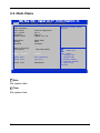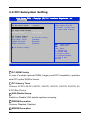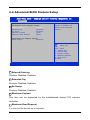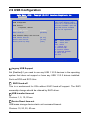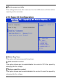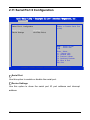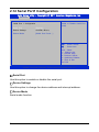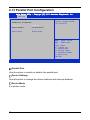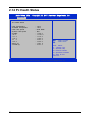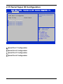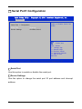
1
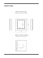
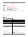
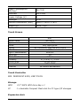
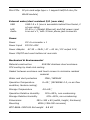
WTP-8866-15/19DPLUS User’s Manual PN: 205G00WTP88661 V1.0 Copyright 2013, ALL RIGHTS RESERVED. Greeting & Setup Thank you for purchasing the WTP-8866-15/19DPLUS Panel PC. We wish that this unit will be durable and reliable in providing your needs. Please follow the instructions below to ensure the unit continues to have high performance Unpacking After opening the carton, there will be a unit with an accessory box. Examine the contents to see if there are damages to the unit and if all accessories are present. Setting up Please read this manual carefully and remember to keep this manual for future reference. Safety Instructions & Cleaning The unit has undergone various tests in order to comply with safety standards. Inappropriate use may be dangerous. Please remember to follow the instructions below to insure your safety during the installation and operating process. Transporting & Placement of unit 1. When moving the unit on a cart; be very cautious. Quick stops, excessive forces and uneven surfaces may cause the cart to overturn thus risking the unit to fall to the ground. 2. If the Monitor display unit does fall to the ground, immediately turn the power off and disconnect cords. Then contact a service technician for repairs. Continual use of the unit may result II cause a fire or electric shock. Also, do not repair the unit on your own. 3. Before suspending the unit, make sure the material used for suspension is sturdy and stable. If not properly suspended, the display unit may fall and cause serious injury to people standing nearby as well as to the unit itself. 4. If you wish to mount the display unit, remember to use only the mounting hardware recommended by the manufacturer. Electrical and Power Source Related 1. This Monitor display unit must operate on a power source as shown on the specification label. If you are not sure what type of power supply used in the area, consult your dealer or local power supplier. 2. The power cords must not be damaged. Applied pressure, added heat, and tugging may damage the power cord. 3. The power cord must be routed properly when setup takes place. We advise that this aspect measure is to prevent people from stepping on the cords or while the unit is suspended to prevent flying objects from getting tangled with the unit. 4. Do not overload the AC outlets or extension cords. Electrical shocks or fires may occur from overloading. 5. Do not touch the power source during a thunderstorm. 6. If your hands are wet, do not touch the plug. 7. Use your thumb and index finger, grip firmly on the power cord to disconnect from the electrical socket. By pulling the power cord, may result in damaging it. 8. If the unit is not going to be in use for an extended period of III time, remember to disconnect the unit. 9. Connect the unit to a power source with the same numerical value as spec. label shown. Please use only the power cord provided by the dealer to ensure safety and EMC compliance. Various Factors of Environment 1. Having liquids seep in or inserting objects into the unit may result in electric shocks from taking and/or short circuiting the internal parts. 2. Do not place unit near heat generating sources. 3. Do not place the unit in a location where it will come in contact with fumes or steam. 4. If water has flow in or seep in, immediately disconnect power. Then contact a service technician for repairs. Servicing, Repairing, Maintenance & Safety Checks 1. If the unit is not functioning properly, observe the performance level of the display closely to determine what type of servicing is needed. 2. Do not attempt to repair the unit on your own. Disassembling the cover exposes users’ to high voltages and other dangerous conditions. Notify and request a qualified service technician for servicing the unit. 3. If any of the following situations occur turn the power source off and unplug the unit. Then contact a qualified service technician (a) The unit is soaked with liquids. (b) The unit is dropped or damaged. (c) If smoke or strange odor is flowing out of the unit. IV (d) If the power cord or plug is damaged. (e) When the functions of the unit are dysfunctional. 4. When part replacement is needed. Make sure service technician uses replacement parts specified by the manufacturer, or those with the same characteristics and performance as the original parts. If unauthorized parts are used it may result in starting a fire, electrical shock and/or other dangers. Battery Installation Follow below instructions and notice the caution for replacing and disposing of the RTC Lithium battery CR2032 for safety consideration. CAUTION: There is danger of explosion, if battery is incorrectly replaced. Replace only with the same or equivalent type recommended by the manufacturer. Dispose of used batteries according to the manufacturer’s instruction. The specification is subject to change without notice. V Version Change History Date Version 2013/10/21 V1.0 VI Description First release Remark Table of Contents System Overview(WTP-8866-15D PLUS) ...................................... 8 System View ................................................................................................... 12 System Overview (WTP-8866-19D PLUS) ................................... 13 System View ................................................................................................... 17 BIOS Setup Information ................................................................ 22 2.1 Main Menu .............................................................................................. 23 2.2 Advanced Menu ....................................................................................... 24 2.3 PCI Subsystem Setting ............................................................................ 26 2.4 Advanced BIOS Feature Setup ................................................................ 28 2.29 Password Description ............................................................................ 60 B. Wake UP on LAN Function ....................................................... 62 VII System Overview(WTP-8866-15D PLUS) System CPU Chipset Graphic Audio LAN Memory SATA AMD Fusion processor T40N AMD A55E AMD Radeon HD6320 Realtek ALC662, HD CODEC Realtek 8111E x 2 DDR3 1066 MHz (max 4G) 1 x SATA II (Max. Data Transfer Rate 300 MB/s) BIOS Brand: AMI Flash ROM size: 16M Display Brand Model Resolution (pixel) Active Area (mm) Outline Dimensions (mm) Pixel Pitch (mm) Mode Number of Colors View Angle (H/V) Brightness (cd/m2) Contrast Ratio Response Time (ms) (at 25°C) Backlight Weight (g) life time<Hrs> 8 Tianma TM150TDS50 1024x768 XGA 304.128 (W) x 228.096 (V) 326.5 (H) × 253.5 (V) × 11.8 0.297 TN 16.7M 160/160 400 600:1 8 LED 1000 50000 Touch Screen AMT 28115 resistive touch screen Resistive ( 5 wire) AMT 28115 4096x4096 Characteristics Model name Touch Resolution Stylus use possible beyond finger Glove use possible Light transmittance Hardness Response time Front Panel Protection –IP65 Touch screen Life Warranty Characteristics Characteristics No Limitation, can use any stylus Any type glove 80+-3% 3H 20 ms V 36 million activations 5 wire: 3 years Resistive ( 5 wire) Resistive ( 5 wire) Touch Controller RES PENMOUNT 6300, USB TOUCH Storage HDD CF 2.5” SATA HDD drive bay x 1 1 x bootable Compact Flash slot for CF type I/II storages Expansion slots Mini-PCIe 52 pin card-edge type x 1 support half/full size (for WLAN module) External water/dust resistant I/O (rear side) 9 USB LAN Audio USB 2.0 x 3 (one is accessible behind front bezel, 2 at rear sides) RJ-45 x 1 (Gigabit Ethernet) and PoE power input Line-out x 1, with 3.5mm phone jack connector Power Power DC-In connector x 1 Power Input DC12V~28V Power Adapter AC 90 ~ 264V / 47 ~ 63 Hz / DC output 12V, Power ON/Off and reset buttons at rear side Mechanical & Environmental Material construction SUS304 stainless steel enclosure CPU cooling by Heat sink cooling Gasket between enclosure and touch screen to minimize residual material Water and dust protection IP66 / NEMA4X Operation Temperature 0~40℃ (IEC60068-2-2, no air flow condition, fanless cooling) Storage Temperature -20~60℃ Operation Relative Humidity Storage Relative Humidity Dimensions Mounting 10%~90%, non-condensing 10%~90%, non-condensing 395 x 345 x 65 (width, height, thickness) VESA (100x100 mmxmm) WTP-8866-15D PLUS Net weight 8.8 KG WTP-8866-15D PLUS +Wall Mount net weight: 12 KG WTP-8866-15D PLUS +Wall Mount gross weight: 13.5 KG Packing list 10 1. WTP-8866-15D PLUS 2. CD-Title for driver and manual 3. Power adapter 4. Power cord 5. Options Regulatory FCC-A, CE (EMC) 11 System View 12 System Overview (WTP-8866-19D PLUS) System CPU Chipset Graphic Audio LAN Memory SATA AMD Fusion processor T40N AMD A55E AMD Radeon HD6320 Realtek ALC662, HD CODEC Realtek 8111E x 2 DDR3 1066 MHz (max 4G) 1 x SATA II (Max. Data Transfer Rate 300 MB/s) BIOS Brand: AMI Flash ROM size: 16M Display Panel AUO G190EG01 V0 Size 19" Model G190EG01 V0 Resolution (pixel) SXGA (1280 x 1024) Aspect Ratio 5:4 Active Area (mm) 376.32 (H) x 301.06(V) Pixel Pitch (mm) 0.294 Mode Normally White Number of Colors 16.7M Color Saturation (NTSC %) 72 View Angle (H/V) 170 / 160 Brightness (cd/m²) 450 (Typ. Center point) Contrast Ratio Response Time (ms) (at 25°C) 1000 : 1 (Typ) 13 5 (Typ) Power Consumption (W)(typ) Interface 26.71 W 2ch LVDS Supply Voltage (V) 5 Backlight CCFL Outline Dimensions (mm) 396.0 x 324.0 x 18.5 Weight (g) 2400 (Typ) Touch Screen Model name Type Glove Stylus Interface Light Transmission Hardness Glass thickness Linearity Active area Resolution Lifetime AMT AD-2511 5 wire RES Any type glove No Limitation, can use any stylus USB 80± 3% 3H 1.8mm X≦1.5%, Y≦1.5% 212x159.20 4096x4096 36 million activations Touch Controller RES PENMOUNT 6300, USB TOUCH Storage HDD CF 2.5” SATA HDD drive bay x 1 1 x bootable Compact Flash slot for CF type I/II storages Expansion slots 14 Mini-PCIe 52 pin card-edge type x 1 support half/full size (for WLAN module) External water/dust resistant I/O (rear side) USB LAN Audio USB 2.0 x 3 (one is accessible behind front bezel, 2 at rear sides) RJ-45 x 1 (Gigabit Ethernet) and PoE power input Line-out x 1, with 3.5mm phone jack connector Power Power DC-In connector x 1 Power Input DC12V~28V Power Adapter AC 90 ~ 264V / 47 ~ 63 Hz / DC output 12V, Power ON/Off and reset buttons at rear side Mechanical & Environmental Material construction SUS304 stainless steel enclosure CPU cooling by Heat sink cooling Gasket between enclosure and touch screen to minimize residual material Water and dust protection IP66 / NEMA4X Operation Temperature 0~40℃ (IEC60068-2-2, no air flow condition, fanless cooling) Storage Temperature -20~60℃ Operation Relative Humidity Storage Relative Humidity Dimensions Mounting 10%~90%, non-condensing 395 x 345 x 65 (width, height, thickness) VESA (100x100 mmxmm) WTP-8866-19DPLUS Net weight 15 10%~90%, non-condensing 8.8 KG WTP-8866-19DPLUS+Wall Mount net weight: 12 KG WTP-8866-19DPLUS+Wall Mount gross weight: 13.5 KG Packing list 6. WTP-8866-19DPLUS 7. CD-Title for driver and manual 8. Power adapter 9. Power cord 10. Options Regulatory FCC-A, CE (EMC) 16 System View 17 Setting up the System The following is a summary of the steps in setting up the system for use. CAUTION: Make sure that power to the system and each of the devices to be connected is switched OFF before plugging in the connectors. 1. Make any required external connections such as the keyboard, and mouse. 2. Plug the appropriate end of the power cord into the power connector of the system. Then plug the other end of the power cord to an electrical outlet. 3. Press the power switch of the system to turn on the system’s power. 4. If necessary, run the BIOS SETUP program to configure the system (see Chapter 3). 5. Install the software drivers if necessary. 18 Installing System Software Recent releases of operating systems from major vendors include setup programs, which load automatically and guide you through hard disk preparation and operating system installation. The guidelines below will help you determine the steps necessary to install your operating system on the Panel PC hard drive. NOTE: Some distributors and system integrators may have already pre-installed system software prior to shipment of your Panel PC. Installing software requires an installed HDD. Software can be loaded in the WTP-8866-15/19DPLUS Panel PC using any of below methods: Method 1: Use the Ethernet You can use the Ethernet port to download software from the net to the HDD that has been pre-installed in WTP-8866-15/19DPLUS Panel PC Method 2: Use the COM Port By connecting another PC to the WTP-8866-15/19DPLUS Panel PC with an appropriate cable, you can use transmission software to transmit Operation System Software to the HDD that has been pre-installed in the WTP-8866-15/19DPLUS Panel PC. Method 3: Use a External CD-ROM In order to boot up system from USB-CD/DVD drive, please connect USB-CD/DVD drive, turn on computer power, keep on pressing “F11” key, go into BIOS quick boot menu, select “USB-CD ROM”, WAIT FOR 20 SECONDS, then press enter, system OS will boot up from USB-CD/DVD drive directly 19 Then you can use the external CD-ROM to transmit the software to the HDD that has been pre-installed in the WTP-8866-15/19DPLUS Panel PC 20 Installing the Drivers After installing your system software, you will be able to set up the LAN, VGA, Audio and USB functions. All drivers are stored in a CD disc, which can be found in your accessory pack. The various drivers and utilities in the disc have their own text files that help users install the drivers and understand their functions. 21 BIOS Setup Information This chapter introduces BIOS setup information. Power on or reboot the system board, when screen appears message as “Press DEL to enter SETUP.” Press <DEL> to run BIOS SETUP Utility. Note: The BIOS configuration for reference only, it may subject to change without prior notice. 22 2.1 Main Menu Main Main Aptio Setup Utility - Copyright (C) 2011 American Megatrends, Inc . Advanced Chipset Boot Security Save & Exit BIOS Information BIOS Vendor Core Version Compliancy Project Version American Megatrends 4.6.4.1 UEFI 2.1 0ABVQ 0.14 x64 Model Name Revision Build Date WMIX-T56N R001 20130204 Memory Information Total Memory 4080 MB (DDR3) System Language [English] System Date System Time [Tue 02/05/2013] [10:10:10] Access Level Administrator Choose the system default language : Select Screen : Select Item Enter : Select +/- : Change Opt . F1: General Help F2: Previous Values F3: Optimized Defaults F4: Save & Exit ESC: Exit Version 2.11.1210. Copyright © 2011 American Megatrends, Inc. □ Date Set system date. □ Time Set system time. 23 2.2 Advanced Menu This section allows you to configure CPU and other system devices for basic operation through the following sub-menus. Main Aptio Setup Utility - Copyright (C) 2011 American Megatrends, Inc . Advanced Advanced Chipset Boot Security Save & Exit Legacy OpROM Support Launch PXE OpROM Launch Storage OpROM Enable or Disable Boot Option for Legacy Network Devices [Disabled] [Enabled] PCI Subsystem Settings ACPI Settings CPU Configuration IDE Configuration USB Configuration Super IO Configuration H/W Monitor Second Super IO Configuration Wake up Configuration : Select Screen : Select Item Enter : Select +/- : Change Opt . F1: General Help F2: Previous Values F3: Optimized Defaults F4: Save & Exit ESC: Exit Version 2.11.1210. Copyright © 2011 American Megatrends, Inc. □ PCI Subsyatem Settings □ ACPI Settings □ CPU Configuration □ IDE Configuration □ USB Configuration □ Super IO Configuration □ H/W Monitor □ Second Super IO Configuration □ Wake up Configuration 24 25 2.3 PCI Subsystem Setting Aptio Setup Utility - Copyright (C) 2011 American Megatrends, Inc . Advanced PCI Bus Driver Version V 2.04.00 PCI Option ROM Handling PCI ROM Priority [Legacy ROM] PCI Common Settings PCI Latency Timer VGA Palette Snoop PERR# Generation SERR# Generation In case of multiple Option ROMs (Legacy and EFI Compatible) , specifies what PCI Option ROM to launch . [32 PCI Bus Clocks] [Disabled] [Disabled] [Disabled] PCI Express Settings : Select Screen : Select Item Enter : Select +/- : Change Opt . F1: General Help F2: Previous Values F3: Optimized Defaults F4: Save & Exit ESC: Exit Version 2.11.1210. Copyright © 2011 American Megatrends, Inc. □ PCI ROM Priority In case of multiple optional ROMs (Legacy and EFI Compatible), specifies what PCI option ROM to launch. □ PCI Latency Timer Choices: 32 PCI, 64 PCI, 96 PCI, 128 PCI, 160 PCI, 192 PCI, 224 PCI, 24 8 PCI Bus Clocks. □ VGA Palette Snoop Enable or Disable VGA palette registers snooping. □ PERR# Generation Choices: Disabled, Enabled. □ SERR# Generation 26 Choices: Disabled, Enabled. 27 2.4 Advanced BIOS Feature Setup Aptio Setup Utility - Copyright (C) 2011 American Megatrends, Inc . Advanced PCI Express Device Register Settings Relaxed Ordering [Disabled] Extended Tag [Disabled] No Snoop [Enabled] Maximum Payload [Auto] Maximum Read Request [Auto] Enables or Disables PCI Express Device Relaxed Ordering. PCI Express Link Register Settings ASPM Support [Disabled] : Select Screen : Select Item Enter : Select +/- : Change Opt . F1: General Help F2: Previous Values F3: Optimized Defaults F4: Save & Exit ESC: Exit Version 2.11.1210. Copyright © 2011 American Megatrends, Inc. □ Relaxed Ordering Choices: Disabled, Enabled. □ Extended Tag Choices: Disabled, Enabled. □ No Snoop Choices: Disabled, Enabled. □ Maximum Payload This item can be supported by the motherboard chipset PCI express controller. □ Maximum Read Request It is size for the device as a requester. 28 □ ASPM Support Choices: Disabled, Enabled. 2.5 ACPI Settings Aptio Setup Utility - Copyright (C) 2011 American Megatrends, Inc . Advanced Enables or Disables BIOS ACPI Auto Configuration . ACPI Settings Enable ACPI Auto Configuration ACPI Sleep State Lock Legacy Resources S3 Video Repost [Disabled] [S3 (Suspend to RAM)] [Disabled] [Disabled] : Select Screen : Select Item Enter : Select +/- : Change Opt . F1: General Help F2: Previous Values F3: Optimized Defaults F4: Save & Exit ESC: Exit Version 2.11.1210. Copyright © 2011 American Megatrends, Inc. □ ACPI Sleep Auto Configuration Choices: Disabled, Enabled. □ Lock Legacy Resources Choices: Disabled, Enabled. □ S3 Video Repost Choices: Disabled, Enabled. 2.6 CPU Configuration 29 Aptio Setup Utility - Copyright (C) 2011 American Megatrends, Inc . Advanced Disabled for Windows XP CPU Configuration Limit CPUID Maximum PSS Support PSTATE Adjustment PPC Adjustment NX Mode SVM Mode C6 Mode Node 0 Information [Disabled] [Enabled] [PState 0] [PState 0] [Enabled] [Enabled] [Auto] : Select Screen : Select Item Enter : Select +/- : Change Opt . F1: General Help F2: Previous Values F3: Optimized Defaults F4: Save & Exit ESC: Exit Version 2.11.1210. Copyright © 2011 American Megatrends, Inc. □ Limit CPUID Maximum Choices: Disabled, Enabled. □ PSS Support Choices: Disabled, Enabled. □ PSTATE Adjustment This item is used to adjust startup P-state level, the choice is PState 0-7. □ PPC Adjustment This item is provided to adjust startup P-state level. □ NX Mode Choices: Disabled, Enabled. □ SVM Mode Choices: Disabled, Enabled. □ C6 Mode 30 It is the option to enable “C6 mode” is added to the BIOS setup. 2.7 AMD G-T56N Processor Aptio Setup Utility - Copyright (C) 2011 American Megatrends, Inc . Advanced Node0 : AMD G-T56N Processor Dual Core Running @ 1670 MHz 1350mV Max Speed : 1650 MHZ Intended Speed : 1650MHZ Min Speed : 825 MHZ Microcode Patch Level : 5000101 -------------- Cache per Core -------------L1 Instruction Cache : 32 KB/8-way L1 Data Cache : 32 KB/2-way L2 Cache : 512 KB/16-way No L3 Cache Present : Select Screen : Select Item Enter : Select +/- : Change Opt . F1: General Help F2: Previous Values F3: Optimized Defaults F4: Save & Exit ESC: Exit Version 2.11.1210. Copyright © 2011 American Megatrends, Inc. 31 2.8 IDE Configuration Aptio Setup Utility - Copyright (C) 2011 American Megatrends, Inc . Advanced IDE Configuration SATA Port0 SATA Port1 SATA Port2 SATA Port3 SATA Port4 SATA Port5 Not Present Not Present Not Present Not Present Not Present Not Present : Select Screen : Select Item Enter : Select +/- : Change Opt . F1: General Help F2: Previous Values F3: Optimized Defaults F4: Save & Exit ESC: Exit Version 2.11.1210. Copyright © 2011 American Megatrends, Inc. □ SATA Port0 □ SATA Port1 □ SATA Port2 □ SATA Port3 □ SATA Port4 □ SATA Port5 32 2.9 USB Configuration Aptio Setup Utility - Copyright (C) 2011 American Megatrends, Inc . Advanced USB Configuration USB Devices: 1 Keyboard, 1 Mouse Legacy USB Support EHCI Hand-off [Enabled] [Disabled] USB hardware delays and time-outs: USB transfer time-out [20 sec] Device reset time-out [20 sec] Device power-up delay [Auto] Enables Legacy USB support . AUTO option disables legacy support if no USB devices are connected. DISABLE option will Keep USB devices available Only for EFI applications . : Select Screen : Select Item Enter : Select +/- : Change Opt . F1: General Help F2: Previous Values F3: Optimized Defaults F4: Save & Exit ESC: Exit Version 2.11.1210. Copyright © 2011 American Megatrends, Inc. □ Legacy USB Support Set [Enabled] if you need to use any USB 1.1/2.0 devices in the operating system that does not support or have any USB 1.1/2.0 drivers installed. Such as DOS and SCO Unix. □ EHCI Hand-off This is a workaround for OSs without EHCI hand-off support. The EHCI ownership change should be claimed by EHCI driver. □ USB transfer time-out Choices: 1, 5, 10, 20 sec. □ Device Reset time-out USB mass storage device starts unit command timeout. Choices: 10, 20, 30, 40 sec. 33 □ Device power-up delay This setting determines the maximum time for USB device will take before reporting to the controller. 2.10 Super IO Configuration Aptio Setup Utility - Copyright (C) 2011 American Megatrends, Inc . Advanced Set Parameters of Serial Port 0 (COMA) Super IO Configuration Super IO Chip Winbond W83627EHG Serial Port 0 Configuration Serial Port 1 Configuration Parallel Port Configuration Watch Dog Timer [Time out Disable] CPU smart fan control [Disabled] System smart fan control [Disabled] : Select Screen : Select Item Enter : Select +/- : Change Opt . F1: General Help F2: Previous Values F3: Optimized Defaults F4: Save & Exit ESC: Exit Version 2.11.1210. Copyright © 2011 American Megatrends, Inc. □ Watch Dog Timer This option will determine watch dog timer. □ CPU smart fan control This option allows user to enable/disable the control of CPU fan speed by changing the fan voltage. □ System smart fan control This option allows user to enable/disable the control of smart fan speed by changing the fan voltage. 34 2.11 Serial Port 0 Configuration Aptio Setup Utility - Copyright (C) 2011 American Megatrends, Inc . Advanced Enable or Disable Serial Port (COM) Serial Port 0 Configuration Serial Port Device Settings [Enabled] IO=3F8h; IRQ=4; : Select Screen : Select Item Enter : Select +/- : Change Opt . F1: General Help F2: Previous Values F3: Optimized Defaults F4: Save & Exit ESC: Exit Version 2.11.1210. Copyright © 2011 American Megatrends, Inc. □ Serial Port Use this option to enable or disable the serial port. □ Device Settings Use this option to show the serial port IO port address and interrupt address. 35 2.12 Serial Port1 Configuration Aptio Setup Utility - Copyright (C) 2011 American Megatrends, Inc . Advanced Enable or Disable Serial Port (COM) Serial Port 1 Configuration Serial Port Device Settings [Enabled] IO=2F8h; IRQ=3; Device Mode [Serial Port Functi…] : Select Screen : Select Item Enter : Select +/- : Change Opt . F1: General Help F2: Previous Values F3: Optimized Defaults F4: Save & Exit ESC: Exit Version 2.11.1210. Copyright © 2011 American Megatrends, Inc. □ Serial Port Use this option to enable or disable the serial port. □ Device Settings Use this option to change the device address and interrupt address. □ Device Mode Serial mode function. 36 2.13 Parallel Port Configuration Aptio Setup Utility - Copyright (C) 2011 American Megatrends, Inc . Advanced Enable or Disable Parallel Port (LPT/LPTE) Parallel Port Configuration Parallel Port Device Settings [Enabled] IO=378h; IRQ=7 ; Device Mode [Printer Mode] : Select Screen : Select Item Enter : Select +/- : Change Opt . F1: General Help F2: Previous Values F3: Optimized Defaults F4: Save & Exit ESC: Exit Version 2.11.1210. Copyright © 2011 American Megatrends, Inc. □ Parallel Port Use this option to enable or disable the parallel port. □ Device Settings Use this option to change the device address and interrupt address. □ Device Mode It is printer mode. 37 2.14 Pc Health Status Aptio Setup Utility - Copyright (C) 2011 American Megatrends, Inc . Advanced Pc Health Status CPU Temperature SYSTEM Temperature CPU FAN Speed System FAN Speed VCORE +12 V +1.1 V +1.5 V +5 V +3.3 V VBAT (V) 3.3VSB (V) : : : : : : : : : : : : +50 C +39 C 8035 RPM N/A +1.36 V +11.51 V +1.10 V +1.52 V +5.07 V +3.32 V +3.02 V +3.32 V : Select Screen : Select Item Enter : Select +/- : Change Opt . F1: General Help F2: Previous Values F3: Optimized Defaults F4: Save & Exit ESC: Exit Version 2.11.1210. Copyright © 2011 American Megatrends, Inc. 38 2.15 Serial Super IO Configuration Aptio Setup Utility - Copyright (C) 2011 American Megatrends, Inc . Advanced Set Parameters of Serial Port 1 (COMC) Serial Super IO Configuration Super IO Chip Serial Serial Serial Serial Port Port Port Port 1 2 3 4 Fintek F81216 Configuration Configuration Configuration Configuration : Select Screen : Select Item Enter : Select +/- : Change Opt . F1: General Help F2: Previous Values F3: Optimized Defaults F4: Save & Exit ESC: Exit Version 2.11.1210. Copyright © 2011 American Megatrends, Inc. □ Serial Port 1 Configuration □ Serial Port 2 Configuration □ Serial Port 3 Configuration □ Serial Port 4 Configuration 39 □ Serial Port1 Configuration Aptio Setup Utility - Copyright (C) 2011 American Megatrends, Inc . Advanced Enable or Disable Serial Port (COM) Serial Port 1 Configuration Serial Port Device Settings [Enabled] IO=3E8h; IRQ=5; : Select Screen : Select Item Enter : Select +/- : Change Opt . F1: General Help F2: Previous Values F3: Optimized Defaults F4: Save & Exit ESC: Exit Version 2.11.1210. Copyright © 2011 American Megatrends, Inc. □ Serial Port Use this option to enable or disable the serial port. □ Device Settings Use this option to change the serial port IO port address and interrupt address. 40 □ Serial Port2 Configuration Aptio Setup Utility - Copyright (C) 2011 American Megatrends, Inc . Advanced Enable or Disable Serial Port (COM) Serial Port 2 Configuration Serial Port Device Settings [Enabled] IO=2E8h; IRQ=5; : Select Screen : Select Item Enter : Select +/- : Change Opt . F1: General Help F2: Previous Values F3: Optimized Defaults F4: Save & Exit ESC: Exit Version 2.11.1210. Copyright © 2011 American Megatrends, Inc. □ Serial Port Use this option to enable or disable the serial port. □ Device Settings Use this option to change the serial port IO port address and interrupt address. 41 □ Serial Port3 Configuration Aptio Setup Utility - Copyright (C) 2011 American Megatrends, Inc . Advanced Enable or Disable Serial Port (COM) Serial Port 3 Configuration Serial Port Device Settings [Enabled] IO=2A0h; IRQ=5; : Select Screen : Select Item Enter : Select +/- : Change Opt . F1: General Help F2: Previous Values F3: Optimized Defaults F4: Save & Exit ESC: Exit Version 2.11.1210. Copyright © 2011 American Megatrends, Inc. □ Serial Port Use this option to enable or disable the serial port. □ Device Settings Use this option to change the serial port IO port address and interrupt address. 42 □ Serial Port4 Configuration Aptio Setup Utility - Copyright (C) 2011 American Megatrends, Inc . Advanced Enable or Disable Serial Port (COM) Serial Port 4 Configuration Serial Port Device Settings [Enabled] IO=2E0h; IRQ=5; : Select Screen : Select Item Enter : Select +/- : Change Opt . F1: General Help F2: Previous Values F3: Optimized Defaults F4: Save & Exit ESC: Exit Version 2.11.1210. Copyright © 2011 American Megatrends, Inc. □ Serial Port Use this option to enable or disable the serial port. □ Device Settings Use this option to change the serial port IO port address and interrupt address. 43 2.16 Chipset Main Aptio Setup Utility - Copyright (C) 2011 American Megatrends, Inc . Advanced Advanced Chipset Boot Security Save & Exit Wake On Ring Wake On Lan [Disabled] [Enabled] Wake On Ring help : Select Screen : Select Item Enter : Select +/- : Change Opt . F1: General Help F2: Previous Values F3: Optimized Defaults F4: Save & Exit ESC: Exit Version 2.11.1210. Copyright © 2011 American Megatrends, Inc. □ Wake On Ring Choices: Disabled, Enabled. □ Wake On Lan Choices: Disabled, Enabled. 44 2.17 North Bridge Configuration Main Aptio Setup Utility - Copyright (C) 2011 American Megatrends, Inc . Advanced Chipset Chipset Boot Security Save & Exit North Bridge North Bridge LVDS Config Select South Bridge North Bridge Parameters : Select Screen : Select Item Enter : Select +/- : Change Opt . F1: General Help F2: Previous Values F3: Optimized Defaults F4: Save & Exit ESC: Exit Version 2.11.1210. Copyright © 2011 American Megatrends, Inc. □ North Bridge □ North Bridge LVDS Config Select □ South Bridge 45 2.18 North Bridge Configuration Aptio Setup Utility - Copyright (C) 2011 American Megatrends, Inc . Chipset North Bridge Configuration Primary Video Device [IGD Video] NB GPP Core Config [GPP_CORE_x4x4] Port 4 Control Port 5 Control Port 6 Control Port 7 Control [Disabled] [Disabled] [Disabled] [Disabled] IOMMU Mode Memory Clock Memory Clear [Disabled] [Auto] [Disabled] Memory Information Memory Clock : 533 MHZ Total Memory : 4080 MB (DDR3) GFX Configuration Memory Configuration Node 0 Information Select Primary Video Device That BIOS will use for output. : Select Screen : Select Item Enter : Select +/- : Change Opt . F1: General Help F2: Previous Values F3: Optimized Defaults F4: Save & Exit ESC: Exit Version 2.11.1210. Copyright © 2011 American Megatrends, Inc. □ Primary Video Device The device is IGD video. □ NB GPP Core Config The item is for NB GPP Core configuration. □ Port4 Control Choices: Disabled, Enabled. □ Port5 Control Choices: Disabled, Enabled. □ Port6 Control Choices: Disabled, Enabled. □ Port7 Control 46 Choices: Disabled, Enabled. □ IOMMU Mode Choices: Disabled, Enabled. □ Memory Clock It shows how fast this information gets distributed to the GPU □ Memory Clear Choices: Disabled, Enabled. 2.19 GFX Configuration Aptio Setup Utility - Copyright (C) 2011 American Megatrends, Inc . Chipset PCIe speed power policy GFX Configuration PSPP Policy [Balanced-Low] : Select Screen : Select Item Enter : Select +/- : Change Opt . F1: General Help F2: Previous Values F3: Optimized Defaults F4: Save & Exit ESC: Exit Version 2.11.1210. Copyright © 2011 American Megatrends, Inc. □ PSPP Policy It is set to performance mode instead of power saving mode. 47 2.20 Memory Configuration Aptio Setup Utility - Copyright (C) 2011 American Megatrends, Inc . Chipset Enabled Integrated Graphics controller Memory Configuration Integrated Graphics Bank Interleaving [Auto] [Enabled] : Select Screen : Select Item Enter : Select +/- : Change Opt . F1: General Help F2: Previous Values F3: Optimized Defaults F4: Save & Exit ESC: Exit Version 2.11.1210. Copyright © 2011 American Megatrends, Inc. □ Integrated Graphics It shares memory with the CPU, and provides economical alternative to the stand-alone card. □ Bank Interleaving Choices: Disabled, Enabled. 48 2.21 Node 0 Information Aptio Setup Utility - Copyright (C) 2011 American Megatrends, Inc . Chipset Node 0 Information Starting Address : 0 KB Ending Address : 4177979 KB Dimm0 : Not Present Dimm1 : size=4096 MB, speed=1333MHz : Select Screen : Select Item Enter : Select +/- : Change Opt . F1: General Help F2: Previous Values F3: Optimized Defaults F4: Save & Exit ESC: Exit Version 2.11.1210. Copyright © 2011 American Megatrends, Inc. 49 2.22 SB Specify INT15 options for LVDS Aptio Setup Utility - Copyright (C) 2011 American Megatrends, Inc . Chipset Specify INT15 options for LVDS DP0 Output Mode [DP-LVDS] DP1 Output Mode [Single Link DVI-D] NB PCIE Connect Type (Display device) : Select Screen : Select Item Enter : Select +/- : Change Opt . F1: General Help F2: Previous Values F3: Optimized Defaults F4: Save & Exit ESC: Exit Version 2.11.1210. Copyright © 2011 American Megatrends, Inc. □ DP0 Output Mode Use this item to enable LVDS. □ DP1 Output Mode Use this item to choose DP1 output. 50 2.23 SB Configuration Aptio Setup Utility - Copyright (C) 2011 American Megatrends, Inc . Chipset SB CIM Version : 1.1.1.1 Options for SATA Configuration SB SATA Configuration SB USB Configuration SB GPP Port Configuration SB HD Azalia Configuration : Select Screen : Select Item Enter : Select +/- : Change Opt . F1: General Help F2: Previous Values F3: Optimized Defaults F4: Save & Exit ESC: Exit Version 2.11.1210. Copyright © 2011 American Megatrends, Inc. 51 2.24 SATA Configuration Aptio Setup Utility - Copyright (C) 2011 American Megatrends, Inc . Chipset OnChip SATA Channel OnChip SATA Type OnChip IDE mode SATA IDE Combined Mode Combined Mode Option [Enabled] [Native IDE] [Legacy mode] [Enabled] [SATA as primary] SATA ESP on PORT0 SATA ESP on PORT1 SATA ESP on PORT2 SATA ESP on PORT3 SATA ESP on PORT4 SATA ESP on PORT5 SATA Power on PORT0 SATA Power on PORT1 SATA Power on PORT2 SATA Power on PORT3 SATA Power on PORT4 SATA Power on PORT5 [Disabled] [Disabled] [Disabled] [Disabled] [Disabled] [Disabled] [Enabled] [Enabled] [Enabled] [Enabled] [Enabled] [Enabled] Enable or Disable Serial ATA : Select Screen : Select Item Enter : Select +/- : Change Opt . F1: General Help F2: Previous Values F3: Optimized Defaults F4: Save & Exit ESC: Exit Version 2.11.1210. Copyright © 2011 American Megatrends, Inc. □ OnChip SATA Channel Choices: Disabled, Enabled. □ OnChip SATA Type The default is Native IDE. □ OnChip IDE Mode The option is Legacy mode or Native mode. □ SATA IDE Combined Mode Choices: Disabled, Enabled □ Combined Mode Option The option is set to be “SATA as primary.” □ SATA ESP on PORT0 52 Choices: Disabled, Enabled □ SATA ESP on PORT1 Choices: Disabled, Enabled □ SATA ESP on PORT2 Choices: Disabled, Enabled □ SATA ESP on PORT3 Choices: Disabled, Enabled □ SATA ESP on PORT4 Choices: Disabled, Enabled □ SATA ESP on PORT5 Choices: Disabled, Enabled □ SATA Power on PORT0 Choices: Disabled, Enabled □ SATA Power on PORT1 Choices: Disabled, Enabled □ SATA Power on PORT2 Choices: Disabled, Enabled □ SATA Power on PORT3 Choices: Disabled, Enabled □ SATA Power on PORT4 Choices: Disabled, Enabled □ SATA Power on PORT5 Choices: Disabled, Enabled 53 2.25 USB Port Aptio Setup Utility - Copyright (C) 2011 American Megatrends, Inc . Chipset USB USB USB USB USB Port Port Port Port Port 0 1 2 3 4 [Enabled] [Enabled] [Enabled] [Enabled] [Enabled] USB USB USB USB USB Port Port Port Port Port 5 6 7 8 9 [Enabled] [Enabled] [Enabled] [Enabled] [Enabled] USB USB USB USB USB USB Port Port Port Port Port Port 10 11 12 13 FL0 FL1 [Enabled] [Enabled] [Enabled] [Enabled] [Enabled] [Enabled] Enable or Disable USB PORT 0 : Select Screen : Select Item Enter : Select +/- : Change Opt . F1: General Help F2: Previous Values F3: Optimized Defaults F4: Save & Exit ESC: Exit Version 2.11.1210. Copyright © 2011 American Megatrends, Inc. □ OHCI HC (Bus 0 Dev 18 Fn 0) Choices: Disabled, Enabled □ OHCI HC (Bus 0 Dev 19 Fn 0) Choices: Disabled, Enabled □ OHCI HC (Bus 0 Dev 22 Fn 5) Choices: Disabled, Enabled □ USB Port 0 Choices: Disabled, Enabled □ USB Port 1 Choices: Disabled, Enabled □ USB Port 2 54 Choices: Disabled, Enabled □ USB Port 3 Choices: Disabled, Enabled □ USB Port 4 Choices: Disabled, Enabled □ USB Port 5 Choices: Disabled, Enabled □ USB Port 6 Choices: Disabled, Enabled □ USB Port 7 Choices: Disabled, Enabled □ USB Port 8 Choices: Disabled, Enabled □ USB Port 9 Choices: Disabled, Enabled □ USB Port 10 Choices: Disabled, Enabled □ USB Port 11 Choices: Disabled, Enabled □ USB Port 12 Choices: Disabled, Enabled □ USB Port 13 Choices: Disabled, Enabled □ USB Port FL0 Choices: Disabled, Enabled □ USB Port FL1 Choices: Disabled, Enabled 55 2.26 SB GPP Function Configuration Aptio Setup Utility - Copyright (C) 2011 American Megatrends, Inc . Chipset SB GPP Function GPP Port Link Configuration [Enabled] [1:1:1:1 mode] Enable or Disable SB GPP Function : Select Screen : Select Item Enter : Select +/- : Change Opt . F1: General Help F2: Previous Values F3: Optimized Defaults F4: Save & Exit ESC: Exit Version 2.11.1210. Copyright © 2011 American Megatrends, Inc. □ SB GPP Function Choices: Disabled, Enabled □ GPP Port Link Configuration Choices: Disabled, Enabled 56 2.27 Azalia Device Configuration Aptio Setup Utility - Copyright (C) 2011 American Megatrends, Inc . Chipset HD Audio Azalia Device [Audio] Enable or Disabled HD Audio Azalia Device : Select Screen : Select Item Enter : Select +/- : Change Opt . F1: General Help F2: Previous Values F3: Optimized Defaults F4: Save & Exit ESC: Exit Version 2.11.1210. Copyright © 2011 American Megatrends, Inc. □ HD Audio Azalia Device 57 2.28 Boot Configuration Main Aptio Setup Utility - Copyright (C) 2011 American Megatrends, Inc . Advanced Chipset Boot Boot Security Save & Exit Boot Configuration Setup Prompt Timeout Bootup NumLock State [On] Quiet Boot Fast Boot [Disabled] [Disabled] CSM16 Module Verison 07.64 GateA20 Active Option ROM Messages Interrupt 19 Capture [Upon Request] [Force BIOS] [Disabled] Boot Option Priorities Boot Option #1 Boot Option #2 [SATA: TOSHIBA MK25...] [UEFI: Built-in EFI…] 1 Hard Drive BBS Priorities Number of seconds to wait for setup activation key. 65535(0xFFFF) means indefinite waiting. : Select Screen : Select Item Enter : Select +/- : Change Opt . F1: General Help F2: Previous Values F3: Optimized Defaults F4: Save & Exit ESC: Exit Version 2.11.1210. Copyright © 2011 American Megatrends, Inc. □ Setup Prompt Timeout This setting is to remind when the system is waiting for setup activation key. □ Bootup NumLock State This setting is to set Num Lock status when the system is powered on. Setting to [On] will turn on the Num Lock key when the system is powered on. Setting to [Off] will allow users to use the arrow keys on the numeric keypad. Choices: On, Off. □ Quiet Boot This item can help to select the screen display when the system boots. □ GateA20 Active Upon request GA20 can be disabled using BIOS services. 58 □ Option ROM Messages Set display mode for option ROM. □ Interrupt 19 Capture Enable: Allow option ROMs to trap into 19. Choices: Disabled, Enabled. 59 2.29 Password Description Main Aptio Setup Utility - Copyright (C) 2011 American Megatrends, Inc . Advanced Chipset Boot Security Security Save & Exit Password Description Set Administrator Password If ONLY the Administrator’s password is set , then this only limits access to Setup and is only asked for when entering Setup If ONLY the User’s password is set, then this is a power on password and must be entered to boot or enter Setup. In Setup the User will have Administrator rights. The password must be 3 to 20 characters long. Administrator Password User Password : Select Screen : Select Item Enter : Select +/- : Change Opt . F1: General Help F2: Previous Values F3: Optimized Defaults F4: Save ESC: Exit Version 2.11.1210. Copyright © 2011 American Megatrends, Inc. 60 2.30 Save Changes and Exit Main Aptio Setup Utility - Copyright (C) 2011 American Megatrends, Inc . Advanced Chipset Boot Security Save Exit Save && Exit Save Changes and Exit Discard Changes and Exit Save Changes and Reset Discard Changes and Reset Restore/Load Default values For all the setup options. Save Options Save Changes Discard Changes Restore Defaults Save as User Defaults Restore User Defaults Boot Override Launch EFI Shell from file system device : Select Screen : Select Item Enter : Select +/- : Change Opt . F1: General Help F2: Previous Values F3: Optimized Defaults F4: Save & Exit ESC: Exit Version 2.11.1210. Copyright © 2011 American Megatrends, Inc. 61 B. Wake UP on LAN Function Please make sure the AC power is ON before use the function. 1. Boot into OS (windows XP). 2. In start menu control panel System device manager Network adapters double click Marvell Yukon 88E8071 Advance Wake from Shutdown Item select Wake on Magic packet from power off state. 62 63