1
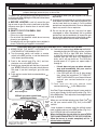
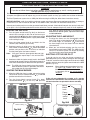
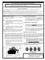
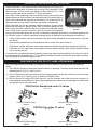
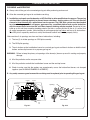
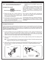
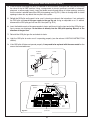
OWNER’S
MANUAL
G9 SERIES VENT-FREE GAS LOG SET INSTRUCTIONS
FOR NATURAL OR PROPANE GAS
Burner Systems:
G9-20/24/30(P)
G9-20/24/30-12(M)(P)
G9-20/24/30-15(M)(P)
DESIGN CERTIFIED
Log Sets:
to
Unvented Room Heater Standard
ANSI Z21.11.2-2007
and
Vented Decorative Appliance
ANSI Z21.60b-2004
Golden Oak Designer (RD9)
Split Oak (S9)
Forest Oak (FO9)
WARNING
If the information in this manual is not
followed exactly, a fire or explosion
may result, causing property damage,
personal injury, or loss of life.
Do not store or use gasoline or other
flammable vapors and liquids in the vicinity
of this or any other appliance.
WHAT TO DO IF YOU SMELL GAS:
• Open a window.
• Do not try to light any appliance.
• Do not touch any electrical switch; do
not use any phone in the building.
• Immediately call the gas supplier
from a neighbor’s phone. Follow gas
supplier’s instructions.
• If you cannot reach the gas supplier,
call the fire department.
Installation and service must be performed by a
qualified professional installer, service agency,
or the gas supplier.
INSTALLER: Leave this manual with the appliance.
CONSUMER: Retain for future reference.
Important:
Read this manual carefully before
starting installation of the log set.
This appliance may be installed in an aftermarket,
permanently located, manufactured (mobile) home,
where not prohibited by local codes.
This appliance is only for use with the type of gas
indicated on the rating plate. This appliance is not
convertible for use with other gasses.
This is an unvented gas-fired heater. It uses air (oxygen)
from the room in which it is installed. Provisions for
adequate combustion and ventilation air must be
provided. Refer to the section entitled VENTILATION
AND CONFINED SPACE INFORMATION.
This appliance is designed as an “attended appliance.”
Adults must be present when the unit is operating. Do
not leave this unit burning when unattended or while
anyone is sleeping.
Installation/service MUST be performed by an NFI
Certified or other qualified professional installer or
service agency who is familiar with important safety
information applicable to vent-free gas log heaters,
and with current provisions of ANSI 223.1/NFPA54 and
pertinent codes.
This gas log set must be installed in accordance with local
codes and ordinances, or in the absence of local codes,
with either the latest National Fuel Gas Code (ANSI
Z223.1/NFPA 54), or Natural Gas and Propane Storage
and Handling Installation Code (CSA-B149.1).
ROBERT H. PETERSON CO. • 14724 East Proctor Avenue, City of Industry, CA 91746
REV 5 - 0812090904
1
NO. L-F2-06808
TABLE OF CONTENTS
G9 SPECIFICATIONS AND REQUIREMENTS
PRE-INSTALLATION AND FIREPLACE PREPARATION SAFETY
IMPORTANT SAFETY INFORMATION
INSTALLATION SAFETY INFORMATION
INSTALLATION SAFETY GUIDELINES
OPERATIONAL SAFETY INFORMATION
VENTILATION AND CONFINED SPACE SAFETY INFORMATION
MINIMUM CLEARANCE TO COMBUSTIBLES
BURNER PARTS LIST
WHEN USED AS A VENTED DECORATIVE APPLIANCE (PER ANSI Z21.60b-2004)
INSTALLATION
CONNECTING THE GAS TO THE BURNER SYSTEM
CHECKING GAS PRESSURE
GAS PRESSURE SPECIFICATIONS
LOGS - PARTS LIST
LOG PLACEMENT
GLOWING EMBERS PLACEMENT
LAVA-FYRE™ GRANULES PLACEMENT
CONTROL SETTINGS
LIGHTING INSTRUCTIONS - SERIES 12 VALVE
LIGHTING INSTRUCTIONS - SERIES 15 VALVE
LIGHTING THE ODS PILOT
ADJUSTING THE FLAME HEIGHT
LIGHTING INSTRUCTIONS - MANUAL VALVE
LIGHTING THE ODS PILOT
IGNITING THE MAIN BURNER
ADJUSTING THE FLAME HEIGHT
SHUTTING OFF THE ODS PILOT
OPERATING THE UNVENTED GAS LOG SET
CHECKING THE ODS PILOT FLAME APPEARANCE
CLEANING AND SERVICING
CLEANING THE LOG SET
CLEANING THE ODS PILOT
LOG SET NOTES PAGE
TROUBLESHOOTING
FLAME DESCRIPTION
WARRANTY
REV 5 - 0812090904
2
3
4
5
6
6
7
9
10
11
12
12
12
14
14
15
16
17
17
18
19
20
20
20
21
21
21
21
21
22
22
23
24
24
26
27
29
30
NO. L-F2-06808
G9 SPECIFICATIONS AND REQUIREMENTS
Fig. 3-1
APPROVED INSTALLATIONS
Subject to minimum fireplace size requirements
specified below:
1. Solid-fuel-burning fireplaces;
A) Prefabricated fireplaces listed to UL-127
B) All other masonry fireplaces
Rear
width
Height
HEIGHT
DEPTH
Depth
2. Universal-listed vent-free fireplaces.
Note: Installation in any other fireplace is prohibited
and will void any approvals and warranties.
Front
FR ONT
width
WIDTHopening
OPENING
Fireplace dimensions
FIREPLACE SIZE REQUIREMENTS AND BTU RATING
INFORMATION
The minimum size of FIREPLACE for installation
of this G9 unvented gas log set is:
Log
set
size
Width
BTU rating
High setting
Low setting
Depth
Height
Millivolt
valve
Manual
valve
Millivolt
valve
Manual
valve
31" front
22" rear
14"
18"
36,000
36,000
21,000
17,000
29" front
20" rear
31" front
22" rear
14"
18"
36,000
36,000
21,000
17,000
34" front
26" rear
40" front
29" rear
14"
18"
36,000
36,000
21,000
17,000
Manual
valve
Millivolt
valve
20"
24" front
20" rear
24"
30"
G9 Series vent-free gas log sets are available with a This gas log set has been certified to two standards:
variable flame-height control valve that can be used UNVENTED ROOM HEATER-ANSI Z21.11.2-2007
with the optional remote transmitter and receiver.
VENTED DECORATIVE APPLIANCE-ANSI Z21.60b-2004
A spark ignition system (piezo) allows the gas ODS pilot
to be lit without the use of matches, and permits the Check local or state codes to determine if vent-free
heaters are permitted in the locality before you install
operation of the appliance during a power outage.
this log set as a vent-free appliance. If not permitted,
This vent-free gas log set is equipped with an Oxygen you may install and operate this log set as a vented
Depletion Sensor (ODS) safety pilot system. The appliance.
ODS pilot senses the amount of oxygen available in
the room and shuts the log set off before the oxygen State or local codes may only allow operation of this
level drops below 18%. The ODS pilot can only be relit appliance in a vented configuration. Check your state
when fresh air is available. This may require opening or local codes.
a window or a door to another room or cracking
the damper open slightly.
Important: For safe operation and proper performance of this product and to comply with certification, listings,
and building code acceptances, use ONLY Peterson Real-Fyre® controls, parts, and accessories
that have been specifically listed or certified for use with this burner system. Use of other controls,
parts, or accessories is prohibited and will void all warranties, certifications, listings, and building
code approvals, and may cause property damage, personal injury, and loss of life.
REV 5 - 0812090904
3
NO. L-F2-06808
PRE-INSTALLATION AND FIREPLACE PREPARATION SAFETY
CAUTION: Installation and repair must be done by a qualified professional installer.
Installer:
Carefully read these instructions before installing this gas burner system. Be sure you understand
all safety precautions and warnings contained in this manual.
A. This appliance is only for use with the type of gas indicated on the rating plate. This appliance is NOT
CONVERTIBLE for use with other gasses.
B. CAUTION: If not installed, serviced, and used correctly per these instructions, this product can cause
serious personal injury, property damage, or loss of life.
PRE-INSTALLATION AND FIREPLACE PREPARATION SAFETY GUIDELINES
C. WARNING: Before installing in a solid-fuel-burning fireplace, the chimney flue, damper, and firebox must
be thoroughly CLEANED of soot, creosote, ashes, and loose paint by a qualified chimney cleaner. Some
fireplaces (especially older ones) may need repair prior to installing this appliance.
D. CHECK GAS TYPE (natural or propane): The gas supply must be the same as stated on your burner system
rating plate. If gas supply is different, DO NOT INSTALL. Contact your dealer for immediate assistance.
E. Any outside air ducts and/or ash dumps located on the floor or walls of the fireplace must be permanently
sealed shut before the installation. Use a heat-resistant sealant. Do not seal the chimney flue damper.
F. INSUFFICIENT GAS PRESSURE WILL KEEP THE ODS (OXYGEN DEPLETION SENSOR) PILOT
FROM OPERATING PROPERLY. DO NOT USE IF GAS PRESSURE IS LOWER THAN THE MINIMUM
REQUIREMENT.
G. The minimum inlet gas-supply pressure for purposes of input adjustment is 5" water column (w.c.) on natural
gas and 11" w.c. on propane gas. Insufficient gas pressure will affect proper operation of the ODS pilot. Do
not install this gas appliance if minimum pressure is not available. The maximum inlet gas-supply pressure
is 10.5" w.c. on natural gas and 13" w.c. on propane gas. The propane source must be regulated. (Do not
connect this appliance directly to an unregulated propane gas tank - this can cause an explosion.)
H. The gas piping system must be sized to provide minimum inlet pressure at the maximum flow rate (BTU/
hr). Undue pressure loss will occur if the pipe is too small, or the run is too long.
I. The minimum clearance from the fireplace opening to combustible materials on side walls and ceiling must
be maintained as outlined in MINIMUM CLEARANCE TO COMBUSTIBLES - WALLS AND CEILING.
J. At least 10"-12" of noncombustible or heat-resistant material is required above the fireplace. A fireplace
hood will be required to act as a heat deflector in protecting combustible fireplace surrounds (facing and/or
mantel) if certain minimum clearances cannot be met.
K. Be certain that combustible flooring material (i.e., carpet, tile, etc.) is not too close to this gas appliance. If
this appliance is at floor level or less than 6" above the floor, there must be at least 12" of noncombustible
material between the base of the fireplace and any combustible flooring.
L. Input ratings shown in BTU per hour are for elevations up to 2,000 ft. For elevations above 2,000 ft., refer to
the National Fuel Gas Code or contact the Robert H. Peterson Company before installing this product.
M. This gas appliance and its main gas valve must be disconnected from the gas-supply piping system during
any pressure testing of that system at test pressures in excess of 1/2 psig.
N. This gas appliance must be isolated from the gas-supply piping system by closing the equipment shutoff
valve connected to the gas-supply line during any pressure testing of the gas-supply piping system at test
pressures equal to or less than 1/2 psig.
O. Do not use this appliance if any part has been underwater. Immediately call a qualified service technician
to inspect the appliance and to replace any part of the control system and any gas control that has been
underwater.
WARNING
THIS APPLIANCE IS EQUIPPED FOR (NATURAL OR PROPANE) GAS.
FIELD CONVERSION IS NOT PERMITTED.
4
IMPORTANT SAFETY INFORMATION
ANSI Z21.11.2-2007 UNVENTED ROOM HEATER GENERAL SAFETY INFORMATION
A. WARNING: CARBON MONOXIDE POISONING MAY LEAD TO DEATH.
When used without fresh air, gas appliances may give off carbon monoxide, an odorless,
colorless, poisonous gas. Early signs of carbon monoxide poisoning are similar to the flu, with
headaches, dizziness, and/or nausea. If you have these signs, the gas appliance may not be
installed correctly, or may not be working properly. GET FRESH AIR AT ONCE! STOP USING THE
APPLIANCE IMMEDIATELY! Have the appliance serviced before use continues. Some people,
including pregnant women; persons with heart or lung disease, asthma, or anemia; those under
the influence of alcohol; and persons at high altitudes, are more affected by carbon monoxide
than others.
If there are ANY signs of carbon monoxide, GET FRESH AIR AT ONCE! STOP USING THIS
APPLIANCE IMMEDIATELY!
B. If any soot appears on the appliance or other areas of the fireplace in which this appliance is
installed, shut system off and call a qualified professional service technician, vent-free gas log
technician, or your local gas company.
C. WHEN INSTALLING AS A DECORATIVE VENTED APPLIANCE, THE UNIT MUST CONFORM
TO ALL LOCAL CODES AND TO THE LATEST EDITION OF THE NATIONAL FUEL GAS CODE ANSI
Z223.1/NFPA54.
D. This appliance may be installed in an aftermarket, permanently located, manufactured (mobile)
home where not prohibited by local codes. Installation of appliances designed for manufactured
homes or mobile homes must conform with the Manufactured Home Construction and Safety
Standard, Title 24 CFR, Part 3280 in the U.S.; or with CAN/CSA Z240 MH, Mobile Housing in
Canada; or with ANSI/NCSBCS A225.1/NFPA 501A, Manufactured Home Installations Standard
when none of the previously referenced standard are applicable.
E. Eliminate drafts before using the gas appliance by closing heating and air conditioning vents,
returns, and outside air vents. Fans blowing directly into the fireplace must be turned off when
this appliance is operating.
F. WARNING: This appliance is for installation only in a solid-fuel-burning masonry or UL 127
factory-built fireplace or in a listed ventless firebox enclosure. It has been design certified for these
installations. Exception: DO NOT install this appliance in a factory-built fireplace that includes
instructions stating it has not been tested or should not be used with unvented gas logs.
G. State and local codes may only allow operation of this appliance in a vented configuration. Check
your state or local codes.
H. DO NOT MODIFY THIS VENT-FREE HEATER OR ITS CONTROLS. Any change may be
dangerous. Improper installation or use of your vent-free gas appliance can cause serious injury
or death from fire, burns, explosions, or carbon monoxide poisoning.
5
INSTALLATION SAFETY INFORMATION
INSTALLATION SAFETY GUIDELINES
A. Carefully inspect the burner and log cartons for shipping damage. If any parts are missing/
damaged, call your dealer. Do not attempt to install the appliance unless all parts are in good
condition.
B. Correct installation of the glass or the ceramic refractory log set and proper placement and
installation of burner assembly, including ember placement and Lava Granule placement, are
crucial to safe operation of your set. Problems WILL occur if all items are not properly installed.
Reference INSTALLATION section, LOG PLACEMENT.
C. When installing in a wood-burning fireplace, place the appliance forward in the fireplace while
making certain that no part of the assembly protrudes (forward) beyond the face of the fireplace.
DO NOT PUSH THE UNIT ALL THE WAY TO THE BACK.
D. If you use Lava Granules for decorative use, do not allow Lava Granules into or on any part of
the burner or on the logs. Lava Granules should only be placed on the floor of the fireplace, in
front of and to the sides of the burner, but away from the controls.
E. DO NOT PLACE logs or other accessories, such as wood chips, pine cones, or vermiculite, on
this appliance. These items will cause improper burning, sooting, and/or high levels of carbon
monoxide. Additional logs and/or accessories may be placed around the burner system, as long
as they do not interfere with the burning of your gas appliance.
F. Due to high temperatures, this appliance should be located out of traffic and away from
furniture/draperies.
G. A fireplace screen must be in place when this gas appliance is in operation. Unless other
provisions for combustion air are provided, the screen shall have an opening(s) for introduction
of combustion air.
H. Connecting directly to an unregulated propane tank can cause an explosion.
I. Special care is required if you are installing the unit into a sunken fireplace. You must raise the
fireplace floor to allow access to gas log controls. This will ensure adequate airflow and guard
against sooting. Raise the fireplace floor using noncombustible materials.
J. A vent-free room heater having an input rating of more than 10,000 BTU per hour shall not be
installed in a bedroom (ANSI Z21.11.2). If local codes allow, you may install a G8-xxR burner,
having a rating of 9,500 BTU, in a bedroom. An unvented room heater having an input rating of
more than 6,000 BTU per hour shall not be installed in a bathroom (ANSI Z21.11.2).
6
OPERATIONAL SAFETY INFORMATION
OPERATING YOUR UNVENTED GAS APPLIANCE SAFELY AND CORRECTLY
A. SOLID FUEL MUST NOT BE BURNED in a fireplace where this vent-free gas appliance is
installed.
B. GLASS DOORS MUST BE FULLY OPEN when this vent-free gas appliance is operating. This
appliance MUST NOT BE ON if glass doors are closed, as it can lead to sooting, burner outages,
and possibly explosion, causing damage or injury.
C. WARNING: DO NOT ALLOW DRAFTS INTO OR AROUND THE FIREPLACE. CLOSE (SHUT)
HEATING AND AIR CONDITIONING VENTS, RETURNS, AND OUTSIDE AIR VENTS. DO
NOT OPERATE FANS (WINDOW FANS, CEILING FANS, FLOOR FANS), WHICH MAY ALTER
FLAME PATTERNS. Sooting, excess carbon monoxide, or ODS pilot outages may occur due to
drafts.
D. WARNING: DO NOT USE A BLOWER INSERT, HEAT EXCHANGER INSERT, or any other
accessory that is not specifically certified for use with this vent-free gas appliance.
E. Make sure there is adequate combustion and ventilation air when this gas appliance is operating.
You may need to crack the damper or open a window slightly.
F. To light this appliance, it may be necessary to purge the unit for longer than one minute after
long periods of non-use.
G. If you operate this vent-free gas appliance fueled by propane, operating characteristics may
vary as the fuel in the tank approaches empty (less than 1/4 full). Sooting and other increases in
combustion by-products will occur. Turn off the appliance, refill the propane tank, and have the
burners cleaned.
H. During manufacturing, various parts of this unit are treated with oils or paints. Though not harmful,
they may produce annoying smoke and smells as they are burned off during initial operation. This
is a normal occurrence. Initial break-in period should last four to six hours; maximum ventilation
should be provided by opening windows, doors, or chimney flue.
I. Keep the area around your gas appliance clear of combustible materials, gasoline, and any other
flammable vapors/liquids. Provide adequate clearance for servicing and operation. Be especially
cautious if this gas appliance is installed in a basement or converted garage.
J. Do not place clothing or any flammable material on or near your vent-free gas appliance.
Matches, paper, garbage, or any other material must not be thrown on top of the logs,
burner, or into the flame.
K. Young children should be carefully supervised when in the same room with this
appliance.
L. Children and adults should be alerted to the hazard of high surface temperatures and should
stay away to avoid burns or clothing ignition.
7
OPERATIONAL SAFETY INFORMATION (Cont.)
OPERATING YOUR UNVENTED GAS APPLIANCE SAFELY AND CORRECTLY
M. This appliance is intended for supplemental heating, and is not to be used as a primary
heating source. Water vapor produced by vent-free gas logs can create moisture problems
in a home when operated for extended periods of time. If condensation begins to occur, open
your damper or a window.
As a supplemental zone heater, this set should not be used more than six continuous hours per
day or more than 40 hours per week. More frequent use indicates that this unit is being used
as a primary heat source. The higher presence of carbon monoxide generated by this amount
of use can be considered unsafe.
N. If the gas quality is poor or pressure low, your ODS pilot may not stay lit, the burners may
produce soot, or the unit may backfire. Contact your local gas supplier immediately.
O. This appliance is designed for adults to be present while in operation. Do not leave this unit
burning when unattended or while sleeping. This is an attended appliance.
P. WARNING: Failure to keep the primary air opening(s) of the burner(s) clean may result
in sooting and property damage.
Q. WARNING: All previously applied loose material, such as embers, must be removed prior
to reapplication. All replacement loose material must be purchased from the original
appliance manufacturer.
R. Unusually tight construction is defined as:
a) Walls and ceilings exposed to the outside atmosphere have a continuous water vapor retarder
with a rating of 1 perm (6x10¹¹ kg per pa-sec-m2) or less with openings that are sealed or
use gaskets;
b) Weather stripping has been added on openable windows and doors; AND
c) Caulking or sealants are applied to areas such as joints around window and door frames;
between sole plates and floors; between wall-ceiling joints; between wall panels; at
penetrations for plumbing, electrical, and gas lines; and at other openings.
8
VENTILATION AND CONFINED SPACE SAFETY INFORMATION
IT MAY BE NECESSARY TO OPEN A WINDOW SLIGHTLY (1"- 2") OR OTHERWISE INCREASE
VENTILATION. Conditions requiring this include, but are not limited to:
1.
2.
3.
4.
Installation in a confined space.
Installation in a tightly constructed home.
Installation at high altitudes.
Certain medical or physical conditions of the homeowner that may be adversely impacted by combustion
products created by burning natural or propane gas.
Your vent-free gas log set SHALL NOT BE INSTALLED IN A CONFINED SPACE or unusually tight
construction unless provisions are made for adequate combustion and ventilation air.
The National Fuel Gas Code, ANSI Z223.1/NFPA 54 defines a confined space as a space whose volume is
less than 50 cu. ft. per 1,000 BTU per hour (4.8 meters 3 per kw) of the aggregate input rating of all appliances
installed in that space. Rooms communicating directly with the space in which the appliances are installed, through
openings not furnished with doors, are considered a part of the unconfined space.
An unconfined space is a space where volume is at least 50 cu. ft. per 1,000 BTU per hour (4.8 meters 3 per kw) of
the aggregate input rating of all appliances in that space. Rooms communicating directly with the space in which
the appliances are installed, through openings not furnished with doors, are considered a part of the space.
WARNING: Do not install the unvented burner system where the room is considered a confined space (see Fig.
9-1).
To determine if the area where this gas log set is to be installed fits the definition of an unconfined space, multiply
the length of the room by the width of the room by the height of the room, then multiply by 20. The result is the
maximum BTU allowed.
(Length x Width x Height x 20 = Maximum BTUs allowed)
Installation in a tightly constructed home and/or
installation at high altitudes may cause your ventfree gas log set to produce excessive heat or excessive
moisture. The oxygen depletion sensor may shut down
the log set. These conditions may be corrected by
opening a window or otherwise increasing the number
of air changes in the home.
Example: To install a Peterson Real-Fyre® 24" ventfree gas log set with 39,000 BTU (nat. gas) in a space
with no other gas-burning appliances, the space
MUST be 1,950 cu. ft. or larger (assuming an 8' ceiling,
space dimensions must be a minimum of 243.75 sq.
ft., i.e.; 16.3' x 15', etc.) (see Fig. 9-1).
The Peterson Real-Fyre® vent-free gas log set has
been certified to function safely and reliably with
emission by-products well within accepted safety and
health standards. Your specific medical or physical
condition may render you more sensitive to products
created by burning natural or propane gas. If this is
the case, you should open a window or otherwise
increase ventilation.
H
W
L
REMEMBER
L X W X H X 20 = Maximum BTU allowed
L X W X H X 20 = MAXIMUM BTUs ALLOWED
Fig. 9-1
If the space is smaller than the above formula
allows, and/or smaller than the examples and
diagrams on this page specify, DO NOT install
the vent-free gas log set unless provisions for
additional combustion and ventilation air are made.
WARNING
If the area in which the heater may be operated is
smaller than that defined as an unconfined space
or if the building is of unusually tight construction,
provide adequate combustion and ventilation air
by one of the methods described in the National
Fuel Gas Code, ANSI Z223.1/NFPA 54, Air for
Combustion and Ventilation, or applicable local
codes.
9
MINIMUM CLEARANCE TO COMBUSTIBLES
control of the gas log manufacturer. These include paint
or finish composition, previous exposure to heat, methods
and quality of construction, airflow patterns, glass doors,
fans, or blowers, etc. Because of these variables, we cannot
guarantee that heat warping or discoloration will never
occur. The potential for heat warping or discoloration may
exist no matter what item(s) you are burning in the fireplace,
including wood.
The dimensions shown in Fig. 10-1 are MINIMUM
CLEARANCES to maintain when you install this gas log set.
BOTH SIDES of the fireplace opening MUST BE AT LEAST
6" from any combustible side walls. The ceiling MUST BE
at least 42" from the top of
Minimum clearances
clearances to
Minimum
the fireplace opening.
tosidewalls
side wallsand
andceiling
ceiling
This appliance may only be installed in a listed or massonry
fireplace enclosure as indicated in the IMPORTANT SAFETY
INFORMATION section. If the unvented gas log set is
installed in a factory-built fireplace, follow the manufacturer’s
guidelines for minimum clearances to combustibles. In the
absence of such guidelines, follow the instructions below:
Clearances to Combustible Construction:
Side walls: 6" from side of fireplace opening (Fig. 10-1)
Ceiling: 42" from top of fireplace opening (Fig. 10-1)
Mantel: (see Figs. 10-2, 10-3, and paragraph A below)
Flooring: (see IN FRONT OF THE FIREPLACE below)
Note: Clearances to combustible construction are
those distances required to ensure that fireplace
mantels, facings, walls, ceilings, and floorings will
not catch fire.
42"
In most cases, these clearances should also be adequate to
prevent any discoloration or warping due to heat. However,
every gas log installation presents a different and unique
set of circumstances involving many variables beyond the
6"
Fig. 10-1
ABOVE THE FIREPLACE:
To install the unvented gas log set, there must ALWAYS be noncombustible or heat-resistant material immediately
above the fireplace opening. Heat-resistant materials (i.e., marble or slate) must be at least 5/8" thick. Sheet metal
should not be installed onto combustible materials. If you DO NOT install a fireplace hood, there MUST be at
least 12" of noncombustible or heat-resistant material immediately above the fireplace opening (see X in Fig. 10-2
below). If you DO install a fireplace hood, there MUST be at least 10" of noncombustible or heat-resistant material
immediately above the fireplace opening (see Y in Fig. 10-3 below). If there is a wooden mantel, shelf, or other
combustible projection above the fireplace, follow the information in Fig. 10-2 or Fig. 10-3 below.
EXAMPLE:
If the fireplace has a combustible projection (mantel or shelf) 20" above the top of the firebox,
the maximum horizontal projection out from the face of the fireplace will be:
1. If a fireplace hood is not installed - 2.5" (see Fig. 10-2).
2. If a fireplace hood is installed - 10" (see Fig. 10-3).
IF YOU CANNOT MEET THESE MINIMUM CLEARANCES, YOU MUST OPERATE THE UNVENTED GAS
LOG SET WITH THE CHIMNEY FLUE DAMPER OPEN.
MANTEL
CLEARANCE
WITH
HOOD *
MANTEL clearance
CLEARANCEwithout
WITHOUT
HOOD
IN FRONT OF THE
Mantel
hood
Mantel
clearance
with
hood*
Hor izontal
FIREPLACE:
projection
10"
HORIZONTAL
PROJECTION
8"
Be certain that
combustible flooring
material (i.e., carpet,
tile, etc.) is not too close
to the unvented gas
log set. If the unvented
gas log set is at floor
level or less than 6 "
above the floor, there
MUST be at least 12" (1
foot) of noncombustible
material between the
front of the fireplace
and any combustible
flooring.
FACE OF
FROM face
from
of
fiFIREPLACE
replace
6"
*Standard
replace hood
withaaminimum
minimum4 4"
horizontal
* Standard fiFireplace
Hood with
inch
horizontalprojection.
projection
x
Hor
izontal
HORIZONTAL
pPROJECTION
rojection
from
of
FACE OF
FROM face
fiFIREPLACE
replace
2.5
6"
.75"
Noncombustible
NON-COMBUSTIBLE
orORheat-resistant
HEAT RESISTANT
material
MATERIAL
x
30"+
28"
25"
20"
10"
8"
Noncombustible
NON-COMBUSTIBLE
or
heat-resistant
OR HEAT RESISTANT
material
MATERIAL
2.5"
1.5"
Y
10"
12"
Vertical
DISTANCES
VERTICALdistances
toTOunderside
OF
UNDERSIDE of
MANTEL
mantel
Height
above
HEIGHT ABOVE
opening
OPENING
Projection
out
PROJECTION OUT
FROM FACE
from
face
0"-12"
12"-20"
20"-25"
25'-28"
28"-30"
PLUS
30" Plus
0"
3/4"
2 1/2"
6"
8"
10"
Top
of
TOP OF
fiFIREBOX
rebox
Top
TOP OFof
fiFIREBOX
rebox
FIREBOX
Firebox
Fireplace
FIREPLACEhood
HOOD WITH
with
minimum
4"
MINIMUM
4" HORIZONTAL
horizontal
projection
PROJECTION
FIREBOX
Firebox
10
15"
Height
ABOVE
HEIGHT above
opening
OPENING
0"-10"
10"-12"
12"-15"
15'-17"
17"-20"
Plus
20" PLUS
Fig. 10-3
Fig. 10-2
12"
17"
20"+
Vertical
DISTANCES
VERTICALdistances
OF
UNDERSIDE of
TOunderside
to
MANTEL
mantel
Projection
OUT
PROJECTION out
FACE
FROMface
from
0"
1 1/2"
2 1/2"
6"
8"
10"
BURNER PARTS LIST
Series 12 valve
assembly
Series 12 ODS
assembly
To order replacement
parts, contact your
local dealer.
2
Manual ODS
assembly
3
3
3
Manual valve
assembly
1
2
Burner assembly shown
here with series 15 valve
installed.
Series 15 ODS
assembly
2
Series 15 valve
assembly
8
2
5
3
Item Description
1.
Burner assembly
2.
Valve assembly (natural or propane)
3.
ODS pilot (natural or propane)
4.
Connector kit
5.
Glowing Embers
6.
Lava-Fyre Granules™
7.
Remote kit (optional on 12 or 15)
8.
Bryte Coals™
7
6
4
Remote kit with remote
instructions.
11
Photos are not to scale
WHEN USED AS A VENTED DECORATIVE APPLIANCE (PER ANSI Z21.60b-2004)
This appliance is for installation in a solid-fuel-burning fireplace (masonry fireplace or manufactured
fireplace) with a working flue and constructed of noncombustible material.
These gas logs may be installed as vented decorative log sets in compliance with ANSI Z21.60b-2004
and National Fuel Gas Code, Section 6.6. The minimum permanent free opening of the fireplace
chimney or chimney damper must be at least 29 sq. in. based upon a minimum chimney height of
at least 15'. The chimney damper must be fixed in a manner to maintain the permanent free opening
at all times. To accomplish this, you may install a screw or bolt in the edge of the damper to prevent
closing, drill holes in the damper, or remove the damper.
INSTALLATION
CONNECTING THE GAS TO THE BURNER SYSTEM
Important: Be sure you have read and understand all safety precautions and warnings contained in
this manual.
Note: To install the Real-Fyre® unvented gas log set, the fireplace must have a gas-supply line
that has been installed by a qualified professional technician in accordance with all local
codes. Refer to the PARTS LIST when installing the unvented gas log set.
Tools Required:
1. Adjustable open-ended wrench
2. Pliers
3. Propane gas–resistant pipe compound or Teflon
tape
4. Soapy water solution & brush for leak
detection
5. Standard-head screwdriver
6. Manometer (recommended for checking gas
pressure)
Important: CHECK GAS TYPE (natural or propane). The gas supply must be the same
as stated on the gas log set rating plate. If the gas supply is different, DO NOT
INSTALL. Contact the dealer for immediate assistance.
BE SURE THE GAS SUPPLY TO THE FIREPLACE IS TURNED OFF.
BEFORE PROCEEDING, CAREFULLY READ ALL OF THE IMPORTANT SAFETY
INFORMATION CONTAINED IN THIS OWNER’S MANUAL, INCLUDING:
A. PRE-INSTALLATION AND FIREPLACE PREPARATION SAFETY GUIDELINES.
B. VENTILATION AND CONFINED SPACE INFORMATION.
C. INSTALLATION SAFETY GUIDELINES.
12
INSTALLATION (Cont.)
CONNECTING THE GAS TO THE BURNER SYSTEM
1. Turn OFF the fireplace gas supply.
2. Center the burner assembly in the fireplace. Make
certain that no part of the assembly protrudes beyond
the face of the fireplace.
3. Attach the large adapter fitting of the flex connector kit
to the gas-supply line using pipe compound resistant
to propane gas or Teflon tape. Tighten the connection.
Connect one end of the flex connector to the large
adapter, and the other end to the elbow connector on
the burner assembly (see appropriate figure to right).
Never use pipe compound or Teflon tape on the flare
fittings of the flex connector.
4. Make sure that the control valve on the burner system
is in the OFF position. Carefully turn on the gas to the
fireplace and leak test at all connections by applying
a soapy water solution (equal parts liquid detergent
and water) to their surface. If bubbles appear, a leak is
present. Turn off the gas and tighten all connections,
then turn on the gas and repeat the leak test. Repeat
until no leaks are detected. NEVER USE A FLAME TO
Connector
Flex
connector
Large
adapter
Gas-supply
line
Manual
valve
control
knob
Burner
with
manual
valve
Fig. 13-1
Burner with
remote
series 15 valve
Connector
Flex
connector
CHECK FOR GAS LEAKS.
Large
adapter
ATTACHING THE BURNER PLATE TO THE FLOOR
Two securing holes are provided in the front portion of the
base plate assembly of the burner (Fig. 13-4) for securing
it to the fireplace floor in a mobile home or as required by
the installation or inspector. To secure the burner, center
it properly in the fireplace and secure with bolts or other
appropriate fasteners (not provided).
Note: If you have a manufactured fireplace, check
with the manufacturer before drilling holes in the
fireplace floor.
ODS pilot
and
Gas-supply
flame
line
control
knobs
Fig. 13-2
Fig. 13-3
Burner with remote
series 12 valve
Elbow
connector
Fig. 13-4
Flex
connector
Flame
height
control
ODS pilot
control
Large
adapter
Securing holes are provided to bolt the
burner to the fireplace floor.
Control
switch
13
Gas-supply
line
INSTALLATION (Cont.)
CHECKING GAS PRESSURE
WARNING: Do not connect this appliance directly to a high-pressure natural gas line or an unregulated propane
tank.
Test all gas joints from the gas meter to the valve assembly for leaks using a half-and-half soapy water solution
after completing connection. DO NOT USE AN OPEN FLAME FOR CHECKING GAS LEAKS.
Important: Check the gas pressure with the unvented gas log set burning and the control set to HIGH.
The gas log set and its main gas valve must be disconnected from the gas-supply piping system during any
pressure testing of that system at test pressures in excess of 1/2 psig. The gas log set must be isolated from the
gas-supply piping system by closing its equipment shutoff valve during any pressure testing of the gas-supply
piping system at test pressures equal to or less than 1/2 psig. This is accomplished by closing the gas-supply
line valve.
Pressure
Manual Safety ODS Pilot Valve (Fig. 14-1)
Pressure
taptap
screw
screw
The pressure regulator is preset at the factory and sealed
Manual valve
to discourage tampering. If the pressure is not as specified,
replace the regulator with the correct part from the PARTS
LIST in this manual.
Remove the 1/8" pressure tap screw plug, located on the side
of the regulator body. Install fitting and tubing of pressure
gauge. With the unit operating, take the pressure reading.
Reinstall the pressure tap screw and check for leaks.
Fig. 14-1
Regulator
Regulator
Millivolt Safety ODS Pilot Valve (Fig. 14-2)
The valve regulator controls the burner pressure. To take a
pressure reading, turn the inlet or outlet screw two to three
turns. Place the pressure gauge tubing over the pressure
inlet point. Turn the unit on and to the HIGH position to get
the reading. Tighten the screws and repeat with the other
pressure inlet point. When finished, check both inlet points
for leaks.
Millivolt valve (series 12 shown)
Outlet
Inlet
Fig. 14-2
GAS PRESSURE SPECIFICATIONS
NATURAL GAS
MANUAL PRESSURE
Regulator pressure reading:
3.5" w.c.
MILLIVOLT PRESSURE
Outlet pressure reading:
3.5" w.c.
(Flame adjustment on high)
Gas inlet pressure:
Max. 10.5" w.c.
Min. 5" w.c.
Inlet pressure reading:
Max. 10.5" w.c.
Min. 5" w.c.
PROPANE GAS
MANUAL PRESSURE
Regulator pressure reading:
10" w.c.
MILLIVOLT PRESSURE
Outlet pressure reading:
10" w.c.
(Flame adjustment on high)
Gas inlet pressure:
Max. 13" w.c.
Min. 10" w.c.
Inlet pressure reading:
Max. 13" w.c.
Min. 10" w.c.
Important: For all valves, the air MUST be purged from the gas line before the ODS pilot will
light properly. The time taken to do this will depend on the length of gas line from the
meter to the unit and the length of time since the unit or gas line was last used (in the
case of non-use during warm weather, for example). It may take from 3 to 15 minutes
before all the air is purged and the ODS pilot will light properly. This is done using the
method for lighting the ODS pilot, but holding in the control valve for a longer period.
Follow the LIGHTING INSTRUCTIONS in this manual for the specific valve type.
14
LOGS - PARTS LIST
WARNING: Failure to position these parts in accordance with these instructions, or failure to use only parts specifically
approved with this unvented gas log set, may result in property damage or personal injury.
SPLIT OAK (S)
GOLDEN OAK DESIGNER (RD)
6
7
6
7
5
3
3
4
4
5
2
2
1
1
FOREST OAK (FO)
FOR ALL LOG SETS SHOWN
ITEM
NO.
7
6
DESCRIPTION
1.
Bottom front log 20", 24", or 30"
2.
Bottom rear log 17"
3.
Top Y-shaped log 10"
4.
Top center log 10"
5.
Top right log 10"
6.
Top left log 11"
7.
Top Y-shaped log 9"
4
3
5
2
1
15
INSTALLATION (Cont.)
LOG PLACEMENT
WARNING:
Failure to position the parts in accordance with these instructions and diagrams, or failure to use
only Peterson Real-Fyre® controls, parts, and accessories that have been specifically listed or
certified for use with this heater, may result in property damage or personal injury.
Fig. 16-3
Fig. 16-1
Top/rear
burner supports
Rear log
3
4
5
2
1
Front log
Fig. 16-4
-4
4
series 15 valve
shown
6
7
Fig. 16-2
2
1
Showing the finished Golden Oak Designer (RD)
above. The Split Oak (S) and Forest Oak (FO) set will
have an identical log setup and positioning.
Important:
Carefully follow the detailed instructions below and on the next page for correct log placement.
LOG PLACEMENT
Log placement is critical to ensure proper performance of the gas log set. Be sure to follow the log
placement instructions carefully. Logs are placed the same way for all sizes of log sets in both the
Rustic Oak Elite and Split Oak styles.
1. Each log in the unvented gas log set is numbered to aid in the log placement procedures. Set the
front log (Log #1) and rear log (Log #2) in their approximate positions on the grate (as shown in
Fig. 16-1). The rear burner supports assist in the positioning of logs #1 and #2.
2. Position the front log (Log #1) so that the rear burner supports fit tight against the back of the log
(Fig. 16-1). Ensure the grooves in the bottom of the log sit on the grate fingers.
3. Center the rear log (Log #2, left to right) and pull forward so the slots in the front of this log are
against the rear burner supports (Figs. 16-1,16-2).
4. Position the intermediate logs (Logs #3, #4, and #5) on top of the bottom logs. Place the logs so
that each log rests in the corresponding slots on the bottom front log and bottom rear log (see
Fig. 16-3).
5. Position the two top logs (Logs #6 and #7) on the top of the intermediate logs. Position the top
logs by placing each top log into the slots of the intermediate logs (see Fig. 16-4).
16
INSTALLATION (Cont.)
CAUTION: Burn hazard. Logs will remain hot for some time after use. You must maintain the
log layout as shown to ensure proper operation of the log set. If you need to reposition
any log to maintain the proper layout, use heat-resistant gloves or allow logs adequate
time to cool before handling.
After setting the logs into position as described on the previous page, ensure each is properly and
firmly seated. This unvented gas log set will not function as intended if the logs are not correctly
positioned. When placed properly, the flames will not strike any portion of Logs #3, #4, #5, #6, or #7.
Periodically check the positioning of all logs to ensure proper log placement and stability. If any flame
is striking Logs #3, #4, #5, #6, or #7, recheck log placement. Adjust to conform with instructions.
There must be no flame impingement on these logs.
GLOWING EMBER PLACEMENT
The Glowing Embers are supplied in a single bag (Fig. 17-1). It is important that the embers be used
in the designated application and that no additional embers be added. Open the bag and spread the
embers loosely along the entire length of the ember burner (Fig. 17-3). Break up any clumps
that may have developed during shipment, and make sure the embers are spread evenly over
the entire area. Bryte Coals™ are placed over the glowing embers, also spreading out evenly (Figs.
17-2, 17-3). Failure to follow these instructions will result in unsafe operation.
Fig. 17-1
Fig. 17-2
Fig. 17-3
Important: Do not add any additional embers or Bryte Coals™ to this log set. Any additional
embers may cause unsafe operation.
LAVA-FYRE™ GRANULES PLACEMENT
Lava-Fyre Granules™ (PARTS LIST Item #6) are provided as an aesthetic enhancement to the
unvented gas log set and do not affect its operation. Spread the Lava-Fyre Granules™ on the floor
of the firebox around the front and the sides of the unvented gas log set. BE SURE THAT NO LavaFyre Granules™ ENTER THE BURNER SYSTEM OR INTERFERE WITH THE BURNING OF THE
LOG SET.
17
INSTALLATION (Cont.)
IMPORTANT
For all valves, the air MUST be purged from the gas line before the pilot will light properly. The time taken to do
this will depend on the length of gas line from the meter to the unit and the length of time since the unit or gas
line was last used (in the case of non-use during warm weather, for example). It may take from 3 to 15 minutes
before all the air is purged and the pilot will light properly. This is done using different methods, depending on which
valve is fitted to the unit. Follow the LIGHTING INSTRUCTIONS in this manual for the specific valve type.
A. G9-24/30(P) - Hold down control knob at PILOT (see Fig. 18-1).
B. G9-24/30-15(M)(P) - Hold in control knob at PILOT (see Fig. 18-2).
C. G9-24/30-12(M)(P) - Hold in control knob at PILOT (see Fig. 18-3).
CONTROL SETTINGS
We recommend that before you install the log set, you familiarize yourself with the control valve layout. This
will help you to be confident operating the log set when fully installed. See the figures below for typical control
positions.
Manual gas valve
operating positions
OFF
PILOT
ON/HIGH
ON/LOW
Fig. 18-1
Series15 remote-capable gas valve
operating positions
OFF
IGNITION
PILOT
ON
Series 12 remote-capable gas valve
operating positions
OFF
PILOT
ON
Read setting here
Fig. 18-3
Fig. 18-2
18
LIGHTING INSTRUCTIONS - SERIES 12 VALVE
FOR YOUR SAFETY, READ BEFORE LIGHTING
WARNING: If you do not follow these instructions exactly a fire or explosion may result, causing
property damage, personal injury, or loss of life.
The Real-Fyre® gas log set has an ODS pilot that must • If you cannot reach your gas supplier, call the fire
department.
be lit by hand. When lighting the ODS pilot, follow these
instructions exactly.
C. Use only your hand to push in or turn the gas control
knob. Never use tools. If the knob will not push in or
A. BEFORE LIGHTING, smell all around the gas
turn by hand, don’t try to repair it. Call a qualified
log set area for gas. Be sure to smell next to the floor,
professional service technician. Force or attempted
because some gas is heavier than air and will settle
repair may result in fire or explosion.
on the floor.
D. Do not use the gas log set if any part has been
B. WHAT TO DO IF YOU SMELL GAS
submerged in water. Immediately call a qualified
• Open a window.
professional service technician to inspect the gas
• Do not try to light the appliance.
log set and to replace any part of the control system
• Do not touch any electrical switch; do not use any
and any gas control that has been underwater.
phone in your building.
• Immediately call your gas supplier from a neighbor’s
phone. Follow the gas supplier’s instructions.
LIGHTING INSTRUCTIONS FOR YOUR MILLIVOLT GAS VALVE SYSTEM
1. STOP! READ THE SAFETY INFORMATION
CONTAINED IN THIS MANUAL ON P. 1.
6. Push in on the control knob all the way and hold in.
Immediately light the ODS pilot or press in ignitor
button (Fig. 19-2) to light ODS pilot. Continue
to hold the control knob in for approximately 30
seconds after the ODS pilot is lit. Release the
knob, and it will pop back out. The ODS pilot
should remain lit. If it goes out, repeat steps 5
through 6.
2. Turn the control switch, wall switch, or remote
switch to the OFF position, or set the thermostat
in the lowest possible setting.
3. Push in the control knob (Fig. 19-1) and turn
clockwise
to the OFF position.
4. Smell for gas, especially near the floor. If you smell
gas, STOP! Follow B in the safety information on
this page. If you don’t smell gas, go to the next
step.
•
•
5. Push and turn control knob counterclockwise
to PILOT.
ON
OFF
7. P u s h a n d t u r n t h e g a s c o n t r o l k n o b
counterclockwise
to the ON position.
PILOT
Millivolt valve
ON
Read setting here
OFF
PILOT
control knob
Operating
Millivolt gas valve control knob
Fig.
19-1
Fig.
19-1
positions operating positions
ODS pilot
Piezo ignitor Press and release ignitor until
ODS pilot lights while depressing
the ODS pilot control knob.
Your Real-Fyre® unvented gas log set is now ready for
you to enjoy. Simply flip the control switch (Fig. 19-1)
to the ON position. Then adjust the flame-height control
knob as desired.
ODS
pilot and
flame
heightcontrol
knobs
Manual
valve
system
Control
switch
If knob does not pop up when released,
stop and immediately call your service
technician or gas supplier.
If the ODS pilot will not stay lit after several
tries, follow the instructions TO TURN OFF
GAS TO APPLIANCE in your Owner’s Manual
and call your service technician or gas
supplier.
When you are finished enjoying your Real-Fyre® log
set, flip your control switch (Fig. 19-2) to the OFF
position.
If total shutdown is desired, push the millivolt control
knob in slightly and turn to the OFF position (Fig. 19-1).
Your ODS pilot light will be extinguished.
When shutting your log set down, be sure to TURN
THE FLAME COMPLETELY TO THE OFF POSITION.
Allow the burner to remain completely off for 1
minute before relighting!
Fig. 19-2
19
LIGHTING INSTRUCTIONS - SERIES 15 VALVE
FOR YOUR SAFETY, READ BEFORE LIGHTING
WARNING
If you do not follow these instructions exactly, a fire or explosion may result, causing property
damage, personal injury, or loss of life.
Do not use this appliance if any part has been underwater. Immediately call for a qualified professional service technician
to inspect the appliance and to replace any part of the control system and any gas control that has been underwater.
The Real-Fyre® burner system has an ODS pilot. When starting the ODS pilot, follow these instructions exactly.
BEFORE LIGHTING, smell all around the gas burner system area for gas. Be sure to smell next to the floor, as some gas
is heavier than air and will settle on the floor. IF YOU SMELL GAS, FOLLOW THE INSTRUCTIONS ON P. 1.
Use only your hand to push in or turn the gas control knob. Never use tools. If the knob will not push in or turn by hand, don't
try to repair it. Call a qualified professional service technician. Force or attempted repair may result in fire or explosion.
(Fig. 20-4) to ignite the burner at maximum BTU.
After the main burner ignites, adjust the flame height
as indicated below.
LIGHTING THE ODS PILOT
1. Turn the ignitor control knob (Fig. 20-1) on the burner
control valve assembly to the side of the burner pan
counterclockwise
so that the narrowing part of the
knob moves from the OFF position, slightly toward IGN,
until reaching the stop.
ADJUSTING THE FLAME HEIGHT
1. To adjust the flame, turn the flame-height control
knob (Fig. 20-3) counterclockwise
to increase
the flame height, or clockwise
to decrease
the flame height, until the flames have the desired
characteristics.
2. Press the ignitor control knob in and hold in for five
seconds (only ODS pilot gas will flow).
3. Continue pressing in while turning the ignitor control
knob further counterclockwise
toward the PILOT
position, until you hear a click. The click is an indication
that the piezo ignitor has been activated.
Note:
If the spark from the piezo ignitor does not light
the ODS pilot, repeat steps 2 & 3 until the ODS
pilot lights.
2. When you are finished enjoying your fire, turn the
flame-height control knob to OFF. The ODS pilot will
remain lit. The burner system can be relit by rotating
the flame-height control knob toward ON.
SHUTTING OFF THE ODS PILOT
If you do not plan on using your burner system for an
4. Continue to hold the ignitor control knob in the PILOT extended period, you may elect to extinguish the ODS pilot.
position for 30 seconds after the ODS pilot has been lit to To do this, rotate the flame-height control knob to the OFF
allow the thermocouple to detect the ODS pilot flame. position and then rotate the ignitor control knob to the OFF
position (Fig. 20-1).
Note: The ODS pilot flame should always be present
Important: When shutting your burner down, be sure
when the burner system is in operation, and should
to TURN THE FLAME FULLY OFF (to
just envelop the tip of the thermocouple.
PILOT or OFF). Make sure the burner
IGNITING THE MAIN BURNER
is completely off for one minute before
relighting.
1. When the ODS pilot flame is stable, release the ignitor
control knob and turn counterclockwise
to the ON
position to enable the main burner.
If this unit was shipped with a remote, or if a remote
2. Tur n the flame-height control knob (Fig. 20-3)
system was installed later, read and follow the separate
to the fully ON position
counterclockwise
remote instructions to operate the burner remotely.
OFF
IGNITION
PILOT
ON
Ignition
control
knob
Flameheight
control
knob
Gas valve operating positions
Fig. 20-1
Fig. 20-3
Flame touching
Flame-height control knob
Fig. 20-2
Thermocouple
OFF
20
Fig. 20-4
ON
LIGHTING INSTRUCTIONS - MANUAL VALVE
FOR YOUR SAFETY, READ BEFORE LIGHTING
WARNING: If you do not follow these instructions exactly, a fire or explosion may result, causing
property damage, personal injury, or loss of life.
Do not use this appliance if any part has been underwater. Immediately call for a qualified professional
service technician to inspect the appliance and to replace any part of the control system and any gas control
that has been underwater.
The Real-Fyre® burner system has an ODS pilot. When starting the ODS pilot, follow these instructions exactly.
BEFORE LIGHTING, smell all around the gas burner system area for gas. Be sure to smell next to the floor as some gas is
heavier than air and will settle on the floor. IF YOU SMELL GAS, FOLLOW THE INSTRUCTIONS ON P. 1.
Use only your hand to push in or turn the gas control knob. Never use tools. If the knob will not push in or turn by hand, don't
try to repair it. Call a qualified professional service technician. Force or attempted repair may result in fire or explosion.
LIGHTING THE ODS PILOT
IGNITING THE MAIN BURNER
1. Push in the gas control knob (Fig. 21-1) slightly and
turn clockwise
to OFF.
Note: The burner control knob cannot be turned from
PILOT to OFF unless the handle is pushed in
slightly. Do not force.
2. Turn the control knob on the gas valve counterclockwise
to PILOT.
1. Push in slightly and rotate your manual control knob in a
counterclockwise
direction to the ON/HIGH position
(first stop past PILOT position, see Fig. 21-2). The
main burner will ignite at maximum BTU.
ADJUSTING THE FLAME HEIGHT
1. To lower the setting, push in slightly and continue to turn
direction. When you reach
in a counterclockwise
the stop, your burner is at minimum LOW position.
Note: The burner control knob cannot be turned from
OFF to PILOT unless the handle is pushed in
slightly. Do not force.
2. To turn off the main burners only, push in slightly and
rotate the manual control knob clockwise to the PILOT
position. The ODS pilot flame will remain lit.
Wait five minutes to clear out any gas. If you then smell
gas, STOP! Notify your gas supplier or the fire department
immediately. If you don’t smell gas, go on to step 2.
SHUTTING OFF THE ODS PILOT
3. Push in on the control knob all the way and hold in.
Immediately light the ODS pilot with a long-neck butane
lighter or press in ignitor button (Fig. 21-1) to light
the ODS pilot. Continue to hold the control knob in for
approximately 30 seconds after the ODS pilot is lit.
Release the knob, and it will pop back out. The ODS pilot
should remain lit. If it goes out, repeat steps 4 through 5.
If you do not intend to use your log set for an extended period
of time, you may elect to turn the manual control knob to the
OFF position. This will extinguish the ODS pilot. The next
time you use the set, you will have to light the ODS pilot as
described in LIGHTING THE ODS PILOT.
Note: When shutting your log set down, be sure to
TURN THE FLAME COMPLETELY TO THE OFF
• If the knob does not pop back out when released,
POSITION. Make sure the burner is completely
stop and immediately call your service technician or
off for one minute before relighting!
gas supplier.
If this unit was shipped with a remote, or if a remote system
• If the ODS pilot will not stay lit after several tries, follow was installed later, read and follow the separate remote
the instructions for SHUTTING OFF THE ODS PILOT instructions to operate the burner remotely.
and call your service technician or gas supplier.
ODS pilot
system
Manual
valve
system
OFF
PILOT
ON/HIGH ON/LOW
Manual gas valve
operating positions
Piezo ignitor Press and release ignitor
until ODS pilot lights, while
depressing the control
knob
Fig. 21-2
WARNING: NO ADJUSTMENTS ARE TO BE
MADE TO THE ODS PILOT SYSTEM.
TAMPERING WITH THIS SYSTEM CAN
BE EXTREMELY HAZARDOUS.
Control knob Push in while in PILOT
position and hold for
approximately 30
seconds
Fig. 21-1
21
OPERATING THE UNVENTED GAS LOG SET
Observe the flames. The main burner flames should be blue at the base and a
combination of blue/yellow at the body and at the tips. They should be 5" to 8"
above the logs, with the center flame being the tallest (see Fig. 22-1). Front
flames in the ember burner should be 1/4" above the embers.
Every Real-Fyre® unvented gas log set leaves the factory tested and quality
checked to ensure that it has been manufactured to the strict specifications to
which it was submitted and approved for certification. This check includes an
operational test to ensure both satisfactory combustion and operation.
Each installation site for any unvented appliance presents its own unique
combustion environment. Specific factors such as weather-tightness of the
Front view with burners on
home, size of the room in which the log set is installed, central heating, ceiling
Fig. 22-1
fans, altitude, drafts, pet hair, carpet lint, dryer lint, the size of the fireplace,
paint or soot inside the fireplace, etc. all have an influence on the proper operation of an unvented appliance and
its ODS pilot system. A normally operating unvented log set will demonstrate the following characteristics:
•
A lively, realistic flame and front ember glow. The flame will be blue/yellow on the front burner and on the
rear burner.
•
Clean-burning combustion that will produce no soot or smoke after normal break-in.
•
Production of no odor, other than normal odors associated with the combustion of propane or natural gas.
•
Production of water vapor. Water vapor helps to increase indoor humidity, which may be beneficial during
the dry heating season.
If you operate the unvented gas log set fueled by propane gas, operating characteristics may vary as the fuel in
the tank approaches empty (less than 1/4 full). Sooting and other increases in combustion by-products will occur.
Turn off the log set and refill the propane tank.
CHECKING THE ODS PILOT FLAME APPEARANCE
When installing the burner assembly, it is important to visually check the ODS pilot flame and the burner
flames.
1. The ODS pilot flame must be present when the burner is operating. The flame should touch the top of the
thermocouple tip (Fig. 22-2 and Fig. 22-4).
2. If the ODS pilot flame does not touch the top of the thermocouple tip, then the main burner will not function
properly (see Fig. 22-3 and Fig. 22-5 for incorrect ODS pilot flame).
3. With the burners off and the ODS pilot flame off, and the assembly cool, check the burner assembly, air
intake openings on the ODS pilot, and air shutter openings on the burner for any blockages that could affect
the operation of the ODS pilot flame.
ODS Pilot for Manual and series 15 valves
(NG shown)
Correct ODS pilot flame
Incorrect ODS pilot flame
Fig. 22-2
Fig. 22-3
ODS Pilot for series 12 valve
(NG shown)
Correct ODS pilot flame
Incorrect ODS pilot flame
Fig. 22-4
Fig. 22-5
22
CLEANING AND SERVICING
CLEANING and SERVICING
A. Always shut off the gas to the unvented gas log set while performing service work.
B. Allow the unvented gas log set to cool before servicing.
C. Installation and repair must be done by an NFI Certified or other qualified service person. The gas log
set should be inspected regularly to prevent burner shutdown, sooting, odors, etc. This unit must be
cleaned at least annually by a professional service person. The ODS pilot system must be checked
for clean-burning operation and proper appearance by a qualified professional service technician
with the correct tools to service this unit. More frequent cleaning may be required. Excessive lint can
build up on this unit from carpeting, bedding material, pet hairs, or other particles in the air. It is critical that
all control components, burners, and circulating air passageways be kept clean and free of all obstructions.
The ODS pilot is especially sensitive to a dirty environment and will not function properly if dirty.
Make certain all air openings are clean and free of obstructions, including:
1. The two (2) air intake openings on ODS pilot assembly.
2. The ODS pilot opening.
3. The air shutters on the front/bottom burner for a natural gas log set and the air shutters on both the front/
bottom and rear/top burners for a propane gas log set.
WARNING: Failure to keep the primary air openings of the burner(s) clean may result in sooting and property
damage.
4. All of the portholes on the carryover tube.
5. All of the portholes on both the front/bottom burner and the rear/top burner.
6. Check to make sure that the embers are spread evenly across the bottom/front burner, not clumped
together (see GLOWING EMBERS PLACEMENT).
D. Any safety screen or guard removed for servicing must be replaced prior to operating this gas log set.
Air shutter
openings
ODS pilot
gas line
ODS pilot
ODS/Pilot
opening
opening
ODS pilot
system
Air intake
intake
Air
openings
openings
ODS pilot
ODS/Pilot
Burner
port
holes
Fig. 23-2
Fig. 23-1
23
CLEANING AND SERVICING (Cont.)
Note: Only limited cleaning will be required under
normal use of the unvented gas log set.
EMBERS and LOG PLACEMENT sections of this
manual.
If, after a period of use, the flames start to exhibit
unusual shapes and behavior, or the burners fail to
ignite smoothly, the burner holes may require some
cleaning. If this happens, it is preferable to contact
the nearest dealer to have the unvented gas log set
serviced.
CLEANING THE LOG SET
WARNING
Allow the log set to cool before cleaning or
servicing.
1. Remove the logs. Use a vacuum cleaner to
remove loose particles from all surfaces of the
logs. Do not use cleaning fluids to clean the logs
or any other part of the log set.
2. Dust the grate, the base of the assembly, and the
burners. Vacuum any loose particles or lint from
the base and around the ODS pilot.
Do not remove rating plate and/or warning tags.
These labels are an integral safety and identification
component of this appliance.
During periods of heavy use, inspect the unvented gas
log set frequently for evidence of sooting. If sooting
is present, discontinue use until the source of sooting
is corrected.
3. Replace the logs as instructed in the GLOWING
CLEANING THE ODS PILOT
Periodic cleaning and maintenance of the unvented gas log set is recommended to ensure that the log set
operates properly. Cleaning of the ODS pilot system is an important part of the maintenance program. This
ODS pilot cleaning procedure must be performed by a qualified service technician familiar with the
specific characteristics of the log set.
1. Turn the unvented gas log set to the OFF position and allow it to cool. Inspect the ODS pilot area
(see Fig. 24-1) for any visual contamination or debris (usually lint, hair, spider webs, or small insects).
Lightly brush off all external surfaces while vacuuming loosened debris from the ODS pilot opening. Be
careful not to brush any foreign material into the ODS pilot opening.
2. Clean out both air intake openings (see Fig. 24-2) by lightly brushing around the openings while
vacuuming.
Note: It is very important that the air intake openings be kept clear of debris. Should the openings become
blocked, the ODS pilot system will not operate properly.
3. Light the ODS pilot according to the relevant LIGHTING INSTRUCTIONS page. Periodically verify the ODS
pilot flame appears as shown in the CHECKING THE ODS PILOT FLAME APPEARANCE section.
Manual valve illustrated
Air
Air intake
intake
openings
openings
Airintake
intake
Air
openings
openings
ODS
pilot
Pilot
opening
opening
Too v
vaalvle
ve
Fig. 24-1
Fig. 24-2
24
Blow air into this end
Blow air into this end
of tubing
of tubingattached
attached toto
valve (input
(input side)
valve
side)
CLEANING AND SERVICING (Cont.)
4. If the ODS pilot flame does not burn as indicated in the instructions, extinguish the ODS pilot by turning
the valve to the full OFF position. Using a compressed air duster (commonly available at computer,
electronic, or office supply stores), insert the flexible nozzle through either air intake openings, ensuring
that the nozzle is pointed toward the ODS pilot opening (see Fig. 25-1). Blow air through both air intake
openings to clear out any debris that may be in the system.
5. Relight the ODS pilot and inspect it to be sure it is burning as shown in the instructions. If not, extinguish
the ODS pilot and turn off the gas supply to the gas log set. Using an adjustable or a 1/4" wrench,
disconnect the ODS pilot gas line from the valve (see Fig. 25-2).
6. Insert the flexible nozzle of the compressed air duster and blow air into the input end of the ODS pilot gas
line to remove any blockages. Do not blow air directly into the ODS pilot opening. Blow air in the
direction of the gas flow.
7. Reinstall the ODS pilot gas line and check for leaks.
8. Light the ODS pilot to make sure it is operating properly (see the relevant LIGHTING INSTRUCTION
section).
9. If the ODS pilot still does not operate properly, it may need to be replaced with the same model as the
one on the unvented burner.
Flexible
Flexible
nozzle
nozzle
Airintake
intake
Air
openings
openings
ODS
pilot
Pilot
openings
opening
Compressed
Compressed
air duster
duster
air
Fig. 25-1
Air shutter
openings
ODS pilot
gas line
ODS pilot
system
Burner
port
holes
Fig. 25-2
Ember burner
port holes
25
LOG SET NOTES PAGE
Please use this page to record any information about your log set that you may want to have at hand.
26
TROUBLESHOOTING
POSSIBLE CAUSE
1
SOLUTIONS
BURNER SHUTTING DOWN DURING OPERATION
A. Insufficient or excessive gas
pressure
A1. Check gas pressure (check with local gas company). For natural gas, pressure must
be minimum 5" w.c. at fireplace with burner operating. Maximum inlet gas pressure
is 10.5", w.c. Reading at inlet pressure tap (farthest to valve inlet) on remote-capable
valves burners should be 5" w.c. (minimum). With the knob on high, maximum inlet
pressure is 10.5" w.c.
A2. Other gas appliances may be on the same gas line, dropping gas pressure to the
log set. Check pressures with everything operating to ensure adequate pressure.
B. Foreign debris in or around the
fireplace and around the air
intake of the ODS pilot
B. Dust, carpet fibers, paper, spider webs, pet hair, etc. in fireplace or on burner assembly
can affect operation of burner and ODS pilot assembly. Clean out debris and vacuum
around burner for accumulated dust. Vacuum or use compressed air to clean out the
ODS pilot assembly area, air shutter holes, burner orifices, and ODS pilot air intake
openings. Blockage in this area will affect the operation of the ODS pilot assembly.
C. Room size (unconfined space)
C. 50 cu. ft. is required for every 1,000 BTU. Multiply the room’s length x width x
height by 20 (L x W x H x 20). If resulting number is less than the BTU rating of
the burner, ODS pilot outages may occur. Provisions for adequate combustion and
ventilation air must be made (see VENTILATION AND COMBINED SPACE SAFETY
INFORMATION).
D. Log placement
D. Your logs may have notches for correct placement. The burner may have brackets
for correct placement. Make sure log set is placed in proper position (see LOG
PLACEMENT) so there is no flame impingement on the log set.
E. Flue area, fireplace, or damper
dirty from soot
E. Clean around, above, and under damper thoroughly. Clean fireplace, removing loose
material, including soot and creosote.
F. Fans, furnaces, air conditioning
vents, returns, or fireplace
outside air vents near or blowing
into fireplace may create drafts,
altering flame patterns
F. Eliminate drafts by closing heating and air conditioning vents, returns, and closing
outside air vents. Fans blowing directly into the fireplace should be turned off when
set is operating.
G. Blockages on burner
G. Vacuum any Lava Granules or material that may have fallen onto burner pipe area
H. Fireplaces with high top cavities
can accumulate by-products
of combustion, which can start
recirculating, causing shutdown
H. Open window or damper slightly. Move burner forward if possible, or otherwise
increase ventilation.
I.
I.
Insufficient air circulation
Check log placement, Glowing Ember placement, Bryte CoalsTM placement, and
sizing of log set (check your owner’s manual for proper placement and requirements).
Reposition burner closer to the front of fireplace. (Note: Do not place burner too
close to combustibles.) (See INSTALLATION SAFETY GUIDELINES section.)
J. Fireplace too small for unit
J. Ensure minimum requirements are met (see FIREPLACE SIZE REQUIREMENT
section).
K. At high altitude, too much heat
or moisture can cause ODS
pilot to shut down log set
K. Open a window or the damper slightly or otherwise increase the ventilation. Your set
may not be certified for use over 2,000 feet. Check your owner’s manual.
L. ODS pilot flame lifting off
thermocouple/generator
L. Check gas pressure (see item A1 in this table).
M. Soot inside burner
M. Take burner tube out of unit and shake it or tap it to loosen soot inside burner. Clean
thoroughly and place burner tube back onto unit.
N. Pilot (remote-capable)
N. Contact your dealer for instructions on replacement.
27
TROUBLESHOOTING (Cont.)
POSSIBLE CAUSE
2
SOLUTIONS
ODS PILOT WILL NOT LIGHT
A. ODS pilot flame lifting off thermocouple/generator
A. Check gas pressure.
B. Piezo spark not lighting ODS pilot
B. Check to make sure piezo is sparking when turning ignitor control
knob. (Note: You may need to turn ignitor several times to ignite
ODS pilot.) See LIGHTING INSTRUCTIONS section.
C. Gas supply off/manual shutoff valve closed
C. Turn on gas supply or open manual shutoff valve.
D. Air in gas line
D. Hold control knob to bleed the line and repeat LIGHTING
INSTRUCTIONS until air is removed.
3
HIGH CO - CARBON MONOXIDE DETECTORS IN HOME TURNING ALARM ON
A. High CO levels
A. TURN OFF UNIT IMMEDIATELY.
B. Call a qualified service technician or your gas supplier.
4
CONDENSATION
A. High room humidity and cold walls or windows will
create condensation in room
5
A. Open a window or damper slightly.
LOW FLAME HEIGHT
A. Low gas pressure
A. Check gas pressure.
B. Propane tank running low
B. Fill tank completely.
BURNER NOT BURNING EVENLY
6
A. Top burner lights; bottom burner has delayed
ignition or does not light
A1. Check gas pressure. Can be caused by too small a gas line (see
ANSI 223.1/NFPA 54 Piping Guidelines).
A2. Low propane fuel gas level. Vacuum burner tube for soot blockage
and fill propane tank.
A3. Flash tube (if present) blocked. Clear blockage.
B. Burner orifice clogged
7
B. Clean burner orifice.
NO SPARK AT ODS PILOT WHEN IGNITOR CONTROL KNOB IS TURNED
A. Ignitor electrode wire loose
8
A. Check wiring and reconnect any loose wiring
ODORS
A. New log set (break-in period)
A. Burn unit for four to six hours with damper, doors, or windows open.
Allow odors to dissipate.
B. Odors created by aerosol sprays, detergents,
household chemicals, and insecticides
B. When these odors are drawn into the fireplace, this may cause
objectionable odors. Thoroughly ventilate the area before restarting
your log set.
C. Gas leak
C. Locate gas leak and correct all leaks.
D. New home, new carpet, or new paint
D. When these odors are drawn into the fireplace, this may cause
objectionable odors. Thoroughly ventilate the area before restarting
your log set.
28
TROUBLESHOOTING (Cont.)
POSSIBLE CAUSE
9
SOLUTIONS
SOOTING
A. Low gas pressure
A. Check gas pressure.
B. Drafts in room
B. Eliminate drafts by closing heating and air conditioning vents,
returns, and outside air vents. Fans blowing directly into fireplace
should be turned off when set is operating.
C. Air shutters blocked
C. Burner air shutters are blocked with debris. Vacuum debris in and
around burner area.
D. Log placement
D. Some log sets have notches on the bottom front and rear logs to
restrict any side-to-side movement. The log support/main burner
brackets restrict any forward or backward movement. Make sure
log set is placed in its proper position as instructed in the owner’s
manual, so there is no flame impingement on log set.
E. Too many embers on the ember burner (where
fitted)
E. Remove any additional embers not included with your vent-free gas
log set. Important: DO NOT ADD ANY ADDITIONAL EMBERS
TO THIS LOG SET. ANY ADDITIONAL EMBERS MAY CAUSE
UNSAFE OPERATION.
F. Using a product other than Real-Fyre® gas logs
with burner
F. Make sure only Real-Fyre® vent-free gas logs are used with your
vent-free burner.
G. Using natural gas burner on propane gas or
propane burner on natural gas
G. Make sure burner is set up for the gas you are using. Check
nameplate attached to burner. Call your dealer immediately if
nameplate does not match the gas you are using.
H. Adding any accessories to log sets
H. Shut down log set and take off any logs or accessories that do not
belong with the set.
I.
I.
Blocked orifices or air shutters
10
Dust, lint, fibers, paper, spider webs, pet hair, etc. in the fireplace
and on the burner assembly can affect the operation of the burner
and the ODS pilot assembly. Clean out the debris and vacuum
around burner for dust that may have accumulated over time.
Vacuum the ODS pilot assembly and over the air shutter holes.
Any blockages in this area will affect the operation of the ODS
sensor.
ODS PILOT WILL NOT STAY LIT WHEN KNOB IS RELEASED
A. Haven’t held knob in long enough
11
A. Hold knob in for 1 minute and release. If the knob doesn’t hold,
contact your dealer for service ( valve replace or new ODS).
POPPING NOISE COMING FROM BURNER
A. Flash tube blocked
A. Clear flash tube of all obstructions, especially around the
bottom.
FLAME DESCRIPTION
Observe the flames. The main burner flames should
be blue at the base and a combination of blue/
yellow at the body and at the tips. They should be
5" to 8" above the logs, with the center flame being
the tallest (see cover photo). Flames in the ember
burner should be 1/4" above the embers.
29
WARRANTY
PETERSON VENT-FREE GAS LOG SETS
LIMITED WARRANTY
All Peterson vent-free ceramic refractory gas logs are WARRANTED for as long as you own them (lifetime).
All Peterson vent-free fiber ceramic gas logs are WARRANTED for SEVEN (7) YEARS.
All Peterson vent-free burner component parts, except valves, ODS pilots, and controls, are WARRANTED for TEN (10) YEARS.
All Peterson valves, ODS pilots, and controls are covered by a ONE (1) YEAR Limited Warranty (excluding batteries).
PLEASE KEEP A COPY OF YOUR SALES SLIP FOR PROOF OF PURCHASE
This warranty applies to the original purchaser and to single family residential use only. It commences from date of purchase, and is valid only with
proof of purchase.
This warranty does not cover parts becoming defective through misuse, accidental damage, electrical damage, improper handling, storage, and/or
installation. Product must be installed (and gas must be connected) as specified in the instructions or operator’s manual, by a qualified professional
installer. Accessories, parts, valves, remotes, etc., when used must be Peterson Co. product.
This warranty does not apply to rust, corrosion, oxidation, or discoloration, unless the affected component becomes inoperable. It does not cover
labor or labor-related charges.
This warranty specifically excludes liability for indirect, incidental, or consequential damages. Some states do not allow the exclusion or limitation of
incidental or consequential damages, so the above exclusion may not apply to you. This warranty gives you specified legal rights, and you may have
other rights that may vary from state to state.
For additional information regarding this warranty, or to place a warranty claim, contact the R.H. Peterson dealer where the product was purchased.
TO REGISTER YOUR PRODUCT ONLINE GO TO: WWW.RHPETERSON.COM,
AND CLICK ON PRODUCT REGISTRATION. THANK YOU FOR YOUR PURCHASE.
WHEN USED IN THE
COMMONWEALTH OF MASSACHUSETTS
INSTALLATION OF THIS APPLIANCE MUST BE PERFORMED BY A MASSACHUSETTS
LICENSED PLUMBER OR GAS FITTER ONLY.
THE INSTALLATION OF THIS APPLIANCE MUST CONFORM TO THE BOARD OF FIRE
PREVENTION REGULATIONS 527 CMR 30.00 UNVENTED PROPANE OR NATURAL GASFIRED SPACE HEATERS.
This vent-free gas appliance is designed for use in a standard wood-burning fireplace. It is designed
to be used with an external wall switch or external remote thermostatic control system. Models with
the suffix 12(P) or 01(P) are designed to be used with an external wall switch or an external remote
wall thermostatic control system.
ROBERT H. PETERSON CO.
Quality Check
Date:___________
Orifice # (Main):__________
Orifice # (Other):__________
Leak Test:
___________
Burn Test:
___________
Gas Type:
NAT. / PROPANE
Model #:
___________
Serial #:
___________
Air Shutter: ___________
Inspector: ___________
Robert H. Peterson Co. • 14724 East Proctor Avenue • City of Industry, CA 91746
30