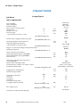
1
LYSAGHT W-DEK
®
Design Software
User's Guide
• Getting exceptional results from LYSAGHT
W-DEK for composite concrete slabs
• Acts as permanent formwork with minimal
propping and no stripping of formwork
• Works as composite slab saving on concrete
and reinforcement costs
• Formwork tables are optimised for steel frame
construction
Background
Warranties
LYSAGHT W-DEK is a new innovative profiled steel decking
which brings greater economy and design freedom to
building with composite concrete slabs. Our design engineers
scoured the globe to find the best “W”- profiles in the world.
After careful examination, our engineers incorporated the
best aspects of each profile into new LYSAGHT W-DEK. The
profile has been specifically developed for Australian high
tensile steels - which makes LYSAGHT w-dek one of the best
performing ‘W’ profiles in the world.
LYSAGHT W-DEK is a profiled zinc-coated high tensile steel
decking for use in the construction of composite floor slabs.
It has exceptional composite performance – no additional
reinforcement is required in most applications.
It can be used as formwork during construction and as a
reinforcement system in composite slabs.
Our increased understanding of composite slabs, together
with testing in our NATA-accredited laboratory and leading
Australian universities, has paid off with an optimised product,
which provides significant cost savings for projects.
LYSAGHT W-DEK has exceptional spanning characteristics
and spans up to 4.1 metres, reducing the need for supporting
structures.
The built-in properties of high tensile steel are maximised in
the design and fabrication of the deck profiles which result in
products with high strength-to-weight ratio. LYSAGHT W-DEK
is currently the most economical structural steel decking in
Australia for typical applications because it provides widest
cover per weight of steel.
The profiled ribs are 78mm in height, resulting in
LYSAGHT W-DEK having excellent concrete displacement
characteristics and minimal propping requirements. This
speeds up installation and makes the costs of delivery,
erection and structural framing significantly lower than for
other systems.
Our products are engineered to perform according to our
specifications only if they are installed according to the
recommendations in this manual and our publications.
Naturally, if a published warranty is offered for the product,
the warranty requires specifiers and installers to exercise
due care in how the products are applied and installed and
are subject to final use and proper installation. Owners
need to maintain the finished work..
Scope
This manual provides information on the design of formwork,
propping, composite slabs and design for fire and some
information for composite beams.
This manual is developed to the latest versions of the relevant
Australian Standards and Eurocodes.
Conditions of use
This publication contains technical information on the
following grades of LYSAGHT W-DEK:
• LYSAGHT W-DEK 0.75 mm thickness
• LYSAGHT W-DEK 1.00 mm thickness
Additionally, LYSAGHT W-DEK software allows you to get
quicker and more economical solutions with a range of
options. Call Steel Direct on 1800 641 417 to obtain additional
copies of the Design Manual and Software.
Where we recommend use of third party materials, ensure
you check the manufacturer's requirements. Diagrams are
used to explain the requirements of a particular product.
Adjacent construction elements of the building that would
normally be required in that particular situation are not always
shown. Accordingly aspects of a diagram not shown should
not be interpreted as meaning these construction or design
details are not required. You should check the relevant Codes
associated with the construction or design.
2
Preface
LYSAGHT W-DEK design software is a user-friendly Excelbased software for the design of composite concrete slabs
with LYSAGHT W-DEK structural decking.
It is suitable for steel frame construction.
LYSAGHT W-DEK design software is developed to Australian
Standards (AS) whenever possible, Eurocodes have been
used when certain design procedures are not available in
Australian Standards.
It is a tool developed with latest information to assist a
competent engineer with the most competent solution.
The software should be used to design composite slabs in
conjunction with the LYSAGHT W-DEK Design & Construction
Manual.
Disclaimer, warranties and limitation of liability
This publication is intended to be an aid for professional
engineers and is not a substitute for professional
judgement.
Terms and conditions of sale are available at local
BlueScope Lysaght sales offices.
Except to the extent to which liability may not lawfully be
excluded or limited, BlueScope Steel Limited will not be
under or incur any liability to you for any direct or indirect
loss or damage (including, without limitation, consequential
loss or damage such as loss of profit or anticipated profit,
loss of use, damage to goodwill and loss due to delay)
however caused (including, without limitation, breach of
contract, negligence and/or breach of statute), which you
may suffer or incur in connection with this publication.
LYSAGHT®, LYSAGHT W-DEK®, and galvaspan® are
trademarks of BlueScope Steel Limited A.B.N. 16 000 011
058
The LYSAGHT range of products is exclusively made by
BlueScope Steel Limited trading as BlueScope Lysaght.
All rights reserved. No part of this brochure may be
reproduced, stored in a retrieval system, or transmitted
in any form or by any means, electronic, mechanical,
recording or otherwise, without written permission of
BlueScope Steel Limited. ABN 16 000 011 058
© Copyright BlueScope Steel Limited February 9, 2010
Produced at BlueScope Lysaght R&D Department.
www.bluescopesteel.com
lysaght w-dek Design Software User Guide
2010
Contents
1. Introduction . . . . . . . . . . . . . . . . . . . . . . . . . . . . . . . . . . . . . . . . . . . . . 5
2. Getting started . . . . . . . . . . . . . . . . . . . . . . . . . . . . . . . . . . . . . . . . . . . 5
2.1 Computer requirements . . . . . . . . . . . . . . . . . . . . . . . . . . . . . . . . 5
2.2 Installing LYSAGHT W-DEK design software . . . . . . . . . . . . . 5
3. Software flowchart . . . . . . . . . . . . . . . . . . . . . . . . . . . . . . . . . . . . . . . 6
4. LYSAGHT W-DEK design software menu . . . . . . . . . . . . . . . . . . . . 7
5. Input dialogue box . . . . . . . . . . . . . . . . . . . . . . . . . . . . . . . . . . . . . . . 8
5.1 General . . . . . . . . . . . . . . . . . . . . . . . . . . . . . . . . . . . . . . . . . . . . . 8
5.2 Conditions of exposure . . . . . . . . . . . . . . . . . . . . . . . . . . . . . . . . 8
5.3 Spans . . . . . . . . . . . . . . . . . . . . . . . . . . . . . . . . . . . . . . . . . . . . . . 8
5.4 Composite slab deflection limits . . . . . . . . . . . . . . . . . . . . . . . 10
5.5 Crack control for flexure . . . . . . . . . . . . . . . . . . . . . . . . . . . . . 10
5.6 Creep and shrinkage factors . . . . . . . . . . . . . . . . . . . . . . . . . . 10
5.7 Degree of control of shrinkage and temperature effects . 11
5.8 Cover to negative bar . . . . . . . . . . . . . . . . . . . . . . . . . . . . . . . . 12
5.9 Fire Design . . . . . . . . . . . . . . . . . . . . . . . . . . . . . . . . . . . . . . . . . 12
5.10 Shrinkage reinforcement . . . . . . . . . . . . . . . . . . . . . . . . . . . . . 12
5.11 Loading parameters . . . . . . . . . . . . . . . . . . . . . . . . . . . . . . . . . 13
6. Design dialogue box . . . . . . . . . . . . . . . . . . . . . . . . . . . . . . . . . . . . . 15
6.1 General . . . . . . . . . . . . . . . . . . . . . . . . . . . . . . . . . . . . . . . . . . . . 15
6.2 Slab span . . . . . . . . . . . . . . . . . . . . . . . . . . . . . . . . . . . . . . . . . . 16
6.3 Formwork deflection limits . . . . . . . . . . . . . . . . . . . . . . . . . . . 16
6.4 Support width . . . . . . . . . . . . . . . . . . . . . . . . . . . . . . . . . . . . . . . 16
6.5 Live load . . . . . . . . . . . . . . . . . . . . . . . . . . . . . . . . . . . . . . . . . . . 17
6.6 Fire design . . . . . . . . . . . . . . . . . . . . . . . . . . . . . . . . . . . . . . . . . 17
7.Design/Check dialogue box . . . . . . . . . . . . . . . . . . . . . . . . . . . . . . 18
7.1 General . . . . . . . . . . . . . . . . . . . . . . . . . . . . . . . . . . . . . . . . . . . . 18
7.2 Slab thickness . . . . . . . . . . . . . . . . . . . . . . . . . . . . . . . . . . . . . . 18
8. Results window . . . . . . . . . . . . . . . . . . . . . . . . . . . . . . . . . . . . . . . . . 19
8.1 General . . . . . . . . . . . . . . . . . . . . . . . . . . . . . . . . . . . . . . . . . . . . 19
9. Warning messages . . . . . . . . . . . . . . . . . . . . . . . . . . . . . . . . . . . . . . 22
10. Sample report . . . . . . . . . . . . . . . . . . . . . . . . . . . . . . . . . . . . . . . . . . 24
11. Software Disc . . . . . . . . . . . . . . . . . . . . . . . . . . . . . . . . . . . . . . . . . 27
lysaght w-dek Design Software User Guide
2010
3
1. Introduction
This User’s Manual is designed to provide you with basic
familiarity about LYSAGHT W-DEK design software to
enable you to quickly understand and start using this
powerful tool. The software is able to perform major tasks
normally performed at a structural consultant’s office. Use
LYSAGHT W-DEK Design and Construction Manual with
its set of tables. When input parameters are different from
those listed for tables or the user wants to check several
different options, the software will help with that.
The software offers following additional design options as
compared to tables:
• Two major design options: Design and Design/
Check. The first option will perform design with the
minimum possible slab thickness; the second one
will check the chosen slab thickness and design the
rest of the parameters.
• Selection of exposure classifications (A1, A2, B1
and B2)
•
25, 32 and 40 MPa concrete grades
•
Superimposed dead load other than 1 kPa
•
Other than office types of imposed loads
• Composite slab deflection limits L/250 for total loads
and L/500 for incremental deflection
•
Equal spans
• For negative, positive fire and shrinkage
reinforcement,
use D500N, D500L or 400Y
• User specified bar diameter
•
Specified number of continuous spans (two-span,
three-span etc.).
• Degree of control for shrinkage and temperature
effects
• All fire rating periods: 30, 60, 90, 120, 180 and 240
min.
• Variable loads due to weight of stacked materials
during construction stage.
• Design with relaxed crack control requirements for
flexure
•
Support width
• User specified concrete cover
!
This warning symbol means the user shall take care
before proceeding further.
HELP
This symbol means that there is more information on this
topic in other chapters.
A S
This symbol means that the user shall refer to the relevant
Australian Standard or Eurocode for more information.
This symbol means that this is important information.
The user shall ensure they understand before proceeding.
The software is developed as a powerful tool to minimise
time and efforts necessary by a consulting engineer to
complete the job. However, it is essential for the user to
have:
•
Good knowledge of structural engineering
•
Familiarity with design of composite concrete slabs
• Sound knowledge of local regulations and load
requirements
For more information and technical support, contact Steel
Direct on 1800 641 417.
4
lysaght w-dek Design Software User Guide
2010
2. Getting Started
2.1. Computer Requirements
To run LYSAGHT W-DEK design software your computer
must have Microsoft Excel 2000 or a later version, on
Windows platform.
2.2 Installing LYSAGHT W-DEK Design Software
The LYSAGHT W-DEK design software CD is fixed on the
inside back cover of this Guide.
It contains LYSAGHT W-DEK design software Excel file,
User’s Guide and Design and Construction Manual in .pdf
format.
On your hard disc, create a directory (folder) called
LYSAGHT W-DEK design software, and place the files from
CD into the folder. Run the software, in the usual way, by
double-clicking on the icons.
Ensure you enable Macros before proceeding with
LYSAGHT W-DEK design software. The security settings for
Excel shall be set to medium level when applicable.
lysaght w-dek Design Software User Guide
2010
5
a
tp
me
ra
Specify parameters in
Input dialogue box
for End Span
s
ter
Rev
is e
inp
ut
pa
ra
er
et
Re
vis
e
m
in
pu
3. Software Flowchart for the Design of Continuous Spans
s
NO
Slab thickness known?
Specify parameters
in Design dialogue box
and click Design
YES
Specify parameters
in Design/Check
dialogue box and click
Design/Check
NO
NO
The design output is
satisfactory (passed)
and economical?
The design output is
satisfactory (passed)
and economical?
YES
YES
Repeat above procedure
for one Interior Span
(Equal Spans)
or several Interior Spans.
Less than five spans
NO
YES
Repeat above procedure
for one Interior Span with
thicknesses required for
End Span using
Design/Check
dialogue box.
END
6
Repeat above procedure for
Interior Spans using either
of these two options
– the same thickness as for End Span,
using Design/Check dialogue box
– minimum thickness using
Design dialogue box
END
lysaght w-dek Design Software User Guide
END
2010
4. LYSAGHT W-DEK Software Menu
LYSAGHT W-DEK design software Menu options are built
into Excel Menu on the top of the screen.
Excel Menu may look different from what is shown below.
There are three additional Menu options:
•
Analyse (LYSAGHT w)
•
Print (LYSAGHT w)
•
Report (LYSAGHT w)
Figure 1
Analyse Menu
HELP
Figure 2
Print (LYSAGHT w) Menu
Analyse (LYSAGHT w) Menu has three submenu options:
•
Input
•
Design
•
Design/Check
These options will be described in details in further
chapters.
When the software is opened, the Input dialogue box will
appear on the screen automatically (see cover page). For
the second and consecutive runs, the user shall access the
Input dialogue box through Menu.
Print (LYSAGHT w) Menu allows the user to print Output/
Input information or Report.
HELP
Report (LYSAGHT w) Menu will generate detailed design
report which is described in more details in Chapter 10.
Figure 3
Report (LYSAGHT w) Menu
It shall be noted that LYSAGHT w Menu options are available
only when LYSAGHT W-DEK design software Excel file is
activated.
lysaght w-dek Design Software User Guide
2010
7
5. Input Dialogue Box
5.1 General
Input dialogue box is designed for quick and easy data entry.
The user shall normally just choose one of available options.
If required input information is missed or incorrect, the
warning message would appear on the screen.
5.2 Conditions of Exposure
Figure 4
Exposure classification
A S
The Exposure Classification shall be specified as required
by AS3600-2001 Clause 4.3
5.3 Spans
Figure 5
Spans
Figure 6
Continuous Spans
The user may specify Single Spans or Continuous Spans
depending on the project.
Increased slab thickness may be required in many
instances when continuous slabs are designed as a series
of simply supported spans.
If the span is a Continuous one, the user may run the
software several times: for End Spans and Interior Spans
separately. If the continuous span is a Two spans then
there is no option for Interior Spans, both spans are end
ones. It shall be noted that Continuous Spans refer here to
composite concrete slabs only, LYSAGHT W-DEK formwork
spans are specified in Design and Design/Check dialogue
boxes.
End Spans and Interior Spans may be designed with a
different thickness to get the most economical design.
However, The first Interior Span from the end support shall
always have the same thickness as the End Span.
8
lysaght w-dek Design Software User Guide
!
2010
When the slab has less than five spans the user shall
run End Spans first using Design Menu option to get the
minimum possible slab thickness.
Then Interior Spans shall be designed with the slab
thickness obtained for End Spans using Design/Check
Menu option.
When the slab has five or more spans, the thickness
of Interior Spans other than first Interior Span may be
specified independently from End Spans.
See flowchart on page 6.
End and Interior Spans
are the same thickness
LYSAGHT W-DEK
End span negative
reinforcement
Interior span negative
reinforcement
End Span
Interior Span
Figure 7
Spans
Slab thickness of
Interior Spans
may be reduced
Interior span reinforcement
Max as required for adjacent spans
LYSAGHT W-DEK
End Span
First Interior Span
Interior Span
Figure 8
Spans
Figure 9
Ratio of Spans
!
The user may specify all spans as equal spans and with
maximum Ratio of longer to shorter adjacent span of 1.2.
The software options for irregular lay outs with higher
ratios of adjacent spans is not currently available, contact
BlueScope Lysaght R&D for more information.
lysaght w-dek Design Software User Guide
2010
9
5.4 Composite Slab Deflection Limits
Figure 10
Composite slab deflection limits
The software is developed for Span/250 Composite slab
deflection
limits due to total load and two options for deflections
limits due to imposed loads:
•Span/500 is recommended by AS3600-2001 TABLE
2.4.2 for concrete slabs which support brittle
partitions like masonry walls, glass doors.
•
No limits for slabs not supporting brittle partitions
A S
5.5 Crack Control for Flexure
Figure 11
Crack control for flexure
Not required option may be used for areas of slabs fully
enclosed within a building except for a brief period of
weather exposure during construction and where it is
assessed that wider cracks can be tolerated - according
to AS3600-2001 Clause 9.4.1. This option will design
reinforcement as required for relaxed crack control. Items 9
(i) and (iii) of Clause 9.4.1
A S
5.6 Degree of Control of Shrinkage and Temperature Effects
Figure 12
Shrinkage control
Refer to AS3600-2001 Clause 9.4.3 for shrinkage control
requirements.
A S
Figure 13
Environment for shrinkage strains
10
lysaght w-dek Design Software User Guide
2010
It shall be noted that arid (interior) environment will result
in higher shrinkage strains, which in turn may result in
deeper slabs.
5.7 Properties of Materials
Figure 14
Concrete grades
The minimum Concrete grade possible depends on
Exposure Classification.
B2 classification will require minimum concrete grade of
40MPa.
Figure 15
Negative, positive and fire reinforcement
grade
Figure 16
Negative bar sizes
Positive and fire bar sizes
Figure 17
LYSAGHT W-DEK BMT (base material
thickness)
lysaght w-dek Design Software User Guide
2010
11
The software may design composite slabs using : 0.75 BMT
or 1.0 BMT sheets. The user may try 0.75 BMT for the first
run. If the design is not economical (props are necessary),
next run with increased BMT may be necessary. Contact
Steel Direct to design slabs with 1.2 BMT LYSAGHT W-DEK.
5.8 Cover to Negative Bar
Figure 18
Cover to negative bar
Users shall specify appropriate covers to ensure that
the concrete can be satisfactorily placed and compacted
around reinforcement in accordance with the requirements
of AS3600-2001, Clause 19.1.3 and 4.10.
A S
5.9 Fire Design
!
Figure 19
Fire Design
At this stage the user shall specify if the Design for fire is
required or not.
The requirements for Fire Reinforcement and its location
within the composite concrete slab is given in Chapter 8.
HELP
5.10 Shrinkage Reinforcement
This reinforcement is necessary to control cracking due to
shrinkage and temperature effects in transverse direction.
Shrinkage reinforcement can be specified as mesh or bars.
Figure 20
Shrinkage reinforcement
Users can specify the diameter of reinforcement and
spacing
for longitudinal bars if the reinforcement grade is D500N.
The detailed definition of Shrinkage reinforcement and its
location within the composite concrete slab is given in
AS3600-2001 Clause 9.4.3.
If rectangular mesh (RL) is specified it shall be
oriented such as more steel is spanning in transverse
(perpendicular to sheeting) direction.
12
A S
lysaght w-dek Design Software User Guide
2010
5.11 Loading Parameters
Figure 21
Superimposed dead load
Superimposed dead load (G) is a load of permanent nature
in addition to self weight of composite concrete slabs.
Figure 22
ψs load factor
A S
ψs and ψl are factors for Live (Imposed) Loads. Live Load
itself shall be entered in Design or Design/Check dialogue
boxes which are described in next Chapters.
Refer to AS1170.0 : 2002 for more information.
lysaght w-dek Design Software User Guide
2010
13
Figure 23
Stacked materials
This is the weight of Storage loads as specified in
AS3610-1995, Clause 3.2.5. during construction stage
before concrete is placed.
The value of the Storage Load is 4kPa. A 1kPa option is
available.
If load is less than 4kPa is specified, it shall be clearly
shown on formwork documentation and controlled on
construction site.
14
A S
lysaght w-dek Design Software User Guide
2010
6. Design Dialogue Box
6.1 General
When the user entered all necessary parameters in the
Input dialogue box, the next step would be to click Design
or Design/Check button at the bottom of the Input dialogue
box. This will open one or another dialogue box. The
Design option is used when the user wants to design the
slab to the very minimum slab thickness. Design/Check
option shall be used when the possible slab thickness is
known. (User controlled - See flowchart on page 6.)
Figure 24
Design dialogue box
lysaght w-dek Design Software User Guide
2010
15
6.2 Slab Span
Figure 25
Slab span
The user shall type in the span length. It shall be centre to
centre span, see Chapter 8 of this Guide for more details.
The range of possible spans is from 1.8 to 6m.
HELP
6.3 Formwork Deflection Limits
Figure 26
Formwork deflection limits
Formwork deflection limits shall be specified as required
by
AS3610:1995 and AS2327.1. Span/240 (visual quality
important) deflection limit is recommended for slabs in
which good general alignment is required. It is suitable for
a Class 3 or 4 surface finish.
L/130 (visual quality not important) deflection limit is
suitable for Class 5 surface finish.
A S
6.4 Support Width
Figure 27
Support width
This is a width of a supporting structure – steel beams. It is
important to enter correct value – it may result in smaller
BMT of the LYSAGHT W-DEK formwork.
16
lysaght w-dek Design Software User Guide
2010
6.5 Live Load
Figure 28
Live load
A S
Live Load (Q) shall be specified as required by AS1170.1 - 2002.
6.6 Fire Design
Figure 29
Fire design
A S
The user may specify Fire-resistance periods of 30, 60,
90, 120, 180 and 240 minutes as defined by AS3600-2001
Section 5.0
Figure 30
Fire reinforcement option.
lysaght w-dek Design Software User Guide
2010
17
7. Design/Check Dialogue Box
7.1 General
When the user entered all necessary parameters in the
Input dialogue box, the next step would be to click Design
or Design/Check button at the bottom of the Input dialogue
box. This will open one or another dialogue box. The
Design option is used when the user wants to design the
slab to the very minimum slab thickness. Design/Check
option shall be used when the slab thickness is known
(user controlled). It may be in a case when the architect
specified the slab thickness for other than structural
reasons or Interior spans shall be designed to the slab
thickness as required for End spans – see Chapter 5.3 of
this Guide and the flowchart.
HELP
Figure 31
Design & Design/Check Options
This Dialogue box has the same options as Design dialogue
box with an addition of Slab thickness option.
Figure 32
Design/Check dialogue box
7.2 Slab Thickness
Figure 33
Slab thickness
The slab thickness may vary from 130 to 250 mm. The
user shall type in the necessary slab thicknesses. Slabs
thicknesses of more than 250 mm are considered as not
practical. LYSAGHT’s Steel Direct shall be contacted to
design slabs with more than 250 mm thickness. (Contact
details are on back cover.)
18
lysaght w-dek Design Software User Guide
2010
8. Results Window
8.1 General
The Results window will appear on the screen
automatically when the user clicks the Design or Design/
Check buttons on the relevant Dialogue box. Alternatively,
the window may be opened by clicking on the Results
worksheet at the bottom of the Excel window.
The window shows the design summary (Design Output)
and the list of entered parameters in Input, Design or
Design/Check dialogue boxes (Input parameters).
Figure 34
Results window
lysaght w-dek Design Software User Guide
2010
19
The reinforcement types in the Design Output table is
explained in the following Figures:
Negative (top tensile)
and Fire (Fire detail 1)
reinforcement
Depth of
composite
slab
Concrete
cover
140
140
LYSAGHT W-DEK
Positive tensile
and Fire (Fire detail 2)
reinforcement
Mesh
reinforcement
Transverse wire of
mesh reinforcement
Permissible zone for fire
and top tensile (negative)
reinforcement
Figure 35
Wall
Wall
Negative (top tensile) and
Fire (Fire detail 1)
reinforcement
0.3Ln
100mm minimum
Slab cross section
0.3Ln
Fire (Fire detail 1)
reinforcement
Concrete
Cover
Concrete slab
0.3Ln
Ln
Ln
L (span)
L (span)
Restraint at
end support
by mass of wall
Temporary
prop
Little or no
restraint at
end support
Continuous over
interior support
Figure 36
LYSAGHT W-DEK Pattern 1 for conventional (standard) reinforcement
1. Negative (top tensile) reinforcement shall be placed
within a permissible zone for fire rated slabs.
Negative reinforcement may be placed outside
permissible zone if design for fire is not required.
If it is necessary to place negative reinforcement outside
the permissible zone for fire rated slabs, the design is
possible through consultation with Customer Support
which is accessed via Steel Direct 1800 641 417.
2. Positive tensile reinforcement is given as extra area to
fire reinforcement
(Detail 2 ) and may be placed outside the permissible
zone. Alternatively, fire bars (Detail 2) may be specified
with increased diameter to satisfy requirements for
positive tensile reinforcement.
3. At least one bar per rib is recommended for all types of
reinforcement except mesh.
20
Wall
Minimum 50mm
Minimum 70mm
Wall
Positive tensile and
Fire (Fire detail 2)
reinforcement
LYSAGHT W-DEK
lysaght w-dek Design Software User Guide
2010
100mm minimum
0.3Ln
Wall
Wall
Negative (top tensile) and
Fire (Fire detail 1)
reinforcement
0.3Ln
Negative (top tensile) and
Fire (Fire detail 1)
reinforcement
Concrete
Cover
Concrete slab
Minimum 50mm
bearing length
Ln
Temporary
prop
Minimum 70mm
bearing length
Wall
Positive tensile and
Fire (Fire detail 2)
reinforcement
LYSAGHT W-DEK
Wall
0.3Ln
Ln
L (span)
L (span)
Restraint at
end support
by mass of wall
Little or no
restraint at
end support
Continuous over
interior support
Figure 37
Pattern 2 of top tensile (negative)
reinforcement
!
Pattern 2 for negative reinforcement shall be used when
Live Load exceeds twice the dead load.
Every third bar of negative reinforcement at support shall
continue all over the span (for Pattern 2 only)
Fire shall be designed for one option only - (Fire detail 1 or
Fire detail 2.)
lysaght w-dek Design Software User Guide
2010
21
9. Warning Messages
Slab can not be designed to specified thickness
This message means that the minimum possible slab
thickness shall be more than specified by the user using
Design/Check option. The user may:
• Increase slab thickness specified using Design/Check
option
• Reduce minimum required slab thickness by:
• Increasing concrete grade
• Decreasing Tensile and Compression reinforcement
bar size
• Increasing slab deflection limit to L/250
All input parameters shall be checked if adequate.
Slab thickness shall be within 130mm to 250mm
This means that slab thickness entered is not correct.
250 mm is considered as the maximum practical slab thickness.
Contact Steel Direct if you still want to design deeper slabs.
This means that the slab span entered is outside allowed limits.
Tensile & compression reinforcement bar size have not been entered
Self explanatory.
22
lysaght w-dek Design Software User Guide
2010
Fire reinforcement bar size has not been entered
Self explanatory.
Specify correct number of spans for continuous slabs
That message may appear when the user designs first
continuous span as an end double span and then tries to
design interior span (as double span). The interior span shall
be specified for continuous slabs with three or more spans.
!
1 kPa stacked materials Load shall be clearly
specified on formwork documentation. Continue?
The user may chose Yes and continue with the
design. However, 1 kPa load shall be clearly
specified on design documentation and controlled
on a construction site.
The transverse bar size has not been entered.
Self explanatory.
lysaght w-dek Design Software User Guide
2010
23
10. Report - Sample Pages
LYSAGHT W-DEK
Lysaght Typical
Job Name:
INPUT PARAMETERS:
Type of building
Span configuration
Continuous spans
Ratio of shorter to longer spans
Slab thickness
Density of concrete:
Concrete grade
Concrete slab span, centre to centre
Exposure classification
Reinforcement (negative, positive, fire) grade
Reinforcing (positive, fire) bar diameter
Reinforcing negative bar diameter
Deflection limits of composite slabs
Dc
rg
mm
kg/m3
L
mm
(AS 3600-2001, Table 4.3)
D500N
(AS 36000-2001, Table 6.2.1)
mm
mm
Moderate
D500N
mm
mm
mm
Lysaght W base metal thickness
Permanent support width
Superimposed dead load
Live Load
Load factor
Load factor
Construction loads due to
to weight of stacked materials
Fire resistance level
NO
Arid (interior)
Three or more spans
Visual quality not important
(AS 2327.1-2003, Clause C2)
t
mm
mm
0.75
100
kPa
kPa
1
4
0.7
0.4
M
(AS 3610-1995, Clause 4.4)
kPa
1
FRL
(Building Codes of Australia)
min
120 min
Gsup
Q
ys
yl
Load factor for imposed loads during fire
24
N12
N12
300
20
(AS 3600-2001, Table 4.10.3.2)
Slab acting compositely with steel beams or
used as diaphragm
Environment for shrinkage strains
Formwork sheets continue over number of spans
Formwork deflection limit
12
12
Total <L/250
(AS 3600-2001, Table 2.4.2)
Degree of control for shrinkage and temperature effects
Shrinkage mesh grade
(AS 3600-2001, Table 6.2.1)
Mesh or transverse bar diameter
Mesh longitudinal bar diameter (if D500N)
Mesh longitudinal bar spacing (if D500N)
Concrete cover
Steel frames
End Spans
Three spans
up to 1.2
165
2400
32MPa
3100
A1
lysaght w-dek Design Software User Guide
Fire Detail 1
2010
Formwork design
Number of temporary props
0
PROPERTIES OF LYSAGHT W:
Moment capacity in positive bending
Moment capacity in negative bending
(used in partial plastic analysis)
Shear (web crippling) capacity
Effective Second Moment of Area
(for serviceability calcs.)
f M +u
f M -u
kNm/m
kNm/m
6.61
3.2
f Vu
kN/m
23.0
mm4/m
775000.0
MPa
550.0
Ieff,ser
(AS/NZS 4600:1996, Section 6)
fy
(AS/NZS 4600:1996, Table 1.5)
Yield stress
Young's modulus of elasticity
200000
(AS/NZS 4600:1996, Table 1.4)
DESIGN LOADS:
Self weight of sheeting
Self weight of concrete and reinforcement
Concentrated Live Load
Concentrated Live Load UDL equivalent
Load from stacked materials
Live Load
Concentrated point load
Self weight of reinforcement
Gsh
Gc
Qc
kPa
kPa
kPa
kPa
kPa
kPa
0.09
3.47
3.0
2.31
1.0
1.0
kN
kPa
2.0
0.1
F dla = 1.25*G sh +1.5*Q uv +1.5Q M
F dlb = 1.25*G sh +1.5*Q r+Qp
kPa
3.1
F dlla = 1.25*G sh +1.25G c +1.5*Q uv
F dllb = 1.25*G sh +1.25G c +Qc
kPa
5.9
6.8
F def = Gsh +G c
(AS 3610-1995, Table 4.5.1)
kPa
3.6
M*
kNm/m
F* v
kN/m
6.53
OK
10.4
OK
Qc,equiv
M
Quv
(AS 3610-1995, Clause 4.4)
Qp
Qr
(AS 2327.1-2003, Clause F2)
LOAD COMBINATIONS:
Strength:
Stage 1(before placing concrete):
Stage 2(after placing concrete):
Serviceability:
DESIGN FOR STRENGTH:
Maximum positive bending moment
M*<f M +u
Maximum shear force
F* v <f V u
Combined bending and shear
Not applicable for partial plastic analysis
DESIGN FOR SERVICEABILITY:
Deflections
Deflection limits
Dtot
Dtot,max
Dtot<MIN(Dtot,max )
lysaght w-dek Design Software User Guide
mm
mm
14.6
23.8
OK
2010
25
Composite slab design
MATERIAL PROPERTIES AND SLAB GEOMETRY:
fy
Yield stress of mesh reinforcement
fy,sh
Lysaght W sheeting yield stress
fy,bar
Yield stress of reinforcing bars
τu,Rd
Longitudinal shear capacity
(prEN 1994-1-1, Clause B.3.6)
Ratio of compressed stress block
γ
ksc
Long term shrinkage and creep factor
(AS 3600-2001, Clause 8.5.3.3)
Modulus of elasticity of concrete
Ec
(AS 3600-2001, Clause 6.1.2)
fcs
Shrinkage induced tensile stress
(AS 3600-2001, Clause 8.5.3.1)
hr
Depth of Lysaght W
ysh,eff
Distance from centroidal axis of Lysaght W
to extreme fibre in tension
ep
Distance from plastic neutral axis of Lysaght W
to extreme fibre in tension
(prEN 1994-1-1, Clause 9.7.2)
Ape
Effective cross-sectional area of Lysaght W
(prEN 1994-1-1, Clause 9.7.2)
LOADING:
Concrete slab self weight
Superimposed Dead Load
Live Load
G
(concrete, reinforcement and sheeting)
Gsup
Q
LOAD COMBINATIONS:
Strength:
1) Fu=1.5*G (the rest of spans)
(AS 1170.1-1989)
(AS 3600-2001, Clause 7.6.4)
2) Fu=1.5*G (the rest of spans)
(EN 1990, Section 6)
Deflections:
26
Total propped F s,tp = (1+k sc) G + (ψs + k l)Qψ
Total unpropped F s,tup = (1+k sc) Gsup + ( cs ψl)Q + k
Incremental propped F = ks,ipsc G + (ψs ψ l)Q+ kcs
Incremental unpropped F = k s,iup sc Gsup s + kcs ψ + (ψl)Q
(AS 3600-2001, Clause 8.5)
lysaght w-dek Design Software User Guide
MPa
MPa
MPa
MPa
500
550
500
115
0.822
2
MPa
28600
MPa
0.4113
mm
mm
78
32
mm
78
mm2
711
kPa
3.40
kPa
kPa
1
4
kPa
kPa
11.51
5.51
kPa
kPa
11.95
5.95
kPa
kPa
kPa
kPa
N/A
9.00
N/A
8.00
2010
11. Software Disc
lysaght w-dek Design Software User Guide
2010
27
Product Descriptions
All descriptions, specifications, illustrations, drawings, data, dimensions and weights contained this
catalogue, all technical literature and websites containing information from BlueScope Lysaght are
approximations only.
They are intended by BlueScope Lysaght to be a general description for information and identification
purposes and do not create a sale by description. BlueScope Lysaght reserves the right at any time to:
(a) supply Goods with such minor modifications from its drawings and specifications as it sees fit; and
(b) alter specifications shown in its promotional literature to reflect changes made after the date of such
publication.
Disclaimer, warranties and limitation of liability
This publication is intended to be an aid for all trades and professionals involved with specifying and installing
LYSAGHT products and not to be a substitute for professional judgement.
Terms and conditions of sale available at local BlueScope Lysaght sales offices.
Except to the extent to which liability may not lawfully be excluded or limited, BlueScope Steel Limited will
not be under or incur any liability to you for any direct or indirect loss or damage (including, without limitation,
consequential loss or damage such as loss of profit or anticipated profit, loss of use, damage to goodwill and
loss due to delay) however caused (including, without limitation, breach of contract, negligence and/or breach
of statute), which you may suffer or incur in connection with this publication.
© Copyright BlueScope Steel Limited 9 February 2010
For technical information contact [email protected] or call 1800641417
www.lysaght.com
Please check the latest information which is always available on our website.
LYSAGHT and Lysaght W-dek are registered trademarks of BlueScope Steel Limited, ABN 16 000 011 058.
The LYSAGHT ® range of products is made by BlueScope Steel Limited trading as BlueScope Lysaght.
Printed by BMP 1M 02/10