1
For use with Q.E.D. control panels only.
Previous Menu
N6484V3 3/96
5827BD and 5827BDE
WIRELESS BI-DIRECTIONAL KEYPADS
Used with 5800TM Transmitter Module
INSTALLATION INSTRUCTIONS and OPERATING GUIDE
Unless otherwise indicated, all information in this manual is applicable to both the 5827BD and 5827BDE
GENERAL INFORMATION
T he 5827BD and 5827BDE Wireless Bi-directional Keypads are
designed to be used in conjunction with a 5800TM Transmitter
Module. Additional 5827BDs (any quantity) may be used in
conjunction with the same 5800TM; however, no more than eight
5827BDEs may be used. The 5800TM is compatible with any
control panel that is also equipped with a 4281 type (5700 System)
or 5881 type (5800 System) RF receiver.
Note: The 5827BDE is an enhanced version of the 5827BD and
employs AdemcoÕs new SignalSentryª technology, which
can provide high security wireless transmissions when used
in conjunction with the 5881EH RF receiver.
The 5827BD and 5827BDE can operate the protection system
similarly to other wireless keypads, via keypad buttons. In addition,
three LEDs (Red, Green, and Yellow) and a piezoelectric sounder
can indicate status information relative to:
System arming/trouble/emergency, RF transmission/confirmation,
and 5827BD/5827BDE programming and power.
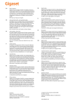
The keypad configuration is similar to that of standard keypads. The
[ ★ ] key, however, is also the [ON/STAT] (power-up and system
status inquiry) key instead of a "READY" key, as it is on other
keypads (see OPERATION). There are three panic keys: A, B, and
C, comparable to the individual keys (or panic key pairs of [1] & [★ ],
[ ★ ] & [#], and [3] & [#] respectively) on other keypads.
The 5827BD and 5827BDE keypads, if so-programmed, also
feature "Quick Key" operation, which allows use of the [#] key
instead of entry of the security code when performing functions.
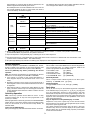
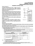
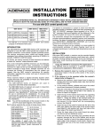
ANTENNA
(OPTIONAL)
SOUNDER
LEDS
GREEN
YELLOW
RED
ARM
AFFIX
PANIC KEY
LABELS HERE
AY
F
OF
PANIC KEYS
AW
1
UM
TE
4
M
5
T
AN
ST
2
ST
M
I
AX
IN
5800TM Transmitter Module
For every installation of one or more 5827BD or 5827BDE Wireless
Keypads, one 5800TM is required. The 5800TM complements the
RF receiver in that it transmits the information to be displayed on, or
sounded by, the 5827BD or 5827BDE. No modification to the
control is necessary. The 5800TM connects directly to the control's
wired keypad connection points, as described later.
SEND/RCV
READY
C (3/#)
B (★/#)
A (1/★)
DE
CO
7
8
AY
ST
3
S
AS
P
BY
6
E
IM
CH
9
T
TA
/S
ON
*
0
#
POWER-UP KEY
5827BD
5827BD & 5827BDE INSTALLATION
The 5827BD and 5827BDE are designed to be portable, for use
throughout the protected premises. If desired, a wireless keypad
may be stored on its accompanying mounting bracket (easily
installable via two countersunk mounting holes). Keyhole slots on
the rear of the keypad slip onto two hooks on the mounting bracket,
allowing the keypad to be easily removed when desired .
When operating, or selecting a location for storing the wireless
keypad, observe the same precautions as used for locating the
wireless system's other transmitters (see the control panel's
instruction manual). For example, operating the keypad on or near
large metal objects may decrease range and/or block
transmissions.
1. Install the keypad's 9-volt Alkaline battery. S lide off the
battery compartment cover at the rear of the keypad and insert
the battery. Observe polarity! Then replace the cover.
2. Program the keypad's memory as indicated next.
Programming the Wireless Keypad
a. Power up the keypad by depressing the [★ ] key. The
yellow LED will blink.
If the keypad was previously programmed, the system
status may also be annunciated (see Power-up and
System Status Inquiry on the next page).
b. Enter the keypad programming mode by
depressing both the [1] and [3] keys at the same time
for 3 seconds.
Alternate blinking of the red and green LEDs confirms
that the unit is in the keypad programming mode.
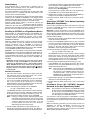
c. Program the desired functions, in the order given
in the Programming table that follows. Note that
every sequence starts with a [★ ] and ends with a [#].
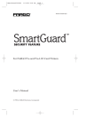
PROGRAMMING TABLE FOR 5827BD AND 5827BDE*
* Note: A section later in this manual provides the necessary information for enrolling the 5827BDE as a SignalSentry
(high security) device. See Enrolling the 5827BDE as a SignalSentry Device. However, the 5827BDE must first
be set up and tested in its normal operating mode, as indicated in the following sections.
FUNCTION
ENTER
[★ ] + [8] + [4-Digit Master Code] + [#]
1. To Enter YOUR System's 4-Digit Master CodeÊ:
Operation †
2. To Enable Quick Key
(Arm, Disarm, & Chime):
or
To Enable Quick Key Operation † (Arm & Chime, but not Disarm)
[★ ] + [1] + [4-Digit Master Code] + [#]
3. To Enter YOUR 5700/5800 System's House ID:
(e.g., 06) selected from 01Ð31
[★ ] + [9] + [0] + [6] + [#]
4. To Enter RF System Used, 5700 system (4281 type RF receiver):
or
To Enter RF System Used, 5800 system (5881 type RF receiver):
[★ ] + [5] + [7] + [#]
5. To Exit the keypad programming mode:
[★ ] + [#]
[★ ] + [2] + [4-Digit Master Code] + [#]
[★ ] + [5] + [8] + [#]
†
Enabling ÒQuick KeyÓ may be skipped if this is not desired.
Notes: 1. Upon the detection of each closing '#', a confirmation sound is generated:
a) Following a valid entry, a triple beep. ÊÊÊ b) Following an erroneous entry, a single, long (2 sec) beep.
2. The keypad can be re-programmed at any time.
3. Each time the keypad programming mode is entered, Quick Key operation is disabled and must be re-enabled, if so
ÊÊÊÊÊdesired.
3. For addressable 2-partitioned systems, i.e.,Vista-40, cut Red
for partition 1 or White for partition 2. No additional programming is necessary.
For a Non-Addressable System:
Do not cut any jumpers. No programming is required.
3. Affix the appropriate panic key label to the space below
any panic key that is active, according to the function that
has been programmed for it in the control. A sheet of labels
accompanies the wireless keypad.
Note: ÊÊNot all of the three panic keys may be active for the
system with which the keypad is used. This depends on the
type of control used and its programming. Refer to the
control's installation manual.
4. Connect the provided antenna, if necessary, by screwing it
into its threaded connector at the top of the wireless keypad.
The keypad has an internal antenna, and in many installations
the system will operate adequately with this antenna alone.
However, for large installations where longer range may be
required, it may be necessary to add the external antenna.
5800TM Transmitter Module Wiring Connections
Connect the 5800TM to the control panel's keypad connection
points, using the supplied connector with flying leads. Wire colors
and functions match those for wired keypads:
RED: +12VDC
BLACK: Ground
GREEN:
Data to Control Panel
YELLOW: Data from Control Panel
BLUE: Not used
5800TM Transmitter Module Installation
Installation instructions accompany the 5800TM, but are given
here as well, for your convenience.
Observe the same precautions in selecting a location for the
5800TM as for the system's RF receiver, to ensure good
transmission and reception. The 5800TM must be located next to
the system's receiver (between one and two feet from the
receiver’s antennas). Do not install the 5800TM within the
system control panel's cabinet. Mount it remotely, on its
accompanying mounting bracket. The bracket is identical to the
one that accompanies the wireless keypad and may be mounted
in the same way.
OPERATION
Power-up and System Status Inquiry
Touching the [ ★ ] ([ON/STAT]) key powers up the wireless
keypad, and sends an inquiry to the 5800TM, requesting the
system status to be annunciated (see table on next page).
Subsequent depressions of the same key will initiate additional
inquiries.
Notes:
1. Upon power-up (by depression of the [ON/STAT] key, the
yellow LED will blink. The yellow LED will be lit during RF
communication, indicating transmission is in progress or
reception has just been completed. If a low battery condition
exists in the wireless keypad, it will be displayed on wired
keypads as zone “00.” (or “64” on some controls).
2. At any time (following a power-up), the depression of any key
and its acceptance by the keypad will be indicated by a blink
of the yellow LED, and a brief key actuation "blip" will be
heard. (As explained later, a panic key has to be continuously
depressed for at least 2 seconds in order to power-up and/or
be accepted by the system.)
3. A long (2 second) beep occurring within 4 seconds after
power-up or following the last key depression (of a com mand
or an inquiry) indicates lack of response from the control (via
the 5800TM). Press the [ON/STAT] key again (or move to a
new location and re-key your command).
5800TM Transmitter Module Programming
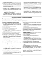
For an Addressable System:
1. Select one of the following addresses for the 5800TM by
removing its cover and cutting the appropriate jumper(s) on its
circuit board, as follows:
FOR ADDRESS
CUT JUMPER(S)
28
RED (W1)
29
WHITE (W2)
30
BOTH
2. Program the control panel, by designating the address
(selected above) as a wired keypad in the systemÕs ÒDevice
ProgrammingÓ section.
2
Approximately 10 seconds after the last key depression, the
wireless keypad will automatically power down.
No subsequent LED or sound indications will occur until the
unit is again powered up (thus, in chime mode, the chime is
not annunciated by the wireless keypad).
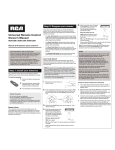
The following table shows the various status indications that can
occur during the time that the unit is powered up.
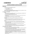
SYSTEM STATUS INDICATIONS for 5827BD/5827BDE
LED
LED
CONDITION
ON
STEADILY
ÊÊÊÊÊÊÊÊÊÊÊÊÊÊÊÊÊ SYSTEM STATUS ➀
KEYPAD'S SOUNDER
2 BEEPS ➁
3 BEEPS ➁
ARMED AWAY OR MAXIMUM
ARMED STAY OR INSTANT
PULSED BEEPING ➂
ARMED, FIRE ALARM IN PROGRESS, OR MEMORY
OF IT IS PRESENT
ARMED, BURGLARY IN PROGRESS, OR MEMORY
OF IT IS PRESENT
RED
(ARM)
BLINKING
STEADY SOUND ➂
SILENT
GREEN
ON STEADILY
(READY)
BLINKING
1 BEEP ➁
SILENT
BLINK
BRIEF "BLIP"
BLINK
SILENT
YELLOW➃
DISARMED, BUT NOT YET CLEARED OF ALARM
MEMORY HISTORY (BURGLARY OR FIRE)
DISARMED, READY TO ARM
DISARMED, NOT READY TO ARM
KEY DEPRESSION AFTER POWER-UP
UPON 5827BD/5827BDE POWER-UP
(SEND/RCV)
RF TRANSMISSION IN PROGRESS OR RECEPTION
JUST COMPLETED
and, as explained in the INSTALLATION section for the wireless keypad:
RED &
GREEN
ALTERNATELY
BLINKING
SILENT
5827BD/5827BDE IS IN KEYPAD PROGRAMMING
MODE
➀ With 4111XM and VISTA-20 systems, status monitoring is restricted to Partition 1; however, each partition can be controlled
by 5827BD/5827BDEs programmed to the partition's House ID.
➁ Upon the depression of the [ON/STAT] key or following an arm or disarm sequence.
➂ Successive depression of the [ON/STAT] key will toggle these sounds off and on to alternate with the annunciation of the
system's armed or disarmed status. See Alarm Memory .
➃ No yellow light blinking may indicate a low battery (also displayed on wired keypads as "00" or Ò64Ó).
Quick Key Arm:
This is similar to the QUICK ARM function via wired keypads, but
once programmed here, it is always functional, whether the
system is programmed for QUICK ARM or not.
To Arm AWAY, enter:
[#] + [AWAY]
To Arm STAY, enter:
[#] + [STAY]
To Arm INSTANT, enter:
[#] + [INSTANT]
To Arm MAXIMUM, enter:
[#] + [MAXIMUM]
Routine Operation
The routine operation of the 5827BD or 5827BDE (arm, disarm,
chime) is similar to the operation of other wired keypads used
with the system (as described in the system's User's Manual).
Press the [ON/STAT] key before performing the desired
operation.
Note: ÊThe following considerations are necessitated by the fact
that there is no zone display on the 5827BD or 5827BDE:
a. If the system is "not ready to arm" (green LED blinking), a
wired keypad's display can determine which zone is "not
ready".
b. Bypassing protection zones should only be performed at a
wired keypad so that it can be determined which zones are to
be bypassed .
c. Alarm memory history, if present (see Alarm Memory on next
page), should be cleared only at a wired keypad so that the
zone(s) displayed there that were in alarm condition can first
be determined.
Quick Key Disarm:
This is a unique function. Wired keypads do not allow "quick"
disarming. To DISARM, enter:ÊÊÊ[#] + [OFF]
Quick Key Chime:
To toggle CHIME mode on or off, enter: [#] + [CHIME]
Panic Keys
The 'A', 'B', and 'C' keys on the wireless keypad are comparable
to the individual keys (or key pairs, i.e., [1] & [ ★ ] , [ ★ ] & [#], and
[3] & [#] respectively) present on other keypads, and their
function will correspond to the control's program ming for them. All
three panic keys may not be active for the system with which the
keypad is used. This depends on the capabilities of the control
used and its programming.
No prior depression of the [ON/STAT] key is needed.
Depression of any of the 3 panic keys for two seconds causes
the transmission of its function (if/as programmed by the control)
and powers up the keypad as well.
The yellow transmission/reception LED will light, a brief key
actuation "blip" will occur, and the display of the system status
will be initiated, but (for personal safety purposes) confirmation
sounds will not be emitted.
Quick Key Operation
Note: Quick Key operation should NOT be used if a relay
command utilizing the Ò#Ó key has been programmed in the
system (ex. 1234#7).
When programmed for Quick Key operation, the 5827B/5827BDE
permits the use of the [#] key (instead of the usual 4-digit security
code) for all functions, or for all functions except disarm, as
selected earlier.
First press the [ON/STAT] key.
Next, press the [#] key and select the desired function as follows.
3
Alarm Memory
successfully enrolled, the system status will be displayed by
one of the LEDs on the 5827BDE after a few seconds
(armed or ready,). At this time, some systems will emit 3
beeps from the wired keypad(s).
If unsuccessful, the system status will not be displayed by
the 5827BDE, and you must repeat steps 3 and 4.
5. Repeat steps 2 through 4 for each additional 5827BDE (up
to eight) to be enrolled as a SignalSentry device.
6. Exit the Go/No Go TEST mode on the control panel (Code
+ OFF).
If the [ON/STAT] key is pressed during or following a fire or
burglary alarm sounding period, the wireless keypad will
annunciate the appropriate warning sounds.
Successive depression of the [ON/STAT] key will toggle these
sounds off and on to alternate with the annunciation of the
system's armed or disarmed status.
The system can be disarmed by entering the appropriate disarm
sequence at the 5827BD or 5827BDE, or any keypad. Alarm
memory history will still be present, however, as evidenced by
the wireless keypad's blinking red LED, and silent sounder.
Normally, alarm memory history is cleared by entering the
system's disarm sequence a second time after the system is
disarmed. In this case, this second disarm sequence should be
performed at a wired keypad, after the zone(s) displayed there
that were in alarm condition have been determined.
Returning a 5827BDE To Its Normal Operating
Mode (Non-SignalSentry)
This procedure is included for those cases where you may wish
to convert a 5827BDE previously enrolled as a SignalSentry
device to ÒnormalÓ operation.
Important: In cases where there is only one 5827BDE in the
system and you wish to return it to its normal operating mode, or
where there are multiple 5827BDEs in the system and you wish
to return all 5827BDEs to their normal mode, use the procedure
entitled Enrollment Reset.
1. Place the control panel in the Go/No Go TEST mode (this will
reduce the receiver sensitivity).
2. Power up the 5827BDE keypad (press [ ★ ] key), and place
the unit in the keypad programming mode by depressing the
[1] and [3] keys at the same time for 3 seconds. Alternate
blinking of the Red and Green LEDs confirms that the
5827BDE is in the keypad programming mode.
3. Enter the following key sequence on the 5827BDE:
[ ★ ] + [7] + [4-digit master code] + [#].
The 5827BDE will beep 3 times and the 3 LEDs will begin
blinking once every 2 seconds. Allow them to blink several
times before exiting the keypad programming mode. If a
single long beep is heard, the device was either not enrolled
as a SignalSentry device, or it is not a 5827BDE.
4. Exit the keypad programming mode by keying [ ★ ] + [#].
If the 5827BDE was successfully returned to the normal
operating mode, the yellow SEND/RCV LED (only) on the
wireless keypad will blink once.
Note: If there will be some 5827BDEs in the SignalSentry
mode and others in the normal mode in the system,
DIP switch #1 in the 5881EH receiver must be set
to the OFF position. If this is not done, only those
5827BDEs in the SignalSentry mode will be able to
communicate with the receiver.
5. Repeat steps 2 through 4 for each additional 5827BDE to be
returned to its normal operating mode.
6. Exit the Go/No Go TEST mode (Code + OFF) on the control
panel.
Enrolling a 5827BDE as a SignalSentry Device
When enrolled as a SignalSentry device, the 5827BDE can
provide high security wireless transmissions when used in
conjunction with the 5881EH RF receiver. This is made
possible through the use of the SignalSentry technology in the
5827BDE and 5881EH.
When the 5881EH RF receiver is placed in its high security
mode (DIP switch #1 ON), the receiver will accept normal
wireless commands until a 5827BDE is enrolled as
SignalSentry device. Thereafter, the RF receiver will ignore
commands (INCLUDING PANIC KEYS) from a 5827, 5827BD
or any 5827BDE operating in the normal mode.
Important: The control panel, a wired keypad, the 5800TM,
and all 5881EHs* used, must be installed and operating before
a 5827BDE can be enrolled as a SignalSentry device. Also, set
up the 5827BDE and perform any programming required, as
indicated on the previous pages for both a 5827BD and
5827BDE.
* 5881EH RF receivers must be set to the high security mode
(DIP switch #1 ON) if all 5827BDEs in the system will be
operating in the SignalSentry mode. If other wireless keypads
(5827s, 5827BDs) are also in the system, set DIP switch #1 in
the RF receiver to the OFF position. This will enable all wireless
keypads to function in the system, whether in the SignalSentry
or normal mode.
Enrollment Procedure
1. Place the control panel in the Go/No Go TEST mode (this
will reduce the receiver sensitivity). Refer to the control
panelÕs instructions for the entry required.
2. Power up the 5827BDE keypad (press [★ ] key), and place
the unit in the keypad programming mode by depressing
the [1] and [3] keys at the same time for 3 seconds.
Alternate blinking of the Red and Green LEDs confirms that
the unit is in the keypad programming mode.
3. Enter the following key sequence on the 5827BDE:
[ ★] + [6] + [4-digit master code] + [#].
The 5827BDE will beep 3 times and the 3 LEDs will begin
blinking once every 2 seconds. Allow them to blink several
times before exiting the keypad programming mode. If a
single long beep is heard, the device is not a 5827BDE.
Note: If using a 2-receiver system, walk through the entire
area where the keypad will be used, as the keypad
must be enrolled by both receivers (the 3 LEDs will
continue to blink once every 2 seconds). If you are
not sure whether you have one or two receivers,
walk through the entire area anyway.
4. Exit the keypad programming mode by keying [ ★ ] + [#].
Shortly after exiting the programming mode, all 3 LEDs on
the wireless keypad will blink briefly. If the keypad has been
Enrollment Reset (All 5827BDE Keypads
Returned to the Non-SignalSentry Mode)
Note:
This procedure is used with any one 5827BDE to return
all previously enrolled 5827BDE keypads in the system
to their normal (non-SignalSentry) operating mode.
This procedure also deletes all keypad serial numbers
from the memory of the 5881EH receiver.
You will need to use this procedure if a 5827BDE in a system
containing one or more 5827BDEs has been lost or stolen, or if
you suspect that the keypad encryption has been compromised
in some way.
When the following procedure has been performed with one
5827BDE, all existing 5827BDEs, including any new
replacements, can then (if desired) be re-enrolled as
SignalSentry devices, following the procedure in the previous
section entitled Enrollment Procedure.
4
1. Place the control panel in the Go/No Go TEST mode (this will
reduce the receiver sensitivity).
2. Press [ ★ ] key to power up a 5827BDE keypad, and place
that unit in the keypad programming mode by depressing the
[1] and [3] keys at the same time for 3 seconds. Alternate
blinking of the Red and Green LEDs con firms that the unit is
in the keypad programming mode.
times before exiting the keypad programming mode. If
asingle long beep is heard, the 5827BDE was either not in
theSignalSentry mode, is not a 5827BDE, or the key
sequence in step 3 was not the first function performed after
entering the keypad programming mode.
4. Exit the keypad programming mode by keying [ ★ ] + [#].
If all 5827BDEs in the system have been successfully
returned to their normal mode, the yellow SEND/RCV LED
(only) on the wireless keypad will blink once. If not, the
5827BDEs were not returned to their normal mode, and you
will need to repeat steps 2 through 4.
Note that when all 5827BDEs are returned to the normal
(non-SignalSentry) mode, the 5881EH receiver will once
again be able to communicate with all wireless devices, even
if the 5881EH receiver is set to the high security mode..
5. Exit the Go/NoGo TEST mode (Code + OFF) on the control
panel.
3. Immediately enter the following key sequence on the
5827BDE to return all 5827BDEs to their normal (nonSignalSentry) mode and delete their serial numbers from the
5881EH.
[ ★ ] + [3] + [4-digit security code*] + [#].
* ÊYou must enter the code in reverse for this sequence;
ÊÊÊexample: if code is 1-2-3-4, enter 4-3-2-1.
The 5827BDE will beep 3 times and the 3 LEDs will begin
blinking once every 2 seconds. Allow them to blink several
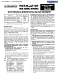
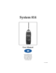
SignalSentry Operation Ð Summary of Procedures
■
Enrolling a 5827BDE in the SignalSentry Mode
■
Returning a 5827BDE to Normal (Non-SignalSentry) Operation
■
Returning All 5827BDEs in the System To Their Normal (Non-SignalSentry) Mode
6. Repeat steps 2 through 5 for each 5827BDE to be returned to
normal operation.
Note: ÊIf there is more than one 5827BDE in the system and
all are to be returned to their normal mode, follow the
procedure in Enrollment Reset, starting at step 2. Otherwise,
proceed to step 7.
Enrolling a 5827BDE as a SignalSentry Device
1. Set 5881EH receiver to the high security mode (if all
5827BDE keypads in the system are to be enrolled in the
SignalSentry mode), by setting DIP switch # 1 in the receiver
to the ON position.
2. Place control panel in Go/NoGo Test mode.
7. Exit the Go/NoGo Test mode on the control panel.
Note that if the 5881EH is in the high security mode and at least
one 5827BDE is in the SignalSentry mode, any 5827BDEs in
the normal mode (and any other wireless keypads) will be
unable to communicate with the system.
3. Power up the 5827BDE.
4. Place 5827BDE in Keypad Programming mode.
5. Key: [★ ] + [6] + [4-digit master code] + [#].
The 5827BDE will beep 3 times and the 3 LEDs will begin
blinking once every 2 seconds.
Enrollment Reset (All 5827BDE Keypads Returned
To Normal Operation)
6. Walk through entire area where the 5827BDE is to be used.
7. Exit the Keypad Programming mode on the 5827BDE.
1. Place control panel in Go/No Go Test mode.
8. Observe that all 3 LEDs blink briefly. If the 5827BDE was
successfully enrolled, the system status will also be
displayed on the 5827BDE after a few seconds (ARM or
READY LED will light). In some systems, the wired keypad
will also emit 3 beeps.
If enrollment was unsuccessful, system status will not be
displayed on 5827BDE.
9. Repeat steps 3 through 8 for all other 5827BDEs.
10 Exit the Go/No Go Test mode on control panel.
2. Power up a 5827BDE.
3. Place that 5827BDE in Keypad Programming mode.
4 Immediately key: [ ★ ] + [3] + [4-digit master code*] + [#].
* Enter code in reverse.
The 5827BDE will beep 3 times and the 3 LEDs will begin
blinking once every 2 seconds. Allow them to blink several
times before going to the next step.
5. Exit the Keypad Programming mode on the 5827BDE.
Returning a 5827BDE To Its Normal Operating
Mode (Non-SignalSentry)
1. Place control panel in Go/NoGo Test mode.
6. If all 5827BDEs in the system were successfully returned to
their normal operating mode and deleted from the 5881EH,
the yellow SEND/REC LED (only) on the 5827BDE will blink
once.
2. Power up the 5827BDE.
7. Exit the Go/No Go Test mode on the control panel.
Note that if all 5827BDEs are in their normal (non-SignalSentry)
mode, the 5881EH receiver will once again be able to
communicate with all wireless keypads, even if the 5881EH
receiver is set to the high security mode.
If you wish to re-enroll one or more 5827BDEs as a
SignalSentry device, follow the procedure under Enrolling a
5827BDE as a SignalSentry Device.
3. Place 5827BDE in Keypad Programming mode.
4. Key: [★ ] + [7] + [4-digit master code] + [#].
The 5827BDE will beep 3 times and the 3 LEDs will begin
blinking once every 2 seconds. Allow them to blink several
times before going to the next step.
5. Exit the Keypad Programming mode on the 5827BDE.
If the 5827BDE was successfully returned to the normal
(non-SignalSentry) mode, the yellow SEND/REC LED (only)
on the 5827BDE will blink once.
5
5827BD/5827BDE SPECIFICATIONS
Physical: 2-3/8" W x 6-1/4" H x 1-1/4" D
(61mm x 159mm x 32mm)
Battery: 9-volt Alkaline. Ademco 464, Duracell MN1604, or Eveready 522 (If a low battery
condition exists, it will be displayed on wired keypads as zone 00.)
LEDs:
Red, Green, and Yellow, for system status indications.
Sounder: Piezoelectric, 4200 Hz, for confirmation, trouble and emergency beeps and
sounding on alarm. In addition, upon lack of response from the control, a long (2
second) beep is heard.
5827BDE Only:
Can provide high security (encrypted) wireless transmissions when used in conjunction with the
5881EH RF receiver. This is made possible through the use of AdemcoÕs new SignalSentry
technology in the 5827BDE and 5881EH.
REFER TO THE INSTALLATION INSTRUCTIONS FOR THE CONTROL PANEL WITH WHICH THIS
DEVICE IS USED, FOR DETAILS ON LIMITATIONS OF THE ENTIRE ALARM SYSTEM.
ADEMCO LIMITED WARRANTY
Alarm Device Manufacturing Company, a Division of Pittway Corporation, and its divisions, subsidiaries and affiliates
("Seller"), 165 Eileen Way, Syosset, New York 11791, warrants its products to be in conformance with its own plans
and specifications and to be free from defects in materials and workmanship under normal use and service for 18
months from the date stamp control on the product or, for products not having an Ademco date stamp, for 12
months from date of original purchase unless the installation instructions or catalog sets forth a shorter period, in
which case the shorter period shall apply. Seller's obligation shall be limited to repairing or replacing, at its option,
free of charge for materials or labor, any product which is proved not in compliance with Seller's specifications or
proves defective in materials or workmanship under normal use and service. Seller shall have no obligation under
this Limited Warranty or otherwise if the product is altered or improperly repaired or serviced by anyone other than
Ademco factory service. For warranty service, return product transportation prepaid, to Ademco Factory Service,
165 Eileen Way, Syosset, New York 11791.
THERE ARE NO WARRANTIES, EXPRESS OR IMPLIED, OF MERCHANTABILITY, OR FITNESS FOR A
PARTICULAR PURPOSE OR OTHERWISE, WHICH EXTEND BEYOND THE DESCRIPTION ON THE FACE
HEREOF. IN NO CASE SHALL SELLER BE LIABLE TO ANYONE FOR ANY CONSEQUENTIAL OR INCIDENTAL
DAMAGES FOR BREACH OF THIS OR ANY OTHER WARRANTY, EXPRESS OR IMPLIED, OR UPON ANY
OTHER BASIS OF LIABILITY WHATSOEVER, EVEN IF THE LOSS OR DAMAGE IS CAUSED BY THE SELLER'S
OWN NEGLIGENCE OR FAULT.
Seller does not represent that the products it sells may not be compromised or circumvented; that the products will
prevent any personal injury or property loss by burglary, robbery, fire or oth erwise; or that the products will in all
cases provide adequate warning or protection. Customer un derstands that a properly installed and maintained alarm
may only reduce the risk of a bur glary, robbery, fire or other events occurring without providing an alarm, but it is not
insurance or a guarantee that such will not occur or that there will be no personal injury or property loss as a result.
CONSEQUENTLY, SELLER SHALL HAVE NO LIABILITY FOR ANY PERSONAL INJURY, PROPERTY DAMAGE
OR OTHER LOSS BASED ON A CLAIM THE PRODUCT FAILED TO GIVE WARNING. HOWEVER, IF SELLER IS
HELD LI ABLE, WHETHER DIRECTLY OR INDIRECTLY, FOR ANY LOSS OR DAMAGE ARISING UN DER THIS
LIMITED WARRANTY OR OTHERWISE, REGARDLESS OF CAUSE OR ORIGIN, SELLER'S MAXIMUM
LIABILITY SHALL NOT IN ANY CASE EXCEED THE PURCHASE PRICE OF THE PRODUCT, WHICH SHALL BE
THE COMPLETE AND EXCLUSIVE REMEDY AGAINST SELLER. This warranty replaces any previous warranties
and is the only warranty made by Seller on this product. No increase or alteration, written or verbal, of the obligations of this Limited Warranty is authorized.
ALARM DEVICE MANUFACTURING COMPANY
A Division of Pittway Corporation
165 Eileen Way, Syosset, New York 11791
Copyright © 1993 PITTWAY CORPORATION
N6484V3 3/96
6