1
PCSC
LiNC-NET 5.11.2 for Windows
Administrator Guide
Standalone and Multi-User
38-10051-001
REV: A
PCSC
3541 Challenger Street
Torrance, CA 90503
Phone: (310) 638-0400
FAX: (310) 638-6204
www.1pcsc.com
LiNC-NET 5.11.2 Admin Guide
38-10051-001
Page 1 of 264
PCSC
First Edition - Revision A: May 2000
Information in this manual is subject to change without notice and does not represent a commitment on the part of PCSC. The software described in this manual is furnished under a license
agreement or nondisclosure agreement. The software may be used or copied only in accordance
with the terms of the agreement. No part of this document may be reproduced or transmitted in any
form or by any means, electronic or mechanical, including photocopying, recording, or information
storage and retrieval systems, for any purpose other than specied in the agreement, without the
express written permission of PCSC.
© 2000 PCSC. All Rights Reserved.
Printed in the United States of America.
Microsoft Windows-NT/98 © is a trademark of Microsoft Corporation.
Published by PCSC
3451 Challenger Street
Torrance, CA 90503
(310) 638-0400
Publication Number: 38-10051-001
LiNC-NET 5.11.2 Admin Guide
38-10051-001
Page 2 of 264
PCSC
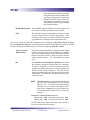
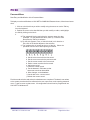
Release Notes for LiNC-NET NT/98 Version 5.11.2
1. Linc-ID- This feature allows the operator to take pictures and print badges.
2. Bulk Download- Bulk Download allows for a faster method of downloading the database to the panels over a LAN. Previously, downloads were done using the “primary
port,” sending records one at a time. Bulk Download is accomplished by using a “secondary port.” The “secondary port” is a TCP/IP connection used to send the database
in “big” blocks.
3. Department by Name- The department eld in the card denition record is updated
by making a selection in a window containing all of the dened departments. New
departments are dened by using the Add button, and the existing departments can be
changed or deleted using the Edit and Delete buttons in the Department window. The
Find eld at the top of the Department window facilitates the search for a department
by allowing the user to enter the department name.
4. 2000 Authorization Groups- The number of authorization group records has been
increased to 2000. A warning is displayed before a delete of the authorization group is
processed.
5. 1000 Mapped Time Periods- The number of time periods has been increased to 1000.
Time periods 2 through 999 are user-denable. Each MicroLPM has 32 time periods-0,
1, and thirty time periods selected from the range of 2 and 999. Each user-denable
time period also has a name eld associated with it.
6. Alarm Break-Through- Priority zero (0) alarms will force the alarm task to be the topmost task.
7. Display and Data Entry- The LiNC-NET windows now ll the entire screen and have
border icons-minimize, maximize, and close. The speed buttons are now on tool bars
that can be rearranged. Speed buttons are disabled rather than hidden when the
operator does not have access to them. Speed buttons for door status, input status,
and output status have been added. Pressing a number key in an edit eld or time
period, authorization group, afliation, department, and some card numbers will bring
up a window which will allow the operator to make a selection from a list.
8. Latched Alarm- SIM rmware provides a latching option for each alarm point. When
the latching option is selected to input, only the rst occurrence of an alarm condition will
be reported to the host. All subsequent alarm conditions will be ignored until acknowledgement is received from the host. The latching option has three modes-Standard,
Access, or Bypass. All alarm conditions are monitored in the Standard mode, whereas
only the trouble conditions are monitored in the Access mode. In the Bypass mode
all alarm conditions all alarm conditions are ignored. If an input is dened as a latching, an alarm denition record is automatically added. Input alarms for latched inputs
CANNOT be shunted or deleted. Attempting to delete an alarm denition record for a
latched input will cause the message, “Unable to delete record for latched alarm,” to be
displayed.
LiNC-NET 5.11.2 Admin Guide
38-10051-001
Page 3 of 264
PCSC
9. Baud Rates- New baud rates: 14.4K, 19.2K, 38.4K, 56K, 115.2K, 128K, and 256K.
10. Delete Card Correction- This release corrects the problem in which a card is still
usable at the panel after deleting it from the database.
11. Program Level- The operator is no longer allowed to set the program level for the
Card Personal menu to a value higher than the value for the Card Change menu on
the User page. The problem in which menu items were not correctly shown or hidden
when program levels restricted the operator’s access to some of the menu items has
been corrected.
12. Floor Group Range Check- on the card screens, illegal values are not accepted in
the oor group elds.
13. Card Add- Personal data is no longer copied from the template when adding cards.
(STR#97121007)
14. Out#1/ALM- On the Hardware page of the MicroLPM Setup screen, the “OUT#1/
ALM” checkbox is used for both OUT#1 and the ALM boards.
15. Report- As child windows are opened in the report task, the parent window is minimized. The parent window is restored when its child widow is closed. The problem
of duplicate tabs on the report screens has been corrected.
16. CongLN-42 “Allow Uploads” enables the UPLOAD icon in LiNC-NET. The UPLOAD
of the database from a Panel should be done sparingly (if at all).
17. Photo Trace- a new feature that allows the user to assign a photo to each cardholder.
When a card is used, the cardholders photo can be displayed. Should a card be
denied, an access option for allowing the door open from a PC is possible.
18. Modem Initialization String- the modem initialization string for a port is now specied in the Host Computer screen. To accommodate the additional components, the
Loop and Port denition have been split into two pages. The ‘Port’ page contains the
modem initialization elds.
19. Floor Buttons- Sense Inputs 56-71 may be dened as Floor button Type sense
inputs. However, MicroELV rmware must be version 5.9.11 or later. Currently this
rmware is still under development to support destination reporting with a single oor
latching resource.
20. Renewable Shunt- this option has been added to the Features page of the MicroLPM
setup screen to allow the user to enable this feature.
21. Supervised Alarms- a checkbox has been added to the Input screen to allow the user
to indicate that an input is supervised.
22. Corp_1000- The reader type “Fortune500” has been renamed to “Corp_1000”
23. SIM32- the SIM32 has been added to the Model list in the MicroLPM setup/hardware
screen.
LiNC-NET 5.11.2 Admin Guide
38-10051-001
Page 4 of 264
PCSC
24. Daylight Savings- The start and the stop dates for the daylight savings feature are
now initialized to March 3, 1980 and October 29, 1980, respectively.
25. Card Format Settings: Global/Park and PIN/Date- Defaults for card format settings
have been changed to Global and PIN. Making a selection from the drop down list for
one of these elds will automatically change the selection for the other.
26. Active Alarm Files- The active alarm les (ActiveTA and ActiveXA) are no longer in
the list of les that can be created in ConFigLN. They are re-created each time LiNCNET is started.
27. Password Valid Time Period- If an attempt is made to sign on at a time when the time
period for the password is not active, “Time period not active” message is displayed.
28. Program Level for Input Status- The program level for the Input Status command
has been corrected.
29. Loop/Port Conguration- While the “Request Online” is checked for a MicroLPM, the
conguration cannot be changed for the loop/port used by that panel.
30. Loop/Port Conguration- Added Loop Ports 5-13 in Host Setup icon.
31. Com/Port Conguration- Added Comports 5-13 in the Host Setup icon.
32. Concentrator Conguration- Added Concentrators in the Host Setup when congured to use 1-20.
33. CongLN-The Task Communications options on the Main page have been changed to
allow conguration for workstations and concentrators.
-EPISUITE in use has been renamed to Photo imaging.
- Modem page has been removed. Modem initialization strings are specied
on the Host Computer/Port screen.
- The LiNC-ID box has been added toenable the icon in the LiNC-NET
system side.
-The Upload checkbox has been added toenable the icon in the LiNC-NET
user side.
-ELV: Max One button box has been added to enable sense input oor
buttons 56-71 the ELV rmware 5.9.11 or higher.
-Concentrator on Network radial button has been added to setup the system
conguration with the concentrators.
- I Am Concentrrator radial button has been added to setup the PC as a
concentrator.
LiNC-NET 5.11.2 Admin Guide
38-10051-001
Page 5 of 264
PCSC
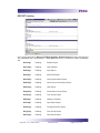
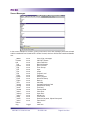
Table of Contents
Administrator Guide for LiNC-NET 5.11.2...................................
Release Notes for LiNC-NET 5.11.2.........................................
1
3-5
Table of Contents..........................................................................
6-10
Introduction...................................................................................
Installation and Setup...............................................................
12
13
Step 1- Before You Begin- Installation Requirements...............
Software.............................................................................
Hardware...........................................................................
Hardware Item....................................................................
14
15
15
15
Step 2- The Initial Installation......................................................
To Begin.............................................................................
Installing BDE-4.................................................................
Installing 5.11.2..................................................................
16
17
18-20
21-24
Step 3- Copy LinnetW.ini to the LNv5.11.2 Program................
Copy LinnetW.ini to the LNv5.11.2 Program Folder..........
25
26-27
Step 4-Using ConFigLN to Install a Directory................
A Brief Word about Stallions®............................................
Installing LiNC-NET for a Standalone System...................
Installing LiNC-NET for Multi-user Host Conguration......
Installing LiNC-NET for a Multi-User Concentrator Conguration
Installing LiNC-NET for a Multi-User Workstation..............
28
29
30-31
32-33
34-35
36-37
Step 5- Using ConFigLN to Create a Database...........................
Part 1- Creating the LiNC-NET Database Folder................
Option: Using a Shared Dive in a Multi-User System
(Host or Workstation)..........................................
.
Part 2 - Conguring the Borland Database Engine (BDE)..
Part 3- Creating the LiNC-NET Database...........................
Part 4- Setting Up your Data Files......................................
Create Data Base: Default Values: Card Technology
Create Data Base: Default Values: Door Lock Access Time
Create Data Base: Default Values: Card Table Format
Primary Expiration....................................
PIN or Expiration Date (Parking Readers).
Names for Cardholders Exist.....................
12-Digit Card Number................................
Create Data Base: Default Values: Daylight Savings
Create Data Base: Default Values: Entry/Exit Enforcement
Strict Entry/Exit...........................................
Lenient Entry/Exit.......................................
Soft Entry/Exit............................................
Create Data Base: Files.......................................
Create Data Base: Main.......................................
38
39
LiNC-NET 5.11.2 Admin Guide
38-10051-001
40-42
43
44-45
46-47
48
49
50
50
50
50
51
51
51
51
52
52
52
5
Page 6 of 264
PCSC
Step 6- Conguring your Panel(s) with ConFigUL.....................
Connecting to a Panel through a Direct Connection...........
Connecting to a Panel(s) through a LAN connection..........
Changing a Panel’s Number................................................
Changing the Panel’s Password..........................................
Changing the Direct Connection/MODEM Conguration.....
Changing the Connection Baud Rate- Modem/Direct..........
Add/Change Panel-Modem Telephone Numbers.................
Logging off from a Panel......................................................
Exiting ConFigUL.................................................................
ConFigUL- Conguration Glossary.......................................
54
55-56
57-58
59-60
60
60
61
61
62
62
63-64
Step 7-Using LiNC-NET...................................................................
Part 1- Coming and Going....................................................
Starting LiNC-NET.....................................................
Exiting LiNC-NET.......................................................
Part 2- System Commands and Menus.................................
System Commands..................................................
The System Commands Menu and Tool Bar
Data Entry and Modication..........................
Bulk Initialization......................................................
Making Changes in Bulk Initialization............
Bulk Initialization: Card Technology...............
Bulk Initialization: Door Lock Access Time....
Bulk Initialization: Card Table Format............
Bulk Initialization: Daylight Savings...............
Bulk Initialization: Entry/Exit Enforcement.....
Site/Host Computer- <Alt>S, H...............................
Host Computer: About...................................
Host Computer: Loop....................................
Host Computer: Port......................................
Adding or Deleting a Panel............................
Site/MicroLPM...........................................................
Site/MicroLPM: Features...............................
Site/MicroLPM Setup: Hardware...................
Site/MicroLPM: Address................................
Door...........................................................................
Overview.........................................................
Door Overview: Time Related.........................
Door Overview: Hardware...............................
Door Overview: Features................................
Door Overview: Access Actions......................
Access Action (at the Reader)........................
Hardware-Input..........................................................
Hardware-Output.......................................................
Floor Groups (ELV).........................................
Card............................................................................
Add Card........................................................
Changing Cards - C for Change.....................
Change Card: Standard Access...............
65
66
66
66
67
67-70
71
71
72
72
73
74
74
75
75-76
77
78
79-84
85
86
87
87-91
92-98
99
100
100
101-103
104-111
112-114
115-117
118-119
120-123
124-128
129-131
132
132-137
138
139-141
LiNC-NET 5.11.2 Admin Guide
38-10051-001
Page 7 of 264
PCSC
Change Card: Advanced Access .............
Change Card: Employee.........................
Change Card: Vehicles............................
Change Card: Personal...........................
Change Card: Emergency........................
Change Card: Status................................
Change Card: Select Fields.....................
Integrity................................................................
Backup to Selected Drive........................
Upload from MicroLPM............................
Field Denitions.......................................
Password..............................................................
Field Denitions.......................................
Program Level Conguration.............................
Program Level Hierarchy.........................
Alarms..................................................................
Transaction Alarms..................................
Transaction Alarms Originating at the Panel
Transaction Alarms Originating at the Host
Alarm Acknowledgment-Press Alarm Clock
Logger .................................................................
User- <Alt> U.......................................................
Logoff- <Alt> L....................................................
Help- <Alt> H.......................................................
Printing a Help Topic.................................
Traveling through the Help Screens..........
Reports- <Alt> Tab.................................................
Generate a Report....................................
Search.......................................................
Display......................................................
Setup: Reports- Printer Attributes............
Report Headings..................................................
History-.....................................................
Setup: History Reports- Display ..............
Setup: History Reports- Search..............
Setup: History Reports- File...................
Host.........................................................
MicroLPM................................................
Reader.....................................................
Input.........................................................
Output......................................................
Floor Groups............................................
Card (Authorization)................................
Authorization Group................................
Card (Personal) ......................................
Card Status.............................................
Time Period.............................................
Holiday List.............................................
Input Alarm..............................................
Xaction Alarm...........................................
LiNC-NET 5.11.2 Admin Guide
38-10051-001
141-145
146
147
148
149
150-153
154-156
157
157-158
159
160
161-162
163
164-165
165-167
168-169
170-171
172-174
175
176
177-178
179
179
180
180
181
182
182
183
183
184
185
185
185
186
186
187
188
189
190
191
192
193-195
196-197
198
199
200
201
202
203
Page 8 of 264
PCSC
Part-3- Miscellaneous.......................................................
Understanding Control Counters......................
Table of Inputs, Computations, and Outputs
Examples.............................................................
EXAMPLE A: Programming an Alarm to
Activate an Output Horn.........................
EXAMPLE B: Program Activation of an
Output Horn When a Door is Left Open..
EXAMPLE C: Program De-activation of
an Output Horn When a Door is Closed..
EXAMPLE D:Program Automatic Door
Open During Working Hours....................
EDDAT.................................................................
Files..........................................................
Lists..........................................................
Menu Items...............................................
REPORT Heading....................................
Screen Messages....................................
Dictionary Translator: FindDat..........................
Communication between LiNC-NET 5.11.2
for Windows and the Panels...............................
LiNC-NET Initialization of Direct Connect Panels
Access the Site/Host Computer Menu:.....
Date Format Modication
(for expiration date into the year 2000).............
Adding a Client Database..................................
Before a client database can be created,
two things must occur:..............................
Conguring Windows 98
to Display All Files....................................
Adding Facility Code for Client.................
LiNC-NET Multi-User Systems...........................
LiNC-NET NT System..............................
PC to PC Cabling.....................................
Hub to PC Cabling....................................
Updating/Upgrading to LiNC-NET 5.11.2 for Windows
Upgrade Reference Chart - Required Files
to be Created from Earlier Versions.........
Printer Text Setup...............................................
Step 8-Worksheets.......................................................................
Bulk Initialization Worksheet..............................................
Host Computer Worksheet.................................................
Panel Setup Worksheet......................................................
MicroLPM Models..............................................................
Door Overview Worksheet (First Reader)...........................
Access Actions (First Reader)............................................
Door Overview Worksheet (Second Reader).....................
Access Actions (Second Reader)......................................
Input Worksheet.................................................................
Output Worksheet..............................................................
LiNC-NET 5.11.2 Admin Guide
38-10051-001
204
205
205
206
207
208
209
210
211
212
213
214
215
216-217
218
219
220
220-221
222
223
223
223
224-225
226
226
227
227
228-230
231
232
233
234
235-237
238-240
241
242-243
243-244
245
246-247
248
249
Page 9 of 264
PCSC
Elevator Relay to Control Counter Cross Reference Table
Floor Groups Worksheet....................................................
Add Card /Change Card Worksheet..................................
Password Worksheet.........................................................
Alarm Denition Worksheet...............................................
Transaction Alarms-Host....................................................
Transaction Alarms-MicroLPM...........................................
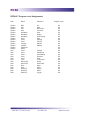
DEFAULT Program Level Assignments..............................
Program Level Data Entry Worksheet................................
Password Menu..................................................................
Program Level Worksheet..................................................
End of Manual..............................................................................
LiNC-NET 5.11.2 Admin Guide
38-10051-001
250
251-254
255
256
257
258
259
260
261
262
263
264
Page 10 of 264
PCSC
This page is intentionally blank.
LiNC-NET 5.11.2 Admin Guide
38-10051-001
Page 11 of 264
PCSC
Introduction
Welcome to LiNC-NET for Windows-NT/95/98, the programming software from PCSC. This user-friendly, PC-based access
control manager is simple to operate and provides Help screens
along the way to make operation even easier.
LiNC-NET for Windows-NT/95/98 operates under the Microsoft
WINDOWS-NT/95/98 operating system. The host PC should
be dedicated to the access control system to ensure security
integrity and management efciency. Other WINDOWS-NT/
95/98 applications should not be running concurrently with LiNC-NET for Windows-NT/95/98.
LiNC-NET has been designed to function on two separate levels: Administrator and User.
Though there is an overlap in the information provided for both the System and User commands,
this manual has been designed to provide information for the Administrator level of LiNC-NET. To
obtain a complete understanding of LiNC-NET, this manual should be used in conjunction with the
LiNC-NET for Windows- NT/95/98 User Manual.
This manual was designed for LiNC-NET system administrators. Although this manual provides
a general survey of the hardware and system setup, the Installation Manual(s) specic to your
panel(s) should be used in conjunction with this system guide. The Help menus provided onscreen will usually be sufcient to enter the proper data. This manual augments those screens and
will detail certain elds, denitions, and procedures where needed.
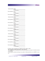
Panel Installation Manuals
MicroLPM
IQ
SIM
Ultimate
(P/N 33-10019-001)
(P/N 33-10036-001)
(P/N 33-10037-001)
(P/N 33-10035-001)
Peripheral Installation Manuals
Modem
Stallion
Lantronix
(P/N 33-10052-001)
(P/N 33-10060-001)
For clarity in describing the use of LiNC-NET, the MicroLPM, IQ, SIM and Ultimate
PCBs will be referred to as the PANEL.
LiNC-NET 5.11.2 Admin Guide
38-10051-001
Page 12 of 264
PCSC
Installation and Setup
Along with the Help screens, this guide describes how to setup your system quickly and easily.
In addition, the worksheets provided in the back of the guide will assist in organizing the information, door overview, access operations, door input and output actions, card additions, uploading
records from the panel, and password assignments. After the initial system foundation has been
setup, refer to the LiNC-NET for Windows-NT/95/98 User Guide (Part#- 37-10050-001) for the dayto-day operation and maintenance of your system. The User Guide provides information on entering data regarding card assignment, time periods, downloading records to the Panel(s), and door
operations.
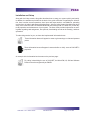
To make things easier for you, we have also implemented information boxes:
These information boxes will appear in areas to give warnings or reiterate important
points
These information boxes will appear in areas to dene or clarify some of LiNC-NET’s
properties
An example is the information box that was on the previous page:
For clarity in describing the use of LiNC-NET, the MicroLPM, IQ, SIM and Ultimate
PCBs will be referred generally as PANEL.
LiNC-NET 5.11.2 Admin Guide
38-10051-001
Page 13 of 264
PCSC
Step 1- Before You Begin- Installation Requirements
LiNC-NET 5.11.2 Admin Guide
38-10051-001
Page 14 of 264
PCSC
Software
To install LiNC-NET for Windows-NT/95/98, the following requirements must be met:
-Windows NT Workstation Version 4.0 S/P 4, Windows 95, or Windows 98 installed
on the host computer.
-Knowledge of mouse and keyboard use in the WINDOWS-NT/95/98 environment.
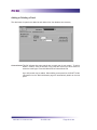
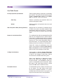
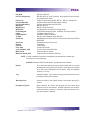
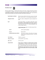
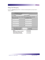
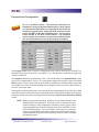
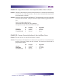
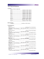
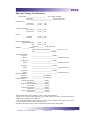
Hardware
Compare your computer hardware features with the chart listing the requirements for proper operation of LiNC-NET. If you have any questions regarding the computer you will be using for this
application, call PCSC Customer Support at (310) 638-0400 ext. 694.
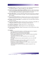
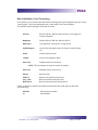
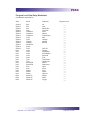
Hardware item
Min. Requirement
CPU
IBM PC or equivalent: Pentium
(minimum 200 MHz for Host,
133 MHz for Work Station),
Windows-NT version 4.0, or 95,
Award BIOS, Intel 82430 VX PCI
Chipset
RAM
64 MB for Host & 32 MB for Workstation
Hard Drive
1.2 GB IDE
Diskette Drive
3.5 in., 1.44 MB
CD ROM
4X CD ROM drive
Monitor
SVGA, 640 x 480, 16 color
Keyboard
AT type
Mouse, Trackball
WINDOWS compatible Bus or
PS2 Mouse
Parallel Port
LPT1 (Address 0378h IRQ7) preferred
but LPT2 or LPT3 are acceptable
Serial Port
2 RS-232, 1 RS485 (COM 1 then COM 4
optically isolated preferred).
U.P.S.
(Uninterruptable Power Supply)
420 VA for PC & monitor
Network Interface Card
(NT compatible)*
10-100 MBs Ethernet LAN card
Zip Drive
LS-120 (optional- available via PCSC)
1.44MB – 20MB of Archived Information
per diskette
* Optional- NIC (Network Interface Card) is required only in a Multi-User LiNC-NET environment
LiNC-NET 5.11.2 Admin Guide
38-10051-001
Page 15 of 264
PCSC
Step 2-The Initial Installation
LiNC-NET 5.11.2 Admin Guide
38-10051-001
Page 16 of 264
PCSC
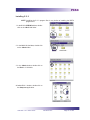
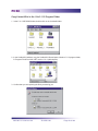
The Initial Installation
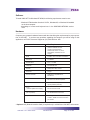
To Begin
1. Close any Windows programs that you are currently running before beginning
the installation.
2. Insert the LiNC-NET v. 5.11.2 CD-ROM into the CD-ROM drive.
3. Click on the My Computer icon on your desktop.
4. Your CD-ROM drive should display 5.11.2. Double-click on 5.11.2.
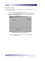
5. You will see several folders in the 5.11.2 window:
From this location you will install the BDE-4 and 5.11.2 programs which form the two halves of the
LiNC-NET 5.11.2 program. We will start with the BDE-4 program.
The Installation of LiNC-NET is in two parts because it is comprised of
-5.11.2 PCSC LiNC-NET Application Software
-Borland” Data Base Engine Software
BDE-4- Borland Data Base Engine Version 4 software permits the operation of a database for use by LiNC-NET (the installation will also
read, write and update an existing Borland Database by the LiNCNET Application program)
LiNC-NET 5.11.2 Admin Guide
38-10051-001
Page 17 of 264
PCSC
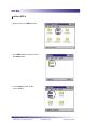
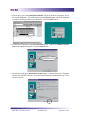
nstalling BDE-4
1. Double-click on the BDE-4 folder.
2. In the BDE-4 window, double-click on
the 144mb folder.
3. In the 144mb window, doubleclick on Disk 1.
LiNC-NET 5.11.2 Admin Guide
38-10051-001
Page 18 of 264
PCSC
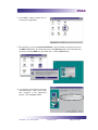
4. In the Disk 1 window, double-click on
the setup.exe application.
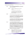
5. This will bring you to the Install Shield Wizard“, which will lead you through the rest of
the BDE-4 installation. The initial page will be the Welcome page, which will state that
you will be installing BDE-4 on your hard drive. Click the Next> button.
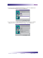
6. You will then be brought to the User
Information page. Type in your Name
and Company in the appropriate
spaces. Click the Next> button.
LiNC-NET 5.11.2 Admin Guide
38-10051-001
Page 19 of 264
PCSC
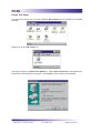
7. You will be brought to the Choose
Destination Location page. A default
directory (C:\Program Files\PCSC\
BDE4) will have already been established for you. Click the Next> button.
8. You will be brought to the Select Program Folder page. A default folder
(BDE 4) will have already been established for you. Click the Next> button.
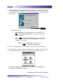
9. You will be brought to the Start Copying Files page, which will specify your
Current Settings that you have established in the previous pages. Click the
Next> button.
10. The BDE les will now decompress
onto your hard drive. When the
decompression is nished, you will
be brought to the Setup Complete
page. Click the Finish button.
11. You will be brought back to your Windows“ desktop. Return to the 5.11.2 CD ROM
window. You are now ready to install the 5.11.2 program.
LiNC-NET 5.11.2 Admin Guide
38-10051-001
Page 20 of 264
PCSC
Installing 5.11.2
NOTE Installing the 5.11.2 program les is very similar to installing the BDE-4
program les.
1. In the 5.11.2 CD ROM window, doubleclick on the LNv 5.11.2 folder.
2. In the LNv 5.11.2 window, double-click
on the 144mb folder.
3. In the 144mb window, double-click on
the Disk 1 of 19 folders.
4. In the Disk 1 window, double-click on
the Setup.exe application.
LiNC-NET 5.11.2 Admin Guide
38-10051-001
Page 21 of 264
PCSC
5. This will bring you to the Install Shield Wizard“, which will lead you through the rest of
the 5.11.2 installation. The initial page will be the Welcome page, which will state that
you will be installing 5.11.2 on your hard drive. Click the Next> button.
6. You will then be brought to the User Information page. Type in your Name and Company in the appropriate spaces. Click the Next> button.
7. You will be brought to the Destination Location page. A default directory (C:\Program\
Files\PCSC\LiNC-NET version 5.11.2) will have already been established for you. Click
the Next> button.
LiNC-NET 5.11.2 Admin Guide
38-10051-001
Page 22 of 264
PCSC
8. You will be brought to the Select Program Folder page. A default folder LNv5.11.2 will
have already been established for you. Click the Next button.
9. You will be brought to the Start Copying Files page, which will specify your Current
Settings that you have established in the previous pages. Click the Next> button.
LiNC-NET 5.11.2 Admin Guide
38-10051-001
Page 23 of 264
PCSC
10. The 5.11.2 les will now decompress onto your hard drive. A 5.11.2 window will come
up briey, showing the LiNC-NET icons that are being installed. When the decompression is nished, you will be brought to the Setup Complete page. In the page will be
a box stating:
FINISH
You have two choices:
-(Recommended) Click the Finish button without checking the
Yes, Launch the program les. This will return you to the
Windows desktop.
-Check the Yes, Launch the program les then click the Finish
button. This will immediately launch ConFigLN so that you can
complete your installation.
NOTE It is recommended that you do not select
the Yes, Launch the program les.
11. Click on the Finish button. You will be brought back to your Windows desktop.
12. On the desktop, you will see an open window with icons for different LiNC-NET utilities.
These can be placed on the desktop to as shortcuts to the different programs.
One can also access the different LiNC-NET programs through the Start menu,
in Programs under LNv 5.11.2 folder.
At this point, you are ready to start Step 3.
LiNC-NET 5.11.2 Admin Guide
38-10051-001
Page 24 of 264
PCSC
Step 3-
Copy Lincnet W.ini to the LNv5.11.2
Program Folder
LiNC-NET 5.11.2 Admin Guide
38-10051-001
Page 25 of 264
PCSC
Copy Lincnet W.ini to the LNv 5.11.2 Program Folder
1. In the 5.11.2 CD ROM Window, double-click on the LincNetW folder.
2. In the LincNetW.ini window, copy the LincNetW.ini le and paste it intothe 5.11.2 program folder,
C:\Program Files\Pcsc\LiNC-NET version 5.11.2 (default path).
3. Conrm that you are replacing the le by answering yes.
LiNC-NET 5.11.2 Admin Guide
38-10051-001
Page 26 of 264
PCSC
4. Go to Start\Programs\LNv5.11.2\CongLN.
a. Select the Set defaults. This will give you the proper LincnetW.ini.le that you purchased.
b. Save by clicking on the Write tab. Selecting the Write tab will add a duplicate le
called LincnetW.ini in your WINNT folder.
NOTE
Facility code for site will be implemented into the WINNT\
LincnetW.ini site code string. LiNC-ID will be implemented if
purchased for the system.
LiNC-NET 5.11.2 Admin Guide
38-10051-001
Page 27 of 264
PCSC
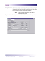
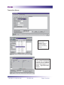
Step 4- Using CongLN to Install a Directory
CongLN- (Congure LiNC-NET) is a feature that
is used to set options such as the location of the LiNC-NET data base (on a
local hard drive or mapped to a shared
network drive) and to install the default
features of the LiNC-NET system.
Choose one of the following installation procedures:
· Installing LiNC-NET for a Standalone System
· Installing LiNC-NET for a Multi-User Host Conguration
· Installing LiNC-NET for a Multi-User Concentrator Conguration
· Installing LiNC-NET for a Multi-User Workstation Conguration
LiNC-NET 5.11.2 Admin Guide
38-10051-001
Page 28 of 264
PCSC
A Brief Word about Stallions®
Stallions® In order to increase the number of panels that can be accessed through
a Host in a Standalone system or a Concentrator in Multi-User system,
eight additional com ports may be added through the use of an external
stallion.
A Host or Concentrator PC may function using two external Stallions®. However,
LiNC-NET 5.11.2 software limits each Concentrator to a maximum of 13 COM
ports.
The use of Stallions® is now possible in LiNC-NET 5.11.2 for either a Host in a Standalone system
(allowing an interface of up to 200 panels in one system) or through the use of concentrators
(allowing an interface of up to 4,000 panels in one system).
Though LiNC-NET will function using Stallions®, the installation and conguration of Stallions® to a
site are beyond the focus of this manual. An explanation of Stallion® installation and conguration
can be found in PCSC Technical Bulletin 39-10060-001(Stallion® Easy Connection Dual Interface
Module).
LiNC-NET 5.11.2 Admin Guide
38-10051-001
Page 29 of 264
PCSC
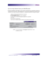
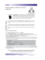
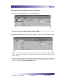
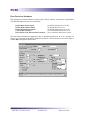
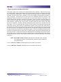
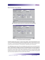
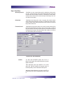
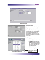
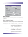
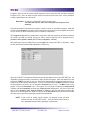
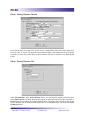
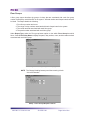
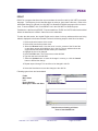
Installing LiNC-NET for a Standalone System
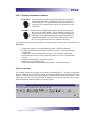
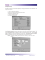
1. Go to Start\Programs\LNv5.11.2 and click on ConFigLN.
The default value in the Task Communication shows a stand-alone computer equipped with a
network card. This means that the computer will be able to connect to the panel through the network (LAN, WAN), direct cable (RS232 / RS485) or remote access (modem).
Network Card- A Network Interface Card (NIC) is an Ethernet communication
hardware device inserted in a computer allowing it to communicate
with a local area network (LAN). An Ethernet is a network architecture that accommodates communications at 10 megabytes/100
megabytes per second between PC’s over a BUS topology
2. If you are using a network card with your system, click on Netcard on Board in the Task Communication section.
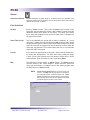
NOTE If the computer isn’t equipped with a network card or you will not use a
LAN connection in your LiNC-NET operations, do NOT check Netcard on
Board.
A computer without a Network Card will connect to a panel only with a
direct cable (RS232 / RS485) or with a remote connection (modem).
3. As soon as the conguration desired is set in the Task Communication section, save it by clicking once on the Write button located in the top left side of the screen.
LiNC-NET 5.11.2 Admin Guide
38-10051-001
Page 30 of 264
PCSC
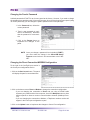
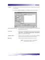
If you are using a Network Card in your LiNC-NET SystemDuring the installation of LiNC-NET on your computer, Dssock32.ocx is registered to enable the
communication of LiNC-NET network applications. In the event of changes to your system or your
computer, you are given the option to Register (i.e. reregister) Dssock32.ocx through ConFigLN.
1. Make sure Netcard on Board button is checked.
2. Click on Register OCX...
3. In the Register OCX window, click on Register.
4. Another pop-up window will appear saying OCX is registered.
5. Click OK.
6. Click Close to register OCX.
7. Click once on the Write button located in the top left side of the screen.
NOTE It is not necessary to Unregister Dssock32.ocx in the
installation process.
LiNC-NET 5.11.2 Admin Guide
38-10051-001
Page 31 of 264
PCSC
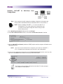
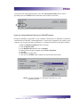
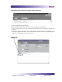
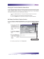
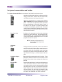
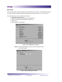
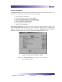
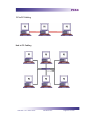
Installing LiNC-NET for Multi-User Host
Conguration
Host
is the computer that will manage the database, display the information and
monitor alarms associated with each workstation that it is connected to it.
NOTE
Before installing LiNC-NET- v. 5.11.2 on the Host PC or
Workstation PC, you must congure all computers to communicate to each other through the network using TCP/IP
as the main protocol.
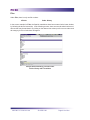
1. Go to Start\Programs\LNv5.11.2 and click on ConFigLN.
2. In the Task Communication section, be sure that the Netcard on Board is checked.
3. Click on LiNC-NET on Network (disables CLIENTs) option and the computer will default to the
I am Host selection.
NOTE
I am Host must be selected if the computer is the Host for LiNC-NET v.
5.11.2. All panels are connected to the Host PC in this conguration.
4. As soon as the conguration desired is set in the Task Communication section, save it by clicking once on the Write button located in the top left side of the screen.
The Panels receive the date and time from the Host PC in this conguration-except the modem panels.
LiNC-NET 5.11.2 Admin Guide
38-10051-001
Page 32 of 264
PCSC
If you are using a Network Card in your LiNC-NET SystemDuring the installation of LiNC-NET on your computer, Dssock32.ocx is registered to enable the
communication of LiNC-NET network applications. In the event of changes to your system or your
computer, you are given the option to Register (i.e. reregister) Dssock32.ocx through ConFigLN.
1. Make sure Netcard on Board button is checked.
2. Click on the Register OCX...
3. In the Register OCX window, click on Register.
4. Another pop-up window will appear saying OCX is registered.
5. Click OK.
6. Click Close to register OCX.
7. Click once on the Write button located in the top left side of the screen.
NOTE It is not necessary to Unregister Dssock32.ocx in the
installation process.
LiNC-NET 5.11.2 Admin Guide
38-10051-001
Page 33 of 264
PCSC
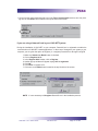
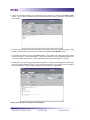
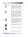
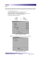
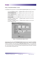
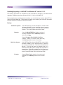
Installing LiNC-NET for a Multi-User Concentrator
Conguration
Concentrator- A special application of a PC that is not the Host or one of the
Workstations. A concentrator operates as a router by LiNC-NET
to function as an interface between the Host PC and (up to) 200
panels. LiNC-NET 5.11.2 will support up to 20 concentrators in one
system, permitting a Host to monitor up to 4000 panels!
If your LiNC-NET system includes Concentrators, the Host is not able to connect
directly to the system panels. All panels have to be connected through the Concentrators.
Concentrators will often operate in a system with Workstation PCs. However, at this
time, LiNC-NET 5.11.2 does not allow Concentrators to function as Workstations.
Panels receive their date and time from each concentrator PC-except modem
panels.
Using a Concentrator System
1. Go to Start\Programs\5.11.2 and click on ConFigLN.
2. In the Task Communication section, be sure that the Netcard on Board is checked.
3. Click on LiNC-NET on Network (disables CLIENTs) option and the computer will be set, per
default, as a Host in a multi-user environment (I am Host selected).
4. Select the I am Concentrator option.
5. In Local PC Number scroll menu, choose a number between 1 and 20. This number must be
unique for each concentrator (PC) installed in the multi-user environment. The example below
indicates 5 as the Local PC Number.
6. In the Host PC name window, type the Host computer name (check in Control Panel\Setting\
Network\Identication tab in the Host computer, if needed). The example above uses HOST
as the HOST PC name.
NOTE If the computer is a Concentrator, I am Concentrator must be selected.
Each concentrator must be assigned a unique Local PC number (from 1 to
20) and the Host computer name that the concentrator is connected.
LiNC-NET 5.11.2 Admin Guide
38-10051-001
Page 34 of 264
PCSC
1. As soon as the conguration desired is set in the Task Communication section, save it
by clicking once on the Write button located in the top left side of the screen.
If you are using a Network Card in your LiNC-NET systemDuring the installation of LiNC-NET on your computer, Dssock32.ocx is registered to enable the
communication of LiNC-NET network applications. In the event of changes to your system or your
computer, you are given the option to Register (i.e. reregister) Dssock32.ocx through ConFigLN.
1. Make sure Netcard on Board button is checked.
2. Click on Register OCX...
3. In the Register OCX window, click on Register.
4. Another pop-up window will appear saying OCX is registered.
5. Click OK.
6. Click Close to register OCX
7. Click once on the Write button located in the top left side of the screen.
NOTE It is not necessary to Unregister Dssock32.ocx in the
installation process.
LiNC-NET 5.11.2 Admin Guide
38-10051-001
Page 35 of 264
PCSC
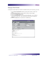
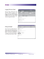
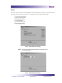
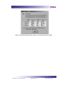
Installing LiNC-NET for a Multi-User Workstation
Workstation Up to 10 PC’s may function as a workstation by communicating in a
Peer to Peer method (equal ability to perform the same job at any
PC in the local area network). Workstations do not store data, nor
do they communicate directly with the panels. The Host PC in a
LiNC-NET system stores all data on its hard disk drive and also communicates to the panels.
NOTE Before installing LiNC-NET for Windows-NT, version 5.11.2 the Host PC
or Workstation PC, you must congure all computers to communicate to
each other through the network using TCP/IP as the main protocol. The
person who will set the ConFigLN program must have a user account set
in the Host Windows NT 4.0 computer in order to create a share drive with
this computer. This user account must have the right to connect remotely
to the Host computer. See Create a User Account section for further
information
1. Go to Start\Programs\LNv5.11.2 on ConFigLN.
2. In the Task Communication section, be sure that the Netcard on Board is checked.
3. Click on the LiNC-NET on network (disables CLIENTs) option and the computer will be set,
per default, as a Host in a multi-user environment (I am Host selected).
4. Select the I am Workstation option.
5. In the local PC number scroll menu, choose a number between 21 and 30. This number must
be unique for each workstation (PC) installed in the multi-user environment. The number for the
rst workstation used in the example is 21.
6. In the Host PC Name window, type the Host computer name (check in the Control Panel\
Setting\Network\Identication tabof the Host computer, if needed). In the example, the HOST
PC name is HOST.
NOTE If the computer is a workstation, I am Workstation must be selected. Each
workstation must be assigned a unique Local PC number (from 21 to 30)
and the Host computer name that the workstation is connected.
LiNC-NET 5.11.2 Admin Guide
38-10051-001
Page 36 of 264
PCSC
1. As soon as the conguration desired is set in the Task Communication section, save it by clicking once on the Write button located in the top left side of the screen.
If you are using a Network Card in your LiNC-NET SystemDuring the installation of LiNC-NET on your computer, Dssock32.ocx is registered to enable the
communication of LiNC-NET network applications. In the event of changes to your system or your
computer, you are given the option to Register (i.e. reregister) Dssock32.ocx through ConFigLN.
1. Make sure Netcard on Board button is checked.
2. Click on Register OCX...
3. In the Register OCX window, click on Register.
4. Another pop-up window will appear saying OCX is registered.
5. Click OK.
6. Click Close to register OCX.
7. Click once on the Write button located in the top left side of the screen.
NOTE It is not necessary to Unregister Dssock32.ocx in the installation process.
LiNC-NET 5.11.2 Admin Guide
38-10051-001
Page 37 of 264
PCSC
Step 5- Using ConFigLN to Create a Database
This section allows the user to:
· Find or create a folder where the LiNC-NET database
will be located.
· Optional: Using a shared drive in a Multi-User system
(Host/Workstation/Concentrator).
· Congure the parameters needed in the Borland database (BDE).
· Create the database of LiNC-NET for Windows V 5.11.2
· Set your Default Values
LiNC-NET 5.11.2 Admin Guide
38-10051-001
Page 38 of 264
PCSC
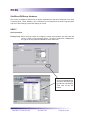
Part 1- Creating the LiNC-NET Database Folder
The default setting for the database folder is set to point to the c:\LNv5.11.2 Files folder (see
screen below).
If you need to change this setting (choosing another folder or creating a new one) follow the procedure below:
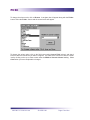
1. Go to Start\Programs\LNv5.11.2 and click on ConFigLN
2. In the Data-Base section, click on the Find folder... button. This will open the
Get Data Base Directory window (below).
3. In the Get Data Base Directory window, select the appropriate drive and/or
folder, click on File\New, and select Folder.
4. In the window, type in a name for your database folder (e.g. Files)
5. Click on the OK button to establish your new folder.
6. Click on File and select OK to return to the ConFigLN menu. The Data Base section will now reect C:\ProgramFiles\PCSC\LiNC-NET version 5.11.2\Files.
7. Click on the Write button in the top left side of the screen to save the new setting.
LiNC-NET 5.11.2 Admin Guide
38-10051-001
Page 39 of 264
PCSC
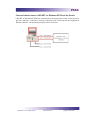
Option: Using a Shared Mapped Network Drive in a Multi-user System
(Host/Workstation/Concentrator)
This option allows you to map a drive (assign a letter to the folder and authorize any workstation
to see and access this folder like a physical drive). This option is specically used in a multi-user
environment.
If you are using a LINC-NET system with concentrators, you will also need to share
a drive
NOTE
When you select a share drive, the Find folder... is not used. The database
can be mapped to a drive anywhere in the network where sufcient disk
space can be allocated.
Sharing a Folder
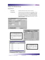
1. Check on the Use Shared Drive square. This will create a Share Drive... button.
2. Click on the Share Drive... button to see the contents of the folder.
3. If the content of the folder isn’t displayed in a full screen, click the square middle button on the
right top of the window menu so that it may enlarge to full-screen.
4. Go to View and click on Toolbar.
5. Click on the Up One Level icon to go
one level up in the directory.
LiNC-NET 5.11.2 Admin Guide
38-10051-001
Page 40 of 264
PCSC
6. Click on the folder name that has been chosen
during the Step 5: Part 1 conguration (in this
case, Files).
7. Right-Click on the folder to select (highlight) it
8. Go to the File option (located on the Title bar)
and click on Sharing.
9. In the Sharing tab select the Share As
option. The name of the folder will appear
in the Share Name windows. Type in your
selected le in the Share Name (in this case
Files)
10. Click on the Maximum Allowed button within
the User Limit section.
11. Click on Apply to conrm the share and OK
to exit from the sharing window.
12. A pop-up folder illustrating the contents of
the LiNC-NET 5.11.2 folder will appear. In
the folder window, go to File and click on
Explore.
LiNC-NET 5.11.2 Admin Guide
38-10051-001
Page 41 of 264
PCSC
13. Windows Explorer will appear. Click on
Tools and choose Map Network Drive.
14.
The Map Network Drive menu illustrates that the shared drive has been
chosen to be T. And that it is located on
the PC named HOST. The Files folder
contains the information (LiNC-NET data
les) that will be map\shared.
15. Click on the Close button and the Map
Network Drive menu closes (as do all of
the pop-up boxes) and the create database menu appears. Notice that the previously selected Shared Drive and Path
are now displayed within the Use Share
Drive window.
16. Click on the Write button to record the
designated Share Drive information to the PC’s hard disk drive.
Example If LnwFiles5.11.2 was the folder created and shared, the mapping with
the letter “T” should be like the screen below.
LiNC-NET 5.11.2 Admin Guide
38-10051-001
Page 42 of 264
PCSC
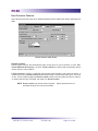
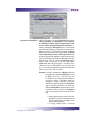
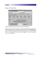
Part 2 - Conguring the Borland Database Engine (BDE)
This option is used to set the Borland Paradox database; the DBMS (Database Management
System) needed to run LiNC-NET for Windows.
1. Click on the BDE cong... button. The screen shown below will appear.
2. The NET DIR window displays the drive letter found in the BDEAdmin le. If this
drive letter is different from the one set in Mapping a Drive Letter for the Folder
section or in the Database Find folder eld (if sharing isn’t employed), the ...suggested button with the suggested drive letter will appear.
3. The NET DIR window must show the same drive letter set in Use Shared Drive
or the Database Find folder eld (if sharing isn’t employed). Click on the ...suggested button to change the conguration. If not using a shared drive, set to
C:\.
4. The BLOCK SIZE window allows you to change the size from 2048 (default
value) to 4096.
5. The LOCAL SHARE value must be set to TRUE regardless whether or NOT a
shared drive is employed.
6. As soon as all the parameters have been set, click on the Write button to save
these changes in the BDEAdmin le.
7. The Read button will read and display all settings found in the BDEAdmin.
8. Close the BDE conguration window by clicking on the Close button.
NOTE The next time the BDE cong... is pressed, the BDE conguration window will display the NET DIR, BLOCK SIZE and LOCAL
SHARE information. The ...suggested option will not be shown
because the NET DIR information is the same as the Use Shared
Drive setting.
LiNC-NET 5.11.2 Admin Guide
38-10051-001
Page 43 of 264
PCSC
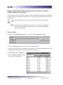
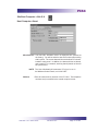
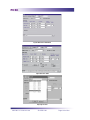
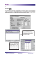
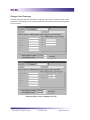
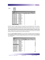
Part 3- Creating the LiNC-NET Database
Creating the database is simple. All you need to do is establish which panel you will be using with
your system.
In the ConFigLN Data Base section,
1. Click on the Create... button in ConFigLN. The Create Data Base screen will
appear. Notice that you are currently displaying the Main page.
2. Examine the 5 index tab folders. Click on the MicroLPMs tab. The MicroLPM
page shall appear.
MicroLPM Selection Field
LiNC-NET 5.11.2 Admin Guide
38-10051-001
Page 44 of 264
PCSC
NOTE If you are using a concentrator based system, the numbering system will be different. The rst digit will be based
off the particular concentrator and the three nal digits will
be based off the number of each panel (between 1 to 200).
Using this system, the rst number is 1001 (Concentrator
1 on Panel 1) and the highest number is 20200 (Concentrator 20 on Panel 200)
Example- Panel 122 on Concentrator 3 will be numbered 3112.
3. On the MicroLPMs page, select panel(s) for which data les will be created by
selecting the appropriate type from the uLPM model window.
NOTE The Scan button can be used to identify the panels currently dened in the database if no panels are dened an
error will be displayed. To recover click on the OK button.
4. To select panels individually, select the panel model in the radial button group
box, then select the panel number.
5. When you are nished selecting panels, click on the Default Values tab.
At this point, you are ready to start Part 4.
LiNC-NET 5.11.2 Admin Guide
38-10051-001
Page 45 of 264
PCSC
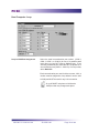
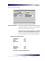
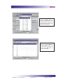
Part 4- Setting Up your Data Files
You can use ConFigLN: Create Data Base to set the basic characteristics of your system by
making adjustments in the Default Values page and in the Files page.
Follow the steps below to create the data les:
On the Default Values page, select the default values for:
Card Technology
Door Access Time
Card Table Format
Daylight Savings Dates
Entry/Exit
Enforcement Options
Use the explanations provided in following section to help you with your Default Values selections
Default Values Page
LiNC-NET 5.11.2 Admin Guide
38-10051-001
Page 46 of 264
PCSC
On the Files page, conrm that the proper les (all les initially) are selected for creation.
LiNC-NET 5.11.2 Admin Guide
38-10051-001
Page 47 of 264
PCSC
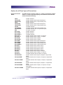
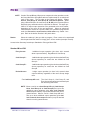
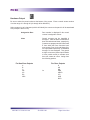
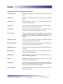
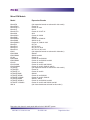
Create Data Base: Default Values: Card Technology
In this section, you must select the card reader technology that you will implement into your access
control system. Select the appropriate type of card reader in the Format window. The available
card technology formats are as follows:
ProTech
BR-350, BR-351, BR-370, BR-371, All Hughes ID Proximity Readers
MagStripe
BR-450, BR-451, BR-452, BR-470, BR-471
Watermark
Any Watermark card with the 12-digit format
PCSC Wiegand
34-bit PCSC Wiegand format, All Sensor Proximity Readers
Indala
Indala Proximity format
12-digit
No site code; Magnetic Stripe
Sensor 26
Standard Sensor 26-bit format
NOTE
BR-700 readers are setup as Sensor 26 Reader
FIRMWARE
Sensor 34
Standard Sensor 34-bit format
Special
Special format
PCSC 37
Special 37 bit HID Proximity format
Corp_1000
Special 35 bit HID Proximity format
Motorola 32
Special 32 bit Motorola Proximity format
A letter or additional reference description that describes the reader type can follow the
card technology:
PIN-Pad
PIN Pad with the reader.
(I)
Insert Reader
LiNC-NET 5.11.2 Admin Guide
38-10051-001
Page 48 of 264
PCSC
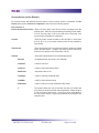
Create Data Base: Default Values: Door Lock Access Time
The Door Access Time is the length of time that the door lock is to be energized. The actual length
of time is 1/2 second less than the number of seconds specied. For example, access time value
of 1 denotes 1/2 second of access and time value of 5 denotes 4 1/2 seconds. Value of 1 is generally used for turnstiles.
You must select time values for both the Standard Access and Long Access
Standard Access is the normal door lock energize time. Select an access time from 1-253 seconds (2-253 seconds for elevator readers).
Long Access is the door lock energize time for cardholders that require a longer access time than
the standard access time(i.e. an individual with a disability). Select an access time from 2-254
seconds (3-254 seconds for elevator readers).
LiNC-NET 5.11.2 Admin Guide
38-10051-001
Page 49 of 264
PCSC
Create Data Base: Default Values: Card Table Format
Primary Expiration
Global- when selected the Primary expiration date is used for all cards at all readers wired to the panel. It is irrelevant whether the readers are parking,
building or department readers, as the secondary expiration date is not
used.
If you select Global, the system uses the Primary expiration date for all types of readers. In selecting Global, the PIN feature is automatically selected (and visa versa).
If you select Park-Only, each cardholder has 2 card expiration dates. One date controls the access
privilege for “parking” type readers and the other for all other types of readers. This unique function
allows the system administrator to automatically deny access to cardholders at parking readers,
yet allow them to pass through facility related readers.
PIN or Expiration Date (Parking Readers)
Park-Only when selected, the secondary expiration date is used for all cards but
only at parking readers wired to the panel. The primary expiration date
is then only used at department and building type readers.
If you select Park-Only as the primary expiration choice, you must select Date. If you select PIN,
you will have the capability of user-select 4-digit PIN codes. These PIN codes are used in conjunction with a combination reader and PIN Pad.
Names for Cardholders Exist
PCSC panel products have the ability to store the cardholder names within the panel itself. Selecting this option will decrease the number of cardholders in a standard MicroLPM panel from 1016 to
600 cardholders (IQ and SIM board capacity are unaffected by downloading names). If you require
names and more cardholders than 600, you will need to purchase a memory expansion kit from
the MicroLPM panel.
LiNC-NET 5.11.2 Admin Guide
38-10051-001
Page 50 of 264
PCSC
12-Digit Card Number
Various card formats are available within the system. When using the MagStripe or Watermark
format where a site code is not available, this option must be selected. For example, the MicroLPM
(and I.Q. and SIM) series supports 5 - 12 digit ABA Track 2 format data.
Create Data Base: Default Values: Daylight Savings
The Daylight savings cycle may be programmed into the panel.
Start: Enter the date of the ofcial start of Daylight Savings (In the U.S.- normally the rst Sunday
of April).
Stop: Enter the date of the ofcial end of Daylight Savings (In the U.S.- normally the last Sunday
of October).
NOTE If a MicroLPM panel does not roll into Daylight Savings (no Start date programmed), then it
won’t roll out of Daylight Savings (even if a Stop date was programmed). However, the IQ-7.9.12Q
or SIM 7.9.15S series rmware allows their respective boards to rollout of Daylight Savings, even
if they didn’t roll into it.
Create Data Base: Default Values: Entry/Exit Enforcement
Each panel supports three separate entry/exit enforcement levels: Strict, Lenient, and Soft. Each
enforcement level can be individually assigned to Parking, Department, or Building Type readers, but is enforced only when the Entry function and the corresponding Exit function readers are
on the same panel.
NOTE
Entry/Exit enforcement cannot be done (at any of the 3 levels) if the entry
readers are on one panel and the corresponding exit readers are on a different panel.
NOTE
These panel rmware versions require the door to be opened before
changing the card status, repeated accesses will be granted (regardless of
the anti-passback level of enforcement) if the door is not opened:
Standard MicroLPMPlus 2 MicroLPMPlus 4 MicroLPM-
Version 1.9.7 and above
Version 3.9.7 and above
Version 7.9.7
*All IQ and SIM panels require the door to be opened prior to updating the
card status.
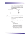
Strict Entry/Exit
The cardholder’s entry/exit status must be synchronized with the system, otherwise an entry/exit
error will be announced. In other words, the cardholder must have the proper status (building,
department, or parking) before he uses an entry/exit reader. The card status must be as follows:
LiNC-NET 5.11.2 Admin Guide
38-10051-001
Page 51 of 264
PCSC
If the cardholder’s Building Status is IN then Department Status can be IN or OUT.
If the cardholder’s building Status is OUT, the Department Status must be OUT.
If the cardholder’s Department Status is IN then Building Status must be IN.
If the cardholder’s status does not comply with the reader’s entry/exit denition,
then the system will deny access. In other words, when a cardholder attempts to
enter a Building IN reader, the cardholder’s building and department status must be
OUT.
Lenient Entry/Exit
This level is the same as Strict except on the rst use of the card, in which case the system will
automatically reset the building and department status to proper synchronization. The cardholder’s
second attempt at the reader will then grant him access.
Soft Entry/Exit
This level follows the same rules as Strict except that an error transaction is recorded, all status
levels are synchronized, and access is GRANTED.
Create Data Base: Files
On the Files page, select the les to be created, or press Select all.
Files Page
LiNC-NET 5.11.2 Admin Guide
38-10051-001
Page 52 of 264
PCSC
Create Data Base: Main
When you nish making your selections1. On the Main page, click on the Start button to begin creating the selected les.
2. When complete, click on the Exit button (located in the upper right hand corner) to exit the create
database module.
3. You will then return to the CongLN screen. Click on the Exit button located in the upper right
side of the screen to return to the desktop.
You are now ready to go to Step 6.
LiNC-NET 5.11.2 Admin Guide
38-10051-001
Page 53 of 264
PCSC
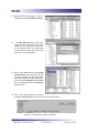
Step 6- Conguring your Panel(s) with ConFigUL
· Connecting to a Panel through a Direct Connection (RS-232
and RS-485)
· Connecting to a Panel through a LAN (Local Area Network)
· Changing a Panel’s Number
· Changing the Panel’s Password
· Changing the Direct Connection/MODEM Conguration
· Changing the Connection Baud Rate- MODEM/Direct
· Add/Change Panel Modem Telephone Numbers
· Logging Off from a Panel
· Exiting CongUL
ConFigUL ConFigUL was created by PCSC to set options
within each panel, such as the communications
Baud rate, password, address and Direct Connect/
AutoDial communications method.
LiNC-NET 5.11.2 Admin Guide
38-10051-001
Page 54 of 264
PCSC
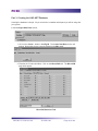
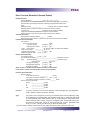
Connecting to a Panel through a Direct Connection
1. If the connection is Direct Connect, click on the Direct button.
Direct Connect
Baud Rate
2. Enter the port number (i.e. COM 1, COM 2, COM 3 or COM 4) that you are using for the Direct
connection and select the Baud rate (factory default is 4800).
3. Select the Open Port button. The display will expand to illustrate various conguration parameters.
Port Open
4. Check to see which Panel(s) are connected to the computer by selecting the Whose There
button. This will send a signal to every panel connected to the system at that time and request
a return signal.
5. In order to congure a panel, you must type the current number of the Panel connected to the
selected port (provided that you know what it is). Type the panel number that you want to congure (1 - 200) in the “Current Panel Number” block.
LiNC-NET 5.11.2 Admin Guide
38-10051-001
Page 55 of 264
PCSC
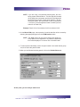
6. To conrm the number click on the Inquiry button. The system will conrm the current panel
number rst with a ‘-’ prex and display a ‘+’ prex if the number is correct.
Inquiry
Entry
In the example, the Inquiry reects a correct panel number entry (rst a ‘-’ prex)
and conrms the correct entry (with a ‘+’) prex.
Inquiry
Response
7. At this point, you need to type in the panel’s password. All panels are shipped from factory with
the default password PYMTF (It will be discussed later in this chapter how to change a panel’s
password). Type in the panel’s password and press the Logon button
At this point the panel is ready to be congured.
LiNC-NET 5.11.2 Admin Guide
38-10051-001
Page 56 of 264
PCSC
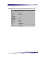
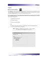
Connecting to a Panel(s) through a LAN connection
1. Click on LAN under Connection type.
2. Select the port number (2001 for Ultimate, 3001 for LANtronix or Black Box).
3. Check on Terminal serve (if you are using this kind of device) so the panel will interface the
network.
4. Type the IP address (see your network administrator, if you don’t know the IP address to set).
Click on the Open Port button. This screen will conrm the connection by displaying the IP
address, the port number, and then followed by:
CONNECTED
SEND READY
LiNC-NET 5.11.2 Admin Guide
38-10051-001
Page 57 of 264
PCSC
5. Check to see which panel(s) are connected to the computer by selecting the Whose There
button. This will send a signal to every panel connected the system at that time, and request a
return signal.
6. The rst entry required is the current number of the panel connected to the selected port. Type
the panel number that you want to connect to in the “Current Panel Number” block.
7. To conrm the number click on the Inquiry button. The system will conrm the current panel
number rst with a ‘-’ prex and display a ‘+’ prex if the number is correct. Inquiry reects a correct panel number entry (rst a ‘-’ prex) and conrms the correct entry (with a ‘+’ prex).
8. At this point, you need to type in the panel’s password. All panels are shipped from the factory
with the default password PYMTF (It will be discussed later in this chapter how to change a
panel’s password). Type in the panel’s password and press the Logon button.
At this point the panel is ready to be congured.
LiNC-NET 5.11.2 Admin Guide
38-10051-001
Page 58 of 264
PCSC
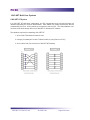
Changing a Panel’s Number
To change the current number of a controller or the default number (set in the factory), you must:
1. In the Current Panel Number window, type the present number (1-200) of the
panel.
2. In the New Panel Number, type the number (1-200) you want to assign.
3. Click on the Change Number button.
4. Under the Change Number, you will see two lines starting with ‘-‘ and ‘+’ followed
by this last line stating OK. This means that the panel has been modied successfully.
5. Click on the Restart button to implement the modication(s).
LiNC-NET 5.11.2 Admin Guide
38-10051-001
Page 59 of 264
PCSC
Changing the Panel’s Password
A default password of PYMTF is set for every panel at the factory. However, if you need to change
the password to a particular panel, it’s an easy process. Once you have logged onto a panel (using
its current password) you can change the panel’s password in a few simple steps.
1. In the Password box, delete the
current password.
2. Type in new password (a maximum of 8 characters). Be aware
that the password is case-sensitive.
3. Click on the Restart button to
implement the changes to the
panel.
NOTE Once you change a password from its default (PYMTF),
you must make the change in the MicroLPM Setup/
Features screen before it will communicate to the LiNCNET.
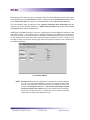
Changing the Direct Connection/MODEM Conguration
To the right of the ConFigUL port section is
the Comm port conguration section.
1. Click on the Get Current button. The panel
will display the panel’s current baud rate.
2. Click on the button next to Direct or Modem to change the connection conguration.
-If you are changing the connection to Direct and you using a RS-485 cable
between your panels and the Host computer, check the Multiport button to allow
different panels to share a common communications channel (Multidrop Protocol).
-If you are changing the connection to Modem, a Telephone numbers section will
appear in the Comm port conguration square.
3. Click on the Update button to implement the changes to Comm Port conguration.
LiNC-NET 5.11.2 Admin Guide
38-10051-001
Page 60 of 264
PCSC
Changing the Connection Baud Rate- Modem/Direct
You may nd it necessary to change the Baud Rate connection between the host and the panels
in either a Modem or Direct connection. The default baud rate is 9600, however sometimes
modem congurations differ or communication is smoother at a slower rate (i.e. when telephone
lines experience induced noise due to bad weather conditions).
1. Click on the Get Current button. The panel will display the panel’s current baud
rate.
2. Click on the pull-down screen and select the appropriate baud rate.
3. Click on the Update button to implement the changes to the panel’s baud rate.
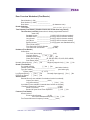
Add/Change Panel-Modem Telephone Numbers
If you have changed the Comm Port Conguration or need to update the telephone number that
the panel would dial to the Host computer, you can make changes in the Telephone Numbers
section.
Get Button
1. Click on the Get button
for Telephone #1 to conrm the phone number currently being used as the
primary modem phone
number.
2. If necessary, change the
number in the Telephone
#1 box.
3. Click on the Change button
to implement the changes
to the panel’s primary
modem
telephone
number.
Change Button
4. If necessary, repeat Steps 1-3 for Telephone #2.
LiNC-NET 5.11.2 Admin Guide
38-10051-001
Page 61 of 264
PCSC
Logging Off from a Panel
Once you have made all the conguration changes necessary to the
panel, remember to Logoff the panel.
Though the panel will eventually
Logoff by itself via a timer, you will
eliminate any communication complications by logging off properly.
Exiting ConFigUL
At the end of your session with ConFigUL, click on the Close Port button,
which ceases your connection to the
panels and exits the Conguration
Menu. You may exit ConFigUL or
reestablish a connection using a different connection type (Direct or LAN).
LiNC-NET 5.11.2 Admin Guide
38-10051-001
Page 62 of 264
PCSC
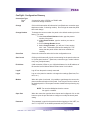
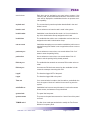
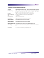
ConFigUL- Conguration Glossary
Connection Type:
Direct
LAN
A connection using a RS232 or a RS485 cable
Connection through a network
Change
Click on this button when all information is set (Baud rate, connection type,
telephone number, if choosing modem). Do not forget to restart the panel
after each change.
Change Number
To change the current number of a panel or the default number (set in the
factory), you must:
1. In the Current Panel Number window, type the present
number of the panel.
2. In New Panel Number, type the number you want to
assign.
3. Click on Change Number button.
4. Under Change Number, you will see 2 lines starting
with ‘-’ and ‘+’ followed by this last line stating OK. This
means that the panel number has been modied successfully.
Close Port
Closes the connection and exits from the conguration menu.
Get Current
Clicking on this button will give the current setting for the panel number set
in “Current panel number”: (Baud rate, connection type, modem information [if set], multipoint state).
IP Address
(LAN connection) Refer to your LAN administrator for the IP address of
the terminal server/Ultimate MicroLPM and enter it in this block.
Logoff
Log off from the panel currently connected.
Logon
Log on to the panel to examine or change other settings (Baud rate, Protocol, etc.)
Modem
When this option is selected, it is possible to get/change the current telephone numbers already set in the panel. Don’t forget to set the number of
the desired panel in Current panel number window before performing any
change.
NOTE Do not select Multipoint when the connection type is a modem!
Open Port
When the connection type has been chosen and congured, click on this
button to open the port and start to congure or modify the actual panel
setting.
Password
This password is used for the panel and when logging on LiNC-NET, version 5.11.2 (PYMTF is the default password set by the Factory).
LiNC-NET 5.11.2 Admin Guide
38-10051-001
Page 63 of 264
PCSC
Port
Allows you to select your COM port (Com 1, Com 2, Com 3, Com 4-13,
etc.).
Restart
Restart the panel to implement all the information set for the current
panel.
Terminal Server
(LAN Connection) Terminal Servers convert serial communication protocols to TCP/IP Ethernet protocol. Click on this option if you are using this
type of device.
Who’s There
Allows you to look from panel 1 to 200 and is used for identifying which
panels are connected. The scroll menu on the left side of the Whose
There button lists all the panel numbers found during this task. All panel
numbers on the port chosen (whether by Direct daisy chain or LAN) will be
listed below under Who’s There, too.
LiNC-NET 5.11.2 Admin Guide
38-10051-001
Page 64 of 264
PCSC
Step 7- Using LiNC-NET
RememberIn a Multi-User or Concentrator system, PC’s must be
booted up in the following order:
1. Host PC
2. Concentrator PC(s)
3. Workstation PC(s)
Booting up the system in a different order could cause network communication problems.
Also, in a Mullti-User or Concentrator system, PCs must be
shut down in the following order:
1. Workstation PC(s)
2. Concentrator PC(s)
3. Host PC
Shutting down the system in a different order could cause
network communications problems
LiNC-NET 5.11.2 Admin Guide
38-10051-001
Page 65 of 264
PCSC
Part 1- Coming and Going
Starting LiNC-NET
1. In Windows, press Start at the bottom of the screen. The menu will display a list of programs.
Click on Programs and then click on LNv5.11.2.
2. Double-click on the LiNC_NET icon and the password menu will appear.
3. Enter 0 and then the password PYMTF to sign on to LiNC-NET. The System menu will appear.
NOTE If you have installed a client database, enter the name of the client before
entering a password.
4. Click the Password icon or click on the Password heading.
5. Create your exit password for exiting LiNC-NET. Modify or enter new passwords for accessing
each level (Exit, Switching Menus, etc.). The Password menu and the System setup will be
described in following sections.
Exiting LiNC-NET
From the System Commands menu, press the Log Off icon to sign off LiNC-NET.
The Sign-on screen will appear. Enter your ID number and then the Exit password to terminate
LiNC-NET.
NOTE In the course of setting up your system, a password system is installed
that will allow varying levels of access to LiNC-NET NT/95. There will be
both an access password and an exiting password.
To prevent data loss or corruption of the database while LiNC-NET is running, you MUST use your Exit password. DO NOT use a warm boot
(CTRL-ALT-DEL) or a cold boot (Power switch off) to terminate the LiNCNET application software.
LiNC-NET 5.11.2 Admin Guide
38-10051-001
Page 66 of 264
PCSC
Part 2- System Commands and Menus
System Menu
User Menu
A section of the LiNC-NET program that is used by the LiNC-NET
Systems Administrators to establish the basic system parameters of LiNC-NET. The System Menu also gives access to features such the Password Menu, which are restricted from the
User Menu.
A section of the LiNC-NET program that is used by the normal operators of the LiNC-NET System. The User Menu functions for the
day-to-day use of the LiNC-NET system, including activating and
reactivating cards and establishing time periods and holidays. For
a detailed description of the User Menu, please see the LiNCNET 5.11.2 for Windows User Guide (Part# 37-10050-001).
The following steps outline the procedure to set up the system. Items 4 and 7 are dened in the
User Menu.
1. Initialize the panels to user-selected default values. See Bulk initialization.
2. Congure the panels that vary from the default set in Step 1. See Site-MicroLPM
conguration.
3. Congure the communication ports at the Host. See Site-Host conguration.
4. Select Request on-line for those panels that need to be on-line. See MicroLPM
On-line.
5. Dene doors and readers. See Door Overview.
6. Add cards. See Card (Add Card).
7. Dene card authorization groups and time periods. See Card Authgroup.
System Commands
This chapter provides an overview of the System Commands Menu. The System Commands
Menu is displayed after LiNC-NET is started from Windows-NT/98 and the Password has been
entered. From the System Commands Menu all features and functions are accessible. After
selecting a menu item, a set of options will be displayed. You can use either the mouse or keyboard command to initiate the function you wish to access.
LiNC-NET 5.11.2 Admin Guide
38-10051-001
Page 67 of 264
PCSC
The System Commands Menu and Tool Bar
The System Commands Menu is comprised of the following main menu items:
Bulk
Used for bulk initialization of data, including: card technology, access times, the date and time input format,
card database format, and entry/exit options.
Site
Allows the administrator to congure the hardware
(Host Computer) and system parameters for each
panel. This menu also provides useful information
for easy identication of a specic panel. Some of
this data is not required for system operation and
is entered for information purposes only. The panel
model number identication, hardware options, entry/
exit enforcement, and expiration dates for cards can
be entered in this menu.
Door Overview
Congures door parameters such as card technology,
access time, auto-unlock time, and two-person minimum occupancy rule. Access Actions: Dene what
(if any) action should automatically turn on or off, and
program counter time outputs.
NOTE Familiarity with the panel functions is required to implement
this function.
HardwareInput
Congure sense input number, name to door number
and assign the type of alarm, door sense, input counter, etc. Also, set the input polarity. Dene the counter actions which will automatically occur when input
transitions from state-to-state (Normal/Closed, Alarm/
Ajar, Trouble /Forced), i.e., link the inputs to the outputs.
Hardware-Output
Name and dene outputs and set their functions. These
parameters determine when to turn on and off, as well
as dene the actions when entering and exiting time
periods.
Elevator-ELV
Controls the destination of an elevator cab based on a
card’s authorization attributes. When a card is swiped
at a reader inside a cab, the time period/oor group
pairs assigned to the card are evaluated to determine
which relays the card can activate at the current time.
Of those relays, the ones that are assigned to the
reader used are activated to engage the oor buttons
from which the cardholder can make a selection
LiNC-NET 5.11.2 Admin Guide
38-10051-001
Page 68 of 264
PCSC
CardAdd Card & Change Card
LiNC-ID
IntegrityUpload
IntegrityBackup
The Card menu denes the cardholder data. All
options and here. Each card can be assigned with
the following information: cardholder name, normal
or long access, override capability with event lockout
and access costs, escort status, entry/exit exemption,
card group specication, afliation, counter number
class, PIN, authorization group, and expiration dates.
Cards may be added or changed individually or in a
group (bulk).
Refer to LiNC-NET manual P/N 33-10038-001
Upload is the converse of download. In other words,
data from the panel is transferred to the hard drive of
the LiNC-NET host. Files can be individually or collectively selected for uploading.
Only History les will be backed up to the selected
drive.
Password
Each password is dened with access privileges that
determine which functions are available to an operator. The initial system password is PYMTF. In addition to passwords and ID levels, class levels (None,
System, User, Exit, and switch) can be designated for
each operator.
Program Levels
In addition to passwords, program levels within the
main access options (System, User, and Switch
[System and User]) can be designated for each
operator.
Alarms
LiNC-NET supports 2 types of alarms: 1) Sense
Input and 2) Transaction. Sense input alarms are
physical inputs driven by alarm devices, such as magnetic contacts and glass break and passive infrared
detectors. Transaction alarms are created by historical transactions, such as an access denied, a disk
error, a Logon occurrence, etc.
LiNC-NET 5.11.2 Admin Guide
38-10051-001
Page 69 of 264
PCSC
Alarm Acknowledgment
An alarm record may be dened at the Host by
assigning a panel sense input record to a Host alarm
record. When an alarm is detected at the panel, it
can cause the corresponding alarm at the Host to be
set and to log an alarm event to the journal le. An
alarm condition at the Host/Workstation causes the
alarm icon at the top of the screen to ash red-white
and activates a break out box to acknowledge the
alarms.
Logger
LiNC-NET maintains a logger (history) le comprised
of records transferred from various panels. History
records may be transferred (uploaded) upon the
operator’s request. The on-screen real-time journal
appears when the “blue” button at the top of the
screen is clicked on, and continues to scroll upward
as transactions occur at the panels and readers. The
logger records the following information: The PC host
number (unless the system is a stand-alone unit), the
panel number, the alarm status, the date and time
logged, the date and time of occurrence, the name
and location of where the transaction took place, and
a code reference.
Reports
LiNC-NET is capable of producing reports to the
screen or printer. The report setup window contains
a tabbed notebook. The Display page allows the
user to select the elds to be included in the report
and the Search page allows the user to specify the
search criteria. The Display page also contains buttons under Change Heading that allow the user to
alter the heading and the column widths of the elds.
Refer to User Guide.
User (Switch)
This allows you to switch from the System Commands menu to the User menu. The sign on password must have the Switch class selected.
Logoff
Logoff allows you to sign-off from LiNC-NET for
Windows-NT/95/98 and return to Password entry.
Help
This screen assists in the data entry process and
denes the criteria required for proper operation.
LiNC-NET 5.11.2 Admin Guide
38-10051-001
Page 70 of 264
PCSC
Data Entry and Modication
To display or make modications to the LiNC-NET for Windows-NT/95/98 database, follow these
instructions:
1. Enter a le selection. (Example: Site). Key letters are underlined in each le
name. Press Alt-S to access Site les. The sub-menu listing displays Host and
MicroLPM. Tab or arrow key to your selection. Press Enter. Or click on the
selection or the icon with the mouse button.
2. Click on to the block that you wish to modify using the mouse or use the Tab key
from the keyboard.
3. Position the cursor at the data eld that you wish to modify or add to, and highlight the eld by clicking on the block. A range window, described below, will
appear on the screen for those elds that offer multiple options.
4. A data eld can be modied in one of the following ways:
a) Some elds require only a Yes/No conrmation. These are
denoted by a [ ] for No and a [x] for Yes. Highlight the bracket
area using the mouse or Tab key and click On or press Enter to
conrm the selection.
b) Some elds will display a list of options available for that eld.
Highlight the appropriate selection by clicking on the [ ? ] button
or scroll through the selections using the cursor control keys
(arrow).
c) Some elds require that the operator enter the data. (Example:
the name eld). Enter the data then press the mouse button or
the Tab key to advance.
d) Other elds will have a navigator bar, shown below, which will
appear at the top of the le.
a. Set the current record to the rst record.
b. Set the current record to the previous record.
c. Set the current record to the next record.
d. Set the current record to the last record.
e. Add a new record.
f. Delete the current record.
g. Put the dataset in Edit state so that the current record
can be modied.
h. Write changes to the current record to the database.
i. Cancel edits to the current record.
j. Refresh the current record display.
All record elds (System and User) contain the legal keyboard character input.
LiNC-NET 5.11.2 Admin Guide
38-10051-001
Page 71 of 264
PCSC
Bulk Initialization
LiNC-NET enables the user to initialize every panel in the system to user-selected default values.
Bulk Initialization denes the card technology; access times, the date and time input format, daylight savings parameters, card database format, and entry/exit options.
If you have just installed LiNC-NET using ConFigLN, then you will notice that the Bulk Initialization page is almost exactly the same as the Create Data Base: Default Values page. You will also
notice that the entries made in the Create Data Base: Default Values page will appear here in the
Bulk Initialization page.
Making Changes in Bulk Initialization
Select All Fields
This button selects all data elds. All elds will be displayed in bold.
Deselect All Fields
This button clears the selection for all data elds. All elds
will be displayed in gray.
Select a Single Entry
Right-click on eld to be changed. The eld will be highlighted in bold.
Start Bulk Change of All Panels
(Selected Felds)
This button starts the update of the elected elds for each
panel.
To initialize all panels:
1. For each group of data to be initialized, select the group by clicking the mouse on
the group name or within the group box not occupied by any eld, then enter the
value for the data eld(s) in the group.
2. Select the Start Bulk Change of All Panels (Selected Fields) button.
LiNC-NET 5.11.2 Admin Guide
38-10051-001
Page 72 of 264
PCSC
Bulk Initialization: Card Technology
In this section, you must select the card reader technology that you will implement into your access
control system. Select the appropriate type of card reader in the Format window.
The available card technology formats are as follows:
ProTech
BR-350, BR-351, BR-352, BR-370, BR-371, All Hughes ID
Proximity Readers
MagStripe
BR-450, BR-451, BR-452, BR-470, BR-471
Watermark
Any Watermark card with the 12-digit format
PCSC Wiegand
34-bit PCSC Wiegand format, All Sensor Proximity Readers
Indala
Indala Proximity format
12-Digit
No site code; Magnetic Stripe
Sensor 26
Standard Sensor 26-bit format
NOTE BR-700 readers are setup as sensor 26 readers.
Sensor 34
Standard Sensor 34-bit format
Special
Special format
PCSC 37
Corp_1000
Motorola 32
Special 37-bit HID Proximity format
Special 35-bit HID Proximity format
Special 32-bit motorola Proximity format
A letter or additional reference description that describes the reader type can follow the
card technology:
PIN-Pad
(I)
LiNC-NET 5.11.2 Admin Guide
PIN Pad with the reader.
Insert Reader
38-10051-001
Page 73 of 264
PCSC
Bulk Initialization: Door Lock Access Time
The Door Access Time is the length of time that the door lock is to be energized. The actual length
of time is 1/2 second less than the number of seconds specied. For example, access time value of
1 denotes 1/2 second of access and time value of 5 denotes 4 1/2 seconds. Value of 1 is generally
used for turnstiles.
You must select time values for both the Standard Access and Long Access
1. Standard Access is the normal door lock energize time. Select an access time
from 1-253 seconds (2-253 seconds for elevator readers).
2. Long Access is the door lock energize time for cardholders that require a longer
access time (i.e. an individual with a disability). Select an access time from
2-254 seconds (3-254 seconds for elevator readers).
Bulk Initialization: Card Table Format
Primary Expiration
If you select Global, the system automatically selects the Primary expiration date for all types of
readers. You must select Global, if user-select PIN is to be used.
If you select Park-Only (then the expiration date (parking readers) is set to Date automatically),
each cardholder has 2 card expiration dates. One date controls the access privilege for “parking”
type readers and the other for all other types of readers. This unique function allows the system
administrator to automatically deny access to cardholders at parking readers, yet allow them to
pass through facility related readers.
PIN or Expiration Date (Parking Readers)
If you select Park-Only as the primary expiration choice the system automatically selects Date. If
you select PIN (only available when primary expiration is set to Global), you will have the capability
of user-select 4-digit PIN codes. These PIN codes are used in conjunction with a reader and PIN
Pad.
Names for Cardholders Exist
PCSC panel products have the ability to store the cardholder names within the panel itself. Selecting this option will decrease the number of cardholders in a standard MicroLPM 1016 to 600
cardholders (the capacity of the IQ/SIM panels are not effected by downloading). If you require
names and more cardholders than 600, you will need to purchase a memory expansion kit for the
MicroLPM.
12-Digit Card Number
Various card formats are available within the system. When using the MagStripe or Watermark
format where a site code is not available, this option must be selected. The panel series supports
8 - 12 digit ABA Track 2 format data
LiNC-NET 5.11.2 Admin Guide
38-10051-001
Page 74 of 264
PCSC
Bulk Initialization: Daylight Savings
The Daylight Savings Cycle may be programmed into the panel.
Start
Enter the date of the ofcial start of Daylight Savings (In the U.S.- usually
the rst Sunday of April).
Stop
Enter the date of the ofcial end of Daylight Savings (In the U.S.- usually
the last Sunday of October).
NOTES
If the panel does not roll into Daylight Savings (no
Start date programmed), then it won’t roll out of Daylight Savings (even if a Stop date was programmed).
For IQ-200 with IQ 7.9.12Q (or newer) rmware or
SIM with SI-7.9.15S (or newer) rmware. The panel
will automatically roll out of Daylight Savings Time
even if it didn’t roll into Daylight Savings Time.
Bulk Initialization: Entry/Exit Enforcement
Each panel supports three separate entry/exit enforcement levels: Strict, Lenient, and Soft. Each
enforcement level can be individually assigned to Parking, Department, or Building Type readers,
but is enforced only when the Entry function and the corresponding Exit function readers are on
the same panel.
NOTES
Entry/Exit enforcement cannot be done (at any of the 3 levels) if the
entry readers are on one panel and the corresponding exit readers
are on a different panel.
These panel rmware versions require the door to be opened before
changing the card status, repeated accesses will be granted (regardless of the anti-passback level of enforcement) if the door is not
opened:
Standard MicroLPMPlus 2 MicroLPMPlus 4 MicroLPM-
Version 1.9.7 and above
Version 3.9.7 and above
Version 7.9.7
All IQ and SIM panels require that the door be opened prior to updating the card status.
Strict Entry/Exit
The cardholder’s entry/exit status must be in synchronized with the system, otherwise an entry/exit
error will be announced. In other words, the cardholder must have the proper status (building,
department, or parking) before he uses an entry/exit reader. The card status must be as follows:
LiNC-NET 5.11.2 Admin Guide
38-10051-001
Page 75 of 264
PCSC
If the cardholder’s Building Status is IN then Department Status can be IN or OUT.
If the cardholder’s Building Status is OUT, the Department Status must be OUT.
If the cardholder’s Department Status is IN then Building Status must be IN.
If the cardholder’s status does not comply with the reader’s entry/exit denition,
then the system will deny access. In other words, when a cardholder attempts to
enter a building IN reader, the cardholder’s building and department status must be
OUT.
Lenient Entry/Exit
This level is the same as Strict except on the rst use of the card, in which case the system
will automatically reset the building and department status to proper synchronization. The
cardholder’s second attempt at the reader will then grant him access.
Soft Entry/Exit
This level follows the same rules as Strict except that an error transaction is recorded, all
status levels are synchronized, and access is GRANTED.
LiNC-NET 5.11.2 Admin Guide
38-10051-001
Page 76 of 264
PCSC
Site/Host Computer- <Alt>S, H
Host Computer: About
Miscellaneous The LiNC-NET Windows version is displayed here (entered at
the factory). You will be asked to state this number when calling
with inquiries. The current date and time at the Host PC is downloaded to each panel. In addition, the date and time are broadcast to each PC in a network, ensuring that all panels on-line will
be synchronized.
NOTE The Host /Workstation/Concentrator PC’s time is set in
the Windows Control Panel, not in LiNC-NET.
Address
Enter the street and city location of the PC Host. Two telephone
numbers may be entered for the central computer center.
LiNC-NET 5.11.2 Admin Guide
38-10051-001
Page 77 of 264
PCSC
Host Computer: Loop
Loop to COM Port Assignment
Select the serial communication port number (COM 1,
COM 2, COM 3, or COM 4) for one of 4 possible panel
loops when you are NOT using a Stallion® port. If you
are using a Stallion® port, then LiNC-NET is capable of 13
communication ports (COM 1 – COM 13). If no loop exists,
select NotInUse.
Each communication port used for direct connect, LAN, or
modem must be assigned to a loop before it can be used.
A COM port MUST be used for any LAN connection.
A Log Off MUST take place to initialize the
COM port after any changes take place.
LiNC-NET 5.11.2 Admin Guide
38-10051-001
Page 78 of 264
PCSC
Modem Dial Out
A single AutoDial modem (e.g., U.S. Robotics Sportster
14.4 or 28.8/33.6/56k Fax-Modem) may be used at the PC
for dial out to any of the panels in the LiNC-NET system.
Consult factory for other compatible modems.
Select the port where the modem for auto-dial panels
is connected. This COM port number must be different
than the direct connect COM port number. If no auto-dial
modem is being used, select NotInUse.
The COM port selected for this eld must have the type of
connection eld set to modem.
For further information, refer to Modem Restoration after
Power Loss Technical Bulletin 39-10052-001.
Port Conguration
For the four possible COM port number congurations:
1. Make a selection in the Type of connection
window (i.e., NotInUse, Direct, MODEM,
LAN)
2. Make a selection in the BAUD rate window (i.e.
1200, 2400, 4800, 9600)
NOTE While LiNC-NET can support
baud rates up to 256 kbps, the
panels only communicate at
speeds of 1200, 2400, 4800 or
9600 bps.
3. If you have a MODEM installation, select
the Telephone number (incoming) of the PC
Host MODEM that will communicate with the
panel.
4. Dene the speed of the data transfer from the
panel to the PC Host (the default rate is 9600
Baud). The system provides for 1200, 2400,
and 4800, in addition to the 9600 rate. The
phone number (incoming) of the Host must be
entered here.
NOTE The speed of the PC modem
MUST be compatible with the
panel’s auto-dial modem.
LiNC-NET 5.11.2 Admin Guide
38-10051-001
Page 79 of 264
PCSC
Changing Baud Rate or Port Type:
1. If you are currently in Direct Connect mode, and wish to change the Baud rate ONLY:
a) Ensure that all panels are currently On Line.
b) If changes are required, click on Host Computer Loop/Port tab. (See Host
Computer Setup). Make change(s) in menu.
c) Click on the check button to write changes to the hard disk.
d) Press Log off to access the Sign On password screen (do NOT exit from LiNCNET for Windows-NT/95/98).
e) Enter the Log On password (NOT exit password) and you are back to the
System Menu. The connection will be re-established automatically and the new
Baud rate will be set.
NOTE If Baud rate was altered and the panel was not on-line,
either alter it back to original setting or modify the panel’s
DIP switch conguration (for more information, see your
panel’s Installation Manual).
LiNC-NET 5.11.2 Admin Guide
38-10051-001
Page 80 of 264
PCSC
2. If you are currently in MODEM (auto dial) mode, and wish to change the Baud rate ONLY:
!Important!
Baud rate changes should be made in a separate
session. Do NOT combine this change with other
downloading, which may cause the panel to
restart.
a) If changes are required, click on Host Computer Loop/Port tab. (See Host
Computer Setup).
b) Make Baud Rate change(s) in menu.
c) Click on the ‘check’ [3] button to write changes to the hard drive.
d) Repeat the following for all panels in the system:
i. Dial the panel and hang up by requesting Ofine. (At this time,
the user can still dial the panel or the panel can dial the Host
and communicate at the original Baud rate).
ii. Continue this procedure until all the panels are dialed.
e) Press Log off to access Log Off password screen (do NOT exit from LiNC-NET
for Windows-NT/95/98).
f) Enter password (NOT exit password) and you are back to the System Menu.
This will restart (warm boot) all affected panels.
LiNC-NET 5.11.2 Admin Guide
38-10051-001
Page 81 of 264
PCSC
3. If you are currently in Direct Connect mode, and wish to change the Port type to AutoDial
ONLY:
a) Ensure that all panels are currently On Line.
b) If changes are required, click on Host Computer Loop/Port tab. (See Host
Computer Setup).
c) Make Type of Connection change(s) in the menu.
d) Click on the check button to write changes to the hard drive.
e) Press Log Off.
f) For all affected MicroLPMs, on the panel PCB, change the RS-232/RS-485
jumper and DIP switch to let location 04 =8.X
NOTE X depends on Baud Rate:
e.g. 8.8 for 9600 baud
8.2 for 2400 baud
For more information, see your MicroLPM Installation
Manual- P/N 33-10019-001. For IQ and SIM panels,
consult your panel’s installation manual:
-IQ Installations Manual (P/N: 33-10036-001
-SIM Installations Manual (P/N: 33-10037-001
g) Exchange your direct connecting cable to a modem cable.
LiNC-NET 5.11.2 Admin Guide
38-10051-001
Page 82 of 264
PCSC
4. If you are currently in MODEM (auto dial) mode, and wish to change the Port type to Direct
Connect ONLY:
!Important!!
Baud rate changes should be made in a separate session. Do NOT combine this change with
other downloading, which may cause the panel to
restart.
a) If changes are required, click on Host Computer Loop/Port tab. (See Host
Computer Setup).
b) Make Type of Connection change(s) in menu.
c) Press Log off.
d) For all affected MicroLPM’s, on the panel PCB, change the RS-232/RS-485
jumper and DIP switch to let location 04 =8.X
NOTE
X depends on Baud Rate:
e.g. 8.8 for 9600 baud
8.2 for 2400 baud
For more information, see your MicroLPM Installation
Manual- P/N 33-10019-001. For IQ and SIM panels, consult your panel’s installation manual:
-IQ Installations Manual (P/N: 33-10036-001
-SIM Installations Manual (P/N: 33-10037-001
e) Exchange your direct connecting cable to a MODEM cable.
LiNC-NET 5.11.2 Admin Guide
38-10051-001
Page 83 of 264
PCSC
5. If you are currently in LAN mode, and wish to change the IP address type ONLY
a) If you wish to change the IP address, click on the MicroLPM Setup Hardware
tab.
b) Under LAN connection, highlight the current address in the IP Address block
c) Enter the new address.
d) Consult with your LAN administrator or MIS personnel to ensure the correct
address (when using a LAN connection, make sure that the terminal server is
connected to the panel).
e) Click on the “check” box at the top left side of the menu to save the new
address.
f) Press Log off.
LiNC-NET 5.11.2 Admin Guide
38-10051-001
Page 84 of 264
PCSC
Host Computer: Port
Port Conguration
This section should display the com ports that have been congured in
ConFigUL. There are four screens displaying COM ports 1 – 13
Type of Connection
-Direct (Direct Connect RS232/RS485 type)
-Modem (Autodial up connection)
-LAN [Local Area Network through an Ethernet (NIC) Network Interface
card
-NotInUse (if the com port is not utilized by the LiNC-NET)
Baud Rate
1200, 2400, 4800, 9600, 14k, 19k, 38k, 56k, 57k, 115k, 128k, 256k
Telephone Number
Phone # of modem installed at LiNC-NET Host PC
MODEM intialization AT (Attention) commands used to train an external MODEM connected to
a COM Port.
LiNC-NET 5.11.2 Admin Guide
38-10051-001
Page 85 of 264
PCSC
Adding or Deleting a Panel
The data bases for panels are added to and deleted from the database as necessary.
Current Count This le indicates how many panels are currently part of your system. To add or
delete a module, enter the number of the panel and click on the arrow button to
select the model type. Press Add MicroLPM or Delete MicroLPM.
Up to 200 panels may be added. When adding a new panel into LiNC-NET all the
information from the Bulk Initialization page will automatically default to the new
panel.
LiNC-NET 5.11.2 Admin Guide
38-10051-001
Page 86 of 264
PCSC
Site/MicroLPM
Site/MicroLPM: Features
Password
The default password PYMTF (set at factory) is used to logon the panel during the initial set-up.
It is recommended that once communication is established with the panel (on-line), the password
should be changed. Since PYMTF is used for initial set-up, you must use PYMTF to logon, each
time a new panel is added to the system.
Daylight Savings
The Daylight Savings cycle may be programmed into the panel.
Enter
Enter the date of the ofcial start of Daylight Savings. In the US, it the
rst Sunday in April. Enter the date that daylight savings begins in month,
day, year format (e.g., 04/04/99).
Exit
Enter the date of the ofcial end of Daylight Savings. In the US, it is the
last Sunday in October. Enter the ending date in the same format (e.g.
10/24/99).
NOTE So that LiNC-NET will be Y2K compliant, the PC must
be congured for a 4-digit year format. Consult the Windows® Control Panel/Regional Settings and select the
Short Date format of mm/dd/yyyy and the Long Date
format of mm/dd/yyyy to accommodate the LiNC-NET
for uninterrupted (proper) operation.
LiNC-NET 5.11.2 Admin Guide
38-10051-001
Page 87 of 264
PCSC
Entry/Exit Enforcement
Each panel supports 3 separate levels of Entry/Exit enforcement: Strict, Lenient, and Soft. Each
enforcement level can be assigned individually by Parking, Department, or Building-type readers, but is enforced only when the Entry function and its corresponding Exit function reader(s) are
on the same panel. Entry/Exit Enforcement cannot function (at any of the 3 levels) if the Entry
reader(s) are on one panel and the corresponding Exit readers are on another panel.
NOTE Version 1.9.7 and above for Standard MicroLPMs
Version 3.9.7 and above for Plus 2 MicroLPMs
Version 7.9.7 for Plus 4 MicroLPMs
These rmware versions require the door be opened
before charging the card status, repeated accesses will be
granted (regardless of the anti-passback level of enforcement) if the door is not opened.
NOTE All IQ and SIM Panels require that the door be opened
prior to updating the card status
Strict Entry/Exit
The cardholder’s entry/exit status must be synchronized with the system, otherwise an entry/exit
error will be announced. In other words, the cardholder must have the proper status (building,
department, and parking) before he uses an entry/exit reader. The card status must be as follows:
If the cardholder’s Building Status is IN, then the Department Status must be
OUT or IN.
If the cardholder’s Building Status is OUT, then the Department Status must be
OUT.
If the cardholder’s Department Status is IN, then the Building Status must be
IN.
If the cardholder’s status does not comply with the reader’s entry/exit denition,
then the system will deny access. In other words, when a cardholder attempts to
enter a building IN reader, the cardholder building and department status must be
OUT.
Lenient Entry/Exit
This is the same as Strict except on the rst use of the card; the system will automatically reset the
building and department status to proper synchronization. The cardholder’s second attempt at the
reader will then grant him accesses.
Soft Entry/Exit
Same as strict except that an error transaction is recorded, statuses are synchronized, and access
is GRANTED.
LiNC-NET 5.11.2 Admin Guide
38-10051-001
Page 88 of 264
PCSC
In Case of LockIn/LockOut
To restore operation to a card whose owner has been locked in or out due to an entry/exit (antipassback) violation, simply deactivate and then re-activate the card from the Change Card screen
with the panel(s) online.
NOTES
Depending on the MicroLPM rmware version, when toggling status for
In/Out of doors, either an Authorized card or an Authorized card followed
by a door open activation, will toggle In/Out status.
MicroLPM Firmware versions 1.9.7 and 7.9.7 or higher provide for an
Authorized card followed by a Door Open to toggle In/Out status.
MicroLPM versions 1.96, 3.96, 5.96, or 7.96 or lower provides for an
Authorized card ONLY to toggle In/Out status.
All IQ and SIM panels require that the door be opened prior to updating
the card status.
LiNC-NET 5.11.2 Admin Guide
38-10051-001
Page 89 of 264
PCSC
Card Table Format
Primary Expiration (Park/Global
Panels support parking, department, and building
type readers. The system can automatically expire
a card for Parking Only readers, if the PARKONLY is selected. Click on the options:
-Park-Only
Selects a secondary card expiration date to be
used at parking-type readers.
-Global
Selects a primary card expiration date to be used
at all readers
PIN or Expiration Date (Parking Readers)
Because there is a limitation of cardholder space
in RAM in the panel, the Global expiration date
automatically selects the PIN option. Conversely,
selection of the Park-only option selects the date
option.
Names for Cardholders Exist
The cardholder le within the standard MicroLPM
panel can be congured with or without names.
If the panel is congured with names, it requires
more memory space and lowers the card capacity.
However, All “Plus” series MicroLPMs default to
cards with names. For IQ and SIM panels, downloading names has no bearing on card capacity
Select “X” if names for cardholders exist in the
system. If this section is changed, System Parameters and Cards les must be downloaded to the
panel in order for the changes to take effect.
12-Digit Card Numbers
If this section is changed, System Parameters
and Cards les must be downloaded to the panel
in order for the changes to take effect. Various
card formats are available within the system.
When using MagStripe or Watermark formats,
where a site code is NOT available, this option
must be selected. The IQ/SIM/Micro-series supports 5 to 12-digit ABA track 2 format data. Select
this option if the cards being used are 12-digit
cards or do NOT select if cards are binary.
Renewable Access
LiNC-NET 5.11.2 Admin Guide
The Renewable Access renews the access time
for the egress. The card swipe occurs before
the previous completed transaction. It is recommended that the access time be set equal to, or
longer, than the shunt time to avoid problems.
38-10051-001
Page 90 of 264
PCSC
Duress Event
A control counter can be activated when a duress
code is entered by the cardholder. Once a sense
input has been selected, an output must now be
assigned for an alarm. Pre is the Preload action
and Op is the Operation.
The duress code is the Normal PIN code, except
that the rst and second digits are incremented by
one. If the rst or second Regular PIN digit is 9, the
duress code digit is calculated as a 0.
Select a Control Counter that will enable an output
for duress (1-40). Refer to Access Action (at
reader).
NOTE
Duress can only be initiated
from a cardreader WITH PIN
pad, NOT from a PIN pad only
terminal.
Example of Duress PIN code Assignment:
Regular
3129
1999
DURESS
4229
2099
Do NOT assign user-dened PINs 0000, 0911
and 9811, as they are reserved by the system.
NOTE
LiNC-NET 5.11.2 Admin Guide
38-10051-001
User-dened pin codes are
programmed in the Card Add
or Card Change screens.
Page 91 of 264
PCSC
Site/MicroLPM Setup: Hardware
The screen will display a different list of options depending on what was congured in the Host
Computer panel. Direct, Modem, LAN, or NotInUse can be specied in the Host Computer panel
and one of the following screens will display as a result.
DIRECT
Host Connection
Primary Loop: Select the loop number to congure to which communication port this panel will
connect. Refer to Host Computer Setup. The type of connection is displayed to
the right of the loop selection: Direct for direct connection.
Click on the Scroll button
and select the panel type
from the list to be dened.
Then click on the OK
button.
LiNC-NET 5.11.2 Admin Guide
38-10051-001
Page 92 of 264
PCSC
MODEM
Host Connection:
Primary Loop: Select the loop number to congure to which communication port this panel will
connect. Refer to Host Computer Setup. The type of connection is displayed to
the right of the loop selection: Modem for modem connection.
Modem control (when primary loop is a modem)
Outgoing Calls
Secondary Loop Select the loop number for the secondary connection. In the event that the LiNCNET system has more than one dial-up panel (IQ, MicroLPM, Ultimate) it is
possible that they could be attempting to notify the HOST PC of an alarm or
a backlog of events by dialing in at the same time. Although only one panel
would be able to connect to the dial-out modem (see HOST Computer Setup),
it can dial into and receive calls from panels. To alleviate contention, additional
internal modems (up to 3 as long a COM port isn’t already assigned for Direct
or LAN connected panel(s)) may be installed in the HOST PC that can receive
incoming calls.
NOTE
Only the modem designated in the HOST computer’s set-up screen as dial-out can initiate a
call from the PC to a control panel. The additional
modem(s) are for receiving calls only.
Each modem inside the HOST PC has its own dedicated telephone line, and therefore its own
telephone number. When the secondary loop is specied to be a loop number assigned to one
of the modems that only receives calls, then the panel will rst attempt contacting the host via the
primary loop. If the primary loop is busy, than the secondary loop will attempt a dial-up connection to the HOST.
A maximum of two loops may be assigned to any access panel for dialing into the HOST. Also,
the PC can accommodate up to a total of four internal modems (only one can dial out from the
PC). Therefore, different secondary loop numbers can be assigned to different panels to minimize
contention.
History Tansfer
When a panel is connected to LiNC-NET over a dial-up modem, history
transactions are transmitted to LiNC-NET under the following conditions:
1. Upon an alarm
2. At the start of the Time Period
3. At a pre-dened number of transactions
Time Period
Select the Time Period when the panel will call the Host to upload its transaction buffer. The panel will call automatically at the start of each segment
within the time period selected.
LiNC-NET 5.11.2 Admin Guide
38-10051-001
Page 93 of 264
PCSC
Backlog Threshold
Dened as the number of transactions that will be recorded in the panel
before it automatically calls the HOST to transfer the information. For a
standard panel setup, we recommend a backlog threshold of 300 to insure
that more recent ones do not overwrite older transactions.
NOTE
Telephone Number
Failing to transfer messages will create gaps in
subsequent History reports.
Enter the phone number of the AutoDial modem to which the panel is connected.
LiNC-NET 5.11.2 Admin Guide
38-10051-001
Page 94 of 264
PCSC
LAN
Host Connection
Primary Loop Select the loop number to congure which communication port this panel
will connect. Refer to Host Computer Setup. The type of connection is displayed to the
right of the loop selection: LAN.
Host Connection
is dened as a
“modem” type of
COM Port. The
History
transfer
parameters
and
telephone number
to dial intothe panel
are dened here.
Backlit Screen- illustrates that the
COM Port is in use (Panel is requested
online.) and no changes can be made.
LiNC-NET 5.11.2 Admin Guide
38-10051-001
Page 95 of 264
PCSC
LAN Connection
IP Port
-For LANtronix Terminal Server, enter 3001
-For Ultimate, enter 2001
-For Black Box Terminal Server, enter 3001.
IP Address Enter the IP address for the selected Terminal Server. Consult with
your LAN administrator or MIS personnel.
When using a LAN connection, make sure that the Terminal Server is connected to the panel. The
PC Host may require a DB25 or DB9 female end connector depending on your PC COM port type.
The Terminal Server end may require a DB25 male end connector or mounting to screw terminals.
For further information regarding the LANtronix Terminal Server, refer to Technical Bulletin
39-10056-001.
NOTE
For further information regarding the Ultimate; refer to
Installation Guide 33-10035-001.
Tamper Detect
Enter the sense input number 13 for tamper detect.
Printer Baud Rate
Dene the speed of the serial printer that is connected to the panel:
-MicroLPM -1200, 2400, 4800, 9600
-IQ/SIM – 9600 only
LiNC-NET 5.11.2 Admin Guide
38-10051-001
Page 96 of 264
PCSC
Options for all Three Types of Connections
Expansion Boards:
Model
The Micro-series products come in a variety of hardware congurations. In order to operate properly, the hardware model must be
selected from the following:
IQ200
IQ200/SAM
IQ200/SAM2
IQ600
IQ600/SAM
IQ600/SAM2
IQ1000
IQ1000/SAM
IQ1000/SAM2
SIM
MicroLPM
MicroLPM-8
MicroLPM-12
Micro-OUT
MicroOUT-8
MicroALM
MicroALM-8
MicroSAM
MicroSAM-8
MicroSAM2
MicroSAM2-8
MicroELV
MicroELV2
MicroELV3
MicroELV4
Ultimate
Ultimate8
Ultimate12
Ultimate/SAM
Ultimate8/SAM
Ultimate12/SAM
Ultimate/SAM2
Ultimate8/SAM2
Ultimate12/SAM2
LiNC-NET 5.11.2 Admin Guide
2-reader interface
2-reader interface with 8 supervised inputs
2-reader interface with 16 supervised inputs
6-reader interface
6-reader interface with 8 supervised inputs
6-reader interface with 16 supervised inputs
10-reader interface
10-reader interface with 8 supervised inputs
10-reader interface with 16 supervised inputs
34 inputs, 4 outputs
4-reader interface
8-reader interface
12-reader interface
4-reader interface with 16 inputs, 16 outputs
8-reader interface with 16 input, 16 outputs
4-reader interface with 16 inputs
8-reader interface with 16 inputs
4-reader interface with 8 supervised inputs
8-reader interface with 8 supervised inputs
4-reader interface with 16 supervised inputs
8-reader interface with 16 supervised inputs
4-reader interface with 16-oor control
4-reader interface with 32- oor control
4-reader interface with 48-oor control
4-reader interface with 64-oor control
4-reader interface with 8 inputs, 8 outputs
8-reader interface with 16 inputs, 16 outputs
12-reader interface with 24 inputs, 24 outputs
4-reader interface with 8 inputs, 8 outputs, 8 supervised
inputs
8-reader interface with 16 inputs, 16 outputs, 8 supervised
inputs
12-reader interface with 8 inputs, 8 outputs, 8 supervised
inputs
4-reader interface with 8 inputs, 8 outputs, 16 supervised
inputs
8-reader interface with 16 inputs, 16 outputs, 16 supervised inputs
12-reader interface with 8 inputs, 8 outputs, 16 supervised
inputs
38-10051-001
Page 97 of 264
PCSC
Custom
If you have a NON-standard conguration, you can select the individual
expansion board(s) from the list below. The system will automatically label
your conguration as Custom.
NOTE Output Control and Alarm Monitoring may NOT be
congured together. ELV (Elevator Control) can
only be congured with Output Control boards (1
or more).
LiNC-NET 5.11.2 Admin Guide
38-10051-001
Page 98 of 264
PCSC
Site/MicroLPM: Address
Address
Enter the address of the site where the panel is located.
Contact
Enter the Name and number of the Person to contact in regards to
the LiNC-NET/Panel system.
LiNC-NET 5.11.2 Admin Guide
38-10051-001
Page 99 of 264
PCSC
Door
Overview
For the following door conguration data entry, enter the door number to be congured and also
assign a name to the door (example: Executive). Don’t forget to select the panel that is being used
in the door conguration. At the bottom of the screen, position the mouse cursor on the tab for the
appropriate panel and click on the index tab.
Also enter the reader selection data. Each panel supports up to 2 readers per door. If the rst
terminal letter for a door will be changed from the default, enter the letter from the range (a through
l). If a second reader terminal for a door will be changed from the default, it will always be different
from the one programmed as the rst reader. Enter the letter from the range (a through l). If you
are not utilizing entry and exit readers, bypass this section. If the doorway has an entry and an
exit reader, you must dene the reader number for the second reader. This will allow standard lock
output and door sense control via software control, NOT hardware control. The selection will take
away from the total number of terminals used for doors.
NOTE Before a reader can be assigned as a second reader, it must be dissociated from its current door assignment as a rst reader. This means to
assign reader b on door 1 it must be dissociated (assign readers as the rst
reader) from door 2.
LiNC-NET 5.11.2 Admin Guide
38-10051-001
Page 100 of 264
PCSC
Door Overview: Time Related
Time Duration (Seconds)-
Access time is the amount of time that a door lock is energized.
There are two access timers for each door lock: Standard and
Long (for handicapped). The choice of which timer to be used will
be determined by the cardholder’s Long attribute.
Enter the access time by using the command keys. The standard
length of time is 5 seconds for Standard access and 10 seconds
for Long access. Enter 1 for the quickest access time or 255 for
the longest. Long access time follows the same parameters, and
will be used in the event more time is required. Long Access
values are always at least 1 second longer than standard values.
Ranges for Time Values (in seconds):
Standard Access:
Long Access:
Egress:
Standard Shunt:
Long Shunt:
1-253
2-254
1-253
2-254
3-255
For Elevator Readers:
Standard Access:
Long Access:
Standard Shunt:
Long Shunt:
2-253
3-254
3-254
4-255
Egress (unlock) time utilizes Standard Shunt time.
LiNC-NET 5.11.2 Admin Guide
38-10051-001
Page 101 of 264
PCSC
NOTE Attempts to program Time duration less than 2 seconds in
an elevator-type reader will cause oor relays to NOT be
engaged upon card authorization even though the green
LED will momentarily light on the reader.
By clicking on the
Scroll button selection of a different
panel can be made
from the list, then click
on the OK button.
Egress
(Request to Exit) time has a range of 1-253 seconds.
Enter the time length desired.
Standard Shunt
The length of time to disable the door status alarm during
normal egress is the standard shunt time. The default
time is 8 seconds. Enter a different amount of time, if
necessary. Shunt time is always at least 1 second longer
than the corresponding access time.
Long Shunt
The length of time to disable the door status when a cardholder with the Long Access feature presents a card is
the long shunt time. The default time is 12 seconds.
Enter a different amount of time if necessary.
Time Period Control
An entryway, when controlled by a PIN pad and a reader,
may not require the use of both devices during peak or
normal business hours.
Time Period for PIN_Pad Disable
The PIN Pad may be automatically disabled during these
periods by dening the Time Period to disable the use
of the PIN Pad (0-999). The user will only be required
to use the cardreader and bypass entering the PIN code
during this time period. To select the Time Period for PIN
Pad disable, enter the Time Period number desired.
LiNC-NET 5.11.2 Admin Guide
38-10051-001
Page 102 of 264
PCSC
Time Period for Auto Unlock
LiNC-NET 5.11.2 Admin Guide
Scheduled automatic door openings can be programmed
by dening the time period (0-999) when the door is to
be unlocked. If this option is selected, the door remains
unlocked until the designated time period expires. If this
option is not selected, the door remains locked until and
authorized card or egress transaction occurs. Users will
NOT be required to use their cards or PIN codes during
this time period.
38-10051-001
Page 103 of 264
PCSC
Door Overview: Hardware
Door assignment criteria consists of sense inputs, control counters, and terminal combinations.
The default assignments are set up as follows:
Default Door Sense Inputs
Reader Detect Sense Inputs
Default Egress Sense Inputs
Lock Control Counters
Door Shunt/ Local Alarm Control Counters
are ODD numbers from 17 to 39
are numerical from 1 to 12
are EVEN numbers from 16 to 38
are in numerical order from 1 to 12
are in numerical order from 13 to 24
The rst reader terminals are assigned by the 12 alphabet characters a, b, c, etc., through l on
Panel-12. If a second reader will be assigned to one door, it will be taken from one of the other 11
readers NOT assigned to another door.
LiNC-NET 5.11.2 Admin Guide
38-10051-001
Page 104 of 264
PCSC
Hardware Connections Pt. 1
Door Lock
This connection species the output number (1-12) where the electric lock for
this door is connected. (Refer to your specic Installation Guide for output location and number.) If a door lock control counter number will be changed from
the default, enter the number from the range available (1-12). This output will
be connected to the electric lock at the door.
Log
Select this option if lock transactions will be logged.
Normally Open
When this eld is selected ([X]), the quiescent state of the door relay is deenergized. This will cause continuity to exist between the common and normally closed contacts. When an access operation or an egress (with energize)
operation occurs, the door relay will momentarily energize to temporarily complete continuity between the common and normally open contacts.
When this eld is NOT selected ([ ]), the quiescent state of the door relay is
energized. This will cause continuity to exist between the common and the normally open contacts. When an access operation or an egress (with energize)
operation occurs, the door relay will momentarily de-energize to temporarily
complete continuity between the common and the normally closed contacts.
Depending upon the type of door hardware used (magnetic lock or door strike)
and how the door is programmed will determine whether it operates as a Fail
Safe or Fail Secure environment.
Door Strikes- Fail Safe
For door strikes, power is required to unlock the door. Therefore in a fail-safe environment, wire the
door strike hardware across the common and normally closed relay contacts. Do NOT select ([ ])
the normally open eld. When the door relay is in its quiescent state, the door will be locked. But
upon card transaction or egress (with energize) operation, the relay will de-energize and the door
will become momentarily unlocked. In the event of a power outage to the panel, this will permit
the door relay to de-energize and for continuity to exist between the common and normally closed
contact. Power from the battery-backed power supply will now be applied to the strike causing it to
unlock, until either the battery discharges or panel power is restored.
Door Strikes- Fail Secure
However, in a fail secure environment, wire the door strike hardware across common and
normally open contacts. Then, select ([X]) the normally open eld. When the door relay is in
its quiescent state, the door will be locked. But upon card transaction or egress (with energize)
operation, the relay will energize and the door will become momentarily unlocked. In the event of
a power outage to the panel, this will permit the door relay to de-energize and for continuity to exist
between the common and normally closed contacts. Power from the battery-backed supply will
now be removed from the strike causing it to lock.
LiNC-NET 5.11.2 Admin Guide
38-10051-001
Page 105 of 264
PCSC
Magnetic Locks- Fail Safe
Conversely, for magnetic locks, power is removed to unlock the door. Therefore, in a fail-safe environment, wire the magnetic lock across the common and normally open contacts. Do NOT select
([ ]) the normally open eld. When the door relay is in its quiescent state, the door will be locked.
But upon card transaction or egress (with energize) operation, the relay will de-energize and the
door will become momentarily unlocked. In the event of a power outage to the panel, this will
permit the door relay to de-energize and for continuity to exist between the common and normally
closed contacts. Power from the battery-backed power supply will now be removed from the magnetic lock, causing it to unlock until panel power is restored.
Magnetic Locks- Fail Secure
However, in a fail-secure environment, wire the magnetic lock across common and normally closed
contacts. Then, select ([X]) the normally open eld. When the door relay is in its quiescent state,
the door will be locked. But upon card transaction or egress (with energize) operation, the relay will
energize and the door will become momentarily unlocked. In the event of a power outage to the
panel, this will permit the door relay to de-energize and for continuity to exist between the common
and normally closed contacts. Power from the battery-backed supply will now be applied to the
magnetic lock causing it to secure until the battery discharges.
Summary of the Four Possible Fail-Safe/Fail-Secure Cases:
When using door strikes-For fail-safe operation, wire to COM and N.C. contacts and do NOT select ([ ]),
the normally open eld.
-For fail-secure operation, wire to COM and N.O. contacts and select ([X]), the
normally open eld.
When using magnetic locks-For fail-safe operation, wire to COM and N.O. contacts and do NOT select ([ ]),
the normally open eld.
-For fail-secure operation, wire to COM and N.C. contacts and select ([X]), the
normally open eld.
LiNC-NET 5.11.2 Admin Guide
38-10051-001
Page 106 of 264
PCSC
Hardware Connections Pt. 2
Door Sense
This connection describes the sense-input number for the door sense (door
status/door position) contact. Refer to your specic Panel Installation Guide
for sense Input location. If the door sense input contact for the door will be
changed from the default, enter the number from the range available (0, 16-55,
or 56-71 in an ALM or OUT conguration).
Range Designations
16-23
24-31
32-39
40-47
48-55
MicroLPM
MicroLPM8
MicroLPM12
SAM1 (supervised door sense)
SAM2 (supervised door sense)
16-19
16-27
16-35
IQ 200/400
IQ 600
IQ 1000
16-23 SIM 4
16-31 SIM 8
Normally Closed Click on if the door lock sense input contact is Normally Closed. A Normally
Closed sense input will lock the door when the system detects an open circuit
except when using the Maglock option.
Maglock
When selected, this option will terminate the door lock control counter activation upon door closure. Otherwise, the system will terminate the door lock
control counter activation upon a door opening. This option is related to card
reader transactions, as well as egress operations for the specic door. The
purpose of this option is to permit the door to be fully opened while preserving the magnetic locks deactivated state. Without this option, at the moment
when the door switch contacts changed their state (indicating that the door
was “slightly” opened), the power to the magnetic lock would be restored. This
condition could cause the lock to immediately pull in and, prematurely, secure
the door prior to the person passing through the access point.
Meanwhile, the transaction would be recorded as though the person actually
did pass through the door. The shunting of the door switch contacts (shunt
time) is terminated differently depending upon whether the magnetic lock
option is selected. When the Maglock option is selected, upon a card transaction or an egress operation, the shunt time begins when the access time
expires. In other words, when the door is unlocked and then opened, as
the door switch contacts are immediately shunted prior to unlocking, the door
remains unlocked until either it is closed or until its access (unlock) time
expires. Should the door still be open when the access time expires, then
the shunt time will begin at this point in time. However, if the door is closed
prior to the access (unlock) time expiring, the door shunt time is immediately
canceled. Hence, the overall duration of the door being shunted is the access
time plus the shunt time. When the Maglock option is NOT selected, then
upon a card transaction or an egress operation, the shunt time begins as soon
LiNC-NET 5.11.2 Admin Guide
38-10051-001
Page 107 of 264
PCSC
as the door is unlocked. The shunt time cancels when the specied time
has elapsed, or when the door is closed. Regardless of the option selection,
should the door be accessed (by card transaction or egress operation), but
NOT opened, the shunt time will cancel upon the access time expiring.
NOTE
[MicroLPM standard rmware must be version 1.9.4 or
higher; or version 3.9.4 or higher, if Plus. The Maglock
option is not supported in Plus MicroLPMs (version
2.X) or MicroELV (version 5.8.X) systems.]
All IQ and SIM panels support the Maglock option.
Reader Log
If transactions at this particular reader are to be stored in memory and transmitted to the host, select this option.
Function
The type of reader and its function is dened here. A standard access control
reader would be dened as Access. The remainder of the selections pertains
to the entry/exit features. Depending on Building, Department, or Parking
entry/exit, the reader’s function (IN, OUT, or IN/OUT), is dened.
Type
Type refers to the card data format that will be accepted by the reader. Only
one format per reader is available. Select the card data format that will be
accepted by the reader from the following list:
AccessIn
AccessOut
Access
ParkIn
ParkOut
ParkINOUT
Reader Function Options
Access IN only
BldgIn
Access OUT only
BldgOut
Standard Access
BldgInOut
Parking IN Only
DeptIn
Parking OUT Only
DeptOut
Parking IN and OUT
DeptInOut
Elevator
LiNC-NET 5.11.2 Admin Guide
38-10051-001
Building IN only
Building OUT only
Building IN and OUT
Department IN only
Department OUT only
Department IN and OUT
Elevator Access
Page 108 of 264
PCSC
PIN_PAD
ProTech (Hughes ID)
ProTech (I)
ProTech/PIN-PAD
ProTech/PIN-PAD (I)
MagStripe
MagStripe (I)
Watermark
PCSC Wiegand
Indala
Indala/PIN-PAD
12-Digit
Sensor-26
Sensor-34
Special
PCSC-37
Corp-1000
Corp-1000/PIN _PAD
Motorola-32
Motorola-32/PIN_PAD
BP-250 or BP-270
BR-350, BR-370, VR-670 (40-bit), All Hughes ID Proximity readers (except 26-bit cards)
PCSC ProTech Insert readers: BR-371, BR-351, and BR-352
ProTech readers with PIN Pad (swipe readers)
ProTech Insert readers with PIN Pad
BR-450, BR-470
BR-451, BR-452, BR-471
Any Watermark card with the 12-digit format
34-bit PCSC Wiegand format. All Sensor Proximity readers
All Indala readers (32-bit)
All Indala readers w/PIN Pad
NO Site code; Magnetic stripe, BR-700
Standard Sensor 26-bit format, VR-670 26-bit, HID 26-bit, BR700
BARCODE
Standard Sensor 34-bit format
Proprietary
37-bit format
Fortune 500 format
Fortune 500 format w/PIN Pad
Corporate Secure format
Corporate Secure format w/PIN Pad
NOTE A letter or additional reference description that describes the reader type
can follow the card technology:
PIN-PAD indicates a PIN Pad with reader. (I) indicates Insert Reader
Egress
This connection selects the sense input number that is to control
the Request to exit (egress) for this door. If the egress sense input
for a door will be changed from the default, enter the available
number (0, 16-39)**
Log
Select this option, if you wish to write egress transactions into the
hard disk for later report creation.
Normally Open
Select this option if the Egress switch is a normally open (N.O.)
contact.
Energize on Egress
When selected, this option will energize the door strike when
Request to exit is encountered. All other functions, such as Door
Closed will still be monitored. Activation allows the relay to energize when egress is allowed.
LiNC-NET 5.11.2 Admin Guide
38-10051-001
Page 109 of 264
PCSC
**Egress Operation and Shunt Activation
The Egress (unlock) time is linked to the Standard Shunt time parameter. While this link cannot
be “de-associated”, adjusting the duration of the egress operation and its corresponding (Standard)
shunt activation is programmable. When the egress input changes state (i.e., detects an egress
operation), the door sense input is shunted. At the same instance, the external shunt output, if
used, is engaged. Should the door be closed prior to the Standard Shunt time expiring, it will
immediately cancel the shunt at the moment the door sense input detects a closed door. The
external shunt output activation will also then terminate. Since an egress occurrence leads to a
shunt occurrence, it might seem logical that subsequent egresses produce a renewed (lengthened)
shunt activation. However, this is not the case. By design, when the shunt is active, the egress
input is not monitored. Therefore, although subsequent egress could occur, the panel does not
detect them. This is to ensure that upon a failure of an input device connected to the egress input
of the panel, that the door sense is not permanently shunted. As a result of this, when there is
an instance of a steady ow of trafc through a door, there is the possibility of a door ajar condition (door left open). This happens due to the fact that a steady ow of people is passing through
the door and only the rst person will generate the egress. However, the additional people do not
generate an egress because the shunt is active. With the people continuously walking through, the
door does not close. If the shunt time expires while people are still passing through, then the door
ajar reading occurs. To prevent the door ajar condition from occurring during times of high trafc, it
is recommended that the door sense input be programmed for automatic shunting by Time Period
scheduling.
NOTE MicroLPM Firmware Version 7.9.13 permits renewable shunt activation
upon subsequent egress of authorized card transaction (when enabled via
panel dipswitching)
As of the IQ Series, Firmware 7.19.16 supports the renewable shunt feature.
As of the SIM Series, Firmware 7.9.16 supports the renewable shunt feature.
LiNC-NET 5.11.2 Admin Guide
38-10051-001
Page 110 of 264
PCSC
Alarm Control
Output
This connection controls which output number the
feature selected should operate (external shunt or
local alarm).
Log
Select this option if output transactions are to be
logged in the LiNC-NET journal.
External Shunt
This feature activates the associated open collector
output during the door -open state. This option can
be used to “shunt” other alarm systems attached to
the door.
Local Alarm
Select this option if you wish to have an alarm annunciated at the door, to inform the user that an alarm
message will be generated and sent to the host if the
door is not closed. The open collector output dened
by door output will be activated.
NOTES
MicroLPM rmware level must be
version 1.9.1 or higher. MicroLPM
Plus rmware level must be version 2.6L or higher. MicroLPM
Plus2 rmware level must be version 3.9.2 or higher).
When
selected, the Local Alarm options
appear. Enter the duration of the
alarm in seconds and the shunt
time period of the alarm. The duration eld species (in seconds) at
what interval before the door shunt
expires that the local alarm output
will be initiated.
All IQ and SIM panels support the
local alarm feature
Buzzer Off Upon ShuntTimer Expiration
LiNC-NET 5.11.2 Admin Guide
Select this option if you wish to shut off the buzzer
when the shunt timer expires. Not selecting this eld
causes the local alarm output to remain active until
the door is closed.
38-10051-001
Page 111 of 264
PCSC
Door Overview: Features
Select the panel and the reader to be updated (dened) with the radial button before updating those
elds.
Access Cost for Card Group
Access Lockout
Panels support features that automatically deny access upon an event condition or when TwoPerson Minimum Occupancy is in effect. Event Lockout is a feature that automatically denies
access upon an event condition.
If Event Lockout is in effect, a cardholder that normally would be able to gain access is denied. A
reader can be set into Event Lockout automatically through a card access, sense input, or by time
of day. These conditions adjust the Event Lockout counter value and when the value is equal to
or greater than the High Threshold, the reader is in Event Lockout.
NOTE Event Lockout only affects reader terminals. Egress operations are not
defeated during an event lockout condition.
LiNC-NET 5.11.2 Admin Guide
38-10051-001
Page 112 of 264
PCSC
Event Lockout Counter
To enable Event Lockout counter for a reader:
1. Display the appropriate door in Door Overview.
2. Select the reader (1st or 2nd).
3. Enter a counter number in the Event Lockout Counter eld.
4. Dene the event action that will modify the counter value. The Event Lockout Counter Number
will be the threshold for denied access (Event Lockout). It will deny access to normally authorized cardholders in the event of an alarm within an area or when a parking lot is full. When
the counter value reaches the selected value, normally authorized cards will be denied access.
Conversely, when the counter value reaches its Lo value or lower, Event Lockout will be turned
off, and normal access returns.
Photo Trace and Solicit Open
NOTE: When selecting standard access or long access, door access time is only
applied. Shunt time isn’t applied to the door sense.
LiNC-NET 5.11.2 Admin Guide
38-10051-001
Page 113 of 264
PCSC
Two-Person Minimum Occupancy Rule (TPMOR)
The panel can restrict access to a secured area by monitoring the number of people within that
area. If no one is in the monitored area, the two-person minimum occupancy rule (TPMOR)
feature requires two valid cardholders in order to gain access to that area. Once the area has
the required two people, other valid cardholders will gain access without the need to enter or exit
in pairs. The last two people are also required to exit together. This feature requires an IN and
an OUT reader. When no one is in the area, and the rst card is presented, the card reader IED
will ash red/green for up to 6 seconds. During this time, the second card must be presented for
TPMOR processing to be lifted.
Two-Person Minimum Ooccupancy Counter:
To enable TPMOR:
1. Display the appropriate door in Door Overview.
2. Select the Two-Person Minimum Occupancy box.
3. Enter the control counter number in the counter eld. This option is used
to count the number of people or cars within a room, area, or parking
lot. If TPMOR is selected, the control counter number must be entered.
When using the Room Occupancy Counter, be sure to have at least
one reader counting entries and another counting exits. This control
counter should NOT be used for any other functions.
Output Outputs used by the TPMOR system must be congured with Low = Ø
and High = 2.
Access Cost for Card Group
The MicroLPM Plus series offers a feature that
debits units from a cardholder’s record. Debit can
be determined by a reader and by a card group.
Enter the number of units (0-999) to debit for
each card group at this reader. Depending upon
the number of credits issued to a card group; the
Access cost for a card group will be subtracted
from that balance. The system will subtract the
value that was assigned for the card group as
access cost for every valid transaction at a specied reader or readers (only designated readers)
debits the card (account) status. See the Change
Card/Status screen to allocate credits to a card
account.
NOTE Depending on the panel MicroLPM rmware version, when toggling status
for In/Out of doors, either an Authorized card or an Authorized card followed by a door open activation, will toggle In/Out status.
MicroLPM Firmware versions 1.9.7 and 7.9.7 or higher provide for an
Authorized card followed by a Door Open to toggle In/Out status.
MicroLPM Firmware versions 1.96, 3.96, 5.96, or 7.96 or lower provides
for an Authorized card ONLY to toggle In/Out status.
All IQ and SIM panels require the door to be opened prior to updating the
card status.
LiNC-NET 5.11.2 Admin Guide
38-10051-001
Page 114 of 264
PCSC
Door Overview: Access Actions
Door Overview: Panel On-Line Plus or Panel Off-Line Plus/Standard
Door Overview: Panel On-line Standard
LiNC-NET provides output control via a card access or denial. The le tabs at the bottom of this
screen will be different, depending on whether a standard MicroLPM or a MicroLPM-Plus controls
your system. The screen above displays the MicroLPM-Plus panel. The number of outputs (control
counters) that may be operated by a card transaction is dependent upon the panel type.
The Card Group programming inuences the action performed when the card transaction takes
place. For each possible card group, control may be determined by whether the card transaction
occurs during (active) or not during (not active) a time period schedule. The output operation is
determined by the card being authorized (access granted) or unauthorized (access denied) when
presented to a specic reader. When using a Standard MicroLPM, the card group (A, B, or AB)
will determine the output that is affected. This provides a unique output operation to be generated
at the same reader, dependent on the Group of the card presented.
LiNC-NET 5.11.2 Admin Guide
38-10051-001
Page 115 of 264
PCSC
NOTE
Reader
Cards of Group AB may inuence two outputs since the operations under
the Group A and the Group B le tabs are implemented for an authorized
card of this group. The le tabs at the bottom will display: ‘Every
Access, Card Group A, Card Group B, and Denied Access. When
using a MicroLPM-Plus, the card Group (A, B, AB) or the Escorted (Escort
Required) group will determine the output that is affected. This again provides for a unique output operation to be generated at the same reader,
dependent on the group of the card presented. When an authorized
card transaction occurs at a specic reader, the operations programmed
under the rst action, second action, third action may enable 3 outputs. Refer to the bottom le tabs in the panel above.
Select the reader (a-l) that you wish to program. Enter a name to be associated
with the panel and the reader or simply give it a Door number (example: Door#4).
Access Action Summary based upon Standard or Plus-type MicroLPM
Standard MicroLPM
Every Access-
1 additional output operation (plus door lock/ external
shunt output activation). Regardless of Card Group.
Card Group A*-
1 additional output operation (plus the above dened Every
Access operation) for cards who are dened as Card
Group A.
Card Group B*-
1 additional output operation (plus the above dened Every
Access operation) for cards who are dened as Card
Group B.
Denied Access-
1 single output operation (no door lock/ external shunt
output activation) regardless of the card’s Group assign
ment.
* For Card Group AB cards
The Card Group A, Card Group B, and
Every Access operations are activated upon
the card being authorized.
NOTE When a card is not a Card Group AB card (Card Group=
None, Card Group A, or Card Group B) then up to two
additional output operations (plus door lock/ external
shunt output activation) may be attained when the card is
granted access. When a card is a Card Group AB card,
then up to three additional output operations (plus door
lock/ external shunt output activation) may be attained
when the card is granted access.
LiNC-NET 5.11.2 Admin Guide
38-10051-001
Page 116 of 264
PCSC
MicroLPM Plus/IQ/SIM
Access Granted 1st Access- 1 additional output operation (if Card Group assigned to the card
matches the Card Group assigned to this option) plus door lock/
external shunt output activation.
Access Granted 2nd Access- 1 additional output operation (if Card Group assigned to the card
matches the Card Group assigned to this option) plus door lock/
external shunt output activation.
Access Granted 3rd Access- 1 additional output operation (if Card Group assigned to the card
matches the Card Group assigned to this option) plus door lock/
external shunt output activation.
Access Denied Action-
1 additional output operation (if the Card Group assigned to the
card matches the Card Group assignment to this option) but without door lock/ external shunt output activation.
NOTE When an authorized card’s Group matches the Card Group assigned to
either the 1st, 2nd or 3rd Access Granted actions then for each match, a
separate output activation will occur. In addition, the door lock/ external
shunt output activation) will occur. Because the Card Group assigned (to
the Access Granted actions) may be either All, A, B, Escorted (dened
below)Door Overview/Access Action Screen (Access Granted 1st, 2nd, 3rd, denied) Card Group Options
All
Card Group A, B, AB, and None as dened in the Card Add/Change
screens
A
Card Group A as dened in the Card Add/Change screens.
B
Card Group B as dened in the Card Add/Change screens.
Escorted
Card of any class (A, B, AB, and None) but is dened as Escort
Required in the Card Add/Change screens.
LiNC-NET 5.11.2 Admin Guide
38-10051-001
Page 117 of 264
PCSC
Access Action (at the Reader)
For normal access and Alternate access actions, control counter action is composed of Time
Period priority option, Preload and Operation. Select from the following options:
Every Access or
Access Granted /First action Select the rst option Card Group access privileges from the
options given. Enter All, if access will be granted fully at the reader,
or A for one-way entry, or B for one-way exit, or Escorted, if an
escort must accompany the cardholder.
Counter
Enter the control counter number for the rst option. Select from
0 40, A, B, C, D, or H (H class control counter is only available in
Plus series).
Time Period
Enter a timer period (2-31) for the access action. When time period
Active and Not Active. Program the action that will take place
when the time period is active and when it is not.
Preload
Select the Preload action from the following options:
-NoLoad
No preload action (CC value is not changed)
-LoadZero
Load CC with zero
-LoadLow
Load CC with low threshold value
-AddPreset
Add preset value to CC
-LoadHigh
Load CC with high threshold value
-LoadMax
Load CC with maximum value
-FlipOutput
Load CC with zero or high threshold to ip output
-T
LiNC-NET 5.11.2 Admin Guide
The system allows the user to override any other CC action and
give priority to the time periods control operations. Dene whether
or not time period has priority. If non-zero value is assigned to
the auto-unlock output, T ag will automatically be selected for the
segment start.
38-10051-001
Page 118 of 264
PCSC
Operation
Select the operation to be performed on the control counter from the following list:
-None
No Operation
-Decrement
Decrement CC
-DecrementSec
Start auto-decrement on second
-DecrementMin
Start auto-decrement on minute
-Clear
Clear auto increment decrement
-Increment
Increment CC
-IncrementSec
Start auto-increment on second
-Incremen tMin
Start auto-increment on minute
-OverrideTp
Override time period control
-TpSuspend
Suspend time period control (until
(one ON cycle) restore)
-TpResume
Resume time period control
For 2nd action (Card Group A access), activate another Control Counter or a class of Control
Counters with a valid access for a cardholder whose card is dened as Card Group A or Card
Group AB at this reader:
1. Enter the control counter number (1-40) or group (A, B, C, or D).
2. Follow the previous steps for Preload, Time Period, and Operation.
3. For third action (Card Group B access), for cards dened as Group B or AB,
follow the preceding instructions to initiate.
Access Denied (Denied Access)
LiNC-NET 5.11.2 Admin Guide
A control counter action can be executed when a cardholder
is denied access. The rst group of entries (Time Period, Preload, T, Operation) denes the control counter action during
an active Time Period card denial. The second set of entries
describes what to do during the Access Denied Not active
Time Period. If the Time Period control operations will override the Control Counter action, select “T” Field entry. Enter
the control counter number (1-40) or control counter class
(A, B, C, D) to initiate. Follow the identical procedure for the
access granted counters above.
38-10051-001
Page 119 of 264
PCSC
Hardware-Input
Be sure to select the panel number tab at the bottom of the screen. Select the sense-input number
to be displayed or modied. The name for the sense input can be modied. Enter a name (up to
8 characters) to identify the sense input to the panel (example: Door1si4). Click on the check box
after the selection and then click the arrow buttons to go forward or backward.
Input Number and Name
Enter the input number and select a name for the input
(Door1, Door2, Door3, etc. are the default names given).
Assigned to Door
The door number is displayed if this input is assigned to a
door.
Type
Sense input numbers 1-12 is used for reader detect. Sense
input number 13: Tamper Detects for the panel. 14 and 15
are reserved for other purposes (In the IQ series panel, 14
is used as an alarm point. 16-71 may be assigned for one
of the following purposes:
In the elevator series panels 72-119 are setup as Floor
Button Sense Inputs
-Alarm
Used to generate alarms
-Events
Egress Sense
CongLN Setup-Input Switch
Used when counting or using the input to trigger
outputs without generating an alarm or real time
transaction.
Floor Button
Elevator type panels
Elevator Control:
[Not available in this version]
Not in Use
Not being used
Output Action
LiNC-NET 5.11.2 Admin Guide
Output action is dened by the elds Counter, Preload,
T, and Operation. Counter is control counter number and
Preload (Instruction to load a numeric value into the counter), T (Time Period does not have priority), and Operation (Instruction that acts upon the numeric value already
loaded into the counter) dene the counter action. Output
action can be dened for each of the three conditions listed
below.
38-10051-001
Page 120 of 264
PCSC
Upon Condition
...Normally/Closed
If dened as a dry contact alarm point, supervisory alarm point,
or event. Control counter action will be performed upon going into
normal status after an alarm condition. If dened as a door sense,
control counter action will be executed upon detecting a door closure after a door alarm.
...Alarm/Ajar
If dened as an alarm point, event, or egress, the control counter
action will be performed upon an alarm. If dened as a door sense,
control counter action will be performed when the door is left open
longer than shunt time.
...Trouble/Forced
If dened as a supervisory alarm, the control counter action will be
performed upon detecting a short or open circuit trouble. If dened
as a door sense, the control counter action will be performed upon
an illegal entry through a doorway without rst using an exit button
or a card reader (Door forced open).
Input Screen with Calibration
NOTES
IQ, SIM, and ULTIMATE panels with 7.9.16 or
higher only support the supervised point by point
digital calibration.
Each individual sense input MUST be in normal
state with 180/300 resistors and proper setup of
inverted polarity, before calibration takes place.
Notication that calibration took place is at LED of
Panel will be OFF with corresponding Sense Input
#.
LiNC-NET 5.11.2 Admin Guide
38-10051-001
Page 121 of 264
PCSC
Input Without Calibration
Input Screen- SIM
Pop-Up Screen
LiNC-NET 5.11.2 Admin Guide
38-10051-001
Page 122 of 264
PCSC
Shunt by Time Period,
Shunt by Counter
Shunting an alarm condition may be done by time period or by
control counter number or class. Under Time Period, enter the
time period (1-31) which will shunt the alarm. At counter, enter the
active control counter which will shunt the alarm (1-40, or counter
class A, B, C, or D).
Enter the control counter number, which, upon an alarm condition, will activate or deactivate sense inputs. For Preloads, Time
Period priority, and operations, select the from the following option
instructions which load numeric values into the counter.
NoLoad
LoadZero
LoadLow
LoadHigh
LoadMax
AddPreset
FlipOutput
T
Operation
None
IncrementSec
Decrement
IncrementMin
DecrementSec
Clear
DecrementMin
Increment
OverrideTp
TpResume
TpSuspend
LiNC-NET 5.11.2 Admin Guide
No preload action (CC value is not changed)
Load CC with zero
Load CC with low threshold value
Load CC with high threshold value
Load CC with maximum value
Add preset value to CC.
Load CC with low or high threshold to ip output
The system allows the user to override any other CC
action and give priority to the Time Period’s control operations. Dene whether or not time period has priority. Enter
an X if the Time Period does not have priority. If a nonzero value is assigned to the auto-unlock time period of a
door lock output, T ag will automatically be selected for
the segment start.
Select the operation to be performed on the control counter from
the following list of instructions which act upon the numeric values
already loaded into the counter:
No Operation
Start auto-increment on second
Decrement CC
Start auto-increment on minute
Start auto-decrement on second
Clear auto increment decrement
Start auto-decrement on minute
Increment CC
Override time period control (one ON cycle)
Resume time period control
`Suspend time period control (until restore)
38-10051-001
Page 123 of 264
PCSC
Hardware-Output
Be sure to select the panel number at the bottom of the screen. Enter a control counter number
from the range of 1 through 40 (41 through 88 on MicroELV).
Select a name (up to 8 characters) which will identify the counter to the panel it will be associated
with (example: Micro1cc12).
Assigned to Door
Door number is displayed if this control
counter is assigned to a door.
Class
Control counters can be classied A
through E. Class D and E are dened for
door lock and external shunt, respectively.
Counters are programmed as Class D and
E from within the Door Overview hardware screen, Door Lock and Alarm Control output elds respectively. CLASSES A
through C is user-assigned. They permit
a single occurrence (sense-input violation
or time period control) to actuate more
than one counter at a time. Assign from
the following options:
For Non-Door Outputs
A
B
C
AB
AC
BC
ABC
LiNC-NET 5.11.2 Admin Guide
For Door Outputs
Or
38-10051-001
D
AD
BD
ABD
ABCD
CD
ACD
BCD
Page 124 of 264
PCSC
Door Output Screen
Time Period Control
Control counters can be affected by Time
Period. Action can occur upon entry into
the Time Period, as well as exiting it.
Enter the Time Period by which door outputs will be activated or deactivated. The
Time Period will cause the following prescribed actions to transpire: one upon
entry (when the Time Period goes into
effect) and one upon Exit (when the Time
Period ends).
Output with Counter Static Values
Output with Pop-Up Screens
LiNC-NET 5.11.2 Admin Guide
38-10051-001
For example,
1.The time period 2 is entered,
which may be the time from
8:00 to 17:00.
2. LoadHi is entered under Preload which would indicate that
the control counter is loaded
with the high value upon entyr
(the beginning time).
3. LoadZero is entered for exit
Preload, indicating a zero value
load (the ending time).
Click on the Search button to
be able to scroll to a different
panel number.
Page 125 of 264
PCSC
The door functions (opening, in this case) are automatically overridden upon Time Period end with
the entry of Clr under the Operations block. For Preloads, Time Periods, and Operation, select
from the following options:
NoLoad
LoadZero
LoadLow
LoadHigh
LoadMax
AddPreset
FlipOutput
T
No preload action (CC value is not changed)
Load CC with zero
Load CC with low threshold value
Load CC with high threshold value
Load CC with maximum value
Add preset value to CC
Load CC with low or high threshold to oggle output
The system allows the user to override any other CC
action and give priority to the time periods control operations. Dene whether or not time period has priority. Enter
an “X” if the Time Period does not have priority. If a nonzero value is assigned to the auto-unlock time period of a
door lock output, T ag will automatically be selected for
the segment start.
Operation
Select the operation to be performed on the control counter
from the following list:
None
Decrement
DecrementSec
DecrementMin
Clear
Increment
IncrementSec
IncrementMin
OverrideTp
TpSuspend
TpResume
LiNC-NET 5.11.2 Admin Guide
No Operation
Decrement CC
Start auto-decrement on second
Start auto-decrement on minute
Clear auto increment decrement
Increment CC
Start auto-increment on second
Start auto-increment on minute
Override time period control (one ON cycle)
Suspend time period control (until restore)
Resume time period control
38-10051-001
Page 126 of 264
PCSC
Class
Control counters can be classied A through E. Class D
and E are dened within the Door Overview Hardware
screen for door lock and external shunt, respectively.
CLASSES A through C are user-assigned. They permit a
single occurrence (sense-input violation or card transaction) to actuate more than one counter at a time. Assign
from the following options:
For Non-Door Outputs
A
B
C
AB
AC
BC
ABC
Or
For Door Outputs
D
AD
BD
ABD
ABCD
CD
ACD
BCD
Log It
If the transaction will be logged into the LiNC-NET journal,
click on the box [X].
Time Period Control
Control counters can be affected by Time Period. Action
can occur upon entry into the Time Period, as well as exiting it. Enter the Time Period by which outputs will be activated or deactivated.
The Time Period will cause the following prescribed actions
to transpire: one upon Entry (when the Time Period goes
into effect) and one upon Exit (when the Time Period
ends).
For example:
1. Time period 2 is entered, which may be the
time from 08:00 to17:00.
2. LoadHi is entered under Preload which would
indicate that the control counter is loaded
with the high value upon entry (the beginning
time).
3. LoadZero is entered for exit Preload, indicating
a zero value load (the ending time). The door
functions (opening, in this case) are automatically overridden upon Time Period end with
the entry of Clr under the Operations block.
For Preloads, Time Periods, and Operation, select from the following options:
LiNC-NET 5.11.2 Admin Guide
38-10051-001
Page 127 of 264
PCSC
NoLoad
LoadZero
LoadLow
LoadHigh
LoadMax
FlipOutput
T
No preload action (CC value is not changed)
Load CC with zero
Load CC with low threshold value
Load CC with high threshold value
Load CC with maximum value
Load CC with low or high threshold to toggle output
The system allows the user to override any other CC
action and give priority to the time periods control operations. Dene whether or not time period has priority.
Enter an X if the Time Period does not have priority.
Operation
Select the operation to be performed on the control counter from the following list:
None
Decrement
DecrementSec
DecrementMin
Clear
Increment
IncrementSec
IncrementMin
OverrideTp
TpSuspend
TpResume
No Operation
Decrement CC
Start auto-decrement on second
Start auto-decrement on minute
Clear auto increment decrement
Increment CC
Start auto-increment on second
Start auto-increment on minute
Override time period control (one ON cycle)
Suspend time period control (until restore)
Resume time period control
Counter Static Values After each operation, the counter value is compared to
the Counter Static Values (Low and High). The Low
value is used to turn the dened output OFF and the High
value is used to turn the output ON.
When a counter value is being incremented and equals
the High value, the dened output will be activated.
When the counter value decrements, and the counter
value equals the Low value, the output will be deactivated.
Low
High
Max
Preset
NOTE
Low Threshold. Deactivate the output
when the counter reaches this value.
High Threshold. Activate the output when
the counter reaches this value.
Maximum value. Counter will not exceed
this value. Max must be greater than or
equal to the High value.
Preset value. A user-dened value that
can be loaded into the counter
When using Elevator Control, the Low counter value should be 0 and the High
counter value should be 2. Do NOT modify these values in an elevator panel.
LiNC-NET 5.11.2 Admin Guide
38-10051-001
Page 128 of 264
PCSC
Floor Groups (ELV)
Elevator control is dened as restricting access to specic oors in a
building. The typical oor select
panel interfaces to the elevator panel
through a common ground system.
Each push-button has a wire connected to the panel that carries the
signal alerting the panel which oor
was selected. The purpose of the
ELV is to interrupt the signal from the
push-button and the panel. When
an authorized cardholder uses the
system, the ELV allows the signal
from the push-button to be received
by the panel. The ELV restricts access to the oors by limiting a cardholder’s choice of oors, in
the elevator cab. The ELV is placed between the oor selection panel (push-button) in the elevator
cab and the elevator panel. The ELV allows the elevator panel to receive only those selections of
oors from the oor selection panel which the cardholder is authorized to access.
Typical operation of an ELV system is as follows:
1. The cardholder swipes/presents a card to the system via a cardreader (and/or
PIN Pad).
2. The system determines which oors that the cardholder can access.
3. If the cardholder is authorized, the ELV allows the signals from the push-button
to be processed.
4. The cardholder then selects the oor.
5. The elevator panel receives the message, controlling the cab to the desired (and
authorized) oor.
NOTE The cardholder is responsible for selecting only one oor.
In addition, the panel can only monitor which oors a cardholder may select. It is not able to determine what oor
was selected. Single oor latching with destination reporting is under development to prohibit multiple oors from
being selected by a single card presentation.
An ELV system will activate all associated relays on command from the host computer. A predened access time may be specied with a command. Relays are automatically deactivated after
the access time has elapsed.
The ELV operates in a fail-safe mode. The “secure” state of the relay is energized. If the ELV malfunctions or loses power, the relays de-energize and control is reverted to the push-button panel.
An ELV system requires the following setup:
1. In the CongLN program, under the Main tab, select [ ] MicroLPM ELV in use
located under Miscellaneous. See the section on “Initialization Setup for LiNCNET for Windows”.
LiNC-NET 5.11.2 Admin Guide
38-10051-001
Page 129 of 264
PCSC
2. MicroLPM Hardware Setup: ELV must be selected in the expansion boards
group.
3. Door Overview Hardware Options: Select Elevator as the reader function for the
readers used in the ELV system.
4. Output: Outputs used by the ELV system must be congured with Low = 0 and
High = 2.
5. Floor Group: Make relay to reader assignments and dene oor groups that will
dene access for cards.
6. Card Denition: A card can have up to four time period/oor group pairs to dene
the elevator access. In addition, the card must have access at the elevator
reader. This is dened in the Authorization Group menu screen.
Floor groups dene the groups of relays that are used to dene access for each card for an ELV
system. Care must be taken in dening oor groups for a system with multiple ELVs because each
ELV has its own set of oor groups but all ELVs use identical card records containing the same
time period/oor group pairs and identical time period records.
Floor Groups Pop-Up Screen
Floor Group screen is blank when panel is
NOT dened as an elevator-type controller
in the MicroLPM Setup/Hardware screen.
LiNC-NET 5.11.2 Admin Guide
Click on the Search button to scroll to
another panel that is dened as MicroElevator type controller
38-10051-001
Page 130 of 264
PCSC
Field Denitions
Number
Name
Relay
Output #1
Output #2
Output #3
Enter the number of the Floor group to be displayed or modied.
The name for the current oor group is displayed and can be modied.
This column displays the relay numbers. The range of relays
shown is dependent on the Output board selected.
Relays 25 through 40 - Available in MicroELV4, ELV3, ELV2, and
ELV1
Relays 41 through 56 - Available in MicroELV4, ELV3, and ELV2
Relays 57 through 72 - Available in MicroELV4 and ELV3
Output #4
Floor
Relays 73 through 88 - Available in MicroELV4
A short text may be entered in this eld to identify the relay. This
eld can be updated from any oor group. Changes made in
one oor group will be reected in every other oor group of that
panel.
Floor Accessible
These elds dene the oor group. A check in this eld indicates
that the oor connected to that relay is accessible to the cards
that use this oor group. This includes the same relay in different
oor groups being possible (and is often done) as different cards,
activate different combinations of relays (oor groups) when presented to an “Elevator” (function) reader and access is granted.
Reader
This eld shows to which reader, if any, the relay is assigned. This
eld can be updated from any oor group. There is one set of relay
to reader assignment for each panel, and changes made in one
oor group will be reected in every other oor group of that panel.
There is a 4-Reader max on any elevator system.
Relays
Select one of the Output boards. Because one relay is wired to
one oor select button of a particular elevator cab, it is not possible to assign more than one reader to control a relay. However,
any number (1-64) of relay outputs (25-88) may be controlled by a
single reader.
MicroLPM
Select the panel number. The name of the panel is displayed in
the eld located in the lower left corner of the screen, to the left of
the tabs.
LiNC-NET 5.11.2 Admin Guide
38-10051-001
Page 131 of 264
PCSC
Card
Add Card
Card information to grant access to a cardholder is user-dened. The user allows the cardholder
to enter or exit a facility by dening Card parameters. As a minimum requirement Card Active,
Authorization Group, PIN, and Expiration Date must be entered. The user can also enter personal information for the cardholders. Refer to Cardholders Personal Data.
Click on the Afiliation Field’s
Search button to scroll through, add,
and delete afliations and click on
the OK button to assign this afliation to the card reader.
Click on the Authorization
Group’s Search button to display this display screen. Use
the display screen to scroll to
a different panel and click the
OK button to include it in the
cards Authorization Group.
LiNC-NET 5.11.2 Admin Guide
38-10051-001
Page 132 of 264
PCSC
Tab to the Elevator’s
Time Period eld and
click on its Scroll
button to display or
reassign
another
Time Period to the
Card.
Adding a Card
Enter the card number in the Card number block. Enter a
name of a cardholder*
NOTE Card numbers can be assigned from 1 to 65,000.
The total number of cards assigned is dependent
upon the memory card(s) and rmware version in
your panel system. Under Normal access conditions, check the Card active box to activate the
card. If a person requires extended access time
through a doorway, select the Long access box.
Capable of Override
LiNC-NET provides a feature to disable access upon an
event or alarm condition. If the user is allowed to override this condition, select this option. If the cardholder is
to have this override capability, click on the Event lockout
box.
Access-Cost
The ability to override the cost/debit criteria. If the cardholder is to have this override capability, click on the
Access-cost box.
Escort Capable
Ability to grant access to a cardholder that has the escort
required attribute.
Escort Required
The holder must be accompanied by a cardholder that
has the escort capable attribute. A cardholder may have
both capable and required attributes, but always require a
second unique cardholder with a capable attribute to gain
access. If the cardholder can be assigned as an Escort,
check Capable. If the cardholder must be escorted, select
Required.
LiNC-NET 5.11.2 Admin Guide
38-10051-001
Page 133 of 264
PCSC
Exempt from EntryExit
(Anti-Passback)
LiNC-NET supports 3 levels of Entry/Exit enforce
ment: Parking, Building, and Department. The
cardholder’s Entry/Exit status and the function type of
the access reader determine Entry/Exit decisions. A
reader is assigned an Entry/Exit function. The termi
nal type (Parking, Building, or Department access)
determines the function. Each terminal type where
anti-passback is to be enforced has an Entry/Exit
direction associated with it (In or Out).
Building In/Out, Department In/Out and Parking In/Out
type readers do permit a single reader to be used for
anti-passback enforcement but are not practical. This
is because in order for the system to keep track of the
cardholders true whereabouts, the cardholder must be
relied upon to always use the card reader whenever
arriving/departing.
Because this single reader must be oriented in a location accessible to the entrance and exit, the customary physical restrictions prohibiting the omission of
reader use are usually eliminated. Thus, if the cardholder forgets to use the reader each time they pass
through the checkpoint, they will compromise the systems integrity. Therefore, it is recommended that two
readers always be used (one on each side of the door)
when using anti-passlock.
When an Entry/Exit reader reads a card, the system
checks the cardholder’s In/Out status with the terminal
type. The status of the cardholder must be OPPOSITE
of the Terminal type (e.g., in order that a cardholder is
granted entrance, his status must be OUT and viceversa).
NOTE Anti-passback is NOT enforced system wide
and therefore, all anti-passback terminals must
reside on the SAME panel.
Example
LiNC-NET 5.11.2 Admin Guide
If a card is presented to a Bldg In (Building In) reader, the cardholder’s Bldg status
must be OUT prior to use. That is to
say, that he cannot be in the building and
attempt to get back in again. The feature
stops the “passback” of cards. LiNC-NET
can be programmed to ignore or bypass
the Entry/Exit logic to specic cardholders
by setting the individual entry/exit exemption status. If the cardholder does not
follow the Entry/Exit logic, access status
will be one of the following:
38-10051-001
Page 134 of 264
PCSC
1. Always denied access (when strict antipassback is selected in the panel setup)
and a possible alarm and logger message will be generated.
2. A single violation ONLY is allowed
(when lenient anti-passback is selected
in the panel setup) and a possible alarm
and logger message will be generated.
3. Always ALLOWED access (when soft
anti-passback is selected in the panel
setup) and generates a logger message
and, a possible alarm
Building/Department The cardholder with this attribute can go against the entry/
exit criteria for building or department type readers.
Park
The cardholder with this attribute does not have to comply
with the entry/exit criteria of parking type readers. If
the cardholder is Exempt from entry/exit restrictions for
Building/department or Parking, check the appropriate
box.
There are 4 classes of cards that a cardholder may be assigned to: No group, Group A, Group B,
and Group A and Group B. Card groups are used to activate different outputs at the same reader
or used to provide counting by the different groups. Enter the Card group: A, B, AB, or None.
Class-H Counter
NumberClass
This resource permits allocation of a specic output (called
Class-H counters [1-40]) to be controlled by a specied
card when presented to any number of specied readers.
Dene the counter number or class for counter Class-H
during terminal access. (For MicroLPM-Plus panels
only.)
PIN
The PIN (Personal Identication Number) eld allows the
operator to assign a 4-digit number to a cardholder. The
PIN is “encrypted” (****) in the data les so that other programs are unable to view them. Hence, the passwords
and PIN codes are NOT displayed. This PIN must be
used when entering through a door that includes a reader
and PIN pad. The PIN can be entered before or after presenting the card.
NOTE
LiNC-NET 5.11.2 Admin Guide
A Duress Code can be derived from the Normal
PIN code by incrementing the rst and second
digits by “one”. If the rst and second Regular
PIN digit is a 9, the duress code digit is calculated as a 0. Duress can only be initiated from
a cardreader with PIN Pad, not from a PIN only
terminal.)
38-10051-001
Page 135 of 264
PCSC
Example of a Duress Code assignment:
Regular PIN = 3219
Duress Code would be: 4319
Regular PIN = 1999
Duress Code would be: 2099
Do NOT assign user-dened PINs 0000, 0911 and
9811, as they are reserved by the system.
Authorization Group Assign the authorization group number (1 - 2000) that
describes the authorization level for the cardholder. An
authorization group is a valid list of readers and the time
period that the cardholder can gain access. Enter a
second, third, or fourth Authorization group number if applicable.
NOTE A MicroLPM-Plus4 is required to specify the third
and fourth authorization groups (Firmware version 7.9.X must be installed in the MicroLPM &
PLUS4 enabled in INI le). In theCongLN program from the Main tab under Miscellaneous,
select Plus4. See the section on Initialization
Setup for LiNC-NET for Windows.
Expiration Date(s)
The card will be denied access from the end of the expiration date. LiNC-NET can support two expiration dates:
Primary and Secondary- Primary expiration If you have
previously selected Global (in panel setup- card table
format =Park/Global), the system uses the Primary Expiration Date for all types of readers. You must select
Global if user-select PIN is to be used.
If you select Park-Only, each cardholder has 2 card expiration dates. One date controls the access privilege for
parking type readers and the other for all other types of
readers. This unique function allows the system administrator to automatically deny access to cardholders at parking readers, yet allow them to pass through facility related
readers.
Elevator Control
the card will be able to access oors dened by the oor
groups during the corresponding Time Periods. Enter
the time period (0-999) which will enable the cardholder
to access the corresponding oor group. (ELV must be
enabled in the CongLN program)
At the Start Add block, enter the number of the cardholder that you wish to add in the from block.
If there is more than one addition, enter the ending number in the to block below. If only adding a
single card, enter the same number in both the from and to boxes.
LiNC-NET 5.11.2 Admin Guide
38-10051-001
Page 136 of 264
PCSC
*CardFile: Variable Length Field Sizes for First and Last Names
Modifying the eld length in the default path C:\Program Files\PCSC\LiNC-NET version 5.11.2
folder can expand the elds for Card First Name and Last Name. Click on the ZCAeld.DAT le.
This le contains two columns. The rst column indicates the size of the led. The second column
contains a comment indicating the eld for which the size is intended. The order of the elds is
critical. For First name (standard 32 characters) see zFirstName. For Last name (standard 32
characters), see zLastName.
32
32
10
10
10
10
10
10
10
10
20
4
10
10
5
10
5
5
10
10
10
20
20
20
zFirstName
zLastName
zCaEmpNo
zCaCompany
zCaDept
zCaDiv
zCaRegion
zCaSite
zCaCarMake
zCaCarModel
zCaCarUse
zCaCarYear
zCaCitizen
zCaColor
zCaDependents
zCaHeight
zCaMarital
zCaSex
zCaSSN
zCaWeight
zCaWhoRel
zCaCity
zCaStreet
zCaTelNo
To Change the Size of a Field
Use a text editor such as NotePad© or Microsoft Word© to change the integer corresponding to
the led. Care should be taken in describing the eld sizes. The size of each record is affected
by the size of its components (i.e., elds). Having too many large elds could degrade the overall
performance of LiNC-NET.
1. The Create DataBase program must be launched after each change in
ZCAeld.DAT.
2. Select the MicroLPM tab and scan all panels.
3. Select the Files tab and select All les.
4. Select the Reorg tab and select Reorg to reorganize all LincnetNT data les.
5. Select the LiNC-NET icon to launch the LincnetNT program.
6. Verify that the changes have taken effect in the Card names elds in Card Add.
LiNC-NET 5.11.2 Admin Guide
38-10051-001
Page 137 of 264
PCSC
Changing Cards - C for Change
LiNC-NET offers a feature that allows bulk card changes. On the Change Card form a check box
precedes each data eld:
Example-
Card Active.
These check boxes are used to select the eld(s) that will be affected once the bulk change is initiated.
NOTE Card numbers can be assigned from 1 to 65,000. The total
number of cards assigned is dependent upon the size
of the memory card and the rmware version installed in
your panels.
Changing a Card
LiNC-NET 5.11.2 Admin Guide
Enter the card number in the Card number block. To
change a card name, highlight the name of the cardholder
and then enter the new name. *
38-10051-001
Page 138 of 264
PCSC
Change Card: Standard Access
Normal Access
Card Active
Indicates whether the card is active or inactive.
Long Access
Access time is the time a door lock is energized. There
are 2 access timers for each door lock: Normal and Long.
The choice of which timer to be used will be determined by
the cardholder’s Long attribute. If a person requires longer
access time, choose Long Access; leave blank, if normal
access is adequate.
Tab to the Authorization Group eld
and click on the Scroll button to display or change the Authorization Group
assigned to the Card. Once complete,
click on the OK button to assign this to
the Card.
Tab to the Card Number eld and
click on the Scroll button and highlight another card. Then click on
the OK button to display the new
Card record.
LiNC-NET 5.11.2 Admin Guide
38-10051-001
Page 139 of 264
PCSC
Expiration Date(s)
The card will be denied access from the end of the expiration date. LiNC-NET can support two expiration dates:
Primary and Secondary
Expiration
If you have previously selected Global (in
MicroLPM setup- card table format = Park/
Global), the system uses the Primary expiration date for all types of readers. You
must select Global if user-select PIN is to
be used.
If you select Park-only, each cardholder
has 2 card expiration dates. One date
controls the access privilege for parking
type readers and the other for all other
types of readers. This unique function
allows the system administrator to automatically deny access to cardholders at
parking readers, yet allow them to pass
through facility related readers.
Click on the Search button within the
Authorization Group to scroll through
all the existing groups. After highlighting the desired Authorization Group,
click on the OK button to change to a
different Authorization Group.
Click on the Search button within the
Authorization Group to scroll to a different panel. Click OK to include it in the
Authorization Group being deleted.
LiNC-NET 5.11.2 Admin Guide
38-10051-001
Page 140 of 264
PCSC
Authorization Group Assign the authorization group number (1-2000) that
describes the authorization level for the cardholder. An
authorization group is a valid list of readers at various
panels and the time period that the cardholder can gain
access. Enter a second, third, or fourth authorization
group number if applicable.
NOTE
A MicroLPM-Plus4 is required to specify the
third and fourth authorization groups. PLUS4
must be entered in the LINCETW.INI le in order
for the 3rd and 4th Ags to display. In the CongLN program from the Main tab under Miscellaneous, slesct Plus4. See the section on
“Initialization Setup for LiNC-NET for Windows”.
Change Card: Advanced Access
Capable to OverrideEvent Lockout
LiNC-NET provides a feature to disable access upon an
event or alarm condition. If the user is allowed to override
this condition, select this option.
Access-Cost
The ability to override the cost/debit criteria.
Escort Capable
Ability to grant access to a cardholder that is accompanying a cardholder that has the escort required attribute.
Escort Required
The holder must be accompanied by a cardholder that has
the escort capable attribute. A cardholder may have both
capable and required attributes, but will always require a
second unique cardholder with a capable attribute to gain
access. If the cardholder can be assigned as an Escort,
check Capable. If the cardholder must be escorted, select
Required. The Escort resource (Capable/Required) is
enforced at ALL readers of ALL panels and cannot be
segregated.
LiNC-NET 5.11.2 Admin Guide
38-10051-001
Page 141 of 264
PCSC
Tab to the Afliation Field and
click on the Search button to
display all existing afliations.
Click on the :
-Add button to create
another afliiation(see
below).
-Delete button to remove
the highlighted afliation.
-Edit button to modify an
existing afliation.
Click on the OK button to
assign the highlighted afliation to the current card
record.
Adding an Afliation Record
1. Click on the Add button to
create a new afliation,
2. Complete all information in
the Add Afliation box.
3. Click on the OK button
to nish dening this afliation.
LiNC-NET 5.11.2 Admin Guide
38-10051-001
Page 142 of 264
PCSC
Exempt from Entry/Exit
LiNC-NET supports 3 levels of Entry/Exit enforcement:
Parking, Building, and Department. The cardholder’s Entry/Exit status and the function type of the
access reader determine Entry/Exit decisions. A
reader is assigned an Entry/Exit function. The terminal
type (Parking, Building, or Department access) determines the function. Each terminal type has an Entry/
Exit direction associated with it (In or Out). Building
In/Out, Department In/Out and Parking In/Out readers cannot provide anti-passback, as the system cannot
track the cardholder as being In or Out when they are
authorized for access. When an Entry/Exit reader
reads a card, the system checks the cardholder’s
In/Out status with the terminal type. The status of the
cardholder must be OPPOSITE of the Terminal type
(e.g., in order that a cardholder is granted entrance, his
status must be OUT and vice-versa).
Example If a card is presented to a Bldg In (Building
In) reader, the cardholder’s Bldg status must
be OUT prior to use. That is to say, that
he cannot be in the building and attempt to
get back in again. The feature stops the
“passback” of cards. LiNC-NET can be programmed to ignore or bypass the Entry/Exit
logic to specic cardholders by setting the
individual Entry/Exit exemption status. If the
cardholder does not follow the Entry/Exit
logic, access status will be one of the following:
1. Always denied access (when strict antipassback is selected in the panel setup)
and a possible alarm and logger message will be generated.
2. A single violation ONLY is allowed
LiNC-NET 5.11.2 Admin Guide
38-10051-001
Page 143 of 264
PCSC
(when lenient anti-passback is selected
in the panel setup) and a possible alarm
and logger message will be generated.
3. Always ALLOWED access (when soft
anti-passback is selected in the panel
setup) and generates a logger message
and, a possible alarm.
Building/Department The cardholder with this attribute can go against the entry/
exit criteria for building or department type readers.
Park
The cardholder with this attribute does not have to comply
with the entry/exit criteria of parking type readers. If the
cardholder is Exempt from entry/exit restrictions for Building /department or Parking check the appropriate box.
There are 4 classes of cards that a cardholder may be assigned to: No Group, Group A, Group
B, and Group A and Group B. Card group/class is used to activate different outputs or used to
provide counting by the different groups. Enter the Card group: A, B, AB, or None.
Class-H Counter
Number/Class
This feature permits allocation of a specic output (called
Class-H counters [1-40]) to be controlled by a specied
card when presented to any number of specied readers.
Dene the counter number or class for counter Class-H
during terminal access. (For MicroLPM-Plus panels
only.)
PIN
The PIN (Personal Identication Number) eld allows
the operator to assign a 4-digit number to a cardholder.
The PIN is “encrypted” (****) in the data les so that other
programs are unable to view them. Hence, the passwords
and PIN codes are NOT displayed. This PIN must be
used when entering through a door that includes a reader
and PIN pad. The PIN can be entered before or after presenting the card.
NOTE
A Duress Code can be derived from the Normal
PIN code by incrementing the rst and second
digits by “one”. If the rst and second Regular
PIN digit is a 9, the duress code digit is calculated as a 0. Duress can only be initiated from
a cardreader with PIN Pad, not from a PIN only
terminal.)
Example of a Duress Code assignment:
Regular PIN = 3219 Duress Code would be: 4319
Regular PIN = 1999 Duress Code would be: 2099
Do NOT assign user-dened PINs 0000, 0911 and 9811,
as they are reserved by the system.
LiNC-NET 5.11.2 Admin Guide
38-10051-001
Page 144 of 264
PCSC
Elevator Control
The card will be able to access oors dened by the oor
groups during the corresponding Time Periods. Change to
the time period (1-31) which will enable the cardholder to
access up to 4 corresponding oor groups. To make bulk
card changes:
1. For each data eld to be changed, position the icon
on the eld name (in gray text). Push the right
mouse button to select this eld for bulk change (in
black text). Refer to Add Card denitions (Administrator Guide) for the eld descriptions.
2. Type in the card range to be changed by setting
the from and to elds with the rst and last card
numbers.
3. Press Enter and then select the Start bulk change
button.
LiNC-NET 5.11.2 Admin Guide
38-10051-001
Page 145 of 264
PCSC
Change Card: Employee
Entering employee personal information is optional, as it does not affect access control
operations. The Employee form contains data elds for the following information organized
on four screens.
Employee Page- Click on Employee File Tab
LiNC-NET 5.11.2 Admin Guide
38-10051-001
Page 146 of 264
PCSC
Change Card: Vehicles
Click on Vehicles le-tab. It contains the following elds for ve cardholder vehicles.
License
Make
Model
Year
Color
Use
LiNC-NET 5.11.2 Admin Guide
10 characters
10 characters
10 characters
4 characters
10 characters
20 characters
38-10051-001
Page 147 of 264
PCSC
Change Card: Personal
Click on the Personal page le tab.
Social Security Number
Citizen
Home Address City
Home Address Street
Dependents
HomeTelephone Numbers
10 characters
10 characters
20 characters
20 characters
5 characters
20 characters
Physical Description-Weight
-Height
-Eye color
-Sex
-Marital status
-Hair color
10 characters
10 characters
10 characters
5 characters
5 characters
10 characters
LiNC-NET 5.11.2 Admin Guide
38-10051-001
Page 148 of 264
PCSC
Change Card: Emergency
Click on the Emergency page le tab. It contains the following elds for primary and secondary contacts.
Name
Secondary Telephone Number
Relationship to Employee
PrimaryTelephone Number
LiNC-NET 5.11.2 Admin Guide
38-10051-001
32 characters
20 characters
10 characters
20 characters
Page 149 of 264
PCSC
Change Card: Status
The system must be on-line in order to monitor card status. Clicking on the Status tab allows the
administrator to upload real-time information for an employee. The rst portion of the panel displays the LAST authorization information for an employee, derived from all panels (i.e., it includes
the LAST card read from ALL panels on-line to the PC host). The LAST read feature of the LiNCNET is maintained by reviewing each history record uploaded from each panel to the PC host. The
most recent card read information is kept on hard disk and is displayed in the rst portion of the
panel. The second portion of the panel displays the status of a single panel, and is shown on the
screen for each request.
Last Access/Last Denied
If In building is selected, the in/out building status of a cardholder will be displayed. The system will
display the last date and time that the card was used, and the panel and reader used. If the card
was denied at any time the system will also document the Last Denied access attempt. The reason
for the denied access will also be shown (e.g., expired card, invalid authorization group, etc.).
LiNC-NET 5.11.2 Admin Guide
38-10051-001
Page 150 of 264
PCSC
Click on the Search button to
change to another panel. You
can then observe a card’s specic status (last usage) at the
readers connected to it.
Click on the Card Number
Fields Search button to
scroll to another card record.
Click on the OK button to
observe its status.
LiNC-NET 5.11.2 Admin Guide
38-10051-001
Page 151 of 264
PCSC
Status at a Selected Panel
The card status selections are input automatically by the system and indicate whether the cards
have been used in the system. This is used in conjunction with entry/ exit of the parking, building,
and department.
The Parking indicator will show In, if the employee is in the parking lot. The Parking indicator will
show Out, if the employee is not in the parking lot.
The Department indicator will show In, if the employee is in the area designated as department.
The Department indicator will show Out, if the employee is not in the department area.
The Building indicator will show In, if the employee is in the building. The Building indicator will
show Out, if the employee is not in the Building.
First Usage
When the card is issued for the rst time, the entry/
exit rule is not applied for the rst access. Select this
option if you wish to ignore the Entry/Exit rule for the
rst access. If you do NOT select the option, the
Entry/Exit rule will be followed.
Park First Usage
Select this option if you wish to ignore the entry/exit
rule for the rst access to the parking area. If you do
NOT select the option, the entry/exit rule will be followed.
Invalid PIN Entry Counter This area will show the number of PIN entries before
a user PIN error occurs. This eld will normally be
blank.
LiNC-NET 5.11.2 Admin Guide
38-10051-001
Page 152 of 264
PCSC
Credit Balance
Enter the number of credit units an employee will be
assigned when the system is enabled for access cost.
Refer to Door Overview/Features for access cost per
transaction for each card group. Depending upon the
number of credits issued to a card group; the Access
cost for a card group will be subtracted from that balance. The system will subtract the value that was
assigned for the card group as access cost for every
valid transaction. The range of the credit balance is
0 to 999.
The system will display the last date and time that
the card was used, and the reader accessed at the
selected panel.
NOTES
Depending on the panel rmware version,
when toggling status for In/Out of doors,
either an Authorized card or an Authorized
card followed by a door open activation,
will toggle In/Out status.
Firmware versions 1.9.7 and 7.9.7 or
higher provide for an Authorized card followed by a Door Open to toggle In/Out
status. Firmware versions 1.96, 3.96,
5.96, or 7.96 or lower provides for an
Authorized card ONLY to toggle In/Out
status.
All IQ and SIM panels require that the
door be opened prior to updating card
status
LiNC-NET 5.11.2 Admin Guide
38-10051-001
Page 153 of 264
PCSC
Change Card: Select Fields
*Card File: Variable Length Field Sizes for First and Last Names
Modifying the eld length in the default path C:\Program Files\PCSC\\LiNC-NET version 5.11.2
folder can expand the elds for Card First Name and Last Name. Click on the ZCAFIELD.DAT le.
This le contains two columns. The rst column indicates the size of the led. The second column
contains a comment indicating the eld for which the size is intended. The order of the elds is
critical. For First name (standard 32 characters) see zFirstName. For Last name (standard 32
characters), see zLastName.
LiNC-NET 5.11.2 Admin Guide
38-10051-001
Page 154 of 264
PCSC
*Card File: Variable Length Field Sizes for First and Last Names
Modifying the eld length in the C:\Program Files\PCSC\LiNC-NET version 5.11.2 folder can expand
the elds for Card First Name and Last Name. Click on the zCAeld.DAT le. This le contains
two columns. The rst column indicates the size of the led. The second column contains a comment indicating the eld for which the size is intended. The order of the elds is critical. For First
name (standard 32 characters) see zFirstName. For Last name (standard 32 characters), see
zLastName.
33
33
11
11
11
11
11
11
11
11
21
6
11
11
7
11
5
5
11
11
11
21
21
20
LiNC-NET 5.11.2 Admin Guide
zFirstName
zLastName
zCaEmpNo
zCaCompany
zCaDept
zCaDiv
zCaRegion
zCaSite
zCaCarMake
zCaCarModel
zCaCarUse
zCaCarYear
zCaCitizen
zCaColor
zCaDependents
zCaHeight
zCaMarital
zCaSex
zCaSSN
zCaWeight
zCaWhoRel
zCaCity
zCaStreet
zCaTelNo
38-10051-001
Page 155 of 264
PCSC
To Change the Size of a Field
Use a text editor such as to change the integer corresponding to the led. Care should be taken
in describing the eld sizes. The size of each record is affected by the size of its components (i.e.
elds). Having too many large elds could degrade the overall performance of LiNC-NET.
The Create DataBase program must be launched after each change in zCAeld.DAT:
1. Select the MicroLPM tab and scan all panels.
2. Select the Files tab and select All Files.
3. Select the Reorg tab and select Reorg to reorganize all LiNC-Net-NT data les.
4. Select the LiNC-NET icon to launch the LincnetNT program.
Verify that the changes have taken effect in the Card Names elds in Card
Change.
LiNC-NET 5.11.2 Admin Guide
38-10051-001
Page 156 of 264
PCSC
Integrity
Backup to Selected DriveOnly History les will be backed-up to a selected drive. Press the arrow key and the drop down
menu will display the available drives. Available Backup drives may be any physical drive on either
your Host or Workstation PC, as well as any mapped Network Drives.
Insert a diskette for the backup procedure into the selected drive and click on the drive and then
press the Start Save button. If the diskette was used for a previous history backup, the system
presents the following options:
1. Appending the existing le
2. Overwriting the le
3. Saving to another diskette,
Or
4. Canceling the backup operation. The menu will display the percentage of les
not yet saved as the back up progresses.
NOTE
Backup does NOT save the data les. To save the data
les, use the Windows-NT/98 backup procedures.
LiNC-NET 5.11.2 Admin Guide
38-10051-001
Page 157 of 264
PCSC
Example
of
a
backup od data
underway to Drive
C.
Click on the backup drive
box and click onthe
appropriate drive (oppy/
hard disk/mapped network drive) to back data
up.
LiNC-NET 5.11.2 Admin Guide
38-10051-001
Page 158 of 264
PCSC
Upload from MicroLPMUpload is the converse of Download. Data from the panels are transferred to the LiNC-NET. DatabaseFiles can be individually selected for upload. Do NOT attempt to upload cards from the panel
in an auto-dial conguration.
NOTE All panels must be on-line.
If you have only one panel:
1. Choose File(s)
2. Selected [from above list] or All
3. Then, select MicroLPM(s) Current [i.e. tabbed] ONLY.
NOTE You must use MicroLPM(s) All, for uploading the card database.
Any le uploaded from the panel will overwrite the existing les on
the hard disk.
Field Denitions
Selected Files Select the les to be uploaded, if uploading individual les.
NOTE Data shared by all panels are uploaded from the current panel that is
selected by a tab at the bottom of the screen. Asterisks identify the les
shared by all panels.
Upload
File(s)
Choose Select to upload only the selected les, or choose ALL to
upload all les.
MicroLPM(s) Choose Current to upload only from the panel selected by the tab
at the bottom of the screen, or choose ALL to upload from all the
panels that are line. For dial-up panels, they must rst be brought
online before an upload from them can occur.
Start
Select this button to start the upload.
Select MicroLPM tab if uploading from one panel. The name
assigned to the panel will be displayed in the lower left corner of
the screen.
LiNC-NET 5.11.2 Admin Guide
38-10051-001
Page 159 of 264
PCSC
To Upload Data:
1. If uploading from one panel, select the panel from the MicroLPM tabs, and select
Current in the MicroLPM(s) section. If uploading from all panels, select All in
the MicroLPM(s) section.
2. If uploading selected les, makes the le selection in the Selected les panel and
select Selected in the File(s) radial button group. If uploading all les, select ALL
in the File(s) radial button group.
3. Select the upload button with the desired scope.
4. Select the Start button to begin the upload.
Click on the
Search button to
select a different
panel for uploading data. Once
it is highlighted,
click the OK
button to change
to the new panel
number.
LiNC-NET 5.11.2 Admin Guide
38-10051-001
Page 160 of 264
PCSC
NOTE
Upon uploading system parameters from MicroALM or
MicroALM8, the ALM eld in the MicroLPM Setup screen
will automatically be deselected and the Out #1 eld will
be automatically selected. The user will have to manually
revise the MicroLPM Setup conguration.
A status window is displayed showing the progress of the upload.
MicroLPM
MicroLPM number being uploaded from.
File
Name of the le currently being uploaded.
Remaining
Number of records still to be uploaded in the cur
rent le.
Card Number
For the card le, the current number is displayed
instead of the number of records remaining.
Cancel
Select this button to terminate the upload.
Password
NOTE The default ID is 0 and the password is PYMTF (uppercase sensitive).
Passwords determine which menus, System Commands or User Commands, operators can
access. The system also determines a password time schedule. Which is to say, an operator can
be limited access to the LiNC-NET system by time, day of the week, or denied on holidays. Each
password is cross-referenced to a unique ID number.
For security purposes, LiNC-NET identies each user by a password identication number (ID)
instead of the name of the operator. Because the name of the individual who is assigned an ID
#/Password is not documented within the LiNC-NET software, it should be recorded and stored in
a secure environment for future reference.
Different password level assignments work in conjunction with Program level assignments to prevent unauthorized persons from accessing specic menus and sub-menus (system resources).
Password/Program levels values range from 0 to 99, where zero yields the highest and 99 allows
the lowest level of access. For a particular password to be able to access a menu, the Password
Program level must be less than or equal to the Menus level. (Password level [numeric value] =
Menus level [numeric value]) A matrix of priority value levels should be noted. To congure the
Password level values, enter the number in the Program level block.
NOTE Accidental lockout of the system could occur should all high level (low
numeric) values be assigned to LiNC-NET menus (modes) and sub-menus
(icons within each mode of operation), and the passwords have low level
(high numeric) values assigned to them. This would mean that the level
required to access the password setup menu is of greater authority than
any password actually possesses.
LiNC-NET 5.11.2 Admin Guide
38-10051-001
Page 161 of 264
PCSC
Each password ID number can also be assigned a valid Time Period whereby access to the system
will be allowed when that Time Period is in effect. View the range of Time Periods available. Refer
to the Time Period menu from the User Commands Menu to view Time Period parameters.
The Class attribute limits the particular mode (System Commands, User Commands) that the
operator may access with their password. A Switch Class Password may access both the User
and System modes (switch between them).
Additionally, this Class determines if the user is permitted to terminate (Exit) the operation of the
LiNC-NET program. It is possible to have a password dened in the software, but not permit its
use (Inactive class). If the class denition is changed for the password used by the current operator, the changes do not take effect until the next time that the password is used. Therefore, once
a change is made, the operator should Logoff and back on again to implement the modication to
the password denition.
The Password Menu
NOTE Program Level values are congured in a separate le to prevent tampering. Only the System Administrator or security personnel should access
this le. Any password, which has access to the Password menu, has
access to the Program Level menu. The security administrator should
perform program Level values, as all of the access levels will be determined by his or her data entry. If authorized, see the following restricted
instructions for setting these password levels.
LiNC-NET 5.11.2 Admin Guide
38-10051-001
Page 162 of 264
PCSC
Field Denitions
Password ID
Cross-reference number for passwords.
Password
A word or acronym (case-sensitive) for accessing LiNC-NET menus. The
password is “encrypted” (****) in the data les so that other programs are
unable to view them.
Program Level
Restricts accessibility by assignment of higher and lower values for each
operator.
Valid Time Period
Segment of time that allows the password access into the system. Specify
a time period that a password will have access to your system from
0-999. 0=never allowed signon. 1=always able to sign on, and 2 through
999 allows specied sign on times.
Minutes
The number of minutes of keyboard idle before automatic sign-off occurs.
N/A. Use a screen saver—however, not a 3D type.
Class:
Denes menu accessNot used
User menu commands only accessible
System menu commands accessible
Both System and User menu commands accessible
Password required to Exit LiNC-NET for Windows-NT/95/98
-Inactive
-User
-System
-Switch
-Exit
LiNC-NET 5.11.2 Admin Guide
38-10051-001
Page 163 of 264
PCSC
Program Level Conguration
This is a restricted section! The following instructions are
intended for use by the System Administrator or those individuals who will be responsible for conguring the Password and
Password Program levels, which will allow restricted access
to the LiNC-NET for Windows-NT/95/98 menus. Use the worksheets located in the back of this manual. Any password
whose program level permits it to access the Password Menu
will also be permitted to access to the Program Level Menu.
The Program Level menu is used for conguring access levels to the menus in LiNC-NET for
Windows. The program level value is “encrypted” (****) in the data les so that other programs are
unable to view them.
The Program Level menu is divided into 3 les. The rst lists each of the System Menus (icons)
that can be programmed for access. The second part assigns the program levels for the User
Menus (icons). And the icons of the third part allow for the Switch or menus that both system and
user modes can access. Each le tab label can be assigned a level of access to that function, in
the form of a numeric value.
The operator conguring this system, must carefully ll in the appropriate program level entry, being
aware that access to each eld must be coordinated with the each operator’s password ID number,
password, access time period, and designated accessibility to System, User, Switch and Exiting
modes.
NOTE
Before beginning this procedure, please be sure that the principles of the
Password levels are understood. A Program Level is a hierarchical (organized according to rank) arrangement of authority used to govern which
logon passwords may access the different areas of the LiNC-NET for Windows-NT/95/98 program. Once the Program Level system is congured,
access to the Password menu itself becomes limited to those given access.
Avoid accidentally screening out key operators or security from accessing
the Password menu!
LiNC-NET 5.11.2 Admin Guide
38-10051-001
Page 164 of 264
PCSC
To Begin-
Click on the Program Level icon and the System screen will appear. The le is divided into three
columns. The rst column describes the menu heading. The second column identies the submenu description. The third column is reserved for assigning a numeric value for access to each
menu. By default, all LiNC-NET menus and sub-menus have program level 98 assigned to them.
(This is the second lowest program level.)
Program Level Hierarchy
Range of numeric values = 0 to 99 (100 possible levels) where:
Default PYMTF*
Assigned to menus by default
0 = Lowest numeric value (Highest program level)
1
Ø
98 (2nd Lowest Program Level)
99 = Highest numeric value (Lowest Program Level)
* The default password, PYMTF, has program level 0 (zero) assigned initially. It
therefore possesses the highest level of authority and may access all LiNC-NET
resources
NOTE
Before changing the Program Level values, make a list of operators and
the levels of accessibility that they will be assigned. Each password entry
will have an assigned program level. When the Program Level value
(numeric value between 0 and 99) of the operator’s password (as programmed in the Program Level eld of the Password Setup screen) is
less than or equal to the Program Level assigned that menu function is
available. If the menu’s Program Level is less than the operator’s Program Level, then the function is NOT available.
Program Levels may also be programmed from 0 to 99. Operators whose Program Level is 99
(the Highest numeric value) would only be able to access menus whose Program Level is equal
to ninety-nine (Lowest Program Level). Conversely, operators whose Program Level is 0 (Lowest
numeric value) would be able to access menus whose Program Level is equal to zero (Highest
LiNC-NET 5.11.2 Admin Guide
38-10051-001
Page 165 of 264
PCSC
Program Level) as well as menus whose program Level is lower than this operator’s assigned
Program Level. Since all other Program Levels are lower than the level zero, such a password
would be granted access to all menus.
Remember- In order for a password to access a menu, then:
The lower the numeric value, then the higher the Program Level
authority.
Using the worksheet in the back of this guide, enter the values for each eld, keeping in mind that
access to the Password menu itself must be assigned to the person(s) with the highest level (level
zero) of access so that no tampering will occur after the initial setup.
The Program Levels will be programmed in conjunction with the operator’s password, password
ID number, the valid time period, and by the eld or function that they will be programmed for:
[Inactive, User, System, Switch (BOTH User and System), and Exit].
After making the numeric assignments, press Logoff and re-start LiNC-NET for Windows. Using
the Exit and Class Password and appropriate I.D does this.
Open the LiNC-NET for Windows-NT/98 menu group and double-click on the LiNC-NET icon. An
initialization process will begin, and then the logon screen will appear. Enter the default ID 0 and
password, PYMTF (all caps) or use your personal ID #/password if one has already been previously set-up by the system administrator. If you are using the default (PYMTF) password, access
will be granted to all menus, as it is assigned a Program level of “zero.” The Main menu is displayed. Click on the Password menu. At this point, you may begin conguring the Password ID
numbers with the Passwords and then the Program Level assignments. Be sure to select the
task or menu (Inactive, User, System, Switch, or Exit) from the right side before pressing the
check box on the navigator bar. Again, the access to the Password menu itself should be limited
after this point to prevent tampering by unauthorized individuals.
NOTE In the course of setting up the system, the program levels will allow
restricted access to LiNC-NET menus. There should be both access or
entry passwords and an exiting password or passwords.
LiNC-NET 5.11.2 Admin Guide
38-10051-001
Page 166 of 264
PCSC
From the menu bar, press the Halt! Hand icon screen key or Logoff (or <Alt> L). The Sign-On
screen will appear. To test for accessibility of the assigned passwords and program levels, enter
each password ID and then the password associated with it, and note the presence and absence of
the icons at the top of the System and User Commands screens. The number of icons displayed
should reect the access level congured for each operator’s password and program level. Enter
the Exit password to close and leave LiNC-NET for Windows-NT/95/98.
The information entered in the menu should be carefully administered and then recorded for safekeeping. Knowledge of this menu should be restricted to prevent tampering with the entries.
Remember that more menus are accessible only to those with the lower value numbers (higher
program levels). Your individual requirements will, of course, vary depending upon personnel
responsibilities and the level of security required. It is possible to restrict access to LiNC-NET for
Windows-NT/95/98 menus from one function to all functions. The absence or presence of icons
at the command bar for both System and User modes in LiNC-NET for Windows will reect each
operator’s restriction
LiNC-NET 5.11.2 Admin Guide
38-10051-001
Page 167 of 264
PCSC
Alarms
Sense Input Alarms
Besides assigning a sense input to an alarm record, the operator may
assign a priority level, a location, text for the journal record, and instructions in the event of an alarm.
Field Denitions
Number
Refers to Alarm number. This is also the Sense Input number. Press
Enter after selecting the alarm number. Add or delete a number using the
add/delete option at the bottom of the screen. The name of the sense
input, which was programmed in the Sense Input panel, is displayed to
the right of the number.
Shunt Time Period
This is the specied time period that an alarm is disabled. 0 = never
shunted, 1 = always shunted, and 2 through 999 shunts the alarm during
the specied time period. When a sense input status changes to a normal
state, the event will be logged if the alarm condition occurred when the
alarm was not shunted or if the sense status was not in a normal state
when LiNC-NET was started.
Priority
Active alarms are presented in priority order. Alarms with the lowest priority number are displayed rst. For each alarm being congured, assign
a value (0 being the highest) which will dictate in which order it will be
acknowledged. Enter a number from 0 to 7 and press Enter.
Map
The Map eld is used to dene an Alarm number. This Alarm number
must be dened in the Javelin program. When LiNC-NET detects an
alarm (via sense input), a message is sent to the Javelin program using
the MAP eld as an Alarm number.
NOTE
LiNC-NET 5.11.2 Admin Guide
Javelin (CCTV interface) MUST have been setup and
running. The Map eld will only appear if specied in
the CongLN program, under the Javelin tab. CCTV
Javelin operating must be selected [4]. See the Initialization Setup File for LiNC-NET for Windows-NT/95/98
(CongLN program) section in this manual.
38-10051-001
Page 168 of 264
PCSC
Location
This is an informational eld and can contain any text. Enter a name for the loca
tion of the alarm.
For Example: 3rdFloor, East Wing. Press Enter after entering the location.
Text for Alarm Journal Log
The text entered in this eld will be appended to the journal record
that is logged for this alarm.
Instructions
Enter text in this eld that gives directions to the person responding to the alarm. The message may refer to other control counters,
sense inputs, or any other reaction information. Press Enter to
enter the instructions into the system.
Add/Delete Alarm
Enter the number of the alarm then select the Add or the Delete
button. An alarm must be added before it can be dened.
MicroLPM
Select a panel from the tabs at the bottom of the screen.
NOTE
LiNC-NET 5.11.2 Admin Guide
An alarm record CANNOT be changed or
deleted while the alarm is active.
38-10051-001
Page 169 of 264
PCSC
Transaction Alarms
Click on the
Search button to
scroll to another
panel for dening
alarms.
Tab to Shunt Time Period
eld and click on the Search
button to scroll to a different
Shunt Time Period for the
Sense Input/Transaction
Alarms.
LiNC-NET 5.11.2 Admin Guide
38-10051-001
Page 170 of 264
PCSC
Field Denitions
Code
Enter the Transaction code to be dened. Codes must be added
from the add/delete box at the bottom of the screen before they
can be dened and entered into the system. See the Real-time
alarm code denitions at the end of this section.
Shunt Time Period
Enter the time period number whereby the alarm will be shunted
(disabled) when that time period in effect.
Priority
Alarms are presented in priority order. Alarms with the lowest priority number are displayed rst. For each alarm being congured,
assign a value (0 being the highest) which will dictate in which
order it will be acknowledged. Enter a number from 0 to 7 and
press Enter.
Location
This is an informational eld and can contain any text. A transaction alarm can take place at the Host or at the panel/reader location. Enter the location where the transaction alarm occurs.
Text for Alarm Journal Log
The text entered in this eld will be appended to the journal record
that is logged for this alarm.
Instructions
Enter text in this eld that gives directions to the person responding to the alarm. The message may refer to other control counters, sense inputs, or any other reaction information.
Host Transactions
Select this radial button to dene alarms for transactions that are
generated at the Host PC. Panel selection has no effect when this
button is selected.
MicroLPM Transactions
Select this radial button to dene alarms for transactions that
occur at panels. Select a panel with one of the tabs at the bottom
of the screen.
Add/Delete Allarm
Select the code of the alarm then select the Add or the Delete
button. An alarm must be added before it can be dened.
MicroLPM
Select a panel from the tabs at the bottom of the screen. This has
no effect if the Host transactions radial button is selected.
NOTE An alarm record CANNOT be changed or
deleted while the alarm is active.
LiNC-NET 5.11.2 Admin Guide
38-10051-001
Page 171 of 264
PCSC
Transaction Alarms Originating at the Panel
auth & escorted
Access was granted to a cardholder that is required to have an
escort.
auth escort
Cardholder attempting access is recognized as an authorized
escort.
bldg entry err
Occurs whenever a user tries to use a card without Bldg “Out”
status to enter the building.
bldg exit err
Occurs whenever a user tries to use a card without Bldg “In”
status to exit the building already entered.
card trouble
Six unsuccessful card-reads at a reader in one minute due to an
unmatched card format or unmatched facility code.
Cost > Credit
The cost to gain access through the reader is greater than the
cardholder’s credit balance. (Cost/Access accounting is supported in LiNC-NET for Windows-NT/95/98 as of version 5.10.1
software)
Database Corrupt
A checksum error is found in the battery backup RAM database
or memory expansion card in the panel.
Date/Time Change
The date and time change at the panel was changed. This occurs
each time that the panel is brought on-line.
Daylight Savings
The Daylight Savings date programmed into the panel has gone
into effect.
Dept entry err
Occurs whenever a user tries to use a card without Dept “Out”
status to enter the department.
Dept exit err
Occurs whenever a user tries to use a card without Dept “In”
status to exit the department.
Duress
A cardholder or PIN terminal-user has entered a special PIN
duress code at the PIN terminal.
entry/exit err
Occurs whenever a user tries to use a card twice successively to
enter or exit an area already entered or exited (e.g., tries to enter
the building twice without exiting in between).
escort required
Cardholder attempting access is required to have an escort in
order to gain access.
LiNC-NET 5.11.2 Admin Guide
38-10051-001
Page 172 of 264
PCSC
event lockout
Each door can be assigned to an event lockout counter. If the
counter is ON, access will be denied and the “event lockout” error
code will be displayed to cardholders that do not possess override capability.
expired card
The current date is past the expiration date dened in the card
holder’s record.
inactive card
Occurs whenever an inactive card is used in the system.
invalid reader
Cardholder is not allowed at this reader. As it is not included in
any of the Authorization Groups assigned to their card.
invalid time
The cardholder has tried to use a cardreader at a time that is not
assigned to the card’s Authorization Group.
not an escort
Cardholder attempting to escort another cardholder (who is escort
required) through the reader is not recognized as escort or escort
capable.
park entry err
Occurs whenever a user tries to use a card without Park “Out”
status to enter the parking facility.
park exit err
Occurs whenever a user tries to use a card without Park “In”
status to exit the parking facility already entered.
PIN entry err
The cardholder has entered an erroneous PIN number at the ter
minal.
PIN retry err
An erroneous PIN has been entered on the cardholder’s fourth
consecutive attempt at entering their PIN.
Logoff
The Host has logged OFF of the panel.
Logon
The Host has logged ON to the panel.
Time-out
If no communication is made to the Host after a pre-dened time
limit, the system “times-out” and the Host must re-log onto the
system.
soft EntEx err
Cardholder has incorrect entry/exit status, but soft enforcement
allows access, and statuses are synchronized.
system fault
The panel has lost power.
system restart
The power to the panel was restored or a “warm” boot of the panel
occurred.
TPMOR auth 1
The rst of two cards was authorized to satisfy the Two-Person
Minimum Occupancy Rule.
LiNC-NET 5.11.2 Admin Guide
38-10051-001
Page 173 of 264
PCSC
TPMOR auth 2
The second of two cards was authorized to satisfy the Two-Person
Minimum Occupancy Rule.
TPMOR violation
Violation of the Two-Person Minimum Occupancy Rule (one or
both cards not authorized).
undened card
The cardholder has used a card that has not been dened in the
system.
LiNC-NET 5.11.2 Admin Guide
38-10051-001
Page 174 of 264
PCSC
Transaction Alarms Originating at the Host
Anomaly
Disk Error
LINC-NET System
Start
MicroLPM Down
A general programming error code. Operator should notify their Technical
Support entity when this occurs.
When uploading records from the panel’s host, the system compares the
data against the records at the host. For each record that differs, “Data
Disparity” is logged with the le name and record number.
A disk error has occurred while accessing a specic record.
Operator has signed ON to the system and LiNC-NET is
in operation.
A panel is no longer on-line.
MicroLPM Up
A panel is on-line after a panel-down occurrence.
Operator Signon
System operator has logged ON to the Host.
Operator Signoff
System operator has logged OFF of the Host.
Data Disparity
Operator Signon Fail System operator has entered incorrect password at the Host.
Start of Day
Indicates the start of the new day. When time changes from 23:59 to
00:00.
Upload Error
An error has occurred during the upload process.
LiNC-NET 5.11.2 Admin Guide
38-10051-001
Page 175 of 264
PCSC
Alarm Acknowledgment- Press Alarm Clock
An alarm occurs whenever any of the above listed Transaction or Sense Input alarm conditions are
tripped. The System or User Main screens will display a ashing red button along with intermittent
beeps sounding.
NOTE A sound blaster card and speakers may be installed, and a sound byte
(WAV File) may be used to annunciate alarms. To acknowledge an alarm,
the operator can double click on the alarm transaction that comes up on
the Sense Input or Transaction Alarm window. A detail screen appears
which lists panel, priority, status, condition, current state, and an Acknowledgment and Ignore button. Before acknowledging the alarm, the operator may specify the action taken in response to the alarm. The action
taken is written as a part of the “alarm acknowledge” journal record, which
is logged upon acknowledgment of the alarm. The audio and visual reference indicators of a pending alarm stay active until the operator has
acknowledged all pending alarms. Optional software exists for graphic
(ALARM VIEW) alarm annunciation. Contact your dealer for more information.
Alarms Field
Sense Input Alarm Detail
Transaction Alarm Detail
LiNC-NET 5.11.2 Admin Guide
38-10051-001
Page 176 of 264
PCSC
Logger
LiNC-NET maintains a logger (history) le comprised of records transferred from various panels.
History records are transferred (uploaded) automatically when the panel is on-line. The on-screen
real-time journal appears when the “blue” button at the top of the screen is clicked on, and continues to scroll upward as additional transactions occur at the panels and readers. The logger records
the following information: The PC host number (unless the system is a stand-alone unit), the panel
number, the alarm status, the date and time logged, the date and time of occurrence, the name and
location of where the transaction took place, and a code reference.
If the current Display Mode is Real Time, the current history le displays ongoing transactions as
they are logged. To scroll back through the logger past the onscreen transactions, select Browse
under Display Mode. By using the navigation arrows at the top of the screen, earlier transactions
can be viewed.
LiNC-NET 5.11.2 Admin Guide
38-10051-001
Page 177 of 264
PCSC
To change the column order, click on Browse. A navigator bar will appear along with the Fields...
button. Select the Fields... button and the screen below will appear.
To change the column order, click on the eld name under Current Field (column) and drag it
before or after the eld where you want it to appear. The width of the column can also be customized by clicking on the up or down arrows under the Width of Current Column heading. Select
Close when you have completed the changes.
LiNC-NET 5.11.2 Admin Guide
38-10051-001
Page 178 of 264
PCSC
User- <Alt> U
When signed on with the Switch class option password, the operator may switch to the User Commands Menu by clicking on the User heading or the padlock icon.
Logoff- <Alt> L
Logoff and return to the sign-on screen by clicking on the Logoff heading or the Halt hand icon.
LiNC-NET 5.11.2 Admin Guide
38-10051-001
Page 179 of 264
PCSC
Help- <Alt> H
LiNC-NET provides on-line information to assist in understanding your access control system.
More often than not, you will refer to Help for procedures used infrequently, but as an accessible
source of reference it will also remind you of certain routine maintenance procedures.
Once the Help window is displayed, you may move or resize it to your preference. Click on Contents once you have selected Help.
After you are in the Help screen, you can access other sub-topics by clicking on the topics given.
Text links provide a direct reference point from major topic to more specic areas. The cursor or
pointer will change to a nger-pointing hand when there is a topic that can be clicked on for further
information.
The Help screen also has its own on-line How-to-Use-Help. Select the Help menu and click on
How-to-Use-Help. The information presented here is displayed in this menu.
Printing a Help Topic
Help topics may be printed on the default printer. If more than one printer is hooked up to your
system, you can select any one of them as the default printer using the Print Setup menu.
1. Select Print Setup from the pull-down menu in Help.
2. Select the printer that you are using.
3. Change the default printer options as required.
4. Select the options desired.
5. Click on the OK button.
Select Print Topic, when the default parameters have been setup.
NOTE You cannot print information from a pop-up window.
LiNC-NET 5.11.2 Admin Guide
38-10051-001
Page 180 of 264
PCSC
Traveling through the Help Screens
There are several different methods of accessing the different topics in Help. You can jump forward,
move back, and search for specic information.
Moving Backward
Select the Back button on the Help button bar or
type b. You will move backwards in the order that
you previously viewed topics.
Display the Help
Contents List
Select the Contents button from the Help button
bar or type c.
Return to Help Topics
Previously Viewed
Select the History button from the help button bar
or type t. Double click on the topic that you wish
to return to or select it and click (press Enter).
Use the scroll bar, if necessary.
Search for a Topic
Select the Search button from the Help button bar
or type s. Select the word or phrase that you
want to search for. When you start typing, the
words that most closely match the text you type
are displayed. Select the Show Topics button and
choose the topic that you wish to view. Choose
the Go to button.
LiNC-NET 5.11.2 Admin Guide
38-10051-001
Page 181 of 264
PCSC
Reports- <Alt> Tab or Press (Switch to Report)
LiNC-NET is capable of producing reports to the screen or printer. The report setup window contains a tabbed notebook. The Display page allows the user to select the elds to be included in the
report and the Search page allows the user to specify the search criteria. The Display page also
contains buttons under Change Heading that allow the user to alter the heading and the column
widths of the elds.
Generate a Report
Reports generated by LiNC-NET give the user the ability to display or print system parameters and
user-entered data. The following is a list of the reports available from LiNC-NET:
Authorization Group
List of Readers and valid Time Periods
Card (Authorization)
Cardholder’s Access Control parameters
Card (Personal)
Cardholder’s Personal Data
Card Status
Cardholder’s Last access and Building IN status
Floor Group
Floor Group assignment and conguration
Holiday List
List of Company holidays
MicroLPM
Panel conguration
Host
Host conguration
Reader
Reader assignment and conguration
Input
Sense Input assignment and conguration
Output
Output assignment and conguration
Time Period
Time Period List
History
Record of transactions by date and time
Transaction Alarm
Record of transaction alarms generated
Sense Input Alarm
Record of sense input alarms generated
From the System or User Commands Menu, click on the green button and the Reports Main
Menu shown above will appear. The Reports Main Menu displays icons for all of the Report
Options available. Click on an icon or click on Select a Report and choose a report option. You
will notice that each report menu is divided into 2 elds (except for Host):
1 Search
LiNC-NET 5.11.2 Admin Guide
2 Display
38-10051-001
Page 182 of 264
PCSC
Search
Within each le, records are broken into elds. Depending on the report, the elds can be searched
individually or collectively. When selecting a search eld, the user can select a particular value,
group, or string of values, depending on the eld. When a eld is selected, the eld must satisfy
(match) all search criteria requested. That is, if 3 separate elds are to be searched, the record to
be printed/displayed must satisfy (match) each of the 3 search elds. When a eld is selected to be
one of the search criteria, a value for the search must be entered. These values will vary depending on each report. When selecting a value, be sure to follow the same conventions as entering
data within LiNC-NET.
Display
Some of the reports exceed 80 characters per line in length. Therefore, when using an 80-column
printer, the records will be truncated (deleted) past the 80th character on the right side of the
screen. In order to display or print the reports without having to “lose” the data, the user should
select only those elds that need to be printed. If a report exceeds the 80-character length, the
user must de-select some other elds until the selected data ts within the maximum length. A
second report may be required for additional eld selections. If a 132-column printer is used, then
truncated elds should not result.
Procedure:
1. Select the appropriate report icon or choose from the Select
Report bar.
2. The report screen for the icon you have selected is displayed.
Within this screen, select the search criteria as needed. Refer
to the Help screen as required for assistance in denition and
parameters.
3. Select View to preview and display the report.
To Print the Report:
When the report is displayed:
1. Select Print option to print the rst page of the report.
2. To print the entire report, select the Exit option to return to the
Setup menu window. Press the Print button here for the entire
printed report.
LiNC-NET 5.11.2 Admin Guide
38-10051-001
Page 183 of 264
PCSC
Setup: Reports- Printer Attributes
The ‘Setup...’ button on the Main report screen brings up the Setup screen, which allows the user
to select a font from the list of fonts available on the default printer. It also allows the user to specify
the maximum number of lines the printed page will hold. The ‘Save’ button makes the selection
permanent by writing to a disk le. The ‘Load’ button restores the previously saved selection. The
‘Done’ button closes the Setup window. Any change made and not saved will be retained while
REPORT is still running.
LiNC-NET 5.11.2 Admin Guide
38-10051-001
Page 184 of 264
PCSC
Report Headings
HistoryPress the Report Icon to view the “Logger” History listings at any time.
History reports can be the most important tool that the user has. The history report has the
capacity to:
1. Determine which cardholder used a facility by:
a. Time
b. Date
c. Card Number (or range of card numbers) or Name
d. Reader Location
e. Transaction Type (Code)
2. Provide a hard copy of the transactions for historical archiving.
Setup: History Reports- Display
In the Display Sequence box, you can display the report in Date/Time order and limit the report
by entering the starting date and time in the from box and then entering the ending date and time
in the To box. This produces records in this date range in chronological order. Selecting Display
Sequence by Log order and choosing Limit report to date/time range, the report will begin with
the rst record in the system. The Change Heading buttons permit renaming the labeling of each
of the elds (columns) headers
LiNC-NET 5.11.2 Admin Guide
38-10051-001
Page 185 of 264
PCSC
Setup: History Reports- Search
In the Search eld, the scope of the search can be congured by entering the dates required in
the “from” and “to” boxes. As opposed to the date/time range in the display eld, the time period
covered is for each day of the range of dates entered, and can be entered in the Time: From
boxes.
Setup: History Reports- File
Under File Selection, select Active History File to view transactions logged on the hard disk.
Select Back-up File to view the back-up les logged on any physical drive on either your Host or
Guard station PC, as well as any mapped Network Drive. The system will check for the les on the
drive or diskette and will show the date range found in the From:/To: area, just below the Check
for Backup button.
LiNC-NET 5.11.2 Admin Guide
38-10051-001
Page 186 of 264
PCSC
Host
The Host report has no values or search eld option and serves only to provide information regarding the location of the host, the port conguration (port number, Baud rate, and phone number),
loop conguration, and the number of panels in the system. At the host report panel, press View
and the report information will be displayed or press Print to print a hard copy.
Setup: Host Report- Display
NOTE The Change Heading buttons permit the renaming of each
of the eld headers.
LiNC-NET 5.11.2 Admin Guide
38-10051-001
Page 187 of 264
PCSC
MicroLPM
The service personnel require conguration documentation for the panel. The hardware conguration and its software denitions help in diagnosing any problems that may occur in the future.
The MicroLPM report has the following information:
1. Panel address and location.
2. Hardware conguration (expansion board denition).
3. History transfer parameters AutoDial-up panels)
4. Card format.
5. Communication conguration.
Setup: MicroLPM Report- Display
NOTE The Change Heading buttons permit the renaming of each
of the eld headers.
Setup: MicroLPM Report- Search
LiNC-NET 5.11.2 Admin Guide
38-10051-001
Page 188 of 264
PCSC
Reader
The reader report describes how the reader is dened and if any outputs are linked with the card
transactions. The report is used to:
1. Indicate which door that the reader is controlling.
2. Indicate which lock output is assigned to the reader.
3. Indicate “Reader Type,” which describes how the reader is being used by the
system.
4. Indicate whether the “Two-Person Minimum Occupancy Rule” is in effect.
5. Describe the access time (lock activation time) for standard and long access.
6. Indicate access actions, which describe whether output functions are for transaction by:
a) Authorized Card Transactions.
b) Card Group(s), or
c) Denied Access
Setup: Reader Reports- Display
NOTE The Change Heading buttons permit the renaming of
each of the eld headers.
Setup: Reader Reports- Search
LiNC-NET 5.11.2 Admin Guide
38-10051-001
Page 189 of 264
PCSC
Input
A sense-input report documents the conguration and functionality of the sense inputs. Inputs can
be linked to outputs depending on its state. The sense-input report can indicate the following:
1. Input assignment to a door.
2. Sense input polarity (Normally Open or Normally Closed)
3. Egress-Without-Door-Lock Activation (Energized).
4. Magnetic Lock Option. (Required when using a magnetic door lock).
5. Sense input “Type” (e.g., alarm, input switch, event)
6. Sense input Activation of outputs by:
Alarm
a. Normal
b. Alarm
c. Trouble
or
or
or
Door
Closed
Left Open
Forced Open
Setup: Input Reports- Display
NOTE The Change Heading buttons permit the renaming of each
of the eld headers.
Setup: Input Reports- Search
LiNC-NET 5.11.2 Admin Guide
38-10051-001
Page 190 of 264
PCSC
Output
An output report documents the conguration and functionality of the outputs. Outputs are linked
to control counters and/or time periods. The output report can indicate the following:
1. Control Counter Number
2. Control Counter Class
3. Inverted Logic Status
4. Log Transactions
5. CC for External Shunt.
6. Time Period Control
7. Static Counter Values.
Setup: Output Reports- Display
NOTE The Change Heading buttons permit the renaming of each
of the eld headers.
Setup: Output Reports- Search
LiNC-NET 5.11.2 Admin Guide
38-10051-001
Page 191 of 264
PCSC
Floor Groups
A oor group report describes the groups of relays that are associated with each oor group
number controlled by each MicroELV in the system. Affected readers and Output boards can also
be listed. The Report details the following:
1. Floor Group number and name
2. The range of relay numbers associated with each Output board in the system.
3. The reader terminal associated with each oor group.
4. The panel number associated with each oor group
Under Report Type, select the Floor group button option to view which Floor Group has which
oors. Select Floor Relay Name to display the panel, relay number, name, and the reader terminal
associated with each oor group.
Setup: Floor Groups Reports- Display
NOTE The Change Heading buttons permit the renaming of each
of the eld headers.
Setup: Floor Groups Reports- Search
LiNC-NET 5.11.2 Admin Guide
38-10051-001
Page 192 of 264
PCSC
Card (Authorization)
A Card Authorization report will describe the cardholder’s access control parameters (active, long
access, etc.). It can also be useful for searching for the following.
1. List a sequence of cardholders
2. Check those that are exempt from Entry/Exit
3. Look for a specic person by name or card number
4. Look for a particular afliation and authorization group
5. Look for particular access privileges
6. Look for expiring or expired cards
7. Verify all active cardholders
Under Display Sequence, select the order option in which you want the display to appear. The
default card number order will display the cards in ascending numerical order. Selecting name
order will display the card name alphabetically by last name. Alphabetical names by department lists cardholder names in the order programmed in Card (Personal) screen.
Setup: Card (Authorization) Report- Display
NOTE The Change Heading buttons permit the renaming of
each of the eld headers.
LiNC-NET 5.11.2 Admin Guide
38-10051-001
Page 193 of 264
PCSC
Setup: Card (Authorization)- cont’d.
In the Search values parameters, note that the Escort capable/required options are as follows:
-For Select [X] Escort capable: [ ] Escort capable, produces only NOT escort
capable designated cards
-For Select [X] Escort required: [ ] Escort required, produces only NOT escort
required designated cards
-For Select [X] Escort capable: [X] Escort capable, produces only escort capable
designated cards
-For Select [X] Escort required: [X] Escort required, produces only escort required
designated cards
-For Select [ ] Escort capable: [ ] Escort capable, produces all non-escort
capable designated cards
-For Select [ ] Escort required: [ ] Escort required, produces all non-escort
required designated cards
Setup: Card (Authorization) Report- Search
At the bottom of the menu is the Time Segment Search option that is also contained in the Authorization Group report section. This option provides the operator with a means of querying the
system by an instance in time rather than by Authorization Group denition. This is useful when
it is not known what or how many authorization groups are dened to include a specic period of
time. By using this resource, the block of time itself is stipulated and then the system is searched
for records relevant to that period of time.
LiNC-NET 5.11.2 Admin Guide
38-10051-001
Page 194 of 264
PCSC
Setup: Card (Authorization) Report- Search “Time Segment Search Setup”
LiNC-NET 5.11.2 Admin Guide
38-10051-001
Page 195 of 264
PCSC
Authorization Group
An Authorization group describes the area and time in which a cardholder has valid access. The
report can be used as follows:
1. List one or more of the Authorization Groups (1-2000).
2. Search for an Authorization Group which includes: Time Periods, MicroLPM(s),
readers (a- l), and Time Segment Setup (search by standard and/or holiday
time periods for selected segments).
Setup: Authorization Group Reports- Display
NOTE
The Change Heading buttons permit the renaming of each
of the eld headers.
LiNC-NET 5.11.2 Admin Guide
38-10051-001
Page 196 of 264
PCSC
At the bottom of the menu is the Time Segment Search option that is also contained in the Card
Authorization report section. This option provides the operator with a means of querying the
system by an instance in time rather than by Authorization Group denition. This is useful when
it is not known what or how many authorization groups are dened to include a specic period
of time. By using this resource, the block of time itself is stipulated and then using this resource
searches the system for records relevant to that period of time.
See the Setup: Card (Authorization) Report- Search “Time Segment Search Setup” screen.
Setup: Authorization Group Reports- Search
LiNC-NET 5.11.2 Admin Guide
38-10051-001
Page 197 of 264
PCSC
Card (Personal)
LiNC-NET provides the user with the capability of entering personal data for each cardholder. This
report can be used to:
1. Look for a particular cardholder.
2. Search for a particular automobile license number.
3. Department cardholder report.
4. Access emergency contact
5. Hire and termination date
Setup: Card Personal Information Report- Display
Under Display Sequence, select the order option in which you want the display to appear. The
default card number order will display the cards in ascending numerical order. Selecting name
order will display the card name alphabetically by last name. Alphabetical names by department lists cardholder names in the order programmed in Card (Personal) screen.
NOTE
The Change Heading buttons permit the renaming of each of the eld
headers.
Setup: Card Personal Information Report- Search
LiNC-NET 5.11.2 Admin Guide
38-10051-001
Page 198 of 264
PCSC
Card Status
Card In/Out status can be reported by Card Number, Afliation, or Department.
1. Card Name
2. Last Access Information
3. Building IN status (by card number, afliation, or department).
Under Display Sequence, select the order option in which you want the display to appear. The
default card number order will display the cards in ascending numerical order. Selecting afliation order (listed by auth group) will display the auth group alphabetically. Alphabetical names
by department lists cardholder names in the order programmed in Card (Personal) screen.
Setup: Card Status Reports- Display
NOTE
The Change Heading buttons permit the renaming of each
of the eld headers.
Note that the Building IN Status eld allows the operator to perform a search report of cardholders
that are in the building. This is accomplished by selecting both the Building IN Status and the In
boxes. The Card Status report can also provide information about what cardholders are presently
NOT in the building. This is accomplished by selecting ONLY the Building IN Status box, and NOT
the In box.
Setup: Card Status Reports- Search
LiNC-NET 5.11.2 Admin Guide
38-10051-001
Page 199 of 264
PCSC
Time Period
LiNC-NET uses Time Periods in a variety of ways, such as validating card usage, scheduling
automatic door-open, and shunting alarms, to name a few. The report prints or displays the Time
Periods (2-999) with or without its Holiday Time Period counterpart.
Setup: Time Period Reports- Display
NOTE The Change Heading buttons permit the renaming of each of the eld
headers.
At the bottom of the menu is the Time Segment Search option that is also contained in the Card
Authorization and Authorization Group search reports sections. This option provides the operator with a means of querying the system by an instance in time rather than by Time Period number
range. This is useful when the number of time groups is not known. By using this resource,
the block of time itself is stipulated and then using this resource searches the system for records
relevant to that period of time. See Setup: Card (Authorization) Report- Search “Time Segment
Search Setup” screen.
Setup: Time Period Reports- Search
LiNC-NET 5.11.2 Admin Guide
38-10051-001
Page 200 of 264
PCSC
Holiday List
LiNC-NET supports up to 365 days of holidays plus 1 additional day for leap year. The report will
generate a list of holidays by month. The days that appear in the report are when the system will
utilize the Holiday Time Period. The following functions are affected by holiday:
Card Access
Alarm Monitoring
Automatic Door Open
Inputs/Outputs Outputs
Setup: Holiday List Reports- Display
NOTE
The Change Heading buttons permit the renaming of each of the eld
headers.
A range of up to 10 years may be searched in the Holiday List Reports Setup menu.
Setup: Holiday List Reports- Search
LiNC-NET 5.11.2 Admin Guide
38-10051-001
Page 201 of 264
PCSC
Input Alarm
If a Search is performed, only the range of sense input alarm numbers and panel numbers is user
selectable. Enter the range of input numbers to be used in the search, and click on the Select
box. Select the desired elds to be displayed or printed by clicking on each selected box. The
report will list, in columns, all the inputs requested, and any or all of the following data: the alarm
number(s) requested, the alarm location, the alarm priority number (0-7), the Shunt Time Period
when the alarm is shunted (2-999), Text message which prints out to the real time printer as well
as on the Transaction Alarm Log screen, and instructions which displays at the time of an alarm
acknowledgment.
Setup: Sense Input Alarm Reports- Display
NOTE The Change Heading buttons permit the renaming of each of the eld
headers.
Setup: Sense Input Alarm Reports- Search
LiNC-NET 5.11.2 Admin Guide
38-10051-001
Page 202 of 264
PCSC
Xaction Alarm
If a Search is performed, only the range of panel numbers is user selectable. Enter the panel
number(s) to be used in the search, and click on the Select box. Select the desired elds to be
displayed or printed by clicking on each selected box. The report will list, in columns, all the transaction alarm numbers requested, and any or all of the following data: the alarm location, the alarm
priority number, the Shunt Time Period when the alarm is shunted (1-999), Text message which
prints out to the real time printer as well as on the Transaction Alarm Log screen, and instructions
which displays at the time of an alarm acknowledgment.
Display Options:
1. Location/Transaction Code
2. Priority
3. Shunt Time Period
4. Text for Alarm Journal
5. Instructions
Search Options:
1. MicroLPM Number
Setup: Transaction Alarm Reports-Display
NOTE The Change Heading buttons permit the renaming of each of the eld
headers.
Setup: Transaction Alarm Reports- Search
LiNC-NET 5.11.2 Admin Guide
38-10051-001
Page 203 of 264
PCSC
Part 3- Miscellaneous
LiNC-NET 5.11.2 Admin Guide
38-10051-001
Page 204 of 264
PCSC
Understanding Control Counters
Control Counters (CCs) provide output for relays to control door strikes, external alarm shunts/
outputs, open collector outputs, digital dialers, gates, alarm bells, lights, etc. Individual action and
control are dened by the programmed parameters of the CC. Control counters can also be used
for timers and counters depending on the application. The exibility and versatility of the CC is
dened as “User Programmable Logic” (UPL).
Control counter operations are divided into 3 parts:
Input
Computation
Output
Action of the CC is provided by card access, sense input, or by Time Period (Input). Control Counters require an “input” to provide a trigger to perform a “computation” and provide an output determined by the results of the computation.
Table of Inputs, Computations, and Outputs
Input
Computation
Output
Card Access
Sense Input
Time Period
No Operation
Relay Output
Increment
Voltage Output
Decrement
Increment each second
Decrement each second
Increment each minute
Decrement each minute
Clear auto Inc/Dec
Override Time Period for one cycle
Suspend Time Period Control Until a Restore
Restore Time Period Control
Energize (Load High Value)
De-energize (Load Low Value)
Control Counters have user-dened values that determine when an output is to be energized or deenergized. When a CC is set to the energize level, the output associated with that CC will energize.
This level is dened as the “High Value”. The Output de-energizes when the value of the associated CC is less than or equal to the “Low Value”. The “input” (card access, sense input, and time
period) determines how the CC is affected.
The association of a CC to an output relay or voltage output is FIXED within the panel. For
example, CC1 is the rst relay on the MicroLPM PCB, designated by P5, and CC2 is the second
relay on P7, and so on.
The MicroLPM board has 8 outputs (4 relays and 4 voltage outputs). The relays on the MicroLPM
board are numbered 1, 2, 3, and 4, respectively, and the Voltage Outputs are numbered 13, 14,15,
and 16.
LiNC-NET 5.11.2 Admin Guide
38-10051-001
Page 205 of 264
PCSC
Therefore, the MicroLPM is dened as having:
4 reader interfaces
8 Outputs4 Relays (Control Counters 1 through 4)
4 Voltage Outputs (Control Counters 13 through 16)
where Control Counter = Output number
Example
CC1 = Output number 1 (relay number 1) on
MicroLPM board
CC25 = Output number 25 (relay number 1) on
Output board
CC13 = Output number 13 (Voltage Output) on
MicroLPM
NOTE The Voltage Outputs are 12 VDC, 100-milliamp output.
The MicroLPMs also have inputs that will be assigned
later.
LiNC-NET 5.11.2 Admin Guide
38-10051-001
Page 206 of 264
PCSC
Examples
To fully understand the operations of the control counter, the user must understand the problem
and goal of the application. The following examples describe how the LiNC-NET Control Counters
are programmed in different applications.
EXAMPLE A: Programming an Alarm to Activate an Output Horn
For this example, we will activate a horn when someone opens the panel enclosure. The horn will
be connected to Relay number 4 of the panel. Since the panel is equipped with a tamper switch,
which is dened as a FIXED sense input number (13), it will be used as an “input” variable in our
CC “formula”. Sense inputs 1 through 12 are also xed and dened as Supervised Reader detects
for readers 1 through 12, respectively. The formula should be as follows:
Input
Tamper Switch
(Sense Input 13)
Computation
Energize Horn
(Load High Value)
Output
Relay 4
(CC4)
To program this example, the following is required:
· Select Input menu
· Enter the sense input record number for the Tamper Switch (13)
· Sense input record 13 should be dened as follows:
Normal
Alarm/Ajar
Trouble/Forced
CC
0
4
0
Preload
No-Load
LoadHi
NoLoad
T
----
Operation
None
Cl (Clear)
None
NOTE This example will leave the horn ON indenitely. The following examples will demonstrate how to time and control
outputs through events.
LiNC-NET 5.11.2 Admin Guide
38-10051-001
Page 207 of 264
PCSC
EXAMPLE B: Program Activation of an Output Horn When a Door is Left Open
Problem: 30 second horn activation is required when a door has been left open longer than the
programmed shunt time.
Solution: Door Left Open or Ajar is controlled by the door sense that is assigned to that door. The
door sense is the “input” portion of the equation. The computation will involve turning
on the horn through a relay for 30 seconds and then turning it off. To do so, set the CC
to energize (LoadHigh Value into the CC) and decrement the CC each second until it
reaches the low value, at which time it de-energizes the relay. The High Value of the CC
must be set to a 30 (for seconds) and the Low Value set to 1.
-Set Sense Input
-Select Input
-Select the Sense Input record number for the door sense
-Name the Door Sense (8 characters max.)
-Check and verify polarity of door sense input
-Set Ajar CC to 4 (relay number)
-Set PreLOAD action to Energize the relay (LoadHi)
-Set Operation to decrement each second (DecSec)
-Sense input Record 13 should be dened as follows:
...Normal
...Alarm/Ajar
...Trouble/Forced
CC
0
4
0
Preload
NoLoad
LoadHi
NoLoad
T
----
Operation
None
DecSec
None
Set CC Value: Select Input Menu
Dene Control Counter Value as shown below.
Counter
1 = Low
30 = Max
Value
30 = High
8 = Preset (Preset may be ignored for this example)
NOTE CC4 is defaulted to be door strike output by LiNC-NET. It
may be necessary to de-select CC4 from the Door Overview menu. Once in the menu, highlight 4 under “Control
Counter” and replace it with a 0.
LiNC-NET 5.11.2 Admin Guide
38-10051-001
Page 208 of 264
PCSC
EXAMPLE C: Program De-activation of an Output Horn When a Door is Closed
Problem: Example B described a horn that will always activate for 30 seconds and automatically
turn it off. To turn off after 30 seconds, or when the door closes (Normal status) another
set of instructions is required.
Solution: Perform the same procedures as Example B. The Normal status of the door sense input
is when the door is closed. This part of the sense input should be programmed as follows:
· Set CC to 4 (relay output for horn)
· Set Preload to de-energize the relay (LoadZero)
· Set Operation to stop auto-increment/decrement (Cl)
...Normal
...Alarm/Ajar
...Trouble/Forced
CC
4
4
0
Preload
LoadZero
LoadHi
NoLoad
T
----
Operation
Cl(Clear)
DecSec
None
EXAMPLE D: Program Constant Activation of a Horn Until Door Closes
Problem: The door ajar horn is to stay ON until the door is closed.
Solution: To keep the horn ON until the door is closed, the 30 second timer is not required because
the horn will be turned off when the door is closed. The sense-input record should be
programmed as follows:
...Normal
...Alarm/Ajar
...Trouble/Forced
LiNC-NET 5.11.2 Admin Guide
CC
4
4
0
Preload
LoadZero
LoadHi
NoLoad
38-10051-001
T
----
Operation
Cl(Clear)
Cl (Clear)
None
Page 209 of 264
PCSC
EXAMPLE D: Program Automatic Door Open During Working Hours
Problem: Automatically opening doors or gates during normal working hours.
Solution: The input for our equation is Time Period, because it will be used to control the conditions
of the output. The computation involves energizing the (LoadHi) the door strike at the
start of the normal working ours and de-energizing (LoadZero) the door strike at the end
of the normal working hours.
The following parameters are assumed:
· Door lock is connected to relay 1 (CC1)
· Time Period 5 is set to Mon-Fri 8:00am to 5:30pm
Proceed to the Control Counter menu in Input
· Name the door
· Set CC to Class D
· Set the Time Period that will control the CC, to 5
· The control record should be as follows:
Time Period Control
Time Period Number
Upon
Time Period
...Entry
...Exit
LiNC-NET 5.11.2 Admin Guide
5
Preload
LoadHi
LoadZero
T
---
38-10051-001
Op
Clear
Clear
Page 210 of 264
PCSC
EDDAT
EDDAT is a program that allows the user to translate the text les used by LiNC-NET into another
language. If the directory for the data les does not exist yet, then create a directory. Refer to the
Initialization Setup File (INI.edit) for LiNC-NET for Windows-NT/95/98 Language menu for instructions. To access EDDAT, click on the EDDAT icon in the LiNC-NET for Windows group.
Translate the *.dat les using EDDAT. Files accessed from ‘FILES” and “LISTS’ tabs must be edited
before the data les are created. Other les can be edited later.
To make the edits easier, the original English text is shown in the top window and the text being
edited is displayed in the bottom window. Perform the following steps for each le to be edited:
1. Select a tab at the bottom of the screen.
2. Select a le from the drop down menu.
3. Select the Browse button. Now the focus is on the content of the le and the
up and down arrows will highlight a line in the le. The top window shows the
original le and the bottom window shows your translation.
4. Highlight the line to be changed.
5. Select the Edit button. The cursor moves to the edit eld.
6. Type the new text in the edit eld.
7. Select the Update button to store the change in memory, or click the Cancel
button to discard the change.
8. Repeat steps 4 through 7 for each line to be changed in this le.
9. Select the Save button to store the changes to the disk le.
Following types of text can be translated.
Fields
Menu Items
List
Report Heading
Messages, Labels and Other
Sample screen showing pull-down
menu of translatable text
LiNC-NET 5.11.2 Admin Guide
38-10051-001
Page 211 of 264
PCSC
Files
Under Files, there is only one le to select:
JrFields
elds: History
In the screen example for Files, the Spanish translations have been entered at the lower window,
by following the above instructions. In the following screens, there are several selections that contain text that may be translated. By clicking on the down arrow at the top of the screen under each
tab category, the list of selections will appear.
Sample Screen Showing Journal FieldsFields: History with Translation
LiNC-NET 5.11.2 Admin Guide
38-10051-001
Page 212 of 264
PCSC
Lists
In the screen example for Lists, OpClass list: Password classes have been selected and the
translatable text is listed. Under Lists, there are 21 les that contain translatable text:
OpClass
TeFunc
TaCaGrp
CcOp
SiType
EntryXit
DatePin
DatePIN
PrimXpir
TPDow
Month
Dow
DowShort
JrCodes
JrAlarm
AaStatus
SiState
XactAls
UplodErrr
NoYes
TaskComm
list:
list:
list:
list:
list:
list:
list:
list:
list:
list:
list:
list:
list:
list:
list:
list:
list:
list:
list:
list:
messages:
LiNC-NET 5.11.2 Admin Guide
Password classes
Reader functions
access action card group
Counter operations
Sense Input types
Entry/Exit enforcement level
Card using date or PIN
Card using date or PIN
Card primary expiration date
Time Period day of week
Months of year
Day of week
Day of week, abbreviated
Journal codes
Journal alarm status
Pending alarm status
input status @ panel
Transaction alarm [keys]
Upload error codes
No, Yes
Task Communication
38-10051-001
Page 213 of 264
PCSC
Menu Items
In the screen example for Menu, TsAaPlus {tabs: access actions-Plus MicroLPM} has been
selected and the translatable text is listed below it. Under Menu, there are 4 les that contain translatable text:
TsAaPlus
tabs:
access actions-Plus MicroLPM
TsAaStd
tabs:
access actions-Standard MicroLPM
Umsgs
Ulogcom
error messages
phrases used in history logs
LiNC-NET 5.11.2 Admin Guide
38-10051-001
Page 214 of 264
PCSC
REPORT Heading
In the screen example for Report, ReTeHdg1{Heading: Reader Report} has been selected and
the translatable text is listed below it. Under Report, there are 14 les that contain translatable
text:
ReTeHdg1
Heading:
Reader Report
ReCcHdg1
Heading:
Output Report
ReSiHdg1
Heading:
Input Report
ReUlHdg1
Heading:
MicroLPM Report
ReCaHdg1
Heading:
Card (Authorization) Report
ReNaHdg1
Heading:
Card Personal Information Report
ReHoHdg1
Heading:
Host Report
ReAgHdg1
Heading:
Authorization Group Report
ReTpHdg1
Heading:
Time Period Report
ReHlHdg1
Heading:
Holiday List Report
ReTaHdg1
Heading:
Input Alarm Report
ReXaHdg1
Heading:
Transaction Alarm Report
ReFgHdg1
Heading:
Floor Group Report
ReKsHdg1
Heading:
Card Status Report
LiNC-NET 5.11.2 Admin Guide
38-10051-001
Page 215 of 264
PCSC
Screen Messages
In the screen example for Screens, {[menu] menu items, hints, and messages} has been selected
and the translatable text is listed below it. Under Screens, there are 48 les that contain translatable
text:
_menu
umostat
syal
_sybi
_sydoov
_syfg
_syin
_syot
_sypl
_sypw
_sysipc
_sysiul
_sygbu
_usca
_uscaac
_uscaag
_usca
_uscana
_usdocl
_usdoop
_ustiho
_ustitp
_usuldl
_usulol
ualarm
ulog
menu
menu
menu
menu
menu
menu
menu
menu
menu
menu
menu
menu
menu
menu
menu
menu
menu
menu
menu
menu
menu
menu
menu
menu
Logger
LiNC-NET 5.11.2 Admin Guide
items, hints, messages
LiNC-NET Status
Alarm Denition
Bulk Initialization
Door Overview
Floor Groups
input
output
Program Level
Password
Host Computer
MicroLPM Setup
Back-up
Add Card
Activate/Deactivate Card
Authorization Group
Find Card
Personal Data
Close Door
Open Door
Holiday List
Time Period
Download to panel, Upload from panel
Panel Online
Alarm
main form
38-10051-001
Page 216 of 264
PCSC
ulogds
Ure
Urestrs
uresetup
urehdr
ureag
ureca
urecc
urefg
urehl
ureho
urejr
ureks
urena
uresi
ureta
urete
uretp
uretpx
ureul
urexa
nddat
Logger
Report
Report
Report
Report
Report
Report
Report
Report
Report
Report
Report
Report
Report
Report
Report
Report
Report
Report
Report
Report
FindDat
LiNC-NET 5.11.2 Admin Guide
Fields (order & width)
menu items
button captions, messages...
Font and lines per page
Heading and Column Width Denition
Setup: Authorization Group Report
Setup: Card (Authorization) Report
Setup: Output Report
Setup: Floor Group Report
Setup: Holiday List Report
Setup: Host Report
Setup: History Report
Setup: Card Status
Setup: Card Personal Information Report
Setup: Input Report
Setup: Sense Input Alarm Report
Setup: Reader Report
Setup: Time Period Report
Setup: Time Segment Search Setup
Setup: MicroLPM Report
Setup: Transaction Alarm Report
captions & messages
38-10051-001
Page 217 of 264
PCSC
Dictionary Translator: FindDat
FindDat is a program that allows the user to nd translated as well as untranslated text in the
EDDAT database. To access FindDAT, click on the FindDAT icon in the LiNC-NET for Windows
group. FindDAT can also be accessed within the EDDAT program by clicking on the Find button.
Perform the following steps for each word or text to be searched:
1. Click on the Find button in FindDAT or EDDAT and a pop-up menu will appear.
2. Enter the word or text that you wish to nd, e.g., card, history, name, etc.
3. Select [4] Use original les, if you wish to search for the untranslated original
text. Or do not select this option if you wish to nd translated text.
4. Click on the First button and the program will locate the rst appearance of the
word or text.
5. Next click on the Next button and the program will locate the next occurrence of
the word or text.
6. Continue clicking on the Next button until all occurrences of the word or text has
been found.
7. The FindDAT program allows the user to locate and change translations without
going through each screen one by one.
8. Repeat steps 1 through 6 for each word or text in your search.
9. Select the Save button to store changes to the disk le.
LiNC-NET 5.11.2 Admin Guide
38-10051-001
Page 218 of 264
PCSC
Communication between LiNC-NET for Windows-NT/98 and the Panels
LiNC-NET for Windows-NT/95/98 can communicate to the panel(s) via 4 loops. Each loop occupies one COM port. COM ports 1 through 4 should be used. Each loop can be congured for
RS-485 or RS-232. RS-485 cabling length is 4,000 ft. maximum.
LiNC-NET 5.11.2 Admin Guide
38-10051-001
Page 219 of 264
PCSC
LiNC-NET Initialization of Direct Connect Panels
Access the Site/Host Computer Menu:
Click on Site or the Site icon, and then Host. The Host Computer menu will appear. To select the
Loop/Port page, click on the Loop/Port tab and the parameters will be displayed. LiNC-NET will
support up to 64 Direct Connect control panels. These may be distributed among the 4 possible
communication (COM) ports displayed. A COM port may be either an RS-232 or an RS-485 serial
communication loop (channel). While up to 16 panels may share a single RS-485 loop, only one
panel may reside on an RS-232 loop. Furthermore, an RS-232 loop may be of an overall distance
of 25 feet prior to implementing modems or line drivers that will extend this limitation. Still, only
a single panel may reside on an RS-232 channel regardless of the length of the data loop. Alternatively, if the RS-485 loop distance should exceed its 4,000-foot limit, line drivers or a repeater
may be implemented while preserving the capabilities of up to 16 panel(s) on the channel. The
maximum number of Direct Connect panels supported by LINC-NET is 64, regardless of which
protocol is used.
The default congurations for the COM ports on a standard PC are:
COM port #1 = IRQ4
COM port #2 = IRQ3
When adding RS-485 boards or auto dial modems and more COM ports are required, the following
conguration should be used:
COM port #3 = IRQ5
COM port #4 = IRQ11
This will eliminate a conict between the COM ports. A change of an IRQ to a specic COM port
may require a jumper change and/or a change in the control panel (PORTS) to the desired IRQ.
To assign a COM port for panel data exchange click on the down arrow button and the COM port
box will appear. Highlight the appropriate selection, and click once to close the box. The COM
port eld will now display the communications port that you have specied.
To specify the type of connection for the above COM port click on the Type of Connection eld.
Click on the box to access the pop up box. Using the up/down keys highlight the Direct Connection selection and click the mouse. The Type of Connection eld will now display the Direct type
of connection between the PC and the panel(s).
To specify the Baud rate for PC to panel communications, click on the Baud Rate eld to access
the pop up box. Highlight the 9600 selection and click the mouse. The Baud rate eld will now
display the 9600-baud rate for communications between the PC and the panel(s).
To write this information to the system, click on the [√] mark in the navigator box on the upper left
side of the screen. All data entered will be written to the hard disk drive. This is reected by the
check mark changing to a gray tone.
The panel must now be dened in the LINC-NET database. (This procedure may be by-passed if
the panel has already been dened).
LiNC-NET 5.11.2 Admin Guide
38-10051-001
Page 220 of 264
PCSC
This is accomplished by clicking on the Add/Delete MicroLPM tab. Highlight the MicroLPM eld by
pressing the Tab key once. Using the numeric keys, type the MicroLPM number (address) for the
panel that is to be dened in the LINC-NET database. Click on the Add MicroLPM button. The
panel specied will now be included in the LINC-NET database.
To include additional panels in the LINC-NET database, repeat the steps above. Note that up to
64 total panels may be supported in this release. The panel’s address may be any value between
1 and 64, although every panel address must be unique.
Now that the communication port and panels have been dened in the LINC-NET database, communications between these two devices may be established. This is accomplished by pressing
<Alt> and then L. This will clear the screen and log the user off. The signon screen will now
appear. Terminate LINC-NET by entering the Exit class password. The Windows-NT/95/98 Desktop menu will appear. Click on Lnwredir to restart LINC-NET. This will load the application software and initialize the COM ports previously dened for direct connect communications to the
panel(s). When completed, the LINC-NET sign on screen will be displayed. Log back on with the
password and the Systems Administrator page will appear.
The nal phase of implementing Host PC to panel communications is to request that the panels be
brought on-line.
Access the User mode by clicking on User at the command line. Click on the Dene MicroLPM
Online Status button to access the MicroLPM On-line page. At the bottom of the page are panel
tables illustrating the address(es) of the panel(s) dened previously in the database. Click on the
mouse once and a page of panels dened within the LINC-NET database will be displayed. Click
on the appropriate box next to each panel. Placing an X in the box indicates that the panel has
been selected to be on-line for data exchange with the Host PC. To the right of the screen is
the MicroLPM Status eld. It should transition from Off-line to On-line indicating that successful
communications have been established between the Host and the panel PCB. Repeat the previous steps until all required Direct Connect panels are communicating with the Host PC.
LiNC-NET 5.11.2 Admin Guide
38-10051-001
Page 221 of 264
PCSC
Date Format Modication (for expiration date into the year 2000)
From the Windows-NT/95/98? screen, click on the Start button. Move the cursor to Settings, and
in the sub-menu-listing click on Control Panel. In the Control Panel group, double-click on the
Regional Settings Properties icon to enter the menu.
Select the le tab for Date format. The date format menu has two sections. For short date, select
either M/d/yyyy or MM/dd/yyyy. For long date style, any choice will display the 4-digit year format.
These selections will allow the dates to display the full year (example, 90 vs. 1990) and exceed
the year 2000. After the changes have been made, select the OK buttons and close the Control
Panel.
Restart Windows-NT/95/98 to have this change occur. Access LiNC-NET for Windows-NT/95/98,
check expiration dates for accuracy within the Card Add/Change screens.
LiNC-NET 5.11.2 Admin Guide
38-10051-001
Page 222 of 264
PCSC
Adding a Client Database
NOTE This resource is not available in a LiNC-NET Multi-user system.
Before a client database can be created, two things must occur:
1. The Main Database must be created. If this has not yet been done, then refer to
the LiNC-NET software installation section before proceeding.
2. Once the main database has been created the Windows 95/98/NT Operating
system must be congured to permit all data and program les stored in the PC
to be displayed when accessing the Explorer. Refer to the appropriate section
below and congure the Explorer accordingly.
Conguring Windows 98 to Display All Files
1. From the Windows 98 desktop, right-click on the Start button.
2. Left-click on the Explorer option- the Explorer application will open.
3. Located in the upper left corner of the screen is the Menu bar, left-click on the
View selection. Left-click on Folder Options to display the Folder Options
Menu.
4. Left-click on the View File tab.
5. Under the Files and Folders-Advanced settings, conrm that only the Show
File Attributes in Detail View is selected. Under Hidden Files, conrm that only
Show All Files is selected.
6. Click on the OK button.
7. Close the Explorer.
LiNC-NET 5.11.2 Admin Guide
38-10051-001
Page 223 of 264
PCSC
Adding Facility Code for Client
Copy Faccode.sys from the LiNC-NET 5.10.01 CD to a diskette. Rename the diskette le to the
Client name with the extension of .CLI. (Examples: PCSC.CLI or 6565.CLI). Copy the Clients.CLI
le to the C:\ProgramFiles\PCSC\5_10_1 folder (Default location of where LiNC-NET Program
Files are stored on a standalone system). Client names must follow standard DOS conventions.
1. Click on Start/Programs/5_10_1/CongLN.
appear.
The CongLN screen will now
2. Click on the Clients in Use (Not Allowed on Network) eld located in the Data
Base section. Doing this will place a check in the box and a Database box will
appear in the upper left side of the screen.
3. Click on the Clients button within the Database box and a dot will appear in the
circle to the left of the word Client.
4. Click on the Write button.
5. Click on the Create button located in the Data Base section of the screen. The
Create Data Base screen will now be displayed.
6. Enter the client’s name in the Client box.
7. Click on the Add Client button. The client’s name will now appear in the Current
Client list box.
8. Click on the MicroLPM folder and dene each panel as required.
9. Click on the Files tab. Click on the Select All button and all check boxes will be
checked indicating that all les are selected for creation.
10.Click on the Main folder. Click on the Start button to begin creating the Client
Database. The screen will illustrate the action of the les actually being created.
11.When the Client Database has been created, click on the Client folder.
12.Click on the client’s name in the Current Client list box, and the clients database
les will now be displayed in the Files (for Current Client) box.
13. Click on the client’s name located in the List of Lincnetw les box.
14.Click on the Transfer le button. And the clients facility code (PCSC.CLI or
6565.CLI) is now transferred to the client database.
15.Click on the Main folder. Click on the Exit button and the Create Data Base
screen will close. The ConFigLN screen will now be displayed.
16.Click on the Exit button to close the ConFigLN screen and return to the desktop.
LiNC-NET 5.11.2 Admin Guide
38-10051-001
Page 224 of 264
PCSC
This concludes the addition of the Client Database procedure.
NOTE Launch the LiNC-NET 5.11.2 program and notice that at the sign-on screen
contains a Client box where the option for accessing the Main Data Base
(when client box is blank) or the Client Data Base (when client box contains
the clients name).
When logging onto the client database for the rst time, use the default ID (0) and password
(PYMTF).
Proceed with standard customary programming within the Client Database.
LiNC-NET 5.11.2 Admin Guide
38-10051-001
Page 225 of 264
PCSC
LiNC-NET Multi-User Systems
LiNC-NET NT System
In a LiNC-NET NT Multi-User conguration, one PC is designated as a Host and all others are
identied separately as Guard or WorkStations. Each Station can modify the data les that are
maintained by the Host. All the panels are connected to the Host PC. The Guard Stations communicate to the Host through the use of LiNC-NET for Windows NT software.
The hardware required for networking LiNC-NET NT:
1. 3Com 3C00 TPO Network Interface Card
2. Category 5 twisted-pair 10 base T Network cable, 4 pairs (Plenum or PVC)
3. 3Com Ofce Hub (For more than 2 LiNC-NET NT Stations)
LiNC-NET 5.11.2 Admin Guide
38-10051-001
Page 226 of 264
PCSC
PC to PC Cabling
Hub to PC Cabling
LiNC-NET 5.11.2 Admin Guide
38-10051-001
Page 227 of 264
PCSC
Updating/Upgrading to LiNC-NET for Windows NT version 5.11.2
The following procedures are compatible for both LiNC-NET for Windows 95 and Windows 98
upgrades, in addition to previous versions (5.05.02 - 5.10.01) of LiNC-NET NT.
Before beginning the update/upgrade procedures, you should back-up both the LiNC-NET Program Files and the Data les. This precaution will allow you to have all prior LiNC-NET information
archived should any mishap occur during the update.
Backup:
Standalone System
Example
Multi-User System
Example
LiNC-NET 5.11.2 Admin Guide
LiNC-NET Data Files -At the LiNC-NET PC create a folder
Windows 95/98/NT) on the Hard Disk drive to preserve
the currently used data les. This folder should be named
Backup. Then copy all data to the backup folder.
Copy C:\LiNC-NETW\Files (Default location of
currently used Data Files)to C:\Backup (folder to
store current data)
Or
Copy C:\Program Files\PCSC\5.07.01\Files
(Default location of currently used data les)
to C:\Backup (folder to store current data)
LiNC-NET Data Files -At the LiNC-NET PC create a folder
Windows 95/98/NT) on the Hard Disk drive to preserve
the currently used data les. This folder should be named
Backup. Then copy all data to the backup folder. In a
Multi-User LiNC-NET system, the data les are stored in a
shared folder. This folder is called Files (By Default) and
this folder is mapped to a Network Drive. Copy the contents of the shared folder Files to the Backup folder.
Copy C:\Files (Default location of currently used
Data les) to C:\Backup (folder to store current
data)
38-10051-001
Page 228 of 264
PCSC
This will preserve the existing database in case of any problems during the upgrade. You may now
proceed to the update/upgrade procedure.
Step A
Click on the Start-Programs-LiNC-NET-INI. If you have LiNCNET version 5.08.01 already installed, you will need to observe the
Directory of Database eld.
Example
It will display C:\LnwFiles (Default for stand-alone
system)
or
T:\ (Default location for a multi-user system)
In either of the above cases, the location of where
the LiNC-NET data les are stored should be
noted. As it will be needed after loading the LiNCNET 5.10.01 software.
Step B
Install the software as described at the beginning of this manual.
For a multi-user system the Borland Database will need to be
congured to permit the LiNC-NET Database to be shared from a
mapped network drive. This is accomplished by setting the NET
DIR parameter to T:\ (See the software installation section of
this manual for conguring the Borland database).
For a stand-alone system the Borland Database will need to be
congured to permit the LiNC-NET Database to not be shared
from a mapped network drive. This is accomplished by setting the
NET DIR parameter to C:\ (See the software installation section
of this manual for conguring the Borland database).
Step C
Click on Start-Programs-LNv5.11.2-ConFigLN. Using the noted
location of where the LiNC-NET data les reside (refer to Step A).
LiNC-NET 5.10.01 is congured to point to the existent database.
Located in the Database section, click on the Find Folder button.
Select the appropriate hard disk (example C:\ or T:\) and if applicable, click on the appropriate folder and the existing LiNC-NET
database les will be viewed on the right side of the screen. Click
on the File option of the Get Data Base directory dialog box. Click
on the OK option. The Get Data Base directory dialog box will
close and the screen will return to the ConFigLN page. The Data
Base section will now reect the location of the pre-existing database as noted in Step A. Click on the Write button to record the
modications of the ConFigLN to the Hard Drive.
NOTE
LiNC-NET 5.11.2 Admin Guide
If this is a multi-use system, click on the Use
Shared Drive eld. Also click on the LiNC-NET
on Network button located in the Task Communi
cation section. To record the changes made to
ConFigLN, click on the Write button.
38-10051-001
Page 229 of 264
PCSC
Step D
To permit the now upgraded LiNC-NET for Windows (version
5.11.2) software to use the pre-existing LiNC-NET data, the database will now have to be reorganized. Located in the Database
section, click on the Create button. This brings u p the Create
DataBase screen.
Extreme care must be exercised to prevent accidentally erasing LiNC-NET data. If this should occur, the previous backup
will need to be restored before proceeding!
Select the MicroLPM’s folder. Click on the Scan button.
Select the Files folder. Click on the Select All button.
Select the Reorg le tab. Click on the Start Reorg button. The
screen will momentarily ash and the hard drive will be accessed
as the LiNC-NET Database is reorganized.
When the hard drive stops, click on the Files tab. Click on the
Deselect All button. Refer to the upgrade reference chart to determine which les must be selected to complete the upgrade process. Note that this is determined based upon the original software
version that was installed prior to upgrading to 5.11.2. Click on the
appropriate le(s) ONLY according to the chart. If an inappropriate
le is accidentally selected, clicking on it again will deselect it.
LiNC-NET 5.11.2 Admin Guide
38-10051-001
Page 230 of 264
PCSC
Upgrade Reference Chart - Required Files to be Created from Earlier
Versions
*When upgrading from versions 5.04.03, 5.04.05, 4.04.01-4.05.02, to 5.11.2, the old proglev.db
le will be deleted. An icon will appear in its place. This icon will reside in the LiNC-NET NT program called PROGRAM LEVELS. A copy of the old Proglev.db must be made to assure accuracy
when keying information into the program levels eld.
Once all appropriate les have been selected, click on the Main folder. Click on the Start button.
The screen will ash as the selected les are created. When the process is complete the screen
will clear. Click on the Exit button to return to ConFigLN.
Click on the Exit button again to return to the desktop. This completes the upgrade procedure.
LiNC-NET 5.11.2 should now be launched and after logging on, verify that all previous information
was retained. If necessary, re-add the Program Level information in the Program Level screen.
LiNC-NET 5.11.2 Admin Guide
38-10051-001
Page 231 of 264
PCSC
Printer Text Setup
To set the proper printer text, click on the Windows My Computer icon and double-click on Printers icon.
Double-click on the Add Printer icon.
Follow the prompts in the Add Printer Wizard le. Select Generic/Text Only or the Manufacture/
Model that correctly identies your printer. Press Install. The text setting is now dened.
LiNC-NET 5.11.2 Admin Guide
38-10051-001
Page 232 of 264
PCSC
Step 8-Worksheets
LiNC-NET 5.11.2 Admin Guide
38-10051-001
Page 233 of 264
PCSC
Bulk Initialization Worksheet
Bulk Change
Card Technology
Format ______________________ (see below formats)
Door LockAccessTime
Standard*
____________________ (1-253 [2-253 for elevator readers])
Long*
____________________ (2-254 [3-254 for elevator readers])
Card Table Format
Primary Expiration
(Park/global)
___________________________(Global, ParkOnly)
PIN or Parking Reader
expiration date ________________________________ (Date, PIN)
Names for Cardholders
exist [ ] Yes [ ] No
12-digit card numbers [ ] Yes [ ] No
Daylight Savings
**Start _____/_____/____ (mm/dd/yyyy)
**Stop _____/_____/____ (mm/dd/yyyy)
Entry/Exit Enforcement
Parking __________________________
Department __________________________
Building __________________________
(Off, Soft, Lenient, Strict)
(Off, Soft, Lenient, Strict)
(Off, Soft, Lenient, Strict)
*Standard access time is always programmed less than Long access time.
**Dates are in month (mm)/day(dd)/ year (yyyy) format where the number of characters per eld is
2 digit month, 2 digit day, and 4 digit year.
Formats -
PIN_PAD, Protech (Hughes ID), Protech (I), Protech/PIN_PAD,
Protech/PIN-PAD (I), Magstripe, Magstripe (I), Magstripe/PIN_PAD, Magstripe PIN_PAD (I), Watermark, Watermark (I), Watermark/PIN_PAD,
Watermark/PIN_PAD (I), PCSC-Wiegand, Wiegand/PIN_PAD, Indala,
Indala/PIN_PAD, 12-digit, 12-digit (I), 12-Digit/PIN_PAD, 12-Digit PIN_PAD
(I), Sensor-26, Sensor-26/PIN_PAD, Sensor-34, Sensor-34/PIN_PAD,
Special, Special/PIN_PADPCSC-37, PCSC-37/PIN_PAD, CORP-1000,
CORP_1000/PIN_PAD, Motorola-32, Motorola-32/PIN_PAD,
LiNC-NET 5.11.2 Admin Guide
38-10051-001
Page 234 of 264
PCSC
Host Computer Worksheet
Loop/Port
*Loop to COM port assignment
Loop 1 ________________________ (NotInUse, COM1- COM13)
Loop 2 ________________________ (NotInUse, COM1- COM13)
Loop 3 ________________________ (NotInUse, COM1- COM13)
Loop 4 ________________________ (NotInUse, COM1- COM13)
Loop 5 ________________________ (NotInUse, COM1- COM13)
Loop 6 ________________________ (NotInUse, COM1- COM13)
Loop 7 ________________________ (NotInUse, COM1- COM13)
Loop 8 ________________________ (NotInUse, COM1- COM13)
Loop 9 ________________________ (NotInUse, COM1- COM13)
Loop 10 _______________________ (NotInUse, COM1- COM13)
Loop 11 _______________________(NotInUse, COM1- COM13)
Loop 12 _______________________(NotInUse, COM1- COM13)
Loop 13 _______________________ (NotInUse, COM1- COM13)
Modem Dial Out
**COM port __________________ (NotInUse, COM1-COM13)
Port Conguration
COM Port 1
Type of connection: __________________________ (NotInUse, Direct LAN, Modem)
BAUD rate _____________________ (1200, 2400, 4800, 9600)
***Telephone number (incoming) (_____) _______ - __________ (20 characters max.)
COM Port 2
Type of connection ___________________________ (NotInUse, Direct LAN, Modem)
BAUD rate _____________________ (1200, 2400, 4800, 9600)
***Telephone number (incoming): (_____) _______ - _________ (20 characters max.)
COM Port 3
Type of connection ___________________________ (NotInUse, Direct LAN, Modem)
BAUD rate _____________________ (1200, 2400, 4800, 9600)
***Telephone number (incoming) (_____) _______ - _________ (20 characters max.)
COM Port 4
Type of connection: __________________________ (NotInUse, Direct LAN, Modem)
BAUD rate _____________________ (1200, 2400, 4800, 9600)
***Telephone number (incoming) (_____) _______ - _________ (20 characters max.)
COM Port 5
Type of connection: __________________________ (NotInUse, Direct LAN, Modem)
BAUD rate _____________________ (1200, 2400, 4800, 9600)
***Telephone number (incoming) (_____) _______ - __________ (20 characters max.)
COM Port 6
Type of connection ___________________________ (NotInUse, Direct LAN, Modem)
BAUD rate _____________________ (1200, 2400, 4800, 9600)
***Telephone number (incoming): (_____) _______ - _________ (20 characters max.)
COM Port 7
Type of connection ___________________________ (NotInUse, Direct LAN, Modem)
BAUD rate _____________________ (1200, 2400, 4800, 9600)
***Telephone number (incoming) (_____) _______ - _________ (20 characters max.)
LiNC-NET 5.11.2 Admin Guide
38-10051-001
Page 235 of 264
PCSC
COM Port 8
Type of connection: __________________________ (NotInUse, Direct LAN, Modem)
BAUD rate _____________________ (1200, 2400, 4800, 9600)
***Telephone number (incoming) (_____) _______ - _________ (20 characters max.)
COM Port 9
Type of connection: __________________________ (NotInUse, Direct LAN, Modem)
BAUD rate _____________________ (1200, 2400, 4800, 9600)
***Telephone number (incoming) (_____) _______ - __________ (20 characters max.)
COM Port 10
Type of connection ___________________________ (NotInUse, Direct LAN, Modem)
BAUD rate _____________________ (1200, 2400, 4800, 9600)
***Telephone number (incoming): (_____) _______ - _________ (20 characters max.)
COM Port 11
Type of connection ___________________________ (NotInUse, Direct LAN, Modem)
BAUD rate _____________________ (1200, 2400, 4800, 9600)
***Telephone number (incoming) (_____) _______ - _________ (20 characters max.)
COM Port 12
Type of connection: __________________________ (NotInUse, Direct LAN, Modem)
BAUD rate _____________________ (1200, 2400, 4800, 9600)
***Telephone number (incoming) (_____) _______ - _________ (20 characters max.)
COM Port 13
Type of connection: __________________________ (NotInUse, Direct LAN, Modem)
BAUD rate _____________________ (1200, 2400, 4800, 9600)
***Telephone number (incoming) (_____) _______ - _________ (20 characters max.)
Modem Initialization for all 1-13
About
Photo Trace Enabled [ ] Yes [ ] No
LiNC-NET Version
Address
Street:__________________________________________ (20 characters max.)
City: __________________________________________ _(20 characters max.)
1st telephone number (_____) ________ - _________________ (20 characters max.)
2nd telephone number (_____) ________ - _________________ (20 characters max.)
Add/Delete MicroLPM
Select model type from the following: None, Custom, MicroLPM, MicroLPM-8, MicroLPM-12,
MicroOUT, MicroOUT-8, MicroALM, MicroALM-8, MicroSAM, MicroSAM-8, MicroSAM2, MicroSAM2-8, MicroELV,
MicroELV2, MicroELV3, MicroELV4, IQ200, IQ200/SAM,
IQ200/SAM2, IQ600, IQ600/SAM2, IQ1000, IQ1000/SAM,
IQ1000/SAM2, ULTIMATE, ULTIMATE 8, ULTIMATE 12,
ULTIMATE/SAM, ULTIMATE8/SAM, ULTIMATE12/SAM,
ULTIMATE/SAM2, ULTIMATE 8/SAM2, ULTIMATE
12/SAM, SIM 32
LiNC-NET 5.11.2 Admin Guide
38-10051-001
Page 236 of 264
PCSC
Panel (Number) 1-200________________________
Model ______________________
Concentrator #________________
Panel (Number) 1-200________________________
Model ______________________
Concentrator #________________
Panel (Number) 1-200________________________
Model ______________________
Concentrator #________________
Panel (Number) 1-200________________________
Model ______________________
Concentrator #________________
Panel (Number) 1-200________________________
Model ______________________
Concentrator #________________
Panel (Number) 1-200________________________
Model ______________________
Concentrator #________________
Panel (Number) 1-200________________________
Model ______________________
Concentrator #________________
Panel (Number) 1-200________________________
Model ______________________
Concentrator #________________
Panel (Number) 1-200________________________
Model ______________________
Concentrator #________________
Panel (Number) 1-200________________________
Model ______________________
Concentrator #________________
Panel (Number) 1-200________________________
Model ______________________
Concentrator #________________
Panel (Number) 1-200________________________
Model ______________________
Concentrator #________________
Panel (Number) 1-200________________________
Model ______________________
Concentrator #________________
Panel (Number) 1-200________________________
Model ______________________
Concentrator #________________
For panel s that are not going to be installed, set their model to “None”.
*Each loop (that is utilized) is assigned a unique COM port.
**The MODEM dial out COM port must be one that is dened (in the type of connection section)
as a “MODEM”.
***The telephone number (incoming) is only used for COM ports dened as a “MODEM” connection
LiNC-NET 5.11.2 Admin Guide
38-10051-001
Page 237 of 264
PCSC
Panel Setup Worksheet
Panel Number(1-200)___________________________
Panel Name __________________________________(8 characters max.)
Concentrator Number(1-20)_____________________
Features
Password: ___________________________ (12 characters max.)
DaylightSavings
Enter*_____/_____/____ (mm/dd/yyyy)
Exit* _____/_____/____ (mm/dd/yyyy)
Entry/Exit Enforcement
Parking_________________________________(Off, Soft, Lenient, Strict)
Department______________________________(Off, Soft, Lenient, Strict)
Building __________________________(Off, Soft, Lenient, Strict)
Card Table Forma
Primary Expiration
(Park/Global) ________________________________(Global, ParkOnly)
PIN or Expiration Date (parking readers) _______________________ (Date, PIN)
Names for Cardholder
Exist [ ] Yes [ ] No
12-digit Card Numbers [ ] Yes [ ] No
Renewable Shunt
[ ] Yes [ ] No
Duress event
CC (Control Counter) _______________ (0-40)
Preload________________ (see below preloads)
T (Time Period does not have priority) [ ] Yes [ ] No
Operation _______________________________ (see below operations)
Hardware
Host Connection
Primary Loop _________________________________(see below loops)
LAN Connection
IP Address________________________
IP Port________________________
LAN Connection________________________
Ultimate________________________
Black Box________________________
Lantronix________________________
Port
Bulk Download [ ] Yes [ ] No
Modem Control (if primary loop is modem)**
Outgoing Calls
Secondary Loop_______________________________(see below loops)
History Transfer
Time Period _________ (0-999)
Backlog Threshold***__________________ (0-4000)
Incoming Calls
Telephone number (____) ______-_____________________(20 characters max.)
LiNC-NET 5.11.2 Admin Guide
38-10051-001
Page 238 of 264
PCSC
Expansion Boards
Model ___________________________ (see below models)
[ ] 1st Cluster
[ ] 2nd SAM
[ ] ELV
[ ] 2nd Cluster
[ ] OUT #1/ALM
[ ] OUT #3
[ ] 1st SAM
[ ] OUT #2
[ ] OUT #4
Tamper Detect
Input: 13 (Do not modify the tamper detect sense input number)
Printer BAUD ________________ (1200, 2400, 4800, 9600)
Address
Street _____________________________________ (20 characters max.)
City_______________________________________ (20 characters max.)
Contact
Name (person to contact) _________________________ (20 characters max.)
Telephone (telephone number of contact) _____________(20 characters max.)
preloads Operations loops -
NoLoad, LoadZero, LoadLow, LoadHigh, LoadMax, AddPreset, FlipOutput
None, Decrement, DecrementSec, DecrementMin, Clear, Increment, Increment
Sec, IncrementMin, OverrideTp, TpSuspend, TpResume
NotInUse, Loop1, Loop2, Loop3, Loop4
*Dates are in month (mm) / day(dd) / year(yyyy) format where the number of characters per eld is
2 digit month, 2 digit day, and 4 digit year.
**This section is only displayed if the specied Primary loop is dened as “Modem”.
***To prevent overwriting of history transactions it is suggested that threshold is programmed to
be at half the total capacity of the history buffer. Refer to document (number 39-10043-001)
“MicroLPM Standard and Plus Cards Capacity Determined by Firmware Versions”.
LiNC-NET 5.11.2 Admin Guide
38-10051-001
Page 239 of 264
PCSC
MicroLPM Models
Model
Expansion Boards
MicroLPM
MicroLPM-8
MicroLPM-12
MicroOUT
MicroOUT-8
MicroALM
MicroALM-8
MicroSAM
MicroSAM-8
MicroSAM2
MicroSAM2-8
MicroELV
MicroELV2
MicroELV3
MicroELV4
IQ200
IQ200/SAM
IQ200/SAM2
IQ 600
IQ600/SAM
IQ600/SAM2
IQ1000
IQ1000/SAM
IQ1000/SAM2
ULTIMATE
ULTIMATE8
ULTIMATE 12
ULTIMATE/SAM
ULTIMATE 8/SAM
ULTIMATE 12/SAM
ULTIMATE/SAM2
ULTIMATE 8/SAM 2
ULTIMATE 12/SAM 2
SIM 32
(No expansion boards are selected for this model)
Cluster #1
Cluster #1 & #2
Out #1
Cluster #1 & OUT #1
ALM
Cluster #1 & ALM
SAM #1
Cluster #1 & SAM #1
SAM #1 & #2
Cluster #1, SAM #1 & #2
OUT #1
OUT #1 & #2
OUT #1, #2, & #3
OUT #1, #2, #3, & #4
(No expansion boards are selected for thismodel.)
SAM #1
SAM #1 and #2
Cluster #1
Cluster #1 and SAM #1
Cluster #1 and SAM #1 and #2
Cluster #1 and #2
Cluster #1 and #2 and SAM #1
Cluster #1 and #2, SAM #1 and #2
(No expansion boards are selected for this model.)
Cluster #1
Cluster #1 and #2
SAM #1
Cluster #1 and SAM #1
Cluster #1 and #2, SAM #1
SAM #1, and #2
Cluster #1 and SAM #1 and #2
Cluster #1 and #2 and SAM #1 and #2
(No cluster boards are selected for this model.)
Reproduce this sheet for each panel dened in the LiNC-NET system.
LiNC-NET 5.11.2 Admin Guide
38-10051-001
Page 240 of 264
PCSC
Door Overview Worksheet (First Reader)
Panel Number (1-200) ______________
Door Number* (1-2400) _______________
Door Name ____________________________ (8 characters max.)
Reader Selection
First Reader_____________________________ (a, b, c, d, e, f, g, h, I, j, k, l)
Time Related (First Reader) [ Standard values are smaller than long values]
Time Duration (seconds) [access time is always programmed less than
shunt time]
Standard Access________________(1-253) [2-253 for elevator readers]
Standard Shunt ________________(2-254) [3-254 for elevator readers)
Long Access
________________(2-254) [3-254 for elevator readers)
Long Shunt
________________(3-255) [4-255 for elevator readers]
Egress (Unlock) ________________(1-253) [egress uses Standard shunt]
Time Period Control
Time Period for PIN PAD Disable ______ (0-999)
Time Period for Auto Unlock
______ (0-999)
Hardware (First Reader)
Connections
Door Lock (door output)_____________ (0-31)
Log (lock activity)
[ ] Yes [ ] No
Normally Open (relay)
[ ] Yes [ ] No
Class (door output)_________ (D, AD, BD, ABD, CD, ACD, BCD, ABCD)
Door Sense (input) __________ (0, 16-71)
Normally Closed (Input) [ ] Yes [ ] No
Maglock (magnetic lock): [ ] Yes [ ] No
Reader (First Reader)
Log (reader activity)
[ ] Yes [ ] No
Function (rst reader) ________________________(see below function)
Type (rst reader)___________________________
(see below type)
Egress (Input) __________ (0, 16-71)
Log (Egress Activity)
[ ] Yes [ ] No
Normally Open (egress) [ ] Yes [ ] No
Energize on Egress
[ ] Yes [ ] No
Alarm Control
External Shunt [is not available if local alarm function is selected]
Output (ext. shunt) __________ (0-40)
Log (shunt activity)
[ ] Yes [ ] No
Local Alarm [is not available if external shunt function is selected]
**Duration (seconds) of Local Alarm
____________ (1-254)
Shunt Time Period
____________ (0-999)
Buzzer Off Upon Shunt Timer Expiration
[ ] Yes [ ] No
Features (First Reader)
Access Lockout
Event Lockout Counter _______ (0-40)
Two Person Minimum Occupancy [ ] Yes [ ] No
Two Person Minimum Occupancy Counter________ (0-40)
LiNC-NET 5.11.2 Admin Guide
38-10051-001
Page 241 of 264
PCSC
Access Cost for Card Group
None ___________________ (0-999)
A
___________________ (0-999)
B
___________________ (0-999)
AB ___________________ (0-999)
Function
AccessIn, AccessOut, Access, ParkIn, ParkOut, ParkInOut, BldgIn, BldgOut,
BldgInOut, DeptIn, DeptOut, DeptInOut, Elevator, NotUsed
Type-
PIN_PAD, ProTech (Hughes ID), ProTech (I), ProTech/PIN_PAD, ProTech/PIN_PAD
(I), MagStripe, MagStripe (I), MagStripe/PIN_PAD, MagStripe PIN_PAD (I), Watermark, Watermark (I), Watermark/PIN_PAD, Watermark/PIN_PAD (I), PCSCWiegand, Wiegand/PIN_PAD, Indala, Indala/PIN_PAD, 12-Digit, 12-Digit (I),
12-Digit/PIN_PAD, 12-Digit PIN_PAD (I), Sensor-26, Sensor-26/PIN PAD, Sensor-34, Sensor-34/PIN_PAD, Special, Special/PIN_PAD, PCSC-37, PCSC37/
PIN_PAD, Corp-1000, Corp-1000/PIN_PAD, Motorola-32, Motorola-32/PIN_PAD
LiNC-NET 5.11.2 Admin Guide
38-10051-001
Page 242 of 264
PCSC
Access Actions (First Reader)
“Access Granted”First Action (“Every Access”)
Counter***
___________ (0-40, A, B, C, D, H)
Card Group (Plus MicroLPM Only)
_____________(All A, B, Escorted)
Time Period Control
Time period___________ (0-999)
When time period Active
Preload ___________________________ (see below preloads)
Time period does not have priority [ ] Yes [ ] No
Operation _________________________ (see below operations)
When time period Not active
Preload ___________________________ (see below preloads)
Time period does not have priority [ ] Yes [ ] No
Operation _________________________ (see below operations)
“Access Granted” Second Action (“Card Group A Access”)
Counter***
____________ (0-40, A, B, C, D, H)
Card Group
(Plus MicroLPM Only) _________________(All A, B, Escorted)
Time Period Control
Time period___________ (0-999)
When time period Active
Preload___________________________ (see below preloads)
Time period does not have priority
[ ] Yes [ ] No
Operation_________________________ (see below operations)
When time period Not active
Preload___________________________ (see below preloads)
Time period does not have priority
[ ] Yes [ ] No
Operation_________________________ (see below operations)
“Access Granted”Third Action (“Card Group B Access”)
Counter***
____________ (0-40, A, B, C, D, H)
Card Group
(Plus MicroLPM Only) _________________(All A, B, Escorted)
Time Period Control
Time period
___________ (0-999)
When time period Active
Preload___________________________ (see below preloads)
Time period does not have priority [ ] Yes [ ] No
Operation_________________________ (see below operations)
When time period Not active
Preload ___________________________ (see below preloads)
Time period does Not have priority [ ] Yes [ ] No
Operation_________________________ (see below operations)
“Access Denied” Action (“Denied Access”)
Counter***
____________ (0-40, A, B, C, D, H)
Card Group
(Plus MicroLPM Only) _________________(All A, B, Escorted)
Time Period Control
Time period ___________ (0-999)
When time period Active
Preload ___________________________ (see below preloads)
Time period does not have priority [ ] Yes [ ] No
Operation _________________________ (see below operations)
LiNC-NET 5.11.2 Admin Guide
38-10051-001
Page 243 of 264
PCSC
When time period NOT active
Preload ___________________________ (see below preloads)
Time period does NOT have priority [ ] Yes [ ] No
Operation _________________________ (see below operations)
preloads operations -
NoLoad, LoadZero, LoadLow, LoadHigh, LoadMax, AddPreset, FlipOutput
None, Decrement, DecrementSec, DecrementMin, Clear, Increment, Increment
Sec, IncrementMin, OverrideTp, TpSuspend, TpResume
*Door numbers are grouped in multiples of twelve per panel panel.
**Duration of local alarm activation is always programmed to be at least one second less than the
specied shunt time.
***The Class-H control counter is only available in plus-type MicroLPMs
LiNC-NET 5.11.2 Admin Guide
38-10051-001
Page 244 of 264
PCSC
Door Overview Worksheet (Second Reader)
Reader Selection
Second Reader**** ____________ (a, b, c, d, e, f, g, h, I, j, k, l)
Time Related (Second Reader) [Standard values are smaller than Long values]
Time Duration (seconds) [access time is always programmed less than shunt
time]
Standard Access_______________
(1-253) [2-253 for elevator readers]
Standard shunt is common to both the rst and the second readers.
Long Access________________ (2-254) [3-254 for elevator readers]
Long shunt is common to both the rst and the second readers.
Egress (unlock) is common to both the rst and the second readers.
Time Period Control
Time period for PIN pad disable _______
(0-999)
Time period for auto unlock is common to both the rst and the second readers.
Hardware (Second Reader)
Connections
Door Lock (door output)
_________ (0-31)
Log (lock activity)
[ ] Yes [ ] No
Normally Open (relay)
[ ] Yes [ ] No
Class
(door output) ____________ (D, AD, BD, ABD, CD, ACD, BCD, ABCD)
Door Sense (input)
_________ (0, 16-71)
Normally Closed (input)
[ ] Yes [ ] No
Maglock (magnetic lock) [ ] Yes [ ] No
Reader (Second Reader)
Log (reader activity)
[ ] Yes [ ] No
Function(Second Reader) ___________________________ (see below function)
Type
(Second Reader)___________________________ (see below type)
Egress (input)
_________ (0, 16-71)
Log (egress activity)
[ ] Yes [ ] No
NormallyOpen (egress)
[ ] Yes [ ] No
Energize on Egress
[ ] Yes [ ] No
Alarm control is common to both the rst and the second readers.
Local alarm is common to both the rst and the second readers.
Features (Second Reader)
Access Lockout
Event lockout counter ___________
(0-40)
Two person minimum occupancy [ ] Yes [ ] No
Two person minimum occupancy counter_______ (0-40)
Access Cost for Card Group
None
________________ (0-999)
A
________________ (0-999)
B
________________ (0-999)
AB
________________ (0-999)
Function-
AccessIn, AccessOut, Access, ParkIn, ParkOut, ParkInOut, BldgIn, Bld gOut, BldgInOut,
DeptIn, DeptOut, DeptInOut, Elevator, NotUsed
Type-
PIN_PAD, Protech (Hughes ID), Protech (I), Protech/PIN_PAD, Protech/,PIN-PAD (I), MagStripe, MagStripe (I), MagStripe/PIN_PAD, MagStripe/PIN_PAD (I), Watermark, Watermark
(I), Watermark/PIN_PAD, Watermark/PIN_PAD (I), PCSC-Wiegand, Wiegand/PIN_PAD,
Indala, Indala/PIN_PAD, 12-Digit, 12-Digit (I), 12-Digit/PIN_PAD, 12-Digit PIN_PAD (I), Sensor-26,Sensor-26/PIN_PAD, Sensor-34, Sensor-34/PIN_PAD, Special, Special/PIN_PAD,
PCSC_37, PCSC_37/PIN_PAD, Motorola-32, Motorola-32/PIN_PAD
****Second reader is always different from the rst reader although they both operate the same door.
LiNC-NET 5.11.2 Admin Guide
38-10051-001
Page 245 of 264
PCSC
Access Actions (Second Reader)
“Access Granted” First Action (“Every Access”)
Counter***
__________ (0-40, A, B, C, D, H)
Card Group
(Plus MicroLPM Only) _________________ (All A, B, Escorted)
Time Period Control
Time Period
___________(0-999)
When time period Active
Preload ___________________________ (see below preloads)
Time period does Not have priority
[ ] Yes [ ] No
Operation_________________________ (see below operations)
When Time period Not active
Preload ___________________________ (see below preloads)
Time period does not have priority [ ] Yes [ ] No
Operation
_________________________ (see below operations)
“Access Granted” Second Action (“Card Group A access”)
Counter***
__________ (0-40, A, B, C, D, H)
Card Group (Plus MicroLPM Only)
_________________ (All A, B, Escorted)
Time Period Control
Time Period
___________(0-999)
When time period Active
Preload ___________________________ (see below preloads)
Time period does not have priority
[ ] Yes [ ] No
Operation_________________________ (see below operations)
When Time period Not active
Preload ___________________________ (see below preloads)
Time period does not have priority [ ] Yes [ ] No
Operation_________________________ (see below operations)
“Access Granted”Third Action (“Card Group B access”)
Counter***
__________ (0-40, A, B, C, D, H)
Card Group (Plus MicroLPM Only)
_________________ (All A, B, Escorted)
Time Period Control
Time period
___________(0-999)
When time period Active
Preload
_____________________ (see below preloads)
Time period does not have priority
[ ] Yes [ ] No
Operation
_____________________(see below operations)
When Time period Not active
Preload
_____________________ (see below preloads)
Time period does not have priority [ ] Yes [ ] No
Operation
____________________ (see below operations)
“Access Denied” Action (“Denied Access”)
Counter***
__________ (0-40, A, B, C, D, H)
Card group (Plus MicroLPM Only)
_________________ (All A, B, Escorted)
Time Period Control
Time period
___________(0-999)
When time period Active
Preload
_____________________ (see below preloads)
Time period does not have priority
[ ] Yes [ ] No
Operation
_____________________(see below operations)
LiNC-NET 5.11.2 Admin Guide
38-10051-001
Page 246 of 264
PCSC
When Time period Not active
Preload
_____________________ (see below preloads)
Time period does Not have priority [ ] Yes [ ] No
Operation
_____________________(see below operations)
preloads operations -
NoLoad, LoadZero, LoadLow, LoadHigh, LoadMax, AddPreset, FlipOutput
None, Decrement, DecrementSec, DecrementMin, Clear, Increment, Increment
Sec, I ncrementMin, OverrideTp, TpSuspend, TpResume
***The Class-H control Counter is only available in plus-type MicroLPMs.
LiNC-NET 5.11.2 Admin Guide
38-10051-001
Page 247 of 264
PCSC
Input Worksheet
Panel
__________ (1-64)
Number __________ (1-71)(72-119)
Floor Button Type
Elv Only Firmware 5.x.
Type Not in use: Alarm, Event, Input Switch, ELV Control, Floor Button
Name ________________________________ (8 character max.)
Output Action
Upon Condition
Normal / Closed
Counter _________ (0-40, A, B, C, D)
Preload ______________________ (see below preloads)
T (Time Period does not have priority) [ ] Yes [ ]No (select one)
Operation: ______________________________ (see below operations)
Alarm / Ajar
Counter _________(0-40, A, B, C, D)
Preload ______________________ (see below preloads)
T (Time Period does not have priority) [ ] Yes [ ] No (select one)
Operation _______________________________ (see below operations)
Shunt by Time Period _______ (0-999)
Shunt by Counter
_______ (0-40, A, B, C, D)
Trouble / Forced
Counter _________ (0-40, A, B, C, D)
Preload ______________________ (see below preloads)
T (Time Period does not have priority): [ ] Yes [ ] No (select one)
Operation: ______________________________ (see below operations)
preloads operations -
NoLoad, LoadZero, LoadLow, LoadHigh, LoadMax, AddPreset, FlipOut
put
None, Decrement, DecrementSec, DecrementMin, Clear, Increment, Incre
mentSec, IncrementMin, OverrideTp, TpSuspend, TpResume
Reproduce this sheet for each input in every panel within the LiNC-NET system.
LiNC-NET 5.11.2 Admin Guide
38-10051-001
Page 248 of 264
PCSC
Output Worksheet
Number*
_____________
(1-88)
Name
________________
(8 characters max.)
Class**
______________________
(see below classes)
Inverted (deenergize Upon activation)
[ ] Yes [ ] No
Log it [ ] Yes [ ] No
Time Period Control
Time period
___________ (0-999)
At Segment Start
Preload___________________________ (see below preloads)
T (Time period does not have priority) [ ] Yes [ ] No (select one)
Operation__________________________ (see below operations)
At segment stop
Preload___________________________ (see below preloads)
T (Time period does not have priority) [ ] Yes [ ] No (select one)
Operation __________________________ (see below operations)
Counter Static Values***
Low
_________________
High
_________________
Max
_________________
Preset _________________
(0-32699) [0 for elevator counters] (OTPMOR)
(1-32700)..[2 for elevator counters] (2TPMOR)
(1-32700) [32700 for elevator counters]
(0-32700) [8 for elevator counters]
*For non-elevator types of panels, the range of control counters that may be programmed
is 1-40.
**Classes -
preloads Operations ***
None, A, B, AB, C, AC, BC, ABC for non-door counters, and D, AD, BD, ABD,
ABCD, CD, ACD, BCD for door counters. (Counters assigned to doors may NOT
have their class altered within the output setup menu. Door counters are assigned
a class within the Door Overview/Hardware screen.)
NoLoad, LoadZero, LoadLow, LoadHigh, LoadMax, AddPreset, FlipOutput
None, Decrement, DecrementSec, DecrementMin, Clear, Increment, Increment
Sec, IncrementMin, OverrideTp, TpSuspend, TpResume
The Low value is always programmed less than the High value.
The High value is always programmed less than or equal to the Max value.
The Preset value may be programmed for any value within the range of Control Counter
values.
Only counters not assigned to doors may have their values altered within the output setup
menu.
Reproduce this sheet for each control counter in every panel within the LiNC-NET system.
LiNC-NET 5.11.2 Admin Guide
38-10051-001
Page 249 of 264
PCSC
Elevator Relay to Control Counter Cross Reference Table
Relay #
1
2
3
4
5
6
7
8
9
10
11
12
13
14
15
16
CC#
25
26
27
28
29
30
31
32
33
34
35
36
37
38
39
40
Output Board #
1
1
1
1
1
1
1
1
1
1
1
1
1
1
1
1
Relay #
17
18
19
20
21
22
23
24
25
26
27
28
29
30
31
32
CC#
41
42
43
44
45
46
47
48
49
50
51
52
53
54
55
56
Output Board #
2
2
2
2
2
2
2
2
2
2
2
2
2
2
2
2
Relay #
#33
34
35
36
36
38
39
40
41
42
43
44
45
46
47
48
CC#
57
58
59
60
61
62
63
64
65
66
67
68
69
70
71
72
Output Board #
3
3
3
3
3
3
3
3
3
3
3
3
3
3
3
3
Relay #
49
50
51
52
53
54
55
56
57
58
59
60
61
62
63
64
CC#
73
74
75
76
77
78
79
80
81
82
83
83
85
86
87
88
Output
4
4
4
4
4
4
4
4
4
4
4
4
4
4
4
4
LiNC-NET 5.11.2 Admin Guide
38-10051-001
Board
Page 250 of 264
PCSC
Floor Groups Worksheet
Floor Group
Number ________ (0-251)
Panel
Number _______ (1-200)
Name______________________________ (20 characters max.)
Name ______________________ (8 characters max.)
Relays (OUT #1: 25-40)= MicroELV4, MicroELV3, MicroELV2, and MicroELV1 Relay
25
Floor
(name)_______________________________________ (20 characters max.)
Floor accessible[ ] Yes [ ] No (select one)
Reader __________ (A, B, C, D, None)
26
Floor
(name)_______________________________________ (20 characters max.)
Floor accessible [ ] Yes [ ] No (select one)
Reader__________ (A, B, C, D, None)
27
Floor
(name)_______________________________________ (20 characters max.)
Floor accessible [ ] Yes [ ] No (select one)
Reader__________ (A, B, C, D, None)
28
Floor
(name)_______________________________________ (20 characters max.)
Floor accessible [ ] Yes [ ] No (select one)
Reader__________ (A, B, C, D, None)
29
Floor
(name)_______________________________________ (20 characters max.)
Floor accessible [ ] Yes [ ] No (select one)
Reader__________ (A, B, C, D, None)
30
Floor
(name)_______________________________________ (20 characters max.)
Floor accessible [ ] Yes [ ] No (select one)
Reader__________ (A, B, C, D, None)
31
Floor
(name)_______________________________________ (20 characters max.)
Floor accessible [ ] Yes [ ] No (select one)
Reader__________ (A, B, C, D, None)
32
Floor
(name)_______________________________________ (20 characters max.)
Floor accessible [ ] Yes [ ] No (select one)
Reader__________ (A, B, C, D, None)
33
Floor
(name)_______________________________________ (20 characters max.)
Floor accessible [ ] Yes [ ] No (select one)
Reader__________ (A, B, C, D, None)
34
Floor
(name)_______________________________________ (20 characters max.)
Floor accessible [ ] Yes [ ] No (select one)
Reader__________ (A, B, C, D, None)
35
Floor
(name)_______________________________________ (20 characters max.)
Floor accessible [ ] Yes [ ] No (select one)
Reader__________ (A, B, C, D, None)
36
Floor
(name)_______________________________________ (20 characters max.)
Floor accessible [ ] Yes [ ] No (select one)
Reader__________ (A, B, C, D, None)
37
Floor
(name)_______________________________________ (20 characters max.)
Floor accessible [ ] Yes [ ] No (select one)
Reader__________ (A, B, C, D, None)
38
Floor
(name)_______________________________________ (20 characters max.)
Floor accessible [ ] Yes [ ] No (select one)
Reader__________ (A, B, C, D, None)
39
Floor
(name)_______________________________________ (20 characters max.)
Floor accessible [ ] Yes [ ] No (select one)
Reader__________ (A, B, C, D, None)
40
Floor
(name)_______________________________________ (20 characters max.)
Floor accessible [ ] Yes [ ] No (select one)
Reader__________ (A, B, C, D, None)
LiNC-NET 5.11.2 Admin Guide
38-10051-001
Page 251 of 264
PCSC
Relays (OUT #2: 41-56)
=
MicroELV4, MicroELV3, MicroELV2 (ONLY!) Relay
41
Floor
None)
42
(name)___________________________________ (20 characters max.)
Floor accessible [ ] Yes [ ] No (select one)
Reader__________ (A, B, C, D,
Floor
43
Floor
44
Floor
45
Floor
46
Floor
47
Floor
48
Floor
49
Floor
50
Floor
51
Floor
52
Floor
53
Floor
54
Floor
55
Floor
56
Floor
(name)___________________________________ (20 characters max.)
Floor accessible [ ] Yes [ ] No (select one)
Reader__________ (A, B, C, D, None)
(name)___________________________________ (20 characters max.)
Floor accessible [ ] Yes [ ] No (select one)
Reader__________ (A, B, C, D, None)
(name)___________________________________ (20 characters max.)
Floor accessible [ ] Yes [ ] No (select one)
Reader__________ (A, B, C, D, None)
(name)___________________________________ (20 characters max.)
Floor accessible [ ] Yes [ ] No (select one)
Reader__________ (A, B, C, D, None)
(name)___________________________________ (20 characters max.)
Floor accessible [ ] Yes [ ] No (select one)
Reader__________ (A, B, C, D, None)
(name)___________________________________ (20 characters max.)
Floor accessible [ ] Yes [ ] No (select one)
Reader__________ (A, B, C, D, None)
(name)___________________________________ (20 characters max.)
Floor accessible [ ] Yes [ ] No (select one)
Reader__________ (A, B, C, D, None)
(name)___________________________________ (20 characters max.)
Floor accessible [ ] Yes [ ] No (select one)
Reader__________ (A, B, C, D, None)
(name)___________________________________ (20 characters max.)
Floor accessible [ ] Yes [ ] No (select one)
Reader__________ (A, B, C, D, None)
(name)___________________________________ (20 characters max.)
Floor accessible [ ] Yes [ ] No (select one)
Reader__________ (A, B, C, D, None)
(name)___________________________________ (20 characters max.)
Floor accessible [ ] Yes [ ] No (select one)
Reader__________ (A, B, C, D, None)
(name)___________________________________ (20 characters max.)
Floor accessible [ ] Yes [ ] No (select one)
Reader__________ (A, B, C, D, None)
(name)___________________________________ (20 characters max.)
Floor accessible [ ] Yes [ ] No (select one)
Reader__________ (A, B, C, D, None)
(name)___________________________________ (20 characters max.)
Floor accessible [ ] Yes [ ] No (select one)
Reader__________ (A, B, C, D, None)
(name)___________________________________ (20 characters max.)
Floor accessible [ ] Yes [ ] No (select one)
Reader__________ (A, B, C, D, None)
LiNC-NET 5.11.2 Admin Guide
38-10051-001
Page 252 of 264
PCSC
Relays (OUT #3: 57-72)
57
Floor
58
Floor
59
Floor
60
Floor
61
Floor
62
Floor
63
Floor
64
Floor
65
Floor
66
Floor
67
Floor
68
Floor
69
Floor
70
Floor
71
Floor
72
Floor
=
MicroELV4 and MicroELV3 ONLY!!! Relay
(name)___________________________________ (20 characters max.)
Floor accessible [ ] Yes [ ] No (select one)
Reader__________ (A, B, C, D, None)
(name)___________________________________ (20 characters max.)
Floor accessible [ ] Yes [ ] No (select one)
Reader__________ (A, B, C, D, None)
(name)___________________________________ (20 characters max.)
Floor accessible [ ] Yes [ ] No (select one)
Reader__________ (A, B, C, D, None)
(name)___________________________________ (20 characters max.)
Floor accessible [ ] Yes [ ] No (select one)
Reader__________ (A, B, C, D, None)
(name)___________________________________ (20 characters max.)
Floor accessible [ ] Yes [ ] No (select one)
Reader__________ (A, B, C, D, None)
(name)___________________________________ (20 characters max.)
Floor accessible [ ] Yes [ ] No (select one)
Reader__________ (A, B, C, D, None)
(name)___________________________________ (20 characters max.)
Floor accessible [ ] Yes [ ] No (select one)
Reader__________ (A, B, C, D, None)
(name)___________________________________ (20 characters max.)
Floor accessible [ ] Yes [ ] No (select one)
Reader__________ (A, B, C, D, None)
(name)___________________________________ (20 characters max.)
Floor accessible [ ] Yes [ ] No (select one)
Reader__________ (A, B, C, D, None)
(name)___________________________________ (20 characters max.)
Floor accessible [ ] Yes [ ] No (select one)
Reader__________ (A, B, C, D, None)
(name)___________________________________ (20 characters max.)
Floor accessible [ ] Yes [ ] No (select one)
Reader__________ (A, B, C, D, None)
(name)___________________________________ (20 characters max.)
Floor accessible [ ] Yes [ ] No (select one)
Reader__________ (A, B, C, D, None)
(name)___________________________________ (20 characters max.)
Floor accessible [ ] Yes [ ] No (select one)
Reader__________ (A, B, C, D, None)
(name)___________________________________ (20 characters max.)
Floor accessible [ ] Yes [ ] No (select one)
Reader__________ (A, B, C, D, None)
(name)___________________________________ (20 characters max.)
Floor accessible [ ] Yes [ ] No (select one)
Reader__________ (A, B, C, D, None)
(name)___________________________________ (20 characters max.)
Floor accessible [ ] Yes [ ] No (select one)
Reader__________ (A, B, C, D, None)
LiNC-NET 5.11.2 Admin Guide
38-10051-001
Page 253 of 264
PCSC
Relays (OUT #4: 73-88)
73
Floor
74
Floor
75
Floor
76
Floor
77
Floor
78
Floor
79
Floor
80
Floor
81
Floor
82
Floor
83
Floor
84
Floor
85
Floor
86
Floor
87
Floor
88
Floor
=
MicroELV4 (ONLY!) Relay
(name)___________________________________ (20 characters max.)
Floor accessible [ ] Yes [ ] No (select one)
Reader__________ (A, B, C, D, None)
(name)___________________________________ (20 characters max.)
Floor accessible [ ] Yes [ ] No (select one)
Reader__________ (A, B, C, D, None)
(name)___________________________________ (20 characters max.)
Floor accessible [ ] Yes [ ] No (select one)
Reader__________ (A, B, C, D, None)
(name)___________________________________ (20 characters max.)
Floor accessible [ ] Yes [ ] No (select one)
Reader__________ (A, B, C, D, None)
(name)___________________________________ (20 characters max.)
Floor accessible [ ] Yes [ ] No (select one)
Reader__________ (A, B, C, D, None)
(name)___________________________________ (20 characters max.)
Floor accessible [ ] Yes [ ] No (select one)
Reader__________ (A, B, C, D, None)
(name)___________________________________ (20 characters max.)
Floor accessible [ ] Yes [ ] No (select one)
Reader__________ (A, B, C, D, None)
(name)___________________________________ (20 characters max.)
Floor accessible [ ] Yes [ ] No (select one)
Reader__________ (A, B, C, D, None)
(name)___________________________________ (20 characters max.)
Floor accessible [ ] Yes [ ] No (select one)
Reader__________ (A, B, C, D, None)
(name)___________________________________ (20 characters max.)
Floor accessible [ ] Yes [ ] No (select one)
Reader__________ (A, B, C, D, None)
(name)___________________________________ (20 characters max.)
Floor accessible [ ] Yes [ ] No (select one)
Reader__________ (A, B, C, D, None)
(name)___________________________________ (20 characters max.)
Floor accessible [ ] Yes [ ] No (select one)
Reader__________ (A, B, C, D, None)
(name)___________________________________ (20 characters max.)
Floor accessible [ ] Yes [ ] No (select one)
Reader__________ (A, B, C, D, None)
(name)___________________________________ (20 characters max.)
Floor accessible [ ] Yes [ ] No (select one)
Reader__________ (A, B, C, D, None)
(name)___________________________________ (20 characters max.)
Floor accessible [ ] Yes [ ] No (select one)
Reader__________ (A, B, C, D, None)
(name)___________________________________ (20 characters max.)
Floor accessible [ ] Yes [ ] No (select one)
Reader__________ (A, B, C, D, NoneReproduce this sheet for each Floor Group
programmed into the LiNC-NET system.
LiNC-NET 5.11.2 Admin Guide
38-10051-001
Page 254 of 264
PCSC
Add Card /Change Card Worksheet
Card Number*__________________________ up to 5 digits (1-65000)
First name__________________________ (32 characters max.)
Last name__________________________ (32 characters max.)
Normal Access
*Card active
[ ] Yes [ ] No
Long access
[ ] Yes [ ] No
Capable to Override
Event lockout
Access-cost
Escort...
Capable
Required
[ ] Yes [ ] No
[ ] Yes [ ] No
[ ] Yes [ ] No
[ ] Yes [ ] No
Exempt from Entry /Exit
Building/Department
[ ] Yes [ ] No
Park
[ ] Yes [ ] No
Card group_________ (A, B, AB, None)
Afliation _________ (0-255)***
Class-H counter number/class __________ (0-40, A, B, C, D)
*PIN _____-_____-_____-_____ (4 digits)
Authorization Group*
#1 (First)
Name
___________________________ (1-2000)
___________________________________ (20 character max.)
#2 (Second)
Name
___________________________ (1-2000)
___________________________________ (20 character max.)
#3 (Third)
Name
___________________________ (1-2000)
___________________________________ (20 character max.)
#4 (Fourth)
___________________________ (1-2000)
Name
___________________________________ (20 character max.)
Expiration Date(s)*
Primary**
_____/_____/____ (mm/dd/yyyy)
Secondary**
_____/_____/____ (mm/dd/yyyy)
Elevator Control*
#1 (First) Time Period______________ (0-999)
FloorGroup ______________ (0-251)
#2 (Second) Time Period ___________ (0-999)
Floor Group ______________ (0-251)
#3 (Third) Time Period _____________ (0-999)
FloorGroup ______________ (0-251)
#4 (Fourth) Time Period ____________ (0-999)
Floor Group ______________ (0-251)
*Denotes elds that must be dened in order to make card operational
**Dates are in month (mm)/day (dd)/year (yyyy) format where the number of characters per eld is
2-digit month, 2-digit day, and 4-digit year.
***Up to 255 total afliations may be dened, but they may be labeled as any number from zero to
ninety-nine thousand nine hundred and ninety-nine.
Reproduce this sheet for each card to be programmed into the LiNC-NET system
LiNC-NET 5.11.2 Admin Guide
38-10051-001
Page 255 of 264
PCSC
Password Worksheet
Password ID*
__________________ (0-999)
Password
___________________________________ (8 characters max.)
Valid time period
Program level**
Minutes
Class
_________ (0-999)
_____________ (0-99)
___________________ (0-32767)
_____________________ (Inactive, User, System, Switch, Exit)
*A total of 1000 unique passwords may be programmed.
**Refer to “Setting Program Levels” manual (P/N 39-10041-001) for explanation of this
resource.
Reproduce this sheet for each password programmed into the LiNC-NET system
LiNC-NET 5.11.2 Admin Guide
38-10051-001
Page 256 of 264
PCSC
Alarm Denition Worksheet
Panel _______________ (1-200)
Sense Input Alarms
Number ______________ (1-71)
ELV Floor Button Type
(72-119) Elevator Only Firmware 5.x.x
Shunt time period __________ (0-999)
Priority* _____________ (0-7)
Map/Javelin Number
Location_______________________________________ (20 characters max.)
Text for alarm history log __________________________________________________________
___________________________________________________________
(55 characters max.)
Instructions (45 characters max., per line)
Line #1_________________________________________________________________
________________________________________________________________
Line#2. ________________________________________________________________
________________________________________________________________
Line#3. _______________________________________________________________
________________________________________________________________
Line#4. ________________________________________________________________
________________________________________________________________
Line#5. ________________________________________________________________
________________________________________________________________
Line#6. _______________________________________________________________
________________________________________________________________
Line#7. _______________________________________________________________
________________________________________________________________
Line#8. ________________________________________________________________
________________________________________________________________
Line#9. _______________________________________________________________
________________________________________________________________
Line#10._______________________________________________________________
________________________________________________________________
Line#11._______________________________________________________________
________________________________________________________________
Line#12._______________________________________________________________
_______________________________________________________________
Line#13._______________________________________________________________
________________________________________________________________
Line#14.________________________________________________________________
________________________________________________________________
Line#15.________________________________________________________________
________________________________________________________________
*Priority 0 is the highest, and 7 is the lowest.
Reproduce this sheet for each sense input programmed on every panel in the LiNC-NET system
Transaction Alarms-Host
LiNC-NET 5.11.2 Admin Guide
38-10051-001
Page 257 of 264
PCSC
Host Transactions
Code
__________________________________ ____ (see below codes)
Shunt Time Period __________ (0-999)
Priority* _____________ (0-999)
Location _______________________________________ (20 characters max.)
Text for Alarm history Log__________________________________________________
_____________________________________________________(55 characters max.)
Instructions (45 characters max., per line)
Line#1. ________________________________________________________________
________________________________________________________________
Line#2. ________________________________________________________________
________________________________________________________________
Line#3.________________________________________________________________
________________________________________________________________
Line#4._________________________________________________________________
________________________________________________________________
Line#5._________________________________________________________________
________________________________________________________________
Line#6.________________________________________________________________
________________________________________________________________
Line#7._________________________________________________________________
________________________________________________________________
Line#8._________________________________________________________________
________________________________________________________________
Line#9._________________________________________________________________
________________________________________________________________
Line#10________________________________________________________________
________________________________________________________________
Line#11________________________________________________________________
________________________________________________________________
Line#12________________________________________________________________
________________________________________________________________
Line#13________________________________________________________________
________________________________________________________________
Line#14________________________________________________________________
________________________________________________________________
Line#15________________________________________________________________
________________________________________________________________
Host Codes Anomaly, Disk Error, History Full, LiNC-NET system start, Operator Signoff, Operator
Signon, Operator Signon Fail, Start of Day
*Priority 0 is the highest, and 7 is the lowest.
Reproduce this sheet for each Host Transaction alarm programmed in the LiNC-NET system
LiNC-NET 5.11.2 Admin Guide
38-10051-001
Page 258 of 264
PCSC
Transaction Alarms-MicroLPM
Panel
(Number) _____________ (1-200)
Panel Transactions
Code____________________________________________ (see below codes)
Shunt Time Period______________ (0-999)
Priority* _________ (0-7)
Location_______________________________________ (20 characters max.)
Text for Alarm History Log ______________________________________________________
______________________________________________________(55 characters max.)
Instructions (45 characters max., per line)
Line#1.________________________________________________________________
________________________________________________________________
Line#2.________________________________________________________________
________________________________________________________________
Line#3._________________________________________________________________
________________________________________________________________
Line#4._________________________________________________________________
________________________________________________________________
Line#5._________________________________________________________________
________________________________________________________________
Line#6.________________________________________________________________
________________________________________________________________
Line#7._________________________________________________________________
________________________________________________________________
Line#8._________________________________________________________________
________________________________________________________________
Line#9._________________________________________________________________
________________________________________________________________
Line#10________________________________________________________________
________________________________________________________________
Line#11________________________________________________________________
________________________________________________________________
Line#12________________________________________________________________
________________________________________________________________
Line#13________________________________________________________________
________________________________________________________________
Line#14________________________________________________________________
________________________________________________________________
Line#15________________________________________________________________
________________________________________________________________
MicroLPM Codes - Auth & Escortd, Auth Escort, Authorized, Building Entry Error, Building
Exit Error, Card Trouble, Communication Error, Cost > Credit, Data Disparity,
Database Corrupt, Date/Time Change, Daylight Savings, Department Entry Error,
Department Exit Error, Duress, Entry/Exit Error, Escort Required, Event Lockout,
Expired Card, Host Logoff, Host Logon, Host Timout, Inactive Card, Invalid Reader,
Invalid Time, MicroLPM Down, MicroLPM Up, Not an Escort, PIN Entry Error,
PIN Retry Error, Park Entry Error, Park Exit Error, Soft Entry/Exit Error, System
Fault, System Restart, TPMOR Auth1, TPMOR Auth2, TPMOR Violation, Undened Card, Upload Error
*Priority 0 is the highest, and 7 is the lowest.
Reproduce this sheet for each panel transaction alarm programmed on every panel in the LiNC-NET system.
LiNC-NET 5.11.2 Admin Guide
38-10051-001
Page 259 of 264
PCSC
DEFAULT Program Level Assignments
Side
Menu
Submenu
System
System
System
System
System
System
System
System
System
System
System
System
System
System
User
User
User
User
User
User
User
User
User
User
Both
Both
Both
Bulk
Site
Site
Door
Hardware
Hardware
Hardware
Card
Card
Card
Integrity
Integrity
Password
Alarm
Card
Card
Card
Card
Card
Time
MicroLPM
MicroLPM
Door
Door
SwitchTo
SwitchTo
SwitchTo
Init
Host
MicroLPM
Overview
Input
Output
FloorGroups
Add
Change
LiNC-ID
Upload
Backup
LiNC-NET 5.11.2 Admin Guide
Change
AuthGroup
ActiveStatus
Personal
Find
TimePeriod
Online
DownLoad
Open
Close
Report
Alarm
Logger
38-10051-001
Program Level
98
98
98
98
98
98
98
98
98
98
98
98
98
98
98
98
98
98
98
98
98
98
98
98
98
98
98
Page 260 of 264
PCSC
Program Level Data Entry Worksheet
(Condential when lled in)
Side
Menu
Submenu
System
System
System
System
System
System
System
System
System
System
System
System
System
System
User
User
User
User
User
User
User
User
User
User
User
User
User
User
Both
Both
Both
Bulk
Site
Site
Door
Hardware
Hardware
Hardware
Card
Card
Integrity
Integrity
Password
Alarm
Card
Card
Card
Card
Card
Card
Time
Time
MicroLPM
MicroLPM
Door
Door
Status
Status
Status
SwitchTo
SwitchTo
SwitchTo
Init
Host
MicroLPM
Overview
Input
Output
FloorGroups
Add
Change
Upload
Backup
LiNC-NET 5.11.2 Admin Guide
LiNC-ID
Change
AuthGroup
ActiveStatus
Personal
Find
TimePeriod
HolidayList
Online
DownLoad
Open
Close
Door
Inputs
Outputs
Report
Alarm
Logger
38-10051-001
Program Level
___
___
___
___
___
___
___
___
___
___
___
___
___
___
___
___
___
___
___
___
___
___
___
___
___
___
___
___
___
___
___
Page 261 of 264
PCSC
Password Menu
Data Entry and Modication in the Password Menu
To display or make modications to LiNC-NET for WINDOWS Password menu, follow these instructions:
1. Click on to the block that you wish to modify using the mouse or use the Tab key
from the keyboard.
2. Position the cursor at the data eld that you wish modify or add to, and highlight
the eld by clicking on the block.
3.
a) The password blocks require that the operator enter the data.
(Example: For the password ID block, enter 2). Enter the data
then press the Tab key to advance.
b) For the side (System, User, or Switch for both) or for Inactive or
Exit, click on the button adjacent to the selection.
c) The navigator bar is located at the top of the le. Select the
operation from the choice descriptions given below.
a. Set the current record to the rst record.
b. Set the current record to the previos record.
c. Set the current record to the next record.
d. Setthe current record to the last record.
e. Add a new reocrd.
f. Delete the current record.
g. Put the dataset in Edit state so that
thecurrent reocrd can bemodied.
h. Write changes to the database.
i. Cancel editr to the current record.
j. Refresh the current record.
Find the record selection and write to the database once completed. The data is now written
to the system record and will be reected to the user upon return to the opening password
menu. Logoff to return to that screen. All congurations should now be programmed into
LiNC-NET for Windows NT.
LiNC-NET 5.11.2 Admin Guide
38-10051-001
Page 262 of 264
PCSC
Program Level Worksheet
(Condential when lled in)
Password ID # ______
Password: _______________________
Time Period: ________
Program Level: _______
-----------------------------------------------------------------------------------------------------------------Password ID # ______
Password: _______________________
Time Period: ________
Program Level: _______
-----------------------------------------------------------------------------------------------------------------Password ID # ______
Password: _______________________
Time Period: ________
Program Level: _______
-----------------------------------------------------------------------------------------------------------------Password ID # ______
Password: _______________________
Time Period: ________
Program Level: _______
-----------------------------------------------------------------------------------------------------------------Password ID # ______
Password: _______________________
Time Period: ________
Program Level: _______
-----------------------------------------------------------------------------------------------------------------Password ID # ______
Password: _______________________
Time Period: ________
Program Level: _______
-----------------------------------------------------------------------------------------------------------------Password ID # ______
Password: _______________________
Time Period: ________
Program Level: _______
-----------------------------------------------------------------------------------------------------------------Password ID # ______
Password: _______________________
Time Period: ________
Program Level: _______
-----------------------------------------------------------------------------------------------------------------Password ID # ______
Password: _______________________
Time Period: ________
Program Level: _______
-----------------------------------------------------------------------------------------------------------------Password ID # ______
Password: _______________________
Time Period: ________
Program Level: _______
-----------------------------------------------------------------------------------------------------------------Password ID # ______
Password: _______________________
Time Period: ________
Program Level: _______
-----------------------------------------------------------------------------------------------------------------Password ID # ______
Password: _______________________
Time Period: ________
Program Level: _______
-----------------------------------------------------------------------------------------------------------------Password ID # ______
Password: _______________________
Time Period: ________
Program Level: _______
-----------------------------------------------------------------------------------------------------------------Password ID # ______
Password: _______________________
Time Period: ________
Program Level: _______
-----------------------------------------------------------------------------------------------------------------Password ID # ______
Password: _______________________
Time Period: ________
Program Level: _______
-----------------------------------------------------------------------------------------------------------------Password ID # ______
Password: _______________________
Time Period: ________
Program Level: _______----------------------------------------------------------------------------------------------------------------Password ID # ______
Password: _______________________
Time Period: ________
Program Level: _______
LiNC-NET 5.11.2 Admin Guide
38-10051-001
Page 263 of 264
PCSC
End of Manual
May 2000
LiNC-NET 5.11.2 Admin Guide
38-10051-001
Page 264 of 264