1
LiNC-NET for Windows XP Professional and Vista Business Edition
Administrator Guide for LiNC-NET ver. 5.14
38-10055-002
REV: D
PCSC
3541 Challenger Street
Torrance, CA 90503
Phone / Fax: (310) 303-3600
www.1pcsc.com
First Edition –
Version A - January 2003
Revision B – October 2003
Revision C – November 2007
Revision D – October 2008
Information in this manual is subject to change without notice and does not represent a
commitment on the part of PCSC. The software described in this manual is furnished under a
license agreement or nondisclosure agreement. The software may be used or copied only in
accordance with the terms of the agreement. No part of this document may be reproduced or
transmitted in any form or by any means, electronic or mechanical, including photocopying,
recording, or information storage and retrieval systems, for any purpose other than specified in
the agreement, without the express written permission of PCSC.
© 2008 PCSC. All Rights Reserved.
Printed in the United States of America.
Microsoft Windows Vista and Microsoft XP Professional are trademarks of Microsoft Corporation.
Published by PCSC
3541 Challenger Street
Torrance, CA 90503
(310) 303-3600
Publication Number: 38-00055-002-D
Page ii of 206
5.14 Administrator Manual
38-10055-002-D
0.2 Table of Contents
LiNC-NET for Windows XP Professional and Vista Business Edition ........... Error!
Bookmark not defined.
0.2 Table of Contents .................................................................................................. iii
1.0 Introduction ..................................................................................................... 1
1.3 Installation and Setup ............................................................................................ 2
2.0 Using LiNC-NET ............................................................................................. 3
2.1 Coming and Going ................................................................................................ 4
2.1.1 Starting LiNC-NET ........................................................................................................... 4
2.1.2 Exiting LiNC-NET ............................................................................................................. 4
2.2 System Commands and Menus ............................................................................. 5
2.2.1 System Commands ......................................................................................................... 5
2.2.1.1 The System Commands Menu and Tool Bar ...........................................................................6
2.2.1.2 Bulk ..........................................................................................................................................6
2.2.1.3 Site ...........................................................................................................................................6
2.2.1.4 Door .........................................................................................................................................6
2.2.1.5 Hardware .................................................................................................................................7
2.2.1.6 Card .........................................................................................................................................7
2.2.1.7 Integrity ....................................................................................................................................8
2.2.1.8 Password .................................................................................................................................8
2.2.1.9 Alarms ......................................................................................................................................8
2.2.1.10 Logger ....................................................................................................................................8
2.2.1.11 Reports ..................................................................................................................................9
2.2.1.12 Help........................................................................................................................................9
2.2.1.13 User Commands ....................................................................................................................9
2.2.1.14 Data Entry and Modification ................................................................................................. 10
2.2.2 Bulk Initialization ............................................................................................................ 11
2.2.2.1 Making Changes in Bulk Initialization..................................................................................... 11
2.2.2.2 Bulk Initialization: Card Technology ....................................................................................... 12
2.2.2.3 Bulk Initialization: Door Lock Access Time............................................................................. 13
2.2.2.4 Bulk Initialization: Card Table Format .................................................................................... 13
2.2.2.5 Bulk Initialization: Daylight Savings ........................................................................................ 14
2.2.2.6 Bulk Initialization: Entry/Exit Enforcement .............................................................................. 15
2.2.3 Site ................................................................................................................................. 16
2.2.3.1 Site: Host Computer............................................................................................................... 16
2.2.3.2 Site: Panel.............................................................................................................................. 26
2.2.4 Door ............................................................................................................................... 40
2.2.4.0 Door Overview ....................................................................................................................... 40
2.2.4.1 Door Overview: Time Related ................................................................................................ 41
2.2.4.2 Door Overview: Hardware connections .................................................................................. 43
2.2.4.3 Door Overview: Features ....................................................................................................... 51
2.2.4.4 Door Overview: Access Actions ............................................................................................. 55
2.2.5 Hardware ....................................................................................................................... 60
2.2.5.1 Hardware-Input ...................................................................................................................... 60
2.2.5.2 Hardware-Output ................................................................................................................... 66
2.2.5.3 Floor Groups (ELV) ................................................................................................................ 71
2.2.6 Card ............................................................................................................................... 74
2.2.6.1 Card: Add Card ...................................................................................................................... 74
2.2.6.2 Card: Change Card ................................................................................................................ 81
2.2.7 Integrity: Backup ............................................................................................................ 99
2.2.7.1 Backup to Selected Drive-...................................................................................................... 99
2.2.8 Password ..................................................................................................................... 101
2.2.8.1 Password: Password ........................................................................................................... 101
2.2.8.2 Password: Program Level .................................................................................................... 105
2.2.9 Alarm Definition ........................................................................................................... 107
2.2.9.1 Sense Input Alarms .............................................................................................................. 107
2.2.9.2 Transaction Alarms .............................................................................................................. 110
2.2.9.3 Alarm Acknowledgment ....................................................................................................... 116
2.2.10 Logger ........................................................................................................................ 120
Page iii of 206
5.14 Administrator Manual
38-10055-002-D
2.2.11 User ........................................................................................................................... 122
2.2.12 EXIT ........................................................................................................................... 122
2.2.13 Help ............................................................................................................................ 122
2.2.13.1 Printing a Help Topic ......................................................................................................... 122
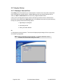
3.0 Reports....................................................................................................... 124
3.1 Generate a Report ............................................................................................. 124
3.2 Creating Custom Reports................................................................................... 125
3.2.1 To save a custom report setting .................................................................................. 125
3.2.2 Selecting a Custom Report setting .............................................................................. 125
3.2.3 To delete a Custom report setting ............................................................................... 126
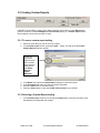
3.3 To Schedule a Report ........................................................................................ 127
3.3.1 Display ......................................................................................................................... 128
3.3.2 Search .......................................................................................................................... 128
3.3.3 To Print the Report: ..................................................................................................... 128
3.3.3.1 Reports- Setup Printer Attributes......................................................................................... 129
3.4 Report Headings ................................................................................................ 130
3.4.1 Report Headings: History............................................................................................. 130
3.4.1.1 History Reports: Display ...................................................................................................... 131
3.4.1.2 History Reports: Search ...................................................................................................... 132
3.4.1.3 History Reports: File Option ................................................................................................ 132
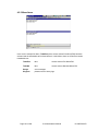
3.4.2 Report Headings: Host ................................................................................................ 133
3.4.2.1 Host Report: Display ........................................................................................................... 133
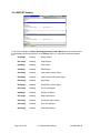
3.4.3 Report Headings: Panel ............................................................................................... 134
3.4.3.1 Panel Report: Display.......................................................................................................... 134
3.4.3.2 Panel Report: Search .......................................................................................................... 134
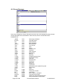
3.4.4 Report Headings: Operator Audit ................................................................................ 135
3.4.4.1 Operator Audit: Display ....................................................................................................... 135
3.4.4.2 Operator Audit: Search........................................................................................................ 136
3.4.4.3 Operator Audit: File Option.................................................................................................. 136
3.4.5 Report Headings: Building Hours ................................................................................ 137
3.4.5.1 Building Hours: Display ....................................................................................................... 137
3.4.5.2 Building Hours: Search........................................................................................................ 138
3.4.5.3 Building Hours: File Option.................................................................................................. 138
3.4.6 Report Headings: Reader ............................................................................................ 139
3.4.6.1 Reader Reports: Display ..................................................................................................... 139
3.4.6.2 Reader Reports: Search ...................................................................................................... 139
3.4.7 Report Headings: Input ................................................................................................ 140
3.4.7.1 Input Reports: Display ......................................................................................................... 140
3.4.7.2 Input Reports: Search ......................................................................................................... 140
3.4.8 Report Headings: Output ............................................................................................. 141
3.4.8.1 Output Reports- Display ...................................................................................................... 141
3.4.8.2 Output Reports: Search ....................................................................................................... 141
3.4.9 Report Headings: Floor Groups ................................................................................... 142
3.4.9.1 Floor Groups Reports: Display ............................................................................................ 142
3.4.9.2 Floor Groups Reports: Search ............................................................................................ 142
3.4.10 Report Headings: Card (Authorization) ..................................................................... 143
3.4.10.1 Card (Authorization) Report: Display ................................................................................. 143
3.4.10.2 Card (Authorization) Report: Search ................................................................................. 144
3.4.10.3 Card (Authorization) Report: Search “Time Segment Search Setup” ................................ 144
3.4.11 Report Headings: Authorization Group ...................................................................... 145
3.4.11.1 Authorization Group Reports: Display ............................................................................... 145
3.4.11.2 Authorization Group Reports: Search................................................................................ 145
3.4.12 Report Headings: Card Personal ............................................................................... 146
3.4.12.1 Card Personal Information Report: Display ....................................................................... 146
3.4.12.2 Card Personal Information Report: Search ....................................................................... 146
3.4.13 Report Headings: Card Status ................................................................................... 147
3.4.13.1 Card Status Reports: Display ............................................................................................ 147
3.4.13.2 Card Status Reports: Search ............................................................................................ 147
3.4.14 Report Headings: Time Period .................................................................................. 148
3.4.14.1 Time Period Reports- Display ........................................................................................... 148
Page iv of 206
5.14 Administrator Manual
38-10055-002-D
3.4.14.2 Time Period Reports: Search and Time Segment Search Setup ....................................... 148
3.4.15 Report Headings: Holiday List ................................................................................... 149
3.4.15.1 Holiday List Reports: Display ............................................................................................. 149
3.4.15.2 Holiday List Reports: Search.............................................................................................. 149
3.4.16 Report Headings: Print Badges ................................................................................. 150
3.4.16 Report Headings: Input Alarm ................................................................................... 151
3.4.16.1 Sense Input Alarm Reports: Display .................................................................................. 151
3.4.16.2 Sense Input Alarm Reports: Search................................................................................... 151
3.4.17 Report Headings: Xaction Alarm ............................................................................... 152
3.4.17.1 Transaction Alarm Reports: Display ................................................................................... 152
3.4.17.2 Transaction Alarm Reports: Search ................................................................................... 152
3.4.18 Report Headings: Print Photos .................................................................................. 153
4.0 Miscellaneous ............................................................................................. 154
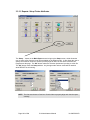
4.1 Understanding Control Counters ........................................................................154
4.1.1 Table of Inputs, Computations, and Outputs ............................................................... 154
4.1.2 Examples ..................................................................................................................... 156
4.1.2.1 EXAMPLE A: Programming an Alarm to Activate an Output Horn ....................................... 156
4.1.2.2 EXAMPLE B: Program Activation of an Output Horn When a Door is Left Open ................. 157
4.1.2.3 EXAMPLE C: Program De-activation of an Output Horn When a Door is Closed ................ 158
4.1.2.4 EXAMPLE D: Program Constant Activation of a Horn Until Door Closes............................ 158
4.1.2.5 EXAMPLE E: Program Automatic Door Open During Working Hours ................................. 159
4.2 EDDAT ...............................................................................................................160
4.2.1 Files ............................................................................................................................. 161
4.2.2 Lists .............................................................................................................................. 162
4.2.3 Menu Items .................................................................................................................. 163
4.2.4 REPORT Heading ....................................................................................................... 164
4.2.5 Screen Messages ........................................................................................................ 165
4.2.6 Dictionary Translator: FindDat .................................................................................... 167
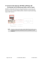
4.3 Communication between LiNC-NET for Windows XP Professional and Vista
Business Edition and the Panels ..............................................................................168
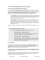
4.3.1 LiNC-NET Initialization of Direct Connect Panels........................................................ 169
4.3.1.1 Access the Site/Host Computer Menu: ................................................................................ 169
4.3.1.2 Port Tab ............................................................................................................................... 169
COM port #3 = IRQ5 COM port #4 = IRQ11 ................................................................................. 169
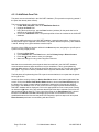
4.3.1.3 Add/Delete Panel Tab .......................................................................................................... 170
4.3.2 Date Format Modification ............................................................................................. 171
4.4 Adding a Client Database ...................................................................................173
4.5 Configuring Windows XP Professional to Display All Files ..................................173
4.7 Adding Facility Code for Client ...........................................................................174
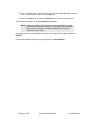
4.8 LiNC-NET Multi-User Systems ...........................................................................176
4.8.1 LiNC-NET XP Professional System ............................................................................. 176
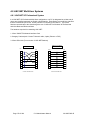
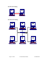
4.8.2 PC to PC Cabling ......................................................................................................... 177
4.8.3 Hub to PC Cabling ....................................................................................................... 177
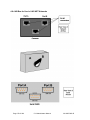
4.8.4 AB Box for Use in LiNC-NET Networks ....................................................................... 178
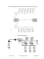
4.8.4.1 LiNC-NET Systems Architecture with Redundant Computers for Fault Tolerance.............. 179
4.8.5 UL 1076 25A Central Supervisory Station Equipment ................................................ 180
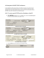
4.8.6 Assignable LiNC-NET TCP/IP Port Numbers .............................................................. 182
4.8.6.1 To create a specific TCP/IP port for a Standalone or Host PC- ........................................... 182
4.8.6.2 To create a specific TCP/IP port for a Host/Workstation PC ................................................ 183
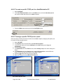
4.8.6.3 To assign a specific TCP/IP port to a panel ......................................................................... 183
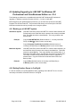
4.9 Updating/Upgrading to LiNC-NET for Windows XP Professional and Vista
Business Edition ver. 5.14 ........................................................................................184
4.9.1 Backing up a LiNC-NET system: ................................................................................. 184
4.9.2 Setting Runtime Parms in ConFigLN ........................................................................... 184
4.9.3 Upgrade Reference Chart - Required Files to be Created from Earlier Versions ....... 187
4.10 Printer Text Setup ............................................................................................188
4.11 UPS Shutdown Software ..................................................................................189
5.0 Configuring your Panel(s) with ConFigUL................................................... 190
Page v of 206
5.14 Administrator Manual
38-10055-002-D
5.1 Connecting to a Panel through a Direct Connection ........................................... 191
DIRECT CONNECT .............................................................................................................. 191
PORT OPEN ......................................................................................................................... 191
5.2 Connecting to a Panel(s) through a LAN Connection ......................................... 194
5.3 Changing a Panel’s Number .............................................................................. 197
5.4 Changing the Panel’s Password ........................................................................ 198
5.5 Changing the Direct Connection/MODEM Configuration .................................... 199
5.6 Changing the Connection Baud Rate - Modem/Direct ........................................ 200
5.7 Add/Change Panel-Modem Telephone Numbers ............................................... 201
5.8 Logging Off from a Panel ................................................................................... 202
5.9 Exiting ConFigUL ............................................................................................... 203
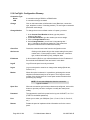
5.10 ConFigUL- Configuration Glossary ............................................................................... 204
Page vi of 206
5.14 Administrator Manual
38-10055-002-D
1.0 Introduction
Welcome to the redesigned LiNC-NET for Windows XP Professional and Vista Business Edition,
the enterprise programming software from PCSC. This user-friendly, PC-based access control
manager is fairly simple to operate and provides Help screens along the way to make operation
even easier. We’ve recently redesigned the LiNC-NET manuals
LiNC-NET for Windows XP Professional and Vista Business Edition operates under the Microsoft
Windows XP Professional and Vista operating systems. The host PC should be dedicated to the
access control system to ensure security integrity and management efficiency. Other Windows
XP Professional and/or Vista applications should not be running concurrently with LiNC-NET for
XP Professional.
LiNC-NET functions on two separate levels: Administrator and User. This manual has been
designed to provide information for the Administrator level of LiNC-NET, which allows an
individual to set the parameters of the system and configure LiNC-NET’s operation with the
different panels it controls. To obtain a complete understanding of LiNC-NET, it should be used in
conjunction with the LiNC-NET for Windows XP Professional and Vista Business Edition Install
Manual and the LiNC-NET for Windows XP Professional and Vista Business Edition User
Manual.
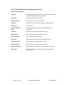
Panel Installation Manuals
MicroLPM
Ultimate
IQ-200
SIM
IQ-400
P/N 33-10019-001
P/N 33-10035-001
P/N 33-10036-001
P/N 33-10037-001
P/N 33-10057-001
Peripheral Installation Manuals
Modem
Stallion
Lantronix
P/N 39-10052-001
P/N 39-10060-001
P/N 39-10056-001
NOTE: The MicroLPM and Ultimate manuals and the peripheral installation
manuals have not been evaluated by UL and are not suitable for UL1076
installations.
NOTE: For clarity in describing the use of LiNC-NET, the MicroLPM, IQ, SIM and
Ultimate PCBs will be referred to as the PANEL.
NOTE:
LiNC-NET for Windows XP Professional and Vista Business Edition
ver. 5.14.07 or greater is Windows Vista compatible.
Page 1 of 206
5.14 Administrator Manual
38-10055-002-D
1.3 Installation and Setup
Along with the Help screens, this guide describes how to setup your system quickly and easily.
Refer to the LiNC-NET for Windows XP Professional and Vista Business Edition Installation
Guide (P/N 33-10055-002) for proper installation of the LiNC-NET system. Refer to the LiNCNET for Windows XP Professional and Vista Business Edition User Guide (P/N 37-10055002) for the day-to-day operation and maintenance of your system. The User Guide provides
information on entering data regarding card assignment, time periods, downloading records to the
Panel(s), and door operations.
NOTE: Some of the screens shown in the LiNC-NET 5.14 Admin Manual make
reference to LiNC-NET 5.14.1. Except for screens where the software now
functions and appears differently in the current version of LiNC-NET 5.14,
please assume that the functionality shown in these older screens is still
correct for this version.
Page 2 of 206
5.14 Administrator Manual
38-10055-002-D
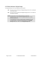
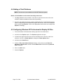
2.0 Using LiNC-NET
RememberIn a Multi-User or Concentrator system, PC’s must be booted up in the following order:
1. Host PC
2. Concentrator PC(s)
3. Workstation PC(s)
Booting up the system in a different order could cause network communication problems.
Also, in a Multi-User or Concentrator system, PCs must be shut down in the following order:
1. Workstation PC(s)
2. Concentrator PC(s)
3. Host PC
Shutting down the system in a different order could cause network communication problems.
Page 3 of 206
5.14 Administrator Manual
38-10055-002-D
2.1 Coming and Going
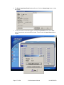
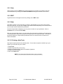
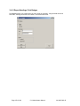
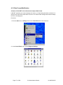
2.1.1 Starting LiNC-NET
1. In Windows, press Start at the bottom of the screen. The menu will display a list of programs.
Click on Programs and then click on LNv5_14_xx.
2. Double-click on the LiNC-NET icon and the password menu will appear.
3. Enter 0 and then the password PYMTF to sign on to LiNC-NET. The System menu will
appear.
NOTE If you have installed a client database, enter the name of the client
before entering a password.
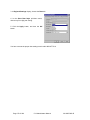
2.1.2 Exiting LiNC-NET
From the System or User Commands Menu, press the EXIT button at the bottom of the screen
to sign off LiNC-NET.
The Sign-on screen will appear. Enter your default Exit name (1) and then the password (EXIT)
to terminate LiNC-NET.
NOTE During system set up, a system password is installed that will allow
varying levels of access to LiNC-NET for Windows XP Professional and
Vista Business Edition. There will be both an access password and an
exiting password.
NOTE To prevent data loss or database corruption while LiNC-NET is running,
you MUST use your Exit password. DO NOT use a warm boot (CTRLALT-DEL) or a cold boot (Power switch off) to terminate the LiNC-NET
application software.
Page 4 of 206
5.14 Administrator Manual
38-10055-002-D
2.2 System Commands and Menus
System Menu
A section of the LiNC-NET program is used by the LiNC-NET System Administrator to establish
the basic system parameters of LiNC-NET. The System Menu also gives access to features such
the Password Menu, which are restricted from the User Menu.
User Menu
A section of the LiNC-NET program that is used by the normal operators of the LiNC-NET
System. The User Menu functions for the day-to-day use of the LiNC-NET system, including
activating and reactivating cards and establishing time periods and holidays. For a detailed
description of the User Menu, please see the LiNC-NET 5.14 for Windows XP Professional User
Guide (P/N 37-10055-002).
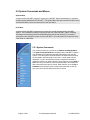
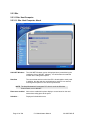
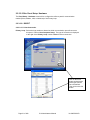
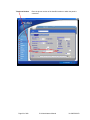
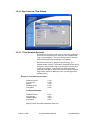
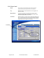
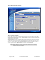
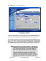
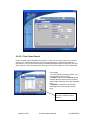
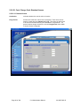
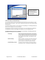
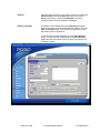
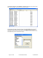
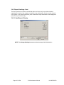
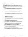
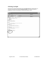
2.2.1 System Commands
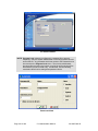
This section provides an overview of the System Commands Menu.
The System Commands Menu is displayed after LiNC-NET is started
from Windows XP Professional and the Administrator logs onto the
system. From the System Commands Menu all features and functions
are accessible. After selecting a menu item, a set of options will be
displayed. You can use either the mouse or keyboard command to
initiate the function you wish to access. Some features, such as Bulk or
Door have only one function screen associated with it and will access
that screen when the button is clicked. Other features, such as Site or
Hardware have several function screens associated with it, and will
give you a list of choices when the button is clicked.
Page 5 of 206
5.14 Administrator Manual
38-10055-002-D
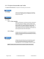
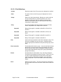
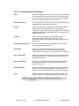
2.2.1.1 The System Commands Menu and Tool Bar
The System Commands Menu is comprised of the following main menu items:
2.2.1.2 Bulk
Used for bulk initialization of data, including Card Technology,
Access Times, Daylight Savings, Card Database Format, and
Entry/Exit enforcement.
2.2.1.3 Site
2.2.1.3.1 Host computer
Allows the administrator to configure the method in which panels
will connect to the Host computer. The Host computer screen
allows an administrator to establish the method that a panel, or
groups of panels, will communicate with the Host computer. The
Host computer screen assigns COM ports, establishes the
method of communication to each COM port (modem, direct, or
LAN), establishes the number of panels that are connected, and
lists the physical location of the Host computer.
2.2.1.3.2 Panel
Configures each panel’s parameters, such as Daylight Savings,
Entry/Exit enforcement, method of communication to the Host
Computer, its assigned Time Period, and its location in reference
to the Host Computer.
2.2.1.4 Door
Configures door parameters such as card technology, access
time, auto-unlock time, and two-person minimum occupancy
rule. Access Actions define what (if any) action should
automatically turn on or off, and program counter time outputs.
NOTE Familiarity with the panel functions is required to implement this function.
Page 6 of 206
5.14 Administrator Manual
38-10055-002-D
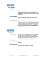
2.2.1.5 Hardware
2.2.1.5.1 Input
Configures sense input number, name to door number, and
assigns the type of alarm, door sense, input counter, etc. An
administrator also can define the counter actions that will
automatically occur when input transitions from state-to-state
(Normal/Closed, Alarm/Ajar, Trouble /Forced), i.e., link the inputs
to the outputs.
2.2.1.5.2 Output
Names and defines outputs and sets their functions. These
parameters determine when to turn outputs on and off, as well as
define the actions when entering and exiting time periods.
2.2.1.5.3 Floor Groups
Controls the destination of an elevator cab based on a card’s
authorization attributes. When a card is swiped at a reader inside
a cab, the time period/floor group pairs assigned to the card are
evaluated to determine which relays the card can activate at the
current time. Of those relays, the ones that are assigned to the
reader engage the floor buttons from which the cardholder can
make a selection.
2.2.1.6 Card
2.2.1.6.1 Add
The Card menu defines the cardholder data. All the options are
here. Each card can be assigned the following information:
cardholder name, normal or long access, override capability with
event lockout and access costs, escort status, entry/exit
exemption, card group specification, affiliation, counter number
class, PIN, authorization group, and expiration dates.
2.2.1.6.2 Change
Allows an administrator to add a range of cards with the same
information.
2.2.1.6.3 LiNC-ID
Refer to the LiNC-ID manual P/N 33-10042-001.
Page 7 of 206
5.14 Administrator Manual
38-10055-002-D
2.2.1.7 Integrity
2.2.1.7.1 Backup
Only History files will be backed up to the selected drive.
2.2.1.8 Password
2.2.1.8.1 Password
Each password is defined with access privileges that determine
which functions are available to an operator. The initial system
password is PYMTF. In addition to passwords and ID levels,
class levels (None, System, User, Exit, and switch) can be
designated based on each operator’s program level.
2.2.1.8.2 Program Levels
In addition to passwords, program levels within the main access
options (System, User, and Switch [System and User] and
Reports) can be designated for each operator.
2.2.1.9 Alarms
LiNC-NET supports 2 types of alarms: 1) Sense Input and 2)
Transaction. Sense input alarms are physical inputs driven by
alarm devices, such as magnetic contacts, glass break, and
passive infrared detectors. Transaction alarms are created by
Host and panel transactions, such as an access denied, a disk
error, a Logon occurrence, etc.
2.2.1.9.1 Alarm Acknowledgment
An alarm record may be defined at the Host by assigning a panel
sense input record to a Host alarm record. When an alarm is
detected at the panel, it can cause the corresponding alarm at
the Host to be set and an alarm event to be logged in the journal
file. An alarm condition at the Host/Workstation causes the alarm
icon at the top of the screen to flash red-white and activates a
break out box to acknowledge the alarms.
2.2.1.10 Logger
LiNC-NET maintains a logger (history) file comprised of records
transferred from various panels. The logger records the following
information: the PC host number (unless the system is a standalone unit), the panel number, the alarm status, the date and
time logged, the date and time of occurrence, the name and
location of where the transaction took place, and a code
reference.
Page 8 of 206
5.14 Administrator Manual
38-10055-002-D
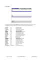
2.2.1.11 Reports
LiNC-NET is capable of producing reports on the screen or
printer. The report setup window contains a tabbed notebook.
The Display page allows the user to select the fields to be
included in the report and the Search page allows the user to
specify the search criteria. The Display page also contains
buttons under Change Heading that allow the user to alter the
heading and the column widths of the fields. Refer to the User
Guide.
2.2.1.12 Help
This screen assists in the data entry process and defines the
criteria required for proper operation.
2.2.1.13 User Commands
2.2.1.13.1 User (Switch)
This allows you to switch from the System Commands menu to
the User menu. The sign on password must have the Switch
class selected.
2.2.1.13.2 Exit
Logoff allows you to sign-off from LiNC-NET for Windows XP
Professional and Vista Business Edition and return to Password
entry.
Page 9 of 206
5.14 Administrator Manual
38-10055-002-D
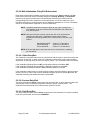
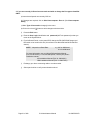
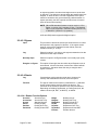
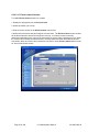
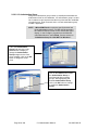
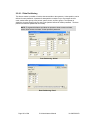
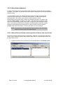
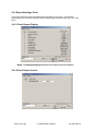
2.2.1.14 Data Entry and Modification
To display or make modifications to the LiNC-NET for Windows XP Professional and Vista
Business Edition database, follow these instructions:
1. Enter a file selection. (Example: Site). Key letters are underlined in each file name.
Press Alt-S to access Site files. The sub-menu listing displays Host and Panel. Tab or
arrow key to your selection. Press Enter. Or click on the selection or the icon with the
mouse button.
2. Click on to the block that you wish to modify using the mouse or use the Tab key from the
keyboard.
3. Position the cursor at the data field that you wish to modify or add to, and highlight the
field by clicking on the block. A range window, described below, will appear on the screen
for those fields that offer multiple options.
4. A data field can be modified in one of the following ways:
• Some fields require that the operator enter the data. (Example: the name field).
Enter the data, then press the mouse button or the Tab key to advance.
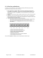
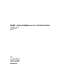
• Other fields will have a navigator bar (shown below), which will appear at the
top of the file.
a.
b.
c.
d.
e.
f.
g.
a. Set the current record to the first record.
b. Set the current record to the previous record.
c. Set the current record to the next record.
d. Set the current record to the last record.
e. Delete the current record.
f. Write changes to the current record to the database.
g. Cancel edits to the current record.
All record fields (System and User) contain the legal keyboard character input.
Page 10 of 206
5.14 Administrator Manual
38-10055-002-D
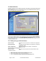
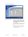
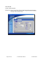
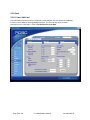
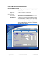
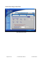
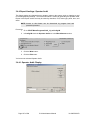
2.2.2 Bulk Initialization
LiNC-NET enables the user to initialize every panel in the system to user-selected default values.
Bulk Initialization defines the card technology: Access Times, Daylight Savings start and stop
dates, Card Table format, and Entry/Exit options.
If you have just installed LiNC-NET using ConFigLN, you will notice that the Bulk Initialization
page is almost exactly the same as the Create Data Base: Default Values page. You will also
notice that the entries made in the Create Data Base: Default Values page will appear here in
the Bulk Initialization page.
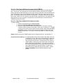
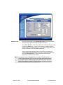
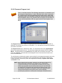
2.2.2.1 Making Changes in Bulk Initialization
Select All Fields
This button selects all data fields. All fields will be displayed in
bold.
Deselect All Fields
This button clears the selection for all data fields. All fields will
be displayed in gray.
Select a Single Entry
Right-click on the field to be changed. The field will be
highlighted in bold.
Start Bulk Change of All Panels
(Selected Fields)
This button starts the update of the selected fields for each
panel.
To initialize all panels:
1. Make all appropriate changes for Bulk Initialization of the panels.
2. Right-click the header to each item to select/deselect.
3. Select the Start Bulk Change of All Panels (Selected Fields) button.
Page 11 of 206
5.14 Administrator Manual
38-10055-002-D
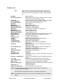
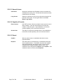
2.2.2.2 Bulk Initialization: Card Technology
In this section, you must select the card reader technology that you will implement into your
access control system. Select the appropriate type of card reader in the Format window.
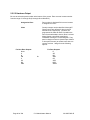
The available card technology formats are as follows:
ProTech
Readers
BR-350, BR-351, BR-352, BR-370, BR-371, All Hughes ID Proximity
MagStripe
BR-450, BR-451, BR-452, BR-470, BR-471
Watermark
Any Watermark card with the 12-digit format
PCSC Wiegand
34-bit PCSC Wiegand format, All Sensor Proximity Readers
Indala
Indala Proximity format
12-Digit
No site code; Magnetic Stripe
Sensor 26
Standard Sensor 26-bit format
NOTE BR-700 readers are setup as Sensor 26 readers.
Sensor 34
Standard Sensor 34-bit format
Special
Special format
PCSC 26, 37, 40
Standard PCSC Proximity format
Corp_1000
Special 35-bit HID Proximity format
Motorola 32
Special 32-bit motorola Proximity format
Smartcard_40
HID 40-bit Smartcard format
A letter or additional reference description that describes the reader type can follow the
card technology:
PIN-Pad
(I)
Page 12 of 206
PIN Pad with the reader.
Insert Reader
5.14 Administrator Manual
38-10055-002-D
2.2.2.3 Bulk Initialization: Door Lock Access Time
The Door Access Time is the length of time that the door lock is to be energized. The actual
length of time is 1/2 second less than the number of seconds specified. For example, access
time value of 1 denotes 1/2 second of access and time value of 5 denotes 4 1/2 seconds. Value
of 1 is generally used for turnstiles.
You must select time values for both the Standard Access and Long Access:
•
Standard Access is the normal door lock energize time. Select an access time from 1-253
seconds (2-253 seconds for elevator readers).
•
Long Access is the door lock energize time for cardholders that require a longer access time
(i.e. an individual with a disability). Select an access time from 2-254 seconds (3-254
seconds for elevator readers).
2.2.2.4 Bulk Initialization: Card Table Format
Primary Expiration
If you select Global, the system automatically selects the Primary expiration date for all types of
readers. You must select Global, if user-select PIN is to be used.
If you select Park-Only (Secondary Expiration), each cardholder has 2 card expiration dates,
with the parking expiration date automatically set to Date. One date controls the access privilege
for “parking” type readers and the other for all other types of readers. This unique function allows
the system administrator to automatically deny access to cardholders at parking readers, yet
allow them to pass through facility related readers.
PIN or Expiration Date (Parking Readers)
If you select Park-Only as the primary expiration choice the system automatically selects Date. If
you select PIN (only available when primary expiration is set to Global), you will have the
capability of user-select 4-digit PIN codes. These PIN codes are used in conjunction with a reader
and PIN Pad.
Names for Cardholders Exist
PCSC panel products have the ability to store the cardholder names within the panel itself.
However, in the MicroLPM selecting this option will decrease the number of cardholders from
1016 to 600 cardholders (the capacity of the IQ/SIM panels are not effected by downloading). If
you require names and more cardholders than 600, you will need to purchase a memory
expansion kit for the MicroLPM.
12-Digit Card Number
Various card formats are available within the system. When using the MagStripe or Watermark
format where a site code is not available, this option must be selected. The panel series supports
8 - 12 digit ABA Track 2 format data
Page 13 of 206
5.14 Administrator Manual
38-10055-002-D
2.2.2.5 Bulk Initialization: Daylight Savings
The Daylight Savings Cycle may be programmed into the panel.
Start
Enter the date of the official start of Daylight Savings (In the U.S. it is usually the
first Sunday of April).
Stop
Enter the date of the official end of Daylight Savings (In the U.S. it is usually the
last Sunday of October).
NOTE If the panel does not roll into Daylight Savings (no Start date
programmed), then it won’t roll out of Daylight Savings (even if a Stop
date was programmed).
For IQ-200 with IQ 7.9.12Q (or newer) firmware or SIM with SI-7.9.15S
(or newer) firmware. The panel will automatically roll out of Daylight
Savings Time even if it didn’t roll into Daylight Savings Time.
Page 14 of 206
5.14 Administrator Manual
38-10055-002-D
2.2.2.6 Bulk Initialization: Entry/Exit Enforcement
Each panel supports three separate entry/exit enforcement levels: Strict, Lenient, and Soft.
Each enforcement level can be individually assigned to Parking, Building, or Department
readers, but is enforced (under normal circumstances) when the Entry function and the
corresponding Exit function readers are on the same panel. In order to broaden the use of
Entry/Exit enforcement, an administrator can use Regional Antipassback. For more information,
see the 5.14 Install Manual- Appendix A (P/N: 33-10055-002).
NOTE
Entry/Exit enforcement cannot be done (at any of the 3 levels) if the
entry readers are on one panel and the corresponding exit readers are
on a different panel.
NOTE These panel firmware versions require the door to be opened before
changing the card status. Repeated accesses will be granted
(regardless of the anti-passback level of enforcement) if the door is not
opened:
Standard MicroLPMPlus 2 MicroLPMPlus 4 MicroLPM-
Version 1.9.5 and above
Version 3.9.5 and above
Version 7.9.13 and above
NOTE All IQ and SIM panels require that the door be opened prior to updating
the card status.
2.2.2.6.1 Strict Entry/Exit
The cardholder’s entry/exit status must be synchronized with the system, otherwise an entry/exit
error will be announced. In other words, the cardholder must have the proper status (building,
department, or parking) before he uses an entry/exit reader. The card status must be as follows:
If the cardholder’s Building Status is IN then Department Status can be IN or OUT.
If the cardholder’s Building Status is OUT, the Department Status must be OUT.
If the cardholder’s Department Status is IN then Building Status must be IN.
If the cardholder’s status does not comply with the reader’s entry/exit definition, then the system
will deny access. In other words, when a cardholder attempts to enter a building IN reader, the
cardholder’s building and department status must be OUT.
2.2.2.6.2 Lenient Entry/Exit
This level is the same as Strict except on the first use of the card, in which case the system will
automatically reset the building and department status to proper synchronization. The
cardholder’s second attempt at the reader will then grant him access.
2.2.2.6.3 Soft Entry/Exit
This level follows the same rules as Strict except that an error transaction is recorded, all status
levels are synchronized, and access is GRANTED.
Page 15 of 206
5.14 Administrator Manual
38-10055-002-D
2.2.3 Site
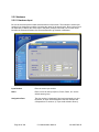
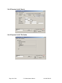
2.2.3.1 Site: Host Computer
2.2.3.1.1 Site: Host Computer: About
LiNC-NET Windows
The LiNC-NET Windows version is displayed here (entered during the
installation of the LiNC-NET software). You will be asked to state this
number when calling with inquiries.
Date/time
The current date and time at the Host PC is downloaded to each panel.
In addition, the date and time are broadcast to each PC in a network,
ensuring that all panels on-line will be synchronized.
NOTE The Host/Workstation/Concentrator PC’s time is set in the Windows
Control Panel, not in LiNC-NET.
Photo trace enabled
Able to have cardholder’s photo display to a user based on the card
transactions taking place at the panel.
Schedule…
Displays all scheduled events.
Page 16 of 206
5.14 Administrator Manual
38-10055-002-D
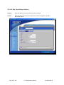
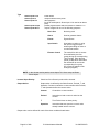
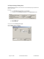
2.2.3.1.2 Site: Host Computer: Loop
Loop to COM Port Assignment
Select the serial communication port number (COM 1,
COM 2, COM 3, or COM 4) for one of 4 possible panel
loops when you are NOT using a Stallion® port. If you
are using a Stallion® port, then LiNC-NET is capable of
13 communication ports (COM 1 – COM 13). If no loop
exists, select NotInUse.
Each communication port used for direct connect, LAN,
or modem must be assigned to a loop before it can be
used.
A COM port MUST be used for any LAN connection.
A Log Off MUST take place to initialize the COM port
after any changes take place.
Page 17 of 206
5.14 Administrator Manual
38-10055-002-D
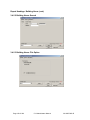
2.2.3.1.2 Site: Host Computer: Loop (cont.)
Modem Dial Out
A single AutoDial modem (e.g., U.S. Robotics Sportster
28.8/33.6/56k Fax-Modem) may be used at the PC for
dial out to any of the panels in the LiNC-NET system.
Consult factory for other compatible modems.
Select the port where the modem for auto-dial is
connected. This COM port number must be different
than the direct connect COM port number. If no autodial modem is being used, select NotInUse.
The COM port selected for this field must have the type
of connection field set to modem.
For further information, refer to Modem Restoration after
Power Loss Technical Bulletin 39-10052-001.
Page 18 of 206
5.14 Administrator Manual
38-10055-002-D
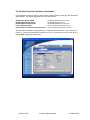
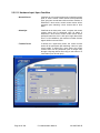
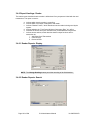
2.2.3.1.3 Site: Host Computer: Port
Port Configuration
Defines the communication/connection type.
Type of Connection
Direct (Direct Connect RS232/RS485 type)
Modem (Autodial up connection)
LAN (Local Area Network through an Ethernet (NIC) Network Interface
card)
NotInUse (if the com port is not utilized by the LiNC-NET)
Baud Rate
1200, 2400, 4800, 9600, 14k, 19k, 38k, 56k, 57k, 115k, 128k, 256k
Telephone Number
Phone # of modem installed at LiNC-NET Host PC
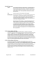
MODEM initialization AT (Attention) commands used to train an external MODEM connected
to a COM Port.
NOTE:
Page 19 of 206
User may initialize or modify the modem string command to
specify a particular modem for each port. Currently, the system
is defaulted to US Robotics Sportster Internal Modem. To
change to an External US Robotics Sportster Modem @33.6 or
higher Baud type in “ATH&F1”.
5.14 Administrator Manual
38-10055-002-D
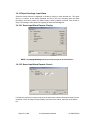
2.2.3.1.3.1 Changing Baud Rate or Port Type:
1. If you are currently in Direct Connect mode and wish to change the Baud rate ONLY:
a) Insure that all panels are currently On Line.
b) If changes are required, click on Sites: Host Computer: Port tab. (See Host
Computer Setup). Make change(s) in menu.
c) Click on the check [] button to write changes to the hard disk.
d) Press the EXIT button to access the Sign On password screen (do NOT exit from
LiNC-NET for Windows XP Professional and Vista Business Edition).
e) Enter the User Login identification and password (NOT exit password) so you will
return to the System Menu. The connection will be re-established automatically and
the new Baud rate will be set.
NOTE If Baud rate was altered and the panel was not on-line, either
alter it back to original setting or modify the panel’s DIP switch
configuration (for more information, see your panel’s Installation
Manual).
2. If you are currently in MODEM (auto dial) mode and wish to change the Baud rate ONLY:
Important!
Baud rate changes should be made in a separate
session. Do NOT combine this change with other
downloading, which may cause the panel to restart.
a) If changes are required, click on Site: Host Computer: Port tab. (See Host
Computer Setup).
b) Make Baud Rate change(s) in menu.
c) Click on the check [] button to write changes to the hard drive.
d) Repeat the following for all panels in the system:
• Dial the panel and hang up by requesting Offline. (At this time, the user
can still dial the panel or the panel can dial the Host and communicate
at the original Baud rate).
• Continue this procedure until all the panels are dialed.
e) Press the EXIT button to access the sign-on screen (do NOT exit from LiNC-NET for
Windows 2000/XP Professional).
f)
Enter the User Login identification and password (NOT exit password) so that you
return to the System Menu.
This will restart (warm boot) all affected panels.
Page 20 of 206
5.14 Administrator Manual
38-10055-002-D
3. If you are currently in Direct Connect mode and wish to change the Port type to AutoDial
ONLY:
a) Insure that all panels are currently Off-Line.
b) If changes are required, click on Site: Host computer: Port tab. (See Host computer
Setup).
c) Make Type of Connection change(s) in the menu.
d) Click on the check [] button to write changes to the hard drive.
f)
Press the Exit button.
g) Enter the User Login identification and password (NOT exit password) so that you
return to the System Menu.
h) For all affected Panels, on the panel PCB, change the RS-232/RS-485 jumper and
DIP switch to let location 04 =8.X (this relates to the MicroLPM and MicroLPM Plus
boards).
NOTE X depends on Baud Rate:
e.g. 8.8 for 9600 baud
8.2 for 2400 baud
For more information, see your MicroLPM Installation Manual(P/N: 33-10019-001). For IQ and SIM panels, consult your panel’s
installation manual:
-IQ Installations Manual (P/N: 33-10036-001)
-SIM Installations Manual (P/N: 33-10037-001)
i)
Exchange your direct connecting cable to a modem cable.
j)
Select panel online to verify communication method.
Page 21 of 206
5.14 Administrator Manual
38-10055-002-D
4. If you are currently in MODEM (auto dial) mode and wish to change the Port type to
Direct Connect ONLY:
Important!!
Baud rate changes should be made in a separate session. Do
NOT combine this change with other downloading, which may
cause the panel to restart.
a) Insure that the panel is currently offline.
b) If changes are required, click on Site: Host Computer: Port tab. (See Host Computer
Setup).
c) Make Type of Connection change(s) in menu.
d) Press the Exit button.
e) Enter the User Login identification and password (NOT exit password) so that you
return to the System Menu.
f)
For all affected Panel’s, on the panel PCB, change the RS-232/RS-485 jumper and DIP
switch to let location 04 =8.X (this relates to the MicroLPM and MicroLPM Plus boards).
g) Exchange your direct connecting cable to a MODEM cable.
NOTE X depends on Baud Rate:
e.g. 8.8 for 9600 baud
8.2 for 2400 baud
For more information, see your MicroLPM Installation ManualP/N 33-10019-001. For IQ and SIM panels, consult your
panel’s installation manual:
-IQ Installations Manual (P/N: 33-10036-001)
-SIM Installations Manual (P/N: 33-10037-001)
h) Select panel online to verify communication method.
Page 22 of 206
5.14 Administrator Manual
38-10055-002-D
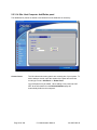
5. If you are currently in LAN mode and wish to change the IP address type ONLY:
a) Insure that the panel is currently offline.
b) If you wish to change the IP address, click on the Site: Panel: Hardware tab.
c) Under LAN connection, highlight the current address in the IP Address block
d) Enter the new address.
e) Consult with your LAN administrator or MIS personnel to ensure the correct address
(when using a LAN connection, make sure that the terminal server is connected to the
panel).
f)
Click on the check [] button at the top left side of the menu to save the new address.
g) Press the Exit button to log off the System menu.
h) Enter the User Login identification and password (NOT exit password) so that you
return to the System Menu.
Page 23 of 206
5.14 Administrator Manual
38-10055-002-D
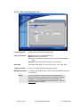
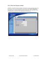
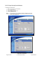
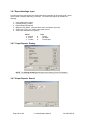
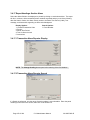
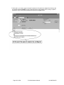
2.2.3.1.4 Site: Host Computer: Add/Delete panel
The databases for panels are added to and deleted from the database as necessary.
Current Count
This file indicates how many panels are currently part of your system. To
add or delete a module, enter the number of the panel and select the
model type. Press + Add Panel or - Delete Panel.
Up to 200 panels may be added. When adding a new panel into LiNCNET all the information from the Bulk Initialization page will
automatically default to the new panel.
Page 24 of 206
5.14 Administrator Manual
38-10055-002-D
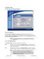
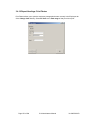
2.2.3.1.5 Site: Host Computer: Address
LiNC-NET 5.14 now has a feature that allows an Administrator to give the physical location of the
Host computer and its connected Workstations. By choosing either the Host or Workstation
radio buttons, you can enter the address to different connected PC’s. It is only possible to enter
one Host address, but LiNC-NET allows addressing for 20 Workstations.
Page 25 of 206
5.14 Administrator Manual
38-10055-002-D
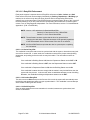
2.2.3.2 Site: Panel
2.2.3.2.1 Site: Panel Setup: Features
2.2.3.2.1.1 Password
The default password PYMTF is used to logon the panel during the initial set-up. It is
recommended that once communication is established with the panel (on-line), the password
should be changed. Since PYMTF is used for initial set-up, you must use PYMTF to logon each
time a new panel is added to the system.
NOTE The panel password will return to factory default when the panel is
factory reset.
2.2.3.2.1.2 Daylight Savings
The Daylight Savings cycle may be programmed into the panel.
Enter
Enter the date of the official start of Daylight Savings. In the US it the first
Sunday in April. Enter the date that daylight savings begins in month, day, year
format (e.g., 04/01/2001).
Exit
Enter the date of the official end of Daylight Savings. In the US it is the last
Sunday in October. Enter the ending date in the same format (e.g. 10/04/2001).
NOTE Do to Y2K compliancy, the PC must be configured for a 4-digit
year format. Consult the Windows Control Panel/Regional
Settings and select the Short Date format of mm/dd/yyyy and the
Long Date format of mm/dd/yyyy to accommodate the LiNC-NET
for uninterrupted (proper) operation.
Page 26 of 206
5.14 Administrator Manual
38-10055-002-D
2.2.3.2.1.3 Entry/Exit Enforcement
Each panel supports 3 separate levels of Entry/Exit enforcement: Strict, Lenient, and Soft.
Each enforcement level can be assigned individually by Parking, Department, or Building type
readers, but is enforced only when the Entry function and its corresponding Exit function
reader(s) are on the same panel. Entry/Exit Enforcement cannot function (at any of the 3 levels) if
the Entry reader(s) are on one panel and the corresponding Exit readers are on another panel
unless a user is using Regional Antipassback. For more information, see the 5.14 Install ManualAppendix A (P/N 33-10055-002).
NOTE Version 1.9.5 and above for Standard MicroLPMs
Version 3.9.5 and above for Plus 2 MicroLPMs
Version 7.9.13 for Plus 4 MicroLPMs
NOTE These firmware versions require that the door be opened before
changing the card status. Repeated accesses will be granted (regardless
of the anti-passback level of enforcement) if the door is not opened.
NOTE All IQ and SIM Panels require that the door be opened prior to updating
the card status.
2.2.3.2.1.3.1 Strict Entry/Exit
The cardholder’s entry/exit status must be synchronized with the system, otherwise an entry/exit
error will be announced. In other words, the cardholder must have the proper status (building,
department, and parking) before he uses an entry/exit reader. The card status must be as
follows:
If the cardholder’s Building Status is IN, then the Department Status can be OUT or IN.
If the cardholder’s Building Status is OUT, then the Department Status must be OUT.
If the cardholder’s Department Status is IN, then the Building Status must be IN.
If the cardholder’s status does not comply with the reader’s entry/exit definition, then the
system will deny access. In other words, when a cardholder attempts to enter a building
IN reader, the cardholder building and department status must be OUT.
2.2.3.2.1.3.2 Lenient Entry/Exit
This is the same as Strict except on the first use of the card; the system will automatically reset
the building and department status to proper synchronization. The cardholder’s second attempt
at the reader will then grant him access.
2.2.3.2.1.3.3 Soft Entry/Exit
Same as strict except that an error transaction is recorded, statuses are synchronized, and
access is GRANTED.
Page 27 of 206
5.14 Administrator Manual
38-10055-002-D
2.2.3.2.1.3.4 In Case of LockIn/LockOut
To restore operation to a card whose owner has been locked in or out due to an entry/exit (antipassback) violation, simply deactivate and then re-activate the card from the Change Card screen
with the panel(s) online.
NOTE
Depending on the Panel firmware version, when toggling
status for In/Out of doors, either an Authorized card or
an Authorized card followed by a door open activation
will toggle In/Out status.
NOTE
MicroLPM Firmware versions 1.9.5 and 7.9.13 or higher
provide for an Authorized card followed by a Door Open
to toggle In/Out status.
NOTE
MicroLPM versions 1.9.5, 3.9.5, 5.9.16, or 7.9.13 or
lower provides for an Authorized card ONLY to toggle
In/Out status.
NOTE
All IQ and SIM panels require that the door be opened
prior to updating the card status.
Page 28 of 206
5.14 Administrator Manual
38-10055-002-D
2.2.3.2.1.4 Card Table Format
Primary Expiration (Park/Global)
Panels support parking, department, and
building type readers. The system can
automatically expire a card for Parking Only
readers if the PARK-ONLY is selected. Click on
the options:
Park-Only
Selects a secondary card expiration date to be
used at parking-type readers.
Global
Selects a primary card expiration date to be
used at all readers.
PIN or Expiration Date (Parking Readers)
Because there is limited cardholder space in
RAM in the panel, the Global expiration date
automatically selects the PIN option.
Conversely, selection of the Park-only option
selects the date option.
Names for Cardholders Exist
The cardholder file within the standard panel can
be configured with or without names. If the
panel is configured with names, it requires more
memory space and lowers the card capacity.
However, all “Plus” series MicroLPMs default to
cards with names. For IQ and SIM panels,
downloading names has no bearing on card
capacity
Select “” if names for cardholders exist in the
panel. If this section is changed, System
Parameters and Cards files must be
downloaded to the panel in order for the
changes to take effect.
12-Digit Card Numbers
When using MagStripe or Watermark formats
where a site code is NOT available; this option
must be selected. The IQ/SIM/Micro-series
supports 5 to 12-digit ABA track 2 format data.
Select this option if the cards being used are 12digit cards or do NOT select if cards are binary.
If this section is changed, System Parameters
and Cards files must be downloaded to the
panel in order for the changes to take effect.
Various card formats are available within the
system.
Page 29 of 206
5.14 Administrator Manual
38-10055-002-D
Renewable Shunt
The Renewable Shunt renews the access time if
a second card swipe occurs before the previous
completed transaction. It is recommended that
the access time be set equal to, or longer, than
the shunt time to avoid problems.
Multiple facility codes
A panel can be made aware if LiNC-NET system
uses multiple facility codes within one system
(ie. one building with multiple tenants).
NOTE: Only the IQ, Ultimate and SIM panels can recognize Multiple facility codes within
a system.
Duress Event
A control counter can be activated when a
duress code is entered by the cardholder. Once
a sense input has been selected, an output must
be assigned for an alarm.
The duress code is the Normal PIN code, except
that the first and second digits are incremented
by one. If the first or second Regular PIN digit is
9, the duress code digit is calculated as a 0.
Select a Control Counter that will enable an
output for duress (1-40). Refer to Access
Action.
NOTE Duress can only be initiated
from a cardreader WITH PIN
pad, NOT from a PIN pad only
terminal.
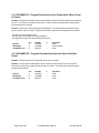
Example of Duress PIN code Assignment:
Regular
DURESS
3129
4229
1999
2099
Do NOT assign user-defined PIN codes 0000,
0911 and 9811, as they are reserved by the
system.
NOTE User-defined pin codes are
programmed in the Card Add or
Card Change screens.
Page 30 of 206
5.14 Administrator Manual
38-10055-002-D
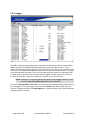
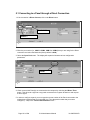
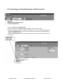
2.2.3.2.2 Site: Panel Setup: Hardware
The Panel Setup : Hardware screen will be configured to reflect a panel’s communication
method (Direct, Modem, LAN, or NotInUse) of its Primary Loop.
2.2.3.2.2.1 DIRECT
2.2.3.2.2.1.1 Host Connection
Primary Loop: Select the loop number to determine which communication port will connect to
this panel. Refer to Host Computer Setup. The type of connection is displayed
to the right of the Primary Loop number: Direct for direct connection.
Click on the Scroll
button and select the
panel type from the
list to be defined.
Then click on the OK
button
Page 31 of 206
5.14 Administrator Manual
38-10055-002-D
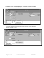
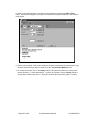
2.2.3.2.2.2 MODEM
2.2.3.2.2.2.1 Host Connection:
Primary Loop: Select the loop number to configure to which communication port this panel will
connect. Refer to Host Computer Setup. The type of connection is displayed to
the right of the Primary Loop number: Modem for modem connection.
2.2.3.2.2.2.2 MODEM CONTROL (if primary loop is modem)
2.2.3.2.2.2.3 Secondary Loop
Select the loop number for the secondary connection. This is necessary if the
panel attempts to notify the HOST PC of an alarm or a backlog of events by
dialing in at the same time as another panel. Although only one panel would be
able to connect to the dial-out modem (see HOST Computer Setup), it can dial
into and receive calls from panels. To alleviate contention, additional modems
may be connected to the Host PC for receiving incoming calls (up to 3 as long as
a COM port isn’t already assigned for Direct or LAN connected panel(s)).
NOTE Only the modem designated dial-out in the HOST
computer’s set-up screen can initiate a call from the PC
to a control panel. The additional modem(s) are for
receiving calls only.
Each modem connected to the HOST PC has its own dedicated telephone line, and therefore its
own telephone number. When the secondary loop is specified to be a loop number assigned to
one of the modems that only receives calls, the panel will first attempt contacting the host via the
primary loop. If the primary loop is busy, than the secondary loop will attempt a dial-up
connection to the HOST.
A maximum of two loops may be assigned to any panel for dialing into the HOST. Also, the PC
can accommodate up to a total of four internal modems (only one can dial out from the PC).
Therefore, different secondary loop numbers can be assigned to different panels to minimize
contention.
History Transfer
When a panel is connected to LiNC-NET over a dial-up modem, history
transactions are transmitted to LiNC-NET under the following conditions:
1. Upon an alarm
2. At the start of the Time Period
3. At a pre-defined number of transactions
Time Period
Select the Time Period when the panel will call the Host to upload its
transaction buffer. The panel will call automatically at the start of each
segment within the time period selected.
Backlog Threshold
Defined as the number of transactions that will be recorded in the panel
before it automatically calls the HOST to transfer the information. For a
standard panel setup, we recommend a backlog threshold of 300 to
insure that more recent transactions do not overwrite older ones.
NOTE Failing to transfer messages will create gaps in subsequent History reports.
Page 32 of 206
5.14 Administrator Manual
38-10055-002-D
Telephone Number
Page 33 of 206
Enter the phone number of the AutoDial modem to which the panel is
connected.
5.14 Administrator Manual
38-10055-002-D
2.2.3.2.2.3 LAN
2.2.3.2.2.3.1 Host Connection
Primary Loop Select the loop number to determine which communication port will connect to
this panel. Refer to Host Computer Setup. The type of connection is displayed
to the right of the loop selection: LAN.
Page 34 of 206
5.14 Administrator Manual
38-10055-002-D
2.2.3.2.2.3.2 LAN Connection
IP Address
Enter the IP address for the selected Panel Terminal Server. Consult with your
LAN administrator or MIS personnel.
IP Port
Port Address
For ULT/IQ/SIM, enter 3001
For Black Box Terminal Server, enter 3001.
For LANtronix Terminal Server, enter 3001
LAN Connection
For ULT/IQ/SIM, enter 3001
For Black Box Terminal Server, enter 3001.
For LANtronix Terminal Server, enter 3001
When using a LAN connection, make sure that the Terminal Server is connected to the panel or
to a panel through a hub. The Terminal Server end may require a DB25 male end connector or
mounting to screw terminals.
For further information regarding the LANtronix Terminal Server, refer to Technical Bulletin 3910056-001.
NOTE: The Ultimate Panel and the LANtronix MSS1-T RS-232 Serial
Terminal Server have not been evaluated by UL, and are not
suitable for UL installations.
Bulk Download
This is a feature for the Ultimate only. It gives a user the ability to
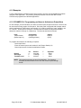
download large packets to the Ultimate’s memory.
Tamper Detect
Enter the sense input number 13 for tamper detect.
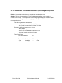
Printer Baud Rate
Define the speed of the serial printer that is connected to the panel:
-MicroLPM -1200, 2400, 4800, 9600
-IQ/SIM – 9600 only
NOTE: For further information regarding individual panels, refer to the
following Installation Guides:
MicroLPM
P/N 33-10019-001
Ultimate
P/N 33-10035-001
IQ-200
P/N 33-10036-001
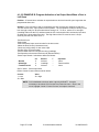
SIM
P/N 33-10037-001
IQ-400
P/N 33-10057-001
Page 35 of 206
5.14 Administrator Manual
38-10055-002-D
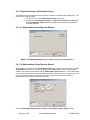
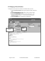
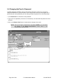
2.2.3.2.3 Site: Panel Setup: Address
Address
Enter the address of the site where the panel is located.
Contact
Enter the Name and number of the Person to contact in regards to the LiNCNET/Panel system.
Page 36 of 206
5.14 Administrator Manual
38-10055-002-D
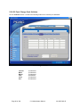
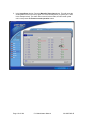
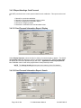
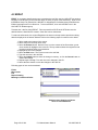
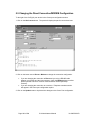
2.2.3.2.4 Site: Panel Setup: Panel Time Periods
Each panel is given the ability to handle 31 different time periods that are defined through the
User menu. If a particular panel uses time periods separate from other panels in the system, they
can be created and monitored here. LiNC-NET has the ability to support 99,999 unique Time
Periods.
Page 37 of 206
5.14 Administrator Manual
38-10055-002-D
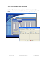
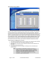
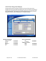
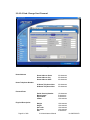
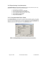
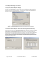
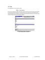
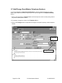
2.2.3.2.4.1 Setting Half Day Holiday Time Periods
This feature for LiNC-NET 5.14 allows an administrator to set a multiple Holiday Time Periods
that can be used in the LiNC-NET User menu. Though this process affects LiNC-NET Users in
their holiday time period decision-making skills more than Administrators, setting the holiday time
period can only be done by accessing the LiNC-NET System menu.
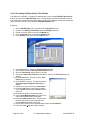
Procedure:
1.
2.
3.
4.
5.
In the LiNC-NET User menu, proceed to the Time Period screen.
Create a new Holiday Time Period within the Holiday tab-screen.
Create a name for the time period in the Name box.
Press the Switch button to access the System menu.
In the System menu, proceed to the Panel screen.
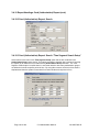
6.
7.
8.
9.
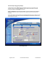
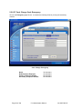
In the Panel screen, choose the Panel Time Periods tab.
Choose a panel that the Holiday Time Period will effect.
Select a Time Period, and press the […] button.
Choose the Panel Time Period that you wish to create in the Time Period pop-up
window.
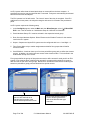
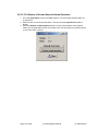
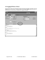
Press the OK button. This will close the Time
Period pop-up window.
Press the Edit List button. This will bring up the
Panel Time period mapped names pop-up
window.
Create a new name for this new Time Period.
Press the Add button to add it to the existing
list of mapped names, and the Delete button to
remove it.
Press the OK button to close the window.
In the List of Mapped Names pull-down menu,
choose the name that was just created.
Press the Add to Panel button. This will make
the time period active on the panel the next
time the Host downloads to the panel.
Repeat this process for every panel that will require this Time Period.
Press the check [√] button to save changes.
10.
11.
12.
13.
14.
15.
16.
17.
18.
Page 38 of 206
5.14 Administrator Manual
38-10055-002-D
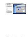
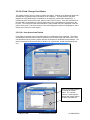
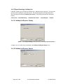
19. Press the Switch button to access the User menu and proceed to the Holiday List
screen.
20. To select the default
Holiday Time Period for
this date, press the date
square once. This will make
the calendar date square
turn blue.
21. To use the alternate
Holiday time period, select
the name from the Master
List.
22. Pull the text from the Master
List Column into the
Mapped name column. This
will now make the alternate
Holiday time period active
for that particular day on all
participating panels.
Page 39 of 206
5.14 Administrator Manual
38-10055-002-D
2.2.4 Door
2.2.4.0 Door Overview
For the following door configuration data entry, enter the door number to be configured and
assign a name to the door (example: Executive). Don’t forget to select the panel that is being
used in the door configuration. At the bottom of the screen, position the mouse cursor on the tab
for the appropriate panel and click on the index tab.
Also enter the reader selection data. Each panel supports up to 2 readers per door. If the first
terminal letter for a door will be changed from the default, enter the letter from the range (a
through l). If a second reader terminal for a door will be changed from the default, it will always
be different from the one programmed as the first reader. Enter the letter from the range (a
through l). If you are not utilizing entry and exit readers, bypass this section. If the doorway has
an entry and an exit reader, you must define the reader number for the second reader. This will
allow standard lock output and door sense control via software control, NOT hardware control.
The selection will take away from the total number of terminals used for doors.
NOTE Before a reader can be assigned as a second reader, it must be
dissociated from its current door assignment as a first reader.
For example, to assign reader b on door 1, it must first be
dissociated from door 2.
Page 40 of 206
5.14 Administrator Manual
38-10055-002-D
2.2.4.1 Door Overview: Time Related
2.2.4.1.1 Time Duration (Seconds)
Access time is the amount of time that a door lock is energized.
There are two access timers for each door lock: Standard and
Long (for handicapped). The choice of which timer to be used
will be determined by the cardholder’s Long attribute.
Enter the access time by using the command keys. The
standard length of time is 5 seconds for Standard access and 10
seconds for Long access. Enter 1 for the quickest access time
or 255 for the longest. Long access time follows the same
parameters, and will be used in the event more time is required.
Long Access values are always at least 1 second longer than
standard values.
Ranges for Time Values (in seconds):
Standard Access:
Long Access:
Egress:
Standard Shunt:
Long Shunt:
1-253
2-254
1-253
2-254
3-255
For Elevator Readers:
Standard Access:
Long Access:
Standard Shunt:
Long Shunt:
2-253
3-254
3-254
4-255
Egress (unlock) time utilizes Standard Shunt time.
Page 41 of 206
5.14 Administrator Manual
38-10055-002-D
NOTE Attempts to program Time duration less than 2 seconds in an
elevator-type reader will cause floor relays to NOT be engaged
upon card authorization even though the green LED will
momentarily light on the reader.
Egress
(Request to Exit) time has a range of 1-253 seconds.
Enter the time length desired.
Standard Shunt
The length of time to disable the door status alarm
during normal egress is the standard shunt time. The
default time is 8 seconds. Enter a different amount of
time if necessary. Shunt time is always at least 1
second longer than the corresponding access time.
Long Shunt
The length of time to disable the door status when a
cardholder with the Long Access feature presents a card
is the long shunt time. The default time is 12 seconds.
Enter a different amount of time if necessary.
2.2.4.1.2 Time Period Control
When using a reader and keypad combination, the PIN
pad and/or door may be disabled during user-selected
times. Assign a time period (2 - 31) to disable the
requirement for PIN entry. The user will only be required
to use the card reader and bypass entering his PIN code
during this time period.
Time Period for PIN_Pad Disable
The PIN Pad may be automatically disabled during these
periods by defining the Time Period to disable the use of
the PIN Pad (0-999). The user will only be required to
use the cardreader during this time period. To select the
Time Period for PIN Pad disable, enter the Time Period
number desired.
Time Period for Auto Unlock
Scheduled automatic door unlock can be programmed
by defining the time period (0-999) during which the door
is to be unlocked. If this option is selected, the door
remains unlocked until the designated time period
expires. Users will NOT be required to use their cards or
PIN codes during this time period. If this option is not
selected, the door remains locked until authorized card
or egress transaction occurs.
Page 42 of 206
5.14 Administrator Manual
38-10055-002-D
2.2.4.2 Door Overview: Hardware connections
Door assignment criteria consists of sense inputs, control counters, reader type, and transaction
specifications. The default assignments are set up as follows:
Default Door Sense Inputs
Reader Detect Sense Inputs
Default Egress Sense Inputs
Lock Control Counters
Door Shunt/ Local Alarm Control Counters
are ODD numbers from 17 to 39
are numerical from 1 to 12
are EVEN numbers from 16 to 38
are in numerical order from 1 to 12
are in numerical order from 13 to 24
The first reader terminals are assigned by the 12 alphabet characters a, b, c, etc., through l on
Panel-12. If a second reader will be assigned to a door, it will be taken from one of the other 11
readers NOT assigned to another door.
Page 43 of 206
5.14 Administrator Manual
38-10055-002-D
2.2.4.2.1 Door Lock
Output
This connection specifies the output number (1-12) where the electric
lock for this door is connected. (Refer to your specific Installation
Guide for output location and number.) If a door lock control counter
number will be changed from the default, enter the number from the
range available (1-12). This output will be connected to the electric
lock at the door.
Log
Select this option if lock transactions will be logged.
Normally Open
When this field is selected ([]), the quiescent state of the door relay
is de-energized. This will cause continuity to exist between the
common and normally closed contacts. When an access operation or
an egress (with energize) operation occurs, the door relay will
momentarily energize to temporarily complete continuity between the
common and normally open contacts.
When this field is NOT selected ([ ]), the quiescent state of the door
relay is energized. This will cause continuity to exist between the
common and the normally open contacts. When an access operation
or an egress (with energize) operation occurs, the door relay will
momentarily de-energize to temporarily complete continuity between
the common and the normally closed contacts. Whether the door
operates as a fail-safe or fail-secure environment depends upon the
type of door hardware used (magnetic lock or door strike) and how the
door is programmed.
2.2.4.2.1.1 Door Strikes- Fail Safe
For door strikes, power is required to unlock the door. Therefore, in a fail-safe
environment, wire the door strike hardware across the common and normally closed relay
contacts. Do NOT select ([ ]) the normally open field. When the door relay is in its
quiescent state, the door will be locked. But upon card transaction or egress (with
energize) operation, the relay will de-energize and the door will become momentarily
unlocked. In the event of a power outage to the panel, this will permit the door relay to
de-energize and for continuity to exist between the common and normally closed contact.
Power from the battery-backed power supply will now be applied to the strike causing it to
unlock, until either the battery discharges or panel power is restored.
2.2.4.2.1.2 Door Strikes- Fail Secure
In a fail secure environment, wire the door strike hardware across common and
normally open contacts. Then, select ([]) the normally open field. When the door relay
is in its quiescent state, the door will be locked. But upon card transaction or egress (with
energize) operation, the relay will energize and the door will become momentarily
unlocked. In the event of a power outage to the panel, this will permit the door relay to
de-energize and for continuity to exist between the common and normally closed
contacts. Power from the battery-backed supply will now be removed from the strike
causing it to lock.
Page 44 of 206
5.14 Administrator Manual
38-10055-002-D
2.2.4.2.1.3 Magnetic Locks- Fail Safe
For magnetic locks, power is removed to unlock the door. Therefore, in a fail-safe
environment, wire the magnetic lock across the common and normally open contacts. Do
NOT select
([ ]) the normally open field. When the door relay is in its quiescent state, the door will be
locked. But upon card transaction or egress (with energize) operation, the relay will deenergize and the door will become momentarily unlocked. In the event of a power outage
to the panel, this will permit the door relay to de-energize and for continuity to exist
between the common and normally closed contacts. Power from the battery-backed
power supply will now be removed from the magnetic lock, causing it to unlock until panel
power is restored.
2.2.4.2.1.4 Magnetic Locks- Fail Secure
In a fail-secure environment, wire the magnetic lock across common and normally closed
contacts. Then, select ([]) the normally open field. When the door relay is in its
quiescent state, the door will be locked. But upon card transaction or egress (with
energize) operation, the relay will energize and the door will become momentarily
unlocked. In the event of a power outage to the panel, this will permit the door relay to
de-energize and for continuity to exist between the common and normally closed
contacts. Power from the battery-backed supply will now be applied to the magnetic lock
causing it to secure until the battery discharges.
Summary of the Four Possible Fail-Safe/Fail-Secure Cases:
When using door strikes-For fail-safe operation, wire to COM and N.C. contacts and do NOT select ([ ]), the normally
open field.
-For fail-secure operation, wire to COM and N.O. contacts and select ([]), the normally open
field.
When using magnetic locks-For fail-safe operation, wire to COM and N.O. contacts and do NOT select ([ ]), the normally
open field.
-For fail-secure operation, wire to COM and N.C. contacts and select ([]), the normally open
field.
Page 45 of 206
5.14 Administrator Manual
38-10055-002-D
2.2.4.2.2 Door Sense
Input
This connection describes the sense-input number for the door
sense (door status/door position) contact. Refer to your specific
Panel Installation Guide for sense Input location. If the door
sense input contact for the door will be changed from the default,
enter the number from the range available (0, 16-55, or 56-71 in
an ALM or OUT configuration).
Range Designations
16-23
24-31
32-39
40-47
48-55
MicroLPM
MicroLPM8
MicroLPM12
SAM1 (supervised door sense)
SAM2 (supervised door sense)
16-19
16-23
16-27
16-35
IQ 200
IQ-400
IQ 600
IQ 1000
16-23
16-31
SIM 4
SIM 8
Normally Closed
Click on if the door lock sense input contact is Normally Closed.
A Normally Closed sense input will lock the door when the
system detects an open circuit except when using the Maglock
option.
Mag Lock
When selected, this option will terminate the door lock control
counter activation upon door closure. Otherwise, the system will
terminate the door lock control counter activation upon a door
opening. This option is related to card reader transactions, as
well as egress operations for the specific door. The purpose of
this option is to permit the door to be fully opened while
preserving the magnetic locks deactivated state. Without this
option, at the moment when the door switch contacts changed
their state (indicating that the door was “slightly” opened), the
power to the magnetic lock would be restored. This condition
could cause the lock to immediately pull in and, prematurely,
secure the door prior to the person passing through the access
point.
Page 46 of 206
Meanwhile, the transaction would be recorded as though the
person actually did pass through the door. The shunting of the
door switch contacts (shunt time) is terminated differently
depending upon whether the magnetic lock option is selected.
When the Maglock option is selected, upon a card transaction or
an egress operation, the shunt time begins when the access time
expires. In other words, when the door is unlocked and then
opened, as the door switch contacts are immediately shunted
prior to unlocking, the door remains unlocked until either it is
closed or until its access (unlock) time expires. Should the door
still be open when the access time expires, then the shunt time
will begin at this point in time. However, if the door is closed
prior to the access (unlock) time expiring, the door shunt time is
immediately canceled. Hence, the overall duration of the door
being shunted is the access time plus the shunt time. When the
Maglock option is NOT selected, then upon a card transaction or
5.14 Administrator Manual
38-10055-002-D
an egress operation, the shunt time begins as soon as the door
is unlocked. The shunt time cancels when the specified time has
elapsed, or when the door is closed. Regardless of the option
selection, should the door be accessed (by card transaction or
egress operation), but NOT opened, the shunt time will cancel
upon the access time expiring.
NOTE [MicroLPM standard firmware must be version 1.9.5 or
higher; or version 3.9.5 or higher, if Plus. The Maglock
option is not supported in Plus MicroLPMs (version 2.X)
or MicroELV (version 5.8.X) systems.]
All IQ and SIM panels support the Maglock option.
2.2.4.2.3 Egress
Input
This connection selects the sense input number that is to control
the Request to exit (egress) for this door. If the egress sense
input for a door will be changed from the default, enter the
available number (0, 16-39)**
Log
Select this option if you wish to write egress transactions into the
hard disk for later report creation.
Normally Open
Select this option if the Egress switch is a normally open (N.O.)
contact.
Energize on Egress
This option will energize the door strike when Request to exit is
encountered. All other functions, such as Door Closed will still
be monitored. Activation allows the relay to energize when
egress is allowed.
2.2.4.2.4 Reader
Log
If transactions at this particular reader are to be stored in
memory and transmitted to the host, select this option.
Function
The type of reader and its function is defined here. A standard
access control reader would be defined as Access. The
remainder of the selections pertains to the entry/exit features.
Depending on Building, Department, or Parking entry/exit, the
reader’s function (IN, OUT, or IN/OUT), is defined.
2.2.4.2.4.1 Reader Function Options
AccessIn
AccessOut
Access
ParkIn
ParkOut
ParkInOut
Page 47 of 206
Access IN only
Access OUT only
Standard Access
Parking IN Only
Parking OUT Only
Parking IN and OUT
BldgIn
BldgOut
BldgInOut
DeptIn
DeptOut
DeptInOut
Elevator
5.14 Administrator Manual
Building IN only
Building OUT only
Building IN and OUT
Department IN only
Department OUT only
Department IN and OUT
Elevator Access
38-10055-002-D
Reader (cont.)
Type
Type refers to the card data format that will be accepted by the
reader. Only one format per reader is available. Select the card
data format that will be accepted by the reader from the following
list:
PIN_PAD
ProTech (Hughes ID)
ProTech (I)
ProTech/PIN_PAD
ProTech/PIN_PAD (I)
MagStripe
MagStripe (I)
Magstripe/PIN_PAD
Magstripe/PIN_PAD (I)
Watermark
Watermark (I)
Watermark/PIN_PAD
Watermark/PIN_PAD (I)
PCSC Wiegand
Wiegand/PIN_PAD
Indala
Indala/PIN_PAD
12-Digit
12-Digit (I)
12-Digit/PIN_PAD
12-Digit/PIN_PAD (I)
Sensor-26
Sensor-26/PIN_PAD
Sensor-34
Sensor-34/PIN_PAD
Special
Special/PIN_PAD
PCSC-26, 37, 40
PCSC-26, 37, 40/PIN_PAD
Corp-1000
Corp-1000/PIN_PAD
Motorola-32
Motorola-32/PIN_PAD
Smartcard_40
Smartcard_40/PIN_PAD
BP250 or BP270
BR350, BR370, VR670 (40-bit), PCSC Protech, All Hughes
ID Proximity readers (except 26-bit cards)
PCSC ProTech Insert readers: BR371, BR351, and BR352
ProTech readers with PIN_Pad (swipe readers)
ProTech Insert readers with PIN_Pad
BR450, BR470
BR451, BR452, BR471
BR450/BP250, BR470/BR270
BR450/BP250, BR450/BP250
Any Watermark card with the 12-digit format
Custom Watermark card
Custom Watermark card
Custom Watermark card
34-bit PCSC Wiegand format. All Sensor Proximity readers
34-bit PCSC Wiegand format with BP270 PIN_PAD
All Indala readers (32-bit)
All Indala readers w/PIN Pad
NO Site code; Magnetic stripe, BR450, BR470
BR451, BR452, BR470, BR471
BR470/BR270, BR450/BP250
BR451/BP270, BR471/BP270, BR452/BP250,
BR472,/BP270
Standard Sensor 26-bit format, VR670 26-bit, HID 26-bit,
BR700 BARCODE
BR200/BP270, BR202,/BP270, PRK234, PR235/BP270,
PR232/BP270, PR234/BP270
Standard Sensor 34-bit format, BR200, BR202
BR-200/BP270, BR202/BP270
Proprietary
Proprietary
37-bit format (PCSC), Sensor 26, PCSC 40-bit Protech (HID
Prox Reader)
PCSC 37-bit Prox/BP270, Protech 40-bit/BR270 (HID Prox
Reader)
Fortune 500 format, PR732, PR733, PR735, PR736
Fortune 500 format w/PIN Pad, HID Prox Reader/BP270
Corporate Secure format, Motorola Prox Readers
Corporate Secure format w/PIN Pad, Motorola Prox Readers
w/ Bulletin PIN_PAD
HID 40-bit Smartcard
HID 40-bit Smartcard with PIN_PAD
NOTE A letter or additional reference description that describes the reader type
can follow the card technology:
PIN-PAD indicates a PIN Pad with reader. (I) indicates Insert Reader
NOTE Not all reader/card interfaces are current. Check card data sheet for compatibility
options
Page 48 of 206
5.14 Administrator Manual
38-10055-002-D
2.2.4.2.5 Alarm Control
Output
This connection controls which output number the feature
selected should operate (external shunt or local alarm).
Log
Select this option if output transactions are to be logged in the
LiNC-NET journal.
External Shunt
This feature activates the associated open collector output
during the door-open state. This option can be used to “shunt”
other alarm systems attached to the door.
Local Alarm
Select this option if you wish to have an alarm annunciated at the
door, to inform the user that an alarm message will be generated
and sent to the host if the door is not closed. The open collector
output defined by door output will be activated.
Local Alarm
Page 49 of 206
5.14 Administrator Manual
38-10055-002-D
Alarm Control (cont.)
Duration (seconds)
of local alarm
Amount of time the alarm will sound once it is activated
Shunt Time Period
Defines what time period you do not want the local alarm to
function.
Buzzer Off Upon
ShuntTimer Expiration Select this option if you wish to shut off the buzzer when the
shunt timer expires. Not selecting this field causes the local
alarm output to remain active until the door is closed.
NOTE
MicroLPM firmware level must be version 1.9.1 or higher. MicroLPM
Plus firmware level must be version 2.6L or higher. MicroLPM Plus2
firmware level must be version 3.9.2 or higher). When selected, the
Local Alarm options appear. Enter the duration of the alarm in
seconds and the shunt time period of the alarm. The duration field
specifies (in seconds) at what interval before the door shunt expires
the local alarm output will be initiated.
All IQ and SIM panels support the local alarm feature.
Page 50 of 206
5.14 Administrator Manual
38-10055-002-D
2.2.4.3 Door Overview: Features
2.2.4.3.1 Access Lockout
Panels support features that automatically deny access upon an event condition or when TwoPerson Minimum Occupancy is in effect. Event Lockout is a feature that automatically denies
access upon an event condition.
If Event Lockout is in effect, a cardholder that normally would be able to gain access is denied.
A reader can be set into Event Lockout automatically through a card access, sense input, or by
time of day. These conditions adjust the Event Lockout counter value and when the value is
equal to or greater than the High Threshold, the reader is in Event Lockout.
NOTE Event Lockout only affects readers. Egress operations are not defeated
during an event lockout condition.
Page 51 of 206
5.14 Administrator Manual
38-10055-002-D
2.2.4.3.1.1 Event Lockout Counter
To enable Event Lockout counter for a reader:
1. Display the appropriate door in Door Overview.
2. Select the reader (1st or 2nd).
3. Enter a counter number in the Event Lockout counter field.
4. Define the event action that will modify the counter value. The Event Lockout counter number
will be the threshold for denied access (Event Lockout). It will deny access to normally
authorized cardholders in the event of an alarm within an area or when a parking lot is full. When
the counter value reaches the selected value, normally authorized cards will be denied access.
Conversely, when the counter value reaches its low value or lower, Event Lockout will be turned
off, and normal access returns.
Page 52 of 206
5.14 Administrator Manual
38-10055-002-D
2.2.4.3.1.2 Two-Person Minimum Occupancy Rule (TPMOR)
The panel can restrict access to a secured area by monitoring the number of people within that
area. If no one is in the monitored area, the two-person minimum occupancy rule (TPMOR)
feature requires two valid cardholders in order to gain access to that area. Once the area has the
required two people, other valid cardholders will gain access without the need to enter or exit in
pairs. The last two people are also required to exit together. This feature requires an IN and an
OUT reader. When no one is in the area, and the first card is presented, the card reader LED will
flash red/green for up to 6 seconds. During this time, the second card must be presented for
TPMOR processing to be lifted.
2.2.4.3.1.3 Two-Person Minimum Occupancy Counter:
To enable TPMOR:
1. Display the appropriate door in Door Overview.
2. Select the Two-Person Minimum Occupancy box.
3. Enter the control counter number in the counter field. This option is used to
count the number of people or cars within a room, area, or parking lot. If TPMOR
is selected, the control counter number must be entered. When using the Room
Occupancy counter, be sure to have at least one reader counting entries and
another counting exits. This control counter should NOT be used for any other
functions.
Output Outputs used by the TPMOR system must be configured with Low = Ø and High = 2.
Access Cost for Card Group The MicroLPM Plus series offers a feature that debits units from
a cardholder’s record. Debit can be determined by a reader and
by a card group. Enter the number of units (0-999) to debit for
each card group at this reader. Depending upon the number of
credits issued to a card group; the Access cost for a card group
will be subtracted from that balance. The system will subtract
the value that was assigned for the card group as access cost for
every valid transaction at a specified reader or readers (only
designated readers) debits the card (account) status. See the
Change Card/Status screen to allocate credits to a card
account.
Page 53 of 206
5.14 Administrator Manual
38-10055-002-D
2.2.4.3.2 Phototrace
This feature can be used only if the administrator’s system came
equipped with PCSC’s LiNC-ID video-badging software.
Activating Phototrace allows the User to see each cardholder’s
archived badge-photo. The pull-down menu allows three options:
2.2.4.3.2.1 Trace Types
None
no extra features
TraceOnly
only Phototrace
SolicitOpen
Solicit Open
feature
To learn more about Phototrace and it’s uses, please consult the Linc-ID Administrator
manual.
NOTE Depending on the panel firmware version, when toggling status for In/Out
of doors, either an Authorized card or an Authorized card followed by a
door open activation, will toggle In/Out status.
NOTE MicroLPM Firmware versions 1.9.5 and 7.9.5 or higher provide for an
Authorized card followed by a Door Open to toggle In/Out status.
NOTE MicroLPM Firmware versions 1.9.5, 3.9.5, 5.9.16, or 7.9.5 or lower
provides for an Authorized card ONLY to toggle In/Out status.
NOTE All IQ and SIM panels require the door to be opened prior to updating the
card status.
Page 54 of 206
5.14 Administrator Manual
38-10055-002-D
2.2.4.4 Door Overview: Access Actions
Door Overview: Access actions
(MicroLPM Plus, IQ, SIM)
LiNC-NET provides output control via a card access or denial. The file tabs at the bottom of this
screen will be different, depending on whether a standard or a MicroLPM-Plus controls your
system. The screen above displays the MicroLPM-Plus panel. The number of outputs (control
counters) that may be operated by a card transaction is dependent upon the panel type.
The Card Group programming influences the action performed when the card transaction takes
place. For each possible card group, control may be determined by whether the card transaction
occurs during an active or inactive time period schedule. The output operation is determined by
the card being authorized (access granted) or unauthorized (access denied) when presented to a
specific reader. When using a Standard MicroLPM, the card group (A, B, or AB) will determine
the output that is affected. This provides a unique output operation to be generated at the same
reader, dependent on the Group of the card presented.
NOTE Standard Panel cards of Group AB may influence two outputs since the
operations under the Group A and the Group B file tabs are implemented
for an authorized card of this group. The file tabs at the bottom will
display: ‘Every Access, Card Group A, Card Group B, and Denied
Access. When using a MicroLPM-Plus, the card Group (A, B, AB) or the
Escorted (Escort Required) group will determine the output that is
affected. This again provides for a unique output operation to be
generated at the same reader, dependent on the group of the card
presented. When an authorized card transaction occurs at a specific
reader, the operations programmed under the first action, second action,
third action may enable 3 outputs. Refer to the bottom file tabs in the
panel above.
Page 55 of 206
5.14 Administrator Manual
38-10055-002-D
Reader Selection
Select the reader (a-l) that you wish to program. Enter a name to be
associated with the panel and the reader or simply give it a Door number
(example: Door#4).
2.2.4.4.0 Access Action Summary Based On Standard and Plus-type Panels
2.2.4.4.0.1 Standard Panel
Every Access-
1 additional output operation (plus door lock/ external shunt
output activation). Regardless of Card Group.
Card Group A*-
1 additional output operation (plus the above defined Every
Access operation) for cards who are defined as Card Group A.
Card Group B*-
1 additional output operation (plus the above defined Every
Access operation) for cards who are defined as Card Group B.
Denied Access-
1 single output operation (no door lock/ external shunt output
activation) regardless of the card’s Group assignment.
* For Card Group AB cards
The Card Group A, Card Group B, and Every Access
operations are activated upon the card being authorized.
NOTE When a card is not a Card Group AB card (Card Group= None, Card
Group A, or Card Group B) then up to two additional output operations
(plus door lock/ external shunt output activation) may be attained when
the card is granted access. When a card is a Card Group AB card, then
up to three additional output operations (plus door lock/ external shunt
output activation) may be attained when the card is granted access.
Page 56 of 206
5.14 Administrator Manual
38-10055-002-D
2.2.4.4.0.2 MicroLPM Plus/IQ/SIM
Access Granted 1st Access- 1 additional output operation (if Card Group assigned to the card
matches the Card Group assigned to this option) plus door lock/
external shunt output activation.
Access Granted 2nd Access- 1 additional output operation (if Card Group assigned to the card
matches the Card Group assigned to this option) plus door lock/
external shunt output activation.
Access Granted 3rd Access- 1 additional output operation (if Card Group assigned to the card
matches the Card Group assigned to this option) plus door lock/
external shunt output activation.
Access Denied Action-
1 additional output operation (if the Card Group assigned to the
card matches the Card Group assignment to this option) but
without door lock/ external shunt output activation.
NOTE When an authorized card’s Group matches the Card Group assigned to
either the 1st, 2nd or 3rd Access granted actions then for each match, a
separate output activation will occur. In addition, the door lock/ external
shunt output activation will occur. Because the Card Group assigned (to
the Access Granted actions) may be either All, A, B, Escorted (defined
below)-
Page 57 of 206
5.14 Administrator Manual
38-10055-002-D
2.2.4.4.1 Access Action Commands
Card Group
(Access Granted 1st, 2nd, 3rd, denied) Card Group Options
All
Card Group A, B, AB, and None as defined in the Card Add/Change
screens
A
Card Group A as defined in the Card Add/Change screens.
B
Card Group B as defined in the Card Add/Change screens.
Escorted
An Escorted Card is card of any class (A, B, AB, and None) but is defined as
Escort Required in the Card Add/Change screens.
Access Action (at the Reader)
For normal access and Alternate access actions, control counter action is composed of the When
Time Period (Active or Not Active) priority option, Preload, T and Operation. Select from the
following options:
Every Access or
Access Granted First action
Counter
Select the first option Card Group access privileges from the options
given. Enter All if access will be granted fully at the reader, A for oneway entry, B for one-way exit.
Enter the control counter number for the first option. Select from 040, A, B, C, D, or H (H class control counter is only available in the
Plus series).
2.2.4.4.1.1 Time Period Control
Time Period
Preload
Enter a time period (2-31) for the access action. Program the action
that will take place when the time period is Active and when the time
period is Not Active.
Select the Preload action from the following options:
NoLoad
No preload action (CC value is not changed)
LoadZero
Load CC with zero
LoadLow
Load CC with low threshold value
LoadHigh
Load CC with high threshold value
LoadMax
Load CC with maximum value
AddPreset
Add preset value to CC
FlipOutput
Load CC with zero or high threshold to flip output
T
The system allows the user to override any other CC action and give
priority to the time period’s control operations. To do so, you must
define whether or not time period has priority. If non-zero value is
assigned to the auto-unlock output, the T flag will automatically be
selected for the segment start.
Page 58 of 206
5.14 Administrator Manual
38-10055-002-D
2.2.4.4.1.2 Time Period Control
Operation
Select the operation to be performed on the control counter from
the following list:
None
No Operation
Decrement
Decrement CC
DecrementSec
Start auto-decrement on second
DecrementMin
Start auto-decrement on minute
Clear
Clear auto increment decrement
Increment
Increment CC
IncrementSec
Start auto-increment on second
IncrementMin
Start auto-increment on minute
OverrideTp
Override time period control
TpSuspend
Suspend time period control (until (one ON cycle) restore)
TpResume
Resume time period control
For 2nd action (Card Group A access), activate another Control Counter or a class of Control
Counters with a valid access for a cardholder whose card is defined as Card Group A or Card
Group AB at this reader:
1. Enter the control counter number (1-40) or group (A, B, C, or D).
2. Follow the previous steps for Preload, Time Period, and Operation.
3. For third action (Card Group B access), for cards defined as Group B or AB, follow the
preceding instructions to initiate.
Access Denied (Action)
Page 59 of 206
A control counter action can be executed when a
cardholder is denied access. The first group of entries
(Time Period, Preload, T, Operation) defines the control
counter action during an active Time Period card denial.
The second set of entries describes what to do during
the Access Denied Not active Time Period. If the Time
Period control operations will override the Control
Counter action, select “T” Field entry. Enter the control
counter number (1-40) or control counter class (A, B, C,
D) to initiate. Follow the identical procedure for the
access granted counters above.
5.14 Administrator Manual
38-10055-002-D
2.2.5 Hardware
2.2.5.1 Hardware-Input
Be sure to select the panel number tab at the bottom of the screen. Then select the sense-input
number to be displayed or modified, (including the name for the sense input). Enter a name (up to
20 characters) to identify the sense input to the panel (example: Door1si4). Click on the check
box after the selection and then click the arrow buttons to go forward or backward.
Input Number
Enter the sense input number
Name
Enter a name for the input (Door1, Door2, Door3, etc. are the
default names given).
Assigned to Door
The door number is displayed if this input is assigned to a door.
By default, an input will be assigned to the Door number that
corresponds to it’s number (ie. Input 4 will default to Door 4).
Page 60 of 206
5.14 Administrator Manual
38-10055-002-D
Type
Sense Inputs 1-12
Sense Input 13
Sense Inputs 14
reader detect
Tamper Detects for the panel
other purposes
(In the IQ series panel, Sense Input 14 is used as an alarm
point).
(default) Egress Sense and Door Sense for readers 1-12
may be assigned for one of the following purposes:
Sense Inputs 16-39
Sense Inputs 40-71
Not in Use
Not being used
Alarm
Used to generate alarms
Events
Egress Sense
Input Switch
Used when counting or using
the input to trigger outputs
without generating an alarm or
real time transaction.
Elevator Control
The card will be able to access
floors defined by the floor
groups during the corresponding
Time Periods. Enter the time
period (0-999) which will enable
the cardholder to access the
corresponding floor group.
(ELV must be enabled in the
ConfigLN program).
NOTE In the elevator series panels, sense inputs 72-119 are setup as Button
Sense Inputs.
Inverted Input Polarity
Check box if the Sense Input should be inverted.
Output Action
Output action is defined by the fields Counter, Preload, T, and
Operation. Counter controls the counter number while Preload,
T, and Operation define the counter action.
Counter
Controls the counter number.
Preload
Instruction to load a numeric value into the
counter.
T
Time Period does not have priority.
Operation
Instruction that acts upon the numeric value
already loaded into the counter.
Output action can be defined for each of the three conditions listed below.
Page 61 of 206
5.14 Administrator Manual
38-10055-002-D
2.2.5.1.1 Hardware Input: Upon Condition
...Normal/Closed
If defined as a dry contact alarm point, supervisory alarm
point, or event. Control counter action will be performed
upon going into normal status after an alarm condition. If
defined as a door sense, control counter action will be
executed upon detecting a door closure after a door
alarm.
...Alarm/Ajar
If defined as an alarm point, event, or egress, the control
counter action will be performed upon an alarm. If
defined as a door sense, control counter action will be
performed when the door is left open longer than shunt
time. For UL Installations, the maximum number of alarm
signals shall not exceed 1000.
...Trouble/Forced
If defined as a supervisory alarm, the control counter
action will be performed upon detecting a short or open
circuit trouble. If defined as a door sense, the control
counter action will be performed upon an illegal entry
through a doorway without first using an exit button or a
card reader (Door forced open).
Input Screen with Calibration
Page 62 of 206
5.14 Administrator Manual
38-10055-002-D
NOTE
IQ, SIM, and ULTIMATE panels with 7.9.16 or higher only
support the supervised point by point digital calibration. The
Ultimate panel has not been evaluated by UL and is not suitable
for UL1076 Installations.
NOTE
Each individual sense input MUST be in normal state with
180/300 resistors and proper setup of inverted polarity, before
calibration takes place.
NOTE
Notification that calibration took place is at LED of Panel will be
OFF with corresponding Sense Input #.
Page 63 of 206
5.14 Administrator Manual
38-10055-002-D
2.2.5.1.2 Proper Point by Point Calibration
To calibrate an individual door1.
2.
3.
4.
Make sure door/input in normal position.
Click on Supervised box
Save changes on navigation bar
Click the Calibrate button
Note:
The door/input will not calibrate correctly if changes are not first
saved in the navigation bar.
Input Without Calibration
Input Screen - Supervised
Page 64 of 206
5.14 Administrator Manual
38-10055-002-D
Preload
NoLoad
LoadZero
LoadLow
LoadHigh
LoadMax
AddPreset
FlipOutput
No preload action (CC value is not changed)
Load CC with zero
Load CC with low threshold value
Load CC with high threshold value
Load CC with maximum value
Add preset value to CC.
Load CC with low or high threshold to flip output
T
The system allows the user to override any other CC action and
give priority to the Time Period’s control operations. Define
whether or not time period has priority. Enter a [] if the Time
Period does not have priority. If a non-zero value is assigned to
the auto-unlock time period of a door lock output, T flag will
automatically be selected for the segment start.
Operation
Select the operation to be performed on the control counter from
the following list of instructions which act upon the numeric
values already loaded into the counter:
None
Decrement
DecrementSec
DecrementMin
Clear
Increment
IncrementSec
IncrementMin
OverrideTp
TpSuspend
TpResume
No Operation
Decrement CC
Start auto-decrement on second
Start auto-decrement on minute
Clear auto increment decrement
Increment CC
Start auto-increment on second
Start auto-increment on minute
Override time period control (one ON cycle)
Suspend time period control (until restore)
Resume time period control
Shunt by Time Period,
Shunting an alarm condition may be done by time period or
bycontrol counter number or class. Under Time Period, enter
the time period (1-31) which will shunt the alarm. At counter,
enter the active control counter which will shunt the alarm (1-40,
or counter class A, B, C, or D).
Shunt by Counter
Enter the control counter number, which will activate or
deactivate sense inputs upon an alarm condition. For Preloads,
Time Period priority, and Operations, select from the following
option instructions which load numeric values into the counter.
Page 65 of 206
5.14 Administrator Manual
38-10055-002-D
2.2.5.2 Hardware-Output
Be sure to select the panel number at the bottom of the screen. Enter a control counter number
from the range of 1 through 40 (41 through 88 on MicroELV).
Assigned to Door
Door number is displayed if this control counter
is assigned to a door.
Class
Control counters can be classified A through E.
Class D and E are defined for door lock and
external shunt, respectively. Counters are
programmed as Class D and E from within the
Door Overview hardware screen, Door Lock and
Alarm Control output fields respectively.
CLASSES A through C is user-assigned. They
permit a single occurrence (sense-input violation
or time period control) to actuate more than one
counter at a time. Assign from the following
options:
For Non-Door Outputs
None
A
B
AB
C
AC
BC
ABC
Page 66 of 206
Or
For Door Outputs
D
AD
BD
ABD
CD
ACD
BCD
ABCD
5.14 Administrator Manual
38-10055-002-D
Output with Counter Static Values
2.2.5.2.1 Time Period Control
Control counters can be affected by Time Period. Action can occur upon entry into, as well as
exit from, the Time Period. Enter the Time Period by which door outputs will be activated or
deactivated. The Time Period will cause the following prescribed actions to transpire: one upon
entry (when the Time Period goes into effect) and one upon Exit (when the Time Period ends).
For example,
1.The time period 2 is entered, which may
be the time from 8:00 to 17:00.
2. LoadHi is entered under Preload, which
indicates that the control counter is loaded
with the high value upon entry (the beginning
time).
3. LoadZero is entered for exit Preload,
indicating a zero value load (the ending
time).
Output with Pop-Up Screens
Page 67 of 206
Click on the Search button
to scroll to a different panel
number.
5.14 Administrator Manual
38-10055-002-D
The door functions (opening, in this case) are automatically overridden upon Time Period end
with the entry of Clear (Clr) under the Operations block. For Preloads, Time Periods, and
Operation, select from the following options:
Preload
NoLoad
LoadZero
LoadLow
LoadHigh
LoadMax
AddPreset
FlipOutput
T
No preload action (CC value is not changed)
Load CC with zero
Load CC with low threshold value
Load CC with high threshold value
Load CC with maximum value
Add preset value to CC
Load CC with low or high threshold to toggle output
The system allows the user to override any other CC action and
give priority to the time periods control operations. Define
whether or not time period has priority. Enter a [] if the Time
Period does not have priority. If a non-zero value is assigned to
the auto-unlock time period of a door lock output, a T flag will
automatically be selected for the segment start.
Operation
Select the operation to be performed on the control counter from the
following list:
None
Decrement
DecrementSec
DecrementMin
Clear
Increment
IncrementSec
IncrementMin
OverrideTp
TpSuspend
TpResume
Page 68 of 206
No Operation
Decrement CC
Start auto-decrement on second
Start auto-decrement on minute
Clear auto increment decrement
Increment CC
Start auto-increment on second
Start auto-increment on minute
Override time period control (one ON cycle)
Suspend time period control (until restore)
Resume time period control
5.14 Administrator Manual
38-10055-002-D
Class
Control counters can be classified A through E. Class D and E
are defined within the Door Overview Hardware screen for door
lock and external shunt, respectively. CLASSES A through C
are user-assigned. They permit a single occurrence (senseinput violation or card transaction) to activate more than one
counter at a time. Assign from the following options:
For Non-Door Outputs
None
A
AD
AB
C
AC
BC
ABC
Or
For Door Outputs
D
AD
BD
ABD
CD
ACD
BCD
ABCD
Inverted
[de-energize upon activation] Place [] to de-energize upon activation.
Log It
If the transaction will be logged into the LiNC-NET journal, click
on the box [].
Time Period Control
Control counters can be affected by Time Period. Action can
occur upon entry into, as well as exit from, the Time Period.
Enter the Time Period by which outputs will be activated or
deactivated.
The Time Period will cause the following prescribed actions: one
upon Entry (when the Time Period goes into effect) and one
upon Exit (when the Time Period ends).
Example:
1. Time period 2 is entered, which may be the time from 08:00 to17:00.
2. LoadHi is entered under Preload, which would indicate that the control
counter is loaded with the high value upon entry (the beginning time).
3. LoadZero is entered for exit Preload, indicating a zero value load (the
ending time). The door functions (opening, in this case) are
automatically overridden upon Time Period end with the entry of
Clear (Clr) under the Operations block.
For Preloads, Time Periods, and Operation, select from the following options:
Preload
NoLoad
LoadZero
LoadLow
LoadHigh
LoadMax
AddPreset
FlipOutput
Page 69 of 206
No preload action (CC value is not changed)
Load CC with zero
Load CC with low threshold value
Load CC with high threshold value
Load CC with maximum value
Load CC with low or high threshold to toggle output
5.14 Administrator Manual
38-10055-002-D
T
The system allows the user to override any other CC
action and give priority to the time periods control
operations. Define whether or not time period has
priority. Enter an X if the Time Period does not have
priority.
Operation
Select the operation to be performed on the control
counter from the following list:
None
Decrement
DecrementSec
DecrementMin
Clear
Increment
IncrementSec
IncrementMin
OverrideTp
TpSuspend
TpResume
Counter Static Values
No Operation
Decrement CC
Start auto-decrement on second
Start auto-decrement on minute
Clear auto increment decrement
Increment CC
Start auto-increment on second
Start auto-increment on minute
Override time period control (one ON cycle)
Suspend time period control (until restore)
Resume time period control
After each operation, the counter value is compared to
the Counter Static Values (Low and High). The Low
value is used to turn the defined output OFF and the
High value is used to turn the output ON.
When a counter value is being incremented and equals
the High value, the defined output will be activated.
When the counter value decrements, and the counter
value equals the Low value, the output will be
deactivated.
Low
High
Max
Preset
Low Threshold. Deactivate the output when the counter
reaches this value.
High Threshold. Activate the output when the counter
reaches this value.
Maximum value. Counter will not exceed this value.
Max must be greater than or equal to the High value.
Preset value. A user-defined value that can be loaded
into the counter.
NOTE When using Elevator Control, the Low counter value should be 0 and the
High counter value should be 2. Do NOT modify these values in an
elevator panel.
Page 70 of 206
5.14 Administrator Manual
38-10055-002-D
2.2.5.3 Floor Groups (ELV)
Elevator control is defined as restricting access to specific floors in a building. The typical floor
select panel interfaces to the elevator panel through a common ground system. Each pushbutton has a wire connected to the panel that carries the signal alerting the panel which floor was
selected. The purpose of the ELV is to interrupt the signal from the push-button and the panel.
When an authorized cardholder uses the system, the ELV allows the signal from the push-button
to be received by the panel. The ELV restricts access by limiting a cardholder’s choice of floors
in the elevator cab. The ELV is placed between the floor selection panel (push-button) in the
elevator cab and the elevator panel. The ELV allows the elevator panel to receive only those
floor selections from the floor selection panel which the cardholder is authorized to access.
Typical operation of an ELV system is as follows:
1. The cardholder swipes/presents a card to the system via a cardreader (and/or PIN Pad).
2. The system determines which floors that the cardholder can access.
3. If the cardholder is authorized, the ELV allows the signals from the push-button to be
processed.
4. The cardholder then selects the floor.
5. The elevator panel receives the message, controlling the cab to the desired (and
authorized) floor.
NOTE The cardholder is responsible for selecting only one floor. In
addition, the panel can only monitor which floors a cardholder
may select. It is not able to determine what floor was selected.
Single floor latching with destination reporting is under
development. This will prohibit multiple floors from being
selected by a single card presentation.
Page 71 of 206
5.14 Administrator Manual
38-10055-002-D
An ELV system will activate all associated relays on command from the host computer. A
predefined access time may be specified with a command. Relays are automatically deactivated
after the access time has elapsed.
The ELV operates in a fail-safe mode. The “secure” state of the relay is energized. If the ELV
malfunctions or loses power, the relays de-energize and control is reverted to the push-button
panel.
An ELV system requires the following setup:
1. In the ConfigLN program, under the Main tab, then Miscellaneous, select [ ] MicroLPM
ELV in use. See the section on “Initialization Setup for LiNC-NET for Windows”.
2. Panel Hardware Setup: ELV must be selected in the expansion boards group.
3. Door Overview Hardware Options: Select Elevator as the Reader Function for the readers
used in the ELV system.
4. Output: Outputs used by the ELV system must be configured with Low = 0 and High = 2.
5. Floor Group: Make relay to reader assignments and define floor groups that will define
access for cards.
6. Card Definition: A card can have up to four time period/floor group pairs to define the elevator
access. In addition, the card must have access at the elevator reader. This is defined in the
Authorization Group menu screen.
Floor groups define the groups of relays that are used to define access for each card for an ELV
system. Care must be taken in defining floor groups for a system with multiple ELVs because
each ELV has its own set of floor groups. But all ELVs use identical card records containing the
same time period/floor group pairs and identical time period records.
Floor Group screen is blank when
panel is NOT defined as an
elevator-type controller in the
MicroLPM Setup/Hardware screen
Page 72 of 206
Click on the SEARCH button to
scroll to another panel that is
defined as Mico-Elevator type
controller.
5.14 Administrator Manual
38-10055-002-D
2.2.5.3.1 Field Definitions
Number
Enter the number of the Floor group to be displayed or modified.
Name
The name for the current floor group is displayed and can be
modified.
Relays
Select one of the Output boards. Because one relay is wired to
one floor select button of a particular elevator cab, it is not
possible to assign more than one reader to control a relay.
However, any number (1-64) of relay outputs (25-88) may be
controlled by a single reader.
Relay
This column displays the relay numbers. The range of relays
shown is dependent on the Output board selected.
Output #1
Relays 25 through 40 - Available in MicroELV4, ELV3, ELV2,
and ELV1.
Output #2
Relays 41 through 56 - Available in MicroELV4, ELV3, and
ELV2.
Output #3
Relays 57 through 72 - Available in MicroELV4 and ELV3.
Output #4
Relays 73 through 88 - Available in MicroELV4.
Floor
A short text may be entered in this field to identify the relay. This
field can be updated from any floor group. Changes made in
one floor group will be reflected in every other floor group of that
panel.
Floor Accessible
These fields define the floor group. A check in this field indicates
that the floor connected to that relay is accessible to the cards
that use this floor group. Often, cardholders of different levels of
access will activate different relays (floor groups) depending on
job type and seniority.
Reader
This field shows to which reader, if any, the relay is assigned.
This field can be updated from any floor group. There is one set
of relay to reader assignments for each panel, and changes
made in one floor group will be reflected in every other floor
group of that panel. There is a 4-Reader max on any elevator
system.
Panel
Select the panel number. The name of the panel is displayed in
the field located in the lower left corner of the screen to the left of
the tabs.
Page 73 of 206
5.14 Administrator Manual
38-10055-002-D
2.2.6 Card
2.2.6.1 Card: Add Card
Card information to grant access to a cardholder is user-defined. The user allows the cardholder
to enter or exit a facility by defining Card parameters. The user can also enter personal
information for the cardholders. Refer to Cardholders Personal Data.
Page 74 of 206
5.14 Administrator Manual
38-10055-002-D
Adding a Card
Enter the card number in the Add Card(s) number block including the
ability to add groups of cards with the same information.
At the Start Add block, enter the number of the cardholder that you wish
to add in the from block. If there is more than one addition, enter the
ending number in the to block below. If only adding a single card, enter
the same number in both the from and to boxes.
If there are common fields in the group of cards you are adding (i.e.
Normal Access, Expiration date), you can enter information before you
press the Start Add button. This will enter the same common
information to all cards being added.
NOTE Card numbers can be assigned from 1 to 65,000. The total number of
cards assigned depends upon the memory card(s) and firmware version
in your panel system. Under Normal access conditions, check the Card
active box to activate the card. If a person requires extended access time
through a doorway, select the Long access box.
Page 75 of 206
5.14 Administrator Manual
38-10055-002-D
2.2.6.1.1 Normal Access
Card Active
Assigns the cardholder time Standard Access time duration for
each particular access point. The Standard Access time duration
is determined in Door Setup:
Long Access
Allows the cardholder to use the Long Access time duration of a
particular access point. The time gets defined in the Door
Setup: Long Access.
2.2.6.1.2 Capable of Override
Event Lockout
LiNC-NET provides a feature to disable access upon an event or
alarm condition. If the user will be allowed to override this
condition, select this option. If the cardholder is to have this
override capability, click on the Event lockout box.
Access-Cost
The ability to override the cost/debit criteria. If the cardholder is
to have this override capability, click on the Access-cost box.
2.2.6.1.3 Escort
Capable
Ability to grant access to a cardholder that has the escort
required attribute.
Required
The holder must be accompanied by a cardholder that has the
escort capable attribute. A cardholder may have both capable
and required attributes, but always require a second unique
cardholder with a capable attribute to gain access. If the
cardholder can be assigned as an Escort, check Capable. If the
cardholder must be escorted, select Required.
Page 76 of 206
5.14 Administrator Manual
38-10055-002-D
2.2.6.1.4 Exempt from EntryExit (Anti-Passback)
LiNC-NET supports 3 levels of Entry/Exit enforcement:
Parking, Building, and Department. The cardholder’s
Entry/Exit status and the function type of the access reader
determine Entry/Exit decisions. A reader is assigned an
Entry/Exit function. The terminal type (Parking, Building, or
Department) determines the function. Each terminal type where
anti-passback is to be enforced has an Entry/Exit direction
associated with it (In or Out). Building In/Out, Department
In/Out and Parking In/Out type readers do permit a single
reader to be used for anti-passback enforcement, but they are
not practical. This is because, in order for the system to keep
track of the cardholders true whereabouts, the cardholder must
be relied upon to use the card reader whenever entering/exiting.
Because this single reader must be oriented in a location
accessible to the entrance and exit, the customary physical
restrictions prohibiting the omission of reader use are usually
eliminated. Thus, if the cardholder forgets to use the reader
each time they pass through the checkpoint, they will
compromise the system’s integrity. Therefore, it is
recommended that two readers be used (one on each side of the
door) when using anti-passlock.
When an Entry/Exit reader reads a card, the system checks the
cardholder’s In/Out status against the terminal type. The status
of the cardholder must be OPPOSITE of the Terminal type (e.g.,
in order that a cardholder is granted entrance, his status must be
OUT and vice-versa.
Also, If the cardholder is Exempt from entry/exit restrictions for
Building/department or Parking, check the appropriate box.).
NOTE 5.14 also allows for Regional Anti-Passback. For more
information, see the 5.14 Install Manual- Appendix A
(P/N: 33-10055-002).
Page 77 of 206
5.14 Administrator Manual
38-10055-002-D
Example
If a card is presented to a Bldg In (Building In) reader, the
cardholder’s Bldg status must be OUT prior to use. That is to
say, he cannot be in the building and attempt to get back in again.
This feature stops the “passback” of cards. LiNC-NET can be
programmed to ignore or bypass the Entry/Exit logic to specific
cardholders by setting the individual entry/exit exemption status. If
the cardholder does not follow the Entry/Exit logic, access status
will be one of the following:
1.
2.
3.
Strict
Always denied access (when strict anti-passback
is selected in the panel setup) and a possible
alarm and logger message will be generated.
Lenient A single violation ONLY is allowed (when lenient
anti-passback is selected in the panel setup) and a
possible alarm and logger message will be
generated.
Soft
Always ALLOWED access (when soft antipassback is selected in the panel setup) and a
possible alarm and logger message will be
generated.
Building/Department The cardholder with this attribute can go against the entry/exit
criteria for building or department type readers.
Park
The cardholder with this attribute does not have to comply with
the entry/exit criteria used by parking type readers.
2.2.6.1.5 Authorization Group
Assign the authorization group number (1 – 99,999 that describes the
authorization level for the cardholder. An authorization group is a valid
list of readers and the time period that the cardholder can gain access.
Enter a second, third, or fourth Authorization group number if applicable.
NOTE A MicroLPM-Plus4 is required to specify the third and
fourth authorization groups (Firmware version 7.9.X
must be installed in the MicroLPM & PLUS4 enabled in
INI file). In the ConfigLN program from the Main tab
under Miscellaneous, select Plus4.
2.2.6.1.6 Expiration Date(s)
One date controls the access privilege for parking type readers and the
other controls the access privilege for all other types of readers. This
unique function allows the system administrator to automatically deny
access to cardholders at parking readers, yet allow them to pass through
facility related readers. The card will be denied access from the end of
the expiration date. LiNC-NET can support two expiration dates:
Primary expiration: If you have previously selected Global (in panel
setup- card table format =Park/Global), the system uses the Primary
Expiration Date for all types of readers. You must select Global if userselect PIN is to be used.
Secondary expiration - If you have previously selected Park-Only (in
panel setup- card table format =Park-Only), the system uses the
Secondary Expiration Date for all types of readers.
Page 78 of 206
5.14 Administrator Manual
38-10055-002-D
2.2.6.1.7 Miscellaneous
Card Group
There are 4 classes of cards that a cardholder may be assigned
to: None, Group A, Group B, and Group A and Group B. Card
groups are used to activate different outputs at the same reader
or used to provide counting by the different groups. Enter the
Card group: A, B, AB, or None.
Affiliation
An Affiliation Group can be assigned to a Cardholder here.
Class-H Counter
Number/Class
This resource permits allocation of a specific output (called
Class-H counters [1-40]) to be controlled by a specified card
when presented to any number of specified readers. Define the
counter number or class for counter Class-H during terminal
access.
PIN
The PIN (Personal Identification Number) field allows the
operator to assign a 4-digit number to a cardholder. The PIN is
“encrypted” (****) in the data files so that other programs are
unable to view them. Hence, the passwords and PIN codes are
NOT displayed. This PIN must be used when entering through a
door that includes a reader and PIN pad. The PIN can be
entered before or after presenting the card.
NOTE A Duress Code can be derived from the Normal PIN
code by incrementing the first and second digits by
“one”. If the first and second Regular PIN digit is a 9, the
duress code digit is calculated as a 0. Duress can only
be initiated from a cardreader with PIN Pad, not from a
PIN only terminal.)
Example of a Duress Code assignment:
Regular PIN = 3219
Duress Code would be: 4319
Regular PIN = 1999
Duress Code would be: 2099
Do NOT assign user-defined PIN codes 0000, 0911 and 9811,
as they are reserved by the system.
Elevator Control
Page 79 of 206
The card will be able to access floors defined by the floor groups during
the corresponding Time Periods. Enter the time period (0-999) which will
enable the cardholder to access the corresponding floor group. (ELV
must be enabled in the ConfigLN program).
5.14 Administrator Manual
38-10055-002-D
*CardFile: Variable Length Field Sizes for First and Last Names
Modifying the field length in the default path C:\Program Files\PCSC\LiNC-NET version 5.14
folder can expand the fields for Card First Name and Last Name. Click on the ZCAfield.DAT
file. This file contains two columns. The first column indicates the size of the field. The second
column contains a comment indicating the field for which the size is intended. The order of the
fields is critical. For First name (standard 32 characters) see zFirstName. For Last name
(standard 32 characters), see zLastName.
32
32
10
10
10
10
10
10
10
10
20
4
10
10
5
10
5
5
10
10
10
20
20
20
zFirstName
zLastName
zCaEmpNo
zCaCompany
zCaDept
zCaDiv
zCaRegion
zCaSite
zCaCarMake
zCaCarModel
zCaCarUse
zCaCarYear
zCaCitizen
zCaColor
zCaDependents
zCaHeight
zCaMarital
zCaSex
zCaSSN
zCaWeight
zCaWhoRel
zCaCity
zCaStreet
zCaTelNo
To Change the Size of a Field
Use a text editor such as NotePad© or Microsoft Word© to change the integer corresponding to
the field. Care should be taken in describing the field sizes. The size of each record is affected
by the size of its components (i.e., fields). Having too many large fields could degrade the overall
performance of LiNC-NET.
1. The Create DataBase program must be launched after each change in ZCAfield.DAT.
2. Select the Panel tab and scan all panels.
3. Select the Files tab and select All files.
4. Create the database.
5. Select the LiNC-NET icon to launch the LincnetNT program.
6. Verify that the changes have taken effect in the Card names fields in Card Add.
Page 80 of 206
5.14 Administrator Manual
38-10055-002-D
2.2.6.2 Card: Change Card
LiNC-NET offers a feature that allows bulk card changes. On the Change Card form, a check
box precedes each data field:
Example-
Card Active.
These check boxes are used to select the field(s) that will be affected once the bulk change is
initiated.
NOTE Card numbers can be assigned from 1 to 65,000. The total number of
card assigned depends upon the size of the memory card and the
firmware version installed in your panels.
Changing a Card
Enter the card number in the Card number block. To change a card
name, highlight the name of the cardholder and then enter the new
name.
You must right mouse click on the fields along with the check box. This will activate the field to
be downloaded.
If you want to bulk update, you have to make all changes and then put in the range of cards.
1.
2.
3.
4.
Page 81 of 206
Make all changes.
Right-mouse click those items to bulk update.
Change card(s) from card number to (and including) card number.
Press Start Change.
5.14 Administrator Manual
38-10055-002-D
2.2.6.2.1 Card: Change Card: Standard Access
2.2.6.2.1.1 Normal Access
Card Active
Indicates whether the card is active or inactive.
Long Access
Access time is the time a door lock is energized. There are 2 access
timers for each door lock: Normal and Long. The choice of which timer
to be used will be determined by the cardholder’s Long attribute. If a
person requires longer access time, choose Long Access; leave blank,
if normal access is adequate.
Page 82 of 206
5.14 Administrator Manual
38-10055-002-D
2.2.6.2.1.2 Expiration Date(s)
The card will be denied access from the end of the expiration
date. LiNC-NET can support two expiration dates:
Primary Expiration
If you have previously selected Global (in Panel
setup- card table format = Park/Global), the
system uses the Primary expiration date for all
types of readers. You must select Global if
user-select PIN is to be used.
Secondary Expiration
If you select Park-only, each cardholder has 2
card expiration dates. The Primary Expiration
Date is for all non-Park reader (ie. Building and
Department readers). The Secondary
Expiration Date controls the access privilege
for parking type readers This unique function
allows the system administrator to automatically
deny access to cardholders at parking readers,
yet allow them to pass through facility related
readers.
Page 83 of 206
5.14 Administrator Manual
38-10055-002-D
2.2.6.2.1.3 Authorization Group
Assign the authorization group number (1-99,999) that describes the
authorization level for the cardholder. An authorization group is a valid
list of readers at various panels and the time period that the cardholder
can gain access. Enter a second, third, or fourth authorization group
number if applicable.
NOTE A MicroLPM-Plus4 is required to specify the third and
fourth authorization groups. PLUS4 must be entered in
the LINCETW.INI file in order for the 3rd and 4th Ags to
display. In the ConfigLN program from the Main tab
under Miscellaneous, select Plus4. See the section on
“Initialization Setup for LiNC-NET for Windows”.
Tab to the Authorization
Group field and click on the
Scroll button to display or
change the Authorization
Group assigned to the Card.
Once complete, click on the OK
button to assign this to the
Card.
Click on the Search button within
the Authorization Group to
scroll through all the existing
groups. After highlighting the
desired Authorization Group,
click on the OK button to change
to a different Authorization
Group.
Page 84 of 206
5.14 Administrator Manual
38-10055-002-D
2.2.6.2.2 Card: Change Card: Advanced Access
2.2.6.2.2.1 Capable to Override
Event Lockout
LiNC-NET provides a feature to disable access upon an event or
alarm condition. If the user is allowed to override this condition,
select this option.
Access-Cost
The ability to override the cost/debit criteria.
2.2.6.2.2.2 Escort
Escort Capable
Ability to grant access to a cardholder that is accompanying a
cardholder that has the escort required attribute.
Escort Required
The holder must be accompanied by a cardholder that has the
escort capable attribute. A cardholder may have both capable
and required attributes, but will always require a second unique
cardholder with a capable attribute to gain access. If the
cardholder can be assigned as an Escort, check Capable. If the
cardholder must be escorted, select Required. The Escort
resource (Capable/Required) is enforced at ALL readers of ALL
panels and cannot be segregated.
Page 85 of 206
5.14 Administrator Manual
38-10055-002-D
2.2.6.2.2.3 Exempt from Entry/Exit
LiNC-NET supports 3 levels of Entry/Exit enforcement: Parking,
Building, and Department. The cardholder’s Entry/Exit
status and the function type of the access reader determine
Entry/Exit decisions. A reader is assigned an Entry/Exit
function. The terminal type (Parking, Building, or Department
access) determines the function. Each terminal type has an
Entry/Exit direction associated with it (In or Out). Building
In/Out, Department In/Out and Parking In/Out readers cannot
provide anti-passback, as the system cannot track the
cardholder as being In or Out when they are authorized for
access. When an Entry/Exit reader reads a card, the system
checks the cardholder’s In/Out status against the terminal type.
The status of the cardholder must be OPPOSITE of the Terminal
type (e.g., if a cardholder is to be granted entrance, his status
must be OUT and vice-versa).
NOTE 5.14 also allows for Regional Anti-Passback. For more
information, see the 5.14 Install Manual- Appendix A
(P/N – 33-10055-002).
Example
If a card is presented to a Bldg In (Building In) reader, the
cardholder’s Bldg status must be OUT prior to use. That is to
say, he cannot be in the building and attempt to get back in
again. The feature stops the “passback” of cards. LiNC-NET
can be programmed to ignore or bypass the Entry/Exit logic to
specific cardholders by setting the individual Entry/Exit
exemption status. If the cardholder does not follow the
Entry/Exit logic, access status will be one of the following:
1. Strict
Always denied access (when strict anti-passback
is selected in the panel setup) and a possible
alarm and logger message will be generated.
2. Lenient A single violation ONLY is allowed (when lenient
anti-passback is selected in the panel setup) and a
possible alarm and logger message will be
generated.
3. Soft
Always ALLOWED access (when soft antipassback is selected in the panel setup) and a
possible alarm and logger message will be
generated.
Building/Department The cardholder with this attribute can go against the entry/exit
criteria for building or department type readers.
Park
Page 86 of 206
The cardholder with this attribute does not have to comply with
the entry/exit criteria of parking type readers
5.14 Administrator Manual
38-10055-002-D
2.2.6.2.2.4 Miscellaneous
Card Group
There are 4 classes of cards that a cardholder may be assigned
to: None, Group A, Group B, and Group AB. Card group/class
is used to activate different outputs or used to provide counting
by the different groups. Enter the Card group: A, B, AB, or
None.
Affiliation
A cardholder can be assigned to an Affiliation Group using the
Affiliation pop-up screen
Class-H Counter
Number/Class
This feature permits allocation of a specific output (called
Class-H counters [1-40]) to be controlled by a specified card
when presented to any number of specified readers. Define the
counter number or class for counter Class-H during terminal
access. (For MicroLPM-Plus panels only.)
PIN
The PIN (Personal Identification Number) field allows the
operator to assign a 4-digit number to a cardholder. The PIN is
“encrypted” (****) in the data files so that other programs are
unable to view them. Hence, the passwords and PIN codes are
NOT displayed. This PIN must be used when entering through a
door that includes a reader and PIN pad. The PIN can be
entered before or after presenting the card.
NOTE
A Duress Code can be derived from the Normal PIN code by
incrementing the first and second digits by “one”. If the first and second
Regular PIN digit is a 9, the duress code digit is calculated as a 0.
Duress can only be initiated from a cardreader with PIN Pad, not from a
PIN only terminal.)
Example of a Duress Code assignment:
Regular PIN = 3219
Duress Code would be: 4319
Regular PIN = 1999
Duress Code would be: 2099
Do NOT assign user-defined PINs 0000, 0911 and 9811, as they
are reserved by the system.
Elevator Control
The card will be able to access floors defined by the floor groups
during the corresponding Time Periods. Change to the time
period (1-31) which will enable the cardholder to access up to 4
corresponding floor groups.
To make bulk card changes:
1. For each data field to be changed, position the icon on the field
name (in gray text). Push the right mouse button to select this
field for bulk change (in black text). Refer to Add Card
definitions (Administrator Guide) for the field descriptions.
2. Type in the card range to be changed by setting the from and to
fields with the first and last card numbers.
3. Press the Start Change button.
Page 87 of 206
5.14 Administrator Manual
38-10055-002-D
2.2.6.2.3 Card: Change Card: Employee
Entering employee personal information is optional, as it does not affect access control
operations. We have recently updated the Employee form. We’ve removed the several layers of
sub-tabs and in the Employee screen and rearranged it between here and a new screen Photo
(to be explained below). The Employee form contains data fields for the following information:
Employee Information, Dates of Employment and Telephone Numbers.
Card: Change: Employee
Employee Information
Employee Number
Company
Division
Department
Region
Site
Page 88 of 206
Dates of Employment
11 characters
11 characters
11 characters
11 characters
11 characters
11 characters
Hire
Termination
8 characters
8 characters
Telephone Numbers
Office
Mobile
Pager
5.14 Administrator Manual
20 characters
20 characters
20 characters
38-10055-002-D
2.2.6.2.4 Card: Change Card: Photo
A newly designed screen, Photo allows an administrator to store not only the Photo of the
employee, but also the individual’s Signature. Also the LiNC-ID sub-program is accessed
through the Layout and Print Badge sub-sections.
Photo and Signature have the same basic operation. A Photo or Signature (using a signature
tablet) can be captured, enhanced using LiNC-NET’s graphic tools and removed whenever
necessary.
In the Layout section, a user’s card may use an existing Departmental layout or design an unique
card for the individual using LiNC-ID. A new personal badge can be previewed or printed in the
PRINT BADGE sub-section.
Card: Change: Photo
Page 89 of 206
5.14 Administrator Manual
38-10055-002-D
2.2.6.2.5 Card: Change Card: Vehicles
Click on Vehicles file-tab. It contains the following fields for five vehicles per cardholder.
Card: Change: Vehicles
License
Make
Model
Year
Color
Use
Page 90 of 206
10 characters
10 characters
10 characters
4 characters
10 characters
20 characters
5.14 Administrator Manual
38-10055-002-D
2.2.6.2.6 Card: Change Card: Personal
Card: Change: Personal
Home Address
Home Address Street
Home Address City
Home Address State
20 characters
20 characters
20 characters
#1 Home Telephone Num.
#2 Home Telephone Num.
20 characters
20 characters
Social Security Number
Marital status
Dependents
Citizen
10 characters
5 characters
5 characters
10 characters
Weight
Height
Hair color
Eye color
Sex
10 characters
10 characters
10 characters
10 characters
5 characters
Home Telephone Number
Personal Data
Physical Description-
Page 91 of 206
5.14 Administrator Manual
38-10055-002-D
2.2.6.2.7 Card: Change Card: Emergency
Click on the Emergency page file tab. It contains the following fields for primary and secondary
contacts.
Card: Change: Emergency
Name
Relationship to Employee
Primary Telephone Number
Secondary Telephone Number
Page 92 of 206
32 characters
10 characters
20 characters
20 characters
5.14 Administrator Manual
38-10055-002-D
2.2.6.2.8 Card: Change Card: Status
The system must be on-line in order to monitor card status. Clicking on the Status tab allows the
administrator to upload real-time information for an employee. The first portion of the panel
displays the LAST authorization information for an employee, derived from all panels (i.e., it
includes the LAST card read from ALL panels on-line to the PC host). The LAST read feature of
the LiNC-NET is maintained by reviewing each history record uploaded from each panel to the
PC host. The most recent card read information is kept on hard disk and is displayed in the first
portion of the panel. The second portion of the panel displays the status of a single panel, and is
shown on the screen for each request.
2.2.6.2.8.1 Last Access/Last Denied
If In building is selected, the in/out building status of a cardholder will be displayed. The system
will display the last date and time that the card was used, and the panel and reader used. If the
card was denied at any time the system will also document the Last Denied access attempt. The
reason for the denied access will also be shown (e.g., expired card, invalid authorization group,
etc.).
Card: Change: Status
Click on the Search button
to change to another
panel. You can then
observe a card’s specific
status (last usage) and the
readers connected to it.
Page 93 of 206
5.14 Administrator Manual
38-10055-002-D
Click on the Card Number
Fields Search button to
scroll to another card record.
Click on the OK button to
observe its status.
2.2.6.2.8.1 Status at a Selected Panel
The card status selections are input automatically by the system and indicate whether the cards
have been used in the system. This is used in conjunction with entry/ exit of the parking, building,
and department.
The Parking indicator will show In, if the employee is in the parking lot. The Parking indicator will
show Out, if the employee is not in the parking lot.
The Department indicator will show In, if the employee is in the area designated as department.
The Department indicator will show Out, if the employee is not in the department area.
The Building indicator will show In, if the employee is in the building. The Building indicator will
show Out, if the employee is not in the Building.
First Usage
When the card is issued for the first time, the entry/exit
rule is not applied for the first access. Select this option if
you wish to ignore the Entry/Exit rule for the first access.
If you do NOT select the option, the Entry/Exit rule will
be followed.
Park First Usage
Select this option if you wish to ignore the entry/exit rule
for the first access to the parking area. If you do NOT
select the option, the entry/exit rule will be followed.
Invalid PIN Entry Counter
This area will show the number of PIN entries before a
user PIN error occurs. This field will normally be blank.
Page 94 of 206
5.14 Administrator Manual
38-10055-002-D
Credit Balance
Enter the number of credit units an employee will be
assigned when the system is enabled for access cost.
Refer to Door Overview/Features for access cost per
transaction for each card group. Depending upon the
number of credits issued to a card group, the Access
cost for a card group will be subtracted from that
balance. The system will subtract the value that was
assigned for the card group as access cost for every
valid transaction. The range of the credit balance is 0 to
999.
The system will display the last date and time that the
card was used, and the reader accessed at the selected
panel.
Page 95 of 206
NOTE
When toggling status for In/Out of doors,
either an Authorized card or an
Authorized card followed by a door open
activation will toggle In/Out status,
depending on the panel firmware
version.
NOTE
Firmware versions 1.9.5 and 7.9.5 or
higher provide for an Authorized card
followed by a Door Open to toggle
In/Out status. Firmware versions 1.9.5,
3.9.5, 5.9.16, or 7.9.5 or lower provide
for an Authorized card ONLY to toggle
In/Out status.
NOTE
All IQ and SIM panels require that the
door be opened prior to updating card
status.
5.14 Administrator Manual
38-10055-002-D
2.2.6.2.9 Card: Change: Select Fields
Card: Change: Select Fields
Page 96 of 206
5.14 Administrator Manual
38-10055-002-D
*Card File: Variable Length Field Sizes for First and Last Names
Modifying the field length in the C:\Program Files\PCSC\LiNC-NET version 5.14 folder can
expand the fields for Card First Name and Last Name. Click on the zCAfield.DAT file. This file
contains two columns. The first column indicates the size of the field. The second column
contains a comment indicating the field for which the size is intended. The order of the fields is
critical. For First name (standard 32 characters) see zFirstName. For Last name (standard 32
characters), see zLastName.
33
33
11
11
11
11
11
11
11
11
21
6
11
11
7
11
5
5
11
11
11
21
21
20
Page 97 of 206
zFirstName
zLastName
zCaEmpNo
zCaCompany
zCaDept
zCaDiv
zCaRegion
zCaSite
zCaCarMake
zCaCarModel
zCaCarUse
zCaCarYear
CaCitizen
zCaColor
zCaDependents
zCaHeight
zCaMarital
zCaSex
zCaSSN
zCaWeight
zCaWhoRel
zCaCity
zCaStreet
zCaTelNo
5.14 Administrator Manual
38-10055-002-D
2.2.6.2.9.1 To Change the Size of a Field
Use a text editor such as NotePad© or Microsoft Word© to change the integer corresponding to
the field. Care should be taken in describing the field sizes. The size of each record is affected
by the size of its components (i.e. fields). Having too many large fields could degrade the overall
performance of LiNC-NET.
The Create DataBase program must be launched after each change in zCAfield.DAT:
1.
2.
3.
4.
5.
6.
7.
Open ConFigLN.
Open Create Data Base.
Select the Panel tab and scan all panels.
Select the Files tab and select All Files.
Select the Reorg tab and select Reorg to reorganize all LiNC-NET data files.
Select the LiNC-NET icon to launch the LiNC-NET program.
Verify that the changes have taken effect in the Card Names fields in Card Change.
Page 98 of 206
5.14 Administrator Manual
38-10055-002-D
2.2.7 Integrity: Backup
2.2.7.1 Backup to Selected DriveOnly History files will be backed-up to a selected drive. Press the arrow key and the drop down
menu will display the available drives. Available Backup drives may be any physical drive on
either your Host or Workstation PC, as well as any mapped Network Drives.
If using a 3.5 inch floppy disk, insert the disk for the backup procedure into the selected drive.
Click on the drive and press the Start Save button. If the diskette was used for a previous history
backup, the system presents the following options:
1. Appending the existing file
2. Overwriting the file
3. Saving to another diskette
Or
4. Canceling the backup operation. The menu will display the percentage of files not yet saved
as the back up progresses.
NOTE Backup does NOT save the data files. To save the data files, use the
Windows XP Professional backup procedures.
Page 99 of 206
5.14 Administrator Manual
38-10055-002-D
Example of a
backup of data
underway to Drive
C.
Page 100 of 206
5.14 Administrator Manual
38-10055-002-D
2.2.8 Password
2.2.8.1 Password: Password
NOTE The default ID to enter LiNC-NET is 0 and the password is PYMTF (uppercase
sensitive).
NOTE The default ID to exit LiNC-NET is 1 and the password is EXIT (uppercase
sensitive).
Passwords determine which menus, System Commands, or User Commands operators can
access. The system also determines a password time schedule. Thus, an operator’s access to
the LiNC-NET system can be limited by time, day, or holidays. Each password is crossreferenced to a unique ID number.
Different password level assignments work in conjunction with Program level assignments to
prevent unauthorized persons from accessing specific menus and sub-menus (system
resources). Password/Program level values range from 0 to 99, where zero yields the highest
and 99 allows the lowest level of access. For a particular password to access a menu, the
Password Program level must be less than or equal to the Menus level. (Password level
[numeric value] = Menus level [numeric value]). A matrix of priority value levels should be noted.
To configure the Password level values, enter the number in the Program level block.
NOTE Accidental lockout of the system could occur if all high level (low
numeric) values be assigned to LiNC-NET menus (modes) and submenus (icons within each mode of operation), and the passwords have
low level (high numeric) values assigned to them. This would mean that
the level required to access the password setup menu is of greater
authority than any password actually possesses.
Each password ID number can also be assigned a valid Time Period during which access to the
system will be permitted. View the range of Time Periods available. Refer to the Time Period
menu from the User Commands Menu to view Time Period parameters.
The Class attribute limits the particular mode (System Commands, User Commands) that the
operator may access with his password. A Switch Class Password may access both the User
and System modes.
Additionally, this Class determines if the user is permitted to terminate (Exit) the operation of the
LiNC-NET program. It is possible to have a password defined in the software, but not permit its
use (Inactive class). If the class definition is changed for the password used by the current
operator, the changes do not take effect until the next time the password is used. Therefore,
once a change is made, the operator should Logoff and back on again to implement the
modification to the password definition.
Page 101 of 206
5.14 Administrator Manual
38-10055-002-D
The Password Menu
NOTE Program Level values are configured in a separate file to prevent
tampering. Only the System Administrator or security personnel should
access this file. Any password which has access to the Password menu
has access to the Program Level menu. The security administrator
should perform program Level values, as all of the access levels will be
determined by his or her data entry. If authorized, see the following
restricted instructions for setting these password levels.
Password ID Add
Page 102 of 206
5.14 Administrator Manual
38-10055-002-D
2.2.8.1.1 Data Partitioning
This feature makes it possible to limit the data accessible to the operators. A data partition can be
defined for each password. A password’s data partition consists of up to five ranges each for
cards, authorization groups, time periods, panels, doors, and floor groups. The operator is
allowed to view and change only the data in the partition defined for his/her password. The data
partitions for different passwords can overlap.
NOTE: To bypass this feature and allow an operator to have access to all data,
select “Allow access to all data” for the operator’s password.
Data Partitioning: Global
Data Partitioning: Panel
Page 103 of 206
5.14 Administrator Manual
38-10055-002-D
2.2.8.1.2 Field Definitions
Password ID
Cross-reference number for passwords.
Password
A case-sensitive word or acronym for accessing LiNC-NET menus. The
password is “encrypted” (****) in the data files so that other programs are
unable to view them.
Program Level
Restricts accessibility by assignment of higher and lower values for each
operator.
Valid Time Period
Segment of time that allows the password access into the system.
Specify a time period that a password will have access to your system
from 0-999. 0=never allowed to sign on. 1=always allowed to sign on. 2
through 999 allows specified sign on times.
Class
Defines menu accessNot used
Only user menu commands accessible
System menu commands accessible
Both System and User menu commands accessible
Password required to Shutdown LiNC-NET for Windows XP Professional
and Vista Business Edition.
Inactive
User
System
Switch
Exit
Page 104 of 206
5.14 Administrator Manual
38-10055-002-D
2.2.8.2 Password: Program Level
This is a restricted section! The following instructions are intended for use
by the System Administrator or those individuals who will be responsible
for configuring the Password and Password Program levels, which allow
restricted access to the LiNC-NET for Windows XP Professional and Vista
Business Edition menus. Any password whose program level permits it to
access the Password Menu will also permit access to the Program Level
Menu.
The Program Level menu is used for configuring access levels to the menus in LiNC-NET for
Windows. The program level values are “encrypted” (****) in the data files so that other programs
are unable to view them.
The Program Level menu is divided into 4 tabs. The first tab lists each of the System Menus
that can be programmed for access. The second tab assigns the program levels for the User
Menus. The third tab allow for the Switch that both system and user modes can access. The
fourth tab is Reports. Each tab label can be assigned a level of access to that function in the
form of a numeric value.
The administrator configuring this system must carefully fill in the appropriate program level entry,
being aware that access to each field must be coordinated with each operator’s password ID
number, password, access time period, and designated accessibility to System, User, Switch
and Reports modes.
NOTE Before beginning this procedure, please be sure that the principles of the
Password levels are understood. A Program Level is a hierarchical
(organized according to rank) arrangement of authority used to govern
which logon passwords may access the different areas of the LiNC-NET
for Windows XP Professional and Vista Business Edition program. Once
the Program Level system is configured, access to the Password menu
itself becomes limited to those given access. Avoid accidentally
preventing key operators or security from accessing the Password menu!
Page 105 of 206
5.14 Administrator Manual
38-10055-002-D
2.2.8.2.1 To Begin
Click on the Program Level and the Program Level screen will appear. The file is divided into
three columns. The first column describes the menu heading. The second column identifies the
sub-menu description. The third column is reserved for assigning a numeric value for access to
each menu. By default, all LiNC-NET menus and sub-menus have program level 98 assigned to
them. (This is the second lowest program level.)
2.2.8.2.2 Program Level Hierarchy
Range of numeric values = 0 to 99 (100 possible levels) where:
Default PYMTF*
Assigned to menus by default
0 Highest program level
1
Ø
98 2nd Lowest Program Level
99 Lowest Program Level
* The default password, PYMTF, has program level 0 (zero) assigned initially. It therefore
possesses the highest level of authority and may access all LiNC-NET resources
NOTE Before changing the Program Level values, make a list of operators and
the levels of accessibility that they will be assigned. Each password
entry will have an assigned program level. When the Program Level
value (numeric value between 0 and 99) of the operator’s password (as
programmed in the Program Level field of the Password Setup screen) is
less than or equal to the Program Level assigned, that menu function is
available. If the menu’s Program Level is less than the operator’s
Program Level, then the function is NOT available.
Program Levels may also be programmed from 0 to 99. Operators whose Program Level is 99
(the Highest numeric value) would only be able to access menus whose Program Level is equal
to ninety-nine (Lowest Program Level). Conversely, operators whose Program Level is 0
(Lowest numeric value) would be able to access menus whose Program Level is equal to zero
(Highest Program Level) as well as menus whose Program Level is lower than this operator’s
assigned Program Level. Since all other Program Levels are lower than the level zero, such a
password would grant access to all menus.
NOTE In order for a password to access a menu:
The lower the numeric value, then the higher the Program Level authority.
Enter the values for each field, keeping in mind that it is best to stay within the highest level (level
zero) of access so that no tampering will occur after the initial setup.
Page 106 of 206
5.14 Administrator Manual
38-10055-002-D
2.2.9 Alarm Definition
2.2.9.1 Sense Input Alarms
Besides assigning a sense input to an alarm record, the operator
may assign a priority level, a location, text for the journal record,
and instructions in the event of an alarm.
2.2.9.1.1 Alarm Definitions
Number
Refers to Alarm number. This is also the Sense Input number.
Press Enter after selecting the alarm number. The name of the
sense input, which was programmed in the Sense Input panel, is
displayed to the right of the number.
NOTE Add or delete a number using the add/delete option at the bottom of the
screen.
Shunt Time Period
This is the specified time period that an alarm is disabled. 0 =
never shunted, 1 = always shunted, and 2 through 999 shunts
the alarm during the specified time period. When a sense input
status changes to a normal state, the event will be logged if the
alarm condition occurred when the alarm was not shunted or if
the sense status was not in a normal state when LiNC-NET was
started.
Priority
Active alarms are presented in priority order. Alarms with the
lowest priority number are displayed first. For each alarm being
configured, assign a value (0 being the highest) which will dictate
in which order it will be acknowledged. Enter a number from 0 to
9999 and press Enter.
Page 107 of 206
5.14 Administrator Manual
38-10055-002-D
Location
This is an informational field and can contain any text. Enter a name for the
location of the alarm.
For Example
3rdFloor, East Wing. Press the [] after entering the location to save
entry.
Text for Alarm Journal Log
The text entered in this field will be appended to the journal
record that is logged for this alarm.
Instructions
Enter text in this field which provides directions to the person
responding to the alarm. The message may refer to other
control counters, sense inputs, or any other reaction information.
Press the [] to enter the instructions into the system.
Add Alarm
Enter the number of the alarm, then select the Add button. An
alarm must be added before it can be defined.
Delete
In the event that a user wishes to Delete an Alarm record, it is
possible using the Delete [ - ] button at the top-left of the screen.
Panel
Select a panel from the tabs at the bottom of the screen.
NOTE An alarm record CANNOT be changed or deleted while the alarm is active.
Page 108 of 206
5.14 Administrator Manual
38-10055-002-D
Routing
LiNC-NET has the ability to route alarms to specific workstations.
Alarm Routing offers two Groups that alarms may sound.
Group 1 is timed by a customizable Minutes box, before
sending the alarm to the workstations in Group 2.
Routing Templates
A template can be created when setting Routing parameters.
Once correct routing has been determined for a panel, press the
Save as template button. This saves the configuration for use
with another panel configuration.
To use the saved Routing template, press the Use Template
button. This will reset the configuration to the Alarm Routing
parameters that were saved previously. Only one template can
be saved at a time.
Page 109 of 206
5.14 Administrator Manual
38-10055-002-D
2.2.9.2 Transaction Alarms
There are two types of Transaction Alarms:
• Panel Transactions (see section 2.2.9.2.2)
• Host Transactions (see section 2.2.9.2.3)
Click on the
Search button to
scroll to another
panel and define
alarms.
Tab to Shunt Time
Period field and
click on the Search
button to scroll to a
different Shunt
Time Period for the
Sense
Input/Transaction
Alarms
Page 110 of 206
5.14 Administrator Manual
38-10055-002-D
2.2.9.2.1 Transaction Alarms Definitions
Code
Enter the Transaction code to be defined. Codes must be added
from the add/delete box at the bottom of the screen before they
can be defined and entered into the system. See the Real-time
alarm code definitions at the end of this section.
Shunt Time Period
Enter the time period number whereby the alarm will be shunted
(disabled) when that time period is in effect.
Priority
Alarms are presented in priority order. Alarms with the lowest
priority number are displayed first. For each alarm being
configured, assign a value (0 being the highest) which will dictate
in which order it will be acknowledged. Enter a number from 0 to
9999 and press Enter.
Location
This is an informational field and can contain any text. A
transaction alarm can take place at the Host or at the
panel/reader location. Enter the location where the transaction
alarm occurs.
Text for Alarm History Log
The text entered in this field will be appended to the journal
record that is logged for this alarm.
Instructions
Enter text in this field that gives directions to the person
responding to the alarm. The message may refer to other
control counters, sense inputs, or any other reaction information.
Host Transactions
Select this radial button to define alarms for transactions that are
generated at the Host PC. Panel selection has no effect when
this button is selected.
Panel Transactions
Select this radial button to define alarms for transactions that
occur at panels. Select a panel with one of the tabs at the
bottom of the screen.
Add/Delete Alarm
Select the code of the alarm, then select the Add or the Delete
button. An alarm must be added before it can be defined. An
alarm can only be deleted if it’s alarm codes have been deleted.
Panel
Select a panel from the tabs at the bottom of the screen. This
has no effect if the Host transactions radial button is selected.
NOTE An alarm record CANNOT be changed or deleted while the
alarm is active.
Page 111 of 206
5.14 Administrator Manual
38-10055-002-D
2.2.9.2.2 Transaction Alarms Originating at the Panel (Panel transactions)
Auth & Escorted
Access was granted to a cardholder who is required to have an
escort.
Auth Escort
Cardholder attempting access is recognized as an authorized
escort.
Authorized
Cardholder has a valid card.
Bldg Entry Error
Occurs whenever a user tries to use a card without Bldg “Out”
status to enter the building.
Bldg Exit Error
Occurs whenever a user tries to use a card without Bldg “In”
status to exit the building.
Card Trouble
Six unsuccessful card-reads at a reader in one minute due to an
unmatched card format or unmatched facility code.
Communication Error
A communication error has occurred from Controller to Host.
Cost > Credit
The cost to gain access through the reader is greater than the
cardholder’s credit balance. (Cost/Access accounting is
supported in LiNC-NET for Windows XP Professional and Vista
Business Edition as of version 5.10.1 software)
Data Disparity
When uploading records from the panel’s host, the system
compares the data against the records at the host. For each
record that differs, “Data Disparity” is logged with the file name
and record number.
Database Corrupt
A checksum error is found in the battery backup RAM database
or memory expansion card in the panel.
Date/Time Change
The date and time change at the panel was changed. This
occurs each time that the panel is brought on-line.
Daylight Savings
The Daylight Savings date programmed into the panel has gone
into effect.
Department Entry Error
Occurs whenever a user tries to use a card without Dept “Out”
status to enter the department.
Department Exit Error
Occurs whenever a user tries to use a card without Dept “In”
status to exit the department.
Download Error
A disparity exists between the download number and the
checksum number.
Duress
A cardholder or PIN terminal-user has entered a special PIN
duress code at the PIN terminal.
Entry/Exit Error
Occurs whenever a user tries to use a card twice successively to
enter or exit an area already entered or exited (e.g., tries to enter
the building twice without exiting in between).
Page 112 of 206
5.14 Administrator Manual
38-10055-002-D
Escort Required
Cardholder is required to have an escort in order to gain access.
Event Lockout
Each door can be assigned to an event lockout counter. If the
counter is ON, access will be denied and the “event lockout”
error code will be displayed to cardholders that do not possess
override capability.
Expired Card
The current date is past the expiration date defined in the card
holder’s record.
Host Logoff
The host has logged OFF of the panel
Host Login
The host has logged ON to the panel
Inactive Card
Occurs whenever an inactive card is used in the system.
Invalid Reader
Cardholder is not allowed at this reader because it is not
included in any of the Authorization Groups assigned to their
card.
Invalid Time
The cardholder has tried to use a cardreader at a time that is not
assigned to the card’s Authorization Group.
Panel Down
A panel is no longer on-line.
Panel Up
A panel is on-line after a panel-down occurrence.
Not An Escort
Cardholder attempting to escort another cardholder (who is
escort required) through the reader is not recognized as escort
capable.
Park Entry Error
Occurs whenever a user tries to use a card without Park “Out”
status to enter the parking facility.
Park Exit Error
Occurs whenever a user tries to use a card without Park “In”
status to exit the parking facility.
PIN Entry Error
The cardholder has entered an erroneous PIN number at the
terminal.
PIN Retry Error
An erroneous PIN has been entered on the cardholder’s fourth
consecutive attempt at entering their PIN.
Soft Entry/Exit Error
Cardholder has incorrect entry/exit status, but soft enforcement
allows access and statuses are synchronized.
System Fault
The panel has lost power.
System Restart
The power to the panel was restored or a “warm” boot of the
panel occurred.
Page 113 of 206
5.14 Administrator Manual
38-10055-002-D
TPMOR Auth 1
The first of two cards was authorized to satisfy the Two-Person
Minimum Occupancy Rule.
TPMOR Auth 2
The second of two cards was authorized to satisfy the TwoPerson Minimum Occupancy Rule.
TPMOR Violation
Violation of the Two-Person Minimum Occupancy Rule (one or
both cards are not authorized).
Undefined Card
The cardholder has used a card that has not been defined in the
system.
Upload Error
An error has occurred during the upload process.
Page 114 of 206
5.14 Administrator Manual
38-10055-002-D
2.2.9.2.3 Transaction Alarms Originating at the Host
Alarm Not Acknowledged
Anomaly
A general programming error code. Operator should notify their
Technical Support entity when this occurs.
Close Door
Someone manually closes the door.
Data Format Error
Host computer not set for a 4-digit year.
Disk Error
A disk error has occurred while accessing a specific record.
History Full
The disk is full.
LINC-NET System
Start
Operator has signed ON to the system and LiNC-NET is
in operation.
Lost Card
An inactive card is being presented for access
Manual Shunt
Able to manually shunt/Turn-off an input point.
Manual Unshunt
Able to manually restore the point.
Open Door
Door has been held open longer than the Shunt Time.
Operator Signoff
System operator has logged ON to the Host.
Operator Signon
System operator has logged OFF of the Host.
Operator Signon Fail
System operator has entered incorrect password at the Host.
Start of Day
Indicates the start of the new day. When time changes from
23:59 to 00:00.
Page 115 of 206
5.14 Administrator Manual
38-10055-002-D
2.2.9.3 Alarm Acknowledgment
An alarm occurs whenever any of the above listed Transaction or Sense Input alarm conditions
are tripped. The System or User Main screens will display a flashing alarm clock with intermittent
beeps sounding.
To acknowledge an alarm, the operator can double click on the alarm transaction that
comes up on the Sense Input or Transaction Alarm window. A detail screen appears
which lists panel, code, status, priority, History record information, and an
Acknowledgment and Ignore button. Before acknowledging the alarm, the operator may
specify the Action Taken in response to the alarm. The action taken is written as a part
of the “alarm acknowledge” journal record, which is logged upon acknowledgment of the
alarm. The audio and visual reference indicators of a pending alarm stay active until the
operator has acknowledged all pending alarms. Optional software exists for graphic
(ALARM VIEW) alarm annunciation. Contact your dealer for more information.
NOTE A sound blaster card and speakers may be installed, and a sound byte
(WAV File) may be used to annunciate alarms.
2.2.9.3.1 Manual Shunt and Restore nomal operations of Alarms from Input Screen.
If the case of an alarm becoming active inappropriately, LiNC-NET 5.14 now has a feature that
allows a User to Manually Shunt an alarm and then later restore it to Normal status directly from
the Input Status screen.
1. If an alarm becomes active, double-click on the specified alarm in the Alarms window.
Page 116 of 206
5.14 Administrator Manual
38-10055-002-D
2. The Sense Input Alarm Detail window will open. Click the Acknowledge button to close
the window.
1. To shunt the alarm from sounding again, access the Input Status screen in the User
menu. Press the box next to the alarm number. This will cause the Input Shunt window
to open.
Page 117 of 206
5.14 Administrator Manual
38-10055-002-D
2. In the Input Shunt window, Press the Manually Shunt Input button. This will cause the
existing alarm to turn from red (or green if it is not currently active) to yellow (as 17 does
in the example below). The alarm will not sound for that reader, but will remain yellow
until a user presses the Restore normal operation button.
Page 118 of 206
5.14 Administrator Manual
38-10055-002-D
2.2.9.3.2 To Restore a Shunted Alarm to Normal Operation
1. Go to the Input Status screen in the User manual. You can find the shunted reader by
its yellow font.
2. Select the box next to the shunted alarm. This will cause the Input Shunt window to
appear.
3. Press the Restore normal operation button to restore normal status to the selected
reader. On the Input Status screen, the reader’s font color should go from yellow to green
(or red if the alarm is active).
Page 119 of 206
5.14 Administrator Manual
38-10055-002-D
2.2.10 Logger
LiNC-NET maintains a logger (history) file comprised of records transferred from various panels.
History records are transferred (uploaded) automatically when the panel is on-line. The onscreen real-time journal appears when the “blue” button at the top of the screen is clicked on, and
continues to scroll upward as additional transactions occur at the panels and readers. The logger
records the following information: The PC host number (unless the system is a stand-alone unit),
the panel number, the alarm status, the date and time logged, the date and time of occurrence,
the name and location of where the transaction took place, and a code reference.
NOTE: LiNC-NET 5.14 has enhanced the time stamp used in Logger, allowing for each
record to display Hour:Minute:Second for every transaction.
If the current Display Mode is Real Time, the current history file displays ongoing transactions as
they are logged. To view past logger entries, select the Browse radio button (upper left-hand
corner of the logger window) in the Display Mode box. Different entries may be viewed using the
navigator arrows or scroll bar.
Page 120 of 206
5.14 Administrator Manual
38-10055-002-D
To change the column order, click on Browse. A navigator bar will appear along with the Fields...
button. Select the Fields... button and the screen below will appear.
To change the column order, click on the field name under Current Field (column) and drag it
before or after the field where you want it to appear. The width of the column can also be
customized by clicking on the up or down arrows under the Width of Current Column heading.
Select Close when you have completed the changes.
Page 121 of 206
5.14 Administrator Manual
38-10055-002-D
2.2.11 User
When signed on with the Switch class option password, the operator may switch to the User
Commands Menu by clicking on the Go to User Menu heading at the bottom of the screen.
2.2.12 EXIT
Logoff and return to the sign-on screen by clicking on the EXIT button.
2.2.13 Help
LiNC-NET provides on-line information to assist in understanding your access control system.
More often than not, you will refer to Help for procedures used infrequently, but it will also remind
you of certain routine maintenance procedures.
Once the Help window is displayed, you may move or resize it to your preference. Click on
Contents once you have selected Help.
After you are in the Help screen, you can access other sub-topics by clicking on the topics given.
Text links provide a direct reference point from major topic to more specific areas. The cursor or
pointer will change to a finger-pointing hand when there is a topic that can be clicked on for
further information.
2.2.13.1 Printing a Help Topic
Help topics may be printed on the default printer. If more than one printer is hooked up to your
system, you can select any one of them.
1. Select Print.
2. Select the printer that you are using.
3. Change the default printer options as required. (Optional)
4. Select the options desired.
5. Click on the OK button.
NOTE You cannot print information from a pop-up window.
Page 122 of 206
5.14 Administrator Manual
38-10055-002-D
Traveling through the Help Screens
There are several different methods of accessing the different topics in Help. You can jump
forward, move back, and search for specific information.
Moving Backward
Select the Back button on the Help button bar or type b. You
will move backwards in the order that you previously viewed
topics.
Display the Help
Select the Contents button from the Help menu.
Return to Help Topics
Previously Viewed
Select the Display History window. Double click on the topic
that you wish to return to or select it and click Enter. Use the
scroll bar, if necessary.
Search for a Topic
Page 123 of 206
Select the Search button from the Help menu, then select the
word or phrase that you want to search for. When you start
typing, the words that most closely match the text you type are
displayed. Select the Display button.
5.14 Administrator Manual
38-10055-002-D
3.0 Reports
LiNC-NET is capable of producing reports to the screen or printer. The report setup window
contains a tabbed notebook. The Display page allows the user to select the fields to be included
in the report and the Search page allows the user to specify the search criteria. The Display page
also contains buttons under Change Heading that allow the user to alter the heading and the
width of the field.
3.1 Generate a Report
Reports generated by LiNC-NET give the user the ability to display or print system parameters
and user-entered data. The following is a list of the reports available from LiNC-NET:
History
Record of transactions by date and time
Host
Host configuration
Panel
Panel configuration
Operator Audit
Record of Operator actions
Building Hours
Record of hours of access in affiliation to a panel.
Reader
Reader assignment and configuration
Input
Sense Input assignment and configuration
Output
Output assignment and configuration
Floor Group
Floor Group assignment and configuration
Card (Auth)
Cardholder’s Access Control parameters
Auth Group
List of Readers and valid Time Periods
Card Personal
Cardholder’s Personal Data
Card Status
Cardholder’s Last access and Building IN status
Time Period
Time Period Lis
Holiday List
List of Company holidays
Print Badge
Allows user to print cardholder badges in batches
Input Alarm
Record of sense input alarms generated
Xaction Alarm
Record of transaction alarms generated
Print Photos
Allows user to print cardholder photos in batches
From the System or User Commands Menu, click on the Reports icon and the Reports Main
Menu will appear. The Reports Main Menu displays icons for all of the Report Options
available. Click on an icon or click on Select Report and choose a report option.
Page 124 of 206
5.14 Administrator Manual
38-10055-002-D
3.2 Creating Custom Reports
LiNC-NET has the ability to save Custom Report settings. At the bottom of each Report page
(with the exception of the Print Badges and Print Photos pages), is a Custom report section
where settings can be saved and later re-used.
3.2.1 To save a custom report setting
1. Select the items that you wish to view in the report.
2. In the Custom report section, press the Create… button. This will cause the Create
Custom Report window to appear.
A user can
choose the
printer that will
print a custom
report from the
Setup button.
See Setup:
Reports –
Printer
Attributes
3.
4.
5.
6.
In the Name field, name the Custom Report setting as it should be known.
In the Comment field, place any other necessary information.
Press the Save button to save the setting.
Press the Close button to close the Create custom report pop-up window.
3.2.2 Selecting a Custom Report setting
1. In the Custom report section for of the selected Report page, select the pull-down menu
that displays the setting that was created.
Page 125 of 206
5.14 Administrator Manual
38-10055-002-D
3.2.3 To delete a Custom report setting
1. In the Create custom report window, select the report name that you wish to remove.
2. Press the Delete button.
3. A Warning window will appear informing you of the report you are about to delete. Press
the Yes button to delete.
Page 126 of 206
5.14 Administrator Manual
38-10055-002-D
3.3 To Schedule a Report
After a Custom report has been created, it is possible to schedule that report to run at a specific
time (ie. during non-peak hours). The process is simple and can be used for most reports and for
scheduling Host to Panel downloads (see the LiNC-NET 5.14 User manual).
NOTE For a scheduled Report to run, it must be in the Logon/Logoff screen to take
affect.
Procedure:
1. Save a Custom Report by using the method described above.
2. Once the report has been saved, go to the Custom reports pull-down menu and select a
custom report. A button will appear named Schedule… with the report description
preceding it.
See
ReportsPrinter
Attributes
for an
explanation
of maximum
line length.
3. Press the Schedule… button. This will cause a Schedule:Report pop-up window to
appear.
4. Select the date, time and frequency of the report you wish to run. It is also possible to
cross-reference other scheduled reports and downloads by pressing the Grid… button.
5. Press the OK button once your settings are correct.
Page 127 of 206
5.14 Administrator Manual
38-10055-002-D
3.3.1 Display
Some of the reports exceed 80 characters per line in length. Therefore, when using an 80column printer, the records will be truncated (deleted) past the 80th character on the right side of
the screen. In order to display or print the reports without having to “lose” the data, the user
should select only those fields that need to be printed. If a report exceeds the 80-character
length, the user must de-select other fields until the selected data fits within the maximum length.
A second report may be required for additional field selections. If a 132-column printer is used,
then truncated fields should not result.
3.3.2 Search
Within each file, records are broken into fields. Depending on the report, the fields can be
searched individually or collectively. When selecting a search field, the user can select a
particular value, group, or string of values, depending on the field. When a field is selected, the
field must satisfy (match) all search criteria requested. That is, if 3 separate fields are to be
searched, the record to be printed/displayed must satisfy (match) each of the 3 search fields.
When a field is selected to be one of the search criteria, a value for the search must be entered.
These values will vary depending on each report. When selecting a value, be sure to follow the
same conventions as those followed when entering data within LiNC-NET.
Procedure:
a. Select the appropriate report icon.
b. The report screen for the icon you have selected is displayed. Refer to the Help
screen for assistance in definition and parameters. If printing a report, it is
necessary to select a printer that will allow for a line-length to display the report
appropriately.
c.
Select View to preview and display the report.
NOTE A monitor only Displays 39 rows. If reports exceed 39 rows, then you will
have to scroll down to the rest of the report.
3.3.3 To Print the Report:
When the report is displayed:
1. Select the View Option to view the report. To print the current page press the Print
Page button within the View Option.
2. Press the Print button from the Main Report Setup screen to print the entire report.
Page 128 of 206
5.14 Administrator Manual
38-10055-002-D
3.3.3.1 Reports- Setup Printer Attributes
The ‘Setup...’ button on the Main Report screen brings up the Setup screen, which allows the
user to select a font from the list of fonts available on the default printer. It also allows the user to
specify the maximum number of lines the printed page will hold, as well as the maximum line
length across the page. The ‘OK’ button makes the selection permanent by writing to a disk file.
The ‘OK’ button closes the Setup window. Any change made and not saved will be retained
while REPORT is still running.
NOTE The font must be set to Courier or Courier New to properly align and view the report
correctly.
Page 129 of 206
5.14 Administrator Manual
38-10055-002-D
3.4 Report Headings
3.4.1 Report Headings: History
Press the Report Icon to view the “Logger” History listings at any time.
History reports can be the most important tool at the user’s disposal. The history report has the
capacity to:
1. Determine which cardholder used a facility by:
a. Time
b. Date
c. Card Number (or range of card numbers) or Name
d. Reader Location
e. Transaction Type (Code)
2. Provide a hard copy of the transactions for historical archiving.
Page 130 of 206
5.14 Administrator Manual
38-10055-002-D
3.4.1.1 History Reports: Display
In the Display Sequence box, you can display the report in Log order. This produces all records
within the specified range in chronological order. If you select Display Sequence by Date/Time
order and choose Limit report to date/time range, the report will begin with the first record in the
system. You can limit the report by entering the starting date and time in the From box and then
entering the ending date and time in the To box. The Change Heading buttons permit you to
rename the field headers.
On the left side of the screen are the fields which can be printed in the reports. Checking the box
before the field [] will select it for printing.
Page 131 of 206
5.14 Administrator Manual
38-10055-002-D
3.4.1.2 History Reports: Search
3.4.1.3 History Reports: File Option
Under File Selection, select Active history file to view transactions logged on the hard disk.
Select Back-up file to view the back-up files logged on any physical drive on either your Host or
a mapped Network Drive. The system will check for the files on the drive or diskette and will
show the date range found in the From:/To: area, just below the Check for Backup button.
Page 132 of 206
5.14 Administrator Manual
38-10055-002-D
3.4.2 Report Headings: Host
The Host report has no values or search field option and serves only to provide information
regarding the location of the computer, its address, loop configuration, and the number of panels
in the system. At the host report panel, press View and the report information will be displayed or
press Print to print a hard copy.
3.4.2.1 Host Report: Display
NOTE The Change Heading buttons permit the renaming of the field headers.
Page 133 of 206
5.14 Administrator Manual
38-10055-002-D
3.4.3 Report Headings: Panel
The service personnel require configuration documentation for the panel. The hardware
configuration and its software definitions help in diagnosing any problems that may occur in the
future.
3.4.3.1 Panel Report: Display
NOTE The Change Heading buttons permit the renaming of the field headers.
3.4.3.2 Panel Report: Search
Page 134 of 206
5.14 Administrator Manual
38-10055-002-D
3.4.4 Report Headings: Operator Audit
This feature tracks any changes that an operator makes to the system, such as changing a card
ID or adding/deleting holidays. The stored information is viewed by generating the Operator Audit
Report in the Report section and may be sorted by date/time, ID #, action type, panel, door, and
detail.
NOTE: Access to this feature can be determined by program level and
password-protected.
Procedure:
1. Go to START Menu/Programs/LNv5_14_xx/ConfigLN.
2. In ConfigLN check the Operator Audit box in the Miscellaneous section.
3. Click the Write button.
4. Click the Exit button.
You have now activated Operator Audit.
3.4.4.1 Operator Audit: Display
Page 135 of 206
5.14 Administrator Manual
38-10055-002-D
3.4.4.2 Operator Audit: Search
3.4.4.3 Operator Audit: File Option
Page 136 of 206
5.14 Administrator Manual
38-10055-002-D
3.4.5 Report Headings: Building Hours
This feature allows an individual to see all the hours of access affecting any given department or
affiliation within a panel.
Procedure:
1. Go to START Menu/Programs/LNv5_14_xx/ConfigLN.
2. In ConfigLN check the Building hours report box in the Miscellaneous section.
3. Click the Write button.
4. Click the Exit button.
You have now activated Building hours report.
3.4.5.1 Building Hours: Display
Page 137 of 206
5.14 Administrator Manual
38-10055-002-D
Report Headings: Building Hours (cont.)
3.4.5.2 Building Hours: Search
3.4.5.3 Building Hours: File Option
Page 138 of 206
5.14 Administrator Manual
38-10055-002-D
3.4.6 Report Headings: Reader
The reader report describes how the reader is defined and if any outputs are linked with the card
transactions. The report is used to:
a. Indicate which door the reader is controlling.
b. Indicate which lock output is assigned to the reader.
c. Indicate “Reader Fuction,” which describes how the reader is being used by the
system.
d. Indicate whether the “Two-Person Minimum Occupancy Rule” is in effect.
e. Describe the access time (lock activation time) for standard and long access.
f. Indicate access actions, which describe whether output functions are for
transaction by:
i. Authorized Card Transactions
ii. Card Group(s)
iii. Denied Access
3.4.6.1 Reader Reports: Display
NOTE The Change Heading buttons permit the renaming of the field headers.
3.4.6.2 Reader Reports: Search
Page 139 of 206
5.14 Administrator Manual
38-10055-002-D
3.4.7 Report Headings: Input
A sense-input report documents the configuration and functionality of the sense inputs. Inputs
can be linked to outputs depending on its state. The sense-input report can indicate the
following:
1.
2.
3.
4.
5.
6.
Input assignment to a door.
Inverted polarity (Yes/No).
Egress-Without Energized.
Magnetic Lock Option. (Required when using a magnetic door lock).
Sense input “Type” (e.g., alarm, input switch, event)
Sense input Activation of outputs by:
Alarm
a. Normal
b. Alarm
c. Trouble
or
or
or
Door
Closed
Left Open
Forced Open
3.4.7.1 Input Reports: Display
NOTE The Change Heading buttons permit the renaming of the field headers.
3.4.7.2 Input Reports: Search
Page 140 of 206
5.14 Administrator Manual
38-10055-002-D
3.4.8 Report Headings: Output
An output report documents the configuration and functionality of the outputs. Outputs are linked
to control counters and/or time periods. The output report can indicate the following:
1.
2.
3.
4.
5.
6.
Control Counter Class
Inverted Logic Status
Log Transactions
CC for External Shunt
Time Period Control
Static Counter Values
3.4.8.1 Output Reports- Display
NOTE The Change Heading buttons permit the renaming of the field headers.
3.4.8.2 Output Reports: Search
Page 141 of 206
5.14 Administrator Manual
38-10055-002-D
3.4.9 Report Headings: Floor Groups
A floor group report describes the groups of relays that are associated with each floor group
number controlled by each MicroELV in the system. Affected readers and Output boards can
also be listed. The Report details the following:
1.
2.
3.
4.
The panel number associated with each floor group
Floor Group number and name
The range of relay numbers associated with each Output board in the system
The reader terminal associated with each floor group
Under Report Type, select the Floor group button to view which floor group has which floors.
Select Floor Relay Name to display the panel, relay number, name, and the reader terminal
associated with each floor group.
3.4.9.1 Floor Groups Reports: Display
NOTE The Change Heading buttons permit the renaming of the field headers.
3.4.9.2 Floor Groups Reports: Search
Page 142 of 206
5.14 Administrator Manual
38-10055-002-D
3.4.10 Report Headings: Card (Authorization)
A Card Authorization report describes the cardholder’s access control parameters (active, long
access, etc.). It can also be useful to search for the following.
1.
2.
3.
4.
5.
6.
7.
List a sequence of cardholders
Check those that are exempt from Entry/Exit
Look for a specific person by name or card number
Look for a particular affiliation and authorization group
Look for particular access privileges
Look for expiring or expired cards
Verify all active cardholders
3.4.10.1 Card (Authorization) Report: Display
Under Display Sequence, select the order in which you want the display to appear. The default
card number order will display the cards in ascending numerical order. Selecting name order will
display the card name alphabetically by last name. Alphabetical names by department lists
cardholder names in the order programmed in the Card (Personal) screen.
NOTE The Change Heading buttons permit the renaming of the field headers.
Page 143 of 206
5.14 Administrator Manual
38-10055-002-D
3.4.10 Report Headings: Card (Authorization) Report (cont.)
3.4.10.2 Card (Authorization) Report: Search
3.4.10.3 Card (Authorization) Report: Search “Time Segment Search Setup”
At the bottom of the menu is the Time Segment Setup option that is also contained in the
Authorization Group report section. This option provides the operator with a means of querying
the system by an instance in time rather than by Authorization Group definition. The Time
Segment Search option is useful when it is not known which or how many authorization groups
are defined to include a specific period of time. By using this resource, the block of time itself is
stipulated and then the system is searched for records relevant to that period of time.
Page 144 of 206
5.14 Administrator Manual
38-10055-002-D
3.4.11 Report Headings: Authorization Group
An Authorization group describes the area and time in which a cardholder has valid access. The
report can be used as follows:
4. List one or more of the Authorization Groups (1-99,999).
5. Search for an Authorization Group by: Time Periods, Panel(s), readers (a- l),
and Time Segment Setup (search by standard and/or holiday time periods for
selected segments).
3.4.11.1 Authorization Group Reports: Display
NOTE The Change Heading buttons permit the renaming of the field headers.
3.4.11.2 Authorization Group Reports: Search
At the bottom of the menu is the Time Segment Search option that is also contained in the Card
Authorization report section. This option provides the operator with a means of querying the
system by an instance in time rather than by Authorization Group definition. This is useful when
it is not known which or how many authorization groups are defined to include a specific period of
time. By using this resource, the block of time itself is stipulated, and then the system is
searched for records relevant to that period of time.
See also Card (Authorization) Report- Search “Time Segment Search Setup” screen.
Page 145 of 206
5.14 Administrator Manual
38-10055-002-D
3.4.12 Report Headings: Card Personal
LiNC-NET permits the user to enter personal data for each cardholder. This report can be used
to:
1. Search for a particular cardholder
2. Search for a particular automobile license number
3. Generate a Department Cardholder Report.
4. Access an emergency contact
5. Determine a cardholder’s hire and termination date
3.4.12.1 Card Personal Information Report: Display
Under Display Sequence, select the order in which you want the display to appear. The default
card number order will display the cards in ascending numerical order. Selecting name order
will display the card name alphabetically by last name. Alphabetical names by department
lists cardholder names in the order programmed in Card (Personal) screen.
NOTE The Change Heading buttons permit the renaming of the field headers.
3.4.12.2 Card Personal Information Report: Search
Page 146 of 206
5.14 Administrator Manual
38-10055-002-D
3.4.13 Report Headings: Card Status
Card In/Out status can be reported by Card Number, Affiliation, or Department.
1. Card Name
2. Last Access Information
3. Building IN status (by card number, affiliation, or department)
3.4.13.1 Card Status Reports: Display
Under Display Sequence, select the order in which you want the display to appear. The default
card number order will display the cards in ascending numerical order. Selecting affiliation
order (listed by auth group) will display the auth group alphabetically. Alphabetical names by
department lists cardholder names in the order programmed in Card (Personal) screen.
NOTE The Change Heading buttons permit the renaming of the field headers.
3.4.13.2 Card Status Reports: Search
Note that the Building IN Status field allows the operator to perform a search report of
cardholders that are in the building. This is accomplished by selecting both the Building IN
Status and the In boxes. The Card Status report can also provide information about which
cardholders are presently NOT in the building. This is accomplished by selecting ONLY the
Building IN Status box, and NOT the In box.
Page 147 of 206
5.14 Administrator Manual
38-10055-002-D
3.4.14 Report Headings: Time Period
3.4.14.1 Time Period Reports- Display
LiNC-NET uses Time Periods in a variety of ways, such as validating card usage, scheduling
automatic door-open, and shunting alarms. The report prints or displays the Time Periods (2999) with or without its Holiday Time Period counterpart.
NOTE The Change Heading buttons permit the renaming of the field headers.
3.4.14.2 Time Period Reports: Search and Time Segment Search Setup
At the bottom of the menu is the Time Segment Search option that is also contained in the Card
Authorization and Authorization Group search reports sections. This option provides the
operator with a means of querying the system by an instance in time rather than by Time Period
number range. This is useful when the number of time groups is not known. By using this
resource, the block of time itself is stipulated and then using this resource searches the system
for records relevant to that period of time. See Setup: Card (Authorization) Report- Search “Time
Segment Search Setup” screen.
Page 148 of 206
5.14 Administrator Manual
38-10055-002-D
3.4.15 Report Headings: Holiday List
LiNC-NET supports up to 365 days of holidays plus 1 additional day for leap year. The report will
generate a list of holidays by year then month. The days that appear in the report determine
when the system will utilize the Holiday Time Period. The following functions are affected by
holiday:
Card Access
Alarm Monitoring
Automatic Door Open
Inputs/Outputs
Outputs
3.4.15.1 Holiday List Reports: Display
NOTE The Change Heading buttons permit the renaming of the field headers.
A range of up to 10 years may be searched in the Holiday List Reports Setup menu.
3.4.15.2 Holiday List Reports: Search
Page 149 of 206
5.14 Administrator Manual
38-10055-002-D
3.4.16 Report Headings: Print Badges
Print Badges allows you to batch print as many cards as necessary, using the data entered in
LiNC-NET. Printing can be done as a batch, or all at the same time.
Page 150 of 206
5.14 Administrator Manual
38-10055-002-D
3.4.16 Report Headings: Input Alarm
Select the desired fields to be displayed or printed by clicking on each selected box. The report
will list, in columns, all the inputs requested and any or all of the following data: the Alarm
Number(s), the Alarm Location, the Alarm Priority number (0-9999), the Shunt Time Period (2999), Text message, and Instructions regarding an alarm acknowledgment.
3.4.16.1 Sense Input Alarm Reports: Display
NOTE The Change Heading buttons permit the renaming of the field headers.
3.4.16.2 Sense Input Alarm Reports: Search
If a Search is performed, only the range of sense input alarm numbers and panel numbers is user
selectable. Enter the range of input numbers to be used in the search, then click on the Select
box.
Page 151 of 206
5.14 Administrator Manual
38-10055-002-D
3.4.17 Report Headings: Xaction Alarm
Select the desired fields to be displayed or printed by clicking on each selected box. The report
will list, in columns, all the transaction alarm numbers requested and any or all of the following
data: the Alarm Location, the Alarm Priority number, the Shunt Time Period (1-999), Text
message, and Instructions regarding an alarm acknowledgment.
Display Options:
1. Location/Transaction Code
2. Priority
3. Shunt Time Period
4. Text for Alarm Journal
5. Instructions
Search Options:
1. Panel Number
3.4.17.1 Transaction Alarm Reports: Display
NOTE The Change Heading buttons permit the renaming of the field headers.
3.4.17.2 Transaction Alarm Reports: Search
If a Search is performed, only the range of panel numbers is user selectable. Enter the panel
number(s) to be used in the search, then click on the Select box.
Page 152 of 206
5.14 Administrator Manual
38-10055-002-D
3.4.18 Report Headings: Print Photos
Print Photos allows you to print the employee photographs that are currently in the Employee tab
of the Change Card directory. Select all cards or the Card range of that you wish to print.
Page 153 of 206
5.14 Administrator Manual
38-10055-002-D
4.0 Miscellaneous
4.1 Understanding Control Counters
Control Counters (CC’s) provide output for relays to control door strikes, external alarm
shunts/outputs, open collector outputs, digital dialers, gates, alarm bells, lights, etc. Individual
action and control are defined by the programmed parameters of the CC. Control counters can
also be used for timers and counters depending on the application. The flexibility and versatility
of the CC is defined as “User Programmable Logic” (UPL).
Control counter operations are divided into 3 parts:
Input
Computation
Output
Action of the CC is provided by card access, sense input, or by Time Period (Input). Control
Counters require an “input” to provide a trigger to perform a “computation” and provide an output
determined by the results of that computation.
4.1.1 Table of Inputs, Computations, and Outputs
Input
Computation
Output
Card Access
Sense Input
Time Period
No Operation
Relay Output
Increment
Voltage Output
Decrement
Increment each second
Decrement each second
Increment each minute
Decrement each minute
Clear auto Inc/Dec
Override Time Period for one cycle
Suspend Time Period Control Until a Restore
Restore Time Period Control
Energize (Load High Value)
De-energize (Load Low Value)
Control Counters have user-defined values that determine when an output is to be energized or
de-energized. When a CC is set to the energize level, the output associated with that CC will
energize. This level is defined as the “High Value”. The Output de-energizes when the value of
the associated CC is less than or equal to the “Low Value”. The “input” (card access, sense
input, and time period) determines how the CC is affected.
The association of a CC to an output relay or voltage output is FIXED within the panel. For
example, CC1 is the first relay on the Panel PCB, designated by P5, and CC2 is the second relay
on P7, and so on.
The MicroLPM board has 8 outputs (4 relays and 4 voltage outputs). The relays on the
MicroLPM board are numbered 1, 2, 3, and 4, respectively, and the Voltage Outputs are
numbered 13, 14,15, and 16.
Page 154 of 206
5.14 Administrator Manual
38-10055-002-D
Therefore, the MicroLPM is defined as having:
4 reader interfaces
8 Outputs4 Relays (Control Counters 1 through 4)
4 Voltage Outputs (Control Counters 13 through 16)
where Control Counter = Output number
Example
CC1 = Output number 1 (relay number 1) on MicroLPM board
CC25 = Output number 25 (relay number 1) on Output board
CC13 = Output number 13 (Voltage Output) on MicroLPM
NOTE The Voltage Outputs are 12 VDC, 100-milliamp output. The
MicroLPMs also have inputs that will be assigned later.
Page 155 of 206
5.14 Administrator Manual
38-10055-002-D
4.1.2 Examples
To fully understand the operations of the control counter, the user must understand the problem
and goal of the application. The following examples describe how the LiNC-NET Control
Counters are programmed in different applications.
4.1.2.1 EXAMPLE A: Programming an Alarm to Activate an Output Horn
For this example, we will activate a horn when someone opens the panel enclosure. The horn will
be connected to Relay number 4 of the panel. Since the panel is equipped with a tamper switch,
which is defined as a FIXED sense input number (13), it will be used as an “input” variable in our
CC “formula”. Sense inputs 1 through 12 are also fixed and defined as Supervised Reader
detects for readers 1 through 12, respectively. The formula should be as follows:
Input
Tamper Switch
(Sense Input 13)
Computation
Energize Horn
(Load High Value)
Output
Relay 4
(CC4)
To program this example, the following is required:
· Select Input menu
· Enter the sense input record number for the Tamper Switch (13)
· Sense input record 13 should be defined as follows:
Normal
Alarm/Ajar
Trouble/Forced
CC
0
4
0
Preload
No-Load
LoadHigh
NoLoad
T
----
Operation
None
Clear
None
NOTE This example will leave the horn ON indefinitely. The following
examples will demonstrate how to time and control outputs through
events.
Page 156 of 206
5.14 Administrator Manual
38-10055-002-D
4.1.2.2 EXAMPLE B: Program Activation of an Output Horn When a Door is
Left Open
Problem: 30 second horn activation is required when a door has been left open longer than the
programmed shunt time.
Solution: Door Left Open or Ajar is controlled by the door sense that is assigned to that door.
The door sense is the “input” portion of the equation. The computation will involve turning on the
horn through a relay for 30 seconds and then turning it off. To do so, set the CC to energize
(LoadHigh Value into the CC) and decrement the CC each second until it reaches the low value,
at which time it de-energizes the relay. The High Value of the CC must be set to a 30 (for
seconds) and the Low Value set to 1.
-Set Sense Input
-Select Input
-Select the Sense Input record number for the door sense
-Name the Door Sense (8 characters max)
-Check and verify polarity of door sense input
-Set Ajar CC to 4 (relay number)
-Set PreLOAD action to Energize the relay (LoadHigh)
-Set Operation to decrement each second (DecrementSec)
-Sense input Record 13 should be defined as follows:
...Normal
...Alarm/Ajar
...Trouble/Forced
CC
0
4
0
Preload
NoLoad
LoadHigh
NoLoad
T
----
Operation
None
DecrementSec
None
Set CC Value: Select Input Menu
Define Control Counter Value as shown below.
Counter
1 = Low
30 = Max
Value
30 = High
NOTE CC4 is defaulted to be door strike output by LiNC-NET. It may be
necessary to de-select CC4 from the Door Overview menu. Once in the
menu, highlight 4 under “Control Counter” and replace it with a 0.
Page 157 of 206
5.14 Administrator Manual
38-10055-002-D
4.1.2.3 EXAMPLE C: Program De-activation of an Output Horn When a Door
is Closed
Problem: Example B described a horn that will always activate for 30 seconds and automatically
turn off. To turn the horn off after 30 seconds, or when the door closes (Normal status) another
set of instructions is required.
Solution: Perform the same procedures as Example B. The Normal status of the door sense
input is when the door is closed. This part of the sense input should be programmed as follows:
· Set CC to 4 (relay output for horn)
· Set Preload to de-energize the relay (LoadZero)
· Set Operation to stop auto-increment/decrement (Cl)
...Normal
...Alarm/Ajar
...Trouble/Forced
CC
4
4
0
Preload
LoadZero
LoadHigh
NoLoad
T
----
Operation
Clear
DecrementSec
None
4.1.2.4 EXAMPLE D: Program Constant Activation of a Horn Until Door
Closes
Problem: The door ajar horn is to stay ON until the door is closed.
Solution: To keep the horn ON until the door is closed, the 30 second timer is not required
because the horn will be turned off when the door is closed. The sense-input record should be
programmed as follows:
...Normal
...Alarm/Ajar
...Trouble/Forced
Page 158 of 206
CC
4
4
0
Preload
LoadZero
LoadHigh
NoLoad
T
----
Operation
Clear
Clear
None
5.14 Administrator Manual
38-10055-002-D
4.1.2.5 EXAMPLE E: Program Automatic Door Open During Working Hours
Problem: Automatically opening doors or gates during normal working hours.
Solution: The input for our equation is Time Period, because it will be used to control the
conditions of the output. The computation involves energizing (LoadHigh) the door strike at the
start of the normal working ours and de-energizing (LoadZero) the door strike at the end of the
normal working hours.
The following parameters are assumed:
· Door lock is connected to relay 1 (CC1)
· Time Period 5 is set to Mon-Fri 8:00am to 5:30pm
Proceed to the Control Counter menu in Input
· Name the door
· Set CC to Class D
· Set the Time Period that will control the CC to 5
· The control record should be as follows:
Time Period Control
Time Period Number
Upon
5
Time Period
...Entry
...Exit
T
---
Page 159 of 206
Preload
LoadHigh
LoadZero
Op
Clear
Clear
5.14 Administrator Manual
38-10055-002-D
4.2 EDDAT
EDDAT is a program that allows the user to translate the text files used by LiNC-NET into another
language. If the directory for the data files does not exist yet, then create a directory. Refer to the
Initialization Setup File (INI.edit) for LiNC-NET for Windows XP Professional and Vista Business
Edition Language menu for instructions. To access EDDAT, click on the EDDAT icon in the
LiNC-NET for Windows group.
Translate the *.dat files using EDDAT. Files accessed from FILES and LISTS tabs must be
edited before the data files are created. Other files can be edited later.
To make the edits easier, the original English text is shown in the top window and the text being
edited is displayed in the bottom window. Perform the following steps for each file to be edited:
1. Select a tab at the bottom of the screen.
2. Select a file from the drop down menu.
3. Select the Browse button. Now the focus is on the content of the file and the up and
down arrows will highlight a line in the file. The top window shows the original file and
the bottom window shows your translation.
4. Highlight the line to be changed.
5. Select the Edit button. The cursor moves to the edit field.
6. Type the new text in the edit field.
7. Select the Update button to store the change in memory, or click the Cancel button to
discard the change.
8. Repeat steps 4 through 7 for each line to be changed in this file.
9. Select the Save button to store the changes to the disk file.
Following types of text can be translated:
Fields
Menu Items
List
Report Heading
Messages, Labels and Other
Sample screen showing pull-down
menu of translatable text
Page 160 of 206
5.14 Administrator Manual
38-10055-002-D
4.2.1 Files
Under Files, there is only one file to select:
JrFields
fields: History
In the screen example for Files, the Spanish translations have been entered at the lower window
by following the above instructions. In the following screens, there are several selections that
contain text that may be translated. By clicking on the down arrow at the top of the screen under
each tab category, the list of selections will appear.
Sample Screen Showing Journal FieldsFields: History with Translation
Page 161 of 206
5.14 Administrator Manual
38-10055-002-D
4.2.2 Lists
In the screen example for Lists, OpClass list: Password classes have been selected and the
translatable text is listed. Under Lists, there are 21 files that contain translatable text:
OpClass
TeFunc
TaCaGrp
CcOp
SiType
EntryXit
DatePin
DatePIN
PrimXpir
TPDow
Month
Dow
DowShort
JrCodes
JrAlarm
AaStatus
SiState
XactAls
UplodErrr
NoYes
TaskComm
list:
list:
list:
list:
list:
list:
list:
list:
list:
list:
list:
list:
list:
list:
list:
list:
list:
list:
list:
list:
messages:
Page 162 of 206
Password classes
Reader functions
access action card group
Counter operations
Sense Input types
Entry/Exit enforcement level
Card using date or PIN
Card using date or PIN
Card primary expiration date
Time Period day of week
Months of year
Day of week
Day of week, abbreviated
Journal codes
Journal alarm status
Pending alarm status
input status @ panel
Transaction alarm [keys]
Upload error codes
No, Yes
Task Communication
5.14 Administrator Manual
38-10055-002-D
4.2.3 Menu Items
In the screen example for Menu, TsAaPlus (tabs: access actions-Plus MicroLPM) has been
selected and the translatable text is listed below it. Under Menu, there are 4 files that contain
translatable text:
TsAaPlus
tabs:
access actions-Plus MicroLPM
TsAaStd
tabs:
access actions-Standard MicroLPM
Umsgs
Ulogcom
error messages
phrases used in history logs
Page 163 of 206
5.14 Administrator Manual
38-10055-002-D
4.2.4 REPORT Heading
In the screen example for Report, ReTeHdg1{Heading: Reader Report} has been selected and
the translatable text is listed below it. Under Report, there are 14 files that contain translatable
text:
ReTeHdg1
Heading:
Reader Report
ReCcHdg1
Heading:
Output Report
ReSiHdg1
Heading:
Input Report
ReUlHdg1
Heading:
Panel Report
ReCaHdg1
Heading:
Card (Authorization) Report
ReNaHdg1
Heading:
Card Personal Information Report
ReHoHdg1
Heading:
Host Report
ReAgHdg1
Heading:
Authorization Group Report
ReTpHdg1
Heading:
Time Period Report
ReHlHdg1
Heading:
Holiday List Report
ReTaHdg1
Heading:
Input Alarm Report
ReXaHdg1
Heading:
Transaction Alarm Report
ReFgHdg1
Heading:
Floor Group Report
ReKsHdg1
Heading:
Card Status Report
Page 164 of 206
5.14 Administrator Manual
38-10055-002-D
4.2.5 Screen Messages
In the screen example for Screens, {[menu] menu items, hints, and messages} has been selected
and the translatable text is listed below it. Under Screens, there are 48 files that contain
translatable text:
_menu
umostat
syal
_sybi
_sydoov
_syfg
_syin
_syot
_sypl
_sypw
_sysipc
_sysiul
_sygbu
_usca
_uscaac
_uscaag
_uscafi
_uscana
_usdocl
_usdoop
_ustiho
_ustitp
_usuldl
_usulol
ualarm
ulog
ulogflds
Ure
Urestrs
uresetup
urehdr
ureag
Page 165 of 206
menu
menu
menu
menu
menu
menu
menu
menu
menu
menu
menu
menu
menu
menu
menu
menu
menu
menu
menu
menu
menu
menu
menu
menu
Logger
Logger
Report
Report
Report
Report
Report
items, hints, messages
LiNC-NET Status
Alarm Definition
Bulk Initialization
Door Overview
Floor Groups
input
output
Program Level
Password
Host Computer
Panel Setup
Back-up
Add Card
Activate/Deactivate Card
Authorization Group
Find Card
Personal Data
Close Door
Open Door
Holiday List
Time Period
Download to panel, Upload from panel
Panel Online
Alarm
main form
Fields (order & width)
menu items
button captions, messages...
Font and lines per page
Heading and Column Width Definition
Setup: Authorization Group Report
5.14 Administrator Manual
38-10055-002-D
ureca
urecc
urefg
urehl
ureho
urejr
ureks
urena
uresi
ureta
urete
uretp
uretpx
ureul
urexa
finddat
Page 166 of 206
Report
Report
Report
Report
Report
Report
Report
Report
Report
Report
Report
Report
Report
Report
Report
FindDat
Setup: Card (Authorization) Report
Setup: Output Report
Setup: Floor Group Report
Setup: Holiday List Report
Setup: Host Report
Setup: History Report
Setup: Card Status
Setup: Card Personal Information Report
Setup: Input Report
Setup: Sense Input Alarm Report
Setup: Reader Report
Setup: Time Period Report
Setup: Time Segment Search Setup
Setup: Panel Report
Setup: Transaction Alarm Report
captions & messages
5.14 Administrator Manual
38-10055-002-D
4.2.6 Dictionary Translator: FindDat
FindDat is a program which allows the user to find translated as well as untranslated text in the
EDDAT database. To access FindDAT, click on the FindDAT icon in the LiNC-NET for Windows
group. FindDAT can also be accessed within the EDDAT program by clicking on the Find button.
Perform the following steps for each word or text to be searched:
1. Click on the Find button in FindDAT or EDDAT and a pop-up menu will appear.
2. Enter the word or text that you wish to find, e.g., card, history, name, etc.
3. Select [4] Use original files, if you wish to search for the untranslated original text. Or
do not select this option if you wish to find translated text.
4. Click on the First button and the program will locate the first appearance of the word or
text.
5. Click on the Next button and the program will locate the next occurrence of the word or
text.
6. Continue clicking on the Next button until all occurrences of the word or text have been
found.
7. The FindDAT program allows the user to locate and change translations without going
through each screen one by one.
8. Repeat steps 1 through 6 for each word or text in your search.
9. Select the Save button to store changes to the disk file.
Page 167 of 206
5.14 Administrator Manual
38-10055-002-D
4.3 Communication between LiNC-NET for Windows XP
Professional and Vista Business Edition and the Panels
LiNC-NET for Windows XP Professional and Vista Business Edition can communicate to the
panel(s) via 13 loops. Each loop occupies one COM port. COM ports 1 through 13 should be
used. Each loop can be configured for RS-485, RS-232, or Ethernet 10 mbps. RS-485 cabling
length is 4,000 ft. maximum.
NOTE
To get up to 13 ports you will need to install a Stallion Board. However, such a
configuration has not been evaluated by UL and is not suitable for UL1076
Installations.
Page 168 of 206
5.14 Administrator Manual
38-10055-002-D
4.3.1 LiNC-NET Initialization of Direct Connect Panels
4.3.1.1 Access the Site/Host Computer Menu:
Click on Site, and then Host Computer. The Host Computer menu will appear. To select the
Loop or Port tab, click on the appropriate tab and the parameters will be displayed. LiNC-NET will
support up to 64 Direct Connect control panels. These may be distributed among the 16
possible communication (COM) ports displayed. A COM port may be either a RS-232 or a RS485 serial communication loop (channel) and LiNC-NET allows for 13 possible loops.
On a RS-232 loop, only one panel is allowed per loop. Furthermore, an RS-232 loop may
be of an overall distance of 25 feet prior to implementing modems or line drivers that will
extend this limitation. Still, only a single panel may reside on an RS-232 channel
regardless of the length of the data loop
On a RS-485 loop, 16 panels may share a single RS-485 loop,. Alternatively, if the RS485 loop distance should exceed its 4,000-foot limit, line drivers or a repeater may be
implemented while preserving the capabilities of up to 16 panel(s) on the channel. The
maximum number of Direct Connect panels supported by LINC-NET is 64, regardless of
which protocol is used.
To assign a COM port to a particular loop, use the pull-down menu to select COM port 1 through
16.
NOTE For Non-PCI cards in Host Computers
The default configurations for the COM ports on a standard PC are:
COM port #1 = IRQ4
COM port #2 = IRQ3
When adding RS-485 boards or auto dial modems and more COM ports
are required, the following configuration should be used:
COM port #3 = IRQ5
COM port #4 = IRQ11
This will eliminate a conflict between the COM ports. A change of an IRQ
to a specific COM port may require a jumper change and/or a change in the
control panel (PORTS) to the desired IRQ.
4.3.1.2 Port Tab
To specify the type of connection for the COM port click on the Type of Connection field. Click
on the box to access the drop-down box. Using the up/down keys highlight the Direct
Connection selection and click the mouse. The Type of Connection field will now display the
Direct type of connection between the PC and the panel(s).
To specify the Baud rate for PC to panel communications, click on the Baud Rate field to access
the drop-down box. Highlight the 9600 selection and click the mouse. The Baud rate field will
now display the 9600.
To write this information to the system, click on the checkmark [] button in the navigator box on
the upper left side of the screen. All data entered will be written to the hard disk drive. This is
indicated by the check mark changing to a gray tone.
Page 169 of 206
5.14 Administrator Manual
38-10055-002-D
4.3.1.3 Add/Delete Panel Tab
The panel must now be defined in the LINC-NET database. (This procedure may be by-passed if
the panel has already been defined).
This is accomplished by the following method:
1. In Site: Host computer, click on the Add/Delete Panel tab.
2. Highlight the Panel field.
3. Using the drop-down box, type the Panel number (address) for the panel that is to be
defined in the LINC-NET database.
4. Click on the Add Panel button. The panel specified will now be included in the LINC-NET
database.
To include additional panels in the LINC-NET database, repeat the steps above. Note that up to
64 total panels may be supported in this release. The panel’s address may be any value between
1 and 64, although every panel address must be unique.
Once the unique COM port has been defined in the Host computer, assigning the specific port to
a panel is a fairly simple process.
1.
2.
3.
4.
Proceed to Site: Panel.
In the Hardware tab of the Panel screen, define Primary Loop to Direct Connect..
Press the [√] check button to save your changes.
Make this change for every panel using Direct Connect.
Now that the communication port and panels have been defined in the LINC-NET database,
communications between these two devices may be established. This is accomplished by
pressing <Alt> and then X. This will clear the screen and log the user off. The sign-on screen will
now appear. Log back on with the password and the Systems Administrator menu will appear.
The final phase of implementing Host PC to panel communications is to request that the panels
be brought on-line.
Access the User mode by clicking on Go the User Menu button in the bottom right-hand of the
screen. Click on the Define Panel Online Status button to access the Panel On-line page. At
the bottom of the page are panel tables illustrating the address(es) of the panel(s) defined
previously in the database. Click on the mouse once and a page of panels defined within the
LINC-NET database will be displayed. Click on the appropriate box next to each panel. Placing
an checkmark [] button in the box indicates that the panel has been selected to be on-line for
data exchange with the Host PC. To the right of the screen is the Panel Status field. It should
transition from Off-line to On-line indicating that successful communications have been
established between the Host and the panel PCB. Repeat the previous steps until all required
Direct Connect panels are communicating with the Host PC.
Page 170 of 206
5.14 Administrator Manual
38-10055-002-D
4.3.2 Date Format Modification
A feature of LiNC-NET is the enforcement of proper Date format.
LiNC-NET assesses your internal settings as it boots up. A Date setting that does not allow for 4digit year will cause the internal alarm to sound. Your internal Date settings should should always
be set to a four-digit year.
Procedure:
1. Go to the Start menu : Settings and choose Control Panel from the sub-menu.
2. In the Control Panel menu, choose Regional Settings.
Page 171 of 206
5.14 Administrator Manual
38-10055-002-D
3. In Regional Settings display, choose the Date tab.
4. In the Short Date Style pull-down menu,
choose any four-digit year setting.
5. Click the Apply button, and then the OK
button.
You have now set the proper date setting to work with LiNC-NET 5.14.
Page 172 of 206
5.14 Administrator Manual
38-10055-002-D
4.4 Adding a Client Database
NOTE This resource is not available in a LiNC-NET Multi-user system.
Before a client database can be created, two things must occur:
1. The Main Database must be created. If this has not yet been done, then refer to the
LiNC-NET software installation section before proceeding.
2. Once the main database has been created, the Windows XP or Vista Operating system
must be configured to permit all data and program files stored in the PC to be displayed
when accessing the Explorer. Refer to the appropriate section below and configure the
Explorer accordingly.
4.5 Configuring Windows XP Professional to Display All Files
1. From the Windows XP Professional desktop, right-click on the Start button.
2. Left-click on the Explorer option. The Explorer application will open.
3. Located in the upper left corner of the screen is the Menu bar. Left-click on the View
selection. Left-click on Folder Options to display the Folder Options Menu.
4. Left-click on the View File tab.
5. Under the Files and Folders-Advanced settings, confirm that only the Show File
Attributes in Detail View is selected. Under Hidden Files confirm that only Show All
Files is selected.
6. Click on the OK button.
7. Close the Explorer.
Page 173 of 206
5.14 Administrator Manual
38-10055-002-D
4.7 Adding Facility Code for Client
Copy LincNetW.ini from the LiNC-NET 5.14 CD to a diskette. Rename the diskette file to the
Client name with the extension of .CLI. (Examples: PCSC.CLI or 6565.CLI). Copy the
Clients.CLI file to the C:\ProgramFiles\PCSC\5_14_xx folder (Default location of where LiNCNET Program Files are stored on a standalone system). Client names must follow standard DOS
conventions.
1. Click on Start/Programs/LNv5_14_xx/CONFIGLN. The ConfigLN screen will now
appear.
2. Set Task Communication to Standalone setting.
3. Click on the Clients in Use (Not Allowed on Network) field located in the
Miscellaneous section. Doing this will place a check in the box. A Database box will
appear in the upper left side of the screen.
4. Click on the Clients button within the Database box and a dot will appear in the circle to
the left of the word Client.
5. Click on the Write button.
6. Click on the Create button located in the Data Base section of the screen. The Create
Data Base screen will now be displayed.
7. Enter the client’s name in the Client box.
8. Click on the Add Client button. The client’s name will now appear in the Current Client
list box.
9. Click on the Panel folder and define each panel as required.
10. Click on the Files tab. Click on the Select All button. All check boxes will be checked,
indicating that all files are selected for creation.
11. Click on the Main folder. Click on the Start button to begin creating the Client
Database. The screen will illustrate the action of the files actually being created.
12. When the Client Database has been created, click on the Client folder.
13. Click on the client’s name in the Current Client list box, and the clients database files will
now be displayed in the Files (for Current Client) box.
14. Click on the client’s name located in the List of Lincnetw files box.
15. Click on the Transfer file button. And the clients facility code (PCSC.CLI or 6565.CLI) is
now transferred to the client database.
Page 174 of 206
5.14 Administrator Manual
38-10055-002-D
16. Click on the Main folder. Click on the Exit button and the Create Data Base screen will
close. The ConFigLN screen will now be displayed.
17. Click on the Exit button to close the ConFigLN screen and return to the desktop.
This concludes the addition of the Client Database procedure.
NOTE Launch the LiNC-NET 5.14 program and notice that the sign-on screen
contains a Client box with the option for accessing the Main Data Base
(when client box is blank) or the Client Data Base (when client box
contains the client’s name).
When logging onto the client database for the first time, use the default ID (0) and password
(PYMTF).
Proceed with standard customary programming within the Client Database.
Page 175 of 206
5.14 Administrator Manual
38-10055-002-D
4.8 LiNC-NET Multi-User Systems
4.8.1 LiNC-NET XP Professional System
In a LiNC-NET XP Professional Multi-User configuration, one PC is designated as a Host and all
others are identified separately as Guard or WorkStations. Each Station can modify the data files
that are maintained by the Host. All the panels are connected to the Host PC. The Guard
Stations communicate to the Host through the use of LiNC-NET for Windows XP Professional
and Vista Business Edition software.
The hardware required for networking LiNC-NET:
1. 3Com 3C90X TPO Network Interface Card
2. Category 5 twisted-pair 10 base T Network cable, 4 pairs (Plenum or PVC)
3. 3Com Office Hub (For more than 2 LiNC-NET Stations)
Hub to PC Cabling
PC to PC Cabling
PC
1
2
3
4
5
6
7
8
PC
Hub
PC
1
2
3
4
5
6
7
8
1
2
3
4
5
6
7
8
1
2
3
4
5
6
7
8
Maximum length: 100 meters (328.08 ft.)
Maximum length: 100 meters (328.08 ft.)
Customer-fabricated cable.
Page 176 of 206
Customer-fabricated cable.
5.14 Administrator Manual
38-10055-002-D
4.8.2 PC to PC Cabling
PC
PC
Crossover Cable
4.8.3 Hub to PC Cabling
PC
PC
PC
3COM HUB
PC
Page 177 of 206
PC
5.14 Administrator Manual
PC
38-10055-002-D
4.8.4 AB Box for Use in LiNC-NET Networks
Page 178 of 206
5.14 Administrator Manual
38-10055-002-D
4.8.4.1 LiNC-NET Systems Architecture with Redundant Computers for Fault Tolerance
Page 179 of 206
5.14 Administrator Manual
38-10055-002-D
4.8.5 UL 1076 25A Central Supervisory Station Equipment
25A.1 This section describes alternate methods for the evaluation of central supervisory station
equipment meeting the conditions specified in 25A.2. This section does not apply to equipment
intended for use at the protected premise such as control units, intrusion detection units, and the
like.
25A.2 Receiving equipment meeting all the conditions specified in 25A.2 (a) – (m) need not be
subjected to Sections 27 – 29, 31 – 39, and 41 – 51.
a) Data processing equipment and office appliance and business equipment used as central
supervisory station equipment shall comply with:
1) The Standard for Office Appliances and Business Equipment, UL 114;
2) The Standard for Information-Processing and Business Equipment, UL 478; or
3) The Standard for Information Technology Equipment, UL 1950.
b) The manufacturer specifies the minimum system configuration consisting of the following:
1) Operating system class, minimum revision levels/or kernel type and revision level Windows NT 4.0 Service Pack 5
2) Minimum revision Microprocessor - PIII 800
3) Minimum disk storage - 20Gig
4) Minimum memory requirements - 128MB 133MHz
5) Monitoring software revision level- LiNC-NET rev. 5.14
c) A system meeting, but not exceeding the specifications of 25A.2(b), shall be submitted for
compliance with those tests not specified in this paragraph.
d) The installation instructions shall specify supply line transient protection complying with the
Standard for Transient Voltage Surge Suppressors, UL 1449, with a maximum marked rating of
330V.
e) The installation instructions shall specify signal line transient protection complying with the
Standard for Protectors for Data Communications and Fire Alarm Circuits, UL 497B, with a
maximum marked rating of 50 V.
f) The installation instructions shall specify that communication circuits and network components
connected to the telecommunications network shall be protected by secondary protectors for
communication circuits. These protectors shall comply with the Standard for Secondary
Protectors For Communications Circuits, UL 497A. These protectors shall be used only in the
protected side of the telecommunications network.
g) The installation instructions shall indicate that equipment be installed in a temperature
controlled environment. A temperature controlled environment is defined as one that can be
maintained between 13 – 35ºC (55 – 95ºF) by the HVAC system. Twenty-four hours of standby
power shall be provided for the HVAC system. The standby power system for the HVAC system
may be supplied by an engine
driven generator alone. A standby battery is not required to be used.
h) All receiving equipment shall be completely duplicated with provision for switchover to the
backup system within 30 seconds. The backup system shall be fully operational within 6 minutes
Page 180 of 206
5.14 Administrator Manual
38-10055-002-D
of the loss of the primary system. This allows 30 seconds for the backup system to be fully
energized and connected to necessary communication lines and other devices, followed by 5-1/2
minutes for the system to boot up, conduct memory tests, file system check, security verifications
and prepare for full system operation. The backup computer shall have the capabilities of the
primary, such as memory, speed and the like.
i) Failure of the main computer system, hard disk, and alarm monitor shall result in switchover to
the backup system and shall be indicated by an audible or obvious visual indication.
j) The installation instructions shall specify that a fault tolerant system may be used in lieu of
complete duplication of the system if every component in the fault tolerant system, including the
software and the power supply, is duplicated.
k) The installation instructions shall specify that in addition to the main power supply and
secondary power supply that are required to be provided at the central supervisory station, the
system shall be provided with an uninterruptable power supply (UPS) with sufficient capacity to
operate the computer equipment for a minimum of 15 minutes. If more than 15 minutes is
required for the secondary power supply to supply the UPS input power, the UPS shall be
capable of providing input power for at least that amount of time.
l) The installation instructions shall specify that the UPS shall comply with the Standard for
Uninterruptable Power Supply Equipment, UL 1778, or the Standard for Fire Protective Signaling
Devices, UL 1481.
m) The installation instructions shall specify that in order to perform maintenance and repair
service, a means for disconnecting the input to the UPS while maintaining continuity of power to
the automation system shall be provided.
n) The central supervising station equipment shall be designed and constructed so that any
critical component can be replaced and the system restored to service within 30 minutes.
o) If the central supervising station equipment is completely duplicated with standby equipment
and a switchover can be accomplished in not more than 90 seconds with no loss of signals during
this period, the capacity of the system is to be considered unlimited.
- This only applies for UL1076 Installation were the Redundant Central Supervising
Station, the Back Up Host in Hot Back-up Mode.
p) Supervision signals between premises alarm equipment and supervising station alarm receiver
equipment shall be managed by the supervising station receiving equipment and not an
intermediary network agent, device or service unless investigated for such service.
q) Network addressing of devises shall not make use of public domain name servers.
r) The communication medium between protected property and communications service provider
shall be for the exclusive use of the protected property and is not to be shared with other
communications service provider subscribers.
s) The SIM, IQ-200,IQ-200E, IQ-400, IQ-400E, IQ-600, IQ-600E, IQ-800, IQ-1000 and IQ-1200
are suitable only for use as Standard Line Security Equipment.
Page 181 of 206
5.14 Administrator Manual
38-10055-002-D
4.8.6 Assignable LiNC-NET TCP/IP Port Numbers
In the possibility that LAN communication of LiNC-NET to its panels could conflict with the
communication of other networked programs on the same computers, PCSC has created
assignable TCP/IP ports that will allow a unique port be used in the communication between
LiNC-NET Hosts and Concentrators to their specific panels.
4.8.6.1 To create a specific TCP/IP port for a Standalone or Host PC1. Open ConFigLN
2. In the Task Communication section of the Main screen, select the Local base port to
the unique number you wish to your system to use.
Standalone Setup in ConFigLN
Host/Workstation Setup in ConFigLN
Concentrator Setup in ConFigLN
3. Press the Write button at the top left of the ConFigLN screen.
Page 182 of 206
5.14 Administrator Manual
38-10055-002-D
4.8.6.2 To create a specific TCP/IP port for a Host/Workstation PC
1. Open ConFigLN
2. In the Task Communication section of the Main screen, select the Host base port to
the unique number that was set in the Host computer.
3. Press the Write button at the top left of the ConFigLN screen.
4.8.6.3 To assign a specific TCP/IP port to a panel
Once the unique TCP/IP port has been defined in the Host computer, assigning the specific port
to a panel is a fairly simple process.
5. Open LiNC-NET
6. In the System menu and proceed to the Site: Host computer.
7. In the Port tab, define the chosen COM port to the LAN setting (under Type of
connection).
8. Proceed to Site: Panel.
9. In the Hardware tab of the Panel screen, define Primary Loop to the same setting as in
Step 2.
10. In the Hardware tab of the Panel screen, under LAN connection, enter the IP to the
unique TCP/IP port that was defined for the Host computer.
11. Press the [] check button to save your changes.
12. Make this change for every LAN connected panel.
Site: Panel: Hardware
Site: Host computer: Port
Page 183 of 206
5.14 Administrator Manual
38-10055-002-D
4.9 Updating/Upgrading to LiNC-NET for Windows XP
Professional and Vista Business Edition ver. 5.14
The following procedures are compatible with both LiNC-NET Windows XP Professional
upgrades, in addition to previous versions (5.05.02 - 5.12.01) of LiNC-NET.
Before beginning the update/upgrade procedures, you should back-up both the LiNC-NET
Program Files and the Data files. This precaution will allow you to have all prior LiNC-NET
information archived should any mishap occur during the update.
4.9.1 Backing up a LiNC-NET system:
Standalone System
Example
Multi-User System
Example
LiNC-NET Data Files (At the LiNC-NET PC create a folder Windows XP
Professional) on the Hard Disk drive to preserve the currently used data
files. This folder should be named Backup. Then copy all data to the
backup folder.
Copy C:\LiNC-NETW\Files (Default location of currently used Data
Files) to C:\Backup (folder to store current data)
Or
Copy C:\Program Files\PCSC\5.xx.01\Files (Default location of
currently used data files) to C:\Backup (folder to store current data)
LiNC-NET Data Files (At the LiNC-NET PC create a folder Windows-) on
the Hard Disk drive to preserve the currently used data files. This folder
should be named Backup. Then copy all data to the backup folder. In a
Multi-User LiNC-NET system, the data files are stored in a shared folder.
This folder is called Files (by default) and this folder is mapped to a
Network Drive. Copy the contents of the shared folder Files to the
Backup folder.
Copy C:\Files (Default location of currently used Data files) to
C:\Backup (folder to store current data)
4.9.2 Setting Runtime Parms in ConFigLN
In order to maintain your existing database when upgrading from LiNC-NET 5.12 to 5.14 it is
necessary to be aware of Runtime Parms in ConFigLN.
Page 184 of 206
5.14 Administrator Manual
38-10055-002-D
This will preserve the existing database in case of any problems during the upgrade. You may
now proceed to the update/upgrade procedure.
Step A
Click on the Start-Programs-LiNC-NET-INI. If you have LiNC-NET version
5.08.01 already installed, you will need to observe the Directory of Database
field.
Example
It will display C:\LnwFiles (Default for stand-alone system)
or
T:\ (Default location for a multi-user system)
In either of the above cases, note where the LiNC-NET data files are
stored. It will be needed after loading the LiNC-NET 5.14 software.
Step B
Install the software as described at the beginning of this manual.
For a multi-user system the Borland Database will need to be configured
to permit the LiNC-NET Database to be shared from a mapped network
drive. This is accomplished by setting the NET DIR parameter to T:\
(See the software installation section of this manual for configuring the
Borland database).
For a stand-alone system the Borland Database has to be configured to
permit the LiNC-NET Database to function apart from a mapped network
drive. This is accomplished by setting the NET DIR parameter to C:\
(See the software installation section of this manual for configuring the
Borland database).
Step C
Click on Start-Programs-LNv5_14_xx-ConFigLN using the noted
location where the LiNC-NET data files reside (refer to Step A). LiNCNET 5.14 is configured to point to the existent database. Located in the
Database section, click on the Find Folder button. Select the
appropriate hard disk (example C:\ or T:\) and, if applicable, click on the
appropriate folder and the existing LiNC-NET database files will be
viewed on the right side of the screen. Click on the File option of the Get
Data Base directory dialog box. Click on the OK option. The Get Data
Base directory dialog box will close and the screen will return to the
ConFigLN page. The Data Base section will now indicate the location of
the pre-existing database as noted in Step A. Click on the Write button
to record the modifications of the ConFigLN to the Hard Drive.
NOTE
Step D
Page 185 of 206
If this is a multi-use system, click on the Use Shared
Drive field. Then click on the LiNC-NET on Network
button located in the Task Communication section. To
record the changes made to ConFigLN, click on the
Write button.
To permit the now upgraded LiNC-NET for Windows XP Professional
and Vista Business Edition, ver. 5.14 software to use the pre-existing
LiNC-NET data, the database will have to be reorganized. Located in the
Database section, click on the Create button. This brings u p the Create
DataBase screen.
5.14 Administrator Manual
38-10055-002-D
Extreme care must be exercised to prevent accidentally erasing
LiNC-NET data. If this should occur, the previous backup will need
to be restored before proceeding!
Select the Reorg file tab. Click on the Start Reorg button. The screen
will momentarily flash and the hard drive will be accessed as the LiNCNET Database is reorganized.
When the hard drive stops, click on the Files tab. Click on the Deselect All button. Refer to the
upgrade reference chart to determine which files must be selected to complete the upgrade
process. Note that this is determined based upon the original software version. Click on the
appropriate file(s) ONLY according to the chart. If an inappropriate file is accidentally selected,
clicking on it again will deselect it.
Page 186 of 206
5.14 Administrator Manual
38-10055-002-D
4.9.3 Upgrade Reference Chart - Required Files to be Created from Earlier
Versions
*When upgrading from versions 5.04.03, 5.04.05, 4.04.01-4.05.02, to 5.14, the old proglev.db
file will be deleted. An icon will appear in its place. This icon will reside in the LiNC-NET program
called PROGRAM LEVELS. A copy of the old Proglev.db must be made to assure accuracy
when keying information into the program levels field.
Once all appropriate files have been selected, click on the Main folder. Click on the Start button.
The screen will flash as the selected files are created. When the process is complete the screen
will clear. Click on the Exit button to return to ConFigLN.
Click on the Exit button again to return to the desktop. This completes the upgrade procedure.
LiNC-NET 5.14 should now be launched and, after logging on, verify that all previous information
was retained. If necessary, re-type the Program Level information in the Program Level screen.
Page 187 of 206
5.14 Administrator Manual
38-10055-002-D
4.10 Printer Text Setup
To set the proper printer text, click on the Windows My Computer icon and double-click on
Printers icon.
Double-click on the Add Printer icon.
Follow the prompts in the Add Printer Wizard file. Select Generic/Text Only or the
Manufacture/Model that correctly identifies your printer. Press Install. The text setting is now
defined.
Page 188 of 206
5.14 Administrator Manual
38-10055-002-D
4.11 UPS Shutdown Software
In order to prevent database corruption caused by sudden power surges and failures, PCSC has
created a software patch that will work with PowerChute UPS shutdown software and other
analogous brands. To learn the proper setup of UPS software and how to install the LiNC-NET
software patch, reference the user manual of your particular brand.
To access the PCSC LiNC-NET Shutdown software patch1. Right-click the Start button on your Windows desktop.
2. Open Windows Explorer.
3. Using Windows Explorer, open the folder containing the LiNC-NET database files. The
default location for most systems is C:\Program Files\PCSC\ version 5.14.xx.
4. Select the Shutdown.exe file.
5. Right-click the file and select Copy.
6. Place the PCSC Shutdown.exe file in the appropriate folder for use with the UPS
shutdown software (see UPS software manual for appropriate location).
Page 189 of 206
5.14 Administrator Manual
38-10055-002-D
5.0 Configuring your Panel(s) with ConFigUL
•
•
•
•
•
•
•
•
•
Connecting to a Panel through a Direct Connection (RS-232 and RS-485)
Connecting to a Panel through a LAN (Local Area Network)
Changing a Panel’s Number
Changing the Panel’s Password
Changing the Direct Connection/MODEM Configuration
Changing the Connection Baud Rate- MODEM/Direct
Add/Change Panel Modem Telephone Numbers
Logging Off from a Panel
Exiting ConFigUL
ConFigUL
ConFigUL was created by PCSC to set options within each
panel, such as the communications Baud rate, password,
address and Direct Connect/AutoDial communications method.
NOTE: Modem configurations for the LiNC-NET system have not been
evaluated by UL and are not suitable for UL1076 installations.
Page 190 of 206
5.14 Administrator Manual
38-10055-002-D
5.1 Connecting to a Panel through a Direct Connection
1. If the connection is Direct Connect, click on the Direct button.
BAUD RATE
DIRECT
2. Enter the port number (i.e. COM 1, COM 2, COM 3 or COM 4) that you are using for the Direct
connection and select the Baud rate (factory default is 9600).
3. Select the Open Port button. The display will expand to illustrate various configuration
parameters.
PORT
4. Check to see which Panel(s) are connected to the computer by selecting the Whose There
button. This will send a signal to every panel connected to the system at that time and request
a return signal.
5. In order to configure a panel, you must type the current number of the Panel connected to the
selected port (provided that you know what it is). Type the panel number that you want to
configure (1 - 200) in the “Current Panel Number” block.
Page 191 of 206
5.14 Administrator Manual
38-10055-002-D
6. To confirm the number, click on the Inquiry button. The system will confirm the current panel
number first with a ‘-’ prefix and display a ‘+’ prefix if the number is correct.
In the example, the Inquiry reflects a correct panel number entry (first a ‘-’ prefix) and confirms
the correct entry (with a ‘+’) prefix.
Page 192 of 206
5.14 Administrator Manual
38-10055-002-D
7. At this point, you need to type in the panel’s password. All panels are shipped from factory with
the default password PYMTF (It will be discussed later in this chapter how to change a panel’s
password). Type in the panel’s password and press the Logon button.
Page 193 of 206
5.14 Administrator Manual
38-10055-002-D
5.2 Connecting to a Panel(s) through a LAN Connection
1. Click on LAN under Connection type.
2. Select the port number (2001 for Ultimate, 3001 for Lantronix or Black Box).
3. Type the IP address (if you don’t know the IP address to set, see your network administrator).
Click on the Open Port button. This screen will confirm the connection by displaying the IP
address and the port number.
4. Check on Terminal Serve (if you are using this kind of device) so that the panel will interface
the network.
Page 194 of 206
5.14 Administrator Manual
38-10055-002-D
5. Check to see which panel(s) is connected to the computer by selecting the Who's There
button. This will send a signal to every panel connected to the system at that time, and request a
return signal.
6. The first entry required is the current number of the panel connected to the selected port. Type
the panel number that you want to connect to in the “Current Panel Number” block.
7. To confirm the number click on the Inquiry button. The system will confirm the current panel
number first with a ‘-’ prefix and display a ‘+’ prefix if the number is correct. Inquiry reflects a
correct panel number entry (first a ‘-’ prefix) and confirms the correct entry (with a ‘+’ prefix).
Page 195 of 206
5.14 Administrator Manual
38-10055-002-D
8. At this point, you need to type in the panel’s password. All panels are shipped from the factory
with the default password PYMTF (It will be discussed later in this chapter how to change a
panel’s password). Type in the panel’s password and press the Logon button.
At this point the panel is ready to be configured.
Page 196 of 206
5.14 Administrator Manual
38-10055-002-D
5.3 Changing a Panel’s Number
To change the current number of a controller or the default number, you must:
1. In the Current Panel Number window, type the present number (1-200) of the
panel.
2. In the New Panel Number, type the number (1-200) you want to assign.
3. Click on the Change Number button.
4. Under the Change Number, you will see two lines starting with ‘-’ and ‘+’
followed by a last line stating OK. This means that the panel has been
modified successfully.
5. Click on the Restart button to implement the modification(s).
New Panel
Number
Page 197 of 206
Change
Number
5.14 Administrator Manual
38-10055-002-D
5.4 Changing the Panel’s Password
A default password of PYMTF is set for every panel at the factory. However, if you need to
change the password to a particular panel, it’s an easy process. Once you have logged onto a
panel (using its current password) you can change the panel’s password in a few simple steps.
1. In the Password box, delete the current password.
2. Type in the new password (a maximum of 8 characters). Be aware that the password is casesensitive.
3. Click on the Restart Panel button to implement the changes to the panel.
NOTE Once you change a password from its default (PYMTF), you must make
the change in the Panel Setup/Features screen before it will
communicate to the LiNC-NET.
Page 198 of 206
5.14 Administrator Manual
38-10055-002-D
5.5 Changing the Direct Connection/MODEM Configuration
To the right of the ConFigUL port section is the Comm port configuration section.
1. Click on the Get Current button. The panel will display the panel’s current baud rate.
2. Click on the button next to Direct or Modem to change the connection configuration.
•
•
If you are changing the connection to Direct and you using a RS-485 cable
between your panels and the Host computer, check the Multiport button to allow
different panels to share a common communications channel (Multidrop
Protocol).
If you are changing the connection to a modem, a Telephone numbers section
will appear in the Comm port configuration square.
3. Click on the Update button to implement the changes to the Comm Port configuration.
Page 199 of 206
5.14 Administrator Manual
38-10055-002-D
5.6 Changing the Connection Baud Rate - Modem/Direct
You may find it necessary to change the Baud Rate connection between the host and the panels
in either a Modem or Direct connection. The default baud rate is 9600, however sometimes
modem configurations differ or communication is smoother at a slower rate (For example, when
telephone lines experience induced noise due to bad weather conditions.).
1. Click on the Get Current button. The panel will display the panel’s current baud rate.
2. Click on the pull-down screen and select the appropriate baud rate.
3. Click on the Update button to implement the changes to the panel’s baud rate.
Page 200 of 206
5.14 Administrator Manual
38-10055-002-D
5.7 Add/Change Panel-Modem Telephone Numbers
If you have changed the Comm Port Configuration or need to update the telephone number
that the panel will dial to the Host computer, you can make changes in the Telephone Numbers
section.
1. Click on the Get button for Telephone #1 to confirm the phone number currently being used as
the primary modem phone number.
2. If necessary, change the number in the Telephone #1 box.
3. Click on the Change button to implement the changes to the panel’s primary modem telephone
number
Get Button
Change Button
Page 201 of 206
5.14 Administrator Manual
38-10055-002-D
5.8 Logging Off from a Panel
Once you have made all the configuration changes necessary to the panel, remember to click the
Logoff button to exit the panel. Though the panel will eventually Logoff by itself via a timer, you
will eliminate any communication complications by logging off properly.
Page 202 of 206
5.14 Administrator Manual
38-10055-002-D
5.9 Exiting ConFigUL
At the end of your session with ConFigUL, click on the Close Port button, which ceases your
connection to the panels and exits the Configuration Menu. You may exit ConFigUL or
reestablish a connection using a different connection type (Direct or LAN).
Page 203 of 206
5.14 Administrator Manual
38-10055-002-D
5.10 ConFigUL- Configuration Glossary
Connection Type:
Direct
LAN
A connection using a RS232 or a RS485 cable
A connection through a network
Change
Click on this button when all information is set (Baud rate, connection
type, telephone number, if choosing modem). Do not forget to restart the
panel after each change.
Change Number
To change the current or default number of a panel, you must:
1. In the Current Panel Number window, type the present
number of the panel.
2. In New Panel Number, type the number you want to assign.
3. Click on Change Number button.
4. Under Change Number, you will see 2 lines starting with ‘-’
and ‘+’ followed by this last line stating OK. This means that
the panel number has been modified successfully.
Close Port
Get Current
Closes the connection and exits from the configuration menu.
Clicking on this button will give the current setting for the panel
number set in “Current panel number”: Baud rate, connection
type, modem information [if set], multipoint state.
IP Address
(LAN connection) Refer to your LAN administrator for the IP address of
the terminal server/Ultimate Panel and enter it in this block.
Logoff
Log off from the panel currently connected.
Logon
Log on to the panel to examine or change other settings (Baud rate,
Protocol, etc.)
Modem
When this option is selected, it is possible to get/change the current
telephone numbers already set in the panel. Don’t forget to set the
number of the desired panel in Current panel number window before
performing any change.
NOTE Do not select Multipoint when the connection
type is a modem!
Open Port
When the connection type has been chosen and configured, click on this
button to open the port and to configure or modify the actual panel
setting.
Password
This password is used for the panel and to log onto LiNC-NET, ver. 5.14
(PYMTF is the default password).
Port
Allows you to select your COM port (Com 1, Com 2, Com 3, Com 4-13,
etc.).
Restart
Restart the panel to implement all the information set for the current
panel.
Page 204 of 206
5.14 Administrator Manual
38-10055-002-D
Terminal Server
(LAN Connection) Terminal Servers convert serial communication
protocols to TCP/IP Ethernet protocol. Click on this option if you are
using this type of device.
Who’s There
Allows you to identify which panels are connected (1 to 200). The scroll
menu on the left side of the Who's There button lists all the panel
numbers found during this task. All panel numbers on the port chosen
(whether by direct daisy chain or LAN) will be listed below under Who's
There.
Page 205 of 206
5.14 Administrator Manual
38-10055-002-D
End of Manual
October 2008
Page 206 of 206
5.14 Administrator Manual
38-10055-002-D