1
Relio R9 ARM9 RISC Embedded Computer
USER MANUAL
ITEM# RELIO R91001
Sealevel Systems, Inc.
Sealevel.com
Phone 864.843.4343
Contents
ESD Warnings......................................................................................................................................... 5
Electrostatic Discharges (ESD) ..........................................................................................................5
Grounding Methods ...........................................................................................................................5
Introduction ........................................................................................................................................... 6
Features .............................................................................................................................................. 6
Before You Get Started .........................................................................................................................7
What’s Included .................................................................................................................................7
Advisory Conventions........................................................................................................................7
QuickStart Kit .....................................................................................................................................8
Optional Items ...................................................................................................................................9
Cables ................................................................................................................................................. 9
Power Supply ......................................................................................................................................9
Product Overview ............................................................................................................................... 10
Specifications .................................................................................................................................. 10
Processor ......................................................................................................................................... 10
Memory ............................................................................................................................................ 10
LCD Controller................................................................................................................................. 10
Touchscreen Controller .................................................................................................................. 10
Bus Interfaces .................................................................................................................................. 10
Industrial I/O ................................................................................................................................... 10
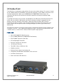
Product Views ................................................................................................................................. 11
Relio R9 Left .................................................................................................................................... 11
Relio R9 Right .................................................................................................................................. 11
Relio R9 Front .................................................................................................................................. 11
Block Diagram ................................................................................................................................. 12
Technical Description ........................................................................................................................ 13
Memory............................................................................................................................................ 13
Ethernet ........................................................................................................................................... 13
USB ................................................................................................................................................... 14
LCD and Touchscreen Controllers................................................................................................. 15
Serial Debugging ............................................................................................................................ 17
Serial Communications .................................................................................................................. 18
CAN Bus ........................................................................................................................................... 20
Optically Isolated Inputs ................................................................................................................ 21
Open Collector Outputs ................................................................................................................. 23
Analog Inputs .................................................................................................................................. 25
©Sealevel Systems, Inc.
SL9211 05/2015
Relio R9 Manual
2
Quadrature Counters...................................................................................................................... 27
Quadrature Counter 1 (Bottom connector) ................................................................................... 28
Quadrature Counter 2 (Top connector) ......................................................................................... 28
SD/MMC Cards ................................................................................................................................ 29
RS-485 Expansion ........................................................................................................................... 30
Power ............................................................................................................................................... 32
Software .............................................................................................................................................. 34
Relio R9 Quick Start ........................................................................................................................ 34
Windows Device Center .................................................................................................................. 36
Windows ActiveSync for XP ............................................................................................................ 37
Connection Complete ..................................................................................................................... 38
Application Development ............................................................................................................... 39
Application Debugging .................................................................................................................. 44
Introduction ..................................................................................................................................... 44
Requirements .................................................................................................................................. 44
Debugging an Application.............................................................................................................. 44
Attach the Debugger ...................................................................................................................... 45
Breakpoints...................................................................................................................................... 47
Watching Variables ......................................................................................................................... 49
Target Deployment and Execution ................................................................................................ 50
SDCARD Boot Sequence ................................................................................................................. 51
OS File Restoration ......................................................................................................................... 51
Using the Debug Port ..................................................................................................................... 51
Upgrading the OS Runtime Image on SDCARD ............................................................................ 56
Memory Card Reader ...................................................................................................................... 56
USB Connection: Using Windows Mobile Device Center or ActiveSync ....................................... 58
FTP Connection ............................................................................................................................... 60
Upgrading the OS Runtime Image on NAND Flash ...................................................................... 64
Network Configuration ................................................................................................................... 67
<Configuration> -Structure ............................................................................................................ 68
<System> -Structure........................................................................................................................ 68
<Ethernet> - Structure .................................................................................................................... 69
<Sealevel> - Structure ..................................................................................................................... 70
<User> - Structure ........................................................................................................................... 70
<Action> - Writeonly [string] .......................................................................................................... 70
Specifications ..................................................................................................................................... 71
Dimensions ..................................................................................................................................... 71
Power ............................................................................................................................................... 71
©Sealevel Systems, Inc.
SL9211 05/2015
Relio R9 Manual
3
Environmental Specifications ......................................................................................................... 71
Manufacturing ................................................................................................................................. 71
Appendix A – Resources ..................................................................... Error! Bookmark not defined.
Books ................................................................................................ Error! Bookmark not defined.
Web Sites .......................................................................................... Error! Bookmark not defined.
Appendix B – Relio R9 Internal Connector Reference ..................................................................... 73
Appendix C – Application Debugging over Ethernet ....................................................................... 74
Appendix D – CAD Drawing .............................................................................................................. 76
Appendix E – How to Get Assistance ................................................................................................ 77
Technical Support ........................................................................................................................... 77
Warranty.............................................................................................................................................. 78
Warranty Policy ............................................................................................................................... 78
Non-Warranty Repair/Retest .......................................................................................................... 78
How to obtain an RMA (Return Merchandise Authorization)....................................................... 78
Trademarks ..................................................................................................................................... 78
©Sealevel Systems, Inc.
SL9211 05/2015
Relio R9 Manual
4
ESD Warnings
ELECTROSTATIC DISCHARGES (ESD)
A sudden electrostatic discharge can destroy sensitive components. Proper packaging and
earthing rules must therefore be observed. Always take the following precautions.
•
Transport boards and cards in electrostatically secure containers or bags.
•
Keep electrostatically sensitive components in their containers, until they arrive at an
electrostatically protected workplace.
•
Only touch electrostatically sensitive components when you are properly earthed.
•
Store electrostatically sensitive components in protective packaging or on anti-static
mats.
GROUNDING METHODS
The following measures help to avoid electrostatic damages to the device:
•
Cover workstations with approved antistatic material. Always wear a wrist strap
connected to workplace as well as properly grounded tools and equipment.
•
Use antistatic mats, heel straps, or air ionizers for more protection.
•
Always handle electrostatically sensitive components by their edge or by their casing.
•
Avoid contact with pins, leads, or circuitry.
•
Turn off power and input signals before inserting and removing connectors or
connecting test equipment.
•
Keep work area free of non-conductive materials such as ordinary plastic assembly aids
and Styrofoam.
•
Use field service tools such as cutters, screwdrivers, and vacuum cleaners which are
conductive.
•
Always place drives and boards PCB-assembly-side down on the foam.
©Sealevel Systems, Inc.
SL9211 05/2015
Relio R9 Manual
5
Introduction
The Relio R9 is an application-ready platform for your next product design. The system is based
on the 200MHz Atmel AT91SAM9263 microcontroller boasting a 32-bit ARM® instruction set for
maximum performance. With up to 256MB RAM and 256MB NAND Flash memory, the
unmatched I/O features of the Relio R9 extend the possible uses beyond traditional ARM
applications.
To provide the fastest time to market, the Windows CE 6.0 BSP binary and low-level drivers for
system I/O are included. Additionally, the Relio R9 software package is equipped with the
Sealevel Talos I/O Framework, which offers a high-level object-oriented .NET Compact
Framework (CF) device interface. This interface provides an I/O point abstraction layer with
built-in support for the specific needs of analog and digital I/O such as gain control and
debouncing.
The Relio R9 is housed in a rugged, small enclosure suitable for mounting almost anywhere and
is rated for a full -40° – +85°C operating temperature range. The Relio R9 is powered from your
7-30VDC source, or select from a variety of Sealevel power supply options.
FEATURES
•
Atmel AT91SAM9263 ARM® Processor
•
Up to 256MB SDRAM and 256MB NAND Flash Memory
•
Dual SD/MMC Expansion Card Slots
•
LCD and Backlight Controller
•
Resistive Touchscreen Controller
•
10/100 BaseT Ethernet
•
Two USB 2.0 Ports; USB Device Port
•
CAN Bus Interface
•
On-board Serial, Digital, and Analog I/O
•
Compatible with Windows Embedded CE 6.0 and Linux
•
Low Power Requirements
•
Power and Status LED Indicators
©Sealevel Systems, Inc.
SL9211 05/2015
Relio R9 Manual
6
Before You Get Started
WHAT’S INCLUDED
The Relio R9 is shipped with the following items. If any of these items are missing or damaged,
please contact Sealevel for replacement.
•
Relio R9 ARM9 Embedded RISC Single Board Computer
•
SD Card with CE runtime image, Talos .NET Framework, application samples, and
documentation
•
CD with Setup files and documentation
•
Microsoft® Windows® CE 6.0 Core license
ADVISORY CONVENTIONS
Warning - The highest level of importance used to stress a condition where damage
could result to the product or the user could suffer serious injury.
Important – The middle level of importance used to highlight information that might
not seem obvious or a situation that could cause the product to fail.
Note – The lowest level of importance used to provide background information,
additional tips, or other non-critical facts that will not affect the use of the product.
©Sealevel Systems, Inc.
SL9211 05/2015
Relio R9 Manual
7
QUICKSTART KIT
The Relio R9-KT QuickStart kit is available, which includes the most common accessories. For
applications with specialized hardware requirements, developers can use the Relio R9 as a
platform for application development while Sealevel designs a customized target system
specific to the user’s application requirements.
The Relio R9-KT includes the following items:
•
Relio R9 - ARM9 Embedded RISC Computer
•
SD Card with CE runtime image, Talos .NET Framework, application samples, and
documentation
•
CD with Setup files and documentation
•
Microsoft Windows CE 6.0 Core License
•
TR123 – 100-240VAC to 12VDC @ 2.5A, wall mount power supply
•
CA356 - USB Type A to SeaLATCH USB Type B, Device Cable
•
CA429 - R9 serial debug cable
•
CA246 - CAT5 patch cable, 6' length
©Sealevel Systems, Inc.
SL9211 05/2015
Relio R9 Manual
8
OPTIONAL ITEMS
Depending upon your application, you are likely to find one or more of the following items
useful with the Relio R9. All items can be purchased from our website (www.sealevel.com) by
calling our sales team at (864) 843-4343.
CABLES
USB Type A to USB Type B, 72" in Length - Device Cable (Item# CA179)
The CA179 is a 72" standard USB device cable that
connects USB peripherals with a Type B connector to the
Type A connector on a host computer. The CA179 is USB
2.0 compliant and is compatible with USB 1.1 and 1.0
devices.
CAT5 Patch Cable, 7' in Length – Blue (Item# CA246)
Standard 7' CAT5 UTP Patch Cable (RJ45).
R9 Serial Debug Cable, 72" in Length (Item# CA429)
The CA429 is a 72" serial debug cable with a 1x4
connector on one end and a standard DB9F connector on
the other end. The DB9F connector is compatible with
any standard RS-232 DB9M serial port.
POWER SUPPLY
100-240VAC to 12VDC @ 2.5A, Wall Mount Power Supply (Item# TR123)
The TR123 is a wall mount (wall wart style) power supply
rated for 100-240VAC input and 12VDC output at 2.5
amps. The 72" cable has tinned leads for use with
products that have screw terminals for input power. The
white line or printing on the insulation indicates positive
polarity.
©Sealevel Systems, Inc.
SL9211 05/2015
Relio R9 Manual
9
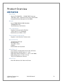
Product Overview
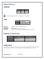
SPECIFICATIONS
PROCESSOR
Atmel (AT91SAM9263) — 200MIPS RISC Processor
16KB Data Cache, 16KB Instruction Cache, Write Buffer
Integrated Memory Management Unit (MMU)
MEMORY
Up to 256MB SDRAM (64MB Standard)
256MB NAND Flash
Two SD Memory Card Sockets
LCD CONTROLLER
Supports Passive or Active Displays
16-bit Color in TFT/STN Modes
Resolution Up to 2048 x 2048
TOUCHSCREEN CONTROLLER
Supports 5-wire Resistive Touchscreens
BUS INTERFACES
10/100 BaseT Ethernet
USB Device Port
Two USB 2.0 Ports
CAN Bus
Dedicated RS-485 Expansion
INDUSTRIAL I/O
Four Software Configurable RS-232/422/485 Ports
Eight Optically Isolated Inputs (5 – 24V)
Eight Open-Collector Outputs (5 – 30V; 3 with PWM)
Eight Analog Inputs (12-bit or 16-bit)
Two 32-bit Quadrature Counters
INDICATORS
Dual LED Indicators for Power and Status
©Sealevel Systems, Inc.
SL9211 05/2015
Relio R9 Manual
10
PRODUCT VIEWS
RELIO R9 LEFT
RELIO R9 RIGHT
RELIO R9 FRONT
©Sealevel Systems, Inc.
SL9211 05/2015
Relio R9 Manual
11
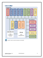
BLOCK DIAGRAM
See Appendix B for the Connector Reference Table, which details the connectors,
jumpers, and test points located on the Relio R9.
©Sealevel Systems, Inc.
SL9211 05/2015
Relio R9 Manual
12
Technical Description
MEMORY
The Relio R9 base configuration includes 64MB SDRAM and 256MB NAND Flash. For memory
intensive applications, the board can be ordered preconfigured with up to 256MB SDRAM.
ETHERNET
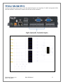
The Relio R9 includes a 10/100 BaseT Ethernet interface accessed via the RJ45 connector
located on the front of the enclosure.
The RJ45 port on the left side of the Relio R9 is a RS-485 Expansion Port (labeled “RS485 OUT”) and is NOT an Ethernet port. Damage to Ethernet networking equipment can
result if connected to the RS-485 RJ45 connector.
©Sealevel Systems, Inc.
SL9211 05/2015
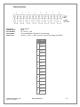
Pin
Signal
1
TX+
2
TX-
3
RX+
4
NC
5
NC
6
RX-
7
NC
8
NC
Relio R9 Manual
13
USB
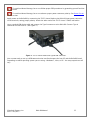
The Relio R9 provides two SeaLATCH USB 2.0 host ports, and one SeaLATCH USB device port.
The USB host ports are located on the left side of the enclosure. The USB device port is located
on the front of the enclosure.
Connector:
Manufacturer:
Description:
Mates with:
SeaLATCH USB 2.0 Host Port
Samtec
Standard USB Type A
SeaLATCH USB Type A, or Standard USB Type A
Connector:
Manufacturer:
Description:
Mates with:
SeaLATCH USB 2.0 Device Port
Samtec
Standard USB Type B
SeaLATCH USB Type B, or Standard USB Type B
©Sealevel Systems, Inc.
SL9211 05/2015
Relio R9 Manual
14
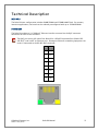
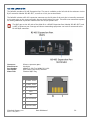
LCD AND TOUCHSCREEN CONTROLLERS
A variety of LCDs can be directly controlled by the Relio R9’s on-board LCD controller. All LCD
power and control signals are available on header connector P2. To access you will need to
remove the cover of the Relio R9.
Connector:
Manufacturer:
Part Number:
Description:
Mates with:
P2
Samtec
TFML-125-02-S-D
Locking terminal strip, 50 pos, 0.050” pitch
Samtec SFML-125-T2-S-D or Samtec TFMDL-25-T-03.00
©Sealevel Systems, Inc.
SL9211 05/2015
Relio R9 Manual
15
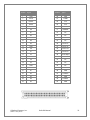
Position
Position
Signal
Signal
1
GND
26
GND
2
DCLK
27
LCDEN
3
HSYNC
28
3.3V
4
VSYNC
29
3.3V
5
GND
30
HDMODE
6
R0
31
VDMODE
7
R1
32
NC
8
R2
33
NC
9
R3
34
NC
10
R4
35
NC
11
R5
36
Touch UL
12
GND
37
Touch LL
13
G0
38
Touch UR
14
G1
39
Touch LR
15
G2
40
Touch Wiper
16
G3
41
NC
17
G4
42
NC
18
G5
43
NC
19
GND
44
NC
20
B0
45
LCDLED3
21
B1
46
GND
22
B2
47
LCDLED2
23
B3
48
GND
24
B4
49
LCDLED1
25
B5
50
GND
©Sealevel Systems, Inc.
SL9211 05/2015
Relio R9 Manual
16
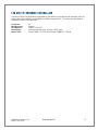
SERIAL DEBUGGING
Debug the R9 through the RS-232 debug port. To access you will need to remove the cover of
the Relio R9.
Connector:
Manufacturer:
Part Number:
Description:
J6
Amp/Tyco
9-146278-0-04
Header, 0.100” Polarized 4 pos, pin 3 Removed
©Sealevel Systems, Inc.
SL9211 05/2015
Pin
RS-232
1
RX
2
GND
3
Key
4
TX
Relio R9 Manual
17
SERIAL COMMUNICATIONS
Connect to a variety of serial peripherals via the Relio R9’s software configurable RS232/422/485 ports. The serial port interfaces are available on DB-9 male connectors. Serial 1
and Serial 2 ports are located on the front of the enclosure, and Serial 3 and Serial 4 ports are
located on the right side of the enclosure.
©Sealevel Systems, Inc.
SL9211 05/2015
Relio R9 Manual
18
Connectors:
Description:
Serial 1 – Serial 4
DB-9 Male
PIN
RS-232
RS-422/485
1
DCD
RX+
6
DSR
NC
2
RX
RX-
7
RTS
NC
3
TX
TX-
8
CTS
NC
4
DTR
TX+
9
RI
NC
5
GND
GND
COM Port Assignments
©Sealevel Systems, Inc.
SL9211 05/2015
Serial Port
Assignment
RS485 Expansion Port
COM1
SERIAL1
COM2
SERIAL2
COM3
SERIAL3
COM4
SERIAL4
COM5
Relio R9 Manual
19
CAN BUS
Connect directly to a Control Area Network (CAN) bus via the CAN connector on the left side of the
enclosure.
Connector:
Manufacturer:
Part Number:
Description:
Mates with:
CAN
Weco
110-M-111/04
Terminal Block 4 position 3.5mm spacing
Weco 110-A-111/04 4 position screw-terminal plug (provided)
Pin
Signal
H
CAN High
GND
©Sealevel Systems, Inc.
SL9211 05/2015
L
CAN Low
S
Shield
Relio R9 Manual
20
OPTICALLY ISOLATED INPUTS
Interface 8 optically isolated inputs. The non-polarized inputs can range from 5-24VDC and provide 300V
external isolation. Connection is made at on the front of the enclosure.
©Sealevel Systems, Inc.
SL9211 05/2015
Relio R9 Manual
21
Connector:
Manufacturer:
Part Number:
Description:
Mates with:
OPTO INPUTS
Weco
(2) 110-M-111/08
(2) Terminal Block 8 position 3.5mm spacing
(2) Weco 110-A-111/08 8 position screw-terminal plugs (provided)
Pin
Signal
Input 1A
1
Input 1B
Input 2A
2
Input 2B
Input 3A
3
Input 3B
Input 4A
4
Input 4B
Input 5A
5
Input 5B
Input 6A
6
Input 6B
Input 7A
7
Input 7B
Input 8A
8
Input 8B
©Sealevel Systems, Inc.
SL9211 05/2015
Relio R9 Manual
22
OPEN COLLECTOR OUTPUTS
Directly control eight outputs via the Relio R9’s open-collector outputs found on the front of the enclosure.
The open collector outputs have a range of 5 – 30V with a maximum sink current of 500mA on a single
output with a combined maximum sink current of 580mA on all outputs.
Connector:
Manufacturer:
Part Number:
Description:
Mates with:
OPEN-COLLECTOR OUTPUTS
Weco
110-M-111/10
Terminal Block 10 position 3.5mm spacing
Weco 110-A-111/10 10 position screw-terminal plug (provided)
©Sealevel Systems, Inc.
SL9211 05/2015
Relio R9 Manual
23
©Sealevel Systems, Inc.
SL9211 05/2015
Pin
Signal
0V
GND
1
Output 1 / PWM1
2
Output 2 / PWM2
3
Output 3 / PWM3
4
Output 4
5
Output 5
6
Output 6
7
Output 7
8
Output 8
Vin
OCVCC
Relio R9 Manual
24
ANALOG INPUTS
The Relio R9 base configuration includes a 12-bit ADC. Software programmable input ranges are 0V to 5V,
0V to 10V, ±5V or ±10V. Interface a variety of transducers and other analog signals via eight 12-bit analog
inputs located on the right side of the enclosure. For applications requiring higher resolution, the board can
be ordered preconfigured with a 16-bit A/D converter.
Connector:
Manufacturer:
Part Number:
Description:
Mates with:
ANALOG INPUTS
Weco
(2) 110-M-111/08
(2) Terminal Block 8 position 3.5mm spacing
(2) Weco 110-A-111/08 8 position screw-terminal plugs (provided)
©Sealevel Systems, Inc.
SL9211 05/2015
Relio R9 Manual
25
©Sealevel Systems, Inc.
SL9211 05/2015
Pin
Signal
1+
AIN1+
1-
AIN1-
2+
AIN2+
2-
AIN2-
3+
AIN3+
3-
AIN3-
4+
AIN4+
4-
AIN4-
5+
AIN5+
5-
AIN5-
6+
AIN6+
6-
AIN6-
7+
AIN7+
7-
AIN7-
8+
AIN8+
8-
AIN8-
Relio R9 Manual
26
QUADRATURE COUNTERS
High-speed input monitoring is accomplished with minimal software overhead using the two onboard 32-bit
quadrature counters. Both counters are available on the front of the enclosure, as two connectors labeled
“ENCODER”. The bottom connector is Quadrature Counter 1, and the top connector is Quadrature Counter
2. Input levels are LVTTL (0 – 3.6VDC).
Connector:
Manufacturer:
Part Number:
Description:
Mates with:
ENCODER
Weco
110-P-211/10
Terminal Block Dual Stacked 2 X 5 3.5mm
(2) Weco 110-A-111/10 5 position screw-terminal plugs (provided)
©Sealevel Systems, Inc.
SL9211 05/2015
Relio R9 Manual
27
QUADRATURE COUNTER 1 (BOTTOM CONNECTOR)
Pin
Signal
A
A
B
B
I
#INDEX
GND
3.3V
3.3VDC
QUADRATURE COUNTER 2 (TOP CONNECTOR)
Pin
Signal
A
A
B
B
I
#INDEX
GND
3.3V
©Sealevel Systems, Inc.
SL9211 05/2015
3.3VDC
Relio R9 Manual
28
SD/MMC CARDS
The Relio R9 provides two SD/MMC Card slots, Slot A and Slot B, located on the right side of the enclosure.
Each slot will accept standard-capacity SD/MMC Cards up to 2GB. SD/MMC Card slot A may be used for
booting.
To protect the SD/MMC Cards, a cover-plate is provided. To access the SD/MMC Cards, remove the two
screws then the cover plate.
©Sealevel Systems, Inc.
SL9211 05/2015
Relio R9 Manual
29
RS-485 EXPANSION
The Relio R9 provides a RS-485 Expansion Port. The port is available on the left side of the enclosure via the
RJ-45 connector labeled “RS-485 OUT”, as well as via a 4 pin terminal block.
The Relio R9 includes a RS-485 expansion connector on the left side of the unit that is internally connected
to the same pins on the screw terminals, also on the left side of the unit. This offers two convenient options
for adding additional expansion modules from the SeaI/O product line.
The RJ45 port on the left side of the Relio R9 is a RS-485 Expansion Port (labeled “RS-485 OUT”) and
is NOT an Ethernet port. Damage to Ethernet networking equipment can result if connected to the
RS-485 RJ45 connector.
Connector:
Manufacturer:
Part Number:
Description:
Mates with:
RS-485 Expansion (RJ45)
Xmultiple
XRJM-S-01-8-8-F2 or XRJM-S-01-8-8-0
RJ45 Socket, W/O LEDs, Shielded
Standard RJ45 Plug
Pin
Signal
1
9-30VDC Source
2
9-30VDC Source
3
Not connected
4
485+
5
485-
6
Not Connected
7
Common (GND)
8
Common (GND)
©Sealevel Systems, Inc.
SL9211 05/2015
8
Relio R9 Manual
1
30
Connector:
Manufacturer:
Part Number:
Description:
Mates with:
RS-485 Expansion
Weco
110-M-111/04
Terminal Block 4 position 3.5mm spacing
Weco 110-A-111/04 4 position
screw-terminal plug (provided)
©Sealevel Systems, Inc.
SL9211 05/2015
Pin
Signal
RS-485 (+)
485+
RS-485 (-)
485-
GND
Common (GND)
SHIELD
Shield (GND)
Relio R9 Manual
31
POWER
The Relio-R9 can be powered with the Sealevel TR134.
Connector:
Manufacturer:
Part Number:
Description:
Mates with:
9-30VDC Power Input
Weco
121-M-111/02
5.08mm Pitch Friction Lock Header
Weco 121-A-111/02
Be sure that you connect the power lead to the proper pin. Reversing the polarity of the power input
will damage your SBC-R9.
©Sealevel Systems, Inc.
SL9211 05/2015
Pin
Signal
1
9-30VDC
2
GND
Relio R9 Manual
32
LED INDICATORS
The SBC-R9 features two LED indicators for power and status. The Green LED (Top) is illuminated when
power is applied to the board. The Yellow LED (Bottom) is a GPIO controllable indicator accessible through
the TALOS API.
Designator:
Description:
D9
Dual Stacked LED Indicators
©Sealevel Systems, Inc.
SL9211 05/2015
LED
Color
Signal
Top
Green
Power
Bottom
Yellow
Status
Relio R9 Manual
33
Software
RELIO R9 QUICK START
Remove the contents from the box.
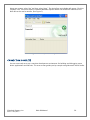
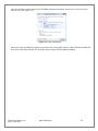
Insert the accompanying CD into your PC and run the installation program. This will install Talos Framework
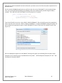
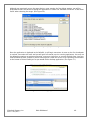
binaries, OS Runtime images, documentation, and examples on your PC.(See Figure 1.)
Figure 1. Installation Wizard
After installation, the package can be found in Windows by clicking Start All Programs Sealevel
Systems R9 Development.
Verify that the accompanying SD Card (located in SD/MMC Card Slot A of the Relio R9) is correctly inserted.
The contents of the SD Card will allow the Relio R9 to run Windows CE 6.0 OS when power is applied to the
board.
©Sealevel Systems, Inc.
SL9211 05/2015
Relio R9 Manual
34
To avoid accidental damage, be sure to follow proper ESD procedures by grounding yourself and the
board.
To avoid accidental damage, be sure to observe proper power connector polarity. See Power Pin-out
section.
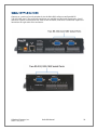
Apply power to the Relio R9 by connecting the TR123 tinned leads to the Relio R9 input power connector
screw terminals, noting proper polarity. Attach the other end of the TR123 into a 120VAC wall outlet.
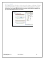
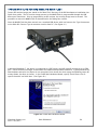
Use a standard USB device cable and connect the Type B connector to the Relio R9. Connect Type A
connector into the host PC. (See Figure 2.)
Figure 2. TR123 tinned leads and Type B USB connector.
You are now ready to set up a USB communication interface between the host PC and the Relio R9 board.
Depending on which operating system you are using – Windows 7, Vista, or XP – the setup experience will
vary.
©Sealevel Systems, Inc.
SL9211 05/2015
Relio R9 Manual
35
WINDOWS DEVICE CENTER
If your host PC is running Windows Vista or later and you are connected to the Internet, then Windows
Mobile Device Center software will install automatically. If you are not connected to the Internet but
have obtained the Mobile Device Center software manually, then running their setup will achieve the
same result. (See Appendix A.)
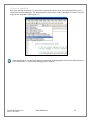
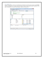
After installation, a negotiation will begin between the PC and the Relio R9 board and the device center
connection screen will appear. (See Figure 3.)
Figure 3. Device Center connected screen
Using your mouse, click “Connect without setting up your device”. The idea is to explore the file system
on the Relio R9 without setting up synchronization with contacts, calendar, or e-mail. Now choose “File
Management Browse the contents of your device” from the screen. (See Figure 4.)
Figure 4. Device Center File Management
©Sealevel Systems, Inc.
SL9211 05/2015
Relio R9 Manual
36
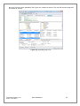
This action opens a standard Windows Explorer where the default file contents of the Relio R9 can be
read or written to. (See Figure 5.)
Figure 5. Contents of Relio R9
WINDOWS ACTIVESYNC FOR XP
If your host PC is running Windows XP, ActiveSync is required to establish connection to the Relio R9.
ActiveSync differs from Mobile Device Center in that having an internet connection will not establish an
automatic download and installation. For installation procedures, refer to Microsoft’s website. (See
Appendix A). After installation, a negotiation will begin between the PC and the Relio R9 board, and the
“New Partnership” dialog will appear. (See Figure 6.)
Figure 6. ActiveSync New Partnership screen
©Sealevel Systems, Inc.
SL9211 05/2015
Relio R9 Manual
37
Using your mouse, select “No” and then select “Next”. The ActiveSync main dialog will appear. Click the
“Explore” icon. This action opens a standard Windows Explorer where the default file contents of the
Relio R9 can be read or written. (See Figure 7.)
Figure 7. ActiveSync Main Dialog screen
CONNECTION COMPLETE
You are now ready to set up a complete development environment for building and debugging smart
device applications and libraries. The next section guides you by example using Microsoft Visual Studio.
©Sealevel Systems, Inc.
SL9211 05/2015
Relio R9 Manual
38
APPLICATION DEVELOPMENT
INTRODUCTION
With .NET Compact Framework coupled with our Talos .NET Framework, C# and VB.NET
programmers can develop powerful embedded applications on the Relio R9 such as mobile,
robotics, home automation, industrial, and a broad range of other embedded applications. The low
cost of licensing for Windows 6.0 CE has created an ideal environment to develop a new generation
of embedded products around the Relio R9.
Our Talos Framework allows access to the more specific I/O sections of the Relio R9 development
board such as analog and digital I/O points, CAN bus, quadrature counter inputs, and the multielectrical interface serial ports. A complete list of the API documentation can be found either in
Windows by clicking Start All Programs Sealevel Systems R9 Development Talos
Documentation.html.
Writing .NET applications for the Relio R9 is very similar to writing desktop or console applications
for Windows XP, Vista, and 7. The only difference is the amount of resources available. Because the
memory footprint is smaller compared to a desktop computer, care should be taken where
allocation of memory is concerned, such as large object creation.
REQUIREMENTS
• Visual Studio Professional 2005 or 2008
•
.NET Compact Framework 3.5
©Sealevel Systems, Inc.
SL9211 05/2015
Relio R9 Manual
39
GETTING STARTED
For this demonstration, we will construct a smart device console application using Visual C#. Start
Visual Studio and select File New Project. A ‘New Project’ dialog will appear. Select a project
type of Visual C# Smart Device. Select ‘Smart Device Project’ as the Template. Make sure the
combo box has .NET Framework 3.5 selected. Type the name of the project. In this case, call it
HelloWorld. (See Figure 8.)
Figure 8. Visual Studio New Project dialog
Click the "OK" button. The next configuration screen allows you to select the type of project you are
creating. Select "Windows CE" for the target platform, .NET Compact Framework version 3.5 and
select the "Console Application" icon for the template. (See Figure 9.)
Figure 9. Visual Studio Add Smart Device dialog
©Sealevel Systems, Inc.
SL9211 05/2015
Relio R9 Manual
40
Once you have selected all of the configuration options, click the "OK" button. You will now see a
console application template called HelloWorld in Visual Studio. (See Figure 10.)
Figure 10. Visual Studio Main Window
We can now add the references to the Talos Framework. Right click on the “References” and select
the "Add Reference…" selection. (See Figure 11.)
Figure 11. Adding References to Project
©Sealevel Systems, Inc.
SL9211 05/2015
Relio R9 Manual
41
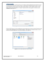
An ‘Add Reference’ dialog will appear. Click on the ‘Browse’ tab then search for the installed library
path “C:\Program Files\Sealevel Systems\R9 Development\Assemblies”. If you don’t see a list of the
R9 libraries as shown in Figure 12, then refer to the Relio R9 QuickStart section for software
installation details. While holding down the CTRL key, click on both "SLCorLib.dll" and "Talos.dll".
Click the “OK” button. (See Figure 12.)
Figure 12. Core library reference
Both DLLs should appear in your “References” list. (See Figure 13.)
Figure 13. Verification of added library references
©Sealevel Systems, Inc.
SL9211 05/2015
Relio R9 Manual
42
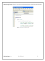
Now that the Talos Framework has been referenced, you have access to all the I/O points exposed on the
Relio R9 device.
For this simple HelloWorld application, we will just echo the string “Hello World” in the console window.
This can be accomplished by adding the following code to the automatically created Program::Main()
method. This code will echo “Hello World” and then pause for 5 seconds.
static void Main(string[] args)
{
Console.WriteLine("Hello World");
System.Threading.Thread.Sleep(5000);
}
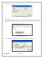
From Visual Studio’s menu bar, select “Build Build HelloWorld”. After the build process has completed
select from the same menu bar, “Build Deploy HelloWorld”. A “Deploy HelloWorld” dialog will appear for
you to choose the appropriate target. Choose “Windows CE Device” then press the ‘Deploy’ button. (See
Figure 14.)
Figure 14. Choose Windows CE Device and Deploy
After the deployment phase the “Hello World” message will appear on the Debug Serial console output.
Examples can be found from the installation directory under ‘..\R9 Development\Samples\C#’ and ‘..\R9
Development\Samples\VB.NET’.
©Sealevel Systems, Inc.
SL9211 05/2015
Relio R9 Manual
43
APPLICATION DEBUGGING
INTRODUCTION
This guide details the process of debugging an application developed for the Relio R9 embedded IO
system. The Relio R9 development platform easily integrates into standard Microsoft development tools
to make the debugging process extremely easy. The following sections detail the requirements to begin
debugging an application on Microsoft Windows 7, Vista, or XP.
REQUIREMENTS
•
Microsoft Mobile Device Center using Vista or ActiveSync using XP
•
Microsoft Visual Studio Professional 2005 or 2008
•
USB Cable or Ethernet connection
Debugging your Relio R9 applications is a simple process that requires a USB cable or Ethernet
connection, Microsoft device synchronization software, and Visual Studio. Depending on your version of
Windows, you will need to follow a different process to install the device synchronization software as
outlined in the Relio R9 Quick Start section.
DEBUGGING AN APPLICATION
Once the Relio R9 has been successfully attached to your PC, it is easy to begin debugging an
application on the Relio R9. This section will demonstrate how to attach the Microsoft Visual Studio
debugger to the Relio R9, show the use of breakpoints in the debugger, and show how to access useful
information while debugging an application.
We will be using the GPIO example application found in the "samples" directory of the Talos Framework
installation. The same methods will apply to any application you wish to debug on the Relio R9.
©Sealevel Systems, Inc.
SL9211 05/2015
Relio R9 Manual
44
ATTACH THE DEBUGGER
Once your solution is opened, it is necessary to specify the device target that you would like to use in
conjunction with the debugger. The default option is an emulator. Select "Windows CE Device" from the
target device drop down. (See Figure 15.)
Figure 15. Device Target Selection
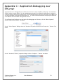
If you would like to use the faster Ethernet connection for debugging instead of the USB connection,
refer to Appendix C – Application Debugging over Ethernet.
©Sealevel Systems, Inc.
SL9211 05/2015
Relio R9 Manual
45
Now select the “Connect to Device” icon to initiate synchronization between Visual Studio and the Relio R9
device. (See Figure 16.)
Figure 16. Connect to Device icon
©Sealevel Systems, Inc.
SL9211 05/2015
Relio R9 Manual
46
You should now see a connection dialog appear. (See Figure 17.)
Figure 17. Connection Status Dialog
BREAKPOINTS
Setting breakpoints allows you to stop execution of your application at any point and examine the state
of the application. A breakpoint may be set by selecting a line and pressing the "F9" hotkey. (See Figure
18.)
Figure 18. Breakpoint selection
To begin debugging the application, click the "Start Debugging" button. (See Figure 19.)
Figure 19. Run Debugger icon
©Sealevel Systems, Inc.
SL9211 05/2015
Relio R9 Manual
47
Although you previously set up the target device, upon starting the first debug session, you will be
prompted to select the device to deploy the application to. Select the "Windows CE Device" as was done
earlier when selecting the target. (See Figure 20.)
Figure 20. Target Deployment dialog
Once the application is deployed to the Relio R9, it will begin execution. As soon as the first breakpoint
is reached, execution will cease and you will gain full control over the running application. You may use
the debugging options to continue execution, execute a single line, or execute multiple lines. You may
view the status of each variable by either hovering over it with the cursor or by examining the windows
at the bottom of Visual Studio just as you would with a desktop application. (See Figure 21.)
Figure 21. Examining program variables
©Sealevel Systems, Inc.
SL9211 05/2015
Relio R9 Manual
48
WATCHING VARIABLES
When program execution is halted due to a break point condition being met, the debugger will display
the state of all local variables. In addition to those variables, class specific variables can be grouped
together as a view to aid in debugging your application. This is accomplished by right clicking on a
variable and selecting "Add Watch". Each addition appends a tab to the “Watch n” window where n is
incremented for each variable added. (See Figure 22.) Each watch window provides a convenient tree
type structure for viewing hierarchical class variables.
Figure 22. Watch view
©Sealevel Systems, Inc.
SL9211 05/2015
Relio R9 Manual
49
TARGET DEPLOYMENT AND EXECUTION
After your application is built using Visual Studio, either a debug or release executable, it may be desirable
to copy it onto the SDCARD or NAND Flash. This would provide a means to store and execute your
application without the need for connectivity to a host computer. The first step is transferring your
application to a suitable directory on the SDCARD or on-board NAND Flash. To accomplish this you will
need to establish connectivity via Mobile Device Center or ActiveSync as outlined in the Relio R9 Quick Start
section above.
Figure 23. Application Placement
The Relio R9 Runtime image comes pre-loaded with a utility program called “SpringBoard”. This utility
provides a solution for automatically running your applications at startup. Rather than copying your
application files to ‘/Windows/Startup/’ - which is in volatile memory - the executables should be copied to
‘/Storage Card/startup/’ or `/nandflash/startup/’. After Windows CE runs, SpringBoard automatically starts
applications located in the NAND Flash followed by applications in the Storage Card.
SpringBoard also provides a way to specify program arguments by supplying an XML configuration file. You
will need to create a simple XML file called “startup.xml”. This XML file should consist of an element list
each with an application name and the desired arguments for that application. (See Figure 24.) This file
must reside in the following location: ‘/storage card/startup/startup.xml’ and/or
‘/nandflash/startup/startup.xml’.
If the startup.xml file is not found or is not desired, SpringBoard will still automatically run all the
applications placed in the aforementioned directory structure, only no arguments will be included
for those applications.
<?xml version="1.0" encoding="utf-8" ?>
- <programs>
<program name="sample1.exe" arguments="/i 1019 /w JSmith" />
<program name="sample2.exe" arguments="-e 2000" />
<program name="sample3.exe" arguments="/help" />
</programs>
Figure 24. startup.xml
©Sealevel Systems, Inc.
SL9211 05/2015
Relio R9 Manual
50
SDCARD BOOT SEQUENCE
Upon power up, the Relio R9 follows a specific boot sequence. The initial sequence is “firstboot”. The
firstboot process initializes the low level hardware and is responsible for loading the next sequence called
“eboot”. Eboot provides a configuration menu for setting connection types and start up memory locations.
Connection types include Ethernet and USB. Memory locations include SDCARD and NAND Flash. Ultimately,
eboot attempts to load and execute the OS runtime image based on those configuration settings.
The Relio R9 development board checks the root directory of the bottom SDCARD for a valid Eboot boot
loader (boot.bin). The file must be named boot.bin and the SDCARD must be formatted as FAT 12/16/32. If
no boot image is found, the device will next check the raw data in the NAND Flash.
Only the bottom SDCARD slot (Slot A) or NAND Flash can be used for booting to an OS runtime
image.
The Relio R9 ships with an SDCARD loaded with the OS files listed below:
•
Boot.bin
•
Eboot.bin
•
NK.bin
OS FILE RESTORATION
In the event that Sealevel produces updated OS file versions or a backup is desired, the OS files will need to
be copied to the root directory of an SDCARD or programmed to the NAND Flash. There are a variety of
ways to copy files to the SDCARD; please see the section labeled “Upgrading the OS runtime image on
SDCARD” below for more detail. Please see the section labeled “Upgrading the OS runtime image on NAND
Flash” for further detail into that process. The NAND Flash cannot be programmed until any existing OS
runtime image has been removed and the SDCARD is removed or the OS image on it is removed.
USING THE DEBUG PORT
This procedure requires an available RS-232 COM port or USB to RS-232 serial port adapter attached to a
host PC, a Relio R9 Serial Debug cable (Item# CA429), and any telnet terminal client application such as
PuTTY (See Appendix A). For this procedure, we will demonstrate the use of PuTTY.
Connect the 4-pin keyed female end of the Relio R9 RS-232 cable into the Relio R9 connector (J6). To access
this connector you will need to remove the cover of the Relio R9 and locate the connector on the exposed
motherboard. Connect the DB9 end of the Relio R9 RS-232 cable into an available serial port on the host
PC.
©Sealevel Systems, Inc.
SL9211 05/2015
Relio R9 Manual
51
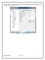
Run PuTTY and select “Serial” from the Category section of the dialog. Identify the proper COM port number
and always assign the speed (baud) equal to 115200. Set Data bits to 8, Stop bits to 1, Parity to None, and
Flow control to None. (See Figure 25.)
Figure 25. PuTTY Serial configuration
©Sealevel Systems, Inc.
SL9211 05/2015
Relio R9 Manual
52
Select “Session” from the Category section of the dialog. A saved session of this configuration can be
performed to avoid reconfiguration in the future. Next select Serial for the connection type. Type a name
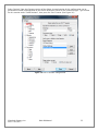
for this session under “Saved Sessions”, then press the “Save” button. (See Figure 26.)
Figure 26. PuTTY Session configuration
©Sealevel Systems, Inc.
SL9211 05/2015
Relio R9 Manual
53
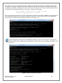
Press “Open” to start a new terminal session. A blank terminal window will appear. Debug messages may
not appear until power is applied to the Relio R9 board. Press the reset button on the Relio R9 to display
the Ethernet boot loader configuration screen. (See Figure 27.) When the unit boots, the following menu on
the debug port terminal will appear (no user input is required for booting):
“Press [ENTER] to download now or [SPACE] to cancel.
Initiating image download in 2 seconds"
Once the prompt period expires, the OS runtime will be loaded from SDCARD or NAND Flash (depending on
boot sequence and boot files available) into RAM and executed. At this point, the OS is running and all
console output is redirected to the debug serial port. (See Figure 27.)
Figure 27. Application Debug Text Output
Eboot configuration settings can be modified by hitting the “space” key during the 2 second boot
prompt period. When modifying the configuration, a menu such as the one below is displayed. (See
Figure 28.)
Figure 28. Eboot configuration output
©Sealevel Systems, Inc.
SL9211 05/2015
Relio R9 Manual
54
Modifying any of these settings may render your Relio R9 unbootable.
When upgrading an existing OS runtime stored in the NAND Flash, it is necessary to first erase the NAND
Flash of a pre-programmed unit. This is accomplished through the “Image flash menu” (‘n’ key) in Eboot.
The flash menu has an option to “Erase all sectors” of the NAND Flash (‘1’ key). (See Figure 29.)
Figure 29. Eboot Image Flash Menu
The “Erase all sectors” option in Eboot will erase the entire NAND Flash, so be sure to back up any
data you wish to save before attempting to erase the device.
©Sealevel Systems, Inc.
SL9211 05/2015
Relio R9 Manual
55
UPGRADING THE OS RUNTIME IMAGE ON SDCARD
Factory OS runtime images are stored in the “Boot Files” directory of the R9 Development installation (see
Quick start guide). There a few ways to upgrade the OS runtime image (*.bin) located on your bootable
SDCARD:
•
a memory card reader (preferred method)
•
USB connection with Windows Mobile Device Center or ActiveSync
•
FTP connection.
MEMORY CARD READER
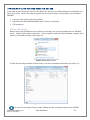
When inserting the SDCARD into your memory card reader, you may be prompted with an “AutoPlay”
option. Choose “Open folder to view files”. If the “AutoPlay” feature has been disabled, navigate to the
memory card reader manually. (See Figure 30).
Figure 30. AutoPlay screen
The OS runtime image consists of three binary (.bin) files as demonstrated below. (See Figure 31).
Figure 31. SDCARD File Contents
To save the existing OS runtime image, backup the files previously stored on the SDCARD.
©Sealevel Systems, Inc.
SL9211 05/2015
Relio R9 Manual
56
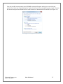
Copy the new OS runtime image to the SDCARD. A popup will appear asking you to override your
current files. Select the "Copy and Replace" option to over-write the existing OS runtime image. The new
OS runtime image will be loaded the next time the device is booted with the SDCARD. (See Figure 32.)
Figure 32. Copy and Replace
©Sealevel Systems, Inc.
SL9211 05/2015
Relio R9 Manual
57
USB CONNECTION: USING WINDOWS MOBILE DEVICE CENTER OR ACTIVESYNC
Another way to upgrade the OS runtime image is to connect via Windows Mobile Device Center or Active
Sync; for instructions on installing Windows Mobile Device Center or ActiveSync refer to the Relio R9
Quick Start section above.
Using the device file explorer, navigate to the “Storage Card” folder to view the SDCARD contents. (See
Figures 33/34.)
Figure 33. WindowsCE Device Explore
Figure 34. Storage Card contents
To save the existing OS runtime image, backup the SDCARD contents.
©Sealevel Systems, Inc.
SL9211 05/2015
Relio R9 Manual
58
Copy the new OS runtime image to the SDCARD. A popup will appear asking you to over-write your
current files. (See Figure 35.)
Figure 35. Copy and Replace
Select the "Copy and Replace" option to over-write the existing OS runtime image. Reboot the Relio R9
once the file has been copied. The new OS runtime image will be loaded on bootup.
©Sealevel Systems, Inc.
SL9211 05/2015
Relio R9 Manual
59
FTP CONNECTION
Use an FTP program to connect to the Relio R9 and upload the new OS runtime image to the SDCARD.
FileZilla (See Appendix A), an open-source FTP client, is used in the example below. By default, FTP is
open to anonymous access with no password needed. (See Figure 36.)
Figure 36. Connect to device through FTP
©Sealevel Systems, Inc.
SL9211 05/2015
Relio R9 Manual
60
Select the "Storage Card" folder for the remote site. (See Figure 37.)
Figure 37. Select Storage Card
©Sealevel Systems, Inc.
SL9211 05/2015
Relio R9 Manual
61
Navigate to the “Boot Files” directory of the R9 Development installation. Select the OS Runtime files to
copy (*.bin). Right-click and select “Upload” to begin the file transfer. (See Figure 38.)
Figure 38. Select boot files to update
You may be asked how to proceed when replacing existing files. Select the “Overwrite” radio button and
click “OK”. (See Figure 39.)
Figure 39. Over-write files
©Sealevel Systems, Inc.
SL9211 05/2015
Relio R9 Manual
62
Once the files have been uploaded, (See Figure 40.) reboot the device. The new OS runtime image will
be loaded on bootup.
Figure 40. Uploading boot files
©Sealevel Systems, Inc.
SL9211 05/2015
Relio R9 Manual
63
UPGRADING THE OS RUNTIME IMAGE ON NAND FLASH
Factory OS runtime images are stored in the “Boot Files” directory of the R9 Development installation (see
Quick start guide). The OS runtime image present in the NAND Flash is programmed through the USB
device port connection. Prior to programming an OS runtime, the existing image must be erased. The
procedure to erase the NAND Flash is documented in the Debug Port section.
Once the NAND Flash has been erased, use a standard USB device cable and connect the Type B connector
to the Relio R9. Connect Type A connector into the host PC. (See Figure 41.)
Figure 41. TR123 tinned leads and Type B USB connector
In Microsoft Windows 7, the device is recognized as a GPS camera and will typically enumerate as a COM
port. Check the device manager to determine the COM# associated with the device. If prompted with the
New Hardware wizard or the device is not recognized, then install the driver using the following steps (XP
menus shown, but Vista is similar). In the Found New Hardware Wizard, specify "Install from a list or
specific location" and click Next. (See Figure 42.)
Figure 42. Found New Hardware Wizard
©Sealevel Systems, Inc.
SL9211 05/2015
Relio R9 Manual
64
Select "Search for the best driver in these locations" and check "Include this location in the search". Use the
Browse button to browse to the “Utilities\SAM-BA\XP driver” directory of the R9 Development installation
and click “Next”.
The driver should be installed, and will come in as "AT91 USB to Serial Converter." Click Finish to complete.
(See Figure 43.)
Figure 43. Driver Installed
Determine COM port assignment using Device Manager > Ports. The USB function port should be listed.
For Windows 7, it may be listed as a GPS camera, otherwise it should be “AT91 USB to Serial Converter.”
Take note of the COM port assignment, to modify the programming batch file used to program the new OS
Runtime image. (See Figure 44.)
Figure 44. AT91 COM Port
©Sealevel Systems, Inc.
SL9211 05/2015
Relio R9 Manual
65
Sample scripts have been provided in the R9 Development installation to automate the process of writing a
complete OS runtime to the device. The script is configured to target a device attached to COM49 by
default. This can be modified simply by editing the comport variable in the “NAND Program.bat” batch file.
Once the batch file has been updated to reflect your system configuration, simply double-click the batch file
to begin the programming process. The process will take a few minutes. (See Figure 45).
Figure 45. Programming NAND (COM17)
Once programming has completed, cycle device power and the OS runtime should boot. (See Figure 46.)
Figure 46. Programming complete
As previously mentioned the process of programming the NAND Flash first erases all content from
the NAND Flash. This includes the unique MAC address assigned to your device at the factory. The
“finalize.exe” tool is provided in the “Boot Files” directory of the R9 Development installation.
Finalize is a command line utility that accepts a MAC address in dashed notation (00-0A-0B-16-1234). The application should be executed on the device after reprogramming the NAND Flash to
reassign the MAC address. Once the application has been executed, the setting is applied upon
device restart and persists.
©Sealevel Systems, Inc.
SL9211 05/2015
Relio R9 Manual
66
NETWORK CONFIGURATION
The Windows CE that runs on the Relio R9 is initially configured obtain its IP address via DHCP. Settings
may be required for DNS or WINS server IP addresses or if you want to set up a static IP address. We have
included an application in the OS that enables device configuration through a simple XML file format. The
configuration is stored in a file that is kept up-to-date on the NAND Flash of the device. Likewise, edits to
this file can be read as requests to modify the device’s configuration. The configuration file can be
accessed through ActiveSync using the USB device port connection or through an FTP client if you already
know the IP address of the device. This section defines the XML configuration structure and corresponding
values applicable for each element of the structure. Throughout this section the following definitions
apply:
Term
Definition
Example
[int]
A number
123
[String]
Series of printable characters
This is a test string!234567609
[Multi-line String]
strings separated by \r\n
A\r\nNew\r\nMulti-liner
[Version]
A version number
1.2.3.4
[Boolean]
A binary state
True / False
[MACAddress]
A hardware identifier
00-0A-0B-16-11-1A
[IPAddress]
An IPv4 network address
192.168.0.100
©Sealevel Systems, Inc.
SL9211 05/2015
Relio R9 Manual
67
The act of writing a new configuration file to the device will trigger a scan of that file (approximately
every 10 seconds). If the file is invalid, it will be replaced with the current configuration. If a single
element is invalid, that element and corresponding elements will be replaced with default values.
To apply a new configuration, use the <Action> element with a value of "apply" as documented
below.
Sample configuration.xml read from device.
<CONFIGURATION> -STRUCTURE
The configuration element is the root XML element. This element must be present or the configuration file
will not be considered valid. Invalid configurations will be replaced with a default configuration.
<SYSTEM> -STRUCTURE
The system element contains all of the system information elements. This element must be a child of
the Configuration element. This element must be present or the configuration file will not be
considered valid.
<OS> - READONLY [STRING]
The OS element contains a string representation of the Operating System name. This element must
be a child of the System element. In the case of R9 products, this will be equivalent to "WinCE".
<VERSION> - READONLY [VERSION]
The version element contains a dot-notation version string. This element must be a child of the
System element. This version is associated with the Operating System element.
<RUNTIME> - READONLY [STRING]
This element contains a string representation of the specific OS Runtime Image. This element must
be a child of the System element.
<RUNTIMEVERSION> - READONLY [VERSION]
This element contains a dot-notation version string. This element must be a child of the System
element. This version is associated with the OS Runtime Image.
©Sealevel Systems, Inc.
SL9211 05/2015
Relio R9 Manual
68
<PROCESSOR> - READONLY [STRING]
This element contains a Processor Identification string. This element must be a child of the System
element.
<NAME> - READ/WRITE [STRING]
This element may contain the device name string. This element must be a child of the System
element. This identifier is used as the WinCE host name.
<DESCRIPTION> - READ/WRITE [STRING]
This element may contain the device description string. This element must be a child of the System
element. This element can be used to further identify a device.
<OWNER> - READ/WRITE [STRING]
This element may contain a string that can be used to identify a person or department responsible
for maintaining a device. This element must be a child of the System element.
<COMPANY> - READ/WRITE [STRING]
This element may contain a string that can be used to identify the Company to which the device
Owner is associated. This element must be a child of the System element.
<ADDRESS> - READ/WRITE [MULTI-LINE STRING]
This element may contain a multi-line string (\r\n separated) to identify the location of the device
Owner. This element must be a child of the System element.
<PHONE> - READ/WRITE [STRING]
This element may contain a string representation of a telephone contact number for the device
Owner. This element must be a child of the System element.
<EXTENSION> - READ/WRITE [STRING]
This element may contain a string representation of a telephone extension for the device Owner.
This element must be a child of the System element.
<ETHERNET> - STRUCTURE
The Ethernet element contains a list of Ethernet interfaces available to the device. This element must be
a child of the Configuration element.
<INTERFACE NAME=""> - STRUCTURE (ATTRIBUTE READONLY [STRING])
The interface element is a container for the interface settings that are specific to the interface
identifiable as "name". This element must be a child of the Ethernet element. The name attribute
is readonly and is used to uniquely distinguish Interface settings for the case where there are
multiple Ethernet interfaces available.
<DHCP> - READ/WRITE [BOOLEAN]
This element contains a Boolean value indicating whether DHCP Address resolution is enabled or
disabled. This element must be a child of the Ethernet element. Valid values are True or False.
<MAC> - READONLY [MACADDRESS]
This element contains a dash delimited string containing the unique MAC address of this interface.
This element must be a child of the Ethernet element. The first 3 octets identify the device as a
Sealevel product (00-0A-0B). The fourth octet can be used to determine the product family (16).
And the last two octets will be unique for each device (11-1A).
<IPADDRESS> - READ/WRITE [IPADDRESS]
This element may contain the current DHCP acquired IP Address or the current static IP address
depending on the state of the DHCP element. This element must be a child of the Ethernet element.
Assigning a value to this element when DHCP is enabled has no effect.
©Sealevel Systems, Inc.
SL9211 05/2015
Relio R9 Manual
69
<SUBNET> - READ/WRITE [IPADDRESS]
This element may contain the current DHCP acquired Subnet Mask or the current static Subnet Mask
depending on the state of the DHCP element. This element must be a child of the Ethernet element.
Assigning a value to this element when DHCP is enabled has no effect.
<GATEWAY> - READ/WRITE [IPADDRESS]
This element may contain the current DHCP acquired Gateway address or the current static Gateway
address depending on the state of the DHCP element. This element must be a child of the Ethernet
element. Assigning a value to this element when DHCP is enabled has no effect.
<WIFI ENABLED=""> - STRUCTURE (ATTRIBUTE READONLY)
The Wifi element is a container for wireless bridge settings if such a bridge is present. This element
must be a child of the Ethernet element. The "enabled" attribute will reflect whether the Interface is
able to communicate with an approved wireless bridging module.
<SSID> - Read/Write [string]
This element contains the SSID string to be used when forming the wireless connection. This
element must be a child of the Wifi element.
<Mode> - Read/Write [string: Adhoc, Infrastructure]
This element contains the overall Wireless configuration mode. This element must be a child of
the Wifi element.
<Channel> - Read/Write [int: 1,11]
This element contains the wireless channel offset to use in Adhoc mode. This element must be
a child of the Wifi element.
<Security> - Read/Write [string: None, WepOpen64, WepOpen128, WepShared64,
WepShared128, WpaTkip, Wpa2Aes, Wpa2Tkip]
This element contains the security method for use in establishing the wireless connection. This
element must be a child of the Wifi element.
<Key encoding=""> Writeonly [string] (Attribute [string: Hex, Ascii, Pass])
This key is used to set the wireless connection passphrase or value. This element must be a
child of the Wifi element. Depending on the wireless configuration, the "encoding" attribute will
need to be set accordingly. For security purposes this value cannot be read once it has been set.
<SEALEVEL> - STRUCTURE
The Sealevel element contains a list of Sealevel internal configuration parameters used for Sealevel
supplied software plug-ins. This element must be a child of the Configuration element. The plug-in
application should contain documentation for the configuration parameters used by that plug-in.
<USER> - STRUCTURE
The User element can be used to contain a list of user configurable parameters for use in custom
software. This element must be a child of the Configuration element. Any elements stored under this
element will be automatically persisted to the registry key HKLM/Software/User. They can be accessed
through that key at any time by custom software.
<ACTION> - WRITEONLY [STRING]
This element may be used to trigger predetermined device behavior. This element must be a child of
the Configuration element. For example, setting a value of "apply" to this element will result in the
specified configuration being applied to the hardware and trigger a device restart so the settings will
take effect.
©Sealevel Systems, Inc.
SL9211 05/2015
Relio R9 Manual
70
Specifications
DIMENSIONS
Length
Width
Height
7.5”
5.1”
1.3”
For CAD drawing with dimensions, see Appendix D – CAD Drawing.
POWER
Connector:
Manufacturer:
Part Number:
Description:
Mates with:
Supply Line
7 – 30VDC Input
Rating
10 W Max (2.5W Nominal)
7 – 30VDC / GND on left side of enclosure
Weco
121-M-211/02
2 Position Right Angle 5.08mm Header
Weco 121-A-111/02 2 Position 5.08mm Pluggable Screw Terminal
ENVIRONMENTAL SPECIFICATIONS
Specification
Operating
Storage
Temperature Range
-40º to 85º C
-60º to 150º C
Humidity Range
10 to 90% R.H. Non-Condensing
10 to 90% R.H. Non-Condensing
MANUFACTURING
All Sealevel Systems printed circuit boards are built to UL 94V0 rating and are 100% electrically tested.
These printed circuit boards are solder mask over bare copper or solder mask over tin nickel.
©Sealevel Systems, Inc.
SL9211 05/2015
Relio R9 Manual
71
Appendix A – Resources
BOOKS
Professional Microsoft Windows Embedded CE 6.0, Wrox, Phung.
http://it-ebooks.info/book/1461/
Programming Windows Embedded CE 6.0 Developer Reference, Microsoft Press, Boling.
https://www.microsoft.com/learning/en-us/book.aspx?id=11064Web Sites
WEBSITES
Atmel SAM-BA In-System Programmer (ISP)
http://www.atmel.com/tools/atmelsam-bain-systemprogrammer.aspx
FileZilla Open-Source FTP Client
http://www.filezilla-project.org
Microsoft Windows Embedded Home Page
http://www.microsoft.com/windowsembedded/en-us/windows-embedded.aspx
Microsoft Windows Embedded CE 6.0 Online Documentation
https://msdn.microsoft.com/en-us/library/ee504812(v=winembedded.60).aspx
Microsoft ActiveSync Download
http://www.microsoft.com/windowsmobile/en-us/help/synchronize/ActiveSync-download.mspx
Microsoft Mobile Device Center 6.1
https://support.microsoft.com/en-us/kb/931937
Microsoft .NET Compact Framework
https://msdn.microsoft.com/en-us/library/ms376787.aspx
PuTTy Telnet/SSH Client Application
http://en.wikipedia.org/wiki/PuTTY
©Sealevel Systems, Inc.
SL9211 05/2015
Relio R9 Manual
72
Appendix B – Relio R9 Internal Connector
Reference
The following table details the connectors, jumpers, and test points located inside the Relio R9. To access
you will need to remove the cover of the Relio R9. The connectors, jumpers, and test points are labeled by
reference designator on the board silkscreen.
Reference Designator
Signal Description
P2
LCD, Backlight, and touchscreen controller
J6
RS-232 serial debug port
Jumpers
J1
Jumper - NAND Flash write protect
J2
Jumper - NAND Flash enable (Installed by default)
J4
Jumper - CAN Bus Termination (Installed by default)
J16
Jumper - Enable Push-button Reset (Installed by default)
Test Points
TP1
Test Point - Analog ground
TP2
Test Point - Received analog input
TP3
Test Point – Ground
TP4
Test Point – Ground
©Sealevel Systems, Inc.
SL9211 05/2015
Relio R9 Manual
73
Appendix C – Application Debugging over
Ethernet
Applications can be debugged over an Ethernet connection in place of USB by configuring Visual Studio to
directly connect to your device. For this method to work properly, the Ethernet connection to the device
must be properly configured to allow normal TCP/IP communications and you must know the IP address of
the device you wish to execute the application on. For further information about configuring the Ethernet
of the device see the Network Configuration section.
To configure Visual Studio to use your device for debugging over Ethernet, click the “Device Options”
button on the Device toolbar. See below.
On the “Device Options” dialog, select the “Windows CE” platform and click the “Properties…” button. See
below.
On the “Windows CE Device” properties dialog click the “Configure…” button. See below.
©Sealevel Systems, Inc.
SL9211 05/2015
Relio R9 Manual
74
Now click the “Use specific IP address” radio button and type the IP address of the device in the text box.
See below.
Click the “OK” button on all of the dialog windows and you should now be able to connect to the device
through Ethernet for debugging. The application debugging guide can be continued as normal.
©Sealevel Systems, Inc.
SL9211 05/2015
Relio R9 Manual
75
Appendix D – CAD Drawing
©Sealevel Systems, Inc.
SL9211 05/2015
Relio R9 Manual
76
Appendix E – How to Get Assistance
When calling for technical assistance, please have the device installed and ready to run diagnostics. If
possible, have your user manual and current settings ready.
The Sealevel website is an excellent resource located at www.sealevel.com. The most current software
updates and user manuals are available via our homepage by clicking on the 'Drivers' or 'Manuals' links
located under ‘Technical Support.’ Manuals and software can also be downloaded from the product page
for your device.
The FAQ section of our website answers many common questions. Refer to this helpful resource by visiting
www.sealevel.com/faq.asp.
TECHNICAL SUPPORT
Monday – Friday
8:00 am to 5:00 pm EST
Phone: +1 (864) 843-4343
Email: [email protected]
RETURN AUTHORIZATION MUST BE OBTAINED FROM SEALEVEL SYSTEMS BEFORE RETURNED
MERCHANDISE WILL BE ACCEPTED. AUTHORIZATION CAN BE OBTAINED BY CALLING SEALEVEL
SYSTEMS AND REQUESTING A RETURN MERCHANDISE AUTHORIZATION (RMA) NUMBER.
©Sealevel Systems, Inc.
SL9211 05/2015
Relio R9 Manual
77
Warranty
Sealevel's commitment to providing the best I/O solutions is reflected in the Lifetime Warranty that is
standard on all Sealevel manufactured I/O products. Relio™ industrial computers are warranted for a period
of two years and the Relio™/SeaPAC™ /SBC R9 family is warranted for a five year period from date of
purchase. We are able to offer this warranty due to our control of manufacturing quality and the historically
high reliability of our products in the field. Sealevel products are designed and manufactured at its Liberty,
South Carolina facility, allowing direct control over product development, production, burn-in and testing.
Sealevel achieved ISO-9001:2000 certification in 2002.
WARRANTY POLICY
Sealevel Systems, Inc. (hereafter "Sealevel") warrants that the Product shall conform to and perform in
accordance with published technical specifications and shall be free of defects in materials and
workmanship for the warranty period. In the event of failure, Sealevel will repair or replace the product at
Sealevel's sole discretion. Failures resulting from misapplication or misuse of the Product, failure to adhere
to any specifications or instructions, or failure resulting from neglect, abuse, accidents, or acts of nature
are not covered under this warranty.
Warranty service may be obtained by delivering the Product to Sealevel and providing proof of purchase.
Customer agrees to insure the Product or assume the risk of loss or damage in transit, to prepay shipping
charges to Sealevel, and to use the original shipping container or equivalent. Warranty is valid only for
original purchaser and is not transferable.
This warranty applies to Sealevel manufactured Product. Product purchased through Sealevel but
manufactured by a third party will retain the original manufacturer's warranty.
NON-WARRANTY REPAIR/RETEST
Products returned due to damage or misuse and Products retested with no problem found are subject to
repair/retest charges. A purchase order or credit card number and authorization must be provided in order
to obtain an RMA (Return Merchandise Authorization) number prior to returning Product.
HOW TO OBTAIN AN RMA (RETURN MERCHANDISE AUTHORIZATION)
If you need to return a product for warranty or non-warranty repair, you must first obtain an RMA number.
Please contact Sealevel Systems, Inc. Technical Support for assistance:
Available
Phone
Email
Monday – Friday, 8:00AM to 5:00PM EST
864-843-4343
[email protected]
TRADEMARKS
Sealevel Systems, Incorporated acknowledges that all trademarks referenced in this manual are the service
mark, trademark, or registered trademark of the respective company.
©Sealevel Systems, Inc.
SL9211 05/2015
Relio R9 Manual
78