1
ZapCode II Handbook
A Guide to
Electronic
ROM-code
Transmittal
ZapCode II Handbook
December 1995
Information in this document is provided in connection with Intel products. Intel assumes no liability whatsoever, including infringement of any patent or copyright, for sale and use of Intel products except as provided in Intel’s Terms and Conditions of
Sale for such products.
Intel retains the right to make changes to these specifications at any time, without notice. Microcontroller products may have
minor variations to this specification known as errata.
*Other brands and names are the property of their respective owners.
Contact your local Intel sales office or your distributor to obtain the latest specifications before placing your product order.
Copies of documents which have an ordering number and are referenced in this document, or other Intel literature, may be
obtained from:
Intel Corporation
Literature Sales
P.O. Box 7641
Mt. Prospect, IL 60056-7641
or call 1-800-879-4683
COPYRIGHT © INTEL CORPORATION, 1995
CONTENTS
CHAPTER 1
GUIDE TO THIS MANUAL
1.1
MANUAL CONTENTS ................................................................................................... 1-1
1.2
RELATED DOCUMENTS .............................................................................................. 1-2
1.3
ELECTRONIC SUPPORT SYSTEMS ........................................................................... 1-2
1.3.1
FaxBack Service .......................................................................................................1-2
1.3.2
Bulletin Board System (BBS) ....................................................................................1-3
1.3.3
CompuServe* Forums ..............................................................................................1-4
1.3.4
World Wide Web .......................................................................................................1-4
1.4
TECHNICAL SUPPORT ................................................................................................ 1-5
1.5
PRODUCT LITERATURE.............................................................................................. 1-5
CHAPTER 2
ZAPCODE II OVERVIEW
2.1
SOFTWARE OVERVIEW .............................................................................................. 2-1
2.2
HARDWARE AND SOFTWARE REQUIREMENTS ...................................................... 2-1
2.3
PROCESS OVERVIEW ................................................................................................. 2-1
CHAPTER 3
PRODUCT OPTIONS
3.1
PRODUCT NOMENCLATURE ...................................................................................... 3-2
3.2
NONVOLATILE MEMORY OPTIONS ........................................................................... 3-3
3.3
8-BIT EMBEDDED MICROCONTROLLER PRODUCTS .............................................. 3-5
3.3.1
Reference Tables ......................................................................................................3-5
3.4
16-BIT MICROCONTROLLER PRODUCTS ................................................................. 3-9
3.4.1
Reference Tables ......................................................................................................3-9
3.5
PACKAGE INFORMATION ......................................................................................... 3-12
CHAPTER 4
CODE SECURITY FEATURES
4.1
MEMORY PROTECTION OPTIONS FOR 8-BIT PRODUCTS ..................................... 4-2
4.1.1
Lock Bits ...................................................................................................................4-2
4.1.2
Encryption Array .......................................................................................................4-2
4.1.2.1
Creating an Encryption Array ...............................................................................4-3
4.1.3
Lock Bits and Encryption Array .................................................................................4-4
4.1.4
Programming Considerations ....................................................................................4-4
4.2
MEMORY PROTECTION OPTIONS FOR 16-BIT PRODUCTS ................................... 4-6
4.2.1
Security Key ..............................................................................................................4-6
4.2.2
CCB and PCCB Lock Bits .........................................................................................4-6
4.2.2.1
CCB Lock Bits ......................................................................................................4-7
4.2.2.2
PCCB Lock Bits ....................................................................................................4-7
4.2.3
UPROM Bits ..............................................................................................................4-8
4.2.4
Oscillator Failure Detection .......................................................................................4-8
iii
ZAPCODE II HANDBOOK
4.2.5
Programming Considerations ....................................................................................4-8
CHAPTER 5
SPECIFY THE PART MARKING
5.1
INTEL STANDARD PART MARKING............................................................................ 5-1
5.2
CUSTOMIZED PART MARKING................................................................................... 5-1
5.2.1
Determining Maximum Characters Per Line .............................................................5-2
CHAPTER 6
SELECT A PACKING METHOD
6.1
CARRIERS .................................................................................................................... 6-1
6.2
TAPE AND REEL .......................................................................................................... 6-1
6.3
TRAY ............................................................................................................................. 6-1
6.4
TUBE ............................................................................................................................. 6-2
6.5
WAFFLE PACK ............................................................................................................. 6-2
6.6
WAFER BOAT ............................................................................................................... 6-2
CHAPTER 7
INSTALL OR DELETE ZAPCODE II
7.1
INSTALLATION REQUIREMENTS ............................................................................... 7-1
7.2
CHOOSE AN INSTALLATION METHOD ...................................................................... 7-1
7.2.1
Boot Diskette Method ................................................................................................7-2
7.2.2
Multiple Boot Configuration Method ..........................................................................7-2
7.3
INSTALL THE ZAPCODE II SOFTWARE ..................................................................... 7-3
7.3.1
The ZapCode II Program Group ...............................................................................7-5
7.4
HOW TO USE THE ONLINE TRAINING COURSE....................................................... 7-5
7.5
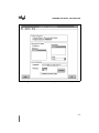
COMPLETE OR UPDATE THE INITIAL SETUP........................................................... 7-6
7.6
COMPLETE OR UPDATE THE CUSTOMER PROFILE AND PASSWORD ................ 7-9
7.6.1
Connect to Intel .........................................................................................................7-9
7.6.2
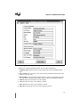
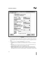
Complete the Customer Profile ...............................................................................7-10
7.6.3
Change Your Password ..........................................................................................7-12
7.7
HOW TO DOWNLOAD THE ZAPCODE II HANDBOOK............................................. 7-12
7.8
DELETE ZAPCODE II.................................................................................................. 7-13
7.8.1
Automated Method ..................................................................................................7-13
7.8.2
Manual Method .......................................................................................................7-14
CHAPTER 8
TRANSMIT AND VERIFY THE ROM CODE
8.1
START ZAPCODE II...................................................................................................... 8-1
8.1.1
Boot Disk Method ......................................................................................................8-1
8.1.2
Multiple Configuration Menu Method ........................................................................8-1
8.2
CREATE A CHECKSUM OPTIONAL) ........................................................................... 8-2
8.3
CONNECT TO INTEL .................................................................................................... 8-5
iv
CONTENTS
8.4
8.5
8.6
8.7
8.8
8.9
8.10
SELECT A PRODUCT AND PRODUCT FEATURES ................................................... 8-6
VERIFY YOUR PRODUCT SELECTION .................................................................... 8-11
TRANSMIT THE DATA TO INTEL............................................................................... 8-12
VERIFY THE CHECKSUM .......................................................................................... 8-16
RECORD THE ROM NUMBER ................................................................................... 8-17
EXIT ZAPCODE II ....................................................................................................... 8-17
EDIT THE FILES RETURNED FROM INTEL.............................................................. 8-18
CHAPTER 9
PLACE YOUR ORDER
APPENDIX A
PRODUCT ORDER FORM
APPENDIX B
ROM CODE HEX FILE DESCRIPTION
INDEX
v
ZAPCODE II HANDBOOK
FIGURES
Figure
3-1
4-1
4-2
4-3
5-1
7-1
7-2
7-3
7-4
8-1
8-2
8-3
8-4
8-5
8-6
8-7
8-8
8-9
8-10
8-11
8-12
8-13
8-14
vi
Page
Product Nomenclature..................................................................................................3-2
Sample Assembly Code (key.a51) for a 64-byte Encryption Array ..............................4-3
Sample ‘C’ Code (key.c) for a 64-byte Encryption Array ..............................................4-4
Sample Intel Hex Format File (key.hex) for a 64-byte Encryption Array ......................4-4
Intel Standard Part Mark Example................................................................................5-1
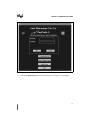
The ZapCode II Welcoming Screen .............................................................................7-7
Initial Setup Screen ......................................................................................................7-8
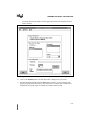
The ZapCode II Main Menu........................................................................................7-10
Example of a Completed Customer Profile Screen ....................................................7-11
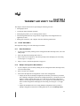
Product Information for Translation Screen - Without Security Feature .......................8-3
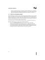
Product Information for Translation Screen - With Security Feature ............................8-4
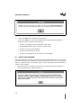
Example of a Path Message ........................................................................................8-5
Example of a Checksum Message ...............................................................................8-5
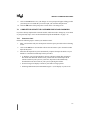
The ZapCode II Main Menu..........................................................................................8-6
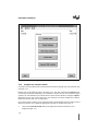
Example of a Product Information Screen....................................................................8-8
Example of a Product Screen With Only Standard Marking Showing ........................8-10
Example of a Part Marking Screen.............................................................................8-11
Transmit Data Window Example: Hex File Location Only ..........................................8-13
Transmit Data Window Example: Hex, Encryption, Configuration File Locations ......8-14
Transmit Data Window With ‘Replace Previous Code’ Selected................................8-15
Example of a ROM Code Path ...................................................................................8-16
Example of a Successful Checksum Message...........................................................8-16
Example of a ROM Number Message........................................................................8-17
CONTENTS
TABLES
Table
1-1
3-1
3-2
3-3
3-4
3-5
3-6
3-7
4-1
4-2
4-3
4-4
4-5
5-1
6-1
Page
Related Documents ......................................................................................................1-2
Description of Product Nomenclature...........................................................................3-2
Nonvolatile Memory Options and Descriptions.............................................................3-4
Commercial 8-bit Microcontroller Reference Guide......................................................3-6
Automotive 8-bit Microcontroller Reference Guide.......................................................3-8
Commercial 16-bit Microcontroller Reference Guide..................................................3-10
Automotive 16-bit Microcontroller Reference Guide...................................................3-11
Package Options ........................................................................................................3-12
Lock Bit Functions ........................................................................................................4-2
Encryption Truth Table .................................................................................................4-3
Memory Protection for Normal Operating Mode...........................................................4-7
ROM Protection with Authorized Program Verification.................................................4-7
Memory Protection Options for EPROM and OTPROM Programming Modes ............4-8
Part Marking Limits.......................................................................................................5-2
Tray Package Options ..................................................................................................6-2
vii
1
Guide to This Manual
CHAPTER 1
GUIDE TO THIS MANUAL
This manual describes the installation and use of ZapCode II, a software package that enables you
to transmit ROM code electronically to Intel. It also includes lists of available commercial and
automotive products.
This chapter describes what you’ll find in this manual, lists other documents that may be useful,
and explains how to access the support services we provide to help you complete your design.
1.1
MANUAL CONTENTS
This manual has 9 chapters, 2 appendixes, and an index.
This chapter, Chapter 1, provides an overview of the manual. This section summarizes the contents of the remaining chapters and appendixes. The remaining sections of this chapter provide
references to related documentation, describe customer support services, and explain how to access information and assistance.
• Chapter 2 — ZapCode II Overview — describes ZapCode II and the process for using it.
The chapter describes how to get started and lists the minimum hardware and software
requirements for using ZapCode II.
• Chapter 3 — Product Options — describes the available 8-bit and 16-bit microcontrollers
and features such as temperature and burn-in options and available package types.
• Chapter 4 — Code Security Features — contains security information for 8-bit and 16-bit
microcontrollers.
• Chapter 5 — Specify the Part Marking — contains the part-marking guidelines for your
device.
• Chapter 6 — Select a Packing Method — describes the packing methods available to
protect your product during shipment from the factory.
• Chapter 7 — Install or Delete ZapCode II — provides the instructions for installing and
deleting the ZapCode II software on your computer, for completing the Initial Setup, for
using the online training course, for completing and updating your Customer Profile, and
for downloading a copy of this manual.
• Chapter 8 — Transmit and Verify the ROM Code — provides the instructions for using
ZapCode II to transmit your ROM code to Intel, including checksum verifications before
and after the transmittal.
• Chapter 9 — Place Your Order — provides information for placing your order with your
Intel distributor or sales office.
• Appendix A — Product Order Form — contains a form that can be photocopied and used as
a checklist when preparing to order a product using ZapCode II.
1-1
ZAPCODE II HANDBOOK
• Appendix B — ROM Code Hex File Description — functionally describes a ROM-code
hex file.
• Index — lists key topics with page number references.
1.2
RELATED DOCUMENTS
Table 1-1 lists additional documents that you may find useful.
Table 1-1. Related Documents
Title and Description
Packaging manual
Shipping and Packaging data sheet
Automotive Handbook
Embedded Microcontrollers manual
8XC196KC/8XC196KD User’s Manual
8XC196Kx, 8XC196Jx, 87C196CA Microcontroller Family User’s Manual
8XC196NT Microcontroller User’s Manual
8XC196NP, 80C196NU User’s Manual
MCS® 48 Microcontroller Family User’s Manual
MCS® 51 Microcontroller Family User’s Manual
8XC51SA, 8XC51SB, 8XC51SP, 8XC51SQ Embedded Microcontroller Family User’s
Manual
Order Number
240800
240822
231792
270646
272238
272258
272317
272479
272382
272383
272795
In addition to the documents listed in Table 1-1, the U.S. Customer Literature Guide (order number 210620) and International Literature Guide (order number E00029) contain up-to-date lists
of literature related to Intel products. Refer to “Product Literature” on page 1-5 for ordering information.
1.3
ELECTRONIC SUPPORT SYSTEMS
Intel’s FaxBack* service and application BBS provide up-to-date technical information. We also
maintain several forums on CompuServe* and offer a variety of information on the World Wide
Web. These systems are available 24 hours a day, 7 days a week, providing technical information
whenever you need it.
1.3.1
FaxBack Service
FaxBack is an on-demand publishing system that sends documents to your fax machine. You can
get product announcements, change notifications, product literature, device characteristics, design recommendations, and quality and reliability information from FaxBack 24 hours a day, 7
days a week.
1-800-525-3019
U.S. and Canada
916-356-3105
U.S., Canada, Japan, Asia Pacific
+44-1793-432509
Europe
1-2
GUIDE TO THIS MANUAL
Think of the FaxBack service as a library of technical documents that you can access with your
phone. Just dial the telephone number and respond to the system prompts. After you select a document, the system sends a copy to your fax machine.
Each document is assigned an order number and is listed in a subject catalog. The first time you
use FaxBack, you should order the appropriate subject catalogs to get a complete listing of document order numbers.
Catalogs are updated twice monthly. In addition, daily update catalogs list the title, status, and
order number of each document that has been added, revised, or deleted during the past eight
weeks. The daily update catalogs are numbered with the subject catalog number followed by a
zero. For example, for the complete microcontroller and flash catalog, request document number
2; for the daily update to the microcontroller and flash catalog, request document number 20.
The following catalogs and information are available at the time of publication:
1.
Solutions OEM subscription form
2.
Microcontroller and flash catalog
3.
Development tools catalog
4.
Systems catalog
5.
Multimedia catalog
6.
Multibus and iRMX® software catalog and BBS file listings
7.
Microprocessor, PCI, and peripheral catalog
8.
Quality and reliability and change notification catalog
9.
iAL (Intel Architecture Labs) technology catalog
1.3.2
Bulletin Board System (BBS)
The bulletin board system (BBS) lets you download files to your computer. The application BBS
has the latest ApBUILDER software, hypertext manuals and datasheets, software drivers, firmware upgrades, application notes and utilities, and quality and reliability data.
916-356-3600
U.S., Canada, Japan, Asia Pacific (up to 19200 baud)
916-356-7209
U.S., Canada, Japan, Asia Pacific (2400 baud only)
44(0)1793-496340
Europe
The toll-free BBS (available in the U.S. and Canada) offers lists of documents available from
FaxBack, a master list of files available from the application BBS, and a BBS user’s guide. The
BBS file listing is also available from FaxBack (catalog number 6; see page 1-2 for phone numbers and a description of the FaxBack service).
1-800-897-2536
U.S. and Canada only
1-3
ZAPCODE II HANDBOOK
Any customer with a modem and computer can access the BBS. The system provides automatic
configuration support for 1200- through 19200-baud modems. Typical modem settings are 14400
baud, no parity, 8 data bits, and 1 stop bit (14400, N, 8, 1).
To access the BBS, just dial the telephone number and respond to the system prompts. During
your first session, the system asks you to register with the system operator by entering your name
and location. The system operator will set up your access account within 24 hours. At that time,
you can access the files on the BBS.
NOTE
If you encounter any difficulty accessing the high-speed modem, try the
dedicated 2400-baud modem. Use these modem settings: 2400, N, 8, 1.
1.3.3
CompuServe* Forums
The CompuServe forums provide a means for you to gather information, share discoveries, and
debate issues. Type “go intel” for access. For information about CompuServe access and service
fees, call CompuServe at 1-800-848-8199 (U.S.) or 614-529-1340 (outside the U.S.).
1.3.4
World Wide Web
NOTE
ZapCode II can now be downloaded over the Internet from Intel’s World
Wide Web site. Using this service will reduce from days to minutes the
time it takes to obtain the ZapCode II software and handbook. This
service is designed to increase your productivity by reducing the time it
takes to get your ROM code into production.
To access Intel’s Web site and download the ZapCode II software and handbook, follow these
steps:
1.
Start your browser, such as Netscape or Mosaic.
2.
Point your browser to the Intel home page (http://www.intel.com/).
3.
Select “Embedded Design Products” when the home page displays.
4.
Click on the Search button located at the bottom of the page (scrolling may be necessary).
5.
Perform a search using the keyword ZapCode.
6.
Download the software and the handbook when they are located.
At the time this handbook was published, the Intel Web site was being revised. The next version
of this handbook will provide more specific instructions for locating and downloading ZapCode
II. If you have any difficulty locating or downloading either the software or the handbook in the
interim, please contact your distributor or sales office for assistance.
1-4
GUIDE TO THIS MANUAL
1.4
TECHNICAL SUPPORT
In the U.S. and Canada, technical support representatives are available to answer your questions
between 5 a.m. and 5 p.m. PST. You can also fax your questions to us. (Please include your voice
telephone number and indicate whether you prefer a response by phone or by fax.) Outside the
U.S. and Canada, please contact your local distributor.
1-800-628-8686
U.S. and Canada
916-356-7599
U.S. and Canada
916-356-6100 (fax)
U.S. and Canada
1.5
PRODUCT LITERATURE
You can order product literature from the following Intel literature centers.
1-800-548-4725
U.S. and Canada
708-296-9333
U.S. (from overseas)
44(0)1793-431155
Europe (U.K.)
44(0)1793-421333
Germany
44(0)1793-421777
France
81(0)120-47-88-32
Japan (fax only)
1-5
2
ZapCode II Overview
CHAPTER 2
ZAPCODE II OVERVIEW
ZapCode II software is used to transmit your ROM code electronically to Intel. It is designed for
ease of use, and can reduce time-to-market by shrinking design and verification time for the product and the ROM code you have written for it. It also reduces administrative costs because the
software and the modem phone call are free. This chapter describes the software and the minimum hardware and software requirements to support it, and previews the ordering process.
2.1
SOFTWARE OVERVIEW
ZapCode II software is written in a Windows* software-based graphical user interface (GUI) design using Client SQL* Server technology.
The ZapCode II menu-driven software includes the following:
• a tutorial
• a field-sensitive help function
• an up-to-date electronic copy of this handbook
ZapCode II screens use prompts and field-sensitive help to guide you through the process of
transmitting your product order and code to Intel. The software includes an on-line training
course that lets you preview the ZapCode II software screens and learn how to interact with the
software.
2.2
HARDWARE AND SOFTWARE REQUIREMENTS
You must have the following minimum hardware and software to use ZapCode II:
•
•
•
•
an IBM AT-compatible personal computer with at least an Intel386TM microprocessor
2MB RAM memory
4MB of free hard drive space
a Hayes-compatible 2400 baud modem (9600 or higher recommended) installed on your
computer’s Com 1 or Com 2 port
• an analog telephone line (tone or dial)
• DOS software, version 6.x or greater
• Windows software, version 3.1 or greater
2.3
PROCESS OVERVIEW
ZapCode II software is used to transmit electronically your ROM code and any encryption and
configuration files that may be needed to Intel. As you fill in the menus, you identify the specific
product and product features you have chosen. This section provides an overview of how you use
2-1
ZAPCODE II HANDBOOK
the ZapCode software. The following chapters provide the detailed explanations and instructions
you will need.
The overview for using ZapCode II is as follows.
1.
Obtain the ZapCode II software in one of the two following ways.
• Order the ZapCode II Starter Kit from your Intel sales office or distributor.
• Download the ZapCode II Starter Kit from Intel’s World Wide Web site (see “World
Wide Web” on page 1-4).
2.
Select the product and the features for the product you want to order. You need this
information to complete the ZapCode II screens.
• Select a product. Chapter 3 lists available products and the following features.
— temperature and burn-in options
— package options
• Decide whether to enable security, if available. Chapter 4 describes code security
features.
• Select a marking format. Chapter 5 defines Intel’s standard and customized marking
guidelines.
• Select a packing method. Chapter 6 describes the packing methods available.
3.
Install ZapCode II on your computer. Chapter 7 provides the instructions you will need to
successfully install the software. It also includes instructions for using the ZapCode II
online training course and for downloading a copy of this handbook.
4.
Transmit your product information and your code to Intel. Chapter 8 provides the
instructions you will need to transmit the code and to verify that it was received error-free.
5.
Place your order with your local Intel sales office or distributor. Chapter 9 provides the
information you will need to complete a purchase order.
NOTE
Although Intel maintains your ROM code and mask for the duration of the
ordering and manufacturing process, they are not guaranteed to be maintained
for an extended period of time following order fulfillment. Intel recommends
that you archive your ROM code for future use in the event that it becomes
unavailable at Intel. In this event, should you place another order using the
same code, Intel will make another mask plate at no cost to you.
Use the steps in this procedure each time you want to order a product and transmit its ROM code
file to Intel. Since you must have this information readily available when you load ZapCode II
for transmittal, Intel recommends that you use a copy of Appendix A, “Product Order Form” to
record your product selection decisions.
2-2
3
Product Options
CHAPTER 3
PRODUCT OPTIONS
Use this chapter to select an embedded microcontroller product and a package option for it. If you
need additional information before making a selection, refer to the user’s manuals and datasheets
that describe the devices you are interested in (see “Related Documents” on page 1-2).
This chapter has five sections that you will use to select the product you want to order.
• “Product Nomenclature” on page 3-2 illustrates and describes the naming conventions for
Intel microcontrollers.
• “Nonvolatile Memory Options” on page 3-3 defines the nonvolatile memory options.
• “8-Bit Embedded Microcontroller Products” on page 3-5 lists the memory characteristics,
security features, and package options for 8-bit embedded microcontroller products.
• “16-Bit Microcontroller Products” on page 3-9 lists the memory characteristics, security
features, and package options for 16-bit embedded microcontroller products.
• “Package Information” on page 3-12 describes the packaging options available for
microcontroller devices.
3-1
ZAPCODE II HANDBOOK
3.1
PRODUCT NOMENCLATURE
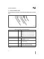
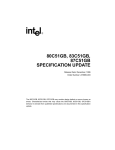
This section describes the nomenclature for the available microcontrollers. Figure 3-1 illustrates
the product nomenclature, while Table 3-1 describes the options and parameters for the nomenclature.
X
XX
8
X
X
XXXXX
XX
eS
ily
ed
pe
am
tF
uc
od
ns
on
tio
ati
rm
Op
ns
nfo
eI
in
n-
tio
Op
ur
ag
ry
ns
olt
dV
mo
tio
dB
an
Op
me
an
m-
ing
re
atu
ss
e
oc
ra
og
ag
vic
De
Pr
Pr
Pr
ck
er
mp
Pa
Te
A2815-02
Figure 3-1. Product Nomenclature
Table 3-1. Description of Product Nomenclature
Parameter
Temperature and Burn-in Options
Options
Commercial (–0° C to +70° C ambient) with standard
burn-in
T
Extended (–40° C to +85° C ambient) with standard
burn-in
L
Extended (–40° C to +85° C ambient) with extended
burn-in
A
Automotive (–40° C to +125° C case) with standard
burn-in
0†
3
7
No internal ROM
Internal ROM
Internal EPROM or OTPROM
Packaging Options
Program Memory Options
Process or Voltage Information
Description
No Mark
See “Package Information” on page 3-12
No Mark
C
CHMOS
Low voltage CHMOS
L
Product Family
Device Speed
†
3-2
196xx
A member of the MCS® 96 product family
51xx
A member of the MCS® 51 product family
251xx
A member of the MCS® 251 product family
No Mark
Standard speed
In the CMOS UPI and 8XC5x microcontroller families, a zero represents internal ROM. The three is not
used.
PRODUCT OPTIONS
3.2
NONVOLATILE MEMORY OPTIONS
Many Intel microcontrollers are available with several nonvolatile memory options. The memory
option that is most appropriate depends on lead-time constraints, minimum order quantities, cost,
availability, and your stage in the product development cycle. For example, you may want to use
an erasable programmable read-only memory (EPROM) option as you develop and debug your
code. After your code is stable and your design is in full production, it is more cost-effective to
switch to a read-only memory (ROM) option.
Table 3-2 defines the types of nonvolatile memory and includes information for minimum order
quantities, mask charges, and lead times. Tables 3-3 through 3-6 list the memory options for each
product. It is important to note that, while Intel offers a range of nonvolatile memory options for
its products, not all memory options are available for all products. Your Intel sales office or distributor can help you make the best choice for your needs based on cost and availability.
3-3
ZAPCODE II HANDBOOK
Table 3-2. Nonvolatile Memory Options and Descriptions
Memory Type
and Name
ROM
(Read-only
Memory)
FPROM
(Factoryprogrammed
OTPROM)
Description
• Intel programs the ROM with customer-specific code, usually
during the multi-layer masking process
2,000
$3,000
8 to 9
2,000
$3,000
8 to 9
500
$1,500
5 to 7
None
—
1 to 2
None
—
1 to 2
• Nomenclature example: P83C51FA,R XXXX
• Intel programs the OTPROM with customer-specific code
during the customer’s testing stage
• Used when the ROM mask has not been manufactured
• Nomenclature example: P87C51FA,R XXXX
QROM
• Intel programs the OTPROM with customer-specific code
(Quick Readonly Memory)
• Subject to availability
• Commercial nomenclature example: P8QC51FA,R XXXX
• Automotive nomenclature example: P87C51FA,R XXXX
EPROM
• You program the EPROM with your code
(Erasable
Programmable
Read-only
Memory)
• Usually packaged in ceramic with an ultraviolet (UV) window
to allow multiple programming and erasing
• Normally used by customers as follows:
— during the development stage when writing ROM code
— in the production stage for applications requiring multiple
erasing and programming
— for low-volume production runs
• Normally available “off the shelf”
• Nomenclature example: D87C51FA
OTPROM
• You program the OTPROM with your code
(One-time
Programmable
Read-only
Memory)
• OTPROM shares technology with EPROM
• Packaged in plastic
• Normally used by customers as follows:
— in the prototype stage of an embedded controller
application
— in an unstable or multiple-code environment
— for low-volume production runs
— when ROM products are not available
• Normally available “off the shelf”
• Nomenclature example: P87C51FA
†
3-4
Lead times in this column are estimates. Contact your local Intel distributor or sales office for a specific
product lead time.
PRODUCT OPTIONS
3.3
8-BIT EMBEDDED MICROCONTROLLER PRODUCTS
The high-performance, low-cost 8-bit microcontrollers included here are the CMOS UPI microcontroller families, the CMOS MCS 51 microcontroller families, and the CMOS MCS 251 microcontroller family.
Intel also has a large offering of 8-bit microcontrollers that are ideally suited for various automotive applications such as anti-lock braking systems (ABS) and engine control. Most of the information in this section applies to both commercial and automotive ROM products; however, there
are a few differences, which are detailed in Table 3-4. The Automotive Products handbook (literature order number 231792) contains product details.
For all 8-bit microcontrollers, your code must begin at 0000H (FF0000H for the 8XC251Sx). For
microcontrollers that have encryption arrays, your encryption file must also begin at 0000H
(FF0000H for the 8XC251Sx). See the 8XC251SA, 8XC251SB, 8XC251SP, 8XC251SQ Embedded Microcontroller User’s Manual for information about the starting address for the configuration file. Certain features of the 8XC251Sx family are configurable at reset.
3.3.1
Reference Tables
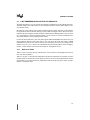
Tables 3-3 and 3-4 list the memory characteristics, security features, and package options of Intel’s 8-bit microcontrollers.
Table 3-1 on page 3-2 describes the temperature and burn-in options that are available for some
products. Refer to the data sheet for the product you have selected to obtain information on burnin availability. If you have questions on temperature and burn-in options, please contact your distributor or local sales office.
3-5
ZAPCODE II HANDBOOK
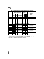
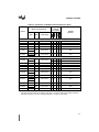
Table 3-3. Commercial 8-bit Microcontroller Reference Guide
Memory Characteristics
Security
Features†††
(X = present)
Package
Options††
Device
Type
Size
Code Range
80C42
ROM
4K
0000–0FFFH
X
—
—
P40, N44
87C42
EPROM
4K
0000–0FFFH
X
—
—
P40, N44, S44
CMOS UPI Microcontrollers
CMOS MCS® 51 Microcontrollers — 8XC5x Family
80C51BH
ROM
4K
0000–0FFFH
X
—
X
80C51BHP
ROM
4K
0000–0FFFH
X
—
X
P40, D40, N44, S44
EPROM
4K
0000–0FFFH
X
—
X
P40, D40, N44, S44
8K
0000–1FFFH
16K
0000–3FFFH
32K
0000–7FFFH
87C51
80C52
ROM
87C52
EPROM
80C54
ROM
87C54
EPROM
80C58
ROM
87C58
EPROM
P40, D40, N44, S44
X
—
X
P40, N44, S44
X
X
X
P40, D40, N44, S44
X
—
X
P40, N44, S44
X
X
X
P40, D40, N44, S44
X
—
X
P40, N44, S44
X
X
X
P40, D40, N44, S44
CMOS MCS® 51 Microcontrollers — 8XC51Fx, 8XC51GB, 8XC51KB, 8XC51SL, 8XC152 Family
83C51FA
ROM
87C51FA
EPROM
83C51FB
ROM
87C51FB
EPROM
83C51FC
ROM
87C51FC
EPROM
83C51GB
ROM
87C51GB
EPROM
83C51KB
ROM
83C51SLAH
ROM
87C51SLAH
EPROM
83C51SLAL
ROM
87C51SLAL
EPROM
83C152JA
ROM
8K
0000–1FFFH
16K
0000–3FFFH
32K
0000–7FFFH
8K
0000–1FFFH
4K
0000–0FFFH
16K
0000–3FFFH
16K
0000–3FFFH
8K
0000–1FFFH
X
—
X
P40, N44, S44
X
X
X
P40, D40, N44, S44, TS
X
—
X
P40, N44, S44
X
X
X
P40, D40, N44, S44
X
—
X
P40, N44, S44
X
X
X
P40, D40, N44, S44
X
—
X
N68
X
X
X
N68
—
—
—
P40
—
—
—
KU100
—
—
—
KU100
—
—
—
SB100
—
—
—
SB100
—
—
—
P48, N68
†
The 8XC251Sx microcontroller’s encryption array is 128 bytes, rather than 64 bytes.
††
The alpha character indicates the package designator. The number following the package designator
indicates the number of pins. See “Package Information” on page 3-12 for details.
†††
See Chapter 4, “Code Security Features,” for security information.
3-6
PRODUCT OPTIONS
Table 3-3. Commercial 8-bit Microcontroller Reference Guide (Continued)
Memory Characteristics
Security
Features†††
(X = present)
Package
Options††
Device
Type
Size
Code Range
Low-voltage CMOS MCS® 51 Microcontrollers — 8XL5x, 8XL51Fx Family
87L52
EPROM
8K
0000–1FFFH
X
X
X
N44, S44
87L54
EPROM
16K
0000–3FFFH
X
X
X
N44, S44
87L58
EPROM
32K
0000–7FFFH
X
X
X
N44, S44
87L51FA
EPROM
8K
0000–1FFFH
X
X
X
N44, S44
87L51FB
EPROM
16K
0000–3FFFH
X
X
X
N44, S44
87L51FC
EPROM
32K
0000–7FFFH
X
X
X
N44, S44
CMOS MCS® 251 Microcontrollers — 8XC251Sx Family
83C251SA
87C251SA
83C251SB
87C251SB
83C251SP
87C251SP
83C251SQ
87C251SQ
ROM
EPROM
8K
FF0000–FF1FFFH
16K
FF0000–FF3FFFH
8K
FF0000–FF1FFFH
16K
FF0000–FF3FFFH
X
—
X†
X
X
X†
X
—
X†
X
X
X†
X
—
X†
X
X
X†
X
—
X†
X
X
X†
C40, N44, P40
OTPROM
ROM
EPROM
C40, N44, P40
OTPROM
ROM
EPROM
C40, N44, P40
OTPROM
ROM
EPROM
C40, N44, P40
OTPROM
†
The 8XC251Sx microcontroller’s encryption array is 128 bytes, rather than 64 bytes.
††
The alpha character indicates the package designator. The number following the package designator
indicates the number of pins. See “Package Information” on page 3-12 for details.
†††
See Chapter 4, “Code Security Features,” for security information.
3-7
ZAPCODE II HANDBOOK
Table 3-4. Automotive 8-bit Microcontroller Reference Guide
Memory Characteristics
Security
Features
(X = present)
Package
Options†
Device
Type
Size
Code Range
CMOS MCS® 51 Microcontrollers — 8XC5x Family
80C51BH
ROM
4K
0000–0FFFH
—
—
—
P40, N44
80C51BHP
ROM
4K
0000–0FFFH
X
—
—
P40, N44
87C51
EPROM
4K
0000–0FFFH
X
X
X
P40, N44
87C54
EPROM
16K
0000–3FFFH
X
X
X
P40, N44
CMOS MCS® 51 Microcontrollers — 8XC51Fx Family
83C51FA
ROM
8K
0000–1FFFH
—
—
—
P40, N44
87C51FA
EPROM
8K
0000–1FFFH
X
X
X
P40, N44
87C51FB
EPROM
16K
0000–3FFFH
X
X
X
P40, N44
87C51FC
EPROM
32K
0000–7FFFH
X
X
X
P40, N44
†
3-8
The alpha character indicates the package designator. The number following the package designator
indicates the number of pins. See “Package Information” on page 3-12 for details.
PRODUCT OPTIONS
3.4
16-BIT MICROCONTROLLER PRODUCTS
The high-performance 16-bit microcontrollers included here are members of the CMOS MCS 96
microcontroller families.
Intel also has a large offering of 16-bit microcontrollers that are ideally suited for various automotive applications such as anti-lock braking systems (ABS) and engine control. Most of the information in this section applies to both commercial and automotive ROM products; however,
there are a few differences, which are detailed in Table 3-6. The Automotive Products handbook
(literature order number 231792) contains product details.
For 16-bit microcontrollers, your code must begin at 2000H (FF2000H for devices with extended
addressing).
3.4.1
Reference Tables
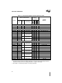
Tables 3-5 and 3-6 list the memory characteristics, security features, and package options of Intel’s 16-bit MCS 96 microcontrollers.
Table 3-1 on page 3-2 describes the temperature and burn-in options that are available for some
products. Refer to the data sheet for the product you have selected to obtain information on burnin availability. If you have questions on temperature and burn-in options, please contact your distributor or local sales office.
3-9
ZAPCODE II HANDBOOK
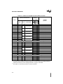
Table 3-5. Commercial 16-bit Microcontroller Reference Guide
Memory Characteristics
Security
Features†††
(X = present)
Device
Type
Size
Package
Options††
Code Range
CMOS MCS® 96 Microcontrollers — 8XC196KB, KC, KD Family
83C198
87C198-16
83C196KB
87C196KB16
ROM
OTPROM
ROM
OTPROM
83C196KC
ROM
87C196KC
OTPROM
83C196KC20
ROM
87C196KC20
OTPROM
83C196KD
ROM
87C196KD
OTPROM
8K
2000–3FFFH
8K
2000–3FFFH
16K
2000–5FFFH
16K
2000–5FFFH
32K
2000–9FFFH
32K
2000–9FFFH
X
X
—
—
N52, S80
X
X
X
—
N52, S80
X
X
—
—
N68, S80
X
X
X
—
N68, S80
X
X
X
—
N68, S80, SB80
X
X
X
X
N68, S80, SB80
X
X
—
—
N68, S80, SB80
X
X
X
X
N68, S80, SB80
X
X
—
—
N68, S80, SB80
X
X
X
X
N68, S80, SB80
X
X
—
—
N68, S80, SB80
X
X
X
X
N68, S80, SB80
83C196KD20
ROM
87C196KD20
OTPROM
87C196MC
OTPROM
16K
2000–5FFFH
X
X
X
X
N84, S80, U64
87C196MD
OTPROM
16K
2000–5FFFH
X
X
X
X
N84, S80, U64
87C196MH
OTPROM
32K
2000–9FFFH
X
X
X
X
N84, S80, U64
CMOS MCS® 96 Microcontrollers — 8XC196MC, MD, MH Family
CMOS MCS® 96 Microcontrollers — 8XC196Kx, Jx, CA Family
87C196JQ†
OTPROM
87C196KQ†
OTPROM
87C196JR†
OTPROM
87C196KR†
OTPROM
87C196KT†
87C196CA†
12K
2000–4FFFH
X
X
X
X
X
X
X
X
N52
N68
X
X
X
X
N52
16K
2000–5FFFH
X
X
X
X
N68
OTPROM
32K
2000–9FFFH
X
X
X
X
N68
OTPROM
32K
2000–9FFFH
X
X
X
X
N68
CMOS MCS® 96 Microcontrollers — 8XC196Nx Family
87C196NT†
OTPROM
32K
FF2000–FF9FFFH
X
X
X
X
N68
83C196NP
ROM
4K
FF2000–FF2FFFH
— X
—
—
S100, SB100
83C196NU
ROM
48K
FF2000–FFDFFFH
— X
—
—
S100, SB100
†
This product also incorporates oscillator failure detection (OFD) circuitry.
††
The alpha character indicates the package designator. The number following the package designator
indicates the number of pins. See “Package Information” on page 3-12 for details.
†††
See Chapter 4, “Code Security Features” for security information.
3-10
PRODUCT OPTIONS
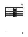
Table 3-6. Automotive 16-bit Microcontroller Reference Guide
Memory Characteristics
Security
Features
(X = present)
Device
Type
Size
Package
Options††
Code Range
CMOS MCS® 96 Microcontrollers — 8XC196EA Family
83C196EA
ROM
2000–3FFFH
X
X
X
—
S160
CMOS MCS® 96 Microcontrollers — 8XC196KB, KC, KD Family
83C196KB
ROM
8K
2000–3FFFH
X
X
—
—
N68
87C196KB12
ROM
8K
2000–3FFFH
X
X
—
—
N68
16K
2000–5FFFH
X
X
X
X
N68
32K
2000–9FFFH
X
X
X
X
N68
87C196KC
87C196KD
FPROM
OTPROM
FPROM
OTPROM
CMOS MCS® 96 Microcontrollers — 8XC196Kx, Jx, CA, CB Family
87C196KN
OTPROM
QROM
8K
2000–3FFFH
X
X
X
X
N84
X
X
X
X
N84
87C196KQ†
OTPROM
12K
2000–4FFFH
X
X
X
X
N68
87C196KR†
OTPROM
16K
2000–5FFFH
X
X
X
X
N68
87C196KS
OTPROM
24K
2000–7FFFH
X
X
X
X
N68
87C196KT†
OTPROM
32K
2000–9FFFH
X
X
X
X
N68
12K
2000–4FFFH
X
X
X
X
N52
16K
2000–5FFFH
X
X
X
X
N52
32K
2000–9FFFH
X
X
X
X
N52
48K
2000–DFFF4
X
X
X
X
N52
32K
2000–9FFFH
X
X
X
X
N68
56K
FF2000–FFFFFFH
X
X
X
X
N84, S100
87C196JQ†
87C196JR†
OTPROM
QROM
OTPROM
OTPROM
87C196JT†
QROM
ROM
87C196JV†
87C196CA
87C196CB
EPROM
OTPROM
QPROM
OTPROM
†
This product also incorporates oscillator failure detection circuitry.
††
The alpha character indicates the package designator. The number following the package designator
indicates the number of pins. See “Package Information” on page 3-12 for details.
3-11
ZAPCODE II HANDBOOK
3.5
PACKAGE INFORMATION
Intel has many options for packaging microcontroller devices. Table 3-7 describes several package types from which to make your selection. You must have this information available before
launching ZapCode II to place your order.
Not all package types are available for all devices. For additional information, refer to the “Package Options” column in the appropriate table of this chapter for the product you chose.
The Intel Packaging Handbook (literature order number 240800) includes more detailed package
information such as dimensions and performance characteristics.
Table 3-7. Package Options
Package
Designator
A
Ceramic Pin Grid Array (C-PGA)
B
Ceramic Land Grid Array (LGA)
C
CF
Ceramic Dual In-Line Package (CerDIP)
Ceramic Flat Package (FP)
D
Ceramic Dual In-Line Package (CerDIP)
E
Thin Small Outline Package, Die Up (TSOP)
F
Thin Small Outline Package, Die Down (TSOP)
FP
Plastic Flatpack Package (P-FP)
GB
Single In-Line Leaded Memory Module (SIP)
J
Cerquad Package (Cerquad)
K
Ceramic Quad Flatpack Package, Fine Pitch, Flat Leads (CQFP)
KD
Plastic Quad Flatpack Package, Fine Pitch, Die Down (PQFP)
KK
Ceramic Quad Flatpack Package, Fine Pitch, Formed Leads (CQFP)
KU
Plastic Quad Flatpack Package, Fine Pitch, Die Up (PQFP)
N
NG
Plastic Leaded Chip Carrier (PLCC)
Plastic Quad Flatpack, Fine Pitch, Die Down w/Heat Spreader (PQFP)
P
Plastic Dual In-Line Package (P-DIP)
PA
Small Outline “Gull Wing” Package (SOP)
PE
Small Outline “J” - Lead Package (SOJ)
Q
Ceramic Quad Flatpack Package (CQFP)
R
Ceramic Leadless Chip Carrier (LCC)
S
Quad Flatpack Package (QFP)
SB
3-12
Package Description
Square QFP (SQFP)
U
Shrink DIP
X
Unpackaged Devices
4
Code Security
Features
CHAPTER 4
CODE SECURITY FEATURES
Intel recognizes the importance of protecting customers’ code from unauthorized access to the
ROM contents. To help prevent unauthorized access, Intel has provided security features on
many of its microcontroller products. However, even though its developers have made a substantial effort to provide reliable program protection, Intel does not guarantee that these protection
methods will always prevent unauthorized access.
The following two sections of this chapter contain product security information for 8-bit and 16bit microcontrollers. While the user’s manual for the device you selected in Chapter 3 contains
the definitive information about that device, the information in this chapter can help you make
product decisions. You must have this information available before starting ZapCode II to place
your order.
The memory protection described in this chapter is a general overview. However, there are exceptions. For product-specific information, please refer to the appropriate user’s manual.
4-1
ZAPCODE II HANDBOOK
4.1
MEMORY PROTECTION OPTIONS FOR 8-BIT PRODUCTS
Many devices from the UPI and MCS® 51 microcontroller families provide protection features
to deter unauthorized access to the internal memory. Many MCS 51 microcontrollers provide an
encryption array in addition to the lock bits. Devices with encryption arrays may be manufactured
in a masking process (80C54, 83C51FC) or a non-masking process (87C51FB, 87C51FC). The
following sections describe some of the implications to consider when using these protection features.
4.1.1
Lock Bits
A lock bit (LB1) disables external code fetches from internal code memory. This means that a
MOVC instruction executing outside the microcontroller cannot fetch code from the microcontroller’s on-chip code memory.
• Microcontrollers that implement only one lock bit have LB1.
• Microcontrollers that implement three lock bits have LB3, LB2, and LB1.
Table 4-1 describes the lock bits and their effect on code security. Refer to Tables 3-3 and 3-4 in
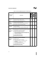
Chapter 3, “Product Options,” which list the number of lock bits implemented for each 8-bit microcontroller.
Table 4-1. Lock Bit Functions
Security
Level
LB3†
LB2†
LB1†
1
U
U
U
No security features implemented. Unless you provide an
encryption file, the factory leaves LB1 unprogrammed. The EA#
pin is sampled and latched on reset, and further programming of
the EPROM or OTPROM is disabled.
2
U
U
P
External code cannot fetch code bytes from on-chip code memory
(MOVC disabled). If you provide an encryption file, the factory
programs LB1.
3
U
P
P
Level 2 plus on-chip code memory verification is disabled. Not
available for factory-programmed microcontrollers.
4
P
P
P
Level 3 plus execution from external memory is disabled. Not
available for factory-programmed microcontrollers.
†
Description
U = unprogrammed; P = programmed. Other combinations of the lock bits are undefined.
Programming LB2 or LB3 makes factory testing impossible. Therefore, the factory programs
only LB1.
4.1.2
Encryption Array
An encryption array allows you to protect your code from unauthorized program verification.
• Unless you provide an encryption file, program verification reads the code memory and
places its contents onto the data bus in its true form.
4-2
CODE SECURITY FEATURES
• If you provide an encryption file, program verification exclusive-NORs (XNORs) each byte
of code with the corresponding byte of the encryption array, then places the encrypted
contents onto the data bus.
Table 4-2 lists each possible combination and result of the exclusive-NOR operation. You must
know the contents of the encryption file in order to decipher the information on the data bus.
Table 4-2. Encryption Truth Table
4.1.2.1
Code Bit
Encryption Bit
Output
0
0
1
0
1
0
1
0
0
1
1
1
Creating an Encryption Array
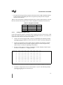
Of the microcontrollers that have encryption arrays, earlier devices have 64-byte arrays, while
newer ones, such as 8XC251Sx, have 128-byte arrays. Regardless of the size, you create an encryption file in the same way. The steps are as follows:
1.
Create a new text file using the editor you use for programming. The following example
command invokes the MSDOS text editor and creates an MCS51 assembly language file.
c:\> edit key.a51
2.
Type the encryption data you have defined. Keep in mind that you should use “random”
values other than FFH, and you should completely fill the size of the encryption array
(either 64 bytes or 128 bytes, depending on the product).
3.
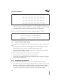
Save the text file. Figure 4-1 shows a saved MCS51 assembly language example. Figure
4-2 shows a saved MCS51 ‘C’ language example.
keyrom: db
000h, 011h, 022h, 033h, 044h, 055h, 066h, 077h
db
088h, 099h, 0aah, 0bbh, 0cch, 0ddh, 0eeh, 0ffh
db
000h, 011h, 022h, 033h, 044h, 055h, 066h, 077h
db
088h, 099h, 0aah, 0bbh, 0cch, 0ddh, 0eeh, 0ffh
db
000h, 011h, 022h, 033h, 044h, 055h, 066h, 077h
db
088h, 099h, 0aah, 0bbh, 0cch, 0ddh, 0eeh, 0ffh
db
000h, 011h, 022h, 033h, 044h, 055h, 066h, 077h
db
088h, 099h, 0aah, 0bbh, 0cch, 0ddh, 0eeh, 0ffh
db
000h, 011h, 022h, 033h, 044h, 055h, 066h, 077h
end
Figure 4-1. Sample Assembly Code (key.a51) for a 64-byte Encryption Array
4.
Assemble or compile the text file to create an object (.obj) file. The following example
command assembles the file created in step 3.
c:\> asm51 key.a51
4-3
ZAPCODE II HANDBOOK
code char keyrom[] =
{0x00, 0x11, 0x22, 0x33, 0x44, 0x55, 0x66, 0x77
0x88, 0x99, 0xaa, 0xbb, 0xcc, 0xdd, 0xee, 0xff
0x00, 0x11, 0x22, 0x33, 0x44, 0x55, 0x66, 0x77
0x88, 0x99, 0xaa, 0xbb, 0xcc, 0xdd, 0xee, 0xff
0x00, 0x11, 0x22, 0x33, 0x44, 0x55, 0x66, 0x77
0x88, 0x99, 0xaa, 0xbb, 0xcc, 0xdd, 0xee, 0xff
0x00, 0x11, 0x22, 0x33, 0x44, 0x55, 0x66, 0x77
0x88, 0x99, 0xaa, 0xbb, 0xcc, 0xdd, 0xee, 0xff};
Figure 4-2. Sample ‘C’ Code (key.c) for a 64-byte Encryption Array
5.
Convert the object ( .obj) file to an Intel hex (.hex) file. Appendix B describes the format
of Intel hex files. The following example command creates an Intel hex file.
c:\> oh key.obj
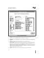
Figure 4-3 shows the hex file that results from the examples in Figures 4-1 and 4-2.
:1000000000112233445566778899AABBCCDDEEFFF8
:1000100000112233445566778899AABBCCDDEEFFE8
:1000200000112233445566778899AABBCCDDEEFFD8
:1000300000112233445566778899AABBCCDDEEFFC8
:00000001FF
Figure 4-3. Sample Intel Hex Format File (key.hex) for a 64-byte Encryption Array
4.1.3
Lock Bits and Encryption Array
The combination of an encryption array and a lock bit protects your code in the following two
ways:
• The encryption array renders the result of program verification meaningless to anyone
without knowledge of the sequence and contents of the encryption array.
• The lock bit prevents a MOVC instruction executing in external memory from fetching
code from internal nonvolatile memory.
For microcontrollers that have both an encryption array and a lock bit:
• If you wish to use either security measure, you must use both.
• If you provide an encryption file, the factory programs the lock bit; otherwise, the factory
leaves the lock bit unprogrammed.
4.1.4
Programming Considerations
This section lists several implications to consider when using these protection features.
• Code and the encryption files must begin at 0000H for all 8-bit microcontrollers except the
8XC251Sx. For the 8XC251Sx, code and the encryption files must begin at FF0000H.
Please consult the documentation for your assembler or compiler to determine the directive
to assemble or compile your code and encryption array at the appropriate address.
4-4
CODE SECURITY FEATURES
• The encryption file that you send to Intel must be in Intel hex format, and it must have valid
checksum values.
— Appendix B describes the format of Intel hex files.
— ZapCode II provides checksum values both before and after transmission of your file to
Intel. If the two match, the checksum is valid.
• Any encryption byte containing FFH reveals a code byte during program verification.
— Use “random” values other than FFH for greater code security.
• Any code byte containing FFH reveals an encryption byte during program verification.
— A large block of unprogrammed code bytes (greater than the size of the encryption
array) reveals the entire encryption array.
— Program unused code bytes with “random” values other than FFH (the unprogrammed
value). Otherwise, program verification will reveal all or part of the encryption array.
• A programmed lock bit cannot be erased and it makes dynamic failure analysis impossible.
— If you provide an encryption file, the factory programs the LB1 lock bit.
4-5
ZAPCODE II HANDBOOK
4.2
MEMORY PROTECTION OPTIONS FOR 16-BIT PRODUCTS
MCS 96 microcontrollers provide several features to deter unauthorized access to the internal
nonvolatile memory. This section briefly describes the following features and their implications:
•
•
•
•
security key
CCB lock bits
PCCB lock bits (EPROM and OTPROM only)
UPROM bits (EPROM and OTPROM only)
Refer to Tables 3-5 and 3-6 in Chapter 3, “Product Options,” to determine which of these features
are available on a particular product. Please read “Programming Considerations” on page 4-8 and
consider the implications of implementing these security options.
4.2.1
Security Key
Programming the lock bits prevents unauthorized access to the nonvolatile memory. However,
you need a means for program verification. The security key provides that means. It allows authorized access to the nonvolatile memory for program verification or further programming. The
key, a 128-bit number that you specify, is located in internal memory (at addresses 2020–202FH
for devices with 16-bit addressing, and at FF2020–FF202FH for devices with extended addressing). Once a security key is programmed, you must provide a matching key to gain access to the
nonvolatile memory.
For microcontrollers with ROM, the key allows program verification after the lock bits are programmed. For microcontrollers with EPROM or OTPROM, the key allows program verification
and further programming. Consult the user’s manual for your specific microcontroller to determine how to program the security key.
4.2.2
CCB and PCCB Lock Bits
Read protection is available for most MCS 96 microcontrollers with internal nonvolatile memory
(ROM, EPROM, or OTPROM). Write protection is available for those with programmable nonvolatile memory (EPROM and OTPROM). This protection is controlled by two lock bits in the
chip configuration register (CCR). The CCR is located at address 2018H for devices with 16-bit
addressing, and at FF2018H for devices with extended addressing. Please consult the user’s manual for your specific microcontroller to determine the locations of the chip configuration byte
(CCB) and the programming chip configuration byte (PCCB), and the methods for programming
them.
For ROM devices, the reset sequence loads the CCR from the CCB for normal operation and for
program verification.
For EPROM and OTPROM devices, the reset sequence loads the CCR from the CCB for normal
operation and from the PCCB when entering programming modes. The CCB lock bits protect the
internal nonvolatile memory during normal operation. The PCCB lock bits add another level of
protection for EPROM and OTPROM devices entering programming modes.
4-6
CODE SECURITY FEATURES
4.2.2.1
CCB Lock Bits
During normal operation, the CCB lock bits control read and write accesses to internal nonvolatile memory. Table 4-3 describes the options. (The programmed state is 0; the unprogrammed
state is 1.)
Table 4-3. Memory Protection for Normal Operating Mode
Read Protect
LOC1 (CCR.7)
Write Protect
LOC0 (CCR.6) †
1
1
No protection. Run-time programming is permitted, and the entire
array of nonvolatile memory can be read.
1
0
Write protection only. Run-time programming is disabled, but the
entire array of nonvolatile memory can be read.
0
1
Read protection. Run-time programming is disabled. If program
execution is external, only the interrupt vectors and CCBs can be
read. For EPROM and OTPROM microcontrollers, the security key is
write protected.
0
0
Read and write protection. Run-time programming is disabled. If
program execution is external, only the interrupt vectors and CCBs
can be read.
†
Protection Status
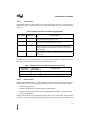
Write protection is applicable to EPROM and OTPROM microcontrollers only.
For ROM devices, the CCB and security key combine to deter unauthorized reading of the internal memory but allow authorized program verification (Table 4-4).
Table 4-4. ROM Protection with Authorized Program Verification
†
4.2.2.2
Read Protect
LOC1 (CCR.7)
Security Key
Programmed?
1
X†
No protection.
0
Yes
ROM-dump permitted with matching security key.
Protection Status
X = Irrelevant (“don’t care”)
PCCB Lock Bits
EPROM and OTPROM devices require additional security to prevent unauthorized programming. For these devices entering programming modes, three levels of protection are available:
• prohibit all programming
• prohibit all programming, but permit authorized ROM dumps
• prohibit serial port programming, but permit authorized ROM dumps, auto programming,
and slave programming
These protection levels are provided by the PCCB lock bits, the CCB lock bits, and the internal
security key (Table 4-4). When entering programming modes, the reset sequence loads the PCCB
4-7
ZAPCODE II HANDBOOK
into the chip configuration registers. It also loads the CCB into internal RAM to provide an additional level of security.
Table 4-5. Memory Protection Options for EPROM and OTPROM Programming Modes
LOC1
(CCR.7)
PCCB
†
LOC0
(CCR.6)
CCB
Security Key
Programmed
?
Protection Status
CCB
PCCB
1
1
1
1
No
No protection. All programming modes allowed.
1
X
0
X
Yes
All programming disabled. ROM-dump permitted with
matching security key.
X
X
X
X
Yes
Serial programming disabled.
1
0
1
0
Yes
Serial programming disabled. Auto and slave
programming permitted with matching security key.
0
X
0
X
X†
All programming unconditionally disabled.
X = Irrelevant (“don’t care”)
4.2.3
UPROM Bits
EPROM and OTPROM microcontrollers have additional protection provided by two unerasable
PROM (UPROM) bits. The DEI bit prevents external instruction fetches, and the DED bit prevents external data fetches. If both bits are programmed, an attempt to fetch data or instructions
from external memory causes a device reset. Setting DED disables ROM-dump (program verification) mode.
4.2.4
Oscillator Failure Detection
Some microcontrollers have circuitry than can detect an oscillator failure (frequency below approximately 100 kHz) and cause a device reset. This circuitry is enabled by the OFD bit. For
EPROM and OTPROM microcontrollers, please consult the user’s manual for the procedure to
program this bit. For ROM devices, if you equate location 2016H to the value 0CDEH, Intel manufacturing will program the OFD bit.
4.2.5
Programming Considerations
This section describes implications to consider when using these protection features.
• Enable the CCB lock bits only if you are submitting your ROM code electronically, using
ZapCode II.
• If you enable the CCB or PCCB lock bits, you must also program a security key. Otherwise,
you have no means to access the internal memory for program verification.
• UPROM bits can be programmed, but cannot be erased. For this reason, Intel
manufacturing does not enable these features. If you wish to use the DED and DEI features,
you must enable them using the procedure described in the user’s manual for your
microcontroller.
4-8
CODE SECURITY FEATURES
• Programming the DED or DEI bit makes dynamic failure analysis impossible. If a
microcontroller’s DED or DEI bit is programmed, you cannot return the device to Intel for
failure analysis.
• If you program the UPROM bit that disables external data fetches (DED), you cannot enter
ROM-dump mode for program verification.
• For ROM devices that have oscillator failure detection (OFD) circuitry, equate location
2016H to the value 0CDEH if you want Intel to enable the OFD feature.
4-9
5
Specify the Part
Marking
CHAPTER 5
SPECIFY THE PART MARKING
This chapter defines Intel’s marking guidelines for the device you are ordering. You can select
either Intel’s standard embedded-microcontroller ROM-device part marking or choose to customize your part’s marking. You must have this information available to fill in the ZapCode II
menus.
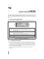
5.1
INTEL STANDARD PART MARKING
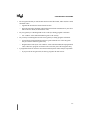
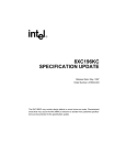
Figure 5-1 shows Intel’s standard part marking format for embedded microcontroller devices.
Product-name 1234
FPO# L2123456
Intel (m)(c) 1983 (copyright)
Line 1:
(Line 1)
(Line 2)
(Line 3)
(Line 4)
Product-name 1234
Where: Product-name is the complete product name (see Figure 3-1 on page 3-2)
1234 = ROM code ID number (see “Record the ROM Number” on page 8-17 for the
source of this number)
Line 2:
FPO# L2123456
Where: FPO# = Factory Process Order Number
L2123456 is Intel's internal lot tracking number. It includes the factory ID, the test
manufacturing date code, and the FAB process order number.
Line 3:
Line 3 is a blank line in this example.
Line 4:
Contains Intel copyright information. All product markings must include the copyright
and logo.
Figure 5-1. Intel Standard Part Mark Example
5.2
CUSTOMIZED PART MARKING
If you choose to customize the marking for your device, use the guidelines in this section.
• Lines 1, 2, and 3 can all be used for your customized marking, with each line containing up
to 22 characters. The maximum number of characters allowed on each of the three lines
depends on the package, device, and number of leads (“Determining Maximum Characters
Per Line” on page 5-2 provides details).
• Line 4 contains Intel copyright information and is required. This line may not be
customized.
5-1
ZAPCODE II HANDBOOK
5.2.1
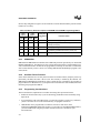
Determining Maximum Characters Per Line
To determine how many characters per line you may use for customized part marking, follow
these steps:
1.
Refer to the appropriate table in Chapter 3 to find the product you have already chosen.
For example, if you are using a commercial 16-bit microcontroller, refer to Table 3-5 on
page 3-10.
2.
Find your device under the “Device” column. Example: 83C196NU
3.
Select a package type from the “Package Options” column. For example, the package
options for the 83C196NU are the 100-lead QFP (S100) or SQFP (SB100).
4.
Find the package in Table 5-1 and read the “Characters Per Line” column. This is the
maximum number of characters that you may use for any customized part marking line for
that package type. Example: For package option “S” with 80 or 100 pins, the maximum
number of characters per line is 15.
Table 5-1. Part Marking Limits
Package Description
5-2
Package Designator
Characters Per Line
40L P-DIP
P
18
48L P-DIP
P
22
44L PLCC
N
11
52L PLCC
N
12
68L PLCC
N
12
44L QFP
S
8
80/100L QFP
S
15
64L SDIP
U
18
6
Select a Packing
Method
CHAPTER 6
SELECT A PACKING METHOD
Intel has devised several packing methods to protect your product during shipping. The packingmethod choices are somewhat dependent upon the device package you chose.
A brief description of some packing options are described in the following sections. For additional information on transport media and packing, please refer to the Shipping and Packaging data
sheet (literature order number 240822).
6.1
CARRIERS
Plastic carriers hold each unit. Loaded carriers are placed in tubes.
Carriers are either coated with antistatic surface treatment or are intrinsically static dissipative.
Carriers are available for QFP and SQFP packages.
Flatpack packages are shipped flat to be trimmed and formed at the customer site. They have fragile leads that need a carrier’s additional protection.
6.2
TAPE AND REEL
The tape and reel packing system places surface-mount devices (SMT) in a tape that is embossed
with individual carrier pockets. A cover-tape seal helps retain and protect the devices. The loaded
tapes are wound onto a reel.
Tape and reel packaging is growing in popularity, especially for PLCCs, because it preserves lead
integrity and lends itself to easy automation at board-level usage. TSOPs and PQFPs may also be
available in tape and reel.
The number of devices per reel (or capacity per reel) will vary depending on the lead count of the
devices involved. A product must be ordered in appropriate tape and reel increments.
6.3
TRAY
Shipping trays comply with JEDEC standard dimensions. All JEDEC trays have the same outside
dimensions and are easily stacked for storage and manufacturing.
Trays are constructed of polyethersulfone (PES) or equivalent because of its high deflection temperature, superior strength, and dimensional stability. High-temperature trays can be baked to
125.50 C. Low-temperature trays can withstand a maximum sustained temperature of 60.50 C.
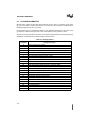
Table 6-1 lists the packages for which trays are available.
6-1
ZAPCODE II HANDBOOK
Table 6-1. Tray Package Options
Package
6.4
Number of Leads
PQFP
84-lead, 100-lead, 132-lead, 164-lead, 196-lead
PGA
68-lead, 88-lead, 132-lead, 168-lead, 208-lead, 240-lead
PLCC
28-lead sq, 28-lead rec, 44-lead sq, 68-lead sq, 84-lead sq
TSOP
32-lead, 40-lead
SOP
32-lead, 44-lead
CQFP
196-lead flat, 164-lead flat
TUBE
Plastic shipping and handling tubes are manufactured from PVC with an antistatic surfactant
treatment. Standard tubes for most package types are translucent and allow visual inspection of
units within the tube. Carbon-impregnated, black conductive tubes are available for all parts
where device or use characteristics require them. Most device package types are available in
tubes.
6.5
WAFFLE PACK
A waffle pack is a plastic container designed to protect sorted die during shipment.
6.6
WAFER BOAT
A wafer boat is a plastic container designed to protect vertically aligned wafers during shipment.
6-2
7
Install or Delete
ZapCode II
CHAPTER 7
INSTALL OR DELETE ZAPCODE II
This chapter contains instructions for installing and deleting ZapCode II. It also contains instructions for using the ZapCode II online training course, for completing or updating the Initial Setup
screen, and for completing or updating the Customer Profile screen.
• If you have already installed ZapCode II, and do not need to update the Initial Setup or
Customer Profile screens, and do not want to delete ZapCode II, skip to the next chapter.
— If you want to update the Initial Setup screen, skip to “Complete or Update the Initial
Setup” on page 7-6.
— If you want to update the Customer Profile screen, skip to “Complete or Update the
Customer Profile and Password” on page 7-9.
• If you have already installed ZapCode II, and want to delete it, skip to “Delete ZapCode II”
on page 7-13.
• If you have received your ZapCode II Starter Kit and are ready to begin installation, skip to
“Installation Requirements” below.
— If you do not have a Starter Kit you can download it from the Internet (see “World
Wide Web” on page 1-4).
7.1
INSTALLATION REQUIREMENTS
To successfully install ZapCode II, you must have the minimum hardware and software requirements listed in “Hardware and Software Requirements” on page 2-1.
You must also have a username and password, both of which are included with the ZapCode II
Starter Kit. If you do not have a username and password, phone Intel at 602 554-8618 and they
will be provided over the phone.
7.2
CHOOSE AN INSTALLATION METHOD
ZapCode II loads drivers that conflict with most network and many hardware device drivers. To
prevent permanent changes to your system configuration files, ZapCode II lets you choose between two alternative boot configuration methods. Each method allows you to switch back and
forth between your usual configuration and the ZapCode II configuration. Whichever method you
choose, your usual configuration is not affected when you access ZapCode II. You can boot or
re-boot to either configuration.
The two methods available for installing ZapCode II are the boot diskette method and the multiple
boot configuration method.
7-1
ZAPCODE II HANDBOOK
7.2.1
Boot Diskette Method
This method loads a ZapCode II directory and certain program files to your system, and then creates a ZapCode II boot diskette. You use the boot diskette in Drive A to boot your system when
you want to start ZapCode II. You remove the diskette from Drive A and re-boot to your normal
configuration after using ZapCode II. Intel recommends this method.
The boot diskette method has the following advantages and disadvantages:
• Advantages:
— safest in terms of preserving your existing system configuration files
— easiest to install
• Disadvantages:
— slower operation than using the multiple boot configuration method
— diskette can be lost and thus unavailable when you need it
7.2.2
Multiple Boot Configuration Method
This method creates a new DOS 6.x multiple-boot configuration menu, or modifies an existing
one. This method is the easiest to use, but is more difficult to install than the boot diskette method.
When booting using this method, your system will display a menu giving you the option of running either ZapCode II or some other configuration, including your normal configuration.
• If you already use a DOS 6.x multiple-boot menu and select this method, the ZapCode II
setup will give you additional options for modifying your existing menu.
• If you do not already use a DOS 6.x multiple-boot menu and you select this method, the
ZapCode II setup will create the multiple-boot menu for you.
The multiple boot configuration method has the following advantages and disadvantages:
• Advantages:
— easier to use than the boot diskette method
— faster operation than the boot diskette method
— always available on-line; no diskettes to lose
• Disadvantages:
— more difficult to install than the boot diskette method
— makes major manipulations of your existing system configuration files
— If you install ZapCode II and then delete it some time later, after making changes to
your autoexec.bat and config.sys files (e.g., adding a CD ROM driver), you will lose
those changes unless you delete ZapCode II manually (rather than using the Delete
ZapCode II icon in the ZapCode II program group).
7-2
INSTALL OR DELETE ZAPCODE II
7.3
INSTALL THE ZAPCODE II SOFTWARE
Perform the following steps to install ZapCode II.
1.
Start the Windows software.
2.
Open the Program Manager.
3.
If you have an external modem, turn it on.
4.
Insert the ZapCode II for Windows HD Disk (Disk 1) into drive A.
5.
From the Program Manager, select Run... in the File menu.
6.
Type a:\setup and press the Enter key. The Initializing Setup message box will display
followed by the ZapCode II Setup box, showing the default installation path.
a. The default installation path is C:\ZapCode. Enter a different path if you wish. Do not
change the name of the directory.
WARNING
The installation path must be to a local drive, such as C:\. Attempting to install
ZapCode II to a network location will disable ZapCode II, requiring you to
begin the installation process again from step 5.
7.
Click on the Continue button in the Setup box. A screen message to start your modem
will appear. Start your modem if you have not already done so.
8.
Click on the Start Test button in the message box. ZapCode II Setup will test your
modem and verify that it is working and on either COM1 or COM2. Setup will alert you if
there are problems and then terminate the installation. The ZapCode II Setup screen will
display after the test is completed.
If Setup terminates, phone the number which displays on the screen for assistance.
9.
Click on the OK button in the message box that identifies your Com port. A setup
message will display asking for your workstation name.
10. Enter a workstation name composed of six alphanumeric characters (letters and/or
numbers only). Both upper and lower case will work.
11. Click on the Continue button in the Setup box. A screen message regarding ZapCode II’s
configuration requirements will appear.
12. Click on the OK button in the message box. The Boot Options screen will appear.
13. For DOS 5.x users:
a. Select the boot diskette method (it is the only choice available).
b. Click on the Continue button. A message box will display advising you to have a blank
diskette ready.
c. Skip to step 16.
7-3
ZAPCODE II HANDBOOK
14. For DOS 6.x users:
a. Select your boot method of choice.
b. Click on the Continue button.
15. If you chose the multiple boot configuration method, skip to step 17.
16. If you chose the boot diskette method:
a. Click on the OK button in the Setup message box. The ZapCode II program files on
disk 1 will be copied to your hard drive.
b. Insert installation disk 2 when prompted and click on the OK button. Installation will
complete and display a message that AUTOEXEC.ZC2 has been created, leaving your
original AUTOEXEC.BAT file unchanged.
c. Click on the OK button in the message box. A message will display that CONFIG.ZC2
has been created, leaving your original CONFIG.SYS file unchanged.
d. Click on the OK button in the message box. A message will display that WIN.ZC2 has
been created, leaving your original WIN.INI file unchanged.
e. Click on the OK button in the message box. A message will display that SYSTEM.ZC2
has been created, leaving your original SYSTEM.INI file unchanged.
f. Click on the OK button. A message to insert a diskette in drive A will appear.
g. Insert a formatted disk (labeled ZapCode II Startup) in drive A when prompted.
WARNING
The disk inserted in drive A must not be write protected. A write protected
disk will abort the setup and require you to start the installation process again
from step 5.
h. Wait while ZapCode II startup files are copied to the startup disk in Drive A. A screen
message saying this phase of the installation is complete will display when completed.
i. Click on the OK button in the message box.
j. Exit Windows software.
k. Reboot your computer with the ZapCode II Startup disk in drive A. Your computer will
boot in the ZapCode II configuration.
l. Skip to “The ZapCode II Program Group” on page 7-5.
17. Wait while the ZapCode II program files are copied to your hard drive. The ZapCode II
Setup box will display the copy status and prompt you to change diskettes to complete the
installation process. If you receive an error message during this process, write down the
indicated problem and call the number which displays on the screen.
18. If you do not already have a multiple configuration menu on your computer:
a. Wait until ZapCode II displays a message advising you that AUTOEXEC.ZC2,
CONFIG.ZC2, and WIN.ZC2 files have been created, leaving your original
AUTOEXEC.BAT, CONFIG.SYS, and WIN.INI files unchanged.
b. Skip to step 20.
7-4
INSTALL OR DELETE ZAPCODE II
19. If you do already have a multiple configuration menu:
a. Wait until ZapCode II displays a message telling you that WIN.ZC2 was successfully
installed, leaving your original WIN.INI file unchanged.
b. Click on the OK button. Another message will display telling you that SYSTEM.ZC2
was successfully installed, leaving your original SYSTEM.INI file unchanged.
c. Click on the OK button. The Modification Options screen will display. It offers four
configuration options. Option 1 (Insert ZapCode II item into Main Menu) is the default
and is the option recommended by Intel. Options two, three, and four are provided only
for advanced users. If you wish to select options two, three, or four, and have questions
regarding their functionality, please phone Intel at (602) 554-8618 for assistance.
d. Select your option of choice and click on the Continue button.
e. If you selected option two, three, or four, proceed according to instructions displayed
on the screen and/or received by phone from Intel, then skip to step 22.
f. If you selected option 1, a message box will display telling you that AUTOEXEC.BAT
and CONFIG.SYS updates are complete, and that their backup files are
AUTOEXEC.ZAP and CONFIG.ZAP.
20. Click the OK button in the message box. A new message will display telling you that
installation is complete.
21. Click the OK button in the message box.
22. Exit Windows.
23. Reboot your computer, selecting ZapCode II in the multiple boot configuration menu.
7.3.1
The ZapCode II Program Group
The ZapCode II installation creates a ZapCode II program group with two icons:
• The ZapCode II icon, which is used to open the ZapCode II interface and display the
welcoming screen.
• The Delete ZapCode II icon, which is used to delete the ZapCode II software from your
computer.
7.4
HOW TO USE THE ONLINE TRAINING COURSE
If this is the first time you have used the ZapCode II software, you may want to use the Online
Training Course to preview the ZapCode II software screens and learn how to interact with the
software.
If you do not wish to use the Online Training Course:
1.
Click on the Exit button in the welcoming screen.
2.
Skip to “Complete or Update the Initial Setup” on page 7-6.
To use the Online Training Course, perform the following steps.
1.
Click on the Online Training Course button.
7-5
ZAPCODE II HANDBOOK
2.
Perform the instructions provided by the on-screen prompts. Exercises and help windows
provide you with experience completing all screens (both required and optional) that you
will need for using ZapCode II to transmit your ROM code to Intel.
3.
Click on the Close button when you have completed the online training course.
4.
Click on the OK button to return to the welcoming screen.
7.5
COMPLETE OR UPDATE THE INITIAL SETUP
If you have already completed the Initial Setup, and do not need to change any of the Initial Setup
entries, skip to “Complete or Update the Customer Profile and Password” on page 7-9.
If you have not already completed and saved the initial ZapCode II setup, perform each of the
following steps in the order given. Your entry or a system default entry must appear in each response box in the Initial Setup before the ZapCode II interface on your computer will connect you
to the ZapCode II system at Intel. After all of your responses have been entered and saved, Initial
Setup is completed. You complete the entire Initial Setup only the first time you use ZapCode II.
If you want to make a change to any response that has been previously entered and saved, perform
step 2, update the appropriate response(s), and then skip to step 9.
1.
7-6
Launch ZapCode II by double-clicking on the ZapCode II icon in the ZapCode program
group. The ZapCode II welcoming screen will open (Figure 7-1).
INSTALL OR DELETE ZAPCODE II
Figure 7-1. The ZapCode II Welcoming Screen
2.
Click on the Initial Setup button. The Initial Setup screen (Figure 7-2) will display.
7-7
ZAPCODE II HANDBOOK
Figure 7-2. Initial Setup Screen
3.
Com Port: Click on COM1 or COM2, whichever port the installer identified for your
system in step 8 of “Install the ZapCode II Software” on page 7-3.
4.
Baud Rate: Click on the baud rate for your modem. The maximum speed supported is
19,200.
5.
Phone Line Type: Click on the phone line type your modem will use.
6.
Phone Number: Select the phone number for the location to which you will send your
ROM code. This number must be selected before entering the prefix number in step 7.
7.
Type In Any Prefix Numbers For An Outside Line: Enter the prefix (if any) that your
modem will have to dial to get an outside line (example: 9,). This entry must be made
after selecting the phone number in step 6.
8.
Modem: Click on the name of your modem type or leave it set to Default.
7-8
INSTALL OR DELETE ZAPCODE II
9.
Click on the OK button to save your changes. A screen prompt will appear telling you that
your settings are saved and that you need to input your username and password.
10. Click the OK button in the prompt box to return to the welcoming screen.
7.6
COMPLETE OR UPDATE THE CUSTOMER PROFILE AND PASSWORD
If you have already completed the Customer Profile, and do not need to change any of its entries
or your password, skip to “How To Download the ZapCode II Handbook” on page 7-12.
7.6.1
Connect to Intel
Perform the following steps to connect your modem to Intel.
1.
Enter your username and your current password in the spaces provided on the welcoming
screen.
2.
Click on the OK button. Your modem will activate and connect you to the Intel-resident
ZapCode II system.
3.
Wait while the ZapCode II system automatically compares the ZapCode II files on your
hard drive to the Intel-resident ZapCode II system files.
• A “Working...No User Input Needed” message will appear during this comparison.
This check will determine whether or not you have the most current ZapCode II
software loaded on your system. If you do not, ZapCode II will automatically
download the most current files to your system, replacing the old files.
• Screen messages will display to name any files that are being replaced.
• Following authentication, the Main Menu (Figure 7-3) will display on your screen.
7-9
ZAPCODE II HANDBOOK
Figure 7-3. The ZapCode II Main Menu
7.6.2
Complete the Customer Profile
If you have already completed the Customer Profile and want to change only your password, skip
to Section 7.6.3.
Perform each of the following steps in the order given. You must complete all required entries
in each Customer Profile field before you can advance to the next screen. After all of the required
responses for each field have been entered and saved, the Customer Profile is completed. Optional questions may or may not be answered, at your discretion. You must complete the Customer
Profile only the first time you use ZapCode II.
If you want to make a change to any Customer Profile response that has been previously entered
and saved, perform step 1, update the appropriate response(s), and then skip to step 4.
1.
7-10
Click on the Customer Profile button. The ZapCode II Customer Profile screen is
displayed (Figure 7-4).
INSTALL OR DELETE ZAPCODE II
Figure 7-4. Example of a Completed Customer Profile Screen
2.
Complete the Company Information block. This is required information.
a. Company Name: Enter the name of your company. Do not use apostrophes in the
name.
b. Key Contact: Enter your name or the name of the person Intel should contact for any
issues on your new code.
c. Phone Number: Enter the phone number of the key contact. It is helpful to enter the
area code for U.S. customers and country and city code for international customers.
d. Address: Enter the street address of your company.
e. City: Enter the city where your company is located.
f. State: Enter the state where your company is located.
g. Zip Code: Enter the zip code where your company is located.
7-11
ZAPCODE II HANDBOOK
h. Distributor/Branch: Enter your distributor or branch name. If this field is not
applicable to you, enter “NA.”
3.
Complete the Optional Information block (if desired).
a. Alternate Contact: Enter the name of the person Intel should contact for any issues on
your new code when the key contact is not available.
b. Phone Number: Enter the phone number of the alternate contact. It is helpful to enter
the area code for U.S. customers and country and city code for international customers.
c. Fax Number: Enter the fax number for either the key contact or the alternate contact. It
is helpful to enter the area code for U.S. customers and country and city code for
international customers.
d. Intel Sales Office: Enter the name of your Intel sales office (if applicable).
e. End Customer: Enter the end customer name. This is generally defined as the
company that is receiving the finished product, and is usually the same as the company
name you entered in step 2a. ZapCode II autofills this information for you when you
complete step 2a.
4.
Click on the OK button.
5.
Wait while the system displays a “Working” screen message and saves your entries. The
Main Menu will display on the screen when the save is completed.
7.6.3
Change Your Password
If you do not want to change your password, skip to “How To Download the ZapCode II Handbook” on page 7-12.
Perform the following steps to change your password.
1.
Select Change Password on the Options menu. A box for entering your new password
will display on your screen.
2.
Enter your new password in the box. There is a 15-character limit.
3.
Click on the OK button. A screen message displays confirming your new password and
advising you to make a record of it.
4.
Click on the message box OK button. The Main Menu returns.
7.7
HOW TO DOWNLOAD THE ZAPCODE II HANDBOOK
If you do not want to download the most current copy of this handbook, skip to “Delete ZapCode
II” on page 7-13.
If you do want to download the most current copy of this handbook, perform the following steps
to transfer the most current electronic copy of this handbook to your computer.
1.
Click on the Download ROM Handbook button on the Main Menu. A screen message
asking you if you want the documentation downloaded will display on your screen.
2.
Click on the Yes button in the message box and follow instructions in the dialog box.
7-12
INSTALL OR DELETE ZAPCODE II
3.
Click on the OK button.
4.
Wait while ZapCode II downloads/updates your documentation.
7.8
DELETE ZAPCODE II
If you do not wish to delete ZapCode II from your computer, skip to Chapter 8.
If you wish to delete ZapCode II from your computer, use one of two methods:
• Automated — use the Delete ZapCode II icon in the ZapCode II program group. This icon
is used to delete the ZapCode II software from your computer. Using this icon does not
delete any ZapCode II subdirectories. Your ROM code data files are not affected by any
deletion.
• Manual — select and delete individual files and icons, and the ZapCode II directories.
7.8.1
Automated Method
CAUTION
If you use the multiple boot configuration method, and have made changes to
the c:\autoexec.bat and the c:\config.sys files that you do not want to lose, use
the manual method (see “Manual Method” on page 7-14).
Perform the following instructions to remove ZapCode II from your hard drive using the automated method.
1.
Start Windows.
2.
Double-click on the Delete ZapCode II icon in the ZapCode II program group. A
message welcoming you to the ZapCode Deinstall setup will display.
3.
Click on the OK button in the welcoming message box. A verification message will
display asking you to confirm that you want to delete ZapCode II from your computer.
4.
Click on the Yes button in the verification message box.
• ZapCode II program files will automatically be deleted from the ZapCode directory on
your hard drive.
• The c:\autoexec.bat and the c:\config.sys files saved when ZapCode II was installed
will be restored.
• The Deinstall message box will appear telling you that ZapCode program files have
been deleted from your computer.
5.
Click on the OK button in the Deinstall message box. The screen display will return to the
ZapCode II program group.
6.
Delete the Delete ZapCode II icon in the ZapCode II program group.
7.
Delete the ZapCode II icon in the ZapCode II program group.
8.
Delete the ZapCode II program group.
7-13
ZAPCODE II HANDBOOK
9.
Go to the drive where you installed ZapCode II.
10. Delete the ZCdelete directory and its contents.
11. Open the ZapCode directory.
12. If there are any transmission subdirectories in the ZapCode directory:
a. Review the transmission subdirectories.
b. Delete the subdirectories you do not want to save.
13. If there are no transmission subdirectories remaining in the ZapCode directory (the
ZapCode directory is now empty), delete the ZapCode directory.
14. If there are transmission subdirectories remaining in the ZapCode directory, you have the
following choices:
a. Leave the ZapCode directory as is. ZapCode II will put its program files into the
directory the next time you install ZapCode II.
b. Rename the directory. ZapCode II will create a new ZapCode directory the next time
you install it.
ZapCode II has now been deleted from your computer.
7.8.2
Manual Method
If you choose the manual method, you select and delete files, icons, directories, and the ZapCode
II program group just as you would any other file, icon, directory, or program group. All changes
you have made to your c:\autoexec.bat and c:\config.sys files since installing ZapCode II will be
preserved.
Perform the following instructions to remove ZapCode II from your hard drive using the manual
method.
1.
Start the Windows software.
2.
Go to the drive where you installed ZapCode II.
3.
Delete the ZCdelete directory and its contents.
4.
Open the ZapCode directory.
5.
Select and delete all ZapCode II program files in the ZapCode directory.
6.
If there are any transmission subdirectories in the ZapCode directory:
a. Review the transmission subdirectories.
b. Delete the subdirectories you do not want to save.
7.
If there are no transmission subdirectories remaining in the ZapCode directory (the
ZapCode directory is now empty), delete the ZapCode directory.
8.
If there are transmission subdirectories remaining in the ZapCode directory, you have the
following choices:
7-14
INSTALL OR DELETE ZAPCODE II
a. Leave the ZapCode directory as is. ZapCode II will put its program files into the
directory the next time you install ZapCode II.
b. Rename the directory. ZapCode II will create a new ZapCode directory the next time
you install it.
9.
Go to the Program Manager.
10. Delete the Delete ZapCode II icon in the ZapCode II program group.
11. Delete the ZapCode II icon in the ZapCode II program group.
12. Delete the ZapCode II program group.
13. Go to the File Manager.
14. Select By File Type... in the View menu.
15. Click on Show Hidden/System Files to select it.
16. Click on the OK button.
17. Go to the root directory (e.g., C:\).
18. Locate and delete the file named ZCCURDIR.TXT.
19. Select By File Type... in the View menu.
20. Click on Show Hidden/System Files to unselect it.
21. Click on the OK button.
22. If you use the multiple boot configuration method:
a. Edit the c:\autoexec.bat and c:\config.sys files to remove all ZapCode II configuration
statements. If you need any assistance identifying these statements phone Intel at 602
554-8618.
b. Go to the File Manager and delete the following files:
•
•
•
•
c:\Windows\Win.ZC2
c:\Windows\System.ZC2
c:\autoexec.zap
c:\config.zap
ZapCode II has now been deleted from your computer.
7-15
8
Transmit and Verify
the ROM Code
CHAPTER 8
TRANSMIT AND VERIFY THE ROM CODE
This chapter contains instructions for performing the following activities:
•
•
•
•
Starting ZapCode II
Creating an initial checksum (optional)
Identifying the product you are ordering and its features
Transmitting the ROM code, encryption file (if applicable), and configuration file (if
applicable) to Intel
• Editing files returned to your computer from Intel following transmission
8.1
START ZAPCODE II
Start ZapCode II using one of the following two methods.
8.1.1
Boot Disk Method
1.
If your system is already running in some configuration other than ZapCode II, exit to the
DOS prompt.
2.
Insert your ZapCode II startup disk in drive A.
3.
Boot or reboot your computer. It will start up in ZapCode II and display the welcoming
screen (Figure 7-1 on page 7-7).
4.
Skip to “Create A Checksum Optional)” on page 8-2.
8.1.2
Multiple Configuration Menu Method
1.
If your computer system is already running in some configuration other than ZapCode II,
exit to the DOS prompt.
2.
Boot or re-boot your computer.
3.
Select either the ZapCode II configuration or some other configuration.
• If ZapCode II created a multiple configuration menu when you loaded it (you did not
have a multiple configuration menu before loading ZapCode II), your initial screen will
display a counter counting down from 15 seconds. If you do not select ZapCode II
within 15 seconds and press the Return key, your computer will automatically boot up
in the Normal configuration and display the welcoming screen (Figure 7-1 on page
7-7).
• If ZapCode II added itself to an existing multiple configuration menu (you had a
multiple configuration menu before loading ZapCode II), select Load ZapCode II
8-1
ZAPCODE II HANDBOOK
either by using the down arrow key and then pressing the Return key, or by typing the
ZapCode II option number and pressing the Return key. Your computer will boot in the
ZapCode II configuration and display welcoming screen (Figure 7-1 on page 7-7).
8.2
CREATE A CHECKSUM OPTIONAL)
Before transmitting your ROM code file to Intel, the ZapCode II welcoming screen gives you the
option of converting it to hex and creating a pre-transmittal checksum. This option to produce a
translated, filled hex file is provided so that you may compare the hex file to your ROM code, or
so that you may load it into your device (tester). You may also use the checksum for comparison
with your device’s checksum (for example, from a data I/O).
If you do not choose to create the optional checksum, skip to “Connect to Intel” on page 8-5.
Perform the following steps to create your pre-transmittal checksum.
1.
8-2
Click on the Translate Hex File button on the welcoming screen. The Product
Information for Translation screen will display (Figure 8-1). When first opened, this
screen does not display the “Enable Security Bit” field. This field appears only after you
select a product for which security features are offered. Figure 8-2 illustrates the “Enable
Security Bit” field when a product offering security features is selected.
TRANSMIT AND VERIFY THE ROM CODE
Figure 8-1. Product Information for Translation Screen - Without Security Feature
8-3
ZAPCODE II HANDBOOK
Figure 8-2. Product Information for Translation Screen - With Security Feature
2.
Enter the Product Information data.
a. Product: Select a product in the scroll list by clicking on it.
b. Fill Value: Select a fill value, either FF or 00. This selection tells Intel how you want
the undefined or blank sections of the ROM array filled.
c. Enable Security Bit: Not all Intel products offer security features. If you selected a
product that offers security features, an Enable Security Bit box will be added to the
screen (Figure 8-2). Click on this box if you want security features enabled for your
product option.
d. Address Range: This field is automatically filled when a product is selected. There is
no user input to this field.
3.
Enter the Hex File Location information.
a. Drive: Select the drive where your hex file is located
8-4
TRANSMIT AND VERIFY THE ROM CODE
b. Directories: Select the directory where your hex file is located
c. File Name: Select the hex file by clicking on its name. The name of the file and its path
will appear in red above the File Name scroll box.
4.
Click on the Translate button. ZapCode II will save the translated file to the ZapCode
directory on your hard drive. A message will be displayed showing the path to this
directory. A “Z” suffix is appended to the file name, followed by a number representing
the number of times the file has been translated. Figure 8-3 shows an example of this
message (the file has been translated four times).
Figure 8-3. Example of a Path Message
5.
Click on the OK button in the message box. The file will be translated and a checksum
message will be displayed on the screen (Figure 8-4).
Figure 8-4. Example of a Checksum Message
6.
Click on the OK button in the message box. The Product Information for Translation
screen will return.
7.
Click on the Main Login button. The display will return to the ZapCode II welcoming
screen.
8.3
1.
CONNECT TO INTEL
Enter your username and your password in the spaces provided on the welcoming Screen.
8-5
ZAPCODE II HANDBOOK
2.
Click on the OK button. Your modem will activate and connect you to the Intel-resident
ZapCode II system. Following authentication, the Main Menu (Figure 8-5) will display on
your screen.
Figure 8-5. The ZapCode II Main Menu
3.
8.4
Wait while the ZapCode II system automatically compares the ZapCode II files on your
hard drive to the Intel-resident ZapCode II system files. A “Working...No User Input
Needed” message will appear during this comparison. This check will determine whether
or not you have the most current ZapCode II software loaded on your system. If you do
not, ZapCode II will automatically download the most current files to your system,
replacing the old files. A message box will display identifying the name of each file as it is
updated.
SELECT A PRODUCT AND PRODUCT FEATURES
The Product Selection menu is used to describe your order to Intel. This includes providing information to identify the following items:
8-6
TRANSMIT AND VERIFY THE ROM CODE
•
•
•
•
•
•
•
•
an embedded microcontroller product
a part-marking option
a package type
a packing option
temperature/burn-in choice
special stepping instructions (if applicable)
security features (if applicable)
MHz if the product offers a choice of speeds
These choices give Intel the necessary information to manufacture your product.
Complete the following steps to select your product and the features you have chosen. Each
screen you enter has prompts and field-sensitive help to guide you through the process steps. Each
screen also has a Help button that accesses general information about the screen function.
1.
Click on the Product Selection button in the Main menu. The Product Information screen
will be displayed (Figure 8-6).
8-7
ZAPCODE II HANDBOOK
Figure 8-6. Example of a Product Information Screen
2.
Product: Click on the product that you chose in Chapter 3. Use the vertical scroll bar to go
up and down through the list.
3.
Package Type: This field is populated when you select a product. Click on the package
type that you chose in Chapter 3. Use the vertical scroll bar to go up and down through the
list.
4.
Speed: This box will appear only if the device selected offers different MHz versions.
5.
Pack Option: The packing field is automatically filled in when a product is selected.
Click on the packing method you chose in Chapter 8. Use the vertical scroll bar to go up
and down through the list.
6.
Temp/BI Selection: The available temperature and burn-in option box is automatically
filled in when you select a product. Click on a temperature and burn-in option to select it.
Use the vertical scroll bar to go up and down through the list.
8-8
TRANSMIT AND VERIFY THE ROM CODE
7.
Address Range: The address range is automatically filled in when a product is selected.
There is no user input to this field.
8.
Special Stepping Instruction: A stepping product is either the original design or any
change in the original design of a device which improves its functionality. This
information is required only if you have been notified by Intel that the product is currently
undergoing a production change; otherwise the standard product will be provided.
a. Click on Stepping: Click on the appropriate stepping, if required. Use the vertical
scroll bar to go up and down through the list.
9.
Enable Security: This field will appear only if you select a product that offers security
features. Check this box if you want the security features enabled for your product, if they
are available. Refer to Chapter 4 for security information.
10. Customer Part Markings: Choose either Standard or Custom marking.
a. Standard Marking: This is the default for marking. Click on the Standard Marking?
box and the Custom entry boxes disappear from the screen, and the standard marking
for the device appears in the Standard box. Figure 8-7 shows an example of a selection
for Standard marking with the Custom boxes hidden.
b. Custom (Line 1/Line 2/Line 3): Enter the markings you created in Chapter 5 for each
line. Figure 8-6 shows the entry boxes that appear when Standard Marking? is not
selected.
8-9
ZAPCODE II HANDBOOK
Figure 8-7. Example of a Product Screen With Only Standard Marking Showing
11. Click on the View button. The Current Product Selection screen shows the options you
have selected, including the part marking. Figure 8-8 shows an example.
8-10
TRANSMIT AND VERIFY THE ROM CODE
Figure 8-8. Example of a Part Marking Screen
12. Click on the Return button when you have finished viewing the illustration. The screen
returns to the Product Information window.
13. Click on the OK button. Your settings will be saved and the screen will return to the Main
Menu.
8.5
VERIFY YOUR PRODUCT SELECTION
After completing and closing the Product Selection screen, you can review and verify your part
marking at any time (without entering the Product Selection screen) by clicking on the View
Product Selection button on the Main Menu.
The View Product Selection screen shows the options you have selected, including the part
marking. Figure 8-8 shows an example.
8-11
ZAPCODE II HANDBOOK
Click on the Return button to close the window and return to the Main Menu.
8.6
TRANSMIT THE DATA TO INTEL
After you have verified your selection of product and product features, this information is ready
for transmittal to Intel. Perform the following steps to transmit the data.
1.
Click on the Transmit Data button on the Main menu. The Transmit Data window will
display on your screen. This window is used to locate the files you are transmitting to
Intel.
• These files must be located on your hard drive or on a diskette in drive A.
• The Transmit Data window adjusts itself to provide individual selection boxes for
locating the hex file, the encryption array file, and the configuration file, depending on
the product you selected. For example, Figure 8-9 illustrates a typical Transmit Data
window for a product which requires only a hex file, while Figure 8-10 illustrates a
Transmit Data window for a product requiring a hex file, an encryption array file, and a
configuration file.
• The Display Information box at the top of the Transmit Data window shows your
customer name and the identifies the product you selected.
8-12
TRANSMIT AND VERIFY THE ROM CODE
Figure 8-9. Transmit Data Window Example: Hex File Location Only
8-13
ZAPCODE II HANDBOOK
Figure 8-10. Transmit Data Window Example: Hex, Encryption, Configuration File
Locations
2.
Use the Drives, Directories, and File Name scroll boxes to select the name(s) of the file(s)
to be transmitted to Intel. The selections will appear in red above the applicable selection
boxes.
3.
Complete the entries in the Enter Information area of the window.
a. Comments: Enter any comments you would like Intel to see. There is a 29-character
limit.
b. Fill Value: Select a hex fill value, either FF or 00. This selection tells Intel how you
want the undefined or blank sections of the ROM array filled.
c. Replace Previous Code: If selected, an additional entry field for entering the part
number is displayed in the window. Figure 8-9 illustrates the Transmit Data window
when Replace Previous Code is not selected. Figure 8-11 illustrates the window when it
8-14
TRANSMIT AND VERIFY THE ROM CODE
is selected. Enter the part number for the replacement in this box if Replace Previous
Code is selected.
Figure 8-11. Transmit Data Window With ‘Replace Previous Code’ Selected
4.
Click on the Transmit button. The Intel disclaimer is displayed on your screen.
5.
Read the disclaimer and then click the OK button to continue. A screen message will
appear giving the path to the directory on your hard drive to which files created for this
transmission are copied. Figure 8-12 shows an example of this message.
8-15
ZAPCODE II HANDBOOK
Figure 8-12. Example of a ROM Code Path
6.
Click on the OK button in the ZapCode message box.
7.
Click on the OK button of the Transmit Data window. This invokes the ZapCode II
translation software, which does the following:
•
•
•
•
•
8.7
translates your ROM code into an 8080 Intelec hex format
fills the blank ROM area with your choice of FFH or 00H
transfers your code to Intel’s database
creates the final checksum for the file
assigns a unique ROM code record number to your transmittal
VERIFY THE CHECKSUM
After the transmission is completed, ZapCode II locates the transmitted hex file on your computer
and creates a checksum for it. It then creates a checksum for the same hex file as it was received
at Intel. A comparison of the two checksums follows, with the results displayed in an information
window on your computer.
• If the checksums on your computer and at Intel are the same, ZapCode II will display a
screen message like the example in Figure 8-13.
Figure 8-13. Example of a Successful Checksum Message
8-16
TRANSMIT AND VERIFY THE ROM CODE
• If the checksums on your computer and at Intel do not compare, ZapCode II will display a
message in the following example format: “Hex files did NOT compare. Checksum on hex
file located on your PC = 211DC7E8. Checksum at Intel = FFEEAADD. Please try
transmitting again.”
Click on the OK button to close the ZapCode message window.
If you received the message that the checksums on your computer and at Intel do NOT compare,
repeat sections 8.2 through 8.7.
• If the checksums do NOT compare after retransmitting, contact your distributor or local
sales office for assistance.
8.8
RECORD THE ROM NUMBER
After you have verified the checksum and clicked on the OK button in its message box, ZapCode
II displays an information window that shows the ROM code record number assigned to your hex
file. Figure 8-14 shows an example of a ROM code record number message.
Record the ROM code record number for future use, such as when you place your order with your
distributor or sales office.
Figure 8-14. Example of a ROM Number Message
Click on the OK button to return to the Main Menu.
8.9
EXIT ZAPCODE II
Perform the following instructions to exit ZapCode II and reboot to your normal configuration.
1.
Click on the Close button of the Main Menu.
2.
Click on the OK button to exit ZapCode II. A departing message box will appear.
3.
Click on the OK button in the message box.
4.
If you loaded ZapCode II using the boot diskette method:
a. Remove the boot diskette from drive A.
b. Reboot to return to your normal configuration.
c. Return the boot diskette to storage.
5.
If you loaded ZapCode II using the multiple menu method:
8-17
ZAPCODE II HANDBOOK
a. Exit to the DOS prompt.
b. Perform steps 2 and 3 of “Multiple Configuration Menu Method” on page 8-1 to reboot
to your normal configuration.
8.10 EDIT THE FILES RETURNED FROM INTEL
1.
Go to the ZapCode directory on your hard drive. This directory holds the transmission
files returned to your computer by ZapCode II following your transmittal. The following
files are located in the directory.
• <filename>.hex: Contains the original code file that you transmitted to Intel.
• <ROMcodeNumber>.hex: Contains the new ROM code file after processing by Intel.
The ROM code record number is the number your recorded in Section 8.8.
• cust.txt: Contains the Customer Confirmation letter. This file summarizes the entries
you made in Section 8.4.
• <ROM #> config.hex: Optional depending on the part you selected.
• <ROM #> key.hex: Optional depending on the part you selected.
2.
Open and verify the information in the files named in step 1.
• If there are any errors, contact Intel at the number shown in the cust.txt file.
8-18
9
Place Your Order
CHAPTER 9
PLACE YOUR ORDER
After you transmit your ROM code and verify information in the Customer Confirmation Letter,
ask your local Intel distributor to help you prepare a purchase order for the product you are ordering. The purchase order will include the following minimum information.
• The size (quantity) of your order. There are minimum order size requirements for various
commercial and automotive products. See Table 3-2 on page 3-4.
• The mask and set-up charges for your order. See Table 3-2 on page 3-4.
• A lead-time option. This will determine when your order enters the manufacturing process.
See Table 3-2 on page 3-4.
After receiving this completed purchase order, Intel will schedule your ROM manufacturing.
9-1
A
Product Order Form
APPENDIX A
PRODUCT ORDER FORM
CUSTOMER INFORMATION
Company Name ___________________________________________________________
Contact Name _______________________________ Phone Number: (____) ___________
Address__________________________________ Fax Number: (____) _______________
City ___________________________ State __________ Zip Code __________________
Distributor (if applicable) ____________________________________________________
Sales Office (if applicable)___________________________________________________
PRODUCT
Intel Product Name: ________________________________________________________
Package Type :________
Refer to Table 3-7 on page 3-12 for a
listing of package options.
Operating Temperature† :________
Refer to Table 3-1 on page 3-2 for a listing of
temperature and burn-in options.
†
Default is standard as specified in the Data
Sheet. No character required.
Fill Value ___________ (Fill value for unused address locations can be FF or 00.)
Packing Method ________________ (Refer to Chapter 6, “Select a Packing Method” for a
listing of packing method options.)
A-1
ZAPCODE II HANDBOOK
PART MARKINGS
Commercial QROM devices can use 1 line only for part marking.
Automotive devices can use 3 lines for part marking.
D package (C-DIP)
P package (P-DIP)
N package (PLCC)
S package (QFP)
maximum 10 characters per line (1 line)
maximum 18 characters per line (3 lines)
maximum 11 characters per line (3 lines)
maximum 07 characters per line (1 line)
For Commercial Devices:
1
2
3
4
5
6
7
8
9
10
11
12
13
14
15
16
17
18
6
7
8
9
10
11
12
13
14
15
16
17
18
For Automotive Devices:
1
2
3
4
5
TRANSMITTAL AND SECURITY INFORMATION
Intel’s preferred method of media transportation (in order):
1. ZapCode II (Electronic)
2. Federal Express (Floppy, EPROMs)
Your ROM code method of transportation ______________________________________
(For example: Floppy, 2764A EPROM)
Hex Code Labeled _________________________________________________________
MCS® 51 Security (if applicable):
MCS® 96 Security (if applicable):
Set Security Bit: [ ] YES [ ] NO
Set LOC0 Bit: [ ] YES
[ ] NO
Encryption File Labeled _______________
Set LOC1 Bit: [ ] YES
[ ] NO
SIGNATURE
Customer Signature_______________________ Title:__________________ Date: _______
A-2
B
ROM Code Hex File
Description
APPENDIX B
ROM CODE HEX FILE DESCRIPTION
The ZapCode transmission program takes a ROM-code hex file as input and calculates the checksum. The ROM must be in multiples of 4K and can be any value from 4K to 32K. The transmission program expects a certain format for the hex code.
Each ROM code line must follow this format:
:10001000FE352FCD454BAEFFE43E5D55AAE435EEEF
:
The first character is a colon.
: 10
The next two characters specify in hex the number of bytes in that line. (For this example, the
number of bytes is 10H or 16 decimal.)
:10 0010
The next four characters specify the starting address of the first byte in the line (0010H = 16 decimal).
:100010 00
The next two characters indicate the record type. (The 00 indicates a “normal” record; that is, a
line of hex code that is other than the last line in the file. The record type of the last line in the file
is 01.)
:10001000 FE352FCD454BAEFFE43E5D55AAE435EE
The next several characters are the actual hex bytes of the ROM. (The 16 data bytes of this line
are FE, 35, 2F, CD, 45, 4B, AE, FF, E4, 3E, 5D, 55, AA, E4, 35, and EE.)
:10001000FE352FCD454BAEFFE43E5D55AAE435EE EF
The last two characters are a hex checksum (or parity byte) for the line of code. The checksum
value is a value that, when added to the sum of the record, equals zero. It is the sum that has been
negated.
B-1
Index
INDEX
A
Assembly language, MCS51, 4-3
B
Bulletin board system (BBS), 1-2, 1-3
C
Checksum, 8-2, 8-16, B-1
CompuServe forums, 1-2, 1-4
E
Embedded microcontroller products See
Microcontroller products
Encryption array See Nonvolatile memory options
Encryption file See Nonvolatile memory
F
FaxBack service, 1-2
Fill value, hex file, 8-16
H
Hardware requirements See ZapCode II, hardware
requirements
Hex file
fill value, 8-16
functional description, B-1
Intel format, 4-4, 4-5
I
Installation, ZapCode II See ZapCode, installation
Intel hex file See Hex file
Internet See World Wide Web
L
Lead times See Ordering products
Lock bits see Nonvolatile memory options
M
Mask charges See Ordering products
Memory protection See Nonvolatile memory
options
Memory protection options See Nonvolatile
memory options
Microcontroller products, 16-bit
automotive features
memory characteristics, 3-11
package options, 3-11
security features, 3-11
temperature and burn-in, 3-9
automotive products
CMOS MCS® 96 Microcontrollers —
8XC196EA family, 3-11
CMOS MCS® 96 Microcontrollers —
8XC196KB, KC, KD family,
3-11
CMOS MCS® 96 Microcontrollers —
8XC196Kx, Jx, CA, CB
family, 3-11
commercial features
memory characteristics, 3-10
package options, 3-10
security features, 3-10
temperature and burn-in, 3-9
commercial products
CMOS MCS® 96 Microcontrollers —
8XC196KB, KC, KD family,
3-10
CMOS MCS® 96 Microcontrollers —
8XC196Kx, Jx, CA family,
3-10
CMOS MCS® 96 Microcontrollers —
8XC196MC, MD, MH family,
3-10
CMOS MCS® 96 Microcontrollers —
8XC196Nx family, 3-10
families, 3-9
starting address
ROM code, 3-9
Microcontroller products, 8-bit
automotive features
memory characteristics, 3-8
package options, 3-8
security features, 3-8
temperature and burn-in, 3-5
automotive products
Index-1
ZAPCODE II HANDBOOK
CMOS MCS® 51 — 8XC51Fx family,
3-8
CMOS MCS® 51 — 8XC5x family, 3-8
commercial features
memory characteristics, 3-6–3-7
package options, 3-6–3-7
security features, 3-6–3-7
temperature and burn-in, 3-5
commercial products
CMOS MCS® 251 — 8XC251Sx
family, 3-7
CMOS MCS® 51 — 8XC51Fx,
8XC51GB, 8XC51KB,
8XC51SL, 8XC152 family,
3-6
CMOS MCS® 51— 8XC5x family, 3-6
CMOS UPI, 3-6
low-voltage CMOS MCS® 51 —
8XL5x, 8XL51Fx family, 3-7
families, 3-5
starting address
configuration file, 3-5
encryption array, 3-5
ROM code, 3-5
Minimum order quantity See Ordering products
programming chip configuration byte
(PCCB), 4-6
read protection, 4-6
security key, 4-6, 4-7
UPROM bit, 4-9
UPROM bits, 4-8
write protection, 4-6
8-bit microcontrollers
checksum values, 4-5
code byte, 4-5
development cycle options, 3-3
encryption array, 4-2, 4-3, 4-4
encryption array, assembly language,
MCS51, 4-3
encryption array, assembly language,
MCS51 ’C’ language, 4-3
encryption array, Intel hex file, 4-4
encryption byte, 4-5
encryption file, 4-2
encryption file starting address, 4-4
exclusive-NOR operation, 4-3
factory programming, 4-2
failure analysis, 4-5
Intel hex file format See Hex file
lock bit and encryption array combined,
4-4
lock bits, 4-2, 4-2
programming considerations, 4-4
ROM code starting address, 4-4
memory, types of
EPROM, 3-4
FPROM, 3-4
OTPROM, 3-4
QROM, 3-4
ROM, 3-4
N
Nomenclature, 8- and 16-bit microcontrollers
device speed, 3-2
packaging, 3-2
process or voltage, 3-2
product family, 3-2
program memory, 3-2
temperature and burn-in, 3-2
Nonvolatile memory options
16-bit microcontrollers
CCB lock bits, 4-6, 4-7, 4-8
chip configuration register (CCR), 4-6
DED bit, 4-8, 4-9
DEI bit, 4-8, 4-9
development cycle options, 3-3
lock bits, 4-6
OFD bit, 4-8
oscillator failure detection (OFD), 4-9
oscillator failure detection bit (OFD),
4-8
PCCB lock bits, 4-6, 4-7, 4-8
Index-2
O
Ordering products
lead times, 3-3, 3-4, 9-1
mask charges, 3-3, 3-4, 9-1
minimum quantities, 3-3, 3-4, 9-1
product order form, A-1
purchase order, 9-1
P
Package options, 3-12
Packing methods
INDEX
carriers, 6-1
tape and reel, 6-1
tray, 6-1
tube, 6-2
wafer boat, 6-2
waffle pack, 6-2
Part marking
characters per line, 5-2
customized, 5-1
format, 5-1
ROM code, 5-1
standard, 5-1
Password See ZapCode II, password
Pre-transmittal checksum (optional), 8-2–8-5
Product literature, ordering, 1-5
Product Order Form, A-1
R
ROM code
16-bit microcontrollers
starting address, 3-9
8-bit microcontrollers
starting address, 3-5, 4-4
hex file functional description, B-1
part marking See Part marking
security features See Nonvolatile memory
options
S
Security features, 16-bit products
automotive, 3-11
commercial, 3-10
Security features, 8-bit products
automotive, 3-8
commercial, 3-6–3-7
Software requirements See ZapCode II, software
requirements
Starting address See ROM code
T
Technical support, 1-5
Training course, online See ZapCode II, training
course
Transmitting configuration files, 8-1
Transmitting encryption files, 8-1
Transmitting ROM code
connecting to Intel, 8-5
recording the ROM number, 8-17
selecting a product, 8-6
transmitting the files, 8-12
verifying product selection, 8-11
verifying returned files, 8-18
verifying the checksum, 8-16
U
Username See ZapCode II, username
W
World Wide Web (WWW), 1-4
Intel Web site, 1-4
Z
ZapCode II
customer profile, 7-9, 7-10–7-12
deleting ZapCode II, 7-13
automated method, 7-13
manual method, 7-14
exiting ZapCode II, 8-17
hardware requirements, 2-1, 7-1
Initial Setup, 7-6–7-9
installation
boot diskette method, 7-1, 7-2
instructions, 7-3–7-5
multiple boot configuration method, 7-1,
7-2
overview, 1-1, 2-1, 2-1–2-2
password, 7-1, 7-9, 7-10
program group, 7-5
delete ZapCode II icon, 7-5
ZapCode II icon, 7-5
purpose and scope, 1-1
related documents, 1-2
software description, 2-1
software requirements, 2-1, 7-1
starting ZapCode II
boot diskette method, 8-1
multiple configuration menu method,
8-1
training course, online, 7-5
updating software, 8-6
username, 7-1, 7-9
Index-3
ZAPCODE II HANDBOOK
Index-4