1
MGW 1100
IPTV Encoding and Streaming Platform
Version 5.5
November 2009
Safety Instructions
y
Use the following safety guidelines to help protect your MGW x100 unit
from potential damage and to ensure your own personal safety.
y
Make sure that only authorized personnel installs, connects and maintains
MGW x100 and its components.
When using MGW x100
y
MGW x100 is heavy. Rack-mount or remove MGW x100 from a rack
with at least two people.
y
Before installing MGW x100, unplug the system to help prevent electric
shock or damage. Certain system board components continue to receive
power any time MGW x100 is connected to AC power.
y
To help prevent electric shock, plug the power cable into properly
grounded sources. Use only properly grounded extensions and adaptors as
the need arises.
y
For AC platforms, use only a UL Recognized power cord.
y
To connect DC platforms to external power supplies, use AWG12 wires.
y
Make sure that MGW x100's chassis is properly grounded.
y
Make sure that nothing rests on your MGW x100 power cable and that
the cables are not located where they can be stepped or tripped over.
y
Do not spill food or liquids on your MGW x100 unit.
y
Do not push any objects into free slots of your MGW x100 unit. Doing so
will damage your MGW x100 unit and can cause fire or electrical shock
by shorting out interior components.
y
Keep your MGW x100 unit away from radiators and heat sources. Also,
do not block cooling vents. Avoid placing loose papers underneath your
MGW x100 unit. Do not place your MGW x100 unit in a closed-in wall
unit or on a bed, sofa, or rug.
y
When you disconnect a cable, pull on its connector or on its strain relief
loop not on the cable itself. Some cables have a connector with locking
tabs; if you are disconnecting this type of cable, press in on the locking
• System Overview
tabs before disconnecting the cable. As you pull connectors apart, keep
them evenly aligned to avoid bending connector pins. Also, before you
connect a cable, make sure that both connectors are correctly oriented and
aligned.
y
ESD Warning: Normal handling precautions should be taken to avoid
static discharge.
Note
y
Certain specified modular components can be removed and replaced. If you try to
remove or replace a component other than specified, you will void your warranty.
y
Do not try to open or replace parts of modular components, as this will void your
warranty. Modules (fan trays, power supplies) can only be replaced as an entire unit.
The replacement must be an Optibase spare part. Using parts other than Optibase
original spare parts can create hazards and will void the warranty.
y
Depending on the power supplies installed, MGW x100 must be powered either by 100
- 240 V AC or dual 36-72 V DC. Connecting AC power supplies to a DC source or vice
versa will severely damage MGW x100 and possibly cause personal injury.
y
Make sure that you never insert both DC and AC power supplies into the same
platform. This will severely damage MGW x100 and cause personal injury.
y
Do not insert AC power supplies into DC powered platforms and vice versa. This may
damage MGW x100 and void the warranty.
System Overview 3
Trademarks and Copyright
Trademarks
Optibase is a trademark of Optibase Inc.
Microsoft, MS, and MS-DOS, Windows, Windows NT, Windows 2000 and
Windows XP are trademarks of Microsoft Corporation.
Java is a registered trademark of Sun Microsystems. Littlefuse is a registered
trademark of Littlefuse Inc.
IBM PC, XT, AT are registered trademarks of International Business
Machine Corporation.
Dolby®, Dolby® Digital, Dolby® Surround and the double-D symbol are
registered trademarks of Dolby Laboratories.
All other trademarks mentioned in this manual are the sole property of their
respective manufacturers.
Copyright
Optibase Inc., California. (c) 2008 Optibase Inc. All rights reserved.
Published 2009, Israel
MPEG Packaged Media Notice
Any use of this product other than consumer personal use in any manner that
complies with the MPEG-2 or the MPEG-4 standard for encoding video
information for packaged media is expressively prohibited without a license
under applicable patents in the MPEG-2 Patent portfolio or the MPEG-4
Patent portfolio respectively. The required license is available from MPEG
LA, L.L.C., 250 Steele Street, Suite 300, Denver Colorado 80206.
Notice
Information in this document is subject to change without notice. Optibase
Inc. and Optibase Ltd. assume no responsibility for any errors that may
appear in this manual. Companies, names and data used in examples herein
are fictitious unless otherwise noted. No part of this document may be copied
or reproduced in any form, or by any means, electronic or mechanical, for any
purpose, without the express written permission of Optibase Inc. Optibase
makes no warranties with respect to this documentation and disclaims any
implied warranties of merchantability or fitness for a particular purpose. From
• System Overview
time to time changes may occur in the file names and in the files actually
included on the distribution disks. Optibase makes no warranties that such
files or facilities, as mentioned in this
RoHS Compliance Statement
Optibase is committed to fully comply with the RoHS Directive, the
European Union Restriction of the Use of Certain Hazardous Substances in
Electrical and Electronic Equipment ("RoHS") Directive (2002/95/EC),
taking effect on July 1, 2006.
The RoHS directive prohibits the sale of electronic equipment containing
certain hazardous substances such as lead, cadmium, mercury, hexavalent
chromium, polybrominated biphenyls ("PBB") and polybrominated
diphenylethers ("PBDE") in the European Union.
WEEE Compliance Statement
The European Union adopted Directive 2002/96/EC on Waste Electrical and
Electronic Equipment (WEEE), with requirements that went into effect
August 13, 2005. WEEE is intended to reduce the disposal of waste from
electrical and electronic equipment by establishing guidelines for prevention,
reuse, recycling and recovery.
Optibase has already modified its practices and processes to conform to the
requirements in this important directive
System Overview 5
Contents
Safety Instructions ...................................................................................2
Trademarks and Copyright ......................................................................4
Installation Guide......................................................................................5
System Overview........................................................................................6
Main Features .............................................................................................. 6
System Components ..................................................................................8
MGW 1100 Components.............................................................................. 8
Peripheral Components ............................................................................. 10
Hardware Overview ..................................................................................11
Front Panel................................................................................................. 11
Rear Panel ................................................................................................. 11
Service and I/O Boards .............................................................................. 12
Installing Hardware ...................................................................................27
General Tasks............................................................................................ 27
Required Tools........................................................................................... 27
Rack-Mounting MGW x100 ....................................................................... 27
Installing Service and I/O Boards............................................................... 28
Connecting MGW x100.............................................................................32
Connecting MGW 1100 to the Power Supply............................................. 32
Connecting Host Controllers with Switches ............................................... 32
Connecting to a Network for Management................................................. 33
Connecting to Networks and Devices for the Output ................................. 33
Configuring MGW x100 ............................................................................39
Accessing MGW x100's Command Line Interface ..................................... 39
Setting Network Parameters ...................................................................... 48
Enabling/Disabling Backup Channels ........................................................ 49
Installing Software ....................................................................................50
System Requirements................................................................................ 50
Configuring the Management PC for the Network ..................................... 50
Installing MGW EMS .................................................................................. 50
MGW EMS - Managing Software Versions ................................................ 52
User Manual ............................................................................................56
Accessing MGW x100 ..............................................................................57
Users.......................................................................................................... 57
Working with several Units......................................................................... 58
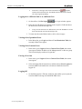
Main Window Overview ............................................................................61
The Boards Page ....................................................................................... 61
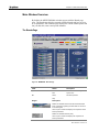
The Channels Page ................................................................................... 62
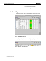
The Platform Page ..................................................................................... 63
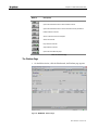
Buttons and Displays ................................................................................. 68
Setting SAP (Session Announcement Protocol) .......................................69
Setting NTP (Network Time Protocol).......................................................71
Viewing and Setting Service Parameters..................................................73
Tools .......................................................................................................... 73
Host Controller Boards............................................................................... 73
Switch Boards ............................................................................................ 75
Encoders .................................................................................................... 75
Encoder I/O Boards.................................................................................... 78
DVB Recasters and DVB Transraters........................................................ 84
DVB Transcoders....................................................................................... 88
Creating and Editing a Channel Profile.....................................................90
Adding Channels........................................................................................ 90
Viewing Channels ...................................................................................... 95
Editing Channels ........................................................................................ 97
Removing Channels................................................................................... 97
Managing Templates.................................................................................. 98
Managing Configurations ........................................................................... 98
Live Encoding Parameters......................................................................104
Input Parameters...................................................................................... 104
Encoding Parameters............................................................................... 104
DVB Recasting/Transrating Parameters.................................................127
DVB Input................................................................................................. 127
MPEG-1/2 Transrating ............................................................................. 128
DVB Transcoding Parameters ................................................................129
Input Parameters...................................................................................... 129
Encoding Parameters............................................................................... 129
H.264 Pass Through Parameters............................................................. 129
Target Parameters..................................................................................136
UDP Targets ............................................................................................ 136
Secondary Stream Targets ...................................................................... 139
Version Management..............................................................................141
Operating Channels................................................................................143
Transmitting Channels ............................................................................. 143
Stopping Channels................................................................................... 143
In Case of Problems ...............................................................................144
Alarms ...................................................................................................... 144
Where to find Error Messages ................................................................. 144
Reports ...................................................................................................145
System Specifications..........................................................................146
Chassis ...................................................................................................147
Physical.................................................................................................... 147
Enviornmental .......................................................................................... 147
Electrical Characteristics.......................................................................... 148
Safety Standrads...................................................................................... 148
Host Controller Units...............................................................................149
Host Service Board - MGCS-5500 ........................................................... 149
Host I/O Board - MGCI-5500.................................................................... 150
Switch .....................................................................................................151
Interphase ................................................................................................ 151
Intel Switch............................................................................................... 151
H.264 Encoder........................................................................................152
Service Board - MGES-5610.................................................................... 152
MPEG Encoder.......................................................................................156
Service Board - MGES-5200.................................................................... 156
Live Input ................................................................................................159
Analog I/O Board - MGEI-5210A.............................................................. 159
Digital I/O Board - MGEI-5210D............................................................... 159
DVB Input - Transcoding ........................................................................161
I/O Board - MGTI-5210X .......................................................................... 161
DVB Recaster/Transrater .......................................................................162
Service Board DVB Recaster - MGRS-5200............................................ 162
Service Board DVB Transrater - MGTR-5200.......................................... 162
I/O Board - MGRI-5200 ............................................................................ 162
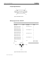
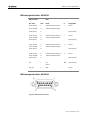
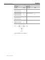
Pinout Specifications ..............................................................................164
MGI Analog Audio Cable - WCA5197 ...................................................... 164
MGI Analog Audio Cable - WCA5196 ...................................................... 165
MGI Analog Audio Cable - WCA5199 ...................................................... 165
Maintenance ..........................................................................................167
Troubleshooting ......................................................................................168
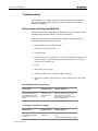
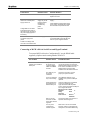
While Installing and Configuring MGW x100............................................ 168
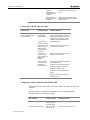
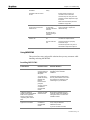
Using MGW EMS ..................................................................................... 171
Alarms ....................................................................................................176
Major ........................................................................................................ 176
Minor ........................................................................................................ 179
Warning.................................................................................................... 179
Error Messages ......................................................................................181
Replacing Hardware Components ..........................................................182
Replacing a Board.................................................................................... 182
Replacing the Host Controller's Flash Disk .............................................. 184
Replacing Fuses ...................................................................................... 186
Replacing a Power Supply ....................................................................... 187
Technical Support...................................................................................188
Hardware Warranty...............................................................................189
Index ......................................................................................................191
Chapter 1
Installation Guide
In This Chapter
y
System Overview
6
y
System Components
8
y
Hardware Overview
11
y
Installing Hardware
27
y
Connecting MGW x100 32
y
Configuring MGW x100 39
y
Installing Software
50
Chapter 1 • System Overview
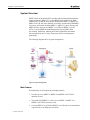
System Overview
MGW x100 is an integrated IPTV encoding and streaming platform that lets
carriers stream top quality TV over broadband IP networks such as xDSL,
LMDS and FTTx. MGW x100 encodes and transmits MPEG-1, MPEG-2 or
MPEG-4 AVC/H.264 video channels in real-time. It transcodes DVB MPEG2 sources to all formats including MPEG-1 / MPEG-2 at lower bit-rates and
MPEG-4/H.264, and converts MPEG-2 over DVB to MPEG-2 over IP
(DTA). A single SNMP Element Management System (EMS) offers
provisioning, monitoring, alarming and control capabilities and enables
smooth integration into a variety of networks and access management
applications.
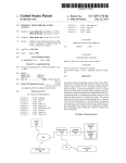
The following diagram shows a typical configuration.
Figure 1 :Typical Configuration
Main Features
Full redundancy on all components including channels.
6 System Overview
y
Encodes up to two MPEG-1, MPEG-2 and MPEG-4 AVC/H.264
channels per slot.
y
Transcodes DVB MPEG- 2 sources to two MPEG- 1, MPEG- 2 or
MPEG-4 AVC/H.264 streams per slot.
y
Converts MPEG-2 over DVB to MPEG-2 over IP at up to an accumulated
output bit-rate of 60 Mbps per slot (DTA).
Chapter 1 • System Overview
y
Converts and transrates MPEG-2 over DVB to five MPEG-2 over IP
channels.
y
Allows direct streaming of converted and transrated MPEG-2 over IP
channels.
y
Supports unicast, multicast and multi-unicast outputs.
y
Supports IP over Gigabit/100BT Ethernet.
y
Carrier grade cPCI 2.16 platform with hot-swap, hot-insertion of
removable components and VxWorks real-time OS.
y
Integrated solution with no single point of failure.
Note
MPEG-4 AVC/H.264 will be referred to as H.264 and DTA will be referred to as DVB
Recasting from this point on.
Available encoding capabilities depend on the hardware configuration and the version you
purchased.
System Overview 7
Chapter 1 • System Components
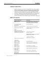
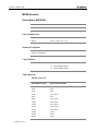
System Components
MGW 1100 consists of a 4U cPCI 2.16 chassis with 8 slots at the front and
the rear. The entire platform is based on IP architecture that contains service
and I/O boards. The MGW 1100 chassis and management application offer
redundancy for power supplies and service units. The SNMP based EMS
management application configures and operates MGW 1100 from any PC on
the network. Additional peripheral components are needed to configure and
operate MGW 1100. Required components are listed in the following
sections. If not otherwise noted, Optibase supplies the respective components.
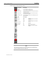
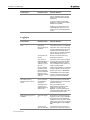
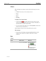
MGW 1100 Components
Chassis Components
Description
MGW 1100 chassis
Accommodates one host, one switch and 6
service boards with corresponding I/O boards.
Fans and power supplies are pre-installed.
19” rack-mount chassis
Rack-mounts MGW 1100.
Host Controller
MGCS-5500 Host Controller board (front)
Connects to the switch and to the network.
MGCI-5500 Host I/O board (rear)
Configures and manages the host controller and
the MGW 1100 unit.
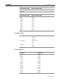
Switch
(MGW 1100 supports both:
Intel MGSS-1000 and Interphase 1500
(Interphase) Switch boards (front)
Connects to the host controller :
Intel switch – By cable
Interphase switch - through back plain (Provides
interfaces for technician use).
Intel switch - not required
MGSI-1100 Switch I/O board (rear)
Interphase switch - not required
H.264 Encoder
MGES-5610 (front)
Encodes H.264 streams.
MGEI-5210A (rear)
Connects analog video and audio sources.
MGEI-5210D (rear)
Connects digital video and audio sources.
MPEG Encoder
MGES-5200 (front)
Encodes MPEG-1 and 2 streams.
MGEI-5210A (rear)
Connects analog video and audio sources.
MGEI-5210D (rear)
Connects digital video and audio sources.
DVB Recaster
MGRS-5200 (front)
Recasts DVB to IP compliant streams.
MGRI-5200 (rear)
Connects DVB compliant video sources.
DVB Transrater
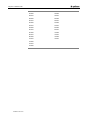
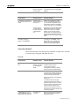
8 System Components
Chapter 1 • System Components
MGTR-5200 (front)
Transrates DVB to IP compliant streams.
MGRI-5200 (rear)
Connects DVB compliant video sources.
DVB Transcoder
MGES-5610 or MGES-5200 (front)
Re-encodes H.264 or MPEG streams.
MGTI-5210X (rear)
Connects and decodes DVB compliant video
sources.
Table 1: MGW 1100 Chassis and Service Components
Note
Install the host controller in the slot labeled Control and the switch in the slot labeled
Switch.
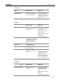
Cables
Description
Power cord
Connects MGW 1100 to AC power
(not supplied by Optibase).
12AWG copper conductor for DC power
supply
Connects MGW 1100 to DC power
(not supplied by Optibase).
12AWG copper conductor for system ground
Connects MGW 1100 to the system ground
(not supplied by Optibase).
Network cables (RJ45 cat 5e)
Connects MGW 1100 to 10/100/1000BT
network segments.
Connects the switch to the host
controller.(Intel switch only)
(not supplied by Optibase).
RJ45 cat 5e STP cable
Connects the host controller to the switch.
.(Intel switch only)
RS-232 null modem cables with two DB-9
type connectors
Connects a PC to MGW 1100's host
controller.
Video cable with BNC connector
Connects a Composite video source, a DVBASI compliant source or a video monitor to
MGW 1100.
(not supplied by Optibase).
2 MGI Analog audio cables per encoder
Connects a balanced or unbalanced audio
source to an encoder.
2xBNC to MiniDIN Cable
Connects an S-Video source to an encoder.
2 MGI Decoder cables per DVB transcoder
Connects speakers or earphones to a DVB
transcoder.
Table 2: MGW 1100 Cables
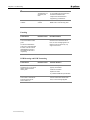
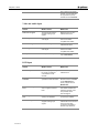
Software Components
Description
MGW EMS
Installs on a PC on the network and manages MGW 1100.
The PC with MGW EMS installed is referred to as
Management PC.
Command line interfaces
Lets you set and change basic parameters via
HyperTerminal or Telnet.
System Components 9
Chapter 1 • System Components
Table 3: MGW 1100 Software Components
Power Supply
MGW 1100 is available for AC or dual DC power. Depending on the
platform you purchased, the power supplies operate at 100-240V AC or dual
36-72V DC. Dual DC inputs ensure continued power supply if one DC source
fails.
The power supplies can be replaced while operating as explained in the
maintenance manual.
Note
y
Before installing power supplies, verify that the required voltage is supported in the
relevant location.
y
Make sure that you never insert DC power supplies into an AC powered platform and
vice versa.
y
Make sure that you never insert AC and DC power supplies into the same platform as
this will severely damage MGW 1100 and cause personal injury.
y
If necessary, replace power supplies one by one or switch MGW 1100 off before
replacing.
Peripheral Components
To configure network settings and receive streams, you need peripheral
components, which you may purchase from Optibase if not otherwise noted.
Required Components
Description
PC (Windows 2000 or XP) on the
network.
This PC must have MGW EMS installed
and is referred to as Management PC.
Manages and operates MGW 1100 using MGW
EMS. This PC also accesses MGW 1100 via
Telnet to configure basic parameters
(not supplied by Optibase).
Optional Components
Description
PC (Windows 2000 or XP) with a free
serial port
Connects to MGW 1100's COM1 and uses
MGW 1100's command line interface to
configure basic network settings via
HyperTerminal
(not supplied by Optibase).
IP compliant set top box
Decodes MPEG-1 and 2 streams. Contact
Optibase for supported set top boxes.
Table 4: MGW 1100 Chassis Components
Note
If you use MGW 1100's command line interface, do not try to configure parameters other
than those listed in the command line interface's help.
10 System Components
Chapter 1 • Hardware Overview
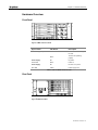
Hardware Overview
Front Panel
Figure 2 :MGW 1100 Front Panel
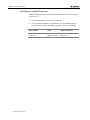
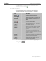
System LEDs
LED Status
Description
Fan Status (Optional)
Off
At least one fan is running
too slow.
Green
The fans are operating
properly.
Power Supply:
Off
No power.
Power LED
Green
Power on.
Power Supply:
Off
No error or no power.
Error LED
Yellow
Power supply error.
Table 5: LEDs on MGW 1100 Front Panel
Rear Panel
Figure 3 :MGW 1100 Rear
Hardware Overview 11
Chapter 1 • Hardware Overview
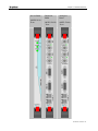
Service and I/O Boards
y
MGW 1100 accommodates up to six live encoders, DVB recasters, DVB
transraters or DVB transcoders. Some boards are available as standard or
premium versions. The premium version offers all services available for
the relevant board while the standard version offers selected services.
Available services can be found on the associated Service Board
parameter page. For additional information, refer to the user manual. The
various boards install into the following slots: the host controller is
installed in the slot labeled Control.
y
The switch service board is installed in the slot labeled Switch at the
front. In systems using the Interphase switch the I/O board is not in use
anymore.
y
Encoders, transcoders, transraters and recasters are installed in slots 3-8.
The following pages describe MGW 1100 service and I/O boards.
Note
y
Make sure to install boards in the correct slots. Otherwise MGW 1100 will not operate
properly.
y
Make sure to install only boards that are associated with MGW 1100. If you try to install
and operate boards from third parties, not explicitly authorized by Optibase, MGW 1100
may fail and your warranty will become void.
y
Make sure to install corresponding service and I/O boards in the matching front and
rear slots respectively.
y
Make sure to cover all empty slots with slot covers.
y
Make sure to remove and install the host controller and/or the switch only when the
MGW 1100 unit is switched off.
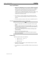
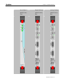
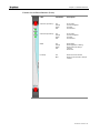
H.264 Encoder
The H.264 encoder boards can be installed in:
12 Hardware Overview
y
MGW 5100: slots 1 - 6 and 11 - 17.
y
MGW 1100: slots 3 - 8.
y
MGW 1000: slot 1.
y
Each H.264 encoder supports two video channels and up to two audio
channels per video channel.
y
For explanations on connectors and LEDs, click the relevant connector or
LED.
Chapter 1 • Hardware Overview
Service Board
(MGES-5610) Front
Digital I/O
Board
Analog I/O
Board
(MGEI-5210D)
- Rear
(MGEI-5210A)
- Rear
Hardware Overview 13
Chapter 1 • Hardware Overview
Related Topics
y
Analog Input Parameters
y
Digital Input Parameters
y
H.264 Encoding Parameters
y
Targets
y
H.264 Encoder Service Board Parameters
y
Encoder I/O Board Parameters
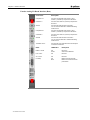
MPEG Encoder
The MPEG encoder boards can be installed in:
14 Hardware Overview
y
MGW 5100: slots 1 - 6 and 11 - 17.
y
MGW 1100: slots 3 - 8.
y
MGW 1000: slot 1.
y
Each MPEG encoder supports two video channels and up to two MPEG
audio channels per video channel.
y
For explanations on connectors and LEDs, click the relevant connector or
LED.
Chapter 1 • Hardware Overview
Service Board
Digital I/O Board
Analog I/O Board
(MGES-5200) Front
(MGEI-5210D) Rear
(MGEI-5210A) Rear
Hardware Overview 15
Chapter 1 • Hardware Overview
Related Topics
y
Analog Input Parameters
y
Digital Input Parameters
y
MPEG Encoding Parameters
y
Targets
y
MPEG Encoder Service Board Parameters
y
Encoder I/O Board Parameters
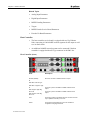
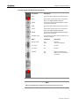
Host Controller
y
The host controller service board is equipped with two Gig. Ethernet
links, connecting 10/100/1000BT network segments for the output as well
as to an Intel switch.
y
An additional 1000SX network segment can be connected if the host
controller is equipped with an SC-type connector in the PMC slot.
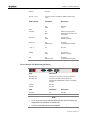
Host Controller (front)
Ports
Description
No PMC (Default)
Not used, connects a 1000SX network for output
Or
PMC Fiber: Left SC-Type
PMC Fiber : Right SC-Type
Or
PMC Copper: Upper Gig.
Eth. Ch B
PMC Copper: Lower Gig.
Eth. Ch A
16 Hardware Overview
Connects up to two 10/100BT or 1000BT networks for the
output.
Connects up to two 10/100BT or 1000BT networks for the
output.
VGA
Connects a monitor to the MGW x100 unit. Use this connector
only if Optibase instructed you to do so.
COM1
Connects the Configuration PC to the host controller for
configuration using HyperTerminal.
Chapter 1 • Hardware Overview
USB 2.0
Not used.
Gig. Eth. 1 and 2
Connects up to two 10/100BT or 1000BT networks for the
output
LEDs (left slot)
LED Status
Description
Off
Green
Not active
Active
Hot Swap
Off
Blue
Board cannot be removed.
Board can be removed or was
just inserted.
PMC: LNK
Off
Green
No connection
Network connected
PMC: ACT
Off
Flashes green
No activity
Transmitting/receiving data
I, II (0 – 7)
Off
Not used
SPEED
Off
Green
No connection
Network connected
ACT
Off
Flashes orange
No activity
Transmitting/receiving data
PWR
Host Controller I/O Board Interface (Rear)
Ports
Description
Gig. Ethernet A
Connects the cross cable to the service board I/O.
Gig. Ethernet B
Connects a 10/100BT network segment for
management via MGW EMS and basic configuration
via Telnet.
COM A
Not used.
COM B
Not used.
LEDs
LED Status
Description
Hot Swap
Off
Not used
Note
y
Do not use any host controller other than MGCS-5500. Any other host controller may
damage MGW x100 and renders your warranty void.
y
The host controller and switch are not hot swappable.
Hardware Overview 17
Chapter 1 • Hardware Overview
Live Encoder
18 Hardware Overview
y
Install live encoders in slots 3-8.
y
MPEG and H.264 encoders support two video channels and up to two
audio channels per video channel.
Service Board
Video
Required I/O Board
MGES-5200
MPEG-1 and 2
MGEI-5210A (analog sources) or
MGEI-5210D (digital sources)
MGES-5610
H.264
MGEI-5210A (analog sources) or
MGEI-5210D (digital sources)
Chapter 1 • Hardware Overview
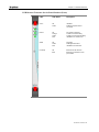
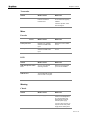
Encoder Service Board Interface (Front)
LEDs
LED Status
Description
Active CH1 (Encoder 1)
Off
Orange
Green
Red
No encoding
Encoder configured
Encoding
Encoder error
Active CH2 (Encoder 2)
Off
Orange
Green
Red
No encoding
Encoder configured
Encoding
Encoder error
Status
Off
Orange
Green
Red
Board offline
Board application is starting
Board online and ready to
transmit
Board error
Hot Swap
Off
Blue
Board cannot be removed.
Board can be removed or was just
inserted.
Hardware Overview 19
Chapter 1 • Hardware Overview
Encoder Analog I/O Board Interface (Rear)
20 Hardware Overview
Connectors
Description
Composite A Y
Connects a Composite video source or an SVideo's Y (Luminance) component to Encoder 1.
S-Video A C
Connects an S-Video's C (Chroma) component to
Encoder 1.
Audio A
Connects two audio sources to Encoder 1.
You can connect balanced or unbalanced analog
audio sources.
Composite B Y
Connects a Composite video source or an SVideo's Y (Luminance) component to Encoder 2.
S-Video B C
Connects an S-Video's C (Chroma) component to
Encoder 2.
Audio B
Connects two audio sources to Encoder 2.
You can connect balanced or unbalanced analog
audio sources.
10/100BT 1 and 2
Connects the cross cable from service board port 2
to the service board I/O.
LEDs
LED Status
Description
Detect A and B
Off
Green
No source.
Video source detected.
Link 1 and 2
Off
Not used.
Act 1 and 2
Off
Not used.
Hot Swap
Off
Blue
Board cannot be removed.
Board can be removed or was
just inserted.
Chapter 1 • Hardware Overview
Encoder Digital I/O Board Interface (Rear)
Connectors
Description
SDI A
Connects an SDI compliant video source to Encoder
1.
Loop A
Ports the SDI compliant video source, connected to
SDI A, to an additional MGEI-5210D board.
AES3 A
Connects two balanced AES3 (AES/EBU) compliant
audio sources to Encoder 1.
SDI B
Connects an SDI compliant video source to Encoder
2.
Loop B
Ports the SDI compliant video source, connected to
SDI B, to an additional MGEI-5210D board.
AES3 B
Connects two balanced AES3 (AES/EBU) compliant
audio sources to Encoder 2.
10/100BT 1 and 2
Connects the cross cable from service board port 2 to
the service board I/O.
LEDs
LED Status
Description
Detect A and B
Off
Green
No source.
Video source detected.
Link 1 and 2
Off
Not used.
Act 1 and 2
Off
Not used.
Hot Swap
Off
Blue
Board cannot be removed.
Board can be removed or was
just inserted.
Note
Make sure that digital input is enabled for the associated encoder service board.
Hardware Overview 21
Chapter 1 • Hardware Overview
DVB Recaster and DVB Transrater
Install DVB Recaster Service boards from the front and I/O boards from the
rear in slots 3-8.
22 Hardware Overview
y
For board parameters, refer to the user manual.
y
You can add and transmit several channels. The accumulated bit-rate
depends on the board in use and the capabilities level you purchased.
Service Board
Video
Required I/O Board
MGRS-5200
MPEG-2 over DVB
MGRI-5200
MGTR-5200
MPEG-2 over DVB
MGRI-5200
Chapter 1 • Hardware Overview
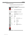
DVB Recaster/Transrater Service Board Interface (Front)
LEDs
LED Status
Description
ASI In
Off
Green
Initialized.
DVB-ASI compliant source
connected.
Demux
Off
Orange
Green
Red
No channel configured.
At least one channel ready.
At least one channel transmitting.
Initialization or channel error.
Status
Off
Green
Red
Not active.
DVB application active.
Initialization or board error.
Hot Swap
Off
Blue
Board cannot be removed.
Board can be removed or was
just inserted.
Hardware Overview 23
Chapter 1 • Hardware Overview
DVB I/O Board Interface (Rear)
y
You can connect a network to the connector labeled 10/100 BT 1 for
transmitting content directly from the I/O board to the network.
y
For board parameters, refer to the user manual.
Connectors
Description
ASI Monitor
Connects a DVB compliant decoding device to
preview an incoming DVB-ASI compliant stream.
ASI 1 In - ASI
2 In
Each interface can connect to one DVB-ASI
compliant source.
ASI 3 In - ASI
4 In
Each interface can connect to one DVB-ASI
compliant source.
In previous versions of this board, ASI 3 In and ASI 4
In may not be supported.
10/100BT 1
Connects a network segment for the output of direct
streaming.
10/100BT 2
Not used.
LEDs
Descript
ion
ASI 1 In - ASI
4 In
Off
Green
No Source or not used.
DVB-ASI compliant source detected.
Link 1
Off
Orange
No connection
Connected
Act 1
Off
Flashes
Green
No transmission
Transmission
Link 2
Off
Not used.
Act 2
Hot Swap
24 Hardware Overview
Not used.
Off
Blue
Board cannot be removed.
Board can be removed or was just
inserted.
Chapter 1 • Hardware Overview
DVB Transcoder
A DVB transcoder consists of a DVB transcoder I/O board and an encoder
service board. Service boards install from the front and I/O boards from the
rear in slots 3-8.
y
For board parameters, refer to the user manual.
y
Each DVB transcoder supports two video channels and up to two audio
channels per video channel.
I/O Board
Video
Required Service Board
MGTI-5210X
MPEG-2 over DVB to
MPEG-2 or H.264 over IP
MPEG-2: MGES-5200
H.264:
MGES5610
Encoder Service Board (Front)
y
For encoder service board interfaces, refer to Encoder Service Board
Interface (Front) (on page 18).
y
For encoder service board parameters, refer to the user manual.
Hardware Overview 25
Chapter 1 • Hardware Overview
DVB Transcoder I/O Board Interface (Rear)
Connectors
Description
ASI 1 In
Connects DVB-ASI compliant source.
ASI 2 In
Connects DVB-ASI compliant source.
Video A and B
Connects a monitor for preview. This monitor must have a
Composite video input.
Audio A and B
Connects a monitor for preview. This monitor must have
an Unbalanced audio input.
10/100BT 1 and 2
Connects the cross cable from service board port 2 to the
service board I/O.
LEDs
Description
ASI 1 In
Off
Green
No Source
DVB-ASI compliant source detected.
ASI 2 In
Off
Green
No Source
DVB-ASI compliant source detected.
Link 1 and 2
Off
Not used.
Act 1 and 2
Off
Not used.
Hot Swap
Off
Blue
Board cannot be removed.
Board can be removed or was just
inserted.
Note
DVB Transcoder I/O boards with a Loop connector instead of the second DVB-ASI input
interface are available and referred to as MGTI-5210.
26 Hardware Overview
Chapter 1 • Installing Hardware
Installing Hardware
An Optibase engineer may assemble and install your MGW x100 unit at your
site. If MGW x100 has been sent to you or you wish to change MGW x100’s
location or its hardware configuration at a later stage, follow the instructions
below.
General Tasks
y
Review all safety recommendations and guidelines.
y
Verify the site’s power voltage and make sure that MGW x100’s power
supplies comply with it.
y
Verify the site’s environmental specifications and make sure that they
comply with the requirements stated in the system spec.
y
Verify that you have the required cables and peripheral components
available in the desired location.
Required Tools
y
Number 2 Phillips screwdriver
y
5×100 Phillips screwdriver
y
Tape measure
y
Level (optional)
Rack-Mounting MGW x100
To mount MGW x100 into a rack:
1. Make sure that your rack has a rail with mounting holes on the inside of
the rack.
Make sure that MGW x100’s rear will be easily accessible for installing
and removing components such as boards, fans and cables.
2. Measure the distance between the screw holes and insert the screw
brackets into the mounting holes accordingly.
3. With the help of at least three people, place the MGW x100 chassis into
the desired position. Ensure that the mounting holes in the rack match the
corresponding holes in the chassis.
4. Make sure that at least two people hold the chassis while a third person
bolts the chassis to the rack. Bolt the bottom holes first and then work up
from there.
Installing Hardware 27
Chapter 1 • Installing Hardware
To remove MGW x100 from a rack:
1. Make sure to switch off MGW x100 and disconnect all cables.
2. Make sure that two people are holding the unit and then use a Number 2
Phillips screwdriver to loosen the screws that hold MGW x100 in the
rack.
3. With the assistance of two people, carefully remove the unit from the
rack.
Note
y
To stabilize the rack and prevent it from falling, we recommend mounting MGW x100
and other heavy equipment into the lower half of your rack.
y
Make sure that MGW x100 is switched off and all cables are disconnected when rackmounting or removing MGW x100 from a rack.
y
Never attempt to lift or move MGW x100 by yourself. Make sure that at least three
people lift the chassis.
Installing Service and I/O Boards
MGW 1100 ships with pre-installed fans and power supplies. Associated
service and I/O boards ship separately and must be installed before you can
connect external components and configure MGW 1100.
Certain boards require certain slots as listed below. Slot labels can be found
to the right of each slot. If not otherwise noted, every service unit consists of
a service board and an I/O board installed in a specific slot from the front and
the rear respectively.
Boards
Slots
Host controller
Control
Switch
Switch
MPEG Encoder,
H.264 Encoder,
DVB Recaster,
DVB Transrater,
DVB Transcoder
3-8
Table 6: Slot Assignments
To install boards for the first time:
Install the desired boards for first use while MGW 1100 is switched off.
Associated service and I/O boards must be installed into matching slots from
the front and the rear respectively.
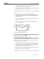
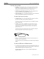
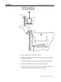
1. Use a 5100 ׳Phillips screwdriver to loosen the screws on the right and the
left of the relevant slot cover on MGW 1100’s front panel. Loosen the
28 Installing Hardware
Chapter 1 • Installing Hardware
screws only until you feel a click. If you unscrew any further, you will
not be able to open the injector/ejector handles.
2. Push the red buttons on the ejector/injector handles at the same time and
open them; the respective slot cover unplugs.
3. Remove the slot cover and insert the desired service board into the chosen
slot.
4. Plug the service board into the bus connector and close the
ejector/injector handles; you hear a click and the Hot Swap LED turns
blue when the board has been properly inserted. The board must line up
with the chassis surface.
5. Use the 5 100 ׳Phillips screwdriver to tighten the screws on the right and
the left side of the I/O board.
6. Locate the corresponding I/O slots on the rear panel and follow steps 1 –
5 to install the I/O board.
Figure 4 :Opening the Ejector/Injector Handle
Note
Make sure to cover all empty slots with slot covers.
To install boards while operating MGW 1100:
All boards except the host controller and the switch can be removed and
installed while MGW 1100 is operating.
1. Use a 5100 ׳Phillips screwdriver to loosen the screws on the right and the
left of the relevant slot cover on MGW 1100’s front panel. Loosen the
screws only until you feel a click. If you unscrew any further, you will
not be able to open the injector/ejector handles.
2. Push the red buttons on the ejector/injector handles at the same time and
open them; the respective slot cover unplugs.
3. Remove the slot cover and insert the desired service board into the chosen
slot.
Installing Hardware 29
Chapter 1 • Installing Hardware
4. Remove the slot cover and insert the desired service board into the chosen
slot.
5. Plug it into the bus connector and close the ejector/injector handles; you
hear a click and the Hot Swap LED turns blue when the board has been
properly inserted. The board must line up with the chassis surface.
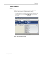
6. Use the 5 100 ׳Phillips screwdriver to tighten the screws on the right and
the left side of the I/O board.
7. Wait until the Hot Swap LED turns off before using this board.
Note
y
The host controller and the switch are not hot swappable.
y
When you replace the DVB Transcoder I/O board, the associated encoder service
board resets after the new board has been installed.
y
Make sure to cover all empty slots with slot covers.
To remove boards:
All boards except the host controller and the switch can be removed and
installed while MGW 1100 is operating.
1. If you remove a hot swappable board and MGW 1100 is running, slightly
push the red button of the right ejector/injector handle down. When the
Hot Swap LED turns blue, the board is ready to be removed.
2. Use the 5100 ׳Phillips screwdriver to loosen the screws on the right and
the left side of the relevant slot cover on MGW 1100’s front panel.
Loosen the screws only until you feel a click. If you unscrew any further,
you will not be able to open the injector/ejector handles.
3. Push the red buttons on the ejector/injector handles at the same time and
open the ejector/injector handles; the board unplugs.
4. Remove the relevant board.
5. Cover the open slot with a slot cover and close the ejector/injector
handles; you hear a click when the slot cover has been properly inserted.
6. Tighten the screws on the right and the left side.
30 Installing Hardware
Chapter 1 • Installing Hardware
Note
y
The host controller and the switch are not hot swappable.
y
When you replace the DVB Transcoder I/O board, the associated encoder service
board resets after the new board has been installed.
y
Make sure to cover all empty slots with slot covers.
Installing Hardware 31
Chapter 1 • Connecting MGW x100
Connecting MGW x100
You have to connect certain components to one another and to networks. To
do so, follow the instructions below.
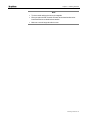
Connecting MGW 1100 to the Power Supply
y
AC Platform. Use a UL listed power cord and connect it to the power
connector on MGW 1100's rear panel. MGW 1100 does not ship with a
power cord. You will have to purchase a power cord that fits your local
Din socket.
y
Dual DC Platform. Use AWG12 copper conductors and connect Plus,
Minus and Ground to the connectors labeled +, - and GND respectively
on MGW 1100's rear panel.
If you connect both DC inputs to separate DC sources, the second DC
source takes over if the first one fails.
y
System Ground. Use an AWG12 copper conductor and attach it to one
of the System Ground studs on the bottom of MGW 1100's rear panel.
The System Ground studs are labeled with
Connecting Host Controllers with Switches
y
The host controller connects to the switch internally.
32 Connecting MGW x100
.
Chapter 1 • Connecting MGW x100
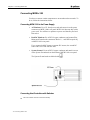
Connecting to a Network for Management
Connect a 10/100 BT network segment to the NIC labeled Gi. Ethernet B
located on the host controller I/O board (rear).
Connecting to Networks and Devices for the Output
By default, MGW 1100 and MGW 1000 comes with two Giga Ethernet links.
An additional SC-type/Copper modules are optional. Straming is also
possible through the rear I/O boards - DVB recasters and DVB transraters.
To connect 10/100/1000BT network segments:
y
Connect up to two 10/100BT network segment used for the output to the
Giga Ethernet links labeled Gig. Eth. 1 and 2 respectively.
To connect a 1000SX network segment:
y
Use an optic cable and connect one end to the SC-type connector to the
right in the PMC slot and the other end to an IEEE 802.3z compliant
gigabit switch.
y
Make sure to connect Rx to Tx and Tx to Rx; otherwise MGW 1100 and
MGW 1000 cannot connect to the network.
Connecting MGW x100 33
Chapter 1 • Connecting MGW x100
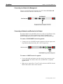
To connect a 10/100/1000 BT Copper network segment:
y
Connect up to four 10/100/1000BT network segment used for the output
to the Giga Ethernet links labeled Gig. Eth. 1 and 2 or PMC Ch A and B.
To connect a network segment to a DVB I/O board:
y
34 Connecting MGW x100
Connect a 10/100BT network segment to the NIC labeled 10/100 BT 1
located on the DVB I/O board (rear).
Chapter 1 • Connecting MGW x100
Connecting Video and Audio
y
Encoding. Video and audio sources connect to the Encoder I/O board
MGEI-5210A or MGEI-5210D at the rear. MGEI-5210A connects to
analog sources and MGEI-5210D connects to digital sources.
y
DVB Recasting and DVB Transrating. DVB-ASI compliant sources
connect to the DVB I/O board MGRI-5200 at the rear.
y
DVB Transcoding. Up to two DVB-ASI compliant sources and monitors
connect to the DVB I/O board MGTI-5210X at the rear.
To connect video sources to encoders:
y
Composite Video. Use a video cable with a BNC connector to connect
the source to the BNC connector labeled Composite A.
If required, connect the second Composite source to the BNC connector
labeled Composite B.
y
S-Video. Use the 2´BNC to MiniDIN video cable (WCA3132) and
connect the BNC connector labeled Y to the BNC connector labeled
Composite A Y and the BNC connector labeled C to the connector
labeled S-Video A C.
If required, connect the second S-Video source to the BNC connectors
labeled Composite B Y and S-Video B C respectively.
y
SDI. Use a video cable with a BNC connector to connect the source to
the BNC connector labeled SDI A.
If required, connect the second SDI source to the BNC connector labeled
SDI B.
To connect an SDI source to additional encoders:
y
Use a BNC cable and connect one end to the connector labeled Loop A or
Loop B respectively and the other end to connector SDI A or SDI B on an
additional MGEI5210D Encoder Digital I/O board.
You can connect an SDI source to up to six MGEI-5210D Encoder
Digital I/O boards.
Connecting MGW x100 35
Chapter 1 • Connecting MGW x100
Note
y
SDI is available for encoders, if digital input is enabled for the associated encoder
service board (MGES-5200).
y
Cables must be purchased separately.
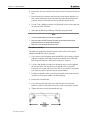
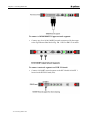
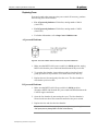
To connect audio sources to encoders:
y
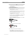
Balanced/Unbalanced: Use the desired MGI Analog Audio cable to
connect analog audio sources as follows:
y
Use the MGI Analog Audio Cable with XLR connectors (WCA5197) for
balanced sources or the MGI Analog Audio Cable with RCA connectors
(WCA5196) for unbalanced sources respectively.
y
Connect the DB-15 connector to the relevant audio connector (Audio A
or Audio B for Encoder 1 or 2 respectively).
y
Connect the connectors labeled Audio Right Ch. 1 and Audio Left Ch. 1
to the desired audio source. Depending on the cable you use, these
connectors are either XLR female or RCA.
y
If you use a second audio source, connect the connectors labeled Audio
Right Ch. 2 and Audio Left Ch. 2 to that source.
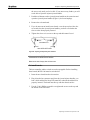
Figure 5 :MGI Analog Audio Cable with XLR Connectors (WCA5197(
Figure 6 :MGI Analog Audio Cable with RCA Connectors (WCA5196(
y
36 Connecting MGW x100
AES3 (AES/EBU): Use the MGI Analog Audio cable with XLR
connectors (WCA5197) to connect balanced AES3 audio sources to the
relevant audio connector AES3 A or AES3 B as explained above.
Chapter 1 • Connecting MGW x100
Note
y
The additional BNC connector labeled LTC is not used at present.
y
Embedded audio is part of the SDI input and does not require connecting an audio
source.
y
AES/EBU is available for encoders, if digital input is enabled for the relevant encoder
service board (MGES-5200).
y
Cables must be purchased separately.
To connect sources to DVB Recasters and DVB Transraters:
y
Use BNC cables to connect DVB-ASI compliant sources to the ASI In
connectors. Connect the first source to the BNC connector labeled ASI 1
In, the second source to ASI 2 In and so on.
To connect sources to DVB Transcoders:
y
Use BNC cables to connect up to two DVB-ASI compliant sources to the
BNC connectors labeled ASI 1 In and ASI 2 In respectively.
To connect monitors for preview to DVB Transcoders:
y
Video. Use a BNC cable to connect monitors with Composite input to the
BNC connectors labeled Video A and/or Video B.
When re-encoding content using Transcoder 1, connect to Video A.
When re-encoding content using Transcoder 2, connect to Video B.
y
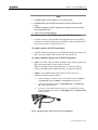
Audio. Use the MGI Decoder cable (WCA5199) to connect an
unbalanced audio monitor as follows:
y
Connect the DB-15 connector to the relevant audio connector (Audio A
for Transcoder 1 and/or Audio B for Transcoder 2 respectively).
y
Connect the XLR male connectors Audio Right Ch. 1 and Audio Left
Ch. 1 to the desired monitor.
y
If you use a second audio monitor to preview re-encoded audio content,
connect the XLR male connectors Audio Right Ch. 2 and Audio Left Ch.
2 to that monitor.
Figure 7 :MGI Analog Audio Cable with XLR Connectors (WCA5197(
Connecting MGW x100 37
Chapter 1 • Connecting MGW x100
Note
y
The interfaces ASI 3 In and ASI 4 In are not used in the Standard version of previous
versions.
y
DVB Transcoder I/O boards with a Loop connector instead of a second DVB-ASI input
interface are still available and referred to as MGTI-5210. The Loop connector allows
connecting the DVB input to additional DVB Transcoder I/O boards.
y
If you assign a hot stand-by channel to a DVB Transcoder and you are still using the
MGTI-5210, connect the relevant source separately to the relevant DVB Transcoder
I/O board's ASI In connector. Do not connect it via the primary channel's DVB
Transcoder I/O board's Loop connector.
y
Cables must be purchased separately.
To connect IP sources to Transcoders
y
38 Connecting MGW x100
Use RJ-45 network cable to connect IP source to port 25 in Switch A or B
depending on your redundancy configuration.
Chapter 1 • Configuring MGW x100
Configuring MGW x100
MGW x100's switches and host controller units are pre-configured. To avoid
IP address conflicts you must change the IP addresses of all NICs (Network
Interface Card). After you have installed and connected the relevant
components, you have to configure basic network parameters by using MGW
x100's command line interface.
Accessing MGW x100's Command Line Interface
When to use Hyper Terminal
Use Hyper Terminal in the following scenarios:
y
MGW x100 is used for the first time.
y
IP address of the network interface Gig. Ethernet Rear B is unknown.
Use Hyper Terminal to access MGW x100's command line interface and set
the network parameters for the network interface labeled Gig. Ethernet Rear
B on Controller A’s I/O board (rear). This network interface connects the
network segment used for managing MGW x100.
When to use Telnet
y
Use Telnet when the IP address of the network interface Gig. Ethernet
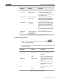
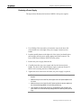
Rear B is known.
Note
MGW x100 EMS application can be also used for the configuration of the network
interfaces.
Using HyperTerminal
Before using MGW x100 for the first time, you have to assign an IP address
and a network mask to the Management Network interface Gig. Ethernet
Rear B on Controller A and change the host controller (system) name.
If you wish to manage the MGW from a different network then you must
configure the default gateway
Each network interface has an Interface ID assigned that is required for
setting network parameters. The Interface ID for Gig. Ethernet Rear B is 4.
Configuring MGW x100 39
Chapter 1 • Configuring MGW x100
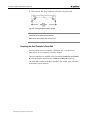
Preliminary steps
1. Verify that MGW x100 is switched on and the Management network
segment is connected to the network interface labeled Gig. Ethernet
Rear B on Controller A’s I/O board (rear).
2. Verify that at least one COM port is available on the relevant PC.
3. Use the supplied a DB-9 cable (Null Modem cable) and connect one end
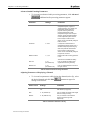
to MGW x100's serial port labeled COM1 on Controller A (front) and the
other end to the relevant COM port on your PC.
4. Switch MGW x100 on. It will take few minutes until MGW x100
completes booting.
Note
Although you can connect to MGW x100 while MGW x100 is booting, you cannot issue
commands.
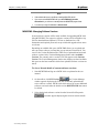
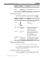
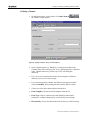
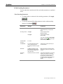
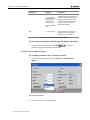
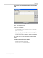
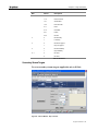
To access MGW x100 via HyperTerminal:
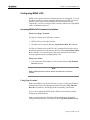
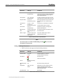
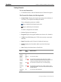
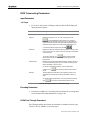
1. Open Hyper Terminal; the Connection Description window appears.
If you are using a previously saved connection (*.ht file), continue with
step 6.
40 Configuring MGW x100
Chapter 1 • Configuring MGW x100
If you are creating a new connection, proceed to the next step.
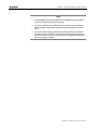
Figure 8 :Hyper Terminal Connection Description window
Configuring MGW x100 41
Chapter 1 • Configuring MGW x100
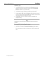
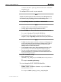
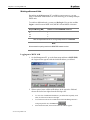
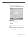
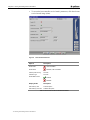
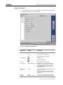
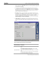
2. In the Name field type the desired name (e.g. MGWx100) and click OK;
the Connect To window appears.
Figure 9 :HYper Terminal>Connect To window
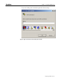
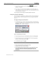
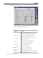
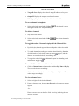
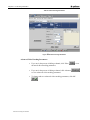
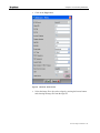
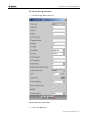
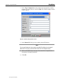
3. In the Connect To window, click the Connect Using drop-down list,
select the appropriate COM port and click OK.
The COM<x> Properties window appears.
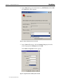
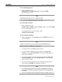
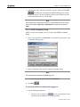
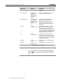
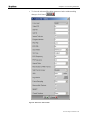
Figure 10 :HyperTerminal's COM Properties window
42 Configuring MGW x100
Chapter 1 • Configuring MGW x100
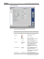
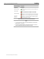
4. Type the parameters into their respective fields as shown in the figure
above and click OK.
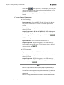
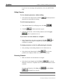
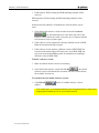
5. Press ENTER and wait until the Hyper terminal command prompt
appears (MGWx100>).
User mode is enabled.
y
y
User mode - enables you to use basic commands. This mode is not suffici
configuration.
y
Tech mode - enables you to use more advanced technical commands. This
MGWx100 configuration.
Messages (including error messages) may appear on your screen. To prevent the display of these messa
keyboard and press ENTER. the Printouts Disabled message appears on the screen. To enable the dis
trouble-shooting purposes) press s again and then ENTER.
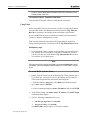
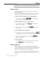
6. At the MGWx100 prompt type tech (lower case).
7. Type mgw5100 for the user name. Press ENTER.
8. Type optibase for the password. Press ENTER.
The following message is displayed: "technician" and the prompt
changes to DEBUG>.
Note
Commands entered at the Hyper Terminal prompt are case sensitive. Follow the instructions
exactly as described.
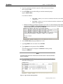
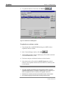
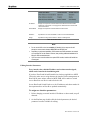
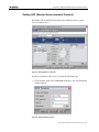
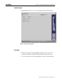
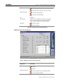
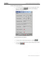
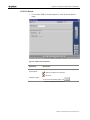
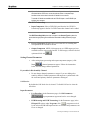
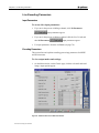
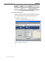
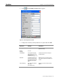
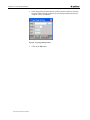
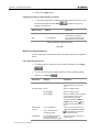
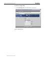
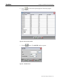
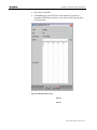
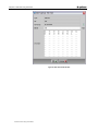
9. Type ipConfig. The NICs identity parameters (such as Alias, IP address
and status) are displayed.
Figure 11 :Hyper Terminal ipConfig window
Configuring MGW x100 43
Chapter 1 • Configuring MGW x100
As shown in the above figure Gig, Ethernet Rear B is the card used for
managing the unit.
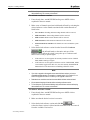
To configure NICs to work on your network:
Note
The MGW x100 platform requires two network connections; one for Management and one
for IP video stream inputs. The NICs on the front are used for streaming. You may change
their IP address by using the ipConfig command or the MGW EMS application.
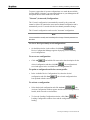
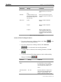
1. Type ipConfig <interface> <ip address> <subnet mask>.
Note
y
If required consult your network administrator to obtain these parameters.
y
To avoid IP address conflicts change the IP addresses of all NICs.
2. Press ENTER twice. The new IP address and network mask are set.
For example: ipConfig 4 172.16.100.253 255.255.0.0
3. Verify that the IP address and the subnet mask have been properly
assigned by using the ipConfig command and checking the parameters.
Note
y
The MGW x100 platform requires two network connections; one for Management and
one for IP video stream inputs. Each must belong to a different subnet. The NICs on
the front are used for streaming. You may change their IP address by using the
ipConfig command or the MGW EMS application.
y
It is recommended you make a note of network parameters that have been set. For
your convenience, you can use the table in My Network Settings (on page 48).
y
If you wish to configure network interfaces for Controller B using HyperTerminal,
connect the Configuration PC to Controller B's serial interface labeled COM1 at the
front and follow the instructions above.
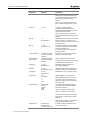
To set the community string:
y
In the command line, type
community <my_string> and press ENTER; the desired parameter is
set.
For example: community optibasemgw.
To set or change the MGW SNMP Mib identifier:
y
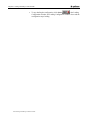
In the command line, type
setMib2 <Name> <Location> <Contact> and press ENTER; the
desired parameters are set.
For example: setMib2 System_A_Server_room_John_Doe
44 Configuring MGW x100
Chapter 1 • Configuring MGW x100
To set a default gateway:
y
In the command line, type
defaultGateway <default gateway IP> and press ENTER;
the default gateway is set.
Note
The default gateway applies only to the management network.
For example: defaultGateway 172.16.195.256
To set the time and date:
y
In the command line, type
setTime <hour> <minute> <day> <month> <year> and press ENTER;
the new date and time are set.
To set MGW x100 to 15.20h on April 3, 2009:
setTime 15 20 03 04 2004
To view the time and date:
y
In the command line, type showTime and press ENTER; the time and
date are displayed.
Note
Viewing the time and date can be also performed using the MGW EMS application.
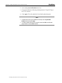
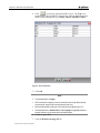
To view and issue additional commands:
1. To enter the menu, type help; the menu appears.
2. To view available commands for your selection, type help <your
selection>, for example help TCP/IP; the relevant commands appear
with a short explanation.
3. To view the required syntax for the desired command, type help <the
desired command>, for example help ipConfig; the required syntax
appears with an example.
4. To issue the desired command, type the command with the required
syntax and press ENTER; the command is executed.
Note
y
We recommend configuring Controller B's interfaces using MGW EMS, although you
may use HyperTerminal after connecting the Configuration PC to Controller B's serial
port (COM1).
y
If you have Controller B and Switch B installed as a backup (hot standby), make sure to
Configuring MGW x100 45
Chapter 1 • Configuring MGW x100
assign the network interface for the management on Controller B to the same subnet
as Host A, otherwise MGW EMS will be unable to switch over to Controller B in case
Controller A and/or switch A fail.
To terminate Hyper Terminal connection:
Close the HyperTerminal's window to terminate the connection.
Using Telnet
Before using MGW x100 for the first time, you have to assign an IP address
and a network mask to the Management Network interface Gig. Ethernet
Rear B on Controller A and change the host controller (system) name.
If you want MGW x100 to be accessible from outside your local network,
you have to assign a default gateway as well.
Each network interface has an Interface ID assigned that is required for
setting network parameters. The Interface ID for Gig. Ethernet Rear B is 4.
Preliminary steps
1. To access MGW x100 via Telnet, use the network segment connected to
Gig. Ethernet Rear B on the Host Controller I/O board (rear). Refer to
your notes for the relevant IP address. Gig. Ethernet Rear B is located
on Controller A’s I/O board (rear).
Note
If you have a second host controller unit installed in the slot labeled Control B as a backup
(hot standby), connect the management network segment to its 10/100/1000BT 1 connector
as well.
To access MGW x100 via Telnet:
1. Double-click the Telnet icon on the Desktop; The Telnet program opens.
If you don't have a shortcut to Telnet on the Desktop and you don't see
Telnet in the Program menu, perform the following steps:
a. From the Windows Start menu select Run and in the Run window
type "cmd" and press ENTER.
b. At the Command prompt type telnet <IP address> and press ENTER.
2. At the Telnet prompt, type telnet <unit's IP address>; the MGW Login
command prompt appears.
3. Type the following commands (lower case):
y
MGW Login: mgwtelnet. Press ENTER.
y
Password: security. Press ENTER.
The MGWx100> prompt appears. User mode is enabled.
46 Configuring MGW x100
Chapter 1 • Configuring MGW x100
Note
User mode enables you to use basic commands and is not sufficient for MGWx100
configuration. Tech mode enables you to use more advanced technical commands and is
sufficient for MGWx100 configuration
4. If required, change the User mode to Tech mode by typing the following
commands (lower case) a the MGWx100 prompt:
y
tech (lower case). Press ENTER.
y
mgw5100 for the user name. Press ENTER.
y
optibase for the password. Press ENTER.
The following message is displayed: " technician" and the prompt
changes to DEBUG>.
5. Follow the steps in Using HyperTerminal (on page 39) for configuring
the MGWx100 unit.
Note
y
If accessing MGW x100 for the first time or no IP address is available, connect a PC to
MGW x100's COM1 port and use HyperTerminal to access MGW x100's command line
interface. Refer to Using HyperTerminal (on page 39) for details.
y
Host controller units installed in the slot labeled Control B function as a backup if a
second switch is installed in the slot labeled Switch B.
y
You cannot configure Controller B's interfaces using Telnet as long as Controller A is
active. To configure Controller B's interfaces via the network, use MGW EMS.
y
You cannot connect via Telnet while MGW x100 is booting.
y
It is recommended that you make a note of network parameters that have been set. For
your convenience, you can use the table in My Network Settings (on page 48).
To terminate the Telnet connection:
1. In the command line, type exit or logout and press ENTER; the
connection is terminated.
Note
y
If Controller A and/or Switch A fails and MGW x100 switches over to Controller
B/Switch B, you have to use the IP address assigned to Gig. Ethernet Rear B on
Controller B to log on (again).
y
Passwords and commands are case sensitive.
y
You may have to resize the Telnet window in order to see all parameters displayed.
y
Once configured, you can use the Interface table on the MGW EMS Platform page to
reconfigure IP addresses and network masks.
Configuring MGW x100 47
Chapter 1 • Configuring MGW x100
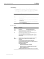
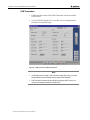
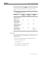
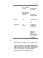
Setting Network Parameters
Configuring MGW x100 for first use requires connecting a PC to Controller
A's COM1 port (front) and the use of HyperTerminal to access MGW x100.
If reconfiguring MGW x100's host controller name, use Telnet to access
MGW x100. To reconfigure TCP/IP settings, use the Platform page in MGW
EMS or the command line interface accessible via Telnet.
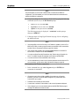
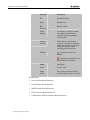
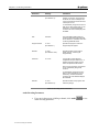
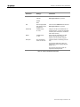
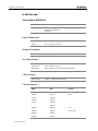
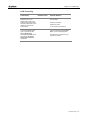
Network Interfaces and Default Settings
The table below lists available network interfaces and default settings. These
default settings apply to the interfaces of Controller A and B (when
applicable).
Name
Interface ID
Alias
IP Address
Subnet Mask
Front Gig1
1
gei5
115.100.100.100
255.255.0.0
Front Gig2
2
gei4
114.100.100.100
255.255.0.0
Rear A
3
gei3
113.100.100.100
255.255.0.0
Rear B
4
gei2
112.100.100.100
255.255.0.0
PMC Ch A (front)
5
gei0
110.100.100.100
255.255.0.0
PMC Ch B (front)
6
gei1
111.100.100.100
255.255.0.0
* Available only in
MGSS5000
configuration
* Available only in
MGSS5500
configuration
Table 7: Default settings for MGW x100's Network Interfaces
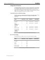
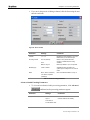
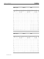
My Network Settings
Use the table below to make a note of your current network settings.
Name
Interface ID
Alias
Front Gig1
1
gei5
Front Gig2
2
gei4
Rear A
3
gei3
Rear B
4
gei2
PMC Ch A (front)
5
gei0
PMC Ch B (front)
6
gei1
IP Address
Subnet Mask
Table 8: My settings for MGW x100's Network Interfaces
48 Configuring MGW x100
Chapter 1 • Configuring MGW x100
Note
To configure and manage MGW x100 via Telnet or MGW EMS, use the IP address
assigned to the NIC labeled Gig. Ethernet B on Controller A's I/O board (rear). Controller A
is installed in slot 7, which is labeled Control A (applicable only to MGWx100).
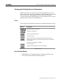
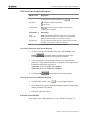
Enabling/Disabling Backup Channels
MGW x100 lets you add hot stand-by (backup) channels, which will take
over automatically if the primary channel fails.
If you do not want hot stand-by channels to take over, you can use the
command line interface to disable the relevant codes.
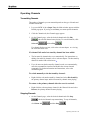
To disable codes:
1. Use Telnet or HyperTerminal to access the command line interface as
explained on the previous pages.
2. At the command prompt, type excludeChFcodes 2010 2014 and press
Enter; the relevant codes are disabled and hot stand-by channels will not
take over when sources become unstable.
3. To preserve this setting, type save excludeChFcodes 2010 2014 and
press Enter; the codes remain disabled after restarting MGW x100.
To restore disabled codes:
1. At the command prompt, type excludeChFcodes 999999 and press
Enter; the relevant codes are restored.
2. To preserve this setting, type save excludeChFcodes 999999 and press
Enter; the relevant codes remain active after restarting MGW x100.
Configuring MGW x100 49
Chapter 1 • Installing Software
Installing Software
You operate MGW x100 from a PC on your network. This PC will be
referred to as Management PC.
To operate MGW x100, you need to install the MGW EMS. Before installing
the MGW EMS, you must configure your PC for the network. If you replace
the Management PC, make sure that the new PC's network settings match the
previous PC's settings. If you choose different settings, the new Management
PC may not be able to communicate with MGW x100.
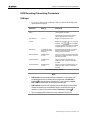
System Requirements
Pentium-III PC 500 MHz or higher with a 10/100BT network interface card
(NIC).
y
The MGW EMS currently supports the following operating systems:
y
Windows 2000 Professional with Service Pack 4
y
Windows XP Professional with Service Pack 1 or higher
y
128 MB RAM or more, depending on the number of MGW x100 units
you manage from the relevant PC.
y
200 MB free disk space or more.
y
CD-ROM drive (16× or faster).
Configuring the Management PC for the Network
Go to My Network Places and then to Local Area Connection.
y
Refer to the relevant Microsoft Windows documentation for further
instructions.
Installing MGW EMS
MGW EMS installs together with the current version of Java Runtime. To
install MGW EMS, follow the instructions below.
1. If you are about to upgrade an existing system, use the previously
installed version of MGW EMS to upgrade the system software before
installing a new version of MGW x100.
2. Close all programs and use the Add/Remove Programs wizard to uninstall
any earlier version of MGW EMS that you may have installed on your
PC.
3. Insert the MGW x100 CD into your PC's CD ROM drive.
50 Installing Software
Chapter 1 • Installing Software
4. On the MGW x100 CD, navigate to the MGW EMS folder; installation
files appear.
5. Double-click MGW_EMS_Setup.exe and follow the on-screen
instructions.
y
You will be asked whether you wish to edit the default IP address
127.0.0.1 specified for MGW EMS. We recommend setting it to the IP
address associated with the MGW unit used most often.
y
You will also be able to define up to eight additional IP addresses for
frequently used units from which you can choose one when logging on.
y
If you are asked whether you want MGW EMS to overwrite an already
installed version of the Java Virtual Engine, choose Yes. If you choose No,
the installation may fail.
6. MGW EMS is installed and a shortcut is added to your Desktop.
7. When you open MGW EMS, the Logon window appears with the default
IP address 127.0.0.1 or with the IP address that you defined, for example
172.16.100.253.
8. If you click the arrow to the right; a list appears with the additional IP
address you defined.
To edit the default IP address at a later stage:
1. Close MGW EMS.
2. Browse the MGW EMS folders for EMSConfig.ini and create a backup.
Save the backup in a different folder on your PC.
3. Browse the MGW EMS>cfg folder and open the EMSConfig.ini; the
first line has the following syntax:
emsx100.snmp.deviceIP <IP address>.
4. Modify the registered IP address to the desired IP address.
5. Save and close EMSConfig.ini; MGW EMS displays the new IP
address once the Logon window appears.
To edit the list of available IP addresses at a later stage:
1. If relevant, close MGW EMS.
2. Browse the MGW EMS\cfg folder. Open the devicesList.ini and create a
backup of the devicesList.ini file. Save the backup in a different folder
on your PC.
3. Open devicesList.ini; the IP addresses you defined appear listed.
4. Modify the listed IP addresses as desired and verify that your updated list
includes the default IP address.
Installing Software 51
Chapter 1 • Installing Software
Note
y
If the available disk space is insufficient, installing MGW EMS will fail.
y
If you want to uninstall MGW EMS after you edited EMSConfig.ini and/or
devicesList.ini, you will have to manually delete the MGW EMS program folder.
y
You can list up to eight IP addresses in devicesList.ini.
MGW EMS - Managing Software Versions
System software versions will be made available for upgrading MGW x100
using MGW EMS. The respective software versions will be available as zip
files for download from Optibase's FTP site or distributed on a CD.
Instructions and required passwords are provided with upgrade release notes
as relevant.
Depending on available disk space, MGW EMS allows you to upload and
store up to three software versions that you can activate when desired. You
can view the Version Definition files (VDF files) of uploaded and activated
software versions in the Version Management window under Available
Versions. The currently active version's VDF file appears under Current
Version. The Version Management window also displays used and available
disk space on the host controller's disk where uploaded software versions are
stored.
To view a list and details of current software versions:
1. Start MGW EMS and log on to MGW x100 as explained in the user
manual.
2. On the toolbar, click SW Version
, the Version Manager
window appears displaying the VDF files of currently uploaded and
active software versions. MGW x100's disk can host up to two additional
software versions besides the default version DEFVER.VDF that cannot
be deleted.
3. Select the desired software version from the list and click Properties
a window appears displaying the selected version's details.
52 Installing Software
Chapter 1 • Installing Software
4. To update the Software Version list, click Refresh
Figure 12 :Software Version Management
To upload a new software version:
1. If not already done, start MGW EMS and log on to MGW x100 as
explained in the user manual.
2. In the Version Manager window, click Add
3.
the File Dialog window appears, displaying zip files and the associated
Version Definition files (*.vdf).
4. If relevant, navigate to the desired software version's location
5. Select the desired zip file and click Add SW Version; the selected
software version uploads with the associated VDF file, which may take
several minutes.
Note
y
If you wish to upgrade or downgrade across several software versions, you have to
upgrade/downgrade stepwise. For example, to upgrade version 3.5 to version 4.5, you
have to first upgrade to version 4.0.2 before you can upgrade to version 4.5.
y
Redundant host controllers must have the same default software version activated.
y
We recommend stopping all channels before activating a software version.
Installing Software 53
Chapter 1 • Installing Software
y
To free disk space, we recommend deleting rarely used software versions and keeping
them available on a PC or server on the network.
To activate a software version:
1. If not already done, start MGW EMS and log on to MGW x100 as
explained in the user manual.
2. Make a note of channels associated with boards affected by activating the
desired software version. Boards associated with certain channels are
listed below.
y
Live encoders. Encoding and transcoding channels will be removed.
y
DVB transcoders. Transcoding channels will be removed.
y
DVB recasters. DVB recaster channels will be removed.
y
DVB transraters. DVB transrater channels will be removed.
y
Switch and/or host controller. All channels are removed and the system
resets.
3. Select the desired software version from the list and click Activate
. the affected boards or the entire unit reset. If the
software version affects the switch, it may take up to 15 minutes until
MGW x100 is ready to operate again.
y
If this software version supports the currently installed version of MGW
EMS, MGW x100 logs on again.
y
If this software version requires a different version of MGW EMS, MGW
x100 remains logged off. In this case, close the currently installed MGW
EMS and refer to the instructions on installing a different version.
Note
y
If you wish to upgrade or downgrade across several software versions, you have to
upgrade/downgrade stepwise. For example, to upgrade version 3.5 to version 4.5, you
have to first upgrade to version 4.0.2 before you can upgrade to version 4.5.
y
Redundant host controllers must have the same default software version activated.
y
We recommend stopping all channels before activating a software version.
y
To free disk space, we recommend deleting rarely used software versions and keeping
them available on a PC or server on the network.
To delete a software version:
1. If not already done, start MGW EMS and log on to MGW x100 as
explained in the user manual.
2. Make sure that the desired version is not active.
. The
3. Select the desired software version and click Del
selected software version is deleted and the associated VDF file removed
from the Available Versions list.
54 Installing Software
Chapter 1 • Installing Software
Note
The default version cannot be deleted.
Installing Software 55
Chapter 2
User Manual
In This Chapter
y
Accessing MGW x100 57
y
Main Window Overview 61
y
Setting SAP (Session Announcement Protocol) 69
y
Setting NTP (Network Time Protocol)
y
Viewing and Setting Service Parameters
y
Creating and Editing a Channel Profile 90
y
Live Encoding Parameters
y
DVB Recasting/Transrating Parameters 127
y
DVB Transcoding Parameters 129
y
Target Parameters
136
y
Version Management
141
y
Operating Channels
143
y
In Case of Problems
144
y
Reports
145
71
104
73
Chapter 2 • Accessing MGW x100
Accessing MGW x100
You manage MGW x100 using MGW EMS, an SNMP based management
application installed on a PC on the network, which allows you to remotely
add, edit and remove service channels associated with installed hardware.
Before starting to operate service channels, you have to log on to the desired
MGW unit.
Users
MGW units ship with three default users configured, each one associated with
a certain user profile. The password for the default users is optibase. You can
add, edit and delete additional users associated with these user profiles. Users
are specific to the unit you are logging on to.
User Profile
User
User Rights
Guest
guest
Views channel parameters and profile
Views the list of users allowed to log on to this unit.
Views the list of users currently logged on to this unit.
Administrator
admin
In addition to the Guest rights:
Sets channel parameters.
Adds and removes channels.
Starts and stops playing channels.
Super User
super
In addition to the Administrator rights:
Adds, edits and removes users allowed to log on to this unit.
Logs off other users.
Restarts this unit.
Table 9: MGW x100 Users
Note
y
User names and passwords may consist of max. 255 ASCII-English characters.
y
Only one Super User or Administrator can log on to MGW x100 at a time. If you try to
log on as Super User or Administrator and there is already a Super User or
Administrator logged on, MGW x100 logs you on as Guest.
y
If MGW EMS fails while Super User or Administrator is logged on, the relevant user
remains listed. In this case, log on again as Super User or Administrator. Although
registered as Guest, you will be able to remove the Super Use or Administrator from
the list.
Accessing MGW x100 57
Chapter 2 • Accessing MGW x100
Working with several Units
Depending on the Management PC's available system resources, you can
open several MGW EMS instances at a time allowing you to manage multiple
MGW units.
To switch to additional units, you may use Re-Login. You can also use ReLogin to switch between MGW 1000, MGW 1100 and MGW x100 units.
Required Memory (MB)
Number of active MGW EMS instances
50
1
100
2
300
6
Table 10: Required Resources for running multiple Instances of MGW EMS
Note
We recommend not opening more than six MGW EMS instances at a time.
Logging on to MGW x100
1. On the Management PC, go to the Start menu and then to MGW EMS;
the Login window appears with the default IP address you defined.
2. When required, enter a different IP address in the respective field and
choose the desired user rights from the Privileges list.
y
To view a list of additional IP addresses you defined for frequently used
units, click the Arrow button to the right.
y
To scan the network for all available units within the Management PC's
workgroup and VLAN, click Discover
y
58 Accessing MGW x100
.
Select the desired unit; the associated unit's IP address appears.
Chapter 2 • Accessing MGW x100
3. Type the user name and password in the respective fields and click OK
; the MGW unit is identified and MGW EMS appears with the
Boards page open. The unit's IP address appears in the Status bar to the
left and the current user level to the right.
Note
Only one Super User or Administrator can log on to a specific MGW unit at a time. If you try
to log on as an additional Super User or Administrator, the relevant unit logs you on as
Guest.
To Use SNMP Community String:
MGW x100 provides a higher level of security using SNMP Community
String.
1. In the Login window click Advanced. An expanded Login window with
Community String appears.
2. In the Community field, enter the required community string.
Note
The community string is registered in the EMSConfig.ini file.
3. To close the expanded login window click Advanced.
4. click OK
.
To check the MGW Unit Status after logging in:
1. Use the following indications:
y
The blue arrow to the upper left
and the green LED in the Status
bar indicate that the MGW unit is responding properly.
Accessing MGW x100 59
Chapter 2 • Accessing MGW x100
y
If the arrow to the upper left is broken and turns red
together
with the LED in the Status bar, The MGW unit has either been switched
off or has stopped responding.
Logging on to a different Unit or as a different User
1. On the toolbar, click Re-Login
; the Login window appears.
2. Enter the unit's IP address or hostname in the respective field and choose
the desired user from the Privileges list.
y
To log on to the same unit as a different user, leave the IP address as is and
choose the desired user from the Privileges list.
3. To learn more about the Main window, refer to the next page.
Viewing a list of permitted Users
y
In the Menu bar, go to Login and then to Users/Permissions Table; the
currently defined users appear.
Viewing a list of current Users
y
In the menu, go to Login and then to Current Users Table; the current
users appear with the IP address of the Management PC or the user group.
This list also displays each user's logon time.
Forcing a User Out
1. In the menu, go to Login and then to Current Users Table; the current
users appear.
2. Select and right-click the desired user and then choose Force Logout; the
associated MGW unit notifies the relevant user that he/she has been
logged off.
Logging Off
y
60 Accessing MGW x100
On the Main window's Title bar, click Exit and confirm your request; the
associated MGW unit logs off and MGW EMS closes.
Chapter 2 • Main Window Overview
Main Window Overview
By default, the MGW EMS Main window appears with the Boards page
open. The Boards page displays currently installed boards and lets you view
or set parameters. The Channels page displays the current channel profile and
lets you add, edit, remove and operate channels.
The Boards Page
Figure 13 :MGW EMS - Boards Page
LEDs
Status
Description
System
Green
Red
MGW 1100 unit is running.
System error.
BIT
Green,
Not used at present.
Gray
Images
Description
Reflects an installed service board with associated LEDs
(front). Information regarding the LED status can be found
in the install guide.
Click to open a window that displays the respective service
board's parameters.
Reflects an installed I/O board (rear).
Click to open a window that displays the respective I/O
board's parameters.
Main Window Overview 61
Chapter 2 • Main Window Overview
Parameters for the host controller and switch I/O boards
cannot be viewed or set using MGW EMS.
Table 11: Boards Page
The Channels Page
y
On the Main window, click the Channels tab; the Channels page appears.
Figure 14 :MGW EMS - Channels Page
Secondary Stream channels appear marked by the secondary stream icon left
to the Channel Name column as shown in the figure below:
Figure 15 :Channel List - Secondary Stream
62 Main Window Overview
Chapter 2 • Main Window Overview
Buttons
Description
Opens the Channel wizard to add a channel.
Opens the Parameter window to edit a selected channel.
Opens the Parameter window to view a selected channel's parameters.
Deletes selected channels.
Saves a selected channel as template.
Selects all channels.
Plays selected channels.
Stops selected channels.
Opens the associated help topic.
Table 12: Channels Page
The Platform Page
y
On the Main window, click the Platform tab; the Platform page appears.
Figure 16 :MGW EMS - Platform Page
Main Window Overview 63
Chapter 2 • Main Window Overview
Unit Parameters
y
To change the date, time, name and contact/location information, use
MGW x100's command line interface. For instructions on changing the
relevant parameters, refer to MGW x100's installation guide.
Options
Description
Description
MGW x100's version.
Up Time
The time since system started.
Date
The current time and date.
Name
MGW x100's hostname. To change MGW x100's host name, refer to the
installation guide.
Contact
Contact person (optional). To set or change this information, refer to the
installation guide.
Location
The unit's physical location (optional). To set or change this information,
refer to the installation guide.
Table 13: Unit Parameters
Interface Table
Options
Description
Status
Disconnected
Connected
Name
Displays the interface name in accordance to the interface physical
characteristics and its position on the host board
I/F
Each interface is associated with a number that identifies its type and
location on the respective host controller unit.
No network segment connected
Network segment connected
This number appears also in the Output Interface window on the UDP
Target page if you select the output interface manually as required for
Multicast targets.
Slot
Displays the slot in which the respective host controller unit is installed.
Redundancy
Mode
Allows you to set and configure the network redundancy mode for each
interface. Changes are made for Host A and reflected on Host B
automatically.
To configure network redundancy perform the following steps:
Click the appropriate interface in the Redundancy Mode column. The Set
Redundancy for I/F window appears.
Set the following parameters:
y
Redundancy Status (Protected or Standalone)
y
Redundant I/F - only if Protected was selected, select the appropriate
interface for redundancy. The Redundancy Mode for the backup
interface is updated automatically.
This table describes the displayed redundancy modes for both the primary
and backup interfaces:
64 Main Window Overview
Chapter 2 • Main Window Overview
IP Address
Displays the respective network interface's IP address and subnet mask
respectively. Instructions on changing the IP address and the subnet mask
can be found below.
Subnet Mask
Displays the respective network interface's subnet mask.
Utilization
Specified the how much bandwidth is used out of the total bandwidth.
Usage
Specifies the usage of the interface - Stream or Management
Table 14: Interface Table
Note
y
Do not use the NICs on the host controller I/O board(s) for the output as this will
disrupt the communication between MGW EMS and the MGW unit.
y
Depending on purchased capabilities, DVB recasters and DVB transraters can transmit
via a separate NIC on the relevant I/O board, thus providing additional bandwidth of 60
Mbps per DVB recaster/transrater..
y
If you use a host controller without the optional PMC module, interfaces #5 and #6 are
not assigned.
Editing Interface Parameters
Every interface has a default IP address and a subnet mask assigned,
which can be found in the installation guide.
If you have Host B and Switch B installed as a backup (applicable to MGW
5100 only), make sure to assign the network interface for the management on
Host B to the same subnet, otherwise MGW EMS will be unable to switch
over to Host B in case Host A and/or Switch A fail.
In case Host B and Switch B take over, the IP addresses and subnet masks for
the output interfaces on Host B are updated automatically.
To assign new interface parameters:
1. Before changing a network interface's IP address or subnet mask, stop all
channels.
2. On the Platform page, double-click the desired parameter; the desired
parameter becomes available for editing.
Main Window Overview 65
Chapter 2 • Main Window Overview
3. Enter the desired parameter and click Apply
parameter is changed.
; the desired
4. If you change a network interface's IP address or the subnet mask, you
will be asked if you want to restart MGW x100. Restarting MGW x100 is
recommended but not required.
You can import network settings from different MGW x100 units.
Setting Network Interface Redundancy
If network interface redundancy is required, any NIC used for streaming can
be set as a backup so when the primary NIC fails, the assigned backup NIC
takes over.
To assign a backup network interface:
1. On the Platform page, select the appropriate interface to be backed up by
clicking the Standalone button in the Redundancy Mode column. The Set
Redundancy I/F… window is displayed.
Figure 17 :Set Redundancy for I/F window
2. From the drop-down menu in the Redundancy Status select Protected.
3. From the drop-down menu in the Redundant I/F select the appropriate
interface to be the backup and click OK.
4. On the Platform page click Apply.
Note
66 Main Window Overview
y
Ensure to click Apply otherwise new settings will not apply.
y
Management NIC cannot be used for redundancy.
y
When a streaming NIC (that has playing channels) is set as a backup NIC for another
streaming NIC, these playing channels will be automatically passed over to the
protected NIC. Ensure that the combined streaming bandwidth is within the NIC
bandwidth limit.
Chapter 2 • Main Window Overview
Recovery from a NIC Failure
When two NICs are in a redundancy mode and the protected NIC fails (shows
as Disconnected) the followings will occur:
y
The playing channels of the protected NIC will be automatically passed
over to the standby NIC.
y
The Redundancy Mode of the backed up NIC will be changed from
Protected to Inactive Protected.
y
The Redundancy Mode of the standby NIC will be changed from Standby
to Active Standby.
The following are few of the options available for recovery after the
connection problem was fixed:
y
Remaining in a Inactive Protected /Active Standby NIC states. The
currently inactive NIC functions as the backup NIC.
y
Restoring to the original redundancy state by clicking on the Inactive
Protected button and in the Set Redundancy I/F… window click
Restore.
Tools
Options
Description
Applies changes. This button is disabled if you are logged on as Guest.
Updates parameters that have changed while the Platform page was open.
Restarts MGW x100. It will take several minutes until MGW x100 finishes
booting and logs you back on. This button is disabled if you are logged on as
Guest.
Table 15: Tools
Main Window Overview 67
Chapter 2 • Main Window Overview
Buttons and Displays
The Main window's Menu and Status bars are available from all pages :
Boards, Channels and Platform. The following table explains available
options.
Options
Description
Opens the Login window to log on to a different unit or as a
different user.
Opens the Configuration Manager, which lets you save, and
load a channel profile associated with a certain board profile.
Opens the Channel wizard and lets you add a channel.
Opens the Software Version manager, which lets you add,
activate and remove software versions.
Opens the Template manager, which lets you view, add and
remove channel templates.
Maximizes the Main window.
Increases the Main window.
Decreases the Main window. To minimize the Main window,
use the Minimize button in the Title bar to the right.
Opens the MGW EMS help. The MGW EMS help requires an
Internet browser and has been optimized for Internet Explorer
5.x and higher.
Displays a list of open alarms associated with the respective
level of severity.
Displays
Description
MGW x100 is responding properly.
MGW x100 has been switched off or is not responding.
The IP address of the MGW x100 unit that you are logged on
to.
Current user profile.
Table 16: Tool Bar, Status Buttons and Displays
68 Main Window Overview
Chapter 2 • Setting SAP (Session Announcement Protocol)
Setting SAP (Session Announcement Protocol)
By default, SAP is enabled for the channel but disabled as per the system
level (see figure below).
Figure 18 :Enabling SAP for a Channel
In order to implement SAP services, perform the following steps:
1. From the main menu select Tools>SAP Parameters. The SAP Parameters
window appears.
Figure 19 :SAP Parameters window
Setting SAP (Session Announcement Protocol) 69
Chapter 2 • Setting SAP (Session Announcement Protocol)
2. Select the System SAP Enabled check box.
3. If required, modify the following default parameters: Target IP, Target
Port, TTL, Interval.
4. Click Apply. This will enable SAP for all SAP enabled channels.
Note
y
To disable SAP services (for all enabled SAP channels) clear the System SAP
Enabled check box and click Apply.
y
To enable or disable SAP services for a specific channel click Edit on the Channels
page and select or clear the SAP check box.
70 Setting SAP (Session Announcement Protocol)
Chapter 2 • Setting NTP (Network Time Protocol)
Setting NTP (Network Time Protocol)
In order to configure NTP services, perform the following steps:
1. From the main menu select Tools>NTP. The NTP Parameters window
appears.
Figure 20 :NTP Parameters
2. Select the System NTP Enabled check box.
3. If required, set the following default parameters: Server IP, Time Zone,
and Sync Period.
Note
In the Sync Period field you set the time in which the Host will be synchronized with the
NTP server.
All service boards are synchronized with the Host every minute regardless what is set in the
Sync Period field.
4. If required select the Daylight Saving check box and set the Start Date
and the End Date and Hour.
5. Click Apply. This will enable NTP functionality.
The Status field indicates:
y
Synchronized - when synchronization is successful
Setting NTP (Network Time Protocol) 71
Chapter 2 • Setting NTP (Network Time Protocol)
y
Error - when synchronization fails
Note
To disable NTP clear the System NTP Enabled check box and click Apply.
72 Setting NTP (Network Time Protocol)
Chapter 2 • Viewing and Setting Service Parameters
Viewing and Setting Service Parameters
MGW x100 consists of a chassis with service units installed. These service
units consist of service and corresponding I/O boards installed at the front and
the rear respectively. Board parameters can be viewed by clicking the
relevant board's image on the Boards page. Tools available from every board
parameter page are listed and explained below.
Tools
This section lists and explains tools that appear with board parameter screens.
Buttons
Description
Updates the displayed parameters.
Closes the current window.
Opens the associated help topic.
Not used at present.
Resets service boards; channels associated with the relevant service
boards will be removed. If you reset Host A or the switch, the entire MGW
x100 unit resets.
This option is not available for I/O boards.
Not used at present.
Displays the board's details, such as version and state.
Table 17: Tools
Host Controller Boards
y
MGW EMS lets you change parameters of the host controller service
board, but not host controller I/O board parameters.
Viewing and Setting Service Parameters 73
Chapter 2 • Viewing and Setting Service Parameters
y
To access the host controller service board's parameters, click the relevant
service board's image (front).
Figure 21
:Host A Board Parameters
Options
Description
Enable ATM
= ATM unavailable
Enable OAM
= Disabled, ATM unavailable
ATM Physical Framing
Not used.
ATM Mux Type
Not used.
Enable Multi-Unicast
= Enabled
= Disabled
Display Fields
Description
Flash Memory Size
Total disk space.
Flash Memory Free Size
Available disk space.
Table 18: Host Controller Service Board Parameters
74 Viewing and Setting Service Parameters
Chapter 2 • Viewing and Setting Service Parameters
Switch Boards
y
MGW EMS does not let you view or change Switch board parameters.
Figure 22 :Switch Board Parameters
Encoders
y
MGW x100 supports H.264 and MPEG encoders. The encoder service
boards are referred to as MGES-5610 and MGES-5200 respectively.
y
To access encoder service board parameters, click the associated image.
Viewing and Setting Service Parameters 75
Chapter 2 • Viewing and Setting Service Parameters
H.264 Encoder Service Boards
Figure 23 :H.264 Encoder Service Board Parameters
Capabilities
Enable Baseline Profile
Comments
= Encoding using the H264@BL microcode enabled.
= Encoding using the H264@BL microcode disabled.
Enable Main Profile
= Encoding using the H264@MP microcode enabled.
= Encoding using the H264@MP microcode disabled.
Enable AAC Plus
= AAC+ encoding enabled.
= AAC and MPEG-1 Layer 2 encoding enabled.
Enable HDTV
= Encoding using the H264@HP enabled.
= Encoding using the H264@HP disabled.
Enable Dolby Audio
= Dolby encoding enabled.
= Dolby encoding disabled.
Enable Transport
Muxing
= Muxing of transport streams enabled.
= Muxing of transport streams disabled.
Enable RTP Split
Stream
= Encoding separate RTP video and audio streams enabled.
= Encoding RTP streams disabled.
76 Viewing and Setting Service Parameters
Chapter 2 • Viewing and Setting Service Parameters
Enable Multi Audio
= Encoding two stereo channels per video channel enabled.
= Encoding one stereo channel or two mono channels.
Enable Transcoding
= H.264 Transcoding available.
= H.264 Transcoding unavailable.
Lists
Description
Encoder State
FREE: The input is available and a channel can be added.
STOP: A channel is added, but currently not transmitting.
PLAY: A channel is added and currently transmitting.
Resolutions
= Resolution enabled.
= Resolution disabled.
Table 19: H.264 Encoder Service Board Parameters
MPEG Encoder Service Boards
Figure 24 :MPEG Encoder Service Board Parameters
Capabilities
Enable [Format]
Comments
= Enabled.
= Disabled.
Enable Pre-Processing
= Pre-processing filters (e.g. de-interlacing) enabled.
= Pre-processing filters disabled.
Viewing and Setting Service Parameters 77
Chapter 2 • Viewing and Setting Service Parameters
Enable Multi-Audio
= You can encode up to two audio channels per video
channel.
= You can encode only one audio channel per video channel.
Enable Digital I/O
= Encodes analog or digital input.
= Encodes analog input only.
Enable 15M Video
= Video encoding bit-rates above 10 Mbps are unavailable.
= Video encoding bit-rates up to 15 Mbps are available.
Lists
Description
Encoder State
FREE:
The input is available and a channel can be added.
STOP: A channel is added, but currently not transmitting.
PLAY: A channel is added and currently transmitting.
Resolutions
= Resolution enabled.
= Resolution disabled.
Table 20: MPEG Encoder Service Board Parameters
Note
If both Video 1 and Video 2 display Play or Stop, you cannot add an additional channel
associated with the respective encoder.
Encoder I/O Boards
y
Encoder I/O boards are available for analog and digital input and are
referred to as MGEI-5210A and MGEI-5210D respectively.
y
To display the desired I/O board parameters, click the associated image.
y
To display input parameters for a certain video or audio input, choose the
relevant input from the Input tree to the left.
78 Viewing and Setting Service Parameters
Chapter 2 • Viewing and Setting Service Parameters
Analog Video Input
Figure 25 :Analog Video Input Parameters
Parameters
Settings
Comments
Interface Status
Not in Use
Channel stopped or no channel.
In Use
Channel assigned and playing.
No video source.
Input Detect
Video source detected.
Source
Composite
Analog video signal that combines all the
components in one signal.
S-Video
Analog video signal that carries separate
luminance and chroma signals.
Color System
NTSC, PAL,
SECAM, Auto
Detect
Determines the color system. MGW x100
and your source device must be set to the
same color system parameter. If you
choose Auto Detect, MGW x100
automatically detects the correct color
system (except SECAM which has to be
set manually).
Color System Detect
NTSC, PAL,
SECAM
If you choose Auto Detect, this field
displays either NTSC or PAL accordingly.
SECAM must be set manually.
If the color system could not be recognized
or you chose the wrong color system, this
field displays N/A.
Pattern Generation
Optibase Color Bar
If you choose a test pattern while
transmitting a stream, the receiver receives
Viewing and Setting Service Parameters 79
Chapter 2 • Viewing and Setting Service Parameters
Parameters
Settings
Comments
the test pattern when no encoded content
is available.
Force Test Pattern
Check this option if
you wish to
transmit a test
pattern instead of
the encoded
content.
This option enables you to 'blend out' a
section of the received content.
De-Interlacing Filter
To convert input
from interlaced to
progressive frames,
check the
associated check
box.
Available for sources connected to the
video input interfaces labeled A applicable only in MPEG-2 encoding.
Contrast
0 - 255
(the default is 128)
Adjusts the polarity between white and
black in the video signal. If white is very
distant from black, a signal has high
contrast. If white is closer to black, a signal
has low contrast causing it to appear with a
gray tone. Adjusting the contrast changes
the relation between the color steps.
Hue
0 - 255
(the default is 128)
Available for NTSC compliant inputs.
Brightness
0 - 255
(the default is 128)
Adjusts the amount of light emitted in the
video signal.
Saturation
0 - 255
(the default is 128)
Adjusts the amount of color in the signal.
We recommend using this option for
MPEG-2 streams at bit-rates lower than
3200000 bps.
Adjusts the wavelength of the base colors
(i.e. red, green, yellow) in a video signal.
Adjusting the hue creates linear change in
the phase of all the colors.
Table 21: Video Input Parameters
80 Viewing and Setting Service Parameters
y
MGW x100 does not support SECAM sources.
y
Pre-processing filters are available if Pre-Processing is
on the associated Encoding Board Parameter
enabled
page.
Chapter 2 • Viewing and Setting Service Parameters
Advanced Video Input Parameters
y
To view and set advanced input parameters for Composite and S-Video
; a window appears displaying
inputs, click Advanced
additional video input parameters.
Figure 26 :Analog Video Input > Advanced
y
To change and save advanced input parameters, click OK
y
To close the Advanced Input Parameter window without making changes,
click Cancel
.
.
Viewing and Setting Service Parameters 81
Chapter 2 • Viewing and Setting Service Parameters
Parameter
Settings
Comments
Horizontal Offset
(- 32) - (0) pixels
(the default is 0)
A negative horizontal offset value moves the
screen to the left and a positive value moves
it to the right. Changes you apply appear in
the encoded content only.
Vertical Offset
(-16) - (16) pixels
(the default is 0)
A negative horizontal offset value moves the
screen down and a positive value moves it up.
Sharpness Filter
Level 0 - 15
(the default is Level 6)
Filters high frequencies in the picture's blackand-white portion out to obtain a sharper
picture.
Luma/Chroma
Filter
Level 0L - 7L and
Level 0H - 7H
(the default is Level 6L)
Chrominance Low Pass filter for Composite.
Vertical Filter
Level 1 - 7
(the default is 0)
Smoothes the picture by averaging two
adjacent horizontal lines.
Black & White
Filter
Check this option when
transmitting black and
white.
This option eliminates color effects in black
and white streams.
NTSC-J Support
Check this option when
encoding a Japanese
NTSC source.
Accounts for different black values in
Japanese NTSC sources.
Luminance Notch filter for S-Video.
Table 22: Advanced Video Input Parameters
Note
Pre-processing filters are available if Pre-Processing is enabled
Encoding Board Parameter page.
on the associated
Analog Audio Input Parameters
y
MGW x100 does not support advanced audio parameters.
Parameter
Settings
Comments
Interface Status
Not in Use
Channel stopped or no channel.
In Use
Channel assigned and playing.
No audio source.
Input Detect
Audio source detected.
Source
Unbalanced (default)
Balanced
Embedded Audio
Pair
N/A
Not used for analog video inputs.
Sample Rate
32KHz, 44.1KHz,
48KHz
Determines how many samples of analog
audio are collected per second while
capturing the audio stream. This parameter
affects the audio quality.
Tone Generation
Off
Not available.
Table 23: Basic Audio Input Parameters
82 Viewing and Setting Service Parameters
Chapter 2 • Viewing and Setting Service Parameters
Digital Video Input
y
If you click an Encoder I/O board image, video input parameters appear.
Advanced parameters are not available.
Figure 27 :Digital Video Input Parameters
Parameters
Settings
Comments
Interface Status
Not in Use
Channel stopped or no channel.
In Use
Channel assigned and playing.
SDI
SDI compliant digital video signal.
No video source.
Input Detect
Video source detected.
Source
SDI
SDI compliant digital video signal.
Color System
525, 625, Auto Detect
Determines the color system. MGW x100 and
your source device must be set to the same
color system parameter. If you choose Auto
Detect, MGW x100 automatically detects the
correct color system.
Color System
Detect
525, 625
If you choose Auto Detect, this field displays the
correct color system.
If the color system could not be recognized or
you chose the wrong color system, this field
displays N/A.
Pattern
Generation
Black,
Optibase Color Bar
If you choose a test pattern while transmitting a
stream, the receiver receives the test pattern
Viewing and Setting Service Parameters 83
Chapter 2 • Viewing and Setting Service Parameters
Parameters
Force Test
Pattern
Settings
Comments
(default)
when no encoded content is available.
Check to transmit a
test pattern instead of
the encoded content.
This option enables you to 'blend out' a section
of the received content.
Table 24: Video Input Parameters
Digital Audio Input Parameters
y
Verify that the corresponding encoder service board can encode digital
input. In the board parameter page, Digital I/O must be enabled .
Parameter
Settings
Comments
Interface in Use
Not in Use
Channel stopped or no channel.
In Use
Channel assigned and transmitting.
No audio source.
Input Detect
Audio source detected.
Source
AES/EBU
Embedded 1
Embedded Audio
Pair
Available audio
streams, embedded in
the SDI input.
Up to 16 audio streams can be embedded per
SDI input of which you can select two.
Parameters are set automatically.
This field is available if you selected
Embedded under Source Type.
Sample Rate
32KHz, 44.1KHz,
48KHz
Determines how many samples of analog
audio are collected per second while
capturing the audio stream. This parameter
affects the audio quality.
This field is not available for editing if
choosing Embedded under Source Type.
Tone Generation
Off
Not available.
Detect Sample
Rate
Displays the sample
rate at which the source
has been composed.
If using embedded audio or AES3 (AES/BEU)
sources, this field displays the audio sample
rate at which the source was composed.
Table 25: Basic Audio Input Parameters
DVB Recasters and DVB Transraters
y
DVB transraters and DVB recasters use the same DVB I/O board.
y
To view board parameter pages, click the relevant image. DVB recaster
service boards are referred to as MGRS-5200 and DVB transrater service
boards are referred to as MGTR-5200.
DVB Recaster and DVB Transrater Service Boards
y
You can specify and change the IP address and the subnet mask for the
NIC labeled 10/100 BT 1 on a specific DVB I/O board at the rear. This
84 Viewing and Setting Service Parameters
Chapter 2 • Viewing and Setting Service Parameters
NIC is referred to as Rear Port in the service board's parameter page and
used for direct streaming.
y
To assign a generic IP address and a subnet mask to all rear ports in a
specific unit, in the menu, go to Configuration and choose Assign Rear
Port IP; the Rear Port Parameters window appears and you can enter a
generic IP address and a subnet mask.
y
IP address. Enter a generic IP address, for example 172.69.195.1; the
slot number of each DVB transrater or DVB recaster will be added to the
IP address making each IP address unique. For example, if a DVB
transrater or DVB recaster is installed in slot 13, the rear associated port
has the IP address 172.69.195.14 assigned.
y
Subnet mask. The subnet mask you enter will be the same for all rear
ports associated with DVB recasters and DVB transrater in the relevant
unit.
Figure 28 :DVB Recaster/Transrater Service Board Parameters
Rear Port Settings
Description
Specify IP Address
Assign an IP address to the NIC labeled 10/100BT 1 on the DVB I/O
board.
If an IP address is assigned, it appears under Current IP Address.
If no IP address is assigned, 0.0.0.0 appears.
Specify Subnet Mask
Assign a subnet mask to the NIC labeled 10/100BT 1 on the DVB I/O
board.
If a subnet mask is assigned, it appears under Current Subnet Mask.
If no subnet mask is assigned, 0.0.0.0 appears.
Viewing and Setting Service Parameters 85
Chapter 2 • Viewing and Setting Service Parameters
Rear Port Settings
Description
Capabilities
Description
Enable 4 ASI Inputs
Enable Full BR
= All four DVB-ASI input interfaces can connect to DVB sources.
Always enabled.
= An accumulated bit-rate of 60 Mbps can be transmitted.
= An accumulated bit-rate of 40 Mbps can be transmitted.
Enable Transrating
= Enabled, if you have a DVB Transrater Service board installed.
= Disabled, if you have a DVB Recaster Service board installed.
Enable Rear
Streaming
= 10/100BT 1 on the DVB I/O board is connected to a network.
= No network segment connected.
Table 26: DVB Recaster/Transrater Service Board Parameters
Note
y
To avoid internal network conflicts, do not assign IP addresses to the rear ports that
start with 180.100.*.* or 190.100.*.*.
y
If you assign or change IP addresses or subnet masks for the rear port, you have to
reset every affected DVB recaster and/or transrater service board.
86 Viewing and Setting Service Parameters
Chapter 2 • Viewing and Setting Service Parameters
DVB I/O Boards
y
To access the DVB I/O board's parameters, click the desired board's
image.
Figure 29 :DVB I/O Board Parameters
Parameters
Description
Monitor Interface
Enter the DVB input that you wish to preview while recasting.
Signal Detected
= DVB-ASI compliant source detected.
= No source.
Available Programs
To view a list of available programs, click
.
Table 27: DVB I/O Board Parameters
Viewing and Setting Service Parameters 87
Chapter 2 • Viewing and Setting Service Parameters
DVB Transcoders
y
DVB transcoders consist of the DVB Transcoder I/O and an encoder
service board.
y
To access DVB Transcoder I/O or encoder service board parameters,
click the relevant board image.
Figure 30
:DVB Transcoder I/O Board Parameters
Note
y
If Video State under Transcoder 1 and Transcoder 2 display Play or Stop, you cannot
add an additional channel associated with the respective DVB transcoder.
y
DVB Transcoder I/O boards with one DVB-ASI input interface (ASI I/F) and a Loop
connector are available and referred to as MGTI-5210.
88 Viewing and Setting Service Parameters
Chapter 2 • Viewing and Setting Service Parameters
DVB Transcoder I/O Board Parameters
ASI I/F 1 and 2
Description
Programs View
To view a list of transmitting programs, click
Input Detect
.
= DVB-ASI compliant input detected.
= No source.
Interface Status
Not in Use: A source might be connected, but no channel is
configured.
In Use: Channel configured.
Transcoder 1, 2
Description
Video,
Audio 1 and 2
FREE: Input available; a DVB transcoding channel can be added.
STOP: A DVB transcoding channel is added, but not transmitting.
PLAY: A DVB transcoding channel is added and playing.
Original Source
Lets you preview the original source of a certain program. For further
information and instructions, refer to the next page.
Table 28: DVB Transcoder I/O Board Parameters
Previewing Sources for the Current Program
1. On the Transcoder I/O board Parameter page, under Sources, click
Details
; the Details window appears displaying source
parameters associated with the currently active program.
2. Verify that monitors are connected to the relevant video and audio
connectors. These monitors must have a Composite Video input and an
Unbalanced Audio input respectively.
Transcoder 1 refers to Video A and Audio A.
Transcoder 2 refers to Video B and Audio B.
3. Click Preview
; the associated stream starts playing.
Previewing Sources for a Different Program
1. On the Details window, click
; a list of programs appears.
2. Select the desired program; the Program number appears under program
and the parameters are updated.
3. Follow the instructions above.
Encoder Service Boards
For Encoder Service Board parameters, refer to Encoders (on page 75).
Viewing and Setting Service Parameters 89
Chapter 2 • Creating and Editing a Channel Profile
Creating and Editing a Channel Profile
The number of channels you can add depends on the type of boards and
available input interfaces.
Adding Channels
The number of channels you can add depends on the type of boards installed
and available input interfaces. To add channels, use the Channel wizard,
which guides you through the process. The Channel wizard consists of three
steps:
1. Defining a channel. Use previous configurations that you saved as
templates or manually configure a new channel. You can also back up
existing (primary) channels.
2. Choosing channel components. Choose a service unit, an input interface
and a target that support the channel you defined.
3. Setting channel parameters. Set Input, processing and target
parameters.
MGW x100 supports the following channel types:
y
Live Encoding H.264
y
Live Encoding MPEG-1/2
y
DVB to IP Recasting. For further details refer to DVB Recasting.
y
DVB to IP Transrating. For further details refer to DVB Transrating.
y
DVB to IP Transcoding. For further details refer to DVB Transcoding
MPEG-1/2 or DVB Transcoding H.264.
90 Creating and Editing a Channel Profile
Chapter 2 • Creating and Editing a Channel Profile
Defining a Channel
1. On the Main window, in the toolbar, click Add Channels
the Channel wizard appears.
;
Figure 31 :Adding a Channel - Step 1, Channel Options
2. Select a channel name (e.g. Test 2) by overwriting the default in the
Channel Name field to the upper left. Every channel must have a different
name. Channel names may consist of up to 255 ASCII-English
characters.
y
If you try to use a name that has already been assigned to a different
channel, you receive an error message.
y
If you add a hot stand-by channel, the channel name appears with the
extension StandBy. Do not change the hot stand-by channel's name.
1. Choose one of the three channel options listed below:
y
From Template. Choose the desired template from the list.
y
From Type. Choose a channel type with default input and output
parameters. Available channel types are listed in the previous page.
y
Hot Stand-by. Choose the channel from the list that you wish to back up.
Creating and Editing a Channel Profile 91
Chapter 2 • Creating and Editing a Channel Profile
1. Click Next
; lists appear for the relevant input, processing and
output components (targets). Input and processing components refer to
available I/O and service boards.
Make sure not to assign primary and hot stand-by channels to the same
boards.
Choosing Channel Components
For Live Encoding:
y
Input Component. Select an MPEG Encoder I/O board from the list.
Only Encoder I/O boards with at least one available input interface
appear.
y
Process Component. Displays the service board that corresponds to the
selected I/O board.
y
Output Component for H.264 and MPEG-1/2. MGW x100 supports
up to 8 UDP targets per host controller unit for each encoded stream.
To add a target, select the desired option and click Add
.
For DVB Recasting:
y
Input Component. Select a DVB I/O board from the list.
y
Output Component. MGW x100 supports up to 8 UDP targets per
filtered and/or converted IP stream. To add a target, select the desired
option and click Add
.
For DVB Transrating:
y
Input Component. Select a DVB I/O board from the list.
y
Process Component. Displays the service board that corresponds to the
selected I/O board.
y
Output Component. MGW x100 supports up to 8 UDP targets per
filtered and/or converted IP stream. To add a target, select the desired
option and click Add
.
Note
y
Make sure to keep at least one output component (target) assigned; otherwise you
cannot complete the Channel wizard.
y
You cannot add or remove targets once you quit the Channel wizard. If you wish to add
or remove targets at a later stage, delete the relevant channel and add it again with the
desired targets.
y
Make sure to assign primary channels and hot stand-by channels to different boards.
92 Creating and Editing a Channel Profile
Chapter 2 • Creating and Editing a Channel Profile
y
If you add a hot stand-by channel to a DVB transcoding or a live encoding channel,
associated with an SDI source, connect the relevant source to a separate input
interface and not to the primary channel's I/O board's Loop connector.
Transcoder I/O boards are available with two DVB-ASI inputs or one DVB-ASI input
and one Loop connector.
For DVB Transcoding:
y
Input Component. Select a DVB I/O board from the list. DVB I/O
boards only appear in the list if a DVB Transcoder channel can be added.
Note
If the DVB Trancoding H264 option does not appear in the Channel Type drop down list,
ensure that the appropriate type was defined as described in Adding Channels (on page
90).
y
Process Component. Displays the service board for re-encoding that
corresponds to the selected I/O board.
y
Output Component MGW x100 supports up to 8 UDP targets per host
controller unit for each encoded stream. To add a target, select the desired
option and click Add
.
Setting Channel Parameters
y
After setting input, processing and output components (targets), click
; channel parameters appear. Follow the instructions
Next
below to set or change channel parameters.
If you added a Hot Stand-By Channel
y
Do not change channel parameters or targets if you are adding a hot
stand-by channel. Channel parameters and targets are synchronized with
the associated primary channel's parameters and targets.
SAP Service
By default the SAP check box is selected. To disable SAP service clear the
check box.
Input Parameters
y
Live Encoding. On the Parameters page, click IO Parameters
; input parameters appear and can be set or changed.
y
DVB Recasting and DVB Transrating. On the Parameters page, in the
IP Input I/F section, under Programs, click
; programs received
by the selected DVB-ASI Input interface are available and parameters can
be set or changed.
Creating and Editing a Channel Profile 93
Chapter 2 • Creating and Editing a Channel Profile
y
DVB Transcoding. On the Parameters page, in the IP Input I/F section,
under Program, click
; programs received by the selected DVBASI Input interface are available.
Processing Parameters
y
If you are adding an encoding or transcoding channel, set or change
processing (encoding) parameters as required. For processing (encoding)
parameters, refer to Encoding Parameters (on page 104).
Target Parameters
y
Select the relevant target and click Edit
appear and can be set or changed.
y
To add different targets, click Back
targets.
; target parameters
and add the desired
Note
You cannot add or remove targets once you quit the Channel wizard. To add or remove
targets at a later stage, remove the relevant channel and add it again with the desired
targets.
Completing the Channel Wizard
y
When finished, click Apply
; the Channel wizard closes and
the channel appears in the list with the new parameters set.
y
Hot stand-by channels appear below their primary channels as shown
below.
Figure 32 :Channels with associated Hot Stand-by Channel
Saving the new Channel as a Template
y
In the Channels list, select the new channel, click Save
and
assign a name to the respective template; the channel is saved and
available as a template.
94 Creating and Editing a Channel Profile
Chapter 2 • Creating and Editing a Channel Profile
Viewing Channels
To view the Channels list:
y
On the Main window, click the Channels tab; the Channels list appears.
The Channels list displays the following details:
y
Channel Name. Displays the channel name and provides indication of
SAP status. you assigned when adding the channel.
Three configuration options are available:
- Sap is enabled in both channel and system.
- Sap is enabled only for the channel.
No SAP is configured for the channel.
y
Service. Displays the channel type.
y
Program. Displays the program number(not relevant to live channels).
y
V.PID (Video PID).Displays the V.PID # (relevant only to transcoder
channels).
y
Input. Depending on the I/O board, it displays the input type.
y
Slot/IF. Displays the slot number and the associated video input
interface.
y
State. Displays the channel state as listed below.
State
Error
Status
What it means
Stopped
(orange)
Channel
OK
The channel is ready.
Playing
(green)
Channel
OK
The channel is playing.
Stopped
Error
The channel encountered an error while playing, possibly
caused by unsupported parameters that you may have set. The
channel cannot restart until this error has been resolved.
Error
The channel encountered an error, but continues playing.
Error
The channel encountered an error, possibly caused by setting
unsupported parameters. The channel cannot start until the error
has been resolved.
N/A
The channel is being established.
(orange)
Playing
(green)
Not Ready
(red)
Processing
(purple)
Creating and Editing a Channel Profile 95
Chapter 2 • Creating and Editing a Channel Profile
Table 29: Channel States
y
Target IP: Port. Displays the channel's target IP address and its port.
y
Output IF. Displays the output stream Interface name.
y
BW (Kbps). Displays the bandwidth of the channel in Kbps.
To save a channel as template:
y
Select the desired channel and click Save
and appears listed in the Template Manager.
; the channel is saved
To delete a channel:
1. Stop the desired channel.
2. Select the desired channel and click Del
deleted.
; the relevant channel is
To toggle the order of channels displayed in the Channels list:
y
By default, the channels appear in descending order with the last-added
channel at the bottom.
y
To sort the channels according to a certain channel detail (e.g. Service),
click the header of the desired column; an arrow
appears, and the
channels are sorted as desired, in ascending order.
y
To toggle the order, click
; the channels appear in descending order
and the arrow toggles to .
To sort the Channel Name and State columns:
y
Click the Channel Name column header and select By Name or By Sap.
The sort order changes accordingly.
y
Click the State column header and select By State or By Error. The sort
order changes accordingly.
To view a channel error:
1. Select and right-click the desired channel.
2. From the shortcut menu, choose Show Error; the relevant error message
appears
-Or Place the mouse cursor on the State field. A tool tip, indicating the error
message, appears.
96 Creating and Editing a Channel Profile
Chapter 2 • Creating and Editing a Channel Profile
For a list of error messages and explanations, refer to the MGW EMS
help.
Editing Channels
To view channel parameters without editing:
y
Select the desired channel and click View
appear but are unavailable for editing.
; channel parameters
To edit channel parameters:
1. If the desired channel is in a Playing state, click Stop
2. Click Edit
;
; channel parameters appear.
3. Click the relevant tabs, set the desired parameters and click Apply
; the new parameters are set.
If you want to save the channel as a template:
y
In the Channels list, select the new channel, click Save
and
assign a name to the respective template; the channel is saved and
available as a template.
To adjust parameters on the fly (while playing the channel):
y
Only encoding or transcoding channels can be edited on the fly.
y
Select the desired channel and click Edit
; The relevant
parameters are displayed. Make sure to adjust in small steps.
Removing Channels
y
Make sure that the relevant channels are stopped.
y
Select the relevant channels and click Delete
; the selected
channels are removed. Templates based on the relevant channels remain
available.
To remove all channels, click Select All
and then Delete
; all channels are removed.
Note
Creating and Editing a Channel Profile 97
Chapter 2 • Creating and Editing a Channel Profile
Template names may consist of max. 255 ASCII-English characters.
Managing Templates
To add a template to the list, you must have at least one channel in the
Channels list (d:\program
files\optibase\mgw5100ems\help\adding_a_channel.htm). You can add a
template either by using the Template manager or from the Channels list.
To open the Template manager and view existing templates:
y
On the toolbar, click Templates
appears displaying existing templates.
; the Template manager
To add a template by using the Template manager:
1. On the Template manager, click Add
displaying existing channels.
; a window appears
2. Select the desired channel and click Apply
added to the list.
; the template is
To add a template from the Channels list:
1. On the Channels list, select the desired channel and click Save
;
you will be asked to assign a name and add a short description (optional).
2. Assign a name and add a description and click Apply
template is added to the list.
; the
To delete a template:
y
On the Template manager, select the template you want to delete and
click Del
; the selected template is deleted.
Managing Configurations
MGW x100 lets you save up to 10 system configurations (including the
"Current" configuration) per unit allowing you to restore settings for channels
and boards saved in previous sessions. Configurations can be applied to the
unit to which you were logged on when you saved them.
If you have a second host controller and switch installed as a backup, you
have to save your latest configuration to enable a smooth switch over in case
of problems.
98 Creating and Editing a Channel Profile
Chapter 2 • Creating and Editing a Channel Profile
To preserve more than 10 system configurations or to make them available
for other MGW x100 units, you can download them to your Management PC
and upload them to different MGW x100 units.
"Current" (Autosaved) Configuration:
The "Current" configuration is automatically created by the system and
cannot be deleted. It contains the most current channel configuration and is
automatically saved 15 seconds after the last channel parameters change.
The "Current" configuration can be used as "Autostart" configuration.
Note
It is recommended to manually save immediately after a change of channel parameters has
been done.
To view a list of previously saved configurations:
y
On the Main window, in the toolbar, click Configs
; the
Device Configuration Manager appears displaying a list of currently
saved configurations.
To save a new configuration:
y
Click Add
and add the file name and a short description for the
desired configuration and then click OK
; the configuration is
saved and appears in the Available Device Configurations list.
To update a configuration with the current profile:
y
In the Available Device Configurations list, select the desired
; the selected configuration has
configuration and click Save
been updated with the current profile.
To activate a configuration:
y
Select the desired configuration and click Activate
; the
Activate Configuration window appears and the selected configuration is
loaded, which can take several minutes.
y
To close the Loading Configuration window, click Close
; the
Loading Configuration window closes and the configuration continues
loading.
Creating and Editing a Channel Profile 99
Chapter 2 • Creating and Editing a Channel Profile
y
To stop loading the configuration, click Abort
in the Loading
Configuration window; the Loading Configuration window closes and the
configuration stops loading.
100 Creating and Editing a Channel Profile
Chapter 2 • Creating and Editing a Channel Profile
Note
y
If the Loading Configuration window was closed, double click the Loading Configuration
process bar at the bottom of the main window to re-open the Loading configuration
window
y
Do not use configurations associated with any other MGW unit such as MGW 1100.
To automatically activate a configuration:
y
Select the desired configuration and click Auto Start
; the
and the configuration is
Auto Start button changes to
activated after restarting MGW x100. Channels that were running while
the configuration was being saved restart after the configuration has
reloaded.
y
When restarting, the Auto Start window appears. To close this window or
stop loading the configuration, click Close (javascript:void(0);)
or Abort
y
respectively.
Only one configuration can be activated automatically at a time. Setting
another configuration to be automatically activated disables automatic
activation for the previous configuration.
To disable automatic activation of the configuration:
y
Select the relevant configuration and click Auto Start
; the
and the selected configuration
Auto Start button changes to
will not be automatically activated after restarting MGW x100.
To delete a configuration:
y
Select the desired configuration from the list and click Del
selected configuration is deleted from the Available Device
Configurations list.
; the
To update the list of configurations:
y
Click Refresh
; the Configuration list is updated.
Disk Properties:
y
This list displays the available disk space on MGW x100's flash disk.
Creating and Editing a Channel Profile 101
Chapter 2 • Creating and Editing a Channel Profile
Adapting Configurations to different Units
To create backup units, configurations and/or password and network settings
can be made available to other MGW x100 units. To do so, you have to
download the relevant configuration and/or settings to your PC and then
upload them to the desired MGW x100 unit.
To download a configuration and/or settings to your PC:
1. From the menu, choose Tools and then Host Config Files; you are asked
to choose whether you want to upload or download configuration files.
2. Choose Download from MGW, the Download Files window appears.
y
To download a configuration, select Configuration Maps and click
; the relevant files are downloaded to a new folder
Apply
called hostCfgMaps and made available in a zip archive called
CfgMaps_<IP address of the relevant MGW unit>.zip.
y
To upload password and network settings, select System Settings and
; the relevant files are downloaded to a new folder
click Apply
called hostPersist and made available in a zip archive called Persist_<IP
address of the relevant MGW unit>.zip.
To upload a configuration and/or settings to a different unit:
1. From the menu, choose Tools and then Host Config Files; you are asked
to choose whether you want to upload or download configuration files.
2. Choose Upload to MGW; the Upload Files window appears.
3. Depending on whether you want to upload a configuration or system
settings, select Configuration Maps or System Settings respectively and
click Apply
; the relevant folder (hostCfgMaps or hostPersist)
appears with previously downloaded zip archives containing
configuration files or system settings respectively.
4. Select the desired zip archives associated with configurations or system
settings that reflect the IP address associated with the unit from which
you previously downloaded it.
102 Creating and Editing a Channel Profile
Chapter 2 • Creating and Editing a Channel Profile
Note
y
The hostCfgMaps and hostPersist folders reside in the MGW EMS program folder. Do
not move or rename these folders and their content.
y
If you load a configuration from a different unit, this unit and the target unit must have
the same hardware profile and both hosts must be equipped with the same software
version.
y
If you import network settings and passwords, network interfaces must be identical in
the relevant slots and connected to the same network segments. When logging on the
next time to the relevant unit the, you have to use the user credentials associated with
the system settings you uploaded.
Creating and Editing a Channel Profile 103
Chapter 2 • Live Encoding Parameters
Live Encoding Parameters
Input Parameters
To access video input parameters:
y
If you are in the process of adding a channel, click IO Parameters
; input parameters appear.
y
If you are in the process of editing a channel, click the Live I/O tab and
then IO Parameters
y
; input parameters appear.
For input parameters .Encoder I/O Boards (on page 78).
Encoding Parameters
This section lists and explains encoding (processing) parameters for MPEG
and H.264 streams.
To view output modes and settings:
1. On the Main window, on the Chassis page, click the relevant front board
image; output options appear.
Figure 33 :H.264 Encoder Service Board Parameters
104 Live Encoding Parameters
Chapter 2 • Live Encoding Parameters
2. Under Resolutions, verify that the desired resolutions are enabled.
Enabled resolutions are marked .
Board Parameter Tools
y
The Board Parameter tools let you perform the tasks listed below.
Depending on the board, some of these tools may be unavailable.
Tools
Description
Updates the displayed parameters.
Applies changes that you have made. This
button is disabled if you are logged on as
Guest.
Closes the current window.
Starts the built-in online test. This option is
not available at present.
Resets service boards; channels associated
with the relevant service boards will be
removed.
This option is not available for the host
controller units and the switch and if you are
logged on as Guest.
This button is unavailable if no redundant host
controller and switch are installed.
Displays this board's details, which are
explained in the table below.
y
The table below lists and explains the board's details displayed upon
clicking About
.
Live Encoding Parameters 105
Chapter 2 • Live Encoding Parameters
Properties
Description
ID
Internal Board ID.
Name
Board's name.
HW
Revision
Board's version.
Serial
Number
You might be required to submit
this number when calling for
technical support regarding the
relevant board.
Software
Version
Refers to the board's internal
software; you might be required to
submit the software version when
calling for technical support
regarding the relevant board.
Premium
= All relevant features are
enabled.
= Depending on the board in use,
certain features are disabled.
Status
Description
Status
Active or Idle.
Status
FCode
Error message associated with a
possible hardware error, if relevant.
Related Topics
106 Live Encoding Parameters
y
Host Controller Board Parameters
y
H.264 Encoder Board parameters
y
MPEG Encoder Board Parameters
y
DVB Transcoder Board Parameters
y
DVB Recaster and DVB Transrater Board Parameters
Chapter 2 • Live Encoding Parameters
H.264 Encoding Parameters
You can adjust basic and advanced video and audio parameters as explained
below.
Video Encoding Parameters
y
To change and save advanced video encoding parameters, click Apply
.
y
To close the Advanced Encoding parameter window without making
changes, click Cancel
.
Parameters
Settings
Comments
Video I/F
1, 2
Displays the video interface in use.
This field shows if you encode live
input.
Encoding Format
H264@BL
H.264 compliant stream
(Baseline Profile).
H264@MP
H.264 compliant stream
(Main Profile).
This option is available if Enable Main
Profile is enabled
on the Encoder
Service Board parameters.
Video Bit-Rate
(in Kbps)
50 - 2500
Total Bit-Rate
For supported audio bit-rates,
refer to .Advanced Audio
Encoding Parameters (on page
115)
Total bit-rate of video and audio per
encoded stream.
Resolution
Available resolutions can be
found on the Encoder Service
Board Parameter page and in
the system spec.
Make sure that your receiving device
and monitor support the resolution you
choose.
Secondary
Stream
Select the check box to enable.
This feature (applicable only in H.264)
enables you to stream a secondary
channel from the same source used
for the primary channel. Refer to
Secondary Stream Video Parameters
(on page 112) for configuration
details.
Live Encoding Parameters 107
Chapter 2 • Live Encoding Parameters
Table 30: Video Encoding Parameters
Figure 34 :H.264 Processing Parameters
Advanced Video Encoding Parameters
y
If you are in the process of adding a channel, click Video
advanced video encoding parameters.
y
If you are in the process of editing a channel, click Advanced
to view advanced video encoding parameters.
y
To change and save advanced video encoding parameters, click OK
.
108 Live Encoding Parameters
to view
Chapter 2 • Live Encoding Parameters
y
To close the Advanced Encoding parameter window without making
changes, click Cancel
.
Figure 35 :Advanced - Video window
Live Encoding Parameters 109
Chapter 2 • Live Encoding Parameters
Parameter
Settings
Comments
H.264 Level
Level 3
Not available for editing
Video PID
32 - 8190
A unique ID for video streams in
multiplexed Transport streams only. It
identifies Transport packets carrying
data of the particular video stream.
Enter a unique number for each stream.
For an automatically assigned ID,
choose 0.
To automatically recognize the video
PID in a video program that you are
transcoding, check the associated
checkbox; the Video PID field displays
NO CHANGE.
GOP M
1-3
The default value is 3
GOP N
1 - 120
(the default is 15)
Specifies the distance between
consecutive reference frames (I or P
frames) in the stream. It also reflects the
number of consecutive B frames plus
one.
The maximum distance in frames
between consecutive I (intra) frames in
the stream. N must be a multiple of M.
It is recommended to encode about two
I frames per second.
To automatically recognize the value for
GOP N in a video program that you are
transcoding, check the associated
checkbox; the GOP N field displays NO
CHANGE.
110 Live Encoding Parameters
Program Number
0 - 8191
(the default is 1)
Specifies the program to which the
Program Map PID applies.
PMT PID
0 - 8190
(the default is 1280)
Specifies the PID of the Transport
stream program, containing the
Programs Map.
PCR PID
0 - 8191
(the default is 42)
Specifies the PID of the program clock
reference package.
Chapter 2 • Live Encoding Parameters
Parameter
Settings
Scan Mode
y
Interlaced (default);
y
Progressive;
y
PAFF
Comments
y
In Interlaced mode, every frame is
divided into two fields, i.e. even and
odd lines. Each field is encoded
separately.
y
In Progressive mode, the entire
frame is encoded.
y
In PAFF (Picture-adaptive framefield coding) mode, each frame is
encoded by either Interlaced or
Progressive mode.
VLC Use
CABAC (default)
CAVLC
PCR Frequency
20 - 100
(the default is 90)
Sets the frequency (in ms) at which the
program clock reference is inserted in
the mux header.
PSI Frequency
40 - 10000
(the default is 300)
Sets the frequency (in ms) at which mux
headers are inserted.
Aspect Ratio
4:3 (default)
16:9
Sets the width/height ratio of a TV set or
movie screen. Most TV sets have a 4:3
aspect ratio. Wide screen TV sets have
a 16:9 aspect ratio.
For DVB Transcoding, choose the
aspect ratio of the incoming program.
Max. Number of
Ref. Frames
1-5
(the default is 5)
Defines the max. number of reference
frames.
Sub Pixel Accuracy
Quarter (default)
This field is not available for editing.
'Smoothes' the outline of objects by
turning pixels 'on' or 'off' in the vicinity of
the outline. You can choose between
three different 'smoothing levels'.
VBV Buffer
400-2000
The Video Buffer Verifier (VBV) is a
model hypothetical decoder buffer that
will not overflow or underflow when fed a
conforming MPEG bit stream
Logo Active
To enable this option,
check the associated
checkbox.
Refer to Logo Insertion (on page 117)
for more details.
Frame Sampling
Full, Half, Third, Quarter,
Fifth, Sixth
Applies only for low bit rate for frame
dilution.
(the default is Full)
Remove Null
Packets
To enable this option,
check the associated
checkbox.
Mostly beneficial in low video bitrates.
MBAFF
(Macroblockadaptive framefield)
To enable this option,
check the associated
checkbox.
Used to encode each macroblock in
Interlaced or Progressive mode. This
feature is available only when scan
mode is Interlaced.
Live Encoding Parameters 111
Chapter 2 • Live Encoding Parameters
Parameter
Settings
Comments
Closed Captions
Pass Through
To enable this option,
check the associated
checkbox.
If enabled, closed captions are
transmitted as selected for the original
source. Available in NTSC only.
Table 31: Advanced Video Encoding Parameters
Secondary Stream Video Parameters
This feature enables you to stream a secondary channel from the same source
that is used for the primary channel. Encoding and output target parameters of
the two channels (primary and secondary) are configured separately.
To configure a secondary stream:
1. Ensure that the Secondary Stream check box is selected.
Figure 36 :Channel Wizard - Step 3 window
112 Live Encoding Parameters
Chapter 2 • Live Encoding Parameters
2. Click
. The Secondary Stream window appears.
Figure 37 :Secondary Stream window
3. Configure the secondary stream parameters as required and click OK.
Parameter
Settings
Comments
Encoding Format
H264@BL
H.264 compliant stream
(Baseline Profile).
Bit-Rate
(in Kbps)
50 - 500
Total Bit-Rate
For supported audio bitrates, refer to .Advanced
Audio Encoding
Parameters (on page 115)
Total bit-rate of video and audio per
encoded stream.
Resolution
Available resolutions can
be found on the Encoder
Service Board Parameter
page and in the system
spec.
Make sure that your receiving device
and monitor support the resolution you
choose.
Frame Sampling
Full, Half, Third, Quarter,
Fifth, Sixth
Applies only for low bit rate for frame
dilution.
(the default is Full)
Live Encoding Parameters 113
Chapter 2 • Live Encoding Parameters
Parameter
Settings
Comments
GOP N
1 - 120
(the default is 12)
The maximum distance in frames
between consecutive I (intra) frames in
the stream. N must be a multiple of M.
It is recommended to encode about two
I frames per second.
To automatically recognize the value for
GOP N in a video program that you are
transcoding, check the associated
checkbox; the GOP N field displays NO
CHANGE.
VBV
400-2000
The Video Buffer Verifier (VBV) is a
model hypothetical decoder buffer that
will not overflow or underflow when fed a
conforming MPEG bit stream
Program Number
0 - 8191
(the default is 1)
Specifies the program to which the
Program Map PID applies.
PMT PID
0 - 8190
(the default is 1280)
Specifies the PID of the Transport
stream program, containing the
Programs Map.
Video PID
32 - 8190
A unique ID for video streams in
multiplexed Transport streams only. It
identifies Transport packets carrying
data of the particular video stream.
Enter a unique number for each stream.
For an automatically assigned ID,
choose 0.
To automatically recognize the video
PID in a video program that you are
transcoding, check the associated
checkbox; the Video PID field displays
NO CHANGE.
PCR PID
0 - 8191
(the default is 42)
Specifies the PID of the program clock
reference package.
Table 32: Secondary Stream Parameters
Audio Encoding Parameters
y
114 Live Encoding Parameters
If you are in the process of adding a channel, click Audio
audio encoding parameters.
to view
Chapter 2 • Live Encoding Parameters
y
If you are in the process of editing a channel, click the Processing tab and
then the Audio tab.
Figure 38 :Audio window
Parameter
Settings
Comments
Interface
1, 2, 3, 4
Displays the audio interface in use. This
field shows if you encode live input.
Encoding Format
AAC-LC (default)
AAC+
Refers to AAC (Advanced Audio
Coding), an MPEG audio encoding
standard.
MPEG-1 Layer 2
Defined by MPEG-1 Layer 2 Properties.
Bit Rate (bps)
16000 - 320000
Available bit-rates are listed in the
system spec and depend on the channel
mode.
Mode
Mono, Stereo, Dual Mono,
Mono is available for MPEG-1 Layer 2.
Joint stereo, Duplicate
(Left/Right),
Table 33: Audio Encoding Parameters
Advanced Audio Encoding Parameters
y
To view and set advanced audio processing parameters, click Advanced
; additional audio processing parameters appear.
Parameter
Settings
Comments
ABV (Audio Buffer)
0-200 MPEG 1
Layer 2
The audio Buffers function is to
maintain audio bit rate stability.
0-100 AAC-LC
0 is the default value
Live Encoding Parameters 115
Chapter 2 • Live Encoding Parameters
Parameter
Settings
Comments
Audio PID
32-8190
A unique ID for audio streams in
multiplexed Transport streams only. It
identifies Transport packets carrying
data of the particular audio stream.
-1 automatically
recognize the audio
PID in a audio
program that you
are transcoding,
0 assigns a default
value
Gain
0 - 16 (default is 8)
The check box performs the same
function as setting the value to -1
displays NO CHANGE.
Lets you amplify the analog audio
signal before or during encoding.
The Gain is set in 3dB steps.
Table 34: Advanced Audio Encoding Parameters
To view and set parameters while playing the channel (on the fly):
y
select the desired channel and click Edit
parameters appear for editing as listed below.
; the relevant
Secondary Stream Audio Parameters
To set audio parameters for a secondary channel:
1. In the H.264 Processing section click Audio. The Audio window
appears
Figure 39 :Audio window
2. Select the AAC-LC encoding format.
116 Live Encoding Parameters
Chapter 2 • Live Encoding Parameters
3.
Note
To allow secondary stream audio configuration you must select the AAC-LC encoding
option.
4. Set the secondary stream by selecting one of the following options from
the Assignment drop-down list:
Description
Audio 1
Assignment
Audio 2
Assignment
Encoding
Format
One audio channel is
assigned to the primary
channel and the other to the
secondary.
Primary
Secondary
AAC-LC
One audio channel is
assigned to the primary
channel and the other is
assigned to both primary and
secondary channels.
Primary
Both
AAC-LC
One audio channel is
assigned to both primary and
secondary channels and the
other is assigned to the
primary channel.
Both
Primary
AAC-LC
Both audio channel are
assigned to the primary
channel. The secondary
channel will not have audio.
Primary
Primary
AAC+
MPEG-1 Layer 2
AAC-LC
Logo Insertion
Logo insertion is available only in logo insertion enabled versions. The Logo
Image Manager allows you to load image files to be used as logos on your
transmitted channels.
Files that are inserted as logos must meet the following requirements:
y
Max logo size is 100x100 pixels.
y
The file format is TGA.
y
The files should be in 32 bits/pixel resolution.
y
The file should have a transparency level.
Live Encoding Parameters 117
Chapter 2 • Live Encoding Parameters
Logo insertion is only available in channels that are in H.264 encoding
format.
Figure 40
:Logo Images Manager window
To edit the Logo Manager:
y
Select Logo Images from the Configurations menu, the Loge Images
Manger screen will open
y
To add a logo image click on the Add button and select an image file
from the browse window.
y
To remove a logo file select it from the list and click on the Del button
After creating a logo list, the logos can be inserted into the transmitting
channels.
To set up the logo insertion into the channel:
118 Live Encoding Parameters
y
Select the channel from the Channels tab.
y
In the Video tab click on the Advanced button.
Chapter 2 • Live Encoding Parameters
y
Click on the Logo button.
Figure 41
y
:Advanced - Video window
Select the image file to be used as a logo by pressing the browse button
and selecting an image file from the logo list.
Live Encoding Parameters 119
Chapter 2 • Live Encoding Parameters
y
Select the position in which the logo will be inserted, either by selecting
from the defined default position or by specifying a manual position by
using the x and y coordinates.
Figure 42 :Logo Image Setting window
y
120 Live Encoding Parameters
Click on the Ok button.
Chapter 2 • Live Encoding Parameters
To activate the logo insertion:
y
Check the Logo Active check box.
Figure 43 :Advanced - Video window
y
Click on the Ok button.
Live Encoding Parameters 121
Chapter 2 • Live Encoding Parameters
y
Click on the Apply button.
Adjusting Parameters While Playing a Channel
y
To view and set parameters while playing the channel (on the fly), select
; parameters appear for
the desired channel and click Edit
editing as listed below.
Audio 1 and 2
Settings
Comments
SAP
Select or clear the check box.
To fully implement SAP service refer
to SAP Service (on page 93).
Gain
0 - 16 (default is 8)
Lets you amplify the analog audio
signal before or during encoding.
Table 35: Parameters available on the Fly
Table 36
:
MPEG Encoding Parameters
You can adjust basic and advanced video and audio parameters as explained
below.
Video Encoding Parameters
y
To change and save advanced video encoding parameters, click Apply
.
y
To close the Advanced Encoding parameter window without making
.
changes, click Cancel
Parameters
Settings
Comments
Video I/F
1, 2
Displays the video interface in use.
This field shows if you encode live
input.
Encoding Format
MPG1
MPEG-1 compliant stream.
MPG2 MP@ML
MPEG-2 compliant stream.
MPG2 SP@ML
MPEG-2 compliant stream transmitting
at reduced latency using the low
latency optimized microcode.
This option is available if MPEG-2
SP@ML appears enabled
on the
Encoder Service Board parameters
page.
Video Bit-Rate
(in Kbps)
180 - 5000 (MPEG-1)
1500 - 10000 (MPEG-2)
(the default is 4000)
Total Bit-Rate
122 Live Encoding Parameters
For supported audio bit-rates,
refer to Advanced Audio
Encoding Parameters (on page
You can encode at bit-rates of up to
15000 Kbps if 15M appears enabled
on the MPEG Encoder Service
Board parameters page.
Total bit-rate of video and audio per
encoded stream.
Chapter 2 • Live Encoding Parameters
Parameters
Settings
Comments
Video I/F
1, 2
Displays the video interface in use.
This field shows if you encode live
input.
126).
Resolution
Available resolutions can be
found on the Encoder Service
Board Parameter page and in
the system spec.
Make sure that the receiving device
and monitor support the resolution you
choose.
Mux Format
System
MPEG-1 compliant multiplexed
streams
Program
MPEG-2 compliant multiplexed
streams
Transport
MPEG-2 compliant streams that
contain transmission data such as
error correction for noisy channels,
encryption and high speed network
protocols.
Table 37: Video Encoding Parameters
Advanced Video Encoding Parameters
y
If you are in the process of adding a channel, click Video
advanced video encoding parameters.
y
If you are in the process of editing a channel, click Advanced
to view
to view advanced video encoding parameters.
y
To change and save advanced video encoding parameters, click OK
.
y
To close the Advanced Encoding parameter window without making
changes, click Cancel
.
Parameter
Settings
Comments
Max Bit-Rate
(Kbps)
Either 10000 or 15000
Define the upper limit for which adjusting
the video bit-rate on the fly is enabled.
This option depends on the specifications
of the encoding board installed in your
system.
Elementary Stream
ID
224 - 239
Elementary Stream ID; a unique ID for a
video stream inside multiplexed System,
Program or Transport streams. They
identify the PES packet headers and their
Live Encoding Parameters 123
Chapter 2 • Live Encoding Parameters
Parameter
Settings
Comments
payload-containing data for the particular
video stream inside multiplexed Program
and Transport streams, as well as packet
headers inside multiplexed System
streams.
Enter a unique number for each stream.
For an automatically assigned ID, choose
0.
Video PID
0 - 8191
A unique ID for video streams in
multiplexed Transport streams only. It
identifies Transport packets carrying data
of the particular video stream.
Enter a unique number for each stream.
For an automatically assigned Program ID,
choose 0.
GOP M
1-3
(the default is 3)
Specifies the distance between consecutive
reference frames (I or P frames) in the
stream. It is also the number of consecutive
B frames plus one.
GOP N
1 - 100
(the default is 15)
The maximum distance in frames between
consecutive I (intra) frames in the stream.
N must be a multiple of M.
It is recommended to encode about two I
frames per second.
Force Close GOP
To enable this option,
check the associated
check box.
If enabled, only closed groups of pictures
(GOPs) are sent to the decoder.
Closed Captions
Pass Through
To enable this option,
check the associated
checkbox.
Applies to DVB transcoding channels.
Program No.
0 - 8191
(the default is 1)
Specifies the program to which the
Program Map PID applies.
PMT PID
0 - 8191
(the default is 1280)
Specifies the PID of the Transport stream
program, containing the Programs Map.
Transport ID
0 - 8191
(the default is 1)
Specifies the ID of your transport stream.
Aspect Ratio
16:9
4:3 (default)
Applies to MPEG encoding channels.
1:1
2.21:1
Closed Captions
None (default)
CCube 1
CCube 2
ATSC
SCTE
If enabled, closed captions are transmitted
as selected for the original source.
Sets the width/height ratio of a TV set or
movie screen. Most TV sets have a 4:3
aspect ratio. Wide screen TV sets have a
16:9 aspect ratio.
This option applies to MPEG encoding
channels and does not appear for DVB
transcoding channels.
CCube 1. Captioning in display order
CCube 2. Captioning in encode order
ATSC. Advanced Televisions Committee
SCTE. Society of Cable Communication
Engineers.
Verify that the receiver in use supports the
respective Closed Caption format.
External Clock
124 Live Encoding Parameters
If checked, the
encoder's clock
synchronizes with the
If cleared, the time is obtained from the
encoder service board.
Chapter 2 • Live Encoding Parameters
Parameter
Settings
Comments
network time.
Scene Detection
If checked, Scene
Detection is active.
An I frame is inserted at scene changes,
thus improving the encoding quality.
Do not change this setting unless you have
been instructed to do so.
Frame per Packet
If checked, Frame per
Packet is active.
Defines the alignment of the MPEG
payload (one frame) within the Transport
packets. If you check Frame Per Packet,
PES Packet Size is set to Unlimited and
becomes unavailable for editing.
PES Packet Size
512 - 65535
8192 (default)
To define the size of the MPEG payload's
video portion within the Transport packets,
specify a packet size. Frames that are
bigger than the specified PES size will be
split.
To envelop each frame in a different PES
with the PES size depending on the frame
size, choose Unlimited.
Teletext Pass
Through
If checked, teletext will
be transmitted with the
encoded content.
Applies to DVB transcoding channels.
Table 38: Advanced Video Encoding Parameters
Audio Encoding Parameters
y
If you are in the process of adding a channel, click Audio
audio encoding parameters.
to view
y
If you are in the process of editing a channel, click the Processing tab and
then the Audio tab.
Parameter
Settings
Comments
Interface
1, 2, 3, 4
Displays the audio input in use.
Encoding Format
MPEG-1 Layer 2
Defined by MPEG-1 Layer 2
Properties.
®
Bit Rate (bps)
®
Dolby
Dolby is optional and may not be
available for the associated encoder.
64000 - 384000
Available bit-rates depend on the
encoding format and the channel
mode.
For a list of available bit-rates for the
chosen audio mode, refer to the
system spec.
Mode
Mono
®
Mono is not available for Dolby
encoding.
Stereo
Table 39: Audio Encoding Parameters
Live Encoding Parameters 125
Chapter 2 • Live Encoding Parameters
Advanced Audio Encoding Parameters
y
To view and set advanced audio processing parameters, click Advanced
; additional audio processing parameters appear.
Parameter
Settings
Comments
ESID
192 - 223
A unique ID for an audio stream inside
multiplexed System, Program or
Transport streams. They identify the
PES Packet headers and their
payload-containing data for the
particular audio stream inside
multiplexed Program and Transport
streams, as well as Packet Headers
inside multiplexed System streams.
Enter a unique number for each
stream. For an automatically assigned
ESID, choose 0.
Audio PID
0 - 8191
A unique ID for audio streams in
multiplexed Transport streams only. It
identifies Transport packets carrying
data of the particular audio stream.
Enter a unique number for each
stream. For an automatically assigned
Program ID, choose 0.
Media Processor
1, 2, 3, 4
Displays the audio encoding processor
in use.
Gain Out
0 - 16
(the default is 8)
Lets you amplify the analog audio
signal before or during encoding.
Balance Out
0 - 32
(the default is 16)
Lets you shift the balance to the left or
the right channel.
This field is not available for editing
Table 40: Advanced Audio Encoding Parameters
Adjusting Parameters while playing a Channel
y
To view and set parameters while playing the channel (on the fly), select
the desired channel and click Edit
editing as listed below.
; parameters appear for
Audio 1 and 2
Settings
Comments
SAP
Select or clear the check
box.
To fully implement SAP service refer to
SAP Service (on page 93).
Gain
0 - 16 (default is 8)
Lets you amplify the analog audio signal
before or during encoding.
Balance
0 - 32 (default is 16)
Lets you increase or decrease the
signal on the left or right side
respectively.
Table 41: Parameters available on the Fly
126 Live Encoding Parameters
Chapter 2 • DVB Recasting/Transrating Parameters
DVB Recasting/Transrating Parameters
DVB Input
y
If you are in the process of editing a channel, click the DVB Input tab;
input parameters appear.
Parameter
Settings
Comments
Max Bit Rate
(Kbps)
200 - 30000
Sets the program's maximum bit-rate. Do
not change this parameter.
This field does not show when adding or
editing a DVB Transrating channel.
Input Interface
1, 2, 3, 4
Displays the input interface in use.
Program
Displays the program in use. For a list of all
programs, click
; a list of available
programs appears. The number of available
programs depends on the source in use.
VBR Output
To enable this option,
check the associated
check box.
Enables/disables transmission at variable
bit-rates. On the Target page, Speed
Strategy must be turned off.
PMT PID Remap
Available range:
0 - 8191
Assigns a new ID to the Programs Map PID
if checked. To enable this option, check the
associated checkbox.
Video PID Remap
Available range:
0 - 8191
Assigns a new ID to the video PID. To
enable this option, check the associated
checkbox.
Audio PID Remap
Available range:
0 - 8191
Assigns a new ID to the first audio PID. To
enable this option, check the associated
checkbox.
Table 42: DVB Input Parameters
Note
y
DVB Recaster. Using the standard hardware configuration, you can transmit at an
accumulated bit-rate of up to 40000000 bps per DVB recaster. If Full Bit Rate is
enabled , you can transmit up to 60000000 bps. To verify the status of Full Bit
Rate, refer to the DVB Recaster service board's parameter page.
y
DVB Transrater. Up to five DVB Transrating channels and additional DVB Recasting
channels can transmit at an accumulated bit-rate of up to 60000000 bps per DVB
transrater. You have a DVB transrater installed if Transrating is enabled .
y
If you are remapping PIDs, make sure to choose a different ID for each PID.
DVB Recasting/Transrating Parameters 127
Chapter 2 • DVB Recasting/Transrating Parameters
MPEG-1/2 Transrating
y
If you are in the process of editing a channel, click the MPEG-1/2
Processing tab; you are able to adjust the bit-rate.
Parameter
Settings
Comments
Max Bit Rate (Kbps)
0 - 10000
(the default is 3500)
Specify the video bit-rate for the
current DVB Transrater channel.
Total Bit Rate (bps)
Displays the accumulated bit-rate
for this DVB Transrater channel.
The accumulated bit-rate is the total
of video, audio and data bit-rates.
Table 43: Processing Parameters for DVB Transrating
Note
y
The MPEG-1/2 tab does not show when adding or editing DVB recasting channels.
y
You can add up to five DVB transrating channels and additional DVB recasting
channels and transmit at an accumulated bit-rate of up to 60000000 bps per DVB
transrater.
128 DVB Recasting/Transrating Parameters
Chapter 2 • DVB Transcoding Parameters
DVB Transcoding Parameters
Input Parameters
ASI Input
y
If you are in the process of editing a channel, click the DVB Input tab;
input parameters appear.
Parameter
Settings
DVB Interface
Displays the DVB input interface in use.
Program
Displays the program in use. For a list of all programs, click
; a list of available programs appears. The number of
available programs depends on the source in use. Programs can
consist of one video and two audio PIDs. PIDs associated with the
respective program appear in the relevant PID fields below once
you select the desired program and click OK
Video PID
.
Displays the video PID associated with the program currently in use.
If this program does not contain a video PID, this field is unavailable
or does not show.
To choose a video PID, click
and choose the desired
video PID from the list; the associated program appears in the
Program field.
Audio PID 1&2
Displays the first audio PID associated with the program currently in
use. If the associated program does not contain an audio PID, this
field is unavailable or does not show.
To choose an audio PID separately, check the associated
checkbox, click
the list.
PCR PID
and choose the desired audio PID from
This field displays the PCR PID. If the respective program is not
associated with a PCR PID, this field is unavailable or does not
show.
To choose a PCR PID separately, check the associated checkbox,
click
and choose the desired PCR PID from the list.
Table 44: ASI Input Parameters for DVB Transcoding
Encoding Parameters
y
Parameters available for re-encoding and instructions for accessing them
can be found on Encoding Parameters (on page 104).
H.264 Pass Through Parameters
Pass Through enables the selection of maximum six channels from all types
(Audio, TeleText, Subtitle, or any other type).
DVB Transcoding Parameters 129
Chapter 2 • DVB Transcoding Parameters
To add Pass Through PIDs:
1. Click the DVB Input I/F tab. The DVB input I/F page appears.
Figure 44
130 DVB Transcoding Parameters
:DVB input I/F page
Chapter 2 • DVB Transcoding Parameters
2. Click
and select the required program. The Select program
window appears.
Figure 45 :Select Program window
3. Click the
Figure 46
button. The Add PID windows appears.
:Add PID window
DVB Transcoding Parameters 131
Chapter 2 • DVB Transcoding Parameters
4. Click
to select the appropriate PID or type it. The Type is set
automatically when the PID is selected. If not, from the Type drop-down
menu select the appropriate type (Audio, Teletext, Subtitle or Other).
Figure 47 :Select PID window
5. Click OK.
Note
y
To add multiple PIDs, click Apply.
y
If PID is selected for encoding, it cannot be selected for pass through. When selected
for pass through, same PID cannot be selected more than once.
y
When the selected PID is Audio type, Ensure that the Process Mode is set for P/T.
y
If automatic detection of Subtitle PID fails ( PID, Language or Type fields indicate for
example Unknown or do not show) perform the following steps:
6. Add the required PID.
7. Click the H.264 Processing>P/T tab
132 DVB Transcoding Parameters
Chapter 2 • DVB Transcoding Parameters
8. Select the required PID
9. Click Edit and type the Descriptor values manually (provided by
compatible DVB Stream Analyzers). See details in the following table.
See figure below.
Figure 48 :Edit Subtitle PID window
Table 45:
Table 46:
DVB Transcoding Parameters 133
Chapter 2 • DVB Transcoding Parameters
Figure 49 :Edit Teletext PID window
134 DVB Transcoding Parameters
Chapter 2 • DVB Transcoding Parameters
Parameter
Settings
Comments
Type
Audio
Can be set from Add PID window and from
Edit <type> PID <#> only viewed.
TeleText
Subtitle
Other
PID
Enter the appropriate
PID number from the
programs list.
Can be set from Add PID window and from
Edit <type> PID <#> only viewed.
PID Remap
Available range:
32 - 8191
Assigns a new ID to the selected PID. To
enable this option, uncheck the associated
checkbox (when checkbox is checked the
PID number remains)
Bitrate
Available range:
0 - 700
During channel configuration, P/T PID
bitrate is automatically calculated. If
required, it can be manually changed.
Descriptor
Only Hexadecimal
values can be used.
Applies to subtitle or Teletext type of PID
only.
The first three value pairs in each row
represent the chosen language (English,
German, etc.)
The remaining value pairs in that row
represent the descriptor data.
Table 47: Teletext and Subtitle Parameters
DVB Transcoding Parameters 135
Chapter 2 • Target Parameters
Target Parameters
UDP Targets
MGW x100 supports up to eight UDP targets per channel. The Channel
wizard adds one UDP target by default while adding a channel.
y
If you are in the process of adding a channel, select the UDP target in the
Channel wizard's step 3 and click Edit
page appears.
Figure 50 :Target Components, IPv4 window
136 Target Parameters
; the Target Parameters
Chapter 2 • Target Parameters
Figure 51 :Target Components, IPv6 window
y
If you are in the process of editing a channel, click the Target tab and
select the desired target from the list; the associated target parameters
appear to the right.
Parameter
Output Interface
Settings
Comments
PMC Ch B
If transmitting Unicast,
choose 0 and click Apply;
MGW x100 automatically
sets the output interface
according to the subnet
associated with the Target IP
address.
PMC Ch A
Front Gig1
Front Gig2
Rear B
If transmitting Multicast, click
and select an the
required output interface. 0
option is for Unicast only.
If you edited the default
description, you identify the
interface according to the
modified description.
If Net work redundancy is
applied, standby interface
will not be available as an
option.
IP Version
IPv4
IPv6
When wide range of IP
addresses is required, use
IPv6.
Target Parameters 137
Chapter 2 • Target Parameters
Remote IP
Multicast IP addresses For
IPv4:
224.0.0.0 - 239.255.255.255
255.1.1.1 default
If you transmit Multicast,
choose an IP address within
the listed range.
Make sure that the relevant
receivers are set to the same
Multicast IP address.
For IPv6:
FF15:0000:0000:0000:0000:
0000:0000:0000:FF15:FFFF:
FFFF:FFFF:FFFF:FFFF:FFF
F:FFFF:
Unicast IP address
Set the IP address of the
receiving device and disable
Multicast on the receiver site.
Remote Port
30120 (default)
Port via which the stream is
transmitted.
TTL/Hop Limit
1 - 255
(the default is 10)
Number of network devices
the stream can pass to reach
its destination.
Block Size
512 - 64,000
We recommend choosing
1316.
The default is 1316
DSCP/Traffic Class
0 - 255
(the default is 0)
Smoothing
Enter a multiple of four
between 0 and 255. This
value reflects a type of
service that ensures high
priority for a video stream
transmitted over the network.
Full
The latency is adjusted to
ensure a smooth and
constant bit-rate.
Basic (default)
Basic adjustment is made to
the latency to ensure
smoother streams.
Off
The latency is low, which
may result in bursty streams.
This setting is required for
DVB recasting in variable bitrates (VBR) and radio
channel (low bit-rate).
Table 48: UDP Target Parameters
IP Differentiated Services
MGW x100 supports the IP Type of Service (ToS) in accordance with RFC791, RFC-1112 and RFC-2474 (Differentiated Services Field in the IPv4
Header). You can set the Type of Service field in the IP header to a value
between 0 and 255. For example, to set the Type of Service to all 0, enter 0.
To set the Type of Service to all 1, enter 255. The IP Differentiated Services
redefines how the historical ToS field is used. DiffServ allows IP networks to
provide certain Quality of Service features. If you are not sure whether your
network supports ToS or DiffServ, we recommend setting DSCP to 0.
The historical IP Type of Service Field definition is as follows:
138 Target Parameters
Chapter 2 • Target Parameters
Bits
Values
Description
0-2
111
Network Control
110
Internet Control
101
CRITIC/ECP
100
Flash Override
011
Flash
010
Immediate
001
Priority
000
Routine
0
Normal Delay
1
Low Delay
0
Normal throughput
1
High Throughput
0
Normal Reliability
1
High Reliability
0
Not used
0
Not used
3
4
5
6-7
Table 49: Bit Values
Secondary Stream Targets
To set a secondary stream targets (applicable only to H.264):
Figure 52 :Channel Wizard - Step 3 window
Target Parameters 139
Chapter 2 • Target Parameters
1. In the Target Components section, double click the channel secondary
stream row or select this row and click Edit. The UDP Secondary Stream
window appears.
Figure 53 :UDP Secondary Stream window
2. In the Remote IP field type the secondary channel IP address.
Note
The set target IP address for the secondary channel MUST be different from the target IP
address set for the primary channel otherwise stream will not be displayed properly .
3.
Refer to the UDP Targets (on page 136) section for a comprehensive
description of all other parameters.
4. Click OK.
140 Target Parameters
Chapter 2 • Version Management
Version Management
System software versions will be made available for upgrading a unit using
MGW EMS. The respective software versions will be available as zip files for
download from Optibase's FTP site or distributed on a CD. Instructions and
required passwords are provided with upgrade release notes as relevant.
Depending on available disk space, MGW EMS allows you to upload and
store up to three software versions that you can activate when desired. You
can view the Version Definition files (VDF files) of uploaded and activated
software versions in the Version Management window under Available
Versions. The currently active version's VDF file appears under Current
Version. The Version Management window also displays used and available
disk space on the host controller's disk where uploaded software versions are
stored.
To view a list and details of current software versions:
1. In the Main window, on the toolbar, click SW Version
;
the Version Management window appears and displays the VDF files of
currently uploaded and active software versions. The relevant unit's disk
can host up to two additional software versions besides the default
version. The default version is referred to by DEFVER.VDF and cannot
be deleted.
2. Select the desired software version from the list and click Properties
; a window appears displaying the selected version's details.
To upload a new software version:
1. In the Version Management window, click Add
; the File
Dialog window appears, displaying zip files and the associated Version
Definition files (*.vdf).
2. If relevant, navigate to the desired software version's location.
3. Select the desired zip file and click Add SW Version; the selected
software version uploads, which may take several minutes.
To activate a software version:
1. Verify that channels associated with the affected boards are stopped and
make a note of associated channel parameters as these channels will be
removed.
Encoders. Encoding and transcoding channels will be removed.
DVB transcoders. Transcoding channels will be removed.
Version Management 141
Chapter 2 • Version Management
1. DVB recasters. DVB recasting and DVB transrating channels will be
removed.
DVB transraters. DVB recasting and DVB transrating channels will be
removed.
Switch and/or host controller. All channels are removed and the system
resets.
1. Select the desired software version from the list and click Activate
; the affected boards reset or the entire unit reset. If the
software version affects the switch, it may take up to 15 minutes until the
relevant unit is ready to operate again.
2. If this software version supports the currently installed version of MGW
EMS, the associated unit logs on again.
3. If this software version requires a different version of MGW EMS, the
associated unit remains logged off. In this case, close MGW EMS and
refer to the associated installation guide for instructions on installing a
different version of MGW EMS.
To delete a software version:
1. Make sure that the desired version is not running.
2. Select the desired software version and click Del
; the selected
software version is deleted and the associated VDF file is removed from
the Available Versions list.
To refresh the list of available software versions:
1. Click Refresh
updates.
; the list of available software versions
To free disk space, we recommend deleting rarely frequented software versions and
keeping them available on a PC or server on the network.
142 Version Management
Chapter 2 • Operating Channels
Operating Channels
Transmitting Channels
The number of channels you can transmit depends on the type of boards and
available bandwidth.
1. Log on to MGW x100 as Super User; the Main window appears with the
Boards page open. If you log on as Guest, you cannot operate channels.
2. Click the Channels tab; the Channels page appears.
3. On the Channels page, select the desired channel and click Play
; the selected channel starts playing. To start all channels, click
Select All
and then Play
.
If a channel displays an error, refer to the relevant chapter on viewing
the associated error code.
If a channel fails and a hot stand-by channel has been added:
y
The hot stand-by channel takes over automatically. For instructions on
adding a hot stand-by channel, refer to relevant chapter. The hot stand-by
channel is marked with a blue arrow .
y
If you do not want the hot stand-by channel to take over automatically,
enter the command line interface and disable the relevant internal
commands. For further information and instructions, refer to the
installation guide.
To switch manually to the hot stand-by channel:
y
Right-click the relevant hot stand-by channel and select Hot Stand-By;
the primary channel stops and the hot stand-by channel starts playing.
To return to the primary channel after the error is resolved:
y
Right-click the relevant primary channel in the Channels list and select
Restore; the primary channel resumes playing.
Stopping Channels
y
On the Channels page, select the desired channel and click Stop
; the desired channel stops transmitting. To stop all channels,
click Select All
and then Stop
.
Operating Channels 143
Chapter 2 • In Case of Problems
In Case of Problems
y
If Host A and/or Switch A fail, Host B and Switch B take over (if
installed); Host A and Switch A reset. In this scenario, MGW EMS
switches over to Host B and the last-saved Autostart configuration
reloads, which may take up to four minutes.
y
For additional problems, refer to the Maintenance Manual that includes a
trouble shooting section.
Alarms
MGW x100 displays alarms using four severity levels. The numbers on the
buttons display the number of open alarms associated with that severity level.
Severity Level
Button
Critical
Major
Minor
Warning
Table 50: Viewing Alarms according to Severity
y
To display alarms, click the respective button.The Alarms list appears and
displays the respective alarms. The number on the button states the
number of open alarms.
y
To display alarms associated with a different severity level, go to
Severity Filter and choose a different severity level from the list.
y
To display all alarms, go to Severity Filter and choose All from the list
OR on the Main window, click Total.
A list of alarms and suggestions can be found in the MGW EMS help. Alarms
are removed from the list once the problem has been solved.
Info messages:
In some cases, info messages may appear indicating that one or more
parameters have changed, for example a LED status or channel parameters.
Where to find Error Messages
An error message appears if hardware is defective or you chose unavailable
parameters. A list of error messages and suggestions can be found in the
MGW EMS help. If a channel encountered an error, refer to relevant chapter
for instructions viewing the error codes.
144 In Case of Problems
Chapter 2 • Reports
Reports
In an effort to assist you in case of problems, MGW EMS lets you export
your current system profile to an XML file that you can send to a technical
support engineer. You can also view various configuration reports.
Available reports:
y
Boards Inventory. Displays a list of currently installed boards and
associated parameters.
y
Channel Paths. Displays a list of channels with targets and associated
parameters.
y
Channels. Displays a list of channels and indicates the status for each
channel.
y
Event Log. Displays channel events.
y
Network Interfaces. Displays available network interfaces, their aliases
and associated parameters.
y
Open Alarms. Displays a list of open alarms with descriptions.
y
SW Versions. Displays active and available system software versions.
y
TS Errors. Displays the number of errors in DVB programs that have
occurred within a given time period.
To view a report:
1. From the menu, choose Tools and then Reports; the Report menu
appears.
2. Choose the desired report; your default Internet browser appears and
displays the desired report as an HTML page.
To download your system profile:
1. From the menu, choose Tools and then Dump Device MIB; the File
Dialog window appears.
2. Add an existing XML file from the list or define a new file and click
Save; the system profile downloads. If you define a new file, you have to
add the suffix XML.
3. Locate the new XML file and submit it to your Technical Support
engineer.
Reports 145
Chapter 3
System Specifications
This book lists and explains system and module specifications for the chassis,
I/O and service boards.
In This Chapter
y
Chassis
147
y
Host Controller Units
y
Switch 151
y
H.264 Encoder 152
y
MPEG Encoder
y
Live Input
y
DVB Input - Transcoding
161
y
DVB Recaster/Transrater
162
y
Pinout Specifications
149
156
159
164
Chapter 3 • Chassis
Chassis
Physical
Dimensions:
Width: 19"
Height: 4RU (height of 8 cPCI slots)
Depth: 12"
19" rack compliant
Net Weight
Empty chassis without power supplies and boards: 7.8 kg
Power supply: 0. 65 kg
I/O Board: Approx. 0.3 kg
Service board: Approx. 0.5 kg
Slot cover: 0.25 kg
Scalability
Host controller and switch boards, field swappable
Live encoder, DVB recaster, DVB transrater and DVB
transcoder boards, hot swappable
Fans
Integrated, must be replaced every 7 years. Call for technical
support to have the fans replaced
Power supplies
Power supplies are hot swappable.
Enviornmental
Operating temperature
+5°C to +40°C
Storage temperature
-40°C to +70°C
Humidity (non-condensing)
5 to 95%
Max altitude for operating
3100 m
Max altitude for storage
3100 m
Vibration
(operating and storage)
Sinusoidal vibration
5-62Hz 5 mm/s
62-200Hz 2 m/s2
Vibration
(transportation)
Random vibration
10-200Hz 1 m2/s3
200-2000Hz 0.3 m2/s3
Shock (transportation)
Half sine
6ms 18g
6 axes ´ 100 bumps
Free fall (transportation)
0.5m
EMC standards
EN 55022: Class A Conducted and Radiated Emission
EN 50082-1: Immunity
FCC CFR 47 Part 15
Chassis 147
Chapter 3 • Chassis
Electrical Characteristics
Power consumption:
A fully loaded unit requires up to 600W
Voltage/Current Ratings AC
100 - 240V AC; 4 - 1.8A; 50/60Hz
Voltage/Current Ratings DC
36 - 72V DC (Dual DC); 9A
Safety Standrads
CE-LVD
EN60950 (ITE)
Note
Do not connect MGW 1100 to a voltage source, if you are not sure that the local voltage is
supported and you have the proper power supplies installed. Connecting an AC powered
unit to a DC source and vice versa will damage that unit and cause personal injury.
Always operate MGW 1100 with all power supplies, otherwise MGW 1100 may fail.
Make sure that you replace power supplies one by one if necessary or switch MGW 1100 off
while replacing.
148 Chassis
Chapter 3 • Host Controller Units
Host Controller Units
Host Service Board - MGCS-5500
The service board in use is based on CPCI specified processing boards.
Dimensions
Board
233.4 x 160 mm, 9.2" x 6.3"
Bracket
261.8 x 19.8 mm, 10.3" x 0.8"
Management
MGW EMS (installed on the Management PC)
SNMP agent
Telnet and FTP clients for remote configuration and upgrades
RS232 local craft management
Network Protocols
UDP Multicast and Unicast
TCP/IP
SNMP
Input/Output Interfaces
VGA
HD-DB-15 female
Serial port RS-232 (COM1)
D-9 - local crafts terminal
2 x Giga Ethernet port
2 x RJ-45
Optional I/F:
2 x 1000SX port
2 x Giga Ethernet port
2 x SC-type - 1 for connects the host controller to the
switch MGSS5000, 1 for network
2 x RJ-45 - Networks (only with switch MGSS5500)
Compliance
IEEE 802.3
IEEE 802.3ac
IEEE 802.3z
IEEE 802.3x
Host Controller Units 149
Chapter 3 • Host Controller Units
IEEE 802.1p
IEEE 802.1Q
Cabling for 1000SX
850 nanometer fiber:
50 micron multimode = 550 meters max.
62.5 micron multimode = 220 meters max.
Host I/O Board - MGCI-5500
Dimensions
Board
233.4 x 160 mm, 9.2" x 6.3"
Bracket
261.8 x 19.8 mm, 10.3" x 0.8"
Input/Output Interfaces
150 Host Controller Units
COMA (serial port)
DB-9 male - not used
COMB (serial port)
DB-9 male – not used
Gig. Ethernet A - Ethernet port
RJ-45 – used for network
Gig. Ethernet B - Ethernet port
RJ-45 – used for management
Chapter 3 • Switch
Switch
Interphase
Switch Service Board - MGSS-1100
This switch does not use an I/O board.
Dimensions
Board
233.4 x 160 mm, 9.2" x 6.3"
Bracket
261.8 x 19.8 mm, 10.3" x 0.8"
Input/Output Interfaces
P10
RJ-45 - for technician use
Intel Switch
Switch Service Board - MGSS-1100
Dimensions
Board
233.4 x 160 mm, 9.2" x 6.3"
Bracket
261.8 x 19.8 mm, 10.3" x 0.8"
Input/Output Interfaces
Serial
RJ-45 - for technician use
10/100–23
RJ-45 - for technician use
10/100–24
RJ-45 - for technician use
100/1000–25
RJ-45 - not used
100/1000–26
RJ-45 - connects the host controller to the switch
Switch 151
Chapter 3 • H.264 Encoder
H.264 Encoder
Service Board - MGES-5610
Service Board
Video Channels
Audio Channels
MGES-5610
Up to 2 (depending on the
hardware configuration you
purchased)
2 per video channel
Physical Dimensions
Board
233.4 x 160 mm, 9.2" x 6.3"
Bracket
261.8 x 19.8 mm, 10.3" x 0.8"
Standard Compliance
ISO/IEC 14496-10 (MPEG-4 part 10, AVC) / H.264
Streaming Format
Video Format
MPEG-4 AVC/H.264
Audio Format
AAC-LC, MPEG-1 Layer 2
Audio Mode
Stereo, Dual Mono, Joint Stereo, Duplicate Left/Right.
Video Bit-Rates
Video bit-rates
0.1 Mbps - 2.5 Mbps for all resolutions
Video Resolutions
NTSC
PAL
Format
320x240
352x288
CIF
176x240
192x144
QCIF
176x112
176x288
160x240
176x144
160x112
160x288
160x144
152 H.264 Encoder
352x480
352x576
HD-1
480x480
480x576
2/3-D1 (720)
528x480
528x576
544x480
544x576
Chapter 3 • H.264 Encoder
640x480
640x576
720x480
720x576
FD-1 (720)
Audio Modes and Bit-Rates
The following table describes audio modes and their available bit rates
Key:
y
v - supported
y
x - not supported
MPEG 1 Layer 2
AAC-LC
AAC+
48kHz
X
X
X
X
v
X
X
X
X
16
32
v
v
v
v
v
v
v
v
v
v
v
v
v
v
v
v
v
v
32
48
v
v
v
v
v
v
v
v
v
v
v
v
v
v
v
v
v
v
48
56
v
v
v
v
v
v
v
v
v
v
v
v
v
v
v
v
v
v
56
64
v
v
v
v
v
v
v
v
v
v
v
v
v
v
v
v
v
v
64
80
v
v
v
v
v
v
v
v
v
v
v
v
v
v
v
v
v
v
80
96
v
v
v
v
v
v
v
v
v
v
v
v
v
v
v
v
v
v
96
128
v
v
v
v
v
v
v
v
v
v
v
v
v
X
v
v
v
v
128
160
v
v
v
v
v
v
v
v
v
v
v
v
X
X
X
X
X
X
160
192
v
v
v
v
v
v
v
v
v
v
v
v
X
X
X
X
X
X
192
224
v
x
v
v
v
v
v
v
v
v
v
v
X
X
X
X
X
X
224
256
v
x
v
v
v
v
x
v
v
v
v
v
X
X
X
X
X
X
256
320
X
X
X
X
X
X
x
X
v
v
v
v
X
X
X
X
X
X
320
Duplicate
X
Duplicate
v
Joint
X
Dual
X
Mono
X
Stereo
Duplicate
Ri ht
Duplicate
Joint
Dual
Mono
Duplicate
Stereo
Duplicate
Joint
X
Dual
X
Mono
X
Stereo
X
48kHz
16
H.264 Encoder 153
Chapter 3 • H.264 Encoder
MPEG 1 Layer 2
AAC-LC
X
X
X
v
X
X
X
X
16
32
v
v
v
v
v
v
v
v
v
v
v
v
v
v
v
v
v
v
32
48
v
v
v
v
v
v
v
v
v
v
v
v
v
v
v
v
v
v
48
56
v
v
v
v
v
v
v
v
v
v
v
v
v
v
v
v
v
v
56
64
v
v
v
v
v
v
v
v
v
v
v
v
v
v
v
v
v
v
64
80
v
v
v
v
v
v
v
v
v
v
v
v
v
X
v
v
v
v
80
96
v
v
v
v
v
v
v
v
v
v
v
v
v
X
v
v
v
v
96
128
v
v
v
v
v
v
v
v
v
v
v
v
v
X
v
v
v
v
128
160
v
v
v
v
v
v
v
v
v
v
v
v
X
X
X
X
X
X
160
192
v
v
v
v
v
v
v
v
v
v
v
v
X
X
X
X
X
X
192
224
v
x
v
v
v
v
v
v
v
v
v
v
X
X
X
X
X
X
224
256
v
x
v
v
v
v
v
v
v
v
v
v
X
X
X
X
X
X
256
320
X
X
X
X
X
X
v
X
v
v
v
v
X
X
X
X
X
X
320
AAC-LC
44,1kHz
X
Duplicate
X
Duplicate
v
Joint
X
Dual
X
Mono
X
Stereo
Duplicate
Ri ht
Duplicate
Joint
Dual
Mono
Duplicate
Stereo
Duplicate
Joint
X
Dual
X
Mono
X
Stereo
X
44,1kHz
16
MPEG 1 Layer 2
AAC+
32kHz
X
X
X
X
X
v
X
X
X
X
16
32
v
v
v
v
v
v
v
v
v
v
v
v
v
v
v
v
v
v
32
48
v
v
v
v
v
v
v
v
v
v
v
v
v
v
v
v
v
v
48
56
v
v
v
v
v
v
v
v
v
v
v
v
v
v
v
v
v
v
56
64
v
v
v
v
v
v
v
v
v
v
v
v
v
v
v
v
v
v
64
80
v
v
v
v
v
v
v
v
v
v
v
v
v
X
v
v
v
v
80
96
v
v
v
v
v
v
v
v
v
v
v
v
v
X
v
v
v
v
96
128
v
v
v
v
v
v
v
v
v
v
v
v
v
X
v
v
v
v
128
160
v
v
v
v
v
v
v
v
v
v
v
v
X
X
X
X
X
X
160
192
v
v
v
v
v
v
v
X
v
v
v
v
X
X
X
X
X
X
192
Duplicate
v
Duplicate
X
Joint
X
Dual
X
Mono
X
Stereo
Duplicate
Ri ht
Duplicate
Joint
Dual
Mono
Duplicate
Stereo
Duplicate
Joint
X
Dual
X
Mono
X
Stereo
16
32kHz
154 H.264 Encoder
AAC+
Chapter 3 • H.264 Encoder
224
v
x
v
v
v
v
v
X
v
v
v
v
X
X
X
X
X
X
224
256
v
x
v
v
v
v
v
X
v
v
v
v
X
X
X
X
X
X
256
320
X
X
X
X
X
X
v
X
v
v
v
v
X
X
X
X
X
X
320
H.264 Encoder 155
Chapter 3 • MPEG Encoder
MPEG Encoder
Service Board - MGES-5200
Service Board
Video Channels
Audio Channels
MGES-5200
2
4
Physical Dimensions
Board
233.4 x 160 mm, 9.2" x 6.3"
Bracket
261.8 x 19.8 mm, 10.3" x 0.8"
Standard Compliance
ISO/IEC 11172 (MPEG-1),
ISO/IEC 13818 (MPEG-2)
Video Bit-Rates
Video bit-rates
0.18 Mbps - 5 Mbps MPEG-1
1.5 - 10 Mbps MP@ML MPEG-2
1.5 - 15 Mbps SP@ML MPEG-2
Audio Bit-Rates
MPEG-1 Layer 2:
156 MPEG Encoder
Audio Bit-Rate / [bps]
Supported Audio Mode
32000
Mono
48000
Mono
56000
Mono
64000
Mono, Stereo
80000
Mono
96000
Mono, Stereo
112000
Mono, Stereo
128000
Mono, Stereo
160000
Mono, Stereo
192000
Mono, Stereo
224000
Stereo
256000
Stereo
320000
Stereo
Chapter 3 • MPEG Encoder
Audio Bit-Rate / [bps]
Supported Audio Mode
384000
Stereo
®
Dolby :
Audio Bit-Rate / [bps]
Supported Audio Mode
96000
Stereo
112000
Stereo
128000
Stereo
160000
Stereo
192000
Stereo
224000
Stereo
256000
Stereo
320000
Stereo
384000
Stereo
Streaming Format
MPEG Streaming Format
System
Program
Transport
Audio Format
MPEG-1 Layer 2
®
Dolby
Audio Mode
Mono
Stereo
Video Resolutions
PAL & 525
NTSC & 625
160x144
160x240
160x288
176x112
176x144
176x240
176x288
320x112
192x144
320x240
320x144
320x480
320x288
320x512
384x288
352x112
320x576
352x240
320x608
352x480
352x144
352x512
352x288
368x480
MPEG Encoder 157
Chapter 3 • MPEG Encoder
352x576
368x512
352x608
384x480
368x576
384x512
368x608
480x480
384x576
480x512
384x608
544x480
480x576
544x512
480x608
640x480
544x576
640x512
544x608
704x480
640x576
704x512
640x608
720x480
704x576
720x512
704x608
720x576
720x608
158 MPEG Encoder
Chapter 3 • Live Input
Live Input
Analog I/O Board - MGEI-5210A
Dimensions
I/O board
233.4 x 80 mm, 9.2" x 3.2"
Bracket
261.8 x 19.8 mm, 10.3" x 0.8"
Input/Output Interfaces
Composite/S-Video A and B
BNC
Audio A and B
DB-15 male
2 × Ethernet
2 × RJ-45 (Not used)
Input Signals
Video Inputs
NTSC & PAL
Composite A and B
S-Video A and B
Audio Inputs
Balanced and Unbalanced
Analog Stereo Line Input
Audio A and B
Input impedance
600 Ώ Balanced and Unbalanced
Frequency Response
20Hz - 20kHz, +/- 0.25 db
Sampling Frequency
32, 44.1, 48 kHz at 24 bits per sample
Digital I/O Board - MGEI-5210D
Dimensions
I/O board
233.4 x 80 mm, 9.2" x 3.2"
Bracket
261.8 x 19.8 mm, 10.3" x 0.8"
Input/Output Interfaces
SDI A and B
BNC
Loop A and B
BNC
Digital Audio A and B
DB-15 male
2 × Ethernet
2 × RJ-45 (Not used)
Live Input 159
Chapter 3 • Live Input
Input Signals
160 Live Input
Video Inputs
525 & 625
SDI A and B
Audio Inputs
Balanced AES3 (AES/EBU) Input
Digital Audio A and B
Input Impedance
110 Ώ Balanced
Sampling Frequency
32, 44.1, 48 kHz at 24 bits per sample
Chapter 3 • DVB Input - Transcoding
DVB Input - Transcoding
I/O Board - MGTI-5210X
Dimensions
I/O board
233.4 x 80 mm, 9.2" x 3.2"
Bracket
261.8 x 19.8 mm, 10.3" x 0.8"
Input Interface
2 x DVB-ASI
2 x BNC
Output Signal
2 x Composite Video Out
2 x BNC
2 x Unbalanced Audio Out
2 x DB-15 female
DVB Input - Transcoding 161
Chapter 3 • DVB Recaster/Transrater
DVB Recaster/Transrater
Service Board DVB Recaster - MGRS-5200
Physical Dimensions
Board
233.4 x 80 mm, 9.2" x 3.2"
Bracket
261.8 x 19.8 mm, 10.3" x 0.8"
Standard Compliance
MPEG-2 over DVB-ASI Transport to MPEG-2 over IP UDP Demux
Service Board DVB Transrater - MGTR-5200
Physical Dimensions
Board
233.4 x 80 mm, 9.2” x 3.2”
Bracket
261.8 x 19.8 mm, 10.3” x 0.8”
Standard Compliance
MPEG-2 over DVB-ASI Transport to MPEG-2 over IP UDP Demux
I/O Board - MGRI-5200
Dimensions
I/O board
233.4 x 80 mm, 9.2" x 3.2"
Bracket
261.8 x 19.8 mm, 10.3" x 0.8"
Input Interface
2 or 4 x DVB-ASI
2 or 4 x BNC, depending on the purchased capability.
In case of 2 x DVB-ASI, ASI In 3 and 4 are not used.
1 x DVB Monitor Out
BNC
Input Signal
2 or 4 x DVB-ASI
162 DVB Recaster/Transrater
DVB-ASI compliant MPEG-2 Transport
Chapter 3 • DVB Recaster/Transrater
Output Signal
Aggregated bit-rate up to 40000000 or 60000000 bps, depending on the purchased capability.
DVB Recaster/Transrater 163
Chapter 3 • Pinout Specifications
Pinout Specifications
Figure 54 :DB-15 Male Connector
MGI Analog Audio Cable - WCA5197
DB-15 Female
XLR Female
Pin name
Pin #
Pin name
Pin#
Balanced Audio Left Neg.
7
Bal. Audio Left, Ch. 1
3
Balanced Audio Left Pos.
8
2
Balanced Audio Left Gnd.
15
1
Balanced Audio Right Neg.
13
Balanced Audio Right Pos.
14
2
Balanced Audio Right Gnd.
6
1
Balanced Audio Left Neg.
11
Balanced Audio Left Pos.
12
2
Balanced Audio Left Gnd.
4
1
Balanced Audio Right Neg.
2
Balanced Audio Right Pos.
3
2
Balanced Audio Right Gnd.
10
1
LTC
1
LTC Gnd
9
Bal. Audio Right, Ch. 1
Bal. Audio Left, Ch. 2
Bal. Audio Right, Ch. 2
LTC
Figure 55 :XLR Female Connector, Front View
164 Pinout Specifications
3
3
3
BNC 75 Ω, Signal
BNC 75 Ω, Shield
Chapter 3 • Pinout Specifications
MGI Analog Audio Cable - WCA5196
DB-15 Female
RCA
Pin name
Pin#
Name
#
Signal/GND
Audio Left Neg.
7
Unbalanced Audio Left Ch. 1
1
Ground
Audio Left GND.
15
Twisted Shielded Pair (W2)
Audio Left Pos.
8
Audio Left Neg.
13
Unbalanced Audio Right Ch. 1
Audio Left GND.
6
Twisted Shielded Pair (W3)
Audio Left Pos.
14
Audio Left Neg.
11
Unbalanced Audio Left Ch. 2
Audio Left GND.
4
Twisted Shielded Pair (W4)
Audio Left Pos.
12
Audio Left Neg.
2
Unbalanced Audio Right Ch. 2
Audio Left GND.
10
Twisted Shielded Pair (W5)
Audio Left Pos.
3
LTC
1
Signal (Center)
2
Ground
Signal (Center)
3
Ground
Signal (Center)
4
Ground
Signal (Center)
LTC
BNC
Signal (Center)
RG179
LTC Gnd
9
(W6)
Ground
MGI Analog Audio Cable - WCA5199
Figure 56 :DB-15 Female Connector
Pinout Specifications 165
Chapter 3 • Pinout Specifications
DB-15 Male
XLR Male
Pin name
Pin #
Pin name
Pin#
Balanced Audio Left Neg.
2
Bal. Audio Left, Ch. 1
3
Balanced Audio Left Pos.
1
2
Balanced Audio Left Gnd.
9
1
Balanced Audio Right Neg.
11
Balanced Audio Right Pos.
10
2
Balanced Audio Right Gnd.
3
1
Balanced Audio Left Neg.
13
Balanced Audio Left Pos.
12
2
Balanced Audio Left Gnd.
5
1
Balanced Audio Right Neg.
7
Balanced Audio Right Pos.
6
2
Balanced Audio Right Gnd.
14
1
Figure 57 :XLR Male Connector, Front View
166 Pinout Specifications
Bal. Audio Right, Ch. 1
Bal. Audio Left, Ch. 2
Bal. Audio Right, Ch. 2
3
3
3
Chapter 4
Maintenance
In This Chapter
y
Troubleshooting
168
y
Alarms 176
y
Error Messages
y
Replacing Hardware Components
y
Technical Support
181
188
182
Chapter 4 • Troubleshooting
Troubleshooting
This guide helps you analyze and resolve errors. It lists error messages and
alarms and suggests possible solutions. It also instructs you on replacing
hardware components.
While Installing and Configuring MGW x100
This section lists errors and possible solutions that you may encounter while
installing and configuring MGW x100 and its components.
To ensure a smooth flow for maintenance, troubleshooting and repair, you
should purchase the following spare parts:
y
Host controller service and I/O boards.
y
Switch service and I/O boards.
y
An Alarm board.
y
Service units in use, for example service and I/O boards for encoders. The
number of spare I/O boards purchased should reflect at least 5% of the
respective I/O boards in use.
y
Fuses.
y
At least one power supply.
y
At least one fan tray for each the top and the bottom.
y
At least one complete spare chassis if you are operating more than eight
units.
Installing and Removing Boards
The Problem
Possible Cause
Possible Solution
I loosened the screw in the
injector/ejector handle, but
the handle does not open
wide enough to remove the
board.
The screw has been
unscrewed too far,
thus blocking the
handle.
Close the injector/ejector handles,
tighten the screw and then loosen it
only until you feel a click; the
injector/ejector handle opens and the
board can be removed.
Switching on and Power Supply
The Problem
Possible Cause
Possible Solution
MGW x100 won't turn on.
The Power Supply LEDs
remain off.
Power supply
interrupted.
Restore the power supply to MGW
x100.
168 Troubleshooting
Verify that MGW x100's power supplies
Chapter 4 • Troubleshooting
The Problem
Possible Cause
Possible Solution
are properly inserted.
Replace the fuses.
MGW x100 turns on, but the
LEDs of an inserted power
supply remain off.
The relevant power
supply may not be
properly inserted
and does not
contribute any
power.
Voltage LEDs on the Alarm
board and the Error LED on
the Power supply are off and
the power supply appears to
be working.
LED error.
The Error LED on at least
one power supply turns
yellow.
Power supply error.
Properly insert the relevant power
supply.
Insert additional power supplies. Each
power supply contributes about 300W
and each board requires about 40W.
Replace the relevant power supply. Do
not operate MGW x100 units with less
than four power supplies installed.
At least one Voltage LED
turns red on the Alarm board.
Connecting to MGW x100 via Serial Port and HyperTerminal
To connect MGW x100 to the Configuration PC, use the DB-RJ cable
supplied by Optibase under catalog number WCA5972.
The Problem
Possible Cause
Possible Solution
I cannot connect via the
relevant host controller's
COM1 port.
Did you connect the
PC to a D-9 type
connector labeled
COMA or COMB at
the rear?
Disconnect the PC from that port and
connect it to the D-9 type connector
labeled COM1 located on the Host A's
front. Host A is installed in the slot
labeled Control A and Host B is
installed in the slot labeled Control B.
The cable may not
be properly
connected.
Check the connection. Connect
properly or replace the cable.
Your PC's COM port
may not be working.
Use a different COM port. If not
available, have your PC's COM port
replaced.
HyperTerminal may
be configured for a
different serial port.
Verify the COM port to which MGW
x100 is connected and open
HyperTerminal's COM Properties
screen. Choose the relevant COM port
and configure as follows:
Bits per second: 115000
Data bits:
8
Parity:
None
Stop bits:
1
Flow Control:
None or
Hardware
Did you connect
more than one NIC
to the same network
segment?
Connect each NIC is connected to a
separate network segment.
You may have
connected the
network segment
Make sure to connect the network
segment, used for configuration and
management, to the NIC labeled Gig.
Troubleshooting 169
Chapter 4 • Troubleshooting
used for
management and
configuration to the
wrong NIC.
Ethernet B on Host A's I/O board
(rear).
The COM1 port on
MGW x100 may not
be working.
Replace the Host A service board
(front). Host A is installed in the slot
labeled Control A.
Connecting to MGW x100 via Telnet
The Problem
Possible Cause
Possible Solution
I cannot log on to MGW x100
via Telnet despite using the
correct IP address.
You may be using
an unavailable
network interface.
Connect the network segment used to
communicate with MGW x100 to the
Ethernet port labeled Gig. Ethernet B
located on Host A (rear). Host A is
installed in the slot labeled Control A.
An internal error
may have occurred.
Restart MGW x100.
The PC that you are
using may not be
able to properly
communicate with
the network.
Verify that the PC in use is properly
connected and configured.
You may have
connected more
than one NIC to the
same network
segment.
Make sure to connect each NIC is to a
separate network segment.
Does the network
connected to the
relevant NIC
perform properly?
Try pinging the IP address associated
with the relevant NIC.
Contact your network administrator to
assess the network's performance.
Replace the network cable.
If available, log on to MGW x100 via
Host B.
Replace the relevant host controller
board for Host A.
Temperature and Ventilation inside MGW x100
Some of the LEDs will not reflect the current status if the Alarm board is not
installed.
If you do not have an Alarm board installed, we recommend manually
checking if fans are turning fast enough.
170 Troubleshooting
The Problem
Possible Cause
Possible Solution
A fan appears to be noisy.
The 'noisy' fan is
faulty and may be
turning too slowly.
Replace the respective fan tray.
The air outlet seems to have
One or more fans
are running too
Replace the respective fan tray.
Chapter 4 • Troubleshooting
decreased.
slowly.
The MGW x100 unit seems
too hot.
Ensure sufficient cooling and
circulation in the environment.
Check fan trays for 'noisy' fans and
sufficient air outlet. Replace fan trays,
if required.
Make sure that all blank panels are
installed on empty slots.
The Fan LED on MGW
x100's front and the Alarm
board are red.
At least one fan tray
is not properly
inserted or has been
removed.
Make sure that all fan trays are
properly inserted or replace the
relevant fan tray.
At least one fan is
running to slowly or
has failed.
The Temp LED on the Alarm
board is red.
The Fan LEDs are
off.
Ensure proper environmental
conditions as explained above.
The Fan LEDs are
red.
Check for missing or improperly
inserted fan trays.
Locate fan trays with 'noisy' fans or
decreased air output and replace it.
Using MGW EMS
This section lists errors and possible solutions that you may encounter while
installing and using MGW EMS.
Installing MGW EMS
The Problem
Possible Cause
Possible Solution
I cannot install MGW EMS.
The relevant PC
may have less than
200 MB free hard
disk space.
Free up space, as you need at least
200 MB to ensure seamless
installation.
You chose not to
update the already
installed Java,
Runtime
Environment as
prompted.
Uninstall the previous EMS version,
and only then install the new version
and make sure to update the Java
Virtual Engine if you are asked.
You may not have
uninstalled a
previous EMS
version.
I edited the default IP
address while installing MGW
EMS and the application
seems to have stopped
responding after I clicked
Next.
This step can take
several minutes.
Wait until the installation process
continues. Refrain from repetitively
clicking Next and do not close the
Installation wizard.
Once installed, MGW EMS
appears to be unstable.
You may not have
uninstalled a
previous EMS
version.
Uninstall all EMS applications on your
PC by using the Windows
Add/Remove wizard.
If you are not able to uninstall,
Troubleshooting 171
Chapter 4 • Troubleshooting
The Problem
Possible Cause
Possible Solution
manually delete the EMS folder and
then try uninstalling again to remove
registry entries associated with EMS
applications.
If you are not able to remove EMS
applications, use a special uninstaller
available from Optibase.
Restart your PC and remove and reinstall MGW EMS. Make sure not to
install more than one EMS application
per PC.
Logging on
The Problem
Possible Cause
Possible Solution
I cannot log on to MGW
x100.
The relevant unit is
switched off,
disconnected or not
reachable.
Verify that the desired unit is properly
connected and running. For additional
information, refer to the previous page.
The response may
be slow.
Wait up to one minute, before you
terminate the procedure.
Your version of
MGW EMS does not
support the MGW
x100 that you try to
log on to.
If necessary, call for technical support
to verify whether the version of MGW
EMS installed supports the desired
unit. Uninstall the current version and
install an updated version.
An error message
indicates that the
device associated
with the specified IP
address is not an
MGW x100 or MGW
x100 unit.
Verify that the IP address you specified
is really an MGW x100 unit and that it
supports your version of MGW EMS.
The relevant units
are not connected,
not reachable or
switched off.
Verify that the desired units are
running and properly connected and
configured. Refer to the previous page
for further information.
The relevant units
may belong to a
different workgroup
and/or VLAN.
Only units that belong to the
Management PC's workgroup and
VLAN can be located. To use
Discover, connect the Management
PC and all relevant MGW x100 units to
the same workgroup and VLAN.
There is already a
Super User logged
on.
Only one Super User can log at a time.
Wait until the current Super User has
logged off. To do so, log on as Guest
and monitor the Current Users table
available from the Login menu in MGW
EMS. Once the Super User has logged
off, use Re-Login to log on as Super
User.
You try to log on
again as Super User
In this specific case, you can log on
and remove the Super User entry from
I try to locate MGW x100 on
the network by using
Discover, but no units are
found.
I log on as Super User, but
MGW x100 only logs me on
as Guest.
172 Troubleshooting
It might be that the primary set of host
controller and switch failed and you
have to use the IP address associated
with the redundant set to log on.
Use Discover to find units located in
your PC's workgroup and VLAN that
support your version of MGW EMS.
Chapter 4 • Troubleshooting
after the connection
was terminated.
the Current Users list by using Force
Logout.
The Problem
Possible Cause
Possible Solution
I am logging on to a unit, but
the user name appears to be
invalid.
The user name
and/or the password
are incorrect.
Refer to the notes that you made or
use one of the standard users to log
on. User names and passwords are
case sensitive. Make sure that Caps
Lock is switched off on your keyboard.
You may try to log
on as a user that
has been defined for
a different MGW
unit.
Users that you may have added using
MGW EMS are specific to an MGW
unit and not to your copy of MGW
EMS. To log on and view currently
defined users, use a default user and
refer to the Users/Permissions table
available from the Login menu in MGW
EMS.
The connection was
terminated while being
logged on as Super User.
'Try' to log on as Super User; MGW
x100 logs you on as Guest. In this
specific case, you can remove the
Super User entry from the Current
Users list by using Force Logout.
Operating Channels
This section lists basic errors that you may encounter. In most cases, an alarm
or error message will appear and define the error.
General
The Problem
Possible Cause
Possible Solution
The Hot Swap LED remains
blue.
You just inserted the
board or you opened
an Injector/Ejector
handle.
Wait until the Hot Swap LED is off and
the Status LED turns green.
Board or slot error.
Check whether the associated I/O
board has been installed opposite to
the service board. The slot numbers at
the front and the rear must match.
The Status LED is red.
If you opened one of the
Injector/Ejector handles by mistake,
remove and then re-install the board.
Remove this board and try installing in
another slot.
If the Status LED turns red again,
replace the Encoder Service board. If
the Status LED turns green, re-install
both the Encoder I/O and the Encoder
Service boards in a different slot.
Check the pins inside the slot and on
the board for mechanical damage. Call
for technical support.
In MGW EMS, the board is
labeled Unknown or the slot
appears empty. All LEDs are
The board is not
connected.
Make sure that the service board has
been properly inserted and that the
brackets are closed.
Troubleshooting 173
Chapter 4 • Troubleshooting
off.
MGW x100 becomes
unstable.
The board was not
recognized, slot
error.
Try re-installing both the service and
I/O boards in a different slot.
Empty slots are not
covered.
Use the slot covers provided with
MGW x100 to cover all empty slots.
Verify that the relevant board is
supported by your MGW unit.
Encoding
The Problem
Possible Cause
Possible Solution
The associated Channel LED
is red and the Status LED is
green.
Channel error.
On the Channels page, right-click the
relevant channel and choose Show
Error; an error message appears. For
Note that some encoders may only
support one channel.
The Channel LED labeled
Active CH1 is associated with
Encoder 1 and the Channel
LED labeled Active CH2 is
associated with Encoder 2
respectively.
DVB Recasting and DVB Transrating
The Problem
Possible Cause
Possible Solution
In MGW EMS, the channel
indicates an error. The ASI In
LED is off and the Status
LED is green.
DVB source error.
Make sure that your source works
properly and is stable.
Check the connection.
Replace the cable.
Try a different DVB-ASI input interface.
The ASI In LED and the
Source LED on the DVB I/O
board are green and the
Demux LED is red.
174 Troubleshooting
Channel error.
On the Channels page, right-click the
relevant channel and choose Show
Error; an error message appears.
Chapter 4 • Troubleshooting
DVB Transcoding
The Problem
Possible Cause
Possible Solution
In MGW EMS, the channel
indicates an error. The
relevant ASI In LED on the
DVB Transcoder I/O board is
off and the Status LED on the
relevant encoder service
board is green.
DVB source error.
Make sure that sources work properly
and are stable.
The associated Channel LED
is red and the Status LED is
green. The Channel LED
labeled Active CH1 is
associated to Encoder 1 and
the Channel LED labeled
Active CH2 to Encoder 2
respectively.
Channel error.
Check the connection.
Replace the cable.
Try the second input interface.
On the Channels page, right-click the
relevant channel and choose Show
Error; an error message appears.
Note that some encoders may only
support one channel.
Troubleshooting 175
Chapter 4 • Alarms
Alarms
GW x100 displays open alarms associated with the following four severity
levels:
y
Critical. This severity level is currently not used.
y
Major.
y
Minor.
y
Warning.
To display a list of open alarms
y
Click the button
associated with the relevant severity level; the
Alarms list appears and displays the respective alarms. The number on
the button states the number of open alarms.
y
If you are already in the Alarms list, go to Severity Filter and choose the
desired severity level from the list.
Alarms disappear from the list once the problem has been solved.
Info messages:
y
In some cases, info messages may appear indicating that one or more
parameters have changed, for example a LED status or channel
parameters.
Major
Chassis
Alarms
What it means
What to do
Voltage Alarm.
One of the voltage supplies
(3.3, 5, 12 or -12V) has failed.
On the Platform page, under
Alarm Board (ALMI), click
PS Diag
; a list
appears displaying defective
voltage supplies labeled with
.
The affected power supply's
Error LED turns yellow.
176 Alarms
Chapter 4 • Alarms
Network
Alarms
What it means
What to do
Loss of signal detected at
network interface.
The network connection has
been lost; therefore MGW
x100 stopped transmitting.
Make sure that your network
is performing properly and
that you have sufficient
network resources available
for the desired streaming
tasks.
What it means
What to do
One of the encoders has
been recognized, but cannot
be reached.
Make sure that parameters
input and output parameters
are properly set.
Boards
Alarms
Board unreachable.
Remove and re-insert the
relevant board.
Check the board and slot for
damaged pins.
Call for technical support.
Board HW config error.
The inserted I/O board is not
compatible with the inserted
service board, for example an
Encoder I/O board was
inserted in a DVB I/O board's
slot.
DVB PAT error.
The DVB stream PAT is
corrupted or missing.
DVB PMT error.
The DVB stream PMT is
corrupted or missing.
Board unavailable.
One of the encoders cannot
be recognized, although it is
installed.
Reset the relevant board.
Restart MGW x100 and try
accessing this board again.
Switch MGW x100 off,
remove the relevant board
and check for damaged pins.
Call for technical support.
Channels
Alarms
Channel fault detected.
What it means
What to do
An error occurred while
transmitting.
The hot stand-by channel
starts transmitting if you
configured it on a different
board.
Display the associated error
message.
If this error resolves and you
Alarms 177
Chapter 4 • Alarms
wish to return to the primary
channel, go to the Channels
list, right-click the primary
channel and choose Restore.
Video and Audio Input
Alarms
What it means
What to do
Video loss of signal.
The relevant I/O interface
stopped receiving input
signals.
Make sure that you use a
reliable video source.
Video illegal format.
Incompatible or corrupted
video signal.
Make sure that you use a
video source that is
compatible and reliable.
Audio loss of signal.
Loss of audio signal.
Make sure that you use a
reliable audio source.
Audio illegal format.
Incompatible or corrupted
audio signal.
Make sure that you use an
audio source that is
compatible and reliable.
Incompatible video format.
Incompatible video input.
Choose the correct video
input or Auto Detect.
Alarms
What it means
What to do
DVB demultiplexer error.
One or more programs might
be corrupt or invalid and
could therefore not be
resolved.
Make sure that you use a
reliable source.
DVB stream bit-rate
exceeded.
The max bit-rate you
specified has been exceeded.
Select the relevant DVB
Recaster channel, click Edit,
choose DVB Input and
specify a higher value for
Max Bit Rate.
DVB TS continuity count
error.
Packets arrive in incorrect
order or appear more than
twice.
Make sure that the network
and network interfaces are
performing properly. If this
error persists, call for
technical support.
DVB wrong IP detected on
port.
The protocol you try to
specify is not available.
Make sure that the protocol
you specify is available.
DVB loss of signal.
The DVB-ASI input interface
stopped receiving input
signals.
Make sure that you use a
reliable video source and that
this source is properly
connected to the relevant
DVB-ASI input interfaces.
DVB Input
178 Alarms
Chapter 4 • Alarms
Transcoder
Alarms
What it means
What to do
Decoder hardware error.
The DVB Transcoder I/O
board encountered a
hardware error.
Make sure that I/O and
service boards are properly
installed.
If this error persists, call for
technical support.
Minor
Encoder
Alarms
What it means
What to do
Audio queue error.
Buffering error, probably
related to unstable audio
input.
Make sure to use a reliable
source.
Video queue error.
Buffering error, probably
related to unstable video
input.
Make sure to use a reliable
source.
Alarms
What it means
What to do
DVB demultiplexer stream
error.
An error occurred while
demuxing a stream.
Make sure that parameters
you chose are available.
DVB PID error.
The specified PID is invalid,
does not exist or corrupted.
DVB
Warning
Chassis
Alarms
What it means
What to do
Power module failure.
A power supply has failed.
If the unit is in a different
location to the Management
PC, refer to Platform and
Alarm Board to locate the
defective power supply.
If you are next to the unit, you
may also check which power
supply's Error LED is yellow.
Alarms 179
Chapter 4 • Alarms
Fan failure.
At least one fan is running too
slowly, has failed or is
missing.
Platform temperature
overheat.
The temperature in at least
one area inside MGW x100
has exceeded the permitted
limit of 55˚C.
This error may appear with
Fan failure.
Alarm module failure.
The Alarm board has failed.
Reset or replace the Alarm
board.
Alarms
What it means
What to do
DVB no data arrived on
port.
No DVB data are received for
transcoding.
Make sure that your source is
properly connected and
stable.
DVB
Replace the cable.
Replace the source.
Call for technical support.
180 Alarms
DVB transport stream error.
The bit-rate in a PID has
been exceeded.
DVB loss of sync detected.
Loss of the Transport
stream's synchronization.
Specify a higher bit-rate.
Chapter 4 • Error Messages
Error Messages
This section lists and explains errors that might be resolved by users. Errors
are not listed if they are self-explaining and point users to required steps.
Each error appears with a reference number, for example 201001, which
consists of two parts:
y
First 4 digits (2010): Refer to the error code.
y
Last 2 digits (01): Refer to the affected slot. If the last two digits are 00,
the entire system is affected.
For a list of errors and possible solutions, refer to the associated MGW EMS
help.
Error Messages 181
Chapter 4 • Replacing Hardware Components
Replacing Hardware Components
Replacing a Board
The table below lists the board types, required board combinations and slots.
For instructions on installing and removing boards, refer to the next page.
Chassis Components
Description
MGW 1100 chassis
Accommodates one host controller, one
switch, a Windows Media Server board and 5
service boards with corresponding I/O boards.
Without Windows Media Server, you may
install 6 service boards with corresponding I/O
boards. Fans and power supplies are preinstalled.
19” rack-mount chassis
Rack-mounts MGW 1100.
Host
MGCS-5500 Host Controller board (front)
MGCI-5500 Host I/O board (rear)
Control (front)
Control (rear)
Switch
MGSS-1100 Switch board (front)
Switch (front)
H.264 Encoder
MGES-5610 (front)
MGEI-5210A (rear) or
MGEI-5210D (rear)
3 - 8 (front)
3 - 8 (rear)
3 - 8 (rear)
MPEG Encoder
MGES-5200 (front)
MGEI-5210A (rear) or
MGEI-5210D (rear)
3 - 8 (front)
3 - 8 (rear)
3 - 8 (rear)
DVB Recaster
MGRS-5200 (front)
MGRI-5200 (rear)
3 - 8 (front)
3 - 8 (rear)
DVB Transrater
MGTR-5200 (front)
MGRI-5200 (rear)
3 - 8 (front)
3 - 8 (rear)
DVB Transcoder
MGES-5200 (front) or
MGES-5610 (front)
MGTI-5210 (rear)
3 - 8 (front)
3 - 8 (front)
3 - 8 (rear)
To remove boards:
The host controller and the switch are not hot swappable. Before removing
these boards, MGW 1100 must be switched off.
1. If you remove a hot swappable board and MGW 1100 is running, slightly
push the red button of the right ejector/injector handle down. When the
Hot Swap LED turns blue, the board is ready to be removed.
2. Use the 5100 ׳Phillips screwdriver to loosen the screws on the left and the
right side of the relevant slot cover on MGW 1100’s front panel. Loosen
182 Replacing Hardware Components
Chapter 4 • Replacing Hardware Components
the screws only until you feel a click. If you unscrew any further, you will
not be able to open the injector/ejector handles.
3. Push the red buttons on the ejector/injector handles at the same time and
open the ejector/injector handles (Figure 1); the board unplugs.
4. Remove the relevant board.
5. If you do not want to install a new board, cover the open slot with a slot
cover and close the ejector/injector handles; you hear a click when the
slot cover has been properly inserted.
6. Tighten the slot cover's screws on the top and the bottom if used.
Figure 58 :Opening the Ejector/Injector Handles
When you replace the DVB Transcoder I/O board, the associated encoder service board
resets after the new board has been installed.
Make sure to cover all empty slots with slot covers.
To install boards:
The host controller and the switch are not hot swappable. Before installing
these boards, MGW 1100 must be switched off.
1. Insert the new board into the relevant slot.
2. Plug it into the bus connector and close the ejector/injector handles; you
hear a click and the Hot Swap LED turns blue when the board has been
properly inserted. The board must line up with the chassis surface.
3. Use the 5 100 ׳Phillips screwdriver to tighten the screws on the top and
the bottom of the I/O board.
Replacing Hardware Components 183
Chapter 4 • Replacing Hardware Components
4. Wait until the Hot Swap LED turns off before using this board.
Figure 59 :Closing the Ejector/Injector Handles
When you replace the DVB Transcoder I/O board, the associated encoder service board
resets after the new board has been installed.
Make sure to cover all empty slots with slot covers.
Replacing the Host Controller's Flash Disk
You may replace the host controller’s flash disk only if you have been
instructed to do so by Optibase's customer support.
The host controllers are installed in the slots labeled Control A and Control
B (when applicable) and referred to as Host A and Host B respetively.
The flash disk is located in the host controller’s I/O board's upper left corner
and hosts the system software.
184 Replacing Hardware Components
Chapter 4 • Replacing Hardware Components
1. Stop all channels and switch MGW x100 off.
2. Remove the relevant host controller I/O board from its slot as explained
on the previous page.
3. Carefully unplug and remove the flash disk from its slot as illustrated.
4. Insert the new flash disk into the slot and carefully plug it in.
5. Re-install the relevant board into its slot and switch MGW x100 back on,
if you replaced the host controller I/O board's flash disk.
Replacing Hardware Components 185
Chapter 4 • Replacing Hardware Components
Replacing Fuses
Fuses are located at the rear next to the power switch. If necessary, purchase
the following fuses from Littlefuse:
y
For AC powered platforms: 2׳Littlefuse, catalog number 218010
(10A 250V)
y
For DC powered platforms: 2׳Littlefuse, catalog number 314020
(20A 250V)
y
For further information, refer to http://www.Littlefuse.com.
AC powered Platforms
Figure 60 :The Fuse Chamber and the Power Inlet on AC powered Platforms
1. Make sure that MGW x100's power switch is in Off (0) position, unplug
MGW x100 from the power outlet and then disconnect the power cord.
2. To open the fuse chamber, insert a thin screwdriver into the slit and
gently pull the fuse tray outwards. You cannot remove the fuse tray.
3. Replace the two fuses and gently close the cover. The fuse chamber is
closed when you hear a click.
DC powered Platforms
1. Make sure that MGW x100's Power switch is in Off (0) position,
disconnect MGW x100 from the DC power outlet and then disconnect the
12AWG copper conductors.
2. Open the fuse chamber by unscrewing the cover. The fuse chamber is
located on the rear above the connectors and below the power switch.
3. Replace the fuse and close the fuse chamber.
To replace flash disks and fuses, use only spare parts supplied or approved by Optibase.
Other spare parts may damage MGW x100 and void the warranty.
186 Replacing Hardware Components
Chapter 4 • Replacing Hardware Components
Replacing a Power Supply
The figure below illustrates the location of MGW 1100's power supplies.
1. Use a Phillips 5100 ׳screwdriver to loosen the screw in the lower left
corner and the one to the right of the power supply's injector/ejector
handle.
2. Push the metallic button on the right side of the inject/eject handle down
and carefully pull; the power supply unplugs and can be removed. The
Power LED turns off and the Error LED turns yellow.
3. Remove the power supply from the slot.
4. Carefully insert the new power supply and close the injector/ejector
handle. You hear a click when the power supply is properly inserted. If
MGW 1100 is running, the Power LED turns green.
5. Tighten the screw in the lower left corner; the power supply is replaced.
y
Replace only one power supply at a time or switch MGW 1100 off while replacing power
supplies.
y
Make sure that you never insert DC power supplies into an AC powered platform and
vice versa.
y
Make sure that you never insert AC and DC power supplies into the same platform as
this will severely damage MGW 1100 and cause personal injury.
y
Verify whether your power outlet is AC or DC. Connecting AC power supplies to DC
power outlets or vice versa will severely damage MGW 1100 and may cause personal
injury.
Replacing Hardware Components 187
Chapter 4 • Technical Support
Technical Support
Optibase's Silver and Gold support programs cover software and hardware
services and includes direct support by Optibase technical marketing
engineers. For additional information, contact the reseller or distributor who
sold you your Optibase product.
The Optibase Knowledge Base is part of the Optibase Service Portal. It offers
technical tips and information about Optibase products. The knowledge base
is available at http://www.optibase.com/serviceportal
(http://www.optibase.com/portal/default.aspx).
If you purchased your Optibase product directly from Optibase Inc. or Ltd.,
contact Optibase's technical support as follows:
Optibase International
http://www.optibase.com/serviceportal
(http://www.optibase.com/portal/default.aspx)
Optibase USA
http://www.optibase.com/serviceportal
(http://www.optibase.com/portal/default.aspx)
Tel:
(800) 451 5101 (toll free)
(650) 230 2400
Fax:
188 Technical Support
(650) 691 9998
Hardware Warranty
Optibase Limited Lifetime Hardware Warranty Terms
Subject the terms and conditions specified bellow your Optibase product (the
"Product") is warranted against defects in material and workmanship (the
"Warranty") for a period of 12 (twelve) months following the Delivery Date
(the "Warranty Period"). The Warranty provided to you hereunder supersedes
any warranty which may be provided to you by the original manufacturer of
the Product.
Optibase Ltd. and/or Optibase Inc. (collectively "Optibase") will repair or
replace (at its option) any defective part during the Warranty Period, provided
that (i) the Warranty remain in force. Your dated sales receipt or invoice shall
be considered as the delivery date of the Product form Optibase's premises to
your designated address (the "Delivery Date"); (ii) your Product unit carries a
serial number on its rear panel; (iii) you received from Optibase Customer
Service department a Return Materials Authorization (RMA) number. No
Product unit will be accepted for repair without RMA number; and (iv) the
entire Product unit is returned to Optibase by prepaid shipping in Optibase’s
original packing.
Optibase will not be responsible for (i) any damages resulting from the use,
maintenance or installation of any Product; or (ii) for the incorporation of any
spare or replacement parts not approved by Optibase.
Without limiting the generality of the foregoing, Optibase reserves the right
to refuse to provide any services under the Warranty for any Product that, in
Optibase opinion, has been subjected to any abnormal electrical, mechanical,
or environmental abuse, or shows signs of modification by an unauthorized
person or company. Call your local distributor or reseller for out-of-warranty
repair charge estimates prior to returning a product.
You acknowledge that the product licensed or sold hereunder, which may
include technology and software, are subject to the export control laws and
regulations of the United States ("U.S.") and/or any other country in which
the product is received. You agree that you will not knowingly transfer,
divert, export or re-export, directly or indirectly, the product, including the
software, the software source code, or technical data (as defined by the U.S.
Export Administration Regulations) restricted by such regulations or by other
applicable national regulations to any person, firm, entity country or
destination to which such transfer, diversion, export or re-export is restricted
or prohibited by U.S. or other applicable law, without obtaining prior
authorization from the U.S. Department of Commerce and other competent
government authorities to the extent required by those laws.
Chapter 4 • Technical Support
190 Technical Support
Index
AC powered Platforms • 186
Configuring MGW x100 • 39
Accessing MGW x100 • 57
Configuring the Management PC for
the Network • 50
Accessing MGW x100's Command Line
Interface • 39
Adapting Configurations to different
Units • 102
Connecting Host Controllers with
Switches • 32
Connecting MGW 1100 to the Power
Supply • 32
Adding Channels • 90, 93
Connecting MGW x100 • 32
Adjusting Parameters while playing a
Channel • 126
Adjusting Parameters While Playing a
Channel • 122
Advanced Audio Encoding Parameters
• 107, 113, 115, 122, 126
Advanced Video Encoding Parameters •
108, 123
Connecting to a Network for
Management • 33
Connecting to MGW x100 via Serial
Port and HyperTerminal • 169
Connecting to MGW x100 via Telnet •
170
Connecting to Networks and Devices
for the Output • 33
Advanced Video Input Parameters • 81
Connecting Video and Audio • 35
Alarms • 144, 176
Analog Audio Input Parameters • 82
Creating and Editing a Channel Profile
• 90
Analog I/O Board - MGEI-5210A • 159
DC powered Platforms • 186
Analog Video Input • 79
Defining a Channel • 91
ASI Input • 129
Digital Audio Input Parameters • 84
Audio Bit-Rates • 156
Digital I/O Board - MGEI-5210D • 159
Audio Encoding Parameters • 114, 125
Digital Video Input • 83
Audio Modes and Bit-Rates • 153
Dimensions • 149, 150, 159, 161, 162
Board Parameter Tools • 105
DVB • 179, 180
Boards • 177
DVB I/O Board Interface (Rear) • 24
Buttons and Displays • 68
DVB I/O Boards • 87
Channels • 177
DVB Input • 127, 178
Chassis • 147, 176, 179
DVB Input - Transcoding • 161
Choosing Channel Components • 92
DVB Recaster and DVB Transrater • 22
Completing the Channel Wizard • 94
DVB Recaster and DVB Transrater
Service Boards • 84
Forcing a User Out • 60
Front Panel • 11
DVB Recaster/Transrater • 162
General • 173
DVB Recaster/Transrater Service
Board Interface (Front) • 23
DVB Recasters and DVB Transraters •
84
DVB Recasting and DVB Transrating •
174
DVB Recasting/Transrating
Parameters • 127
DVB Transcoder • 25
DVB Transcoder I/O Board Interface
(Rear) • 26
DVB Transcoder I/O Board Parameters
• 89
DVB Transcoders • 88
General Tasks • 27
H.264 Encoder • 12, 152
H.264 Encoder Service Boards • 76
H.264 Encoding Parameters • 107
H.264 Pass Through Parameters • 129
Hardware Overview • 11
Hardware Warranty • 189
Host Controller • 16
Host Controller (front) • 16
Host Controller Boards • 73
DVB Transcoding • 175
Host Controller I/O Board Interface
(Rear) • 17
DVB Transcoding Parameters • 129
Host Controller Units • 149
Editing Channels • 97
Host I/O Board - MGCI-5500 • 150
Editing Interface Parameters • 65
Host Service Board - MGCS-5500 • 149
Electrical Characteristics • 148
I/O Board - MGRI-5200 • 162
Enabling/Disabling Backup Channels •
49
I/O Board - MGTI-5210X • 161
Encoder • 179
Encoder Analog I/O Board Interface
(Rear) • 20
Encoder Digital I/O Board Interface
(Rear) • 21
Encoder I/O Boards • 78, 104
Encoder Service Board (Front) • 25
Encoder Service Board Interface
(Front) • 19, 25
If you added a Hot Stand-By Channel •
93
In Case of Problems • 144
Input Interface • 161, 162
Input Parameters • 93, 104, 129
Input Signal • 162
Input Signals • 159, 160
Input/Output Interfaces • 149, 150, 159
Installation Guide • 5
Encoder Service Boards • 89
Installing and Removing Boards • 168
Encoders • 75, 89
Installing Hardware • 27
Encoding • 174
Installing MGW EMS • 50, 171
Encoding Parameters • 94, 104, 129
Installing Service and I/O Boards • 28
Enviornmental • 147
Installing Software • 50
Error Messages • 181
Intel Switch • 151
Interface Table • 64
Network Interfaces and Default
Settings • 48
Interphase • 151
Network Protocols • 149
IP Differentiated Services • 138
Operating Channels • 143, 173
Live Encoder • 18
Output Signal • 161, 163
Live Encoding Parameters • 104
Peripheral Components • 10
Live Input • 159
Physical • 147
Logging Off • 60
Physical Dimensions • 152, 156, 162
Logging on • 172
Pinout Specifications • 164
Logging on to a different Unit or as a
different User • 60
Logging on to MGW x100 • 58
Power Supply • 10
Previewing Sources for a Different
Program • 89
Logo Insertion • 111, 117
Main Features • 6
Previewing Sources for the Current
Program • 89
Main Window Overview • 61
Processing Parameters • 94
Maintenance • 167
Rack-Mounting MGW x100 • 27
Major • 176
Rear Panel • 11
Management • 149
Recovery from a NIC Failure • 67
Managing Configurations • 98
Removing Channels • 97
Managing Templates • 98
Replacing a Board • 182
MGI Analog Audio Cable - WCA5196 •
165
Replacing a Power Supply • 187
Replacing Fuses • 186
MGI Analog Audio Cable - WCA5197 •
164
Replacing Hardware Components • 182
MGI Analog Audio Cable - WCA5199 •
165
Replacing the Host Controller's Flash
Disk • 184
MGW 1100 Components • 8
Reports • 145
MGW EMS - Managing Software
Versions • 52
Required Tools • 27
Safety Instructions • 2
Minor • 179
Safety Standrads • 148
MPEG Encoder • 14, 156
SAP Service • 93, 122, 126
MPEG Encoder Service Boards • 77
MPEG Encoding Parameters • 122
MPEG-1/2 Transrating • 128
Saving the new Channel as a Template •
94
Secondary Stream Audio Parameters •
116
My Network Settings • 44, 47, 48
Secondary Stream Targets • 139
Network • 177
Secondary Stream Video Parameters •
107, 112
Service and I/O Boards • 12
Troubleshooting • 168
Service Board - MGES-5200 • 156
UDP Targets • 136, 140
Service Board - MGES-5610 • 152
Unit Parameters • 64
Service Board DVB Recaster - MGRS5200 • 162
User Manual • 56
Users • 57
Service Board DVB Transrater MGTR-5200 • 162
Using HyperTerminal • 39, 47
Setting Channel Parameters • 93
Using MGW EMS • 171
Setting Network Interface Redundancy
• 66
Using Telnet • 46
Setting Network Parameters • 48
Setting NTP (Network Time Protocol) •
71
Setting SAP (Session Announcement
Protocol) • 69
Standard Compliance • 152, 156, 162
Stopping Channels • 143
Streaming Format • 152, 157
Version Management • 141
Video and Audio Input • 178
Video Bit-Rates • 152, 156
Video Encoding Parameters • 107, 122
Video Resolutions • 152, 157
Viewing a list of current Users • 60
Viewing a list of permitted Users • 60
Switch • 151
Viewing and Setting Service
Parameters • 73
Switch Boards • 75
Viewing Channels • 95
Switching on and Power Supply • 168
Warning • 179
System Components • 8
Where to find Error Messages • 144
System Overview • 6
While Installing and Configuring
MGW x100 • 168
System Requirements • 50
System Specifications • 146
Target Parameters • 94, 136
Technical Support • 188
Temperature and Ventilation inside
MGW x100 • 170
The Boards Page • 61
The Channels Page • 62
The Platform Page • 63
Tools • 67, 73
Trademarks and Copyright • 4
Transcoder • 179
Transmitting Channels • 143
Working with several Units • 58