1
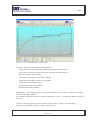
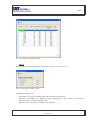
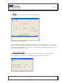
T.A.C.T. 3 T.A.C.T. 3 Terminal for Accurate Control of Temperature User Manual R.A. SYSTEM S.r.l. Via Adamello, 9 20010 Bareggio (MI) Tel +39.02.90362484 Fax +39.02.90362485 Email [email protected] 2007 R.A. System – All rights reserved Ver. 1.2 - 15/06/2009 Page 1 of 43 T.A.C.T. 3 SUMMARY SUMMARY...................................................................................................................... 2 Copyright ....................................................................................................................... 4 1. PURPOSE OF THE DOCUMENT ............................................................................... 5 2. INTRODUCTION......................................................................................................... 5 2.1. AIMS OF T.A.C.T. 3 .......................................................................................................................7 Reduction of lamination troubles; ..................................................................................................7 Consumes reduction ......................................................................................................................7 Emissions reduction.......................................................................................................................8 Oxidation control ............................................................................................................................8 Decarburation control;....................................................................................................................8 Capacity of heating curves repetition.............................................................................................8 Production Efficiency increase.......................................................................................................9 Quality Improvement......................................................................................................................9 2.2. T.A.C.T. 3 ARCHITECTURE........................................................................................................10 Communication ............................................................................................................................11 Core .............................................................................................................................................11 Database......................................................................................................................................12 Interface .......................................................................................................................................12 3.3. T.A.C.T. 3 FUNCTIONS ...............................................................................................................14 Temperature and position tracking ..............................................................................................14 Temperature calculation ..............................................................................................................14 Pace calculation...........................................................................................................................14 Management of stops ..................................................................................................................14 Set-points calculation...................................................................................................................15 3. T.A.C.T. 3 INSTALLATION....................................................................................... 17 3.1. PRELIMINARY STEPS ................................................................................................................17 3.2. ORACLE INSTALLATION ...........................................................................................................17 3.3. T.A.C.T. 3 INSTALLATION..........................................................................................................18 3.4. DATABASE CONFIGURATION ..................................................................................................19 3.5. T.A.C.T. 3 CLIENT PC INSTALLATION .....................................................................................19 4. T.A.C.T. 3 USAGE .................................................................................................... 20 4.1. LAUNCHING T.A.C.T. 3 ..............................................................................................................20 Password .....................................................................................................................................20 Access in client or server mode...................................................................................................20 4.2. T.A.C.T. 3 INTERFACE ...............................................................................................................21 Commands menus.......................................................................................................................22 2007 R.A. System – All rights reserved Ver. 1.2 - 15/06/2009 Page 2 of 43 T.A.C.T. 3 Graph ...........................................................................................................................................29 Data Panels .................................................................................................................................30 4.3 T.A.C.T. 3 CONFIGURATION.......................................................................................................31 Configuration................................................................................................................................31 TACT Codes ................................................................................................................................38 Password Definition .....................................................................................................................39 4.4 TACT CORE..................................................................................................................................39 4.5 TACT COMMUNICATION.............................................................................................................40 5. SYSTEM REQUIREMENTS...................................................................................... 42 6. DOCUMENT’S UPDATES ........................................................................................ 43 2007 R.A. System – All rights reserved Ver. 1.2 - 15/06/2009 Page 3 of 43 T.A.C.T. 3 Copyright This document is supplied just as information. R.A. System does not supply any guarantee, either explicit or implicit about the contained information. The information of the present document, including examples, names, address, can be modified without prior notice. R.A. System denies any liability for mistakes or inaccuracies contained in this document. The respect of all rules applicable on copyright matters is exclusively on the user’s account. All rights protected by copyrights maintained, no part of this document could be reproduced or introduced in any reproduction system, nor transmitted in any form and with any mean (electronic, mechanic, as photocopy, as recording or other) for any purpose, without written authorization by R.A. System. R.A. System may have patents, patent applications, trademarks, copyrights, or other intellectual property rights concerning the contents of this document. Except as expressly provided in a written R.A. System patent agreement, the issuing of this document does not imply any license to the aforesaid patents, trademarks, copyrights, or other intellectual property. The names of actual companies and products mentioned herein may be the trademarks of their respective owners. The companies, organizations, products, persons and the events provided in the following examples are fictitious. Any reference to companies, organizations, products, persons or events is purely accidental. © 2007 R.A.System s.r.l. All rights reserved. 2007 R.A. System – All rights reserved Ver. 1.2 - 15/06/2009 Page 4 of 43 T.A.C.T. 3 1. PURPOSE OF THE DOCUMENT This document describes the functioning of T.A.C.T. 3: the improvement system for heating continuous furnaces, developed by R.A. System. 2. INTRODUCTION T.A.C.T. 3 is typically employed on heating furnaces for the production of billets, slabs, blooms and steel profiles, and that’s the reason why all examples indicated in this document refer to those production processes. Usually, T.A.C.T. 3 receives from company I.T. system (or from the operator managing optimization) the data concerning the production on the run: namely the type of product introduced in the furnace and the required productivity rate. With furnace supervison system, T.A.C.T. 3 sets a bi-directional communication: it receives the temperatures measured in the different areas, air and gas capacities, movement events (chargements, steps, dischargements), tracking data and delays schedulation and it indicates the optimal set-point for each zone. These set-points can be automatically set as adjustment set-point or can be simply displayed on the supervision as suggestion for the operator controlling the furnace. Considering a typical situation, the lower levels at supervision (adjustment and field) are not directly in touch with optimization. That allows installing T.A.C.T. 3 also on already operating plants, simply setting few modifications on the supervision system. In other cases it is also possible to install T.A.C.T. 3 immediately above the adjustment level and make it directly communicate with PLC. This, on one hand, requires a different communication management, but, on the other hand, allows using T.A.C.T. 3 also on plants that do not have any supervision, or where this one cannot be modified. Generally speaking T.A.C.T. 3 can communicate with all main supervision systems and PLC available in the industrial automation environment. 2007 R.A. System – All rights reserved Ver. 1.2 - 15/06/2009 Page 5 of 43 T.A.C.T. 3 PRODUCTION DATA - steel type -product type -productivity -discharge temperature -zone temperature -fumes temperature -air and gas flows -products tracking data -movement events -delays schedulation - zone set-point (in temperature) T.A.C.T. 3 SUPERVISION - controls FURNACE - signals (measures&alarms) Controller Pic. 2.1. Example of automation in steel production. 2007 R.A. System – All rights reserved Ver. 1.2 - 15/06/2009 Page 6 of 43 T.A.C.T. 3 2.1. AIMS OF T.A.C.T. 3 T.A.C.T. 3 is based on a well tested physical-mathematic model of heat exchange that simulates the steel heating process inside the furnace. The system can calculate the conduction and the thermal radiation due to the temperature differences (among products, and furnace vault and atmosphere), the profile of the furnace, the physical-chemical features of the pieces set in the furnace and their positioning (distance among pieces in the furnace and forwarding speed). T.A.C.T. 3 calculates in real time the temperature set point of each zone in the furnace so, that: - The furnace guarantees the required productivity; - The products are output at the required temperature: - The products reach the required temperature in each zone, as late as possible (considering the a.m. points). These aims, together with the functions of T.A.C.T. 3 described later on guarantee the following advantages: • Reduction of lamination troubles; • Consumes reduction; • Emissions reduction; • Oxidation control; • Decarburation control; • Capacity of heating curves repetition; • Production Efficiency increase; • Quality Improvement Reduction of lamination troubles; Namely, the main lamination troubles can be referred to the temperature of the product (too cold, too hot) and to the poor temperature uniformity on the product section. Both these questions are eliminated by T.A.C.T. 3 thanks to its capacity of discharging the product at the exact temperature required by the rolling mill, that can be repeated, reducing at a minimum the differences due to operating conditions. All this leads to a higher reliability and productivity rate of the whole rolling mill. Consumes reduction T.A.C.T. 3 is able to dramatically reduce the fuel consumption thanks to three main guidelines: 2007 R.A. System – All rights reserved Ver. 1.2 - 15/06/2009 Page 7 of 43 T.A.C.T. 3 - As already mentioned, the zones of the furnace are adjusted so, that the product reaches the required temperature as late as possible (considering the set pace, the temperature homogeneity and the technological limits of the plant); - The adaptation capacity as the milling pace varies (and, generally speaking, when the working conditions vary), allows T.A.C.T. 3 to always use the most regular heating curve; - The discharging temperature of the products can be chosen according to the milling energy required for programmed deformation (calibration). As a result different heating curves are generated, variable not only according to the characteristics of the charged product (dimensions and steel quality), but also according to the final profile of the rolled product, of the rolling program and of the working conditions. Emissions reduction The emissions in the atmosphere are directly proportional to consumptions: therefore it is obvious that consumption reduction also guarantee a reduction of pollutant emissions (e.g. CO) in the atmosphere. Oxidation control The quantity (weight) of the product lost by oxidation depends on: - Temperature and time-in-temperature of the product surface; - Composition of the atmosphere around the product. When the combustion occurs around the stechiometric ratio (normal conditions), the oxidation due to the atmosphere composition is insignificant in comparison to that due to high temperature. That means that in normal working conditions, an increase of losses due to oxidation exclusively depends on a longer permanence of the products in a high temperature furnace (which is normally due to stops or pace reductions not balanced by a ready and correct reduction of the zonetemperatures). T.A.C.T. 3 evaluates the permanence time of the product in the different areas of the furnace and can intervene immediately to correct the zone temperatures to maintain two main guidelines: - The products are discharged at correct temperature (and are not overheated); - The products reach the high temperature as late as possible (thus reducing the time-intemperature). Decarburation control; Also the depth of steel decarburation is directly proportional to the surface temperature and to timein-temperature: that’s why the same principles that allow T.A.C.T. 3 to reduce oxidation, also guarantee the decarburation reduction. Capacity of heating curves repetition T.A.C.T. 3 is set up thanks to the collaboration of a process engineer and/or with expert operators. 2007 R.A. System – All rights reserved Ver. 1.2 - 15/06/2009 Page 8 of 43 T.A.C.T. 3 This fact, together with a lower need of human intervention on the furnace control, guarantees the optimal performance of the plant, also with respect to changing working conditions. This dramatically reduces the risk that the furnace supervision performed by less skilled operators increases the consumptions and reduces the productivity and/or quality of the products. Furthermore these operators can find in T.A.C.T. 3 a tool adequate to supply information and data concerning the furnace that will be useful for a quick professional growth. Production Efficiency increase The guarantee that products are discharged at the required temperature eliminates rolling troubles and the risk to reduce the furnace pace, particularly as consequence of a top: T.A.C.T. 3 therefore reduces at minimum the production drops. On the other hand, knowing the temperature of each charged product, it is possible to detect possible increase margins of production rate. Quality Improvement All benefits listed and the regular production guaranteed by T.A.C.T. 3 can result in a generally increase of the average quality of the discharged products. 2007 R.A. System – All rights reserved Ver. 1.2 - 15/06/2009 Page 9 of 43 T.A.C.T. 3 2.2. T.A.C.T. 3 ARCHITECTURE T.A.C.T. 3 is composed by different programs (all developed in C++) and works on Oracle database (v. 10G Express Edition). T.A.C.T. 3 fundamental programs are: - Core: is the simulator containing the mathematic model that calculates the products’, vault’s, and waste gas’ temperatures and consequently modifies zone’s set-point; - Communication: is the tool that manages the communication between T.A.C.T. 3 and external environment, i.e. automation level 1 and the factory information system; - Interface: is the set of windows and controls available for the operator. T.A.C.T. 3 T.A.C.T. 3 OPERATOR’S INTERFACE ORACLE DATA BASE CORE POSITION AND TEMPERATURE TRACKING TEMPERATURE CALCULATION FACTORY INFORMATION SYSTEM PACE CALCULATION T.A.C.T. 3 COMMUNICATION DELAYS MANAGEMENT - PRODUCTION MANAGEMENT - QUALITY CONTROL SETPOINTS CALCULATION FURNACE MOVEMENT AND REGUALTION SYSTEM - TEMPERATURES & SETPOINTS - CAPACITY - TRACKING Pic. 2.2. T.A.C.T. 3 structure. In order that T.A.C.T 3 optimizes the plant adjustment, the database engine and the two programs “Core” and “Communication” must always operate: the operator interface, on the contrary, can be shut down without compromise system results. 2007 R.A. System – All rights reserved Ver. 1.2 - 15/06/2009 Page 10 of 43 T.A.C.T. 3 In the typical situation, all T.A.C.T. 3 programs run on the same PC (which could also be the same on which the furnace supervision is installed). It is also possible to get different copies of the interface application of T.A.C.T. 3 running on other PCs net-linked. In this case there is a ‘server’ optimization PC where it is possible to use all T.A.C.T. 3 functions and other “n” ‘client’ PC working as displays of the optimization system. Communication The communication program transfers the data between level 1 and T.A.C.T. 3 database: this implies that this program too has to always be running to grant T.A.C.T. 3 correct functioning. Pic. 2.3. T.A.C.T. 3 communication program. Data exchange is based on text files (CSV) and foresees that: - Level 1 generates a file for each movement event or when a timer expires; - T.A.C.T. 3 reads the file (or the files) coming from level 1and generates an answer file. The easiness of this method is a grant about its strength and its capability of being used in the most different hardware and software configurations. Core T.A.C.T. 3 Core it is the calculation system based on mathematical model that simulates the steel heating process within furnace. This program reads, processes and updates all data contained in the database and it always must be working to grant T.A.C.T. 3 correct functioning. 2007 R.A. System – All rights reserved Ver. 1.2 - 15/06/2009 Page 11 of 43 T.A.C.T. 3 Pic. 2.4. T.A.C.T. 3 core program. Database As already pointed out, T.A.C.T. 3 has been developed over Oracle Express Edition version 10G (free version). This database grants the required performances in data access even on a normal PC. Besides, the Oracle database can be easily queried through an ODBC driver that allows exporting data right within programs such as MS Excel® for possible off-line analysis. Interface This part of the system contains all displays and controls available. As previously mentioned, this program has not to be necessarily installed on the same PC hosting the other two components of T.A.C.T. 3 and it is also possible to have different interface systems connected to the same Core. The graphical interface follows the style commonly used by MS Windows® applications. In the main screen of T.A.C.T. 3 are shown the curves concerning the heating of the products currently in the furnace. The horizontal axis represents the longitudinal section of the furnace (in mm), while on the vertical axis are indicated the temperature scales (in °C) and decarburation and oxidation depth (in m). 2007 R.A. System – All rights reserved Ver. 1.2 - 15/06/2009 Page 12 of 43 T.A.C.T. 3 Pic. 2.5. T.A.C.T. 3 interface program main window. The curves that can be displayed by the operator are: - Temperature of furnace combustion chamber (for upper and lower zones); - Temperature of waste gas within the furnace (for upper and lower zones); - Mean temperature of the product; - Temperature of the upper surface of the product; - Temperature of the lower surface of the product; - Temperature of the product’s core; - Decarburation depth of the product; - Oxidation depth of the product. Furthermore a green horizontal line is displayed to indicate the temperature target that should be reached by the output product. If the product exiting from the zone is too cold or too hot, T.A.C.T. 3 respectively displays a blue or red area. In the area over the graph it is represented the current furnace’s charge (seen from high). Clicking on any product, its data are shown in lower panels. 2007 R.A. System – All rights reserved Ver. 1.2 - 15/06/2009 Page 13 of 43 T.A.C.T. 3 3.3. T.A.C.T. 3 FUNCTIONS All main simulation and calculation functions of T.A.C.T. 3 are managed by Core program: here’s a short description. Temperature and position tracking Through the analysis of the information received from the movement system, T.A.C.T. 3 is able to define the position of any single product inside the furnace. Each product is associated to a table containing the management data and the heating data: abscissa (position along the furnace), charging row, lot, id, cast number, quality of the steel, size, mean temperature, temperature of upper surface, temperature of lower surface, core temperature, difference between mean temperature and objective, oxidation thickness, decarburation depth, time of permanence in the furnace. These data are analyzed by the Core’s mathematic model to calculate temperatures and set points, but are also available for the operator, to be displayed in any moment on the interface program. Temperature calculation The mathematic model used by T.A.C.T. 3 Core can calculate, along all the furnace profile, the most relevant temperature values for each product in the furnace. This extremely detailed knowledge of the charge in the furnace is the main issue that allows T.A.C.T. 3 to define the optimal set points for each zone. Other optimization systems based on empirical tables, supply similar functions, but cannot reach the accuracy (even considering external events) ensured by the mathematic model. Pace calculation The pace calculation verifies what is the real production of the furnace on the basis of the signals deriving from the movement. This is how T.A.C.T. 3 succeeds in calculating exactly the permanence times of each product in the different zones of the furnace, and, as a consequence, is able to match the set point values to maintain the products on the correct heating curve (also in correspondence of stops, not declared by the operator). Management of stops Stops are the interruptions in rolling and movement of the products and can be managed differently by T.A.C.T. 3 in case of: - Programmed stops: normally due to programmed maintenance interventions. These are notified in T.A.C.T. 3 (or in supervision in advance, therefore the system “knows” when the stop will start and how long will it last. - Unforeseen but declared stops: normally due to troubles downstream the furnace or in the furnace itself. In the moment in which the operator detects the problem, he confirms the stop in 2007 R.A. System – All rights reserved Ver. 1.2 - 15/06/2009 Page 14 of 43 T.A.C.T. 3 T.A.C.T. 3 indicating the possible running time: that means that even in this case the system recognize beginning and running time of the stop but just when it occurs. - Unforeseen and not declared stops: differently from the previous ones, no statement is performed in T.A.C.T. 3 therefore the system does not know the starting time nor the running time of the stop: it is simply detected by the missing movement. In any case the immediate effect of these stops is a longer permanence time of the products in the furnace, which causes an overheating of the products leading to rolling, oxidation and decarburation troubles, and waste of fuel. T.A.C.T. 3 is able to eliminate or at least reduce at a minimum level, these problems, thus progressively reducing the zone set points. Best optimization is reached on programmed stops, where T.A.C.T. 3 is able to make that: - Last product that will reach discharge position before stop’s beginning will be at desired temperature. - Following products will be left cooling even before stop’s beginning, because the system knows that they will be discharged only after stop’s end. - Furnace’s zone will be then reheated so that, at the end of furnace’s stop, last product will be immediately ready to be discharged at its correct temperature. Same logic is also used for stops declared just before their beginning, but, in these cases, it is not possible to start the preventive lowering as soon as in previous case. For what concern not declared stops, instead, T.A.C.T. 3 gradually lowers zones’ set-points so to try to keep all products on their heating curve: last product can be discharged at any time. It is clear that in this last case T.A.C.T. 3 optimization is noticeably lower than in both previous cases. Set-points calculation The calculation of zone set-points is based on three main parameters: products temperature, foreseen permanence time (depending on furnace pace) and optimal heating curve. The optimal heating curve is expressed by “zone targets” setting the average temperature that the product should have at the exit of each area. The operator can define different curves according to: - Size of the charged products; - Belonging group (i.e. the chemical composition of steel); - Type of finished product (i.e. the energy of foreseen rolling); - Discharging pace. When the real pace differs from the one theoretically set, T.A.C.T. 3 performs an interpolation of the set values to obtain optimal zone targets. 2007 R.A. System – All rights reserved Ver. 1.2 - 15/06/2009 Page 15 of 43 T.A.C.T. 3 The products’ temperature and the related permanence times are calculated by the corresponding functions, described above. 2007 R.A. System – All rights reserved Ver. 1.2 - 15/06/2009 Page 16 of 43 T.A.C.T. 3 3. T.A.C.T. 3 INSTALLATION In this chapter T.A.C.T. 3 server version (that is the complete system with core program, communication and database) installation is described. In paragraph 3.5.T.A.C.T. 3 client version (that is the interface system that shows data from a T.A.C.T. 3 database reachable via ethernet) installation is described. Any setup file hereafter described is available on T.A.C.T. 3 PC (usually in C:\TACT_SETUP folder) and in T.A.C.T. 3 CD supplied by R.A. System. 3.1. PRELIMINARY STEPS It is suggested, before starting different installations for T.A.C.T. 3 environment, to disable any antivirus and firewall software that could be eventually re-enabled at the end of installation process. 3.2. ORACLE INSTALLATION First step to install T.A.C.T. 3 on a PC is Oracle XE installation. This installation can be performed following the wizard launched by OracleXEUniv.exe setup file. The only available options are the choice about where to install it (default path is C:\oraclexe\) and the password assigned to SYS and SYSTEM users. Pic. 3.1. Oracle installation path setting window. 2007 R.A. System – All rights reserved Ver. 1.2 - 15/06/2009 Page 17 of 43 T.A.C.T. 3 Pic. 3.2. SYS and SYSTEM users password definition window. To grant the correct functioning of DB configuration scripts hereafter described, password must be: rasyssrl 3.3. T.A.C.T. 3 INSTALLATION T.A.C.T. 3 installation can be performed launching Setup_TACT3_server.exe program and following the wizard. Installation process does not foresee any option (T.A.C.T. 3 is installed in C:\TACT3\ folder). Note: Once process installation has been completed, it is necessary to open TACT3_Interfaccia.INI file (in folder C:\tact3\Exec\) and to modify “SERVER” line typing in the network name of TACT server PC. When T.A.C.T. 3 is installed, plug in the hardware key supplied by R.A. System in any USB port, and then install the GSS driver used to correctly manage that hardware key. This installation is executed by SmartKeyDriversInstaller.exe program that does not foresee any option. At this point it is necessary to configure a network path (typically Z:\) that will be automatically reconnected at startup, pointing to the supervision PC’s folder where communication text files are written (this means that this folder’s share needs the writing permissions too). 2007 R.A. System – All rights reserved Ver. 1.2 - 15/06/2009 Page 18 of 43 T.A.C.T. 3 3.4. DATABASE CONFIGURATION Once installed both OracleXE and T.A.C.T. 3 have been installed, it is necessary to configure the Oracle that will be used T.A.C.T. 3. As first step, it is required to execute the Init_DB_TACT.bat from C:\TACT3\Init\ folder, that will configure the Oracle XE DB to have it usable by T.A.C.T. 3. Note Please check the DOS window opened by Init_DB_TACT batch program and press the space bar each time that “Press any key to continue” (“Premere un tasto per continuare”). DOS window will be automatically closed at the end of batch program. At this point it is possible to start T.A.C.T. 3 launching TACT3_Interfaccia.exe program from C:\TACT3\EXEC\ folder. Once the interface program is running, it is possible to start core and communication programs with the apposite menus. 3.5. T.A.C.T. 3 CLIENT PC INSTALLATION To install a T.A.C.T. 3 client PC: - Install OracleXE as already described in paragraph 3.2; - If needed, disable the automatic startup of Oracle service to save PC resources; - Install T.A.C.T. 3 with Setup_TACT3_client.exe program; - Plug in the hardware key supplied by R.A. System and install its driver as already described in paragraph 3.3. Note. Once installed it is necessary to open the TACT3_Interfaccia.INI file (in C:\tact3\Exec\ folder) and to open the “SERVER” line typing in the network name of TACT server PC. For client PC it is not necessary to configure Oracle database, nor to connect the network paths described in paragraph 3.3. On the contrary, it is required that client PC is on the same network of server PC, so that it is possible to access to the Oracle database through its apposite ODBC driver. 2007 R.A. System – All rights reserved Ver. 1.2 - 15/06/2009 Page 19 of 43 T.A.C.T. 3 4. T.A.C.T. 3 USAGE 4.1. LAUNCHING T.A.C.T. 3 To start T.A.C.T. 3, click on the desktop shortcut or execute the TACT3_Interfaccia.exe program from “C:\Tact3\Exec” folder. Password On program startup a password is required to login. This password is then used to enable application’s menu. Default password is TACT3, but after having logged in it is possible (if current user has the required authorizations) to add, to edit or to delete passwords. Access in client or server mode Once logged in, T.A.C.T. 3 shows if it is going to be launched as client or as server. Pic. 4.1. T.A.C.T. 3 starting window. 2007 R.A. System – All rights reserved Ver. 1.2 - 15/06/2009 Page 20 of 43 T.A.C.T. 3 If TACT runs as Server, it is possible to launch the Core and the Communication programs and it is also possible to change the parameters of the system. It TACT runs as client, only the Interface is available and the parameters can be consulted (with the appropriate password) but not changed. 4.2. T.A.C.T. 3 INTERFACE Hereafter main T.A.C.T. 3 interface window is shown. Pic. 4.2. Main T.A.C.T. 3 interface window. This window is composed by following elements: - Commands menus: they give access to all program’s main functions and are described hereafter in this chapter. - State panel: it shows R.A. System logo and another one that can be configured (file C:\TACT3\LogoCustomer.bmp), then it shows the state of Core and Communication programs (correspondent lamps are red if programs are inactive) and finally it allows to set whether to show or not the areas about cold and/or warm products. In detail, clicking on Area will show the possible blue or red areas indicating that the product exiting the zone is too cold or too hot. 2007 R.A. System – All rights reserved Ver. 1.2 - 15/06/2009 Page 21 of 43 T.A.C.T. 3 When these areas are visible it is also possible to set whether to show them fully colored or in transparent way (so to see the under laying curves) through the Transparent check box. - Tracking panel: it shows a plan view of furnace’s current charge. This plan shows each product sized and placed depending on the ratio between furnace’s physical dimensions and the panel’s dimensions. This means that, typically, furnace is represented very stretched out and so products appear much tubbier than their real shape. Selected product (whose data are shown in lower panels) appears green, while all the others are white. L, C and R letters indicate the three rows (Left, Center and Right) on which it is theorically possible to charge products. - Graph: it shows all the curves managed by program and it is described hereafter in this chapter. - Data panels: they show all data of tracking selected product and, eventually, those about current or scheduled delay. These panels too are described hereafter in this chapter. Commands menus Hereafter there is the complete list of all the functionalities available to the operator through the commands menus. Note: Generally, to apply a modification it is necessary to click on Save button. Clicking on Exit button will only close the current window without saving any possible done modification. Curve selection In curve selection window it is possible to manually set the belonging heating curve of each new product charged. This setting works only if the Control setting within the communication program is set on TACT3 (see the description of communication program). If it is not, the heating curve of each charged product is communicated by level 1 system. The Product green highlighted cell indicates the heating curve of last charged product. 2007 R.A. System – All rights reserved Ver. 1.2 - 15/06/2009 Page 22 of 43 T.A.C.T. 3 Pic. 4.3. Heating curve selection window. Pacing In this window it is possible to set the pacing type (steps/h) used by T.A.C.T. 3. Pic. 4.4. Pacing type selection window. Available pacing types are: - Theoretical: it uses the theorical pacing value of current heating curve; - Measured: it calculates the effective pacing depending on steps events received from supervision (this is the type normally used); - Manual: it uses a fixed value manually set by operator. 2007 R.A. System – All rights reserved Ver. 1.2 - 15/06/2009 Page 23 of 43 T.A.C.T. 3 Delays In this window it is possible to manage the scheduling of delays. Pic. 4.5. Delays management window. In typical situation, communication program control bit is set on “Supervision”, so in T.A.C.T. 3 delays management window it is only possible to read the delays scheduled in supervision software. On the contrary, if control bit is set on T.A.C.T. 3, in this window it is possible to define new delays or to delete the already scheduled ones. Disch. Temp. Correction With this command it is possible to temporary modify the discharging temperature of products. Such correction remains active until a product with a different heating curves comes. Pic. 4.6. Discharging temperature correction window. 2007 R.A. System – All rights reserved Ver. 1.2 - 15/06/2009 Page 24 of 43 T.A.C.T. 3 Show In this window it is possible to manage the graphic’s visualization in T.A.C.T. 3 interface main window. For each curve it is possible to: - Set whether to show it or not, clicking on its check box; - Define the width of drawn line selecting the desired number in the numeric cell (it is possible to set values between 1and 4); - Set the line color, clicking on the curve description and selecting the desired color. Color selection can also be done for the current temperature values and set-points, and for graph’ back colors (Panel start and end color). Reference Product checkbox sets whether to show or not the pointers that indicate which is the reference product on each zone. Pic. 4.7. Display managing window. Historics Through this menu it is possible to reach: - Product historics: it contains the heating curves of each product re-heated in last three months; - Zone historics: it contains the history of each zone (zone temperature, set-point, target and mean temperature of reference product) in last three months; - Discharging historics: it contains the history of dischargements (discharge date and time, product mean temperature, target, decarburation and oxidation depths and time in furnace) in last three months. Product historics In this window there are all the heating curves about stored products. 2007 R.A. System – All rights reserved Ver. 1.2 - 15/06/2009 Page 25 of 43 T.A.C.T. 3 Pic. 4.8. Product historics showing window. Through the upper left boxes it is possible to define what products to show, setting the time interval containing the desired dischargements. These products are shown in the left list: clicking on one of this record, all of its data are shown both in graph and in lower panels. These fields are updated depending on the step selected with the cursor over the graph. In the graph it is possible to show all data about re-heating process of selected product. Each numerical data in lower panel is surrounded by a frame of the same color of the concerning curve. Such colors can be changed through the Legend menu, while Print, Save and Exit menus respectively allow printing the currently shown graph, saving it in .bmp format and closing the window. The three upper left buttons (with the hand lens and the ban) can be used to zoom in and out the graph. It is also possible to zoom in the graph making a selection from left to right on the desired area (keeping the mouse left button clicked). Repeating the same operation from right to left, any zoom is canceled. Zone historics In this window it is possible to see the history of each zone. 2007 R.A. System – All rights reserved Ver. 1.2 - 15/06/2009 Page 26 of 43 T.A.C.T. 3 Pic. 4.9. Zone historics showing window. Through the upper boxes it is possible to define what product to show. Once having typed the desired interval, it is necessary to click the button with the two green arrows to update the window. In left list it is possible to select the desired zone: clicking on one of this record, all of its data are shown both in graph and in lower panels. These fields are updated depending on the moment selected with the buttons over the graph. In the graph it is possible to show all data about re-heating process within selected zone. Each numerical data in lower panel is surrounded by a frame of the same color of the concerning curve. Such colors can be changed through the Legend menu, while Print, Save and Exit menus respectively allow printing the currently shown graph, saving it in .bmp format and closing the window. The three upper left buttons (with the hand lens and the ban) can be used to zoom in and out the graph. It is also possible to zoom in the graph making a selection from left to right on the desired area (keeping the mouse left button clicked). Repeating the same operation from right to left, any zoom is canceled. Discharging historics In this window it is possible to show all data about recorded dischargements. 2007 R.A. System – All rights reserved Ver. 1.2 - 15/06/2009 Page 27 of 43 T.A.C.T. 3 Pic. 4.10. Discharging historics showing window. Through the upper boxes it is possible to define what period to show. Once having typed the desired interval, it is necessary to click the button with the two green arrows to update the window. In left list it is possible to select the desired dischargement: clicking on one of this record, all of its data are shown both in graph and in lower panels. These fields are updated depending on the moment selected with the buttons over the graph. In the graph it is possible to show the discharging target, the product’s mean temperature, the decarburation and oxidation depths and the time in furnace for each product. Each numerical data in lower panel is surrounded by a frame of the same color of the concerning curve. Such colors can be changed through the Legend menu, while Print, Save and Exit menus respectively allow printing the currently shown graph, saving it in .bmp format and closing the window. The three upper left buttons (with the hand lens and the ban) can be used to zoom in and out the graph. It is also possible to zoom in the graph making a selection from left to right on the desired area (keeping the mouse left button clicked). Repeating the same operation from right to left, any zoom is canceled. Save Using Save menu it is possible to generate a bitmap file containing the currently shown window. 2007 R.A. System – All rights reserved Ver. 1.2 - 15/06/2009 Page 28 of 43 T.A.C.T. 3 Print Using Print menu it is possible to print out on paper the currently shown window. Parameters Through this menu it is possible to access to the system configuration functionalities. For a detailed description of these parameters, please see next chapter “T.A.C.T. 3 configuration”. TACT Core Start Using TACT Core Start menu it is possible to restart T.A.C.T. 3 calculation program in the case it has been shut down. This menu is only available on Server PC. Communication Start Using Communication Start menu it is possible to restart T.A.C.T. 3 communication program in the case it has been shut down. This menu is only available on Server PC. Language Clicking on Language menu, it is possible to choose the language into which T.A.C.T. 3 interface has to be translated. In typical configuration available languages are Italian, English and Custom. Custom language can be modified by the customer himself, opening the C:\Tact3\Language\Language.xls file and updating all the translations in CU column (from default they are identical to English translations). Note: Columns Form and Field in language.xls file must NEVER be changed. Login Clicking on Login menu it appears the password request (as at start time) and until a valid password is typed in, it is not possible to use the interface program anymore. This means that this menu item can be used as “Screen blocking” function to avoid the access of undesired users. Exit Clicking on Exit menu the program goes back to the starting page (without password request). Graph As already described in paragraph “Commands menus – Show” it is possible to set which curves to show, with what colors and width. 2007 R.A. System – All rights reserved Ver. 1.2 - 15/06/2009 Page 29 of 43 T.A.C.T. 3 It is also possible to show the areas that highlights too cold or too hot products exiting from the zones and, in case, to decide if these areas must be fully colored or transparent. The color set for each curve is also used as frame of the relative numerical filed shown in lower panels. Such colors are stored in application’s .ini file, so that user customization will be kept. On the graph there are: - Y left axis: it is the temperature scale (in °C) to which all temperature curves are referred; - Y right axis: it is the depth scale (in referred; - X axis: it is the abscissa (in mm) within furnace, starting from charging side towards discharging; - Dashed red lines: they indicates the limits of regulation zones; - PV: it is the value (in °C) of measured temperature in each zone; - SP: it is the value (in °C) of temperature set-point calculated by T.A.C.T. 3. m) to which oxidation and decarburation curves are It is possible to zoom in the graph making a selection from left to right on the desired area (keeping the mouse left button clicked). Repeating the same operation from right to left, any zoom is canceled. Data Panels In window’s lower side there are the following data: - Mean Temp. [°C]: it is the calculated temperature that expresses how much heat has been absorbed by selected product. Frame has the same color of correspondent curve in graph. - Top Temp. [°C]: it is the calculated temperature of selected product’s top surface. Frame has the same color of correspondent curve in graph. - Bottom Temp. [°C]: it is the calculated temperature of selected product’s bottom surface. Frame has the same color of correspondent curve in graph. - Core Temp. [°C]: it is the calculated temperature of selected product’s central point. Frame has the same color of correspondent curve in graph. - Resid. Time [H and min]: it is the elapsed time between selected product’s chargement and present moment. - Curve: it is the selected product’s heating curve. - Target Temp. [°C]: it is the target that selected product’s mean temperature has to reach when it will exit the current zone. Frame has the same color of correspondent curve in graph. - Deviation [°C]: it is the difference between selected product’s mean temperature and target temperature. - Eq. Prod. Rate [steps/h]: it represents the calculated pace kept by product within the furnace. - Pacing mode: it is the pacing setting. - Step/h: it is the pacing value measured by the system. 2007 R.A. System – All rights reserved Ver. 1.2 - 15/06/2009 Page 30 of 43 T.A.C.T. 3 - Prod/h: it is the number of products discharged in the last hour. - Number: it is the incremental number (ID) related to selected product. - Length [mm]: it is the selected product’s length (distance between left and right surfaces). - Width [mm]: it is the selected product’s width (distance between forward and backward surfaces). - Thickness [mm]: it is the selected product’s thickness (distance between upper and lower surfaces); - Abscissa [mm]: it is selected product’s backward surface position within furnace. - Lot: it is the production lot code to which selected product belongs. - Prod. ID: it is the unambiguous identity code of selected product. - Heat: it is the code of heat from which selected product comes. - Side: it is the furnace’s side where product has been charged. In lower right panel there are data about next possible scheduled delay (or current delay). 4.3 T.A.C.T. 3 CONFIGURATION Clicking on “Parameters” menu from T.A.C.T. 3 main interface window, it is possible to access all program’s configuration parameters. Configuration “Configuration” menu opens a window from which it is possible to access all T.A.C.T. 3 configuration parameters hereafter described. Note: it is recommended to be very careful in changing any parameter, because it should compromise the system’s correct functioning. 2007 R.A. System – All rights reserved Ver. 1.2 - 15/06/2009 Page 31 of 43 T.A.C.T. 3 Pic. 4.11. Configuration parameters access window. Furnace Configuration In this window it is possible to define furnace’s structure and main parameters of each zone. Each of the 20 foreseen zones (10 upper and 10 lower) can be activated/deactivated through right click on its row (note: zone 9 MUST always be activated). For each zone it is required to define maximum and minimum temperature set-point, its thermal inertia (that is maximum speed of temperature raises) and its response time (that defines its capacity of heating products). Pic. 4.12. Furnace configuration window. 2007 R.A. System – All rights reserved Ver. 1.2 - 15/06/2009 Page 32 of 43 T.A.C.T. 3 Furnace Dimensions In this window there are all geometrical data about furnace. Pic. 4.13. Furnace dimensions configuration window. In two lower tables there are all furnace’s zones (bottom and top) with these data: - Description. - Zone End Abscissa: it is the abscissa (in mm) where zone ends. - Zone Height: it is the vault height (in mm) of the zone. - TC Abscissa: it is the abscissa (in mm) where the zone thermocouple is. - TC Depth: it indicates (in mm) how much the thermocouple pokes out from the vault; 0 means that TC is flush-mounted, while –1 means that there is no TC. - Fuel Max Flow: it is the maximum fuel flow (in Nm3/h) for the zone. - Air Max Flow: it is the maximum air flow (in Nm3/h) for the zone. Besides: - First numerical column for top zones indicates the zone number (note: last zone is always n. 9). - Master U. Zone for bottom zones indicates the number of upper zone to which current bottom zone refers. - Offset SP for bottom zones indicates the temperature delta between current lower zone and its reference top zone used to calculate bottom set-point. In window’s upper side it is possible to define: - Panels (top and bottom): for each zone it is defined where the possible panel is. 2007 R.A. System – All rights reserved Ver. 1.2 - 15/06/2009 Page 33 of 43 T.A.C.T. 3 - Physical dimension of combustion chamber: length, width, maximum height of top and bottom zones. - “Line Width”: it is usually set as 1/3 of furnace’s width and it is only used to correctly size products in tracking panel. - In “USEFUL FURNACE LIMITS”, “Begin” and “End”: they indicate the re-heating useful zone: it typically starts at the end of recuperative zone and ends around the middle of soaking zone. - In “USEFUL FURNACE LIMITS”, “Min. Discharging Pos.” and “Min. Charging Pos.”: they indicate the minimum abscissa where it is possible to charge and discharge products (they depends on furnace and machineries design). - Shortening: it allows to set how much first active zone (top and bottom) can be shortened in case furnace foresees it. The check box is read only and it indicates whether shortening is currently active or not (signal coming from communication). System Configuration In this window there are all main parameters used by calculation thermal model and, moreover, from furnace simulation system. All of these parameters should not be changed without having discussed it with R.A. System. Pic. 4.14. Thermal configuration window. Product Configuration In this window it is possible to define all products (that is the re-heating curves) that can be charged in furnace. For each curve there is: - The heating curve ID number. - A short textual description with colored background: as shown in the upper side of the window, white background means that product is square (billet, bloom or slab), yellow background means that product is a pipe, and cyan background means that product is a round full bloom. 2007 R.A. System – All rights reserved Ver. 1.2 - 15/06/2009 Page 34 of 43 T.A.C.T. 3 - Product’s physical dimensions: length, width, thickness and diameter. When defining new product available fields are: length, width and thickness for square product, length, thickness and diameter for pipe and length and diameter for round. - Discharging temperature: it is the target that product’s mean temperature must reach at discharging time. - Theoretical Pacing: it is the theorical pacing (in dischargements/h) that this kind of product should keep during normal plant working for its nominal production. - TACT3 Code: it is the steel re-heating code generated by TACT Code program depending on material chemical composition. Pic. 4.15. Products configuration window. Targets Configuration In this window it is possible to set temperature targets for each furnace’s zone. Advice: it is suggested to define two heating curve for each product: first one at theoretical pacing and another one at a much lower pacing. In this way the system can generate different target temperatures for the same product depending on furnace speed. 2007 R.A. System – All rights reserved Ver. 1.2 - 15/06/2009 Page 35 of 43 T.A.C.T. 3 Pic. 4.16. Targets configuration window. Directory and Param. In this window there are all the used paths and other various parameters. First three folders are set during the installation and should never be changed. “HMI directory communication” contains the path pointing to the folder where data exchange files are read and written. Usually this is a folder of supervision PC, shared on the network and mapped on T.A.C.T. PC (in following example Z:\ disk). Note: in this parameter, the backslash character (\) must always be written twice (so Z:\ path becomes Z:\\). “Communication file prefix” contains the three characters that precede data and time in supervision data file name (typically DAT). 2007 R.A. System – All rights reserved Ver. 1.2 - 15/06/2009 Page 36 of 43 T.A.C.T. 3 Pic. 4.17. Path configuration + other parameters window. Lower parameters are system settings about database and thermal calculation that should never be changed without having discussed it first with R.A. System. Delays Parameters In this window it is possible to define delays main parameters. The parameter “Short delay limit value” defines what delays are considered short (during which the system continues to simulate the heating process and it manages the set-points thereby) and what are long (during which set-points are lowered to preset values regardless of the products temperatures). We suggest to avoid setting this parameter over 60 minutes. Pic. 4.18. Delays parameters window. In lower left panels it is possible it is possible to define the set-points lowering (in °C) for each zone depending on long delay length (in minutes). To have a correct functioning, it is better to set: - First lowering by the same duration set in previous parameter (Short delay limit value); - Last lowering on duration 9999, so that there never will be a longer delay (since it has no sense to declare a delay longer than a day). In reported example, soaking zone set-point is lowered 45°C for delays long between 30 and 60 minutes, while for delays included between 60 and 120 minutes, set-point is lowered 60°C, etc. In lower right panel it is possible to set the maximum set-point lowering for each cycle calculation for each zone. “Auto” option leaves the system free to lower without any limit. 2007 R.A. System – All rights reserved Ver. 1.2 - 15/06/2009 Page 37 of 43 T.A.C.T. 3 Set Point Filtering In this window there are the filtering criteria that are applied to set-point modification to avoid swinging behavior and great jump between last calculation and previous one. It is also possible to define the maximum difference between TACT calculated set-point and measured temperature in each zone. All of these parameters should not be changed without having discussed it with R.A. System. Pic. 4.19. Set-point filtering window. Empty Furnace With this command it is possible to delete all products currently in furnace and to restart with tracking database completely empty. TACT Codes This command starts a program that can be used to generate the steel re-heating code (TACT code) depending on material chemical composition. 2007 R.A. System – All rights reserved Ver. 1.2 - 15/06/2009 Page 38 of 43 T.A.C.T. 3 Pic. 4.20. TACT code generation program. Password Definition In password definition window it is possible to create new users or to modify the existing ones. For each user it is possible to set what menus are visible and what are editable (that is it is allowed to save modifications). Pic. 4.21. Password definition window. 4.4 TACT CORE 2007 R.A. System – All rights reserved Ver. 1.2 - 15/06/2009 Page 39 of 43 T.A.C.T. 3 Pic. 4.22. T.A.C.T. 3 Core program window. TACT CORE program window shows: - Program state; - Time when last calculation has been done and its duration; - Time missing to next execution of each calculation (red horizontal barographs); - Schedulation settings about temperature and set-points calculations. All of these parameters should not be changed without having discussed it with R.A. System. TACT CORE program window it is automatically minimized every 30 seconds. 4.5 TACT COMMUNICATION Pic. 4.23. T.A.C.T. 3 program window. COMMUNICATION program window shows: 2007 R.A. System – All rights reserved Ver. 1.2 - 15/06/2009 Page 40 of 43 T.A.C.T. 3 - Communication status; - Date and time of communication startup; - Last recorded error and number of happened errors; - List of currently present data files; - List of detected errors during data reading. In window lower side it is possible to set the control bit that defines who can: - Set (or schedule) new delays; - Define the belonging heating curve for new charged products. In usual exercise conditions, this setting has to be on SUPERVISION. COMMUNICATION program window it is automatically minimized every 30 seconds. 2007 R.A. System – All rights reserved Ver. 1.2 - 15/06/2009 Page 41 of 43 T.A.C.T. 3 5. SYSTEM REQUIREMENTS T.A.C.T 3 needs a PC connected to plant’s level 1 via ethernet. In typical configuration (one single PC that manages all T.A.C.T. 3 programs, including the database engine), PC requirements are: HARDWARE Minimum Recommended CPU: Pentium 4 1Ghz Pentium 4 2Ghz or higher RAM memory: 512 MB 1 GB or higher Hard Disk: 20 GB 80 GB or higher Video Card: SVGA color SVGA color Ethernet Card: 10Mbps 100Mbps or higher Monitor: 17” (1280x1024) 19” or higher (1280x1024) SOFTWARE T.A.C.T. 3 PC requires a MS Windows® operating system (minimum required Windows 2000, recommended XP) and Oracle database engine v. 10. It is finally recommended a color printer to emphasize any possible print of re-heating curves graph. 2007 R.A. System – All rights reserved Ver. 1.2 - 15/06/2009 Page 42 of 43 T.A.C.T. 3 6. DOCUMENT’S UPDATES Version 1.0 - 20/09/2007 Starting version. Version 1.1 - 24/04/2009 Modified the client-server starting mode. Added the product type in Product Configuration. Added the temperature-set point maximum delta in set point filtering. Version 1.2 - 15/06/2009 Defined the Oracle DB password to be defined during setup. 2007 R.A. System – All rights reserved Ver. 1.2 - 15/06/2009 Page 43 of 43