1
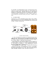
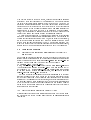
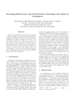
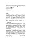
Formal Verication as a Design Tool
-the Transponder Lock ExampleR. Budde, A. Merceron, K.-H. Sylla
GMD - SET-EES, SchloBirlinghoven
D-53754 Sankt Augustin
email: freinhard.budde,merceron,[email protected]
Abstract
We describe a methodology for the construction and validation of embedded systems with real-time constraints. Our methodology is based on
object-oriented techniques and synchronous programming. This greatly
eases the use of formal verication to analyse the system, particularly to
support design decisions. We use model checking to verify reactive behaviors and theorem proving to verify datatype behaviors. Our approach
has been applied to develop industrial products. It is illustrated here
with such a development, a transponder lock.
1 Introduction
Technical systems today comprise a variety of mechanical, electrical, electronic
and software components. Software-design has become a crucial task in the
design of embedded systems. Such systems have to fulll strict requirements
towards reliability, dependability and real-time properties since they have to
react on time to stimuli of their environment.
Our methodology to design embedded systems is based on object-oriented
techniques and synchronous programming. Object-oriented techniques allow
to achieve the necessary and appropriate exibility in software design while
synchronous programming is well suited to specify real-time constraints.
We use object oriented methods during the whole development process to
partition the system into classes. Classes are the units of information hiding
and reuse. Every class has a datatype behavior as usual in the object-oriented
paradigm. A class is called reactive if it additionally denes a reactive behavior.
These two aspects of a reactive class, reactive and datatype behavior, have a
sound integration via synchronous programming. Synchronous programming is
based on the synchrony hypothesis which stipulates that systems produce their
outputs synchronously with their inputs [1]. A consequence is that timing issues
may be abstracted in the rst stage of the system design, see section 3.
Formal verication (model checking for reactive behavior, and theorem
proving for datatype behavior) is used to analyze the system. The partitioning
0 This work was partly supported by a grant from the German-Isreali Foundation for
Scientic Research and Development (GIF) under contract number G-0301-111.06/93.
1
into classes and the synchronous semantics allow to describe and analyze crucial parts of the system in isolation and guarantee that verication results also
hold for the complete system. Verication is used not only to prove whether
programs meet their specication, but also to give feedback about the impact
of design decisions on the embedded system. Thus it is used as a design tool.
It is this point, which is rarely put forward, that we want to emphasize in this
paper.
2 Methodology
Our methodology of system development is closely related to object oriented
methods like OOSE [2]. To give a short impression we report typical activities
when developing a lock system for contactless transponder keys; in the following
we refer to the system as the RFILock.
The LEDs are
connected in hardware
LED
lock-system
LOCK ™
learn
sensorfield
8
7
6
1
2
3
4
5
forget
button
button
select-switch
lock
Figure 1: RFIlock overview
We start the development with use cases. Use-cases describe typical ways of
using the system, of interaction between the system and the environment and
assumptions about the system's and the environment's behavior. Use-cases
that describe the human machine interface often are re-written to become a
part of the user-manual. Two use-cases are shown in gure 2.
From use-cases objects and classes are identied. Project discussions are
stimulated by using CRC-cards [3]. For this method index cards are divided
into three regions: the Class name (e.g. Lock), Responsibilities of this class
(e.g. open the door for three seconds) and Collaborating classes that help to
perform the responsibilities (e.g. class Timer).
The peripheral units (the sensor, the LED, the select switch) are another
starting point of the design: they are encapsulated by objects. The corresponding classes are then described by CRC-cards. Thus the design proceeds from
known to unknown as opposed to being top-down or bottom-up [3].
use-case Open the door: Somebody wants to open the door and
holds the transponder key close to the sensor. If the key is recognized as
being valid, the LED is switched on and the lock is released. As long as
the key remains close to the sensor and additionally 3 seconds after the
key is removed from the sensor the door remains unlocked. When these
3 seconds elapse, the door is locked again and the LED is switched o.
use-case Introduce a key to the lock-system: The code-switch is
set to a number, under which a key should be remembered by the locksystem. This number selects a table-entry to be worked upon. When the
learn button is clicked, the system enters a learn mode, which is signaled
by slow blinking of the LED. Within the learn time of 2 minutes a key
may be hold close to the sensor. If the key is recognized and not yet
included elsewhere in the table, it is accepted as a valid key for this lock
and stored in the selected entry. The learn mode is stopped and the LED
is switched o, if a key is recognized or if 2 minutes have elapsed.
Figure 2: two use-cases
After discussions on CRC-cards reach some stability, object- and classdiagrams are drawn, and the so-called reactive objects are identied. Reactive
objects are instances of reactive classes and are triggered by input signals and
produce synchronously output signals. Usually peripheral objects are reactive.
In the object diagram of gure 3 reactive objects are bold. Signals exchanged
between reactive objects and environment are identied. Often diagrams similar to timeline or message sequence diagrams are drawn to clarify this aspect.
Reactive objects are described in reactive classes. Reactive classes dene
the input and output signals, called the reactive interface, and the reactive
behavior, given either in a graphical Statechart-like notation or in a textual
Esterel-like notation, see gure 4. Also the access operations (member functions, methods, features) for both reactive and non-reactive classes are specied.
For a reactive class access operations are all private, they can be called only
from the reactive behavior. For a data-class the access operations make up the
data interface for its clients as usual.
Now access operations may be implemented and simulations can be done.
Formal verication is used to prove properties of the system, particularly to
validate design decisions and explore design alternatives. An essential feature
is that verication is done on the implemented reactive and datatype behaviors
and not on a separate model, see section 4. It is checked where dynamic binding
{as needed for a powerful object-oriented architecture{ can be implemented by
static binding for optimization. Cross-compilers are then used to generate code
for standard micro-controllers used in industry.
The behavior composed out of the reactive behavior of all reactive objects
is used to analyze real-time constraints. The maximal time consumed for reactions in all state transitions is computed to guarantee hard real-time requirements. In the RFIlock worst case reaction must be less than 1=10000 sec. This
is mainly due to the physical sensor which is sampled at this rate.
a Timer
a Timer
a Timer
a Timer
learnT
openT
a Timer
a Timer
restartT
learnB
forgetB
timer
a Timer
ackT
timer
led
a LED
sensor
a LockSystem
a Sensor
a Button
a Button
lock
out
keyTable
a Lock
selector
a SerialOut
timer
...
a Selector
...
an InternalEEProm
a KeyTable
a Timer
a KeyEntry
store
Figure 3: object diagram of the RFIlock
It is an essential insight for the process of developing embedded software,
that any activity during development may give feedback to all other activities.
The development is incremental and iterative. For instance implementation
decisions like implementing oating point operations in software and avoiding
a coprocessor can inuence architectural design decisions like the signal set
exchanged between objects. Thus our methodology carefully supports to reexecute proofs in changed designs and tells whether a proof for a proposition
still holds if something is modied.
3 Synchrony
Synchrony is the paradigm underlying the reactive behavior of a system and
is the basis to integrate reactive and datatype behavior. The synchronous
approach makes it possible for the designer to consider a logical time where
reactions take place and to concentrate on the functional aspects of the system,
physical timing issues being deferred to the implementation stage.
The synchronous algorithm of a reactive system denes the response to
stimuli from the system's environment. Remember, that the reactive system
is an assembly of reactive objects, for which the following remarks are valid,
too. To achieve reaction, the system is thought to be connected with input
and output lines to its environment. Signals can ow in and out using these
lines. The reaction to input signals is not continuous. Two dierent phases are
distinguished: the system is reacting or it is idle.
When the system is idle, signals on input lines are collected, but not propagated to the system. The change from the idle phase to the reacting phase
is eected by an activation (hardware designer would call this a clock-pulse).
Whether the activation is periodic, using a timer subsystem of the microcontroller, or depends on environment-conditions is outside the scope of the synchronous system. When the activation takes place, the gathered signals plus a
special signal tick are provided to the system. Now the system computes the
response. Signals are emit-ted or await-ed, tested whether they are present,
sub- reactions are computed in parallel (denoted by ||). Access operation are
called, both as statements and in expressions. The reaction is complete, if all
branches of the (nonsequential) algorithm have committed to halt. Then all
output signals are made available to the environment and the system is idle
again.
class Timer
active
creation setMilliSec ;
input
CLOCK ,
START ;
output
ELAPSED ;
inactive
busy
behavior
-- statechart-like see top
-- Esterel-like
see bottom
feature
setMilliSec (ms : Integer) is do
countLatch := millisec ;
end ; -- startMilliSec
start is do
count := countLatch ;
end ; -- start
timer_tick is do
if count > 0 then
count := count - 1 ;
end ;
end ; -- timer_tick
elapsed : Boolean is do
Result := (count = 0) ;
end ; -- elapsed
feature {NONE} -- Representation
count
: Integer;
countLatch : Integer;
CLOCK
[not elapsed]
/ timer_tick
CLOCK
[elapsed]
/ emit ELAPSED
START / start
elapsed
START / start
behavior
await START ;
loop
start ;
trap RESTART in
[ trap TIME_OUT in
loop
await CLOCK ;
timer_tick ;
if elapsed then
emit ELAPSED ;
exit TIME_OUT ;
end ;
end ; -- loop
end ; -- trap
|| await START;
exit RESTART;
];
end ; -- trap RESTART
end ; -- loop
end -- class Timer
Figure 4: the reactive class Timer
Usually the lines of the output signals are connected to actuators or displayunits and eect changes in the environment. These changes may produce input
signals, which are collected. Then, if the clock ticks, the next reaction-step
is initiated. Each step is called an instant. A reacting system is logically
disconnected from the environment, i.e. it is impossible to supply input signals
during a reaction. There is no rendezvous-like concept in the synchronous
model. Emitting signals will never be blocked. This would be the case in
asynchronous languages, where a emitter (sender) is blocked if no corresponding
process (receiver) awaits the signal. Further, signals are not dedicated to a
specic receiver, they are broadcasted to all components of the system, i.e. to
all reactive objects. Signals are not consumed in an await-statement. This
facilitates simultaneous reactions to the same signal.
Now perfect synchrony demands, that reactions are instantaneous: the output signals are computed from the input signals without any delay, i.e. in zero
time.
At a rst glance, this seems to be a simplistic model with no practical use.
But from a constructive point of view this claims, that there exists no possibility
in the environment to observe the execution-time of a synchronous system.
Synchrony demands, that the system is "quick enough" for the environment.
Formal verication helps to validate that perfect synchrony holds. An example
is given in section 4.2.1.
4 Formal Verication
We show how formal verication helps to support perfect synchrony and present
a verication example that was conducted to support the choice of an appropriate micro-controller for the RFIlock.
First, model checking is useful to check physical timing issues. Knowing
whether some data operations are exclusive helps to choose the micro-controller.
Sometimes a micro-controller with lower execution speed than expected can be
used still meeting the synchrony hypothesis.
Second, the class diagram of RFILock contains several timers. One way
to optimize the nal product is to implement several logical timers by sharing
one Timer-object. Then a cheaper micro-controller with less memory cells can
be used to build the nal product. For that we proved that several timers are
exclusive, using model checking and theorem proving.
Reactive behaviors of objects are dened in a synchronous language. Synchronous behaviors are compiled quite eciently into boolean automata, a kind
of nite automata [4]. This fact makes automatic verication like model checking feasible.
4.1 Verication Method
We rst express properties to be checked in the branching time logic CTL
though we consider using the linear time logic LTL as well [5]. Reactive behaviors contain procedure calls or function calls to the corresponding datatype
behaviors. This gives a simple and mechanical way of data abstracting. Procedure calls and function calls are replaced by signals emission and tests for signals
presence. The abstract reactive behavior of an object is compiled into a boolean
automaton. Proofs are conducted on appropriate objects rather than on the
whole system. This feature does not only provide better machine eciency; it
is easier for the human being in charge of the proof to work with an object at
a time rather than with the whole system, especially when counter-examples
delivered by the model checker have to be understood. The abstraction and
the object-wise verication are conservative for the logic ACTL (the logic CTL
where only the universal quantier A is allowed); any property checked as true
on an abstract object holds also for the system itself [6]. Model checking an
abstract object may lead to formulate assumptions. When assumptions involve
signals emitted by the system, they have to be discharged. To prove assumptions, it may be necessary to consider a whole object with data instead of an
abstraction. Then we use theorem proving for assumption discharge.
We use the model checker SMV [7] and now start using VIS [8] for checking
nite state systems against specications expressed in CTL. The encoding for
either model checker is done automatically. VIS, which accepts Verilog inputs,
ts better our boolean automata model {similar to sequential netlists{ which
leads to more eciency when automata get big. The theorem prover PVS [9]
is built on higher order logic and contains sophisticated decision procedures,
which makes it attractive when proofs involving data have to be conducted.
4.2 Verication Example
4.2.1 Supporting Perfect Synchrony: Mutual Exclusion of the Serial Unit
and the Sensor
The boolean automaton obtained from the reactive behavior of an object gives
information on the instants where data operations are performed. Suppose one
wants to check whether data operations Sensor Sample and Serial Send are
exclusive. Then it is sucient to look whether the CTL formula
AG :(Sensor Start ^ Serial Start)
is true, where Sensor Start is the signal emitted when sensor sample has
to be performed and similarly for Serial Start. This formula says that always generally {AG{ signals Sensor Start and Serial Start never appear
in the same instant. Doing modular verication, only the objects involving
Sensor Start and Serial Start are selected.
This way we proved the exclusion of data operations performed by the serial
unit and the sensor of the Lock. These two objects are particularly critical
for the actual verication of the synchrony hypothesis since data operations
performed by the sensor need 50 micro-seconds, data operations performed by
the serial unit need 60 micro-seconds while all the data operations performed
by all the other objects put together never exceed 40 micro-seconds. Thus the
system meets the specied hard-real time constraint since any reaction will
never exceed 100 micro seconds.
4.2.2 Space Optimization: Reducing the Number of Timers
Timers measure time and work as countdown stopwatches. They start measuring time when they receive a Start signal and emit an Elapsed signal upon
termination.
One does not always have to wait for an Elapsed signal to be emitted. If,
for example, a new key is learned and memorized in less than two minutes,
then the learn mode is exited before the emission of the Elapsed signal by the
Learn Timer. Another frequent situation is when a timer is started and restarted before it elapses. For example, if a new valid key is recognized during
the 3 seconds the door stays open, then a new time measure will start at once.
The Open Timer is restarted before it nishes its previous measure.
Here we show that the Open Timer and the Learn Timer are exclusive. Both
are controlled by the object RFILock. When RFILock is waiting for an Elapsed
of the Learn Timer, it emits a watching LearnT Elapsed signal and, similarly,
it emits a watching OpenT Elapsed while waiting for the Open Timer.
We proved that always generally {AG{ if RFILock starts the Learn Timer
while waiting for Elapsed from the Open Timer, then it ignores the open Timer:
with other words, always at the next instant {AX { it does not wait for the
termination of the timer anymore. The following CTL formula was checked as
true:
AG((learnT Start ^ watching openT Elapsed) )
AX :watching openT Elapsed).
Further, if RFILock waits for the Learn Timer and not for the Open Timer,
then it will always not start the Open Timer until {A : : : U { the Learn Timer
is ignored. In CTL it can be expressed by:
AG((watching learnT Elapsed ^ :watching openT Elapsed) )
A[:openT Start U :watching learnT Elapsed]).
This formula is true with fairness constraint watching learnT Elapsed,
i.e., under the assumption that RFILock eectively ignores the learn Timer.
RFILock ignores the learn Timer either if it starts the Restart Timer or if the
learn Timer emits Elapsed. Here we show the part of the assumption which
concerns the Learn Timer: any time it is started, always in the future {AF { it
emits an Elapsed. In CTL this is written as:
AG (learnT Start ) AF learnT Elapsed).
The dischargement of this assumption involves two steps. The rst one is to
check whether, while running, the Learn Timer may be restarted in the module
RFILock. But this is not possible. Any new Learn signal {which indicates that
the learn button has been pressed{ that occurs while the Learn Timer is already
running is just ignored and does not cause any restart of the Learn Timer. The
following formula is checked as true on the abstract RFILock:
AG (watching learnT Elapsed )
AX (watching learnT Elapsed ^ Learn ) :learnT Start)).
The second step is to prove that the Timer-object works correctly, i.e., if
started and not re-started during a measure, it inevitably emits Elapsed. To
prove it, obviously data have to be taken into account. Data essentially consist
of a counter, count which is initialized with a positive integer value contained
in countlatch and decremented till 0. These data are enumerable but large
since countlatch is 120 000 for the Learn Timer. We proved this second step
using the theorem prover PVS. It has the advantage of keeping countlatch as
an uninterpreted positive integer, consequently the proof applies to any Timer
object, not only to the Learn Timer. In the present case, the proof is obvious;
it has only to be established that count implements a monotonously decreasing
function. This is done proving four lemmata given as Hoare triples:
Lemma 1: At any instant s for any emitted signal o:
fStartg o fcount (s ) = countlatch g
Any time a timer receives the signal Start it initializes its counter.
Lemma 2: At any instant s for any emitted signal o
f:Startg o fcount (s ) count (s + 1 )g
where s + 1 is the instant following s. This means that the value of count,
except at initialization time, decreases.
Lemma 3: At any instant s
f:Startg timer tick fcount (s ) > count (s + 1 )g
At any instant if the signal Start is absent, then the value of count strictly
decreases provided the signal timer tick, which provokes the execution of the
procedure timer tick, is emitted.
Lemma 4: At any instant s
fcount (s ) = 0 g timer tick fElapsedg
Any time the value of count is zero, then the timer emits Elapsed.
These four lemmata are quite easy to prove with PVS. The PVS entry is
obtained taking the boolean automaton of the timer augmented by the operations provided by its datatype behavior. It follows that if the Learn Timer
receives a Start it will emit an Elapsed provided it emits timer tick a sufcient number of times. The emission of timer tick necessitates the input
signal Clock as the following formula checked on the abstract timer shows:
AG timer tick ) Clock.
Thus the timer works correctly if the environment provides a innite sequence of the signal Clock.
Considering the whole system, we proved that four timers are sucient
instead of eight in the original design, and we identied the components that
can safely share a timer.
5 Conclusion
We used the methodology presented here to develop industrial products, particularly the transponder lock system discussed in this paper and a mass-ow
meter [10]. The transponder lock is a relatively small system. It has 16 classes,
7 of them being reactive, and 35 objects, 16 being reactive. It has been realized
using a PIC16C86 micro-controller with a 2MHz machine clock. The model
checker SMV generated a state space of reachable 218 states for RFILock and
checking properties took a few minutes on a SUN workstation. The exibility
given by object oriented techniques has proved to be precious to adapt the
standard product to individual customers needs.
Our main interest is not to use formal methods only to show that a nal
implementation meets an initial formal specication. We use an incremental
approach in which formal verication supports design decisions. Since synchronous programs are compiled into boolean automata, proofs refer to the
actual implementation and not to a separate model. Proofs are performed for
individual objects and for object-congurations of a system and their respective
classes. In this way they are modularized. This helps to avoid state explosion,
a problem that remains even when using sophisticated BDD packages. This
helps also the person in charge of the proof, in particular in the process of
understanding counter-examples delivered by the model checker in case a property is not checked as true. To help this part of the verication, we develop a
tool to simulate counter-examples on the reactive behaviors of objects.
We have shown the use of formal verication to provide a sound argumentation to support design decisions. This does not exclude the use of simulation,
prototyping, testing, etc., as further complementary activities, particularly to
explore the general behavior of the system.
Currently we nish the development of embeddedEifel, an object-oriented
design and implementation language that includes synchronous behavioral descriptions into classes. Formal reasoning techniques like model checking and
theorem proving are integrated into a compiler and its tool environment.
References
[1] A. Benveniste and G. Berry. The synchronous approach to reactive and real-time
systems. Proceedings of the IEEE, 79(9), 1991.

[2] Ivar Jacobson, Magnus Christerson, Parik Jonsson, and Gunnar Overgard.
Object-Oriented Software Engineering A Use Case Driven Approach. AddisonWesley, 1992.
[3] Kent Beck and Ward Cunningham. A laboratory for teaching object-oriented
thinking. Number 24(10) in SIGPLAN Notices, pages 1{6. SIGPLAN, October
1989.
[4] A. Poigne and L. Holenderski. Boolean automata for implementing esterel.
Arbeitspapiere der GMD 964, Forschungszentrum Informationstechnik GmbH,
December 1995.
[5] E.A. Emerson and J.Y. Halpern. `sometimes' and `not never' revisited: On
branching versus linear time temporal logic. Journal Of the Association for
Computing Machinery, 33(1):151{178, 1986.
[6] A. Merceron. Checking synchronous programs using automatic abstraction,
modular verication and assumption discharge. Arbeitspapiere der GMD 972,
Forschungszentrum Informationstechnik GmbH, January 1996.
[7] K. L. McMillan. Symbolic Model Checking: An Approach to the State Explosion
Problem. PhD thesis, Carnegie Mellon, 1992.
[8] Vis user's manual. The VIS Group, December 1995. available in http://wwwcad.eecs.berkeley.edu/Respep/Research/vis/doc.
[9] S. Owre, J.M. Rushby, and N. Shankar. PVS: A prototype verication system.
In D. Kapur, editor, 11th International Conference on Automated Deduction,
volume 607 of Lecture Notes in Articial Intelligence, pages 748{752. SpringerVerlag, 1992.
[10] R. Budde and K.-H. Sylla. Objektorientierte Echtzeit-Anwendungen auf Grundlage perfekter Synchronisation und: Eingebettete Echtzeitsysteme. OBJEKTspektrum, (2 and 4):54{60 and 10{16, 1995.