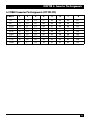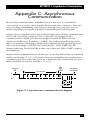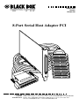
1
APRIL 2004
IC142C
IC190C-R2
8-Port Serial Host Adapter PCI
CUSTOMER
SUPPORT
INFORMATION
Order toll-free in the U.S.: Call 877-877-BBOX (outside U.S. call 724-746-5500)
FREE technical support 24 hours a day, 7 days a week: Call 724-746-5500 or fax 724-746-0746
Mailing address: Black Box Corporation, 1000 Park Drive, Lawrence, PA 15055-1018
Web site: www.blackbox.com • E-mail: [email protected]
FCC AND IC STATEMENTS/CE NOTICE
FEDERAL COMMUNICATIONS COMMISSION
AND
INDUSTRY CANADA
RADIO FREQUENCY INTERFERENCE STATEMENTS
This equipment generates, uses, and can radiate radio frequency energy and if not
installed and used properly, that is, in strict accordance with the manufacturer’s
instructions, may cause interference to radio communication. It has been tested
and found to comply with the limits for a Class A computing device in accordance
with the specifications in Subpart B of Part 15 of FCC rules, which are designed to
provide reasonable protection against such interference when the equipment is
operated in a commercial environment. Operation of this equipment in a
residential area is likely to cause interference, in which case the user at his own
expense will be required to take whatever measures may be necessary to correct
the interference.
Changes or modifications not expressly approved by the party responsible for
compliance could void the user’s authority to operate the equipment.
This digital apparatus does not exceed the Class A limits for radio noise emission from digital
apparatus set out in the Radio Interference Regulation of Industry Canada.
Le présent appareil numérique n’émet pas de bruits radioélectriques dépassant les limites
applicables aux appareils numériques de la classe A prescrites dans le Règlement sur le
brouillage radioélectrique publié par Industrie Canada.
EUROPEAN UNION DECLARATION OF CONFORMITY
This equipment complies with the requirements of the European EMC Directive
89/336/EEC.
1
8-PORT SERIAL HOST ADAPTER PCI
NORMAS OFICIALES MEXICANAS (NOM)
ELECTRICAL SAFETY STATEMENT
INSTRUCCIONES DE SEGURIDAD
1. Todas las instrucciones de seguridad y operación deberán ser leídas antes de
que el aparato eléctrico sea operado.
2. Las instrucciones de seguridad y operación deberán ser guardadas para
referencia futura.
3. Todas las advertencias en el aparato eléctrico y en sus instrucciones de
operación deben ser respetadas.
4. Todas las instrucciones de operación y uso deben ser seguidas.
5. El aparato eléctrico no deberá ser usado cerca del agua—por ejemplo, cerca
de la tina de baño, lavabo, sótano mojado o cerca de una alberca, etc..
6. El aparato eléctrico debe ser usado únicamente con carritos o pedestales que
sean recomendados por el fabricante.
7. El aparato eléctrico debe ser montado a la pared o al techo sólo como sea
recomendado por el fabricante.
8. Servicio—El usuario no debe intentar dar servicio al equipo eléctrico más allá
a lo descrito en las instrucciones de operación. Todo otro servicio deberá ser
referido a personal de servicio calificado.
9. El aparato eléctrico debe ser situado de tal manera que su posición no
interfiera su uso. La colocación del aparato eléctrico sobre una cama, sofá,
alfombra o superficie similar puede bloquea la ventilación, no se debe colocar
en libreros o gabinetes que impidan el flujo de aire por los orificios de
ventilación.
10. El equipo eléctrico deber ser situado fuera del alcance de fuentes de calor
como radiadores, registros de calor, estufas u otros aparatos (incluyendo
amplificadores) que producen calor.
2
NOM STATEMENT
11. El aparato eléctrico deberá ser connectado a una fuente de poder sólo del
tipo descrito en el instructivo de operación, o como se indique en el aparato.
12. Precaución debe ser tomada de tal manera que la tierra fisica y la polarización
del equipo no sea eliminada.
13. Los cables de la fuente de poder deben ser guiados de tal manera que no
sean pisados ni pellizcados por objetos colocados sobre o contra ellos,
poniendo particular atención a los contactos y receptáculos donde salen del
aparato.
14. El equipo eléctrico debe ser limpiado únicamente de acuerdo a las
recomendaciones del fabricante.
15. En caso de existir, una antena externa deberá ser localizada lejos de las lineas
de energia.
16. El cable de corriente deberá ser desconectado del cuando el equipo no sea
usado por un largo periodo de tiempo.
17. Cuidado debe ser tomado de tal manera que objectos liquidos no sean
derramados sobre la cubierta u orificios de ventilación.
18. Servicio por personal calificado deberá ser provisto cuando:
A: El cable de poder o el contacto ha sido dañado; u
B: Objectos han caído o líquido ha sido derramado dentro del aparato; o
C: El aparato ha sido expuesto a la lluvia; o
D: El aparato parece no operar normalmente o muestra un cambio en su
desempeño; o
E: El aparato ha sido tirado o su cubierta ha sido dañada.
3
8-PORT SERIAL HOST ADAPTER PCI
TRADEMARKS
AT, IBM, and OS/2 are registered trademarks of International Business Machines
Corporation.
Windows and Windows NT are either registered trademarks or trademarks of
Microsoft Corporation in the United States and/or other countries.
Any other trademarks mentioned in this manual are acknowledged to be the property
of the trademark owners.
4
CONTENTS
Contents
Chapter
Page
1. Specifications . . . . . . . . . . . . . . . . . . . . . . . . . . . . . . . . . . . . . . . . . . . . . . . . 6
2. Introduction . . . . . . . . . . . . . . . . . . . . . . . . . . . . . . . . . . . . . . . . . . . . . . . . . 7
2.1 Overview . . . . . . . . . . . . . . . . . . . . . . . . . . . . . . . . . . . . . . . . . . . . . . . . . 7
2.2 What’s Included . . . . . . . . . . . . . . . . . . . . . . . . . . . . . . . . . . . . . . . . . . . 7
3. Card Setup . . . . . . . . . . . . . . . . . . . . . . . . . . . . . . . . . . . . . . . . . . . . . . . . . . 8
3.1 Clock Modes . . . . . . . . . . . . . . . . . . . . . . . . . . . . . . . . . . . . . . . . . . . . . . 8
3.2 Baud Rates and Divisors for the “Div1” Mode . . . . . . . . . . . . . . . . . . . 9
3.3 Address and IRQ Selection . . . . . . . . . . . . . . . . . . . . . . . . . . . . . . . . . 10
4. Installation . . . . . . . . . . . . . . . . . . . . . . . . . . . . . . . . . . . . . . . . . . . . . . . . . 11
4.1 Setting Up the Operating System . . . . . . . . . . . . . . . . . . . . . . . . . . . . 11
4.1.1 Windows 3.1x . . . . . . . . . . . . . . . . . . . . . . . . . . . . . . . . . . . . . . . . 11
4.1.2 Windows 95/98 Users . . . . . . . . . . . . . . . . . . . . . . . . . . . . . . . . . 11
4.1.3 Windows NT. . . . . . . . . . . . . . . . . . . . . . . . . . . . . . . . . . . . . . . . . 11
4.1.4 DOS . . . . . . . . . . . . . . . . . . . . . . . . . . . . . . . . . . . . . . . . . . . . . . . 11
4.1.5 Other Operating Systems . . . . . . . . . . . . . . . . . . . . . . . . . . . . . . 11
4.2 Installing the Hardware . . . . . . . . . . . . . . . . . . . . . . . . . . . . . . . . . . . . 12
5. Technical Description . . . . . . . . . . . . . . . . . . . . . . . . . . . . . . . . . . . . . . . . 13
5.1 Interrupts . . . . . . . . . . . . . . . . . . . . . . . . . . . . . . . . . . . . . . . . . . . . . . . 13
5.2 Why Use an ISP? . . . . . . . . . . . . . . . . . . . . . . . . . . . . . . . . . . . . . . . . . . 13
6. Connector Pin Assignments . . . . . . . . . . . . . . . . . . . . . . . . . . . . . . . . . . . 14
6.1 DB25 (RS-232 DTE). . . . . . . . . . . . . . . . . . . . . . . . . . . . . . . . . . . . . . . 14
6.2 DB78 Connector Pin Assignments (IC142C). . . . . . . . . . . . . . . . . . . 14
6.3 DB68 Connector Pin Assignments (IC190C-R2) . . . . . . . . . . . . . . . . 15
Appendix A: Troubleshooting . . . . . . . . . . . . . . . . . . . . . . . . . . . . . . . . . . . 16
A.1 Using the Serial Utility CD-ROM . . . . . . . . . . . . . . . . . . . . . . . . . . . . 16
A.2 Calling Black Box. . . . . . . . . . . . . . . . . . . . . . . . . . . . . . . . . . . . . . . . . 17
A.3 Shipping and Packaging . . . . . . . . . . . . . . . . . . . . . . . . . . . . . . . . . . . 17
Appendix B: RS-232 Electrical Interface . . . . . . . . . . . . . . . . . . . . . . . . . . . 18
Appendix C: Asynchronous Communication . . . . . . . . . . . . . . . . . . . . . . . 19
5
8-PORT SERIAL HOST ADAPTER PCI
1. Specifications
Communications Chip: IC142C: 16554 UART; IC190C-R2: 16854 UART
Maximum Distance: 50 ft. (15.2 m)
Operation: RS-232
Protocol: Asynchronous
Speed: IC142C: Up to 460.8 kbps;
IC190C-R2: 460.8 kbps and above
CE Approval: Yes
Temperature: Operating: 32 to 122°F (0 to 50°C);
Storage: -4 to +158°F (-20 to +70°C)
Humidity: Up to 90% noncondensing
Connectors: IC142C: (1) DB78 male on card, (1) DB78 female and
(8) DB25 male on included octopus cable;
IC190C-R2: (1) DB68 female on card, (1) DB68 male and
(8) DB25 male on included octopus cable
Cable Length: 36" (91.4 cm)
Power: From the interface: IC142C: +5 V @ 250 mA;
IC190C-R2: Universal bus power +5V, +3.3 V
Size: IC142C: Half-card;
IC190C-R2: 2.5"H x 4.7"L (6.4 x 11.9 cm) including goldfingers,
2.2"H x 4.7"L (5.6 x 11.9 cm) excluding goldfingers
6
CHAPTER 2: Introduction
2. Introduction
2.1 Overview
The 8-Port Serial Host Adapter PCI provides the PC with eight RS-232
asynchronous ports. The adapter allows for connection to any device using the
RS-232 electrical interface, such as modems, data-entry terminals, and plotters.
The IC142C uses a 16554 UART, which features programmable baud rate, data
format, interrupt control, and a 16-byte input and output FIFO buffer. It’s
functionally four 16550 UARTs. The IC190C-R2 has a 16854 UART with a 128-byte
FIFO. It is functionally four 16850 UARTs.
2.2 What’s Included
The Serial Host Adapter PCI is shipped with the following items:
• 8-Port Serial Host Adapter PCI
• (1) DB78 female to (8) DB25 male octopus cable (IC142C) or
(1) DB68 male to (8) DB25 male octopus cable (IC190C-R2)
• (1) CD-ROM containing drivers, and this users’ manual in PDF format
If any of these items is missing or damaged, contact Black Box immediately
at 724-746-5500.
7
8-PORT SERIAL HOST ADAPTER PCI
3. Card Setup
3.1 Clock Modes
The adapter employs a unique clocking option that allows the end user to select
from divide-by-4 and divide-by-1 clocking modes. This mode is selected at J1.
DIV1
DIV4
To select the baud rates commonly associated with COM ports (2400, 4800, 9600,
19.2, … 115.2 kbps), place the jumper in the divide-by-4 position (marked DIV4).
Figure 3-1. Clocking mode “Divide By 4.”
DIV1
DIV4
To select the maximum data rate (460.8 kbps), place the jumper in the divideby-1 position (marked DIV1).
Figure 3-2. Clocking mode “Divide By 1.”
8
CHAPTER 3: Card Setup
3.2 Baud Rates and Divisors for the “Div1” Mode
The following table shows some common data rates and the rates you should
choose to match them if using the adapter in the “Div1” mode.
Table 3-1. Baud rates for the “Div1” mode.
For this Data Rate
1200 bps
2400 bps
4800 bps
9600 bps
19.2 kbps
57.6 kbps
115.2 kbps
230.4 kbps
460.8 kbps
Choose this Data Rate
300 bps
600 bps
1200 bps
2400 bps
4800 bps
14.4 kbps
28.8 kbps
57.6 kbps
115.2 kbps
If your communications package allows the use of baud-rate divisors, choose the
appropriate divisor from the following table:
Table 3-2. Baud-rate divisors for the “Div1” mode.
For this Data Rate
1200 bps
2400 bps
4800 bps
9600 bps
19.2 kbps
38.4 kbps
57.6 kbps
115.2 kbps
230.4 kbps
460.8 kbps
Choose this Divisor
384
192
96
48
24
12
8
4
2
1
9
8-PORT SERIAL HOST ADAPTER PCI
3.3 Address and IRQ Selection
The adapter is automatically assigned I/O addresses and IRQs by your
motherboard BIOS. Only the I/O address may be modified by the user.
Adding or removing other hardware may change the assignment of I/O addresses
and IRQs.
10
CHAPTER 4: Installation
4. Installation
IMPORTANT
You MUST set up the operating system BEFORE you physically install
the card.
4.1 Setting Up the Operating System
If you are installing the PCI adapter in DOS, OS/2®, or QNX, please refer to the
appropriate directory on the Serial Utilities CD-ROM for instructions.
4.1.1 WINDOWS 3.1X
Refer to the Win3x.hlp file in the \Win31 directory on the included CD-ROM.
4.1.2 WINDOWS 95/98 USERS
If you are installing the PCI card in Windows® 95/98, run setup on the CD-ROM
before installing the card. Power down the computer and install the adapter. The
resources are automatically configured for the PCI card. Refer to the appropriate
help file in the Black Box folder located in the Start, Programs menu for changing
those resources.
4.1.3 WINDOWS NT
If you are installing a PCI card in Windows NT®, run setup on the serial utilities
CD-ROM before installing the card. After the software installation is complete,
power down the computer, install the card, then power up. Since resource
allocation is automatic, the installation is now complete.
4.1.4 DOS
Refer to the Readme.txt file found in the \DOS directory on the serial utilities
CD-ROM.
4.1.5 OTHER OPERATING SYSTEMS
Refer to the appropriate directory on the serial utilities CD-ROM.
11
8-PORT SERIAL HOST ADAPTER PCI
4.2 Installing the Hardware
You can install the serial host adapter in any of the PCI expansion slots. It contains
several jumper straps for each port that you must set for proper operation (see
Chapter 3).
1. Power off the PC. Disconnect the power cord.
2. Remove the PC cover.
3. Locate an available PCI slot and remove the blank metal slot cover.
4. Gently insert the adapter into the slot. Make sure that it is seated properly.
5. Connect the DB78 female connector end of the octopus cable to the DB78
male connector on the card (IC142C) or connect the DB68 male connector
end of the octopus cable to the DB68 female connector on the card
(IC190C-R2).
6. Replace the screw.
7. Replace the cover.
8. Connect the power cord.
9. Once the card is installed in the PC, you can connect (8) RS-232 devices to
the (8) DB25 male connectors on the ends of the octopus cable.
12
CHAPTER 5: Technical Description
5. Technical Description
5.1 Interrupts
A good analogy of a PC interrupt is a telephone ringing. The phone bell is a
request for us to stop what we are currently doing and take up another task (speak
to the person on the other end of the line). This is the same process the PC uses to
alert the CPU that a task must be performed. The CPU, upon receiving an
interrupt, makes a record of what the processor was doing at the time and stores
this information on the “stack”; this allows the processor to resume its predefined
duties after the interrupt is handled, exactly where it left off. Every main sub-system
in the PC has its own interrupt, frequently called an IRQ (short for Interrupt
ReQuest).
5.2 Why Use an ISP?
The Interrupt Status Port (ISP) is a read-only 8-bit register that sets a
corresponding bit when an interrupt is pending. Port 1 interrupt line corresponds
with Bit D0 of the status port, Port 2 with D1, etc. The use of this port means that
the software designer now only has to poll a single port to determine if an
interrupt is pending.
The ISP is at Base+7 on each port (example: Base=280 hex, Status Port=287,
28F...etc.). The adapter will allow any one of the available locations to be read
to obtain the value in the status register. Both status ports on the adapter are
identical, so either one can be read. Example: This indicates that Channel 2 has
an interrupt pending.
Bit Position:
7
6
5
4
3
2
1
0
Value Read:
0
0
0
0
0
0
1
0
13
8-PORT SERIAL HOST ADAPTER PCI
6. Connector Pin Assignments
6.1 DB25 (RS-232 DTE)
Signal
GND
TD
RTS
DTR
RD
CTS
DSR
DCD
RI
Name
Pin #
Mode
Ground
Transmit Data
Request to Send
Data Terminal Ready
Receive Data
Clear to Send
Data Set Ready
Data Carrier Detect
Ring Indicator
7
2
4
20
3
5
6
8
22
—
Output
Output
Output
Input
Input
Input
Input
Input
6.2 DB78 Connector Pin Assignments (IC142C)
Port #
1
2
3
4
5
6
7
8
TD
RD
RTS
CTS
DTR
DSR
DCD
RI
GND
36
37
17
16
35
18
38
15
34
12
11
31
32
13
30
10
33
14
27
28
8
7
26
9
29
6
25
3
2
22
23
4
21
1
24
5
75
76
56
55
74
57
77
54
73
51
50
70
71
52
69
49
72
53
66
67
47
46
65
48
68
45
64
42
41
61
62
43
60
40
63
44
14
CHAPTER 6: Connector Pin Assignments
6.3 DB68 Connector Pin Assignments (IC190C-R2)
Port #
1
2
3
4
5
6
7
8
TD
RI
DCD
DTR
RTS
DSR
RD
CTS
GND
1
2
3
4
5
6
7
8
17
9
10
11
12
13
14
15
16
17
19
20
21
22
23
24
25
26
18
27
28
29
30
31
32
33
34
18
35
36
37
38
39
40
41
42
51
43
44
45
46
47
48
49
50
51
53
54
55
56
57
58
59
60
52
61
62
63
64
65
66
67
68
52
15
8-PORT SERIAL HOST ADAPTER PCI
Appendix A: Troubleshooting
A.1 Using the Serial Utility CD-ROM
A serial utility CD-ROM comes with the serial host adapter for use in
troubleshooting. If you still cannot solve a problem after reading this chapter,
call for technical support.
1. Identify all I/O adapters currently installed in your system, including your
on-board serial ports, controller cards, sound cards, etc. Identify the I/O
addresses used by these adapters, as well as the IRQ (if any).
2. Configure your serial host adapter so that there is no conflict with currently
installed adapters. No two adapters can occupy the same I/O address.
3. Make sure the adapter is using a unique IRQ. While this adapter does allow
the sharing of IRQs, many other adapters (such as SCSI adapters and onboard serial ports) do not. The IRQ is typically selected via an on-board
header block. Refer to Chapter 3 for help in choosing an I/O address
and IRQ.
4. Make sure the adapter is securely installed in a PCI slot.
5. For Windows 95/98/2000/Me/XP and Windows NT, the diagnostic tool
“WinSSD” is installed in the Adapter folder on the Start Menu during the
startup process. First find the ports using the Device Manager, then use
“WinSSD” to verify that the ports are working.
6. When running DOS, Windows 3.x or other operating systems, refer to the
serial utilities CD-ROM and this manual to verify that the adapter is
configured correctly. The supplied software contains a diagnostic program
“SSD” that runs under DOS and will verify if an adapter is configured
properly. This diagnostic program is easy to use. Refer to the README.txt file
on the supplied CD-ROM for detailed instructions on using “SSD.”
16
APPENDIX A: Troubleshooting
A.2 Calling Black Box
If the procedures described in Section A.1 do not solve your problem, call Black
Box Technical Support at 724-746-5500. Before you call, make a record of the
history of the problem.
We will be able to provide more efficient and accurate assistance if you have a
complete description, including:
• the nature and duration of the problem.
• when the problem occurs.
• the components involved in the problem.
• any particular application that, when used, appears to create the problem or
make it worse.
Also, have the following information ready when you call:
1. Current adapter settings. If possible, have the adapter installed in a computer
ready to run diagnostics.
2. This user manual (on CD-ROM) for reference.
A.3 Shipping and Packaging
If you need to transport or ship your 8-Port Serial Host Adapter PCI:
• Package it carefully. We recommend that you use the original container.
• If you are shipping the adapter for repair, make sure you include everything
that came in the original package. Before you ship, contact Black Box to get a
Return Authorization (RA) number.
17
8-PORT SERIAL HOST ADAPTER PCI
Appendix B: RS-232 Electrical
Interface
The most widely used communication standard is RS-232. It’s been defined and
revised several times and is sometimes also called EIA/TIA-232. The IBM® AT®
computer defined the RS-232 port on a DB9 connector, and subsequently the
EIA/TIA approved this implementation as the EIA/TIA-574 standard, which is
defined as the “9-Position Non-Synchronous Interface between Data Terminal
Equipment and Data Circuit-Terminating Equipment Employing Serial Binary
Data Interchange.”
RS-232 can operate at data rates of up to 20 kbps at distances less than 50 ft.
(15.2 m). The absolute maximum data rate may vary depending on line conditions
and cable lengths. RS-232 is a single-ended or unbalanced interface, meaning that
a single electrical signal is compared to a common signal (ground) to determine
binary logical states. The RS-232 and the EIA/TIA-574 specification define two
types of interface circuits, Data Terminal Equipment (DTE) and Data CircuitTerminating Equipment (DCE). The serial host adapter is a DTE device.
18
APPENDIX C: Asynchronous Communication
Appendix C: Asynchronous
Communication
In serial data communication, individual bits of a character are transmitted
consecutively to a receiver that assembles the bits back into a character. Data rate,
error checking, handshaking, and character framing (start/stop bits) are predefined and must correspond at both the transmitting and receiving ends.
Asynchronous communication is the standard means of serial data communication
for PC and compatible computers. The original PC was equipped with a
communication or COM port that was designed around an 8250 Universal
Asynchronous Receiver Transmitter (UART), which allows asynchronous serial
data to be transferred through a simple and straightforward programming device.
The serial host adapter (IC142C) uses a much newer 16554 UART that also
features buffering. The IC190C-R2 features an even newer 16854 UART complete
with buffering.
Asynchronous communication works this way: A start bit, followed by a pre-defined
number of data bits (5, 6, 7, or 8) defines character boundaries for asynchronous
communication. The end of the character is defined by the transmission of a predefined number of stop bits (usually 1, 1.5, or 2).
Idle State
of
Line
5 to 8 Data Bits
Odd
Even
or
Unused
Remain Idle
or
Next Start Bit
1
Parity
Bit
0
1
1.5
2
Stop Bits
Figure C-1. Asynchronous communication bit diagram.
19
8-PORT SERIAL HOST ADAPTER PCI
An extra bit used for error detection is often appended before the stop bits.
This special bit is called the parity bit. Parity is a simple way to determine if a data
bit has been lost or corrupted during transmission. There are several methods for
implementing a parity check to guard against data corruption. Common methods
are called [E]ven Parity or [O]dd Parity. Sometimes parity is not used to detect
errors on the data stream (this is called [N]o Parity). Because each bit in
asynchronous communication is sent consecutively, it is wrapped (framed) by
pre-defined bits to mark the beginning and end of the serial transmission of the
character. The data rate and communication parameters for asynchronous
communication have to be the same at both the transmitting and receiving ends.
The communication parameters are baud rate, parity, number of data bits per
character, and stop bits—for example, 9600, N, 8, 1.
20
© Copyright 2004. Black Box Corporation. All rights reserved.
1000 Park Drive • Lawrence, PA 15055-1018 • 724-746-5500 • Fax 724-746-0746