1
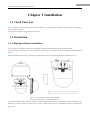
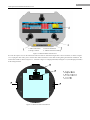
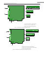
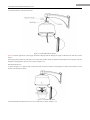
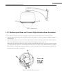
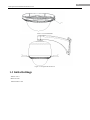
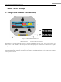
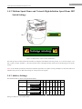
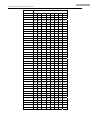
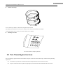
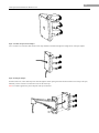
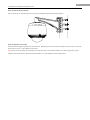
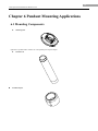
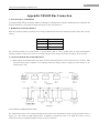
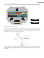
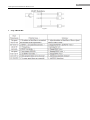
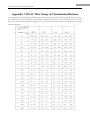
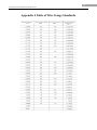
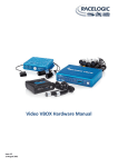
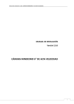
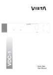
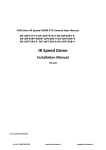
6 Inch Speed Dome Installation Manual V2.0.0 2010-01 1 6 Inch Speed Dome Installation Manual V2.0.0 Thank you for purchasing our product. If there is any question or request, please do not hesitate to contact dealer. This manual is applicable to 6 Inch Speed Dome. This manual may contain several technically incorrect places or printing errors, and the content is subject to change without notice. The updates will be added into the new version of this manual. We will readily improve or update the products or procedures described in the manual. 2 6 Inch Speed Dome Installation Manual V2.0.0 Safety Instruction These instructions are intended to ensure that user can use the product correctly to avoid danger or property loss. The precaution measure is divided into “Warnings” and “Cautions”: Warnings: Neglecting any of the warnings may cause serious injury or death. Cautions: Neglecting any of the cautions may cause injury or equipment damage. Warnings Follow these safeguards to prevent serious injury or death. Cautions Follow these precautions to prevent potential injury or material damage. Warnings 1. In the use of the product, you must be strict compliance with the electrical safety regulations of the nation and region. 2. Please use the power adapter, which is provided by normal company. The standard of the power adapter is AC24V/3A. 3. Do not connect several devices to one power adapter as adapter overload may cause over-heat or fire hazard. 4. Please make sure that the plug is firmly connected on the power socket. 5. When the product is installed on wall or ceiling, the device shall be firmly fixed. 6. If smoke, odors or noise rise from the device, turn off the power at once and unplug the power cable, and then please contact the service center. 7. If the product does not work properly, please contact your dealer or the nearest service center. Never attempt to disassemble the camera yourself. (We shall not assume any responsibility for problems caused by unauthorized repair or maintenance.) Warnings 1. Do not drop the dome or subject it to physical shock, and do not expose it to high electromagnetism radiation. Avoid the equipment installation on vibrations surface or places subject to shock (ignorance can cause equipment damage). 2. Do not place the dome in extremely hot, cold (the operating temperature shall be -30°C ~ +65°C), dusty or damp locations, or fire or electrical shock will occur otherwise. 3. The dome cover for indoor use shall be kept from rain and moisture. 4. Exposing the equipment to direct sun light, low ventilation or heat source such as heater or radiator is forbidden (ignorance can cause fire danger). 5. Do not aim the camera at the sun or extra bright places. A blooming or smear may occur otherwise (which is not a malfunction however), and affecting the endurance of CCD at the same time. 6. Please use the provided glove when open up the dome cover, avoid direct contact with the dome cover, because the acidic sweat of the fingers may erode the surface coating of the dome cover. 7. Please use a soft and dry cloth when clean inside and outside surfaces of the dome cover, not to use alkaline detergents. 3 6 Inch Speed Dome Installation Manual V2.0.0 Preparation for Installation 1. Basic requirements 1) All the electronic operation should be strict compliance with the local electrical safety regulations, fire prevention regulations and other related regulations at the installation place. 2) Check whether all the accessories are there according to the packing list, make sure that the place and installation mode are conform to the demands, if not, please contact the supplier. 3) 2. Please use this product according to the working environment. Check installation space. Make sure the place have enough space to install the speed domes and its accessories. 3. Check the intensity of conformation at the installation scene. Please make sure that the endure ability of ceilings or walls is 4 times as the weight of speed dome and its accessories. 4. Preparation of cables z 5. Choose the video cable according to the transmission length. The video should meet the least demands as: 1. 75Ω resistance 2. 100% copper core conducting wire. 3. 95% weaving copper shield. z RS485 communication cable, please refer to Appendix 2 z 24V AC power cable, please refer to Appendix 3 Please keep all wrappers Please keep all wrappers after unpack them for future use. In case of any failure occurred, please return the speed dome to the factory with the original wrapper. Note: Transportation without the original wrapper may result in damage on the speed dome and cost additional charge. 4 6 Inch Speed Dome Installation Manual V2.0.0 Table of Contents Table of Contents......................................................................................................................................................... 4 Chapter 1 Installation................................................................................................................................................... 6 1.1 Check Parts List............................................................................................................................................. 6 1.2 Installation ..................................................................................................................................................... 6 1.2.1 High Speed Dome Installation ..................................................................................................... 6 1.2.2 Medium Speed Dome and Network High-definition Dome Installation ................................... 10 1.3 Initial Settings.............................................................................................................................................. 15 1.4 DIP Switch Settings ..................................................................................................................................... 16 1.4.1 High Speed Dome DIP Switch Settings..................................................................................... 16 1.4.2 Medium Speed Dome and Network High-definition Speed Dome DIP Switch Settings .......... 17 1.4.3 Address Settings ........................................................................................................................ 17 1.4.4 Baud Rate Settings..................................................................................................................... 20 1.4.5 Protocol Settings (High Speed Dome) ....................................................................................... 20 1.4.6 Parity and Manchester Code Settings (Medium Speed Dome & Network Speed Dome) ......... 20 1.4.7 Simplex/Half-duplex Settings.................................................................................................... 20 1.4.8 Terminating Resistor Settings .................................................................................................... 21 1.5 Alarm In/Out Connections........................................................................................................................... 21 Chapter 2 Mounts Dimension .................................................................................................................................... 22 2.1 Long-arm Wall Mount ................................................................................................................................. 22 2.2 Short-arm Wall Mount ................................................................................................................................. 23 2.3 Corner Adapter............................................................................................................................................. 23 2.4 Pole Adapter................................................................................................................................................. 24 2.5 Pendant Adapter........................................................................................................................................... 24 Chapter 3 Wall Mounting Applications ..................................................................................................................... 25 3.1 Mounting Components ................................................................................................................................ 25 3.2 Wall Mounting Instructions ......................................................................................................................... 25 Chapter 4 Corner Mounting Applications.................................................................................................................. 28 4.1 Mounting Components ................................................................................................................................ 28 4.2 Corner Mounting Instructions...................................................................................................................... 29 Chapter 5 Pole Mounting Applications...................................................................................................................... 31 5.1 Mounting Components ................................................................................................................................ 31 5.2 Pole Mounting Instructions.......................................................................................................................... 32 Chapter 6 Pendant Mounting Applications ................................................................................................................ 35 6.1 Mounting Components ................................................................................................................................ 35 6.2 Pendant Mounting Instructions.................................................................................................................... 36 Chapter 7 In-ceiling Mounting Applications ............................................................................................................. 38 7.1 Installation Conditions................................................................................................................................. 38 7.2 In-ceiling Mounting Instructions ................................................................................................................. 38 Appendix 1 Lightning & Surge Protection ................................................................................................................ 43 Appendix 2 RS485 Bus Connection .......................................................................................................................... 44 Appendix 3 24VAC Wire Gauge & Transmission Distance ...................................................................................... 47 5 6 Inch Speed Dome Installation Manual V2.0.0 Appendix 4 Table of Wire Gauge Standards.............................................................................................................. 48 6 6 Inch Speed Dome Installation Manual V2.0.0 Chapter 1 Installation 1.1 Check Parts List Prior to installation, unpack the dome unit and check whether it is in good condition and all parts and accessories are included by referring to the packing list). Note: The power supply for the speed dome is 24VAC/3A. 1.2 Installation 1.2.1 High Speed Dome Installation Note: The following installation instructions are applicable to both high speed dome and network speed dome models. 1. Install the dome mount. Please refer to the related sections from Chapter2 to Chapter7 for specific installation methods of different mounts. 2. Open the bubble and remove the expand aple poly ethylene and protective sticker from the dome drive. Refer to Figure 1.2.1. Figure 1.2.1 Open bubble and remove the expand aple poly ethylene and protective sticker from dome drive 3. Configure the dome address, baud rate and other settings through DIP switch SW1 and SW2 located on the bottom board of the dome drive, as shown in Figure 1.2.2. Please refer to Section 1.4 DIP Switch Settings for setting address, baud rate, communication protocol, etc. 7 6 Inch Speed Dome Installation Manual V2.0.0 1. Address DIP Switch 2. Protocol DIP Switch 3. Wiring Connector 4. Address and Protocol Settings Figure 1.2.2 Bottom Board of Dome Drive 4. Loosen the captive screw on the interconnect board of back box and lift the hinged door to the circuit board, as shown in Figure 1.2.3. Unplug the video cable, power cord and other cables terminals to avoid cables twisting during the back box installation. The circuit board of dome is shown in Figure 1.2.3. And refer to Figure 1.2.4 (high speed dome) and Figure 1.2.5(network high speed dome) for the wiring terminals. Figure 1.2.3 Back Box Interconnect Board 8 6 Inch Speed Dome Installation Manual V2.0.0 1: Alarm In/Out Terminals (7 inputs/2outputs) 2: Video Out and RS-485 COM Terminals 3: 24VAC Voltage Input and GND Terminals Figure 1.2.4 Back Box Circuit Board (High Speed Dome) 1: Alarm In/Out Terminals (2 inputs/2 outputs) 2: Audio In/Out, Video Out and RS-485 COM Terminals 3: 24VAC Voltage Input and GND Figure 1.2.5 Back Box Circuit Board (Network High Speed Dome) \ 9 6 Inch Speed Dome Installation Manual V2.0.0 5. Attach the back box of dome to the mount. Figure 1.2.6 Attach Back Box to Mount Note: For outdoor applications, please apply the thread compound and the damp-proof stopper to threads of the back box and the mount. After having made connections of the power cord, video cable, RS-485 control line and alarm input/output lines (if required), close the hinged door and tighten the captive screw, as shown in Figure 1.2.6. 6. Install the dome drive As shown in Figure 1.2.7, align the tabs on both sides of the dome drive with the corresponding arrow labels on the back box to snap the drive into the back box firmly. Figure 1.2.7 Install Dome Drive 7. Install the bubble and fasten the two set screws on both sides, as shown in Figure 1.2.8. 10 6 Inch Speed Dome Installation Manual V2.0.0 Figure 1.2.8 Install Bubble 1.2.2 Medium Speed Dome and Network High-definition Dome Installation Note: The following installation instructions are applicable to both medium speed dome and HD network speed dome models. 1. Install the dome mounts. Please refer to the related sections from Chapter2 to Chapter7 for specific installation methods of different mounts. 2. Open the bubble, push the two clips on both sides of the dome drive towards the back box, and then take off the dome drive. Remove the expand aple poly ethylene and protective sticker from the dome drive. Refer to Figure 1.2.9. Push the tab lock on the bottom interconnect board of back box and lift the hinged door to the circuit board, as shown in Figure 1.2.9. Unplug the video cable, power cord and other cables terminals to avoid cables twisting during the back box installation. Refer to Figure 1.2.10 (medium speed dome) and Figure1.2.11 (network speed dome and network high-definition speed dome) for the wiring terminals on back box circuit board. Figure 1.2.9 Back Box Interconnect Board 11 6 Inch Speed Dome Installation Manual V2.0.0 1: Video Out and RS-485 COM Terminals 2: 24VAC Voltage Input and GND Terminals Figure 1.2.10 Back Box Circuit Board (Medium Speed Dome) MIC SPK GND IN1 OUT1 COM NC1 NC2 VOUT VGND Rx+ Rx- 1: Video Out and RS-485 COM Terminals 2: Audio In/Out, Alarm In/Out Terminals and GND(1 inputs/1outputs) 3: 24VAC Voltage Input and GND Terminals Figure 1.2.11 Back Box Circuit Board (Network Medium Speed Dome and Network High-definition Speed Dome) 3. Configure the dome address, baud rate and other settings through DIP switch SW1 and SW2 located on the bottom board of the dome, as shown in Figure 1.2.2. Please refer to Section 1.4 DIP Switch Settings for setting address, baud rate, communication 12 6 Inch Speed Dome Installation Manual V2.0.0 protocol, etc. Figure 1.2.12 Address and Protocol Settings Key lock Figure1.2.13 DIP Switch Location on Side of Dome Drive 4. Install the back box. Open the interconnect board of the back box, and feed the cables through the top of the back box from the mount, and connect to the back board circuit board. Attach the back box to the mount and tighten the set screws (see Figure1.2.14) to secure the back box. Connect all wiring and replace the interconnect board. Note: For outdoor applications, please apply the thread compound and the damp-proof stopper to threads of the back box and the mount. 13 6 Inch Speed Dome Installation Manual V2.0.0 Figure 1.2.14 Attach Back Box to Mount 5. Install the dome drive. Push the two tabs on both sides of the dome drive, and line up the AMP connectors to insert the dome drive into the back box by following the guided pillar. Continue pushing on the both ends of the tabs until both sides click firmly into place. Figure 1.2.15 Install Dome Drive 14 6 Inch Speed Dome Installation Manual V2.0.0 G u id ed Pil lar A M P Co n n ecto r Bo tt o m Bo ard an d Set Screw s Figure 1.2.16 AMP Connector and Guided Pillar on Interconnect Board AM P Co n n ecto r Gu id ed Arc Figure 1.2.17 AMP Connector and Guided Arc on Dome Drive Bottom Board 6. Install the bubble by aligning the two grooves (see Figure 1.2.18) on the trim ring of the bubble with the two set screws (see Figure 1.2.19) on the back box, and then fasten the set screws to secure the bubble. 15 6 Inch Speed Dome Installation Manual V2.0.0 Cl ip Figure 1.2.18 Install Bubble Figure 1.2.19 Tighten the Set Screws 1.3 Initial Settings Address code: 0 Baud rate: 2400 120Ω terminator: OFF 16 6 Inch Speed Dome Installation Manual V2.0.0 1.4 DIP Switch Settings 1.4.1 High Speed Dome DIP Switch Settings Figure 1.4.2 Bottom Board of Dome Drive 1. Address DIP Switch 2. Protocol DIP Switch 3. Wiring Connector 4. Address and Protocol Settings The dome provides two DIP switches SW1 and SW2 for setting the dome address, baud rate, protocol, etc. As shown in Figure 1.4.2, ON=1, OFF=0. In SW1 and SW2, 1 is the lowest position and 8 is the highest position. Please refer to the following list for specific settings: Note: As the high speed dome is capable of being self-adaptive to PELCO-D, PELCO-P, HIK-Code, VICON and KALATEL-32 protocols, and the network speed dome is self-adaptive to Pelco-P, Pelco-D and HIK-Code protocols as well, no DIP switch settings for control protocol are required. 17 6 Inch Speed Dome Installation Manual V2.0.0 1.4.2 Medium Speed Dome and Network High-definition Speed Dome DIP Switch Settings 1: SW1 Address DIP Switch 2: SW2 Protocol DIP Switch Figure1.4.3 DIP Switch Location on Side of Dome Drive The dome provides two DIP switches SW1 and SW2 for setting the dome address, baud rate, protocol, etc. As shown in Figure 1.4.2, ON=1, OFF=0. In SW1 and SW2, 1 is the lowest position and 8 is the highest position. Please refer to the following list for specific settings: Note: As the medium speed dome and the network medium speed dome are capable of being self-adaptive to PELCO-D, PELCO-P and HIK-Code protocols, no DIP switch settings for control protocol are required. 1.4.3 Address Settings The DIP Switch SW1 is used for setting the dome address: Dome Address SW1 Settings 1 2 3 4 5 6 7 8 0 OFF OFF OFF OFF OFF OFF OFF OFF 1 ON OFF OFF OFF OFF OFF OFF OFF 255 ON ON ON ON ON ON ON ON Settings for address 0~71 are listed as below: 18 6 Inch Speed Dome Installation Manual V2.0.0 SW1 Position DIP Switch SW1 Settings Address 1 2 3 4 5 6 7 8 0 OFF OFF OFF OFF OFF OFF OFF OFF 1 ON OFF OFF OFF OFF OFF OFF OFF 2 OFF ON OFF OFF OFF OFF OFF OFF 3 ON ON OFF OFF OFF OFF OFF OFF 4 OFF OFF ON OFF OFF OFF OFF OFF 5 ON OFF ON OFF OFF OFF OFF OFF 6 OFF ON ON OFF OFF OFF OFF OFF 7 ON ON ON OFF OFF OFF OFF OFF 8 OFF OFF OFF ON OFF OFF OFF OFF 9 ON OFF OFF ON OFF OFF OFF OFF 10 OFF ON OFF ON OFF OFF OFF OFF 11 ON ON OFF ON OFF OFF OFF OFF 12 OFF OFF ON ON OFF OFF OFF OFF 13 ON OFF ON ON OFF OFF OFF OFF 14 OFF ON ON ON OFF OFF OFF OFF 15 ON ON ON ON OFF OFF OFF OFF 16 OFF OFF OFF OFF ON OFF OFF OFF 17 ON OFF OFF OFF ON OFF OFF OFF 18 OFF ON OFF OFF ON OFF OFF OFF 19 ON ON OFF OFF ON OFF OFF OFF 20 OFF OFF ON OFF ON OFF OFF OFF 21 ON OFF ON OFF ON OFF OFF OFF 22 OFF ON ON OFF ON OFF OFF OFF 23 ON ON ON OFF ON OFF OFF OFF 24 OFF OFF OFF ON ON OFF OFF OFF 25 ON OFF OFF ON ON OFF OFF OFF 26 OFF ON OFF ON ON OFF OFF OFF 27 ON ON OFF ON ON OFF OFF OFF 28 OFF OFF ON ON ON OFF OFF OFF 29 ON OFF ON ON ON OFF OFF OFF 30 OFF ON ON ON ON OFF OFF OFF 31 ON ON ON ON ON OFF OFF OFF 32 OFF OFF OFF OFF OFF ON OFF OFF 33 ON OFF OFF OFF OFF ON OFF OFF 34 OFF ON OFF OFF OFF ON OFF OFF 35 ON ON OFF OFF OFF ON OFF OFF 36 OFF OFF ON OFF OFF ON OFF OFF 37 ON OFF ON OFF OFF ON OFF OFF 38 OFF ON ON OFF OFF ON OFF OFF 39 ON ON ON OFF OFF ON OFF OFF 40 OFF OFF OFF ON OFF ON OFF OFF 19 6 Inch Speed Dome Installation Manual V2.0.0 41 ON OFF OFF ON OFF ON OFF OFF 42 OFF ON OFF ON OFF ON OFF OFF 43 ON ON OFF ON OFF ON OFF OFF 44 OFF OFF ON ON OFF ON OFF OFF 45 ON OFF ON ON OFF ON OFF OFF 46 OFF ON ON ON OFF ON OFF OFF 47 ON ON ON ON OFF ON OFF OFF 48 OFF OFF OFF OFF ON ON OFF OFF 49 ON OFF OFF OFF ON ON OFF OFF 50 OFF ON OFF OFF ON ON OFF OFF 51 ON ON OFF OFF ON ON OFF OFF 52 OFF OFF ON OFF ON ON OFF OFF 53 ON OFF ON OFF ON ON OFF OFF 54 OFF ON ON OFF ON ON OFF OFF 55 ON ON ON OFF ON ON OFF OFF 56 OFF OFF OFF ON ON ON OFF OFF 57 ON OFF OFF ON ON ON OFF OFF 58 OFF ON OFF ON ON ON OFF OFF 59 ON ON OFF ON ON ON OFF OFF 60 OFF OFF ON ON ON ON OFF OFF 61 ON OFF ON ON ON ON OFF OFF 62 OFF ON ON ON ON ON OFF OFF 63 ON ON ON ON ON ON OFF OFF 64 OFF OFF OFF OFF OFF OFF ON OFF 65 ON OFF OFF OFF OFF OFF ON OFF 66 OFF ON OFF OFF OFF OFF ON OFF 67 ON ON OFF OFF OFF OFF ON OFF 68 OFF OFF ON OFF OFF OFF ON OFF 69 ON OFF ON OFF OFF OFF ON OFF 70 OFF ON ON OFF OFF OFF ON OFF 71 ON ON ON OFF OFF OFF ON OFF 20 6 Inch Speed Dome Installation Manual V2.0.0 1.4.4 Baud Rate Settings The positions 1-3 of DIP Switch SW2 are used for setting the baud rate of dome, respectively as 2400bps, 4800bps, 9600bps, 19200bps and 38400bps. For baud rate out of the above range, the default setting is 2400bps. Refer to the following table: DIP Switch SW2-Baud Rate Settings Baud Rate Positions1-3 Settings 1 2 3 2400 ON OFF OFF 4800 OFF ON OFF 9600 ON ON OFF 19200 OFF OFF ON 38400 ON OFF ON 1.4.5 Protocol Settings (High Speed Dome) The positions 4-6 of DIP Switch SW2 are used for setting the communication protocols of dome. Refer to the following table (network speed dome model does not support Manchester code protocol): DIP Switch SW2-Protocol Settings Protocol Positions 4-6 Settings 4 5 6 Bosch Manchester OFF ON ON AD Manchester ON ON ON Self-adaptive Others 1.4.6 Parity and Manchester Code Settings (Medium Speed Dome & Network Speed Dome) SW2 中的开关 4、5、6 用来选择智能球奇偶校验和曼码协议,以下是具体通讯协议对应的拨码方式(网络智能球不支持 曼码协议): The positions 4-6 of DIP Switch SW2 are used for setting the parity and Manchester protocol of dome. Refer to the following table (network speed dome model does not support Manchester code protocol): SW2-Parity and Manchester Code Settings Parity/Manchester Positions 4-6 Settings 4 5 6 None OFF OFF OFF Odd ON OFF OFF Even OFF ON OFF Manchester ON ON ON 1.4.7 Simplex/Half-duplex Settings The position 7 of DIP Switch SW2 is used for setting the communication method of dome to simplex or half-duplex. DIP Switch SW2-Simplex/Half-duplex Settings Description Position 7 Setting 7 21 6 Inch Speed Dome Installation Manual V2.0.0 Simplex OFF Half-duplex ON 1.4.8 Terminating Resistor Settings The position 8 of DIP Switch SW2 is used for setting the terminating resistor of dome. DIP Switch SW2-Terminating Resistor Settings Description Position 8 Setting Not Terminated Terminated 8 OFF ON 1.5 Alarm In/Out Connections Note: The Medium Speed Dome have no alarm inputs and alarm outputs. The high speed dome can be connected with 7 alarm inputs (0~12VDC) and 2 alarm outputs; and the network high speed dome is allowed to connect with 2 alarm inputs (0~12VDC) and 2 alarm outputs; and the network medium speed dome and the HD network speed dome is allowed to connect with 1 alarm inputs (0~12VDC) and 1 alarm outputs . Refer to the following diagram: The alarm provides the relay output (no voltage), and the external power supply is required when it connects to the alarm device. For DC power supply (left diagram), the input voltage must be within the range of 12VDC, 30mA. For AC power supply, the external relay must be used (right diagram) so as to prevent damages to the unit and avoid risk of electric shock. 22 6 Inch Speed Dome Installation Manual V2.0.0 Chapter 2 Mounts Dimension 2.1 Long-arm Wall Mount St u d St u d 23 6 Inch Speed Dome Installation Manual V2.0.0 2.2 Short-arm Wall Mount S tu d 2.3 Corner Adapter Stud Stud 24 6 Inch Speed Dome Installation Manual V2.0.0 2.4 Pole Adapter Stud 2.5 Pendant Adapter 25 6 Inch Speed Dome Installation Manual V2.0.0 Chapter 3 Wall Mounting Applications 3.1 Mounting Components z Wall Mount Applicable to indoor/outdoor pendant domes. Or z Mounting Accessories Nuts and Flat Washers 3.2 Wall Mounting Instructions The wall mounting is applicable to the indoor/outdoor solid wall construction which should comply with the following mounting requirements: z The wall must be thick enough to install the expansion screws. z The wall must be capable of supporting up to 8 times the total load of the dome and its accessories. 26 6 Inch Speed Dome Installation Manual V2.0.0 Step1: Drill mounting holes in the wall and install the expansion screws Drill four holes in the wall according to the mounting locations, and then insert M6 expansion screws (not supplied) into the mounting holes. Step2: Secure the wall mount to the wall Fasten the expansion screws through the wall mount and gasket by using four hex nuts with flat washers to secure the wall mount to the wall. 27 6 Inch Speed Dome Installation Manual V2.0.0 Step3: Install dome to the mount Feed cables through the opening on top of the back box, screw the back box into the threads in the mount, and then use M3 screws to secure the dome. Refer to Section 1.2 for installation instructions. Note: Follow the same instructions described above for the Short-arm Wall Mount installation. For outdoor applications, please adopt the water-proof measures. The Short-arm Wall Mount is not recommended for outdoor applications. 28 6 Inch Speed Dome Installation Manual V2.0.0 Chapter 4 Corner Mounting Applications 4.1 Mounting Components z Wall Mount Applicable to the indoor/outdoor pendant domes with the use of corner adapter, wall adapter or pole adapter. z Corner Adapter For use with the wall mount in the corner mounting applications. Mounting Accessories Hex Screws (M8×30), Nuts, Spring Washers and Flat Washers 29 6 Inch Speed Dome Installation Manual V2.0.0 4.2 Corner Mounting Instructions The corner mounting is applicable to the indoor/outdoor 90° solid corner construction which should comply with the following mounting requirements: z The wall must be thick enough to install the expansion screws. z The wall must be capable of supporting up to 8 times the total load of the dome and its accessories. Step1: Install the corner adapter Drill four holes in the corner according to the mounting locations, and then insert M6 expansion screws (not supplied) into the holes. Pull the power cord, video cable and control line through the opening of the corner adapter. Secure the corner adapter to the corner by using nuts and washers to tighten the four expansion screws. Note: Make sure the cables have enough length. For outdoor applications, please apply the sealant around the cable opening to prevent water. Step2: Secure the wall mount to the corner Apply four hex screws with the spring washers to the corner adapter through the wall mount and gasket. Note: When tightening the screw, it is better to compress the spring washer firstly and then rotate half a round so as to maintain required waterproof effect without damaging the threads. 30 6 Inch Speed Dome Installation Manual V2.0.0 Step3: Install dome to the mount Feed the cables through the opening on top of the back box, and attach the dome to the mount. Finally, use M3 screws to secure the two units. Refer to Section 1.2 for installation instructions. Note: Follow the same instructions described above for the Short-arm Corner Mount installation. For outdoor applications, please adopt the water-proof measures. The Short-arm Wall Mount is not recommended for outdoor applications. 31 6 Inch Speed Dome Installation Manual V2.0.0 Chapter 5 Pole Mounting Applications 5.1 Mounting Components z Wall Mount Applicable to indoor/outdoor pendant domes with the use of corner adapter, wall adapter or pole adapter. z Pole Adapter For use with the wall mount in the pole mounting applications. 32 6 Inch Speed Dome Installation Manual V2.0.0 z Stainless Steel Straps For use with the pole adapter, with the following dimensions selectable: φ59-82mm, φ84-108mm, φ103-127mm, φ130-152mm, φ155-178mm, φ180-203mm, φ194-216mm; Customized dimensions can also be provided according to user’s demand. z Mounting Accessories Hex Screws (M8×30) and Spring Washers 5.2 Pole Mounting Instructions The pole mounting is applicable to the indoor/outdoor solid pole construction which should comply with the following mounting requirements: z The diameter of pole must be constituent with the mounting dimensions of the stainless steel straps. z The pole construction must be capable of supporting up to 8 times the total load of the dome and its accessories. 33 6 Inch Speed Dome Installation Manual V2.0.0 Step1: Assemble the pole mount adapter Use a screwdriver to loosen the three stainless steel straps and then insert them through the rectangle holes on the pole adapter. Step2: Install pole adapter Feed the control line, video cable and power cable through the central opening and secure the three stainless steel straps to the pole, and finally use the screwdriver to fasten the screws at the steel straps. Note: For outdoor applications, please adopt the water-proof measures. 34 6 Inch Speed Dome Installation Manual V2.0.0 Step3: Install wall mount assembly Screw four hex screws with the spring washers to the pole adapter through the wall mount and gasket. Step4: Install dome to the mount Feed the cables through the opening on top of the back box, and attach the dome to the mount, and finally use M3 screws to secure the dome. Refer to Section 1.2 for installation instructions. Note: Follow the same instructions described above for the Short-arm Corner Mount installation. For outdoor applications, please adopt the water-proof measures. The Short-arm Wall Mount is not recommended for outdoor applications. 35 6 Inch Speed Dome Installation Manual V2.0.0 Chapter 6 Pendant Mounting Applications 6.1 Mounting Components z Mounting Base Applicable to pendant domes with the use of the pendant pole and pole adapter. z Pendant Pole Pendant Adapter 36 6 Inch Speed Dome Installation Manual V2.0.0 6.2 Pendant Mounting Instructions The pendant mounting is applicable to the indoor/outdoor solid ceiling construction which should comply with the following mounting requirements: z The ceiling must be thick enough to mount the expansion screws. z The ceiling must be capable of supporting up to 8 times the total load of the dome and its accessories. Step1: Install the mounting base Drill four φ6 holes in the ceiling according to the fastener holes locations of the mounting base, and then insert M6 expansion screws (not supplied) into the holes. Pull the power cord, video cable and control line through the opening at the mounting base. Secure the mounting base to the corner by using nuts and washers to tighten the four expansion screws. Note: Make sure the cables have enough length. For outdoor applications, please apply water-proof measures between the ceiling surface and mounting base and around the cables opening. The pendant mounting application is not recommended for outdoor environment where directly suffers rain. 37 6 Inch Speed Dome Installation Manual V2.0.0 Step2: Install the pendant pole Swivel the pendant adapter into the matching pendant pole and then use the retainer screws to secure the two parts. Pull out the cables through the pendant pole and screw the pendant pole into the mounting base and use the set screws to secure the two parts as well. Note: For outdoor applications, please apply the water-proof thread compound to the threads. Step3: Install dome to the mount Feed the cables through the opening on top of the back box, and attach the dome to the pendant pole, and finally use M3 screws to secure the dome. Refer to Section 1.2 for installation instructions. Note: In case of insufficient ceiling height, directly attach the dome to the mounting base without use of pendant pole, as shown in the figure right above. 38 6 Inch Speed Dome Installation Manual V2.0.0 Chapter 7 In-ceiling Mounting Applications 7.1 Installation Conditions The in-ceiling mounting is applicable to the indoor ceiling construction which should comply with the following mounting requirements: z The height above the ceiling must be more than 250mm. z The ceiling must be with the thickness of 5~40mm. z The ceiling must be capable of supporting up to 5 times the total load of the dome and its accessories. 7.2 In-ceiling Mounting Instructions Step1: Drill holes in the ceiling Take out the drill drawing from the package and use it as a template to draw a circle on the ceiling and then cut out the circle. Note: The allowable tolerance of diameter is 2mm. Drill Drawing 39 6 Inch Speed Dome Installation Manual V2.0.0 Step2: Connect cables Open the hinged door and feed the power cord, video cable, control line and network cable through the opening of the back box, and then connect all wiring to corresponding sockets located on the circuit board. After connections, close the hinged door. The red LED indicator will light when the power is applied to the unit. Note: Power off the unit after power-up check of the dome is finished. Step3: Install the back box Firstly, loosen the two set screws on both sides of the back box to make them lie in the location as shown in the following figure: 40 6 Inch Speed Dome Installation Manual V2.0.0 Push the in-ceiling mounting base into the mounting hole in the ceiling, and use the screwdriver to tighten the set screws which will automatically compress the ceiling and secure the mounting base. Step4: Install the dome drive Take out the dome drive from the packing case, and check whether the drive has any damages or abnormal conditions. Set the baud rate, control protocol and address of the dome by referring to the Operation Installation Manual of Speed Dome. And push the dome drive to onto the mounting base and secure it in position. Note:If future packing and transportation is required, or the dome drive needs to be returned to the manufacturer for repair due to failure occurrence during the operation, please use the original packing materials to pack the dome drive. When the dome drive has been properly installed, please apply power to the unit and check whether its power-up self-test action performs normally. 41 6 Inch Speed Dome Installation Manual V2.0.0 Step5: Install the bubble and trim ring Attach the lower dome with the bubble to the dome drive, and swivel in clockwise direction to secure the bubble in place. Place the trim ring into the bubble by alinging its fastening holes with the the ball stud on the mounting base, and finally tighten the two M3 screws to secure the lower dome. Note: In order to maintain clear video images, do not touch the internal or outer part of the dome with your hands direcly or with other materials which will cause pollution to the dome. 42 6 Inch Speed Dome Installation Manual V2.0.0 43 6 Inch Speed Dome Installation Manual V2.0.0 Appendix 1 Lightning & Surge Protection This product adopts TVS plate lightning protection technology to avoid damage caused by pulse signal that is below 3000W, like instantaneous lighting, surging, etc. According to the actual situation outdoors, necessary protection measures must be taken to secure the electrical safety. 1. The distance between signal transmission line and High-voltage equipment or high-voltage cable is at least 50m. 2. Outdoor wiring should better be along the eaves as much as possible. 3. In the open field, wiring should be buried underground in sealed steel pipe, and the steel-pipe should be one-point grounding. Overhead routing method is forbidden. 4. In strong thunderstorm area or high induction voltage areas (such as high-voltage transformer substation), high power lightning protection apparatus and lightning conductor are necessary to be appended. 5. The design for installation and wiring with lightning protection and grounding in mind should be combined with the lightning protection consideration of the building, and conform to the related national standards and industry standards. 6. The system should be equipotentially grounded, and the grounding equipment must satisfy double-request of system anti-jamming and electric safety, and it must not appear short circuit and open circuit with the zero conductor of strong grid. When the system is grounding individual, the resistance should be no more than 4Ω, the section al area of the grounding cable should be no less than 25mm2. For grounding instructions, please refer to the Installation Manual of Speed Dome. 44 6 Inch Speed Dome Installation Manual V2.0.0 Appendix 2 RS485 Bus Connection 1. General Property of RS485 Bus According to RS485 industry bus standard, RS485 is a half-duplex communication bus which has 120Ω characteristic impendence, the maximum load ability is 32 payloads (including controller device and controlled device). 2. RS485 Bus Transmission Distance When using 0.56mm (24AWG) twisted-pair line, according to different baud rate, the max transmission distance theory table is shown as below: Baud Rate Max Distance 2400BPS 1800m 4800BPS 1200m 9600BPS 800m The transmission distance will be decreased if we use the thinner cable, or use this product under the strong electromagnetic interference situation, or there are lots of devices are added to the bus; on the contrary, the transmission distance will be increased. 3. Connection Method and Terminal Resistance 1) RS485 industry bus standard require daisy-chain connection method between any devices, both sides have to connect a 120Ω terminal resistance (show as Diagram 1), the simplified connection method is shown as diagram 2, but the distance of “D” should not be too long. Diagram 1 Diagram 2 2) Connection of 120Ω terminal resistor The 120Ω terminal resistor can be connected through the DIP switch on the communications board, as high speed dome shown in Figure3. For a new dome, the 120Ω matching resistor is defaulted as unconnected, switch on the eighth bit of SW2, it will be connected. Conversely, switch off the eighth bit of SW2, it will be unconnected. 45 6 Inch Speed Dome Installation Manual V2.0.0 Figure 3 4. Problems in the Practical Application Normally, users adopt star-shape connection method in construction, under this situation, the terminal resistors must be connected between two farthest devices (as Figure 4, 1# and 15#), but this connection method is not satisfy the requirement of the RS485 industry standard so that it will lead to some problems such as signal reflection, anti-jamming ability decline when the devices are faraway. At this time, the dome will be uncontrollable, or self-running, etc. Figure 4 For such case, the best way is adding a RS485 distributor. This product can effectively change the star-shape connection to which satisfies the requirement of RS485 industry standard, in order to avoid those problems and improve the communication reliability. Show as figure 5. 46 6 Inch Speed Dome Installation Manual V2.0.0 Figure 5 1. FAQ of RS485 Bus 47 6 Inch Speed Dome Installation Manual V2.0.0 Appendix 3 24VAC Wire Gauge & Transmission Distance The following table has described the recommended max. distance adopted for the certain wire gauge when the 24VAC voltage loss rate is less than 10%. For the AC driven device, the maximum voltage loss rate allowable is 10%. For example, for a device with the rating power of 80VA which is installed at a distance of 35 feet (10m) away from the transformer, then the minimum wire gauge required is 0.8000mm. Distance feet(m) Wire Gauge mm Power (va) 48 6 Inch Speed Dome Installation Manual V2.0.0 Appendix 4 Table of Wire Gauge Standards Bare Wire Gauge (mm) Americ an Wire Gage AWG (British)St andard Wire Gauge SWG Cross-sectional Area ofBare Wire mm 2