1
Premium Lexium
Altivar Sercos
System User Guide
33003612.00
[source code]
Mar 2006
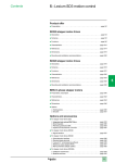
Contents
Application Source Code ...................................................................................................... 4
Typical Applications.............................................................................................................. 5
System................................................................................................................................... 6
Architecture ..................................................................................................................... 6
Installation ..................................................................................................................... 10
Hardware...............................................................................................................................................12
Software................................................................................................................................................21
Communication ......................................................................................................................................22
Implementation .............................................................................................................. 24
HMI .......................................................................................................................................................26
PLC.......................................................................................................................................................38
Devices .................................................................................................................................................53
Addendum........................................................................................................................... 67
Description of the example program............................................................................. 67
Detailed components list............................................................................................... 68
Component protection classes ..................................................................................... 71
Component Features ..................................................................................................... 72
Contact ................................................................................................................................ 75
Introduction
This document is intended to provide a quick introduction to the described System.
It is not intended to replace any specific product documentation. On the contrary, it offers
additional information to the product documentation, for installing, configuring and starting up the
system.
A detailed functional description or the specification for a specific user application is not part of
this document. Nevertheless, the document outlines some typical applications where the system
might be implemented.
Premium Lexium Altivar Sercos_EN.doc
Schneider Electric
2
Abbreviations
Word / Expression
AC
Advantys
Altivar (ATV)
CANopen
CB
CoDeSys
ConneXium
DC
EDS
E-OFF, E-STOP
Harmony
HMI
I/O
IclA (ICLA)
Lexium/Lexium05/LXM
Magelis
MB - SL
Micro
NIM
PC
Phaseo
PLC
Powersuite
Premium
Preventa
PS1131 (CoDeSys)
PS
SE
Sycon
Telefast
Tesys U
Twido
TwidoSoft
Unity (Pro)
Vijeo Designer
VSD
WxHxD
XBT-L1000
Premium Lexium Altivar Sercos_EN.doc
Signification
Alternating Current
SE product name for a family of I/O modules
SE product name for a family of VSDs
Name for a communications maschine bus system
Circuit Breaker
Hardware-independant IEC 61131-3 programming software
SE product name for a Family of Transparent Factory devices
Direct Current
Electronic Data Sheet
Emergency Off switch
SE product name for a family of switches and indicators
Human Machine Interface
Input/Output
SE product name for a compact drive
SE product name for a family of servo-drives
SE product name for a family of HMI-Devices
SE name for a serial Modbus communications protocol
SE product name for a middle range family of PLCs
SE product name for a Network Interface Module
Personal Computer
SE product name for a family of power supplies
Programmable Logic Computer
An SE software product for configuring ALTIVAR drives
SE product name for a middle range family of PLCs
SE product name for a family of safety devices
SE Product name for PLC programming software with CoDeSys
Power Supply
Schneider Electric
SE product name of a Field bus programming software
SE product name for a series of distributed I/O devices
SE product name for a decentralised I/O System
SE product name of a middle range family of PLCs
SE product name for a PLC programming software
SE product name for a PLC programming software
An SE software product for programming Magelis HMI devices
Variable Speed Drive
Dimensions : Width, Height and Depth
An SE software product for programming Magelis HMI devices
Schneider Electric
3
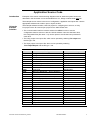
Application Source Code
Introduction
Examples of the source code and wiring diagrams used to attain the system function as
described in this document can be downloaded from our „Village“ website under this link.
The example source code is in the form of configuration, application and import files. Use the
appropriate software tool to either open or import the files.
Using the
Example
Software
The example software includes a UniLink project for configuring the Lexium17, a Unity
Pro project for the PLC and a Vijeo project for the HMI. Please note:
The communication interface must be switched to Offline in order to use the
configuration data for Lexium17 with the UniLink software. Once this has been done,
the configuration files (file name *.l17) can be opened. One file has been provided for
each drive.
The Unity project is an import file, which can be opened by selecting File->Open and
the file type *.xef.
The Vijeo project is an import file, which can be opened by selecting
File->Import/Export and the file type *.vdz.
Extension
AIW
CNF
CO
CSV
CTX
DCF
DIB
DOC
DOP
EDS
FEF
GSD
ISL
PB
PDF
PRO
PS2
RTF
STU
STX
TLX
TWD
VDZ
XEF
ZM2
Premium Lexium Altivar Sercos_EN.doc
File Type
Configuration File
Configuration File
CANopen definitions file
Comma Seperated Values, Spreadsheet
Device Configuration File
Device Independent Bitmap
Document file
Project File
Electronic Data Sheet – Device Definition
Export file
EDS file (Geraete Stamm Datei)
Island file, project file
Profibus definitions file
Portable Document Format - document
Project File
Export file
Rich Text File - document
Project file
Project file
Project file
Project file
Project file
Export file
Project File
Software Tool Required
Advantys
Sycon
Sycon
Twidosoft
Unity
Advantys
Sycon
Microsoft Word
Magelis XBTL
Industrial standard
PL7
Profibus
Advantys
Sycon
Adobe Acrobat
PS1131 - CoDeSys
Powersuite export file
Microsoft Word
Unity studio
PL7
Twinline control tool
TwidoSoft
Vijeo Designer
Unity Pro
Zeliosoft
Schneider Electric
4
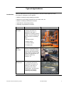
Typical Applications
Introduction
Here you will find a list of the typical applications, and their market segments, where
this system or subsystem can be applied:
Medium- and large-scale packaging machines
Machines for processing materials such as metal, wood, etc.
Medium- and large-scale textile machines
Applications in the printing industry
Assembly and production of devices
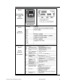
Application
Packaging
machines
Description
Image
Used for controlling various
packaging machines, for
example, in this case, a
palletizer for stacking goods on
a pallet. The drives need to be
able to perform the following
tasks:
Lift layers of jars
Position layers
Transport pallets
Transport jars
Textile
machines
Used for controlling transport
machines, folding and cutting
machines with several drives,
which need to be able to meet
a variety of requirements, for
example, positioning,
transport, etc.
Device
manufacture
Used for controlling machines
for assembling the various
components of a device, for
example, in this case, for
gluing skins into control
cabinet doors. The drives are
responsible for transport,
positioning and pumping.
Premium Lexium Altivar Sercos_EN.doc
Schneider Electric
5
System
Introduction
The system chapter describes the architecture, the dimensions, the quantities and different
types of components used within this system.
Architecture
General
The system comprises of a load component, a safety component and a control
component.
The load component is responsible for various requirements in respect of the drives,
with the result that a variety of types of variable speed controller (ATV31 and ATV71)
and servo drives are used. A single-phase or three-phase 400 V or 230 V AC power
supply is used; appropriate motor circuit breakers are provided. There is also a 24 V DC
power supply for the various control units (servos, safety, PLC, etc.).
The safety component comprises two Category 4 safety circuits for an emergency-off
shutdown and for monitoring doors. As well as door safety being an option, the drives
can be assigned to different safety circuits for the purpose of door monitoring.
The control system comprises a PLC with central acquisition of the various input and
output data. In the case of the variable speed drives, the drives are linked to the control
system via I/O signals, whereas the Sercos bus is used for the servo controllers. It also
features a graphic display terminal (XBGT HMI) that communicates with the PLC using
the Unitelway protocol and is used for plant control.
Premium Lexium Altivar Sercos_EN.doc
Schneider Electric
6
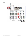
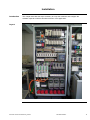
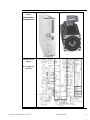
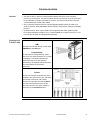
Layout
Premium Lexium Altivar Sercos_EN.doc
Schneider Electric
7
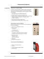
Components
Hardware:
Master switch (NSC100 Compact)
24 V power supply (Phaseo, 20 A)
ATV31 and ATV71 variable speed drives
Lexium17 drive controller incl. motors (servo)
Motor circuit breaker (GV2)
Category 4 safety modules (Preventa)
Emergency-off switch (XALK) and position switch (XCSA)
Contactors (LC1D)
Standard AC motor (7x)
Control system (PLC) incl. I/O cards (TSX Premium)
Graphic display terminal (Magelis XBTG)
Software:
Unity Pro 2.1 (PLC)
Vijeo Designer 4.2.0 (HMI)
UniLink 3.00 (Lexium17)
PowerSuite 2.0 (ATV31) (if applicable)
Quantities of
Components
The number of components needed to meet the requirements of the solution outlined
in this document will vary. A detailed list of the required components, including
quantities and part numbers, can be found in the Appendix to this document.
Degree of
Protection
Not all the components in this configuration are designed to withstand the same
environmental conditions. Some components may need additional protection, in the form of
housings, depending on the environment in which you intend to use them. For environmental
details of the individual components please refer to the list in the appendix of this document
and the appropriate user manual.
Premium Lexium Altivar Sercos_EN.doc
Schneider Electric
8
Technical
Data
Safety Notice
Supply voltage
400 V AC
Total supply output
~ 13 kW
Speed drive rated powers
4x 0.37 kW, 3x 0.75 kW, 4x ~1.6 kW
Motor brake
Not fitted
Connector cross-section
5x 2.5 mm² (L1, L2, L3, N, PE)
Safety category
Cat. 4 (emergency off and optional door monitoring)
The standard and level of safety you apply to your application is determined by your
system design and the overall extent to which your system may be a hazard to people and
machinery.
In this application example, Category 4 (according to EN 954-1) has been selected for the
purpose of ensuring safety. It is not possible to make a general statement in respect of the
safety or control category required for an application group. A detailed analysis of risks and
hazards must be carried out and as such requires the involvement of an actual machine.
Whether or not the above safety category should be applied to your system should be
ascertained with a proper risk analysis.
This document is not comprehensive for any systems using the given architecture and
does not absolve users of their duty to uphold the safety requirements with respect to the
equipment used in their systems or of compliance with either national or international
safety laws and regulations
Size/
Dimensions
The dimensions of the devices used, e.g., the PLC, variable speed drive and power
supply, support installation inside a control cabinet measuring 1200x1800x600 mm
(WxHxD).
Moreover, the graphic display terminal, the display elements used to indicate a
"group error", "emergency-off acknowledgment" and "door-safety acknowledgment"
can be built into the door of the control cabinet along with the emergency-off switch.
Premium Lexium Altivar Sercos_EN.doc
Schneider Electric
9
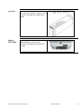
Installation
Introduction
This chapter describes the steps necessary to set up the hardware and configure the
software required to fulfil the described function of the application.
Layout
Premium Lexium Altivar Sercos_EN.doc
Schneider Electric
10
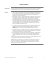
Notes
The programming of this application can be used as a basis for plant and machinery
needing a larger number of drives with a whole range of different requirements and
acquiring their input and output data locally via the PLC. The motors are controlled
independently by the PLC via I/O signals or, in the case of the servo drives, via the
Sercos bus.
The components listed in the next chapter represent a selection of the components
required. In particular, the number of motors used and their allocation to variable speed
drives and servos are determined by the relevant application (the number of inputs and
outputs may also vary).
Safety Category 4, which is suggested here as one possible option, is not necessarily
binding/not necessarily required for every application, as a risk analysis must be
produced and verified for each system (in accordance with national and/or international
standards and regulations).
Premium Lexium Altivar Sercos_EN.doc
Schneider Electric
11
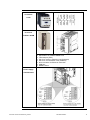
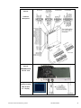
Hardware
General
The components designed for installation in a control cabinet, i.e., safety modules, line
circuit breakers, contactors, and motor circuit breakers, can be snapped onto a 35 mm
top-hat rail.
The master switch, Premium PLC, Phaseo power supply unit, and Altivar variable speed
drive are screwed directly onto the mounting plate. If you are using the Altivar 31, these
components can also be snapped onto a top-hat rail using an adapter.
The emergency-off and door-safety switches, as well as the housing for display and
acknowledge indicators, are designed for backplane assembly in the field; with the
exception of the door-safety switch, all switches can also be installed directly in a
control cabinet (e.g., in cabinet door) without their enclosing housings.
There are two options for installing XB5 pushbuttons or indicator lamps: These
pushbuttons or switches can be installed either in a 22 mm hole, e.g., drilled into the
front door of the control cabinet, or in an XALD-type housing suitable for up to
5 pushbuttons or indicator lamps. The XALD pushbutton housing is designed for
backplane assembly or direct wall mounting.
The individual components must be interconnected in accordance with the detailed
circuit diagram in order to ensure that they function correctly.
In addition to the wiring for the power circuits, the I/O signals are wired between the
PLC and the variable speed drives and a Sercos ring circuit installed between the PLC
and the servo controllers.
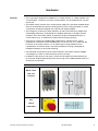
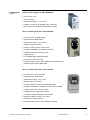
Mains switch
NSC 100
Compact
EMERGENCY
OFF
switch
XALK178G
Premium Lexium Altivar Sercos_EN.doc
Schneider Electric
12
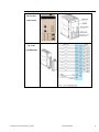
Selector and
Pushbutton
Switch
XB5
Safety Module
Category 4
XPSAF5130
Safety Switch
Door safety
XCSA703
Motor Circuit
Breaker
Motor Circuit
Breaker
(short-circuit
protection)
GV2-L
Premium Lexium Altivar Sercos_EN.doc
Schneider Electric
13
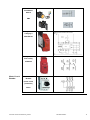
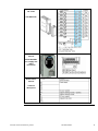
Motor
Contactors
LC1D
Premium PLC
Processor
TLX P57 3634M
1
2
3
5
6
8
9
10
Display LEDs
Eject button for PCMCIA-SRAM card
Terminal port (TER)
Slot for a memory expansion card (PCMCIA)
Slot for a communication card (PCMCIA)
RJ45 connector for Ethernet connection
USB port
RESET button
Premium PLC
Power Supply
TSX PSY 3610
Premium Lexium Altivar Sercos_EN.doc
Schneider Electric
14
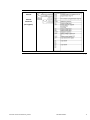
Premium PLC
Sercos Bus
TSX CSY 84
Premium PLC
I/O cards
TSX DEY16D2
Premium Lexium Altivar Sercos_EN.doc
Schneider Electric
15
Premium PLC
I/O cards
TSX DSY16T2
ATV31 Drive
Control
ATV31H037M2
incl. supply and
motor
connection
ATV31 Drive
Control
Terminal
description
Premium Lexium Altivar Sercos_EN.doc
Schneider Electric
16
ATV31 Drive
Control
Control
terminals
(I/O signals)
Continued on next page
Premium Lexium Altivar Sercos_EN.doc
Schneider Electric
17
ATV71 Drive
Control
ATV31H018M2
incl. supply and
motor
connection
ATV71 Drive
Control
Terminal
description
ATV71 Drive
Control
Control
terminals
(I/O signals)
Premium Lexium Altivar Sercos_EN.doc
Schneider Electric
18
Lexium 17 Drive
Control
MHDA1008N00
SER39B4L3SR
Lexium 17 Drive
Control
Circuit diagram,
functions
Continued on next page
Premium Lexium Altivar Sercos_EN.doc
Schneider Electric
19
Lexium 17 Drive
Control
Terminal
description
Lexium 17 Drive
Control
AM0SER001V00
Sercos card
Magelis Panel
Display Terminal
XBT-G 2330
5.7" display
Premium Lexium Altivar Sercos_EN.doc
Schneider Electric
20
Software
General
You will need to install the Unity Pro programming software for the Premium PLC and
the UniLink software for configuring the servo motors. You will also need the Vijeo
Designer software for configuring the HMI and creating the necessary diagrams. The
PowerSuite software can be installed in order to maximize user-friendliness in respect of
parameterization, archiving and simulation for the variable speed drive (ATV31).
However, this is currently only supported by ATV31 drives (and not ATV71).
The following installation requirements apply in respect of all software packages:
Operating system: Windows 2000 (SP1 minimum) or Windows XP
Free hard disk memory: At least 2.4 GB, 4.4 GB recommended
User memory: At least 512 MB, 1024 MB recommended
Processor: Pentium III or higher with min. 800 MHz, 1.2 GHz recommended
Interfaces: Serial interfaces as a minimum, USB recommended in addition
Additional software: Internet Explorer 5.5 or higher
Software
Premium Lexium Altivar Sercos_EN.doc
Schneider Electric
21
Communication
General
The Sercos bus is used for communication between the servo drive controllers
(Lexium17) and the PLC. For this purpose a Sercos ring must be set up from the PLC
to the individual controllers and back to the PLC. The servos and the PLC card are
connected directly via fiber optic cables.
The connection between the PLC and HMI (Magelis graphic panel) is made via a
serial connection cable (XBTZ968) and the devices communicate using the Unitelway
protocol.
An Ethernet port, which can be used to exchange data with other systems (other
PLCs, data acquisition systems, etc.), is also available as an option on the PLC. This
port can also be used as a programming interface.
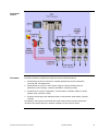
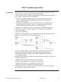
Premium PLC
TSX P57 3634
HMI
The HMI is connected directly via the cable
(XBTZ968) at the AUX port.
Programming
For the purpose of programming, cable
TSX PCX 1031 (switch position "0") is used
to establish a connection between the
serial interfaces on the PC and PLC.
Alternatively, an Ethernet link can be used,
once the Ethernet port has been
configured.
Sercos
The Sercos interface card TSX CSY 84 is
installed in two slots on the rack. The lower
slot number must be an odd number.
The Sercos ring starts from the TX Send
port and connects the servos in series.
After the last servo, the ring is closed by
connecting to the RX Receive port.
Premium Lexium Altivar Sercos_EN.doc
Schneider Electric
22
Lexium17
The Sercos plug-in card is installed in slot
X11 in the drive controller. The bus is wired
to the PLC using fiber optic cables (see
above).
Magelis
XBT-G2200
The connection to the PLC is made via the
cable (XBTZ968). A 25-pin sub D
connector is provided for this purpose on
the HMI.
Premium Lexium Altivar Sercos_EN.doc
Schneider Electric
23
Implementation
Introduction
The implementation chapter describes all the steps necessary to initialise, to configure, to
program and start-up the system to achieve the application functions as listed below.
Function
1. With the exception of the safety functions, the entire application is controlled via the
PLC. For this purpose, in the PLC, the input signals, the information from the drives
and the inputs are analyzed via the HMI and the drives are controlled and the
outputs set on the basis of these data.
2. Independently of the PLC, the application features two Category 4 safety circuits for
the emergency-off and door-safety functions. When tripped, these disconnect the
power supply to the drives and PLC outputs and inform the PLC accordingly.
3. The variable speed drives are controlled via I/O signals; to this end the signals for
forward and reverse travel are sent to the digital inputs on the variable speed drives.
The required speed is sent as an analog value. A fault signal and arrival at the
setpoint are signaled to the PLC via the outputs. The remaining free inputs on the
drives are available for extended functions.
4. In the case of the servo drives, travel information is exchanged via the Sercos bus.
This generally involves sending direct positioning data and the velocity to the
variable speed drives; special commands and parameters can also be sent,
however.
5. The application can run in automatic mode, which is controlled via a sequencer and
features one sequence for a variety of drive functions. Regardless of the sequencer,
two drives are also configured for continuous operation.
6. As well as displaying up-to-date information about the application, the HMI provides
access to application control functions. This usually involves switching between
manual and automatic mode. The drives can be controlled individually in manual
mode.
The PLC program, therefore, represents a framework for a typical application but without
simulating any of the actual functions of a specific machine.
Note: Both the ATV31 and the ATV71 can receive their control data from a choice of
two sources. For example, both device types can be set so that they are controlled
either via I/O signals or via a fieldbus (CANopen). Fieldbus mode usually requires a
state machine to be programmed, however.
Premium Lexium Altivar Sercos_EN.doc
Schneider Electric
24
Functional
Layout
Procedure
Proceed as follows to optimize the setup time of the individual products:
1. Parameterize the ATV31 and ATV71 variable speed drives (motor parameters,
control profile, I/O assignment).
2. Parameterize the Lexium17 servo drives using the UniLink software (Sercos
parameters, basic settings, controller optimization, operating modes).
3. Program the PLC (basic configuration, communication, variables, blocks for drives,
manual mode, automatic mode).
4. Configure and program the HMI (data areas, communication, data display, operator
controls).
Proceeding in the sequence described above will ensure that the relevant information
can either be imported directly or entered manually from the previous action.
Premium Lexium Altivar Sercos_EN.doc
Schneider Electric
25
HMI
Introduction
In this application, a Magelis XBT-G 2330 HMI connected to the PLC via the Unitelway
protocol is used. Vijeo Designer software is used to configure and program the terminal.
The steps to be taken in order to create and upload a program are described on the
following pages.
Proceed as follows to integrate the HMI:
1. Vijeo Designer function overview
2. Create new project (specify platform, hardware, communication).
3. Communication settings
4. Set up new variables
5. Set up animations
6. Check the project and download it
7. Overview of example project
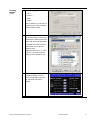
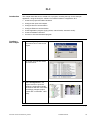
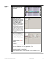
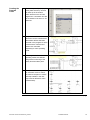
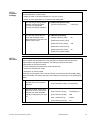
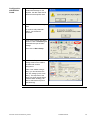
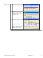
Function
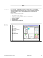
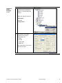
Overview
1
The Vijeo Designer environment
consists of the following
elements:
1 Navigator
2 Information display
3 Inspector
4 Data list
5 Feedback area
6 Toolbox
Premium Lexium Altivar Sercos_EN.doc
Schneider Electric
26
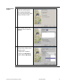
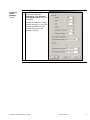
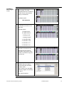
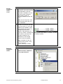
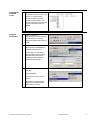
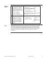
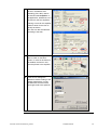
Create a New
Project
1
When Vijeo Designer starts up,
a selection window appears.
Select Create new Project.
You will be automatically guided
through subsequent steps.
2
Enter a project name for the
application and a comment (if
required).
3
Next select the target device
used and enter a logical name.
Example project:
Target name: “Platform1”
Target type: XBTG Series
XBT-G Model: XBT-G2330
Continued on next page
Premium Lexium Altivar Sercos_EN.doc
Schneider Electric
27
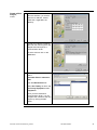
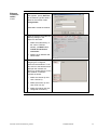
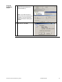
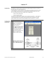
Create a New
Project,
4
In order to use the device's
Ethernet interface, you need to
enter the IP address, subnet
mask and, if applicable, the
gateway.
5
In order to be able to exchange
data with the control system, the
Magelis terminal requires a
communication driver.
Contd.
To select a driver click on the
Add button.
6
For communication with the PLC
select:
Schneider Electric Industries
SAS
from the Manufacturer list.
Select Uni-Telway as driver and
Uni-Telway Equipment under
Equipment.
Once you have selected a
communication driver, you can
complete the creation of the new
project by clicking the OK
button.
Premium Lexium Altivar Sercos_EN.doc
Schneider Electric
28
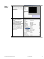
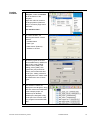
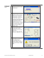
Communication
Settings
1
Once you have created the
project, VijeoDesigner displays
the workspace described above
with an empty edit screen on the
right-hand side.
2
To download the project you
must change the settings to
Ethernet.
To do this, right-click with the
mouse on the target in the
Navigator and select Download
in the Property Inspector.
In order that the project can be
transferred to the Magelis HMI,
you must select Ethernet as
well as the IP address and the
subnet mask.
Continued on next page
Premium Lexium Altivar Sercos_EN.doc
Schneider Electric
29
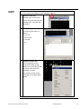
Communication
Settings,
Contd.
3
The interface parameters must
be declared to the Unitelway
driver for communication with
the PLC.
Right-click with the mouse on
Unitelway01
and select
Configuration….
4
The interface parameters
required for successful
configuration are:
COM1
RS-485
19,200 baud
8 data bits
The configuration must match
up to the PLC port.
Continued on next page
Premium Lexium Altivar Sercos_EN.doc
Schneider Electric
30
Communication
Settings
Contd.
5
Finally, call up the configuration
for the device set under
Unitelway01 in the Navigator
(UnitelwayDevice01) and check
the settings.
The default settings can usually
be used, although you may need
to modify the address if there
are several devices on the
Unitelway network.
Premium Lexium Altivar Sercos_EN.doc
Schneider Electric
31
Creating
Variables
1
To create new variables in the
Navigator, select the Variable
tab at the bottom of the
navigator.
Right-click with the mouse on
the target platform (Platform1
here) to access a popup menu
and select
New Variable->New….
2
To create variables, the
following information must be
entered:
Variable Name
Data Type
Data Source (External)
Address in the PLC
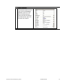
3
All memory types on the PLC
can be addressed (in addition to
flags (%M), words (%MW),
double words (%MD), and
floating points (%MF), also
system bits (%S) and words
(%SW), and constant bits and
words (%K, %KW)). All data to
be displayed on the Viewer must
be transferred to one of these
types.
4
The variables created are
displayed in the Navigator, along
with their names and addresses.
In the example project, all
variables (even Boolean
variables) are assigned to flag
words (the "Visu" section in the
PLC program is associated with
this).
Premium Lexium Altivar Sercos_EN.doc
Schneider Electric
32
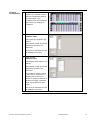
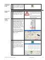
Creating
Images
The process for creating animations on screens will now be described using an example
text. The functions are similar for other animation elements.
1
Example: Enter text
Selection from the menu bar.
Various icons and elements are
available in the menu bar and
the toolbox.
2
Example: Edit text
The following information is
defined:
Font size
Text content
Font style
etc.
3
Example: Animate text
Start by selecting the text
element and calling up the
dialog box by right-clicking with
the mouse. Next select the
"Animation" function.
You can also do this via the
Properties screen (described
above).
Continued on next page
Premium Lexium Altivar Sercos_EN.doc
Schneider Electric
33
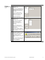
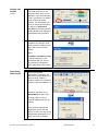
Creating
Images
4
Animation properties:
Color
Contd.
Position
Value
Visible
After activation you can select a
variable for the value animation
and the display format.
5
The variable to be animated can
be entered directly in the line or
looked up by selecting the (icon)
at the end of the line (light bulb).
A variable name that has been
entered but not recognized
appears in red.
Additional functions, e.g., value
inversion, can be executed by
clicking on the calculator icon.
6
The display opposite shows the
completed startup screen in
which the separate properties
for animation and actions
appear.
Continued on next page
Premium Lexium Altivar Sercos_EN.doc
Schneider Electric
34
7
Property Inspector
Each animation element on the
screen has its own Property
Inspector (right-click on the
object in the panel with the
mouse) with which all settings
associated with the object can
be viewed and modified.
Premium Lexium Altivar Sercos_EN.doc
Schneider Electric
35
Project
Download
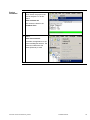
1
Before being downloaded to the
Touch Panel, the project must
first be analyzed. To do this,
select:
Build->Validate All
The results are listed in the
Feedback Zone.
2
Select:
Build->Download All
to transfer the application to the
connected Magelis terminal. The
connection selected at the
outset (Ethernet) is used.
Premium Lexium Altivar Sercos_EN.doc
Schneider Electric
36
Application
Overview
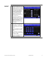
1
The example application features
a number of displays that can be
selected by the user. The display
opposite shows the main screen
from where all other displays can
be accessed. The application
overview, providing access to
error messages and safety
indicators, as well as to the
selection of the operating mode,
also appears here.
In principle, all screens are
structured in the same way and
all essential system status data
appear in the header. You can
switch from one screen to
another by clicking the buttons
in the footer.
2
All drives can run in manual
mode and be controlled directly
via the Viewer. To do this, you
must first switch to the relevant
screen.
There is one button for forward
travel and another for reverse
travel.
For the ATV71, you can also
specify a velocity and set ramps
by clicking on Set .
The status message and speed
display act as feedback.
Premium Lexium Altivar Sercos_EN.doc
Schneider Electric
37
PLC
Introduction
This chapter describes how to create a PLC program, including the logic for the example
application, using the Unity Pro software. Proceed as follows to integrate the PLC:
1. Create new project and select hardware.
2. Configure the inputs and outputs.
3. Configure Sercos communication.
4. Configure Ethernet communication.
5. Create application program (logic) (drives, manual mode, automatic mode).
6. Create visualization interface.
7. Connect to PLC and download program.
Creating a
New Project
1
After starting Unity, the first thing
you need to do is create a new
project.
2
To do this you must first select
the correct PLC.
3
Select Configuration in the
project browser to open the
hardware configuration. Modify
the number and size of the racks
accordingly (example project:
2 racks with 12 TSX RKY 12EX
slots).
Continued on next page
Premium Lexium Altivar Sercos_EN.doc
Schneider Electric
38
Creating a
New Project
4
Contd.
If you are using a double-width
power supply, you must
drag&drop the CPU to position 1
in order for the correct power
supply to be inserted.
(example project:
TSX PSU 3610).
5
Drag&drop is also used to move
the individual modules to the
right slots
example project:
112 digital inputs
64 digital outputs
8 analog inputs
8 analog outputs
7x TSX DEY16D2
4x TSX DSY 16T2
2x TSX AEY 414
2x TSX ASY 410.
6
The TSX CSY 84 card must be
selected for the Sercos bus.
Although the card must be
inserted in a slot with an even
number, it will also occupy the
previous slot.
7
Double-click on the CPU's upper
PCMCIA slot (A) to open a
window listing the permitted
PCMCIA cards.
Enter memory card TSX MRP
C001M (or higher if necessary)
for slot A.
Now save the project.
Premium Lexium Altivar Sercos_EN.doc
Schneider Electric
39
I/O Card
Configuration
1
Double-click on the relevant
module in the hardware view to
open the configuration area for
input and output cards.
Configure each card individually
and confirm your settings on
completion.
2
Digital inputs
(TSX DEY 16D2):
Eight inputs are grouped in one
channel.
Each channel (0 and 8) must be
assigned to the task to be
performed.
The inputs of channel 8 can also
be disabled (no function).
3
Digital outputs
(TSX DSY 16T2):
Eight outputs are grouped in one
channel.
Each channel (0 and 8) must be
assigned to the task to be
performed.
The behaviour of each channel
in the event of a fault and on
restarting also needs to be
defined. In respect of behavior in
the event of a fault, a separate
value can be defined for each
output.
The inputs of channel 8 can also
be disabled (no function).
Continued on next page
Premium Lexium Altivar Sercos_EN.doc
Schneider Electric
40
I/O Card
Configuration
4
Contd.
Analog inputs
(TSX AEY 414):
Each input is considered as an
individual channel, which must
be assigned to the task to be
performed.
The type of signal (current,
voltage, thermo) and a scale
also have to be entered.
The inputs can also be
smoothed using a filter function.
5
Analog outputs
(TSX AEY 414):
Each output is an individual
channel, which must be
assigned to the task to be
performed.
The type of signal (current,
voltage) and a scale also have
to be entered.
In respect of faults, a value to
which the relevant output is set
can be entered.
6
The configuration must then be
confirmed or validated. You can
do this by either closing the
configuration window or
selecting Validate from the Edit
menu.
Note: You can only save, close
and generate the project after
you have validated it.
Premium Lexium Altivar Sercos_EN.doc
Schneider Electric
41
Sercos
Communication
1
Double-click on the TSX CSY 84
card to open the Sercos bus
configuration.
2
The Sercos bus addresses
appear on the left of the
configuration screen as a tree.
Various functions are assigned
to the addresses. The bus
master (TSX CSY 84) has
address 0, the real axes used in
the application are assigned to
addresses 1 to 8.
The parameters associated with
the address selected in the tree
appear on the right. No settings
need to be made for the master,
although the optical power can
be modified.
3
Before you can parameterize an
axis, you must enable the
function on the left-hand side.
Now you can specify the limits
for position, velocity and
acceleration on the right-hand
side.
All settings marked in red are
obligatory.
The following data are used in
the project:
Limits: max. position: 5*105, min. position: -5*105, velocity: 1.2*104
Limits: max. acceleration 1.2*104, max. deceleration: 1.2*104
Units: metric linear (mm, mm/min, µm/s2)
Scale factor: numerator: 2, denominator: 1
Motion: destination window: 1.2*104, acceleration: 1.2*104, deceleration: 1.2*104
Continued on next page
Premium Lexium Altivar Sercos_EN.doc
Schneider Electric
42
Sercos
Communication
4
Contd.
The configuration must be
repeated for every axis requiring
parameterization, and then
confirmed or validated. You can
do this by either closing the
configuration window or
selecting Validate from the Edit
menu.
Note: You can only save, close
and build the project after you
have validated it.
5
In order to access the axis data,
you must create a T_CSY_IND
(IODDT)-type variable for each
configured axis and assign it to
the appropriate channel
address. Valid addresses are
%CHr.m.c where: r indicates the
rack number, m the slot and c
the Sercos address. The
addresses for the example
project are shown opposite.
With regard to the creation of variables, see also
"Creating Variables".
Note: A variable can also be
created for the master. In this
case it must be a
T_CSY_RING-type variable.
Ethernet
Communication
1
Select New Network… under
Communication->Networks
in the project browser.
Continued on next page
Premium Lexium Altivar Sercos_EN.doc
Schneider Electric
43
Ethernet
Communication
2
Contd.
In the Add Network dialog that
now appears, specify Ethernet
as the network type and enter a
name for the network under
Change Name.
Click OK to create the network.
3
Open the network and make the
following settings in the
sequence described:
1. Select the model family: In
the case of TSX P57
3634M, you MUST select
TCP/IP 10/100 Normal
connection.
2. Specify the IP address and
subnet mask.
4
The final step consists of
assigning the configured
network to the hardware. To do
this, switch to the hardware view
and open the network connection by double-clicking on the
CPU network connection.
Proceed as follows:
1. Select the channel (in this
case: channel 3).
2. Select the function (in this
case: ETH TCP IP).
3. Select the network link (the
configured connection)
Premium Lexium Altivar Sercos_EN.doc
Schneider Electric
44
Address
Overview
Various hardware addresses, as well as memory bits and memory words, are used in
the PLC example program. To facilitate orientation, an overview of the addresses used
appears below in list format.
Type
Address
Comment
Digital inputs
%Ir.m.x
Digital inputs are specified on a hardware basis:
r indicates the rack number, m the slot and x the
input number.
Example: Emergency-off feedback %I0.3.0.
Digital outputs
%Qr.m.x
Digital outputs are specified on a hardware basis:
r indicates the rack number, m the slot and x the
input number.
Example: Indicator lamp for manual mode
%Q0.5.1.
Analog inputs
%IWr.m.c
Analog inputs are specified on a hardware basis:
r indicates the rack number, m the slot and c the
channel number.
Example: ATV feedback %IW0.7.0
Analog outputs
%QWr.m.c
Analog outputs are specified on a hardware basis:
r indicates the rack number, m the slot and c the
channel number.
Example: ATV setpoint %QW0.8.0
Sercos axes
%CHr.m.c
Axis data via the Sercos bus are addressed on a
hardware basis: r indicates the rack number,
m the slot and c the Sercos address.
Example: Axis at Sercos address 8 %CH0.10.8
Sercos master
%CHr.m.c
Sercos-master data are addressed on a hardware
basis: r indicates the rack number, m the slot and
c the Sercos address.
Example: Master %CH0.10.0 (type:
T_CSY_RING)
Data for Viewer
%MW200
to
%MW299
Data for Viewer are written to flag words.
Individual bits are written via block
BIT_TO_WORD.
Example: Motor velocity %MW220
Data from Viewer
%MW300
to
%MW399
Data from Viewer are read by flag words.
Individual bits are extracted via block
WORD_TO_BIT.
Example: Motor velocity %MW220
Premium Lexium Altivar Sercos_EN.doc
Schneider Electric
45
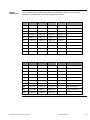
Altivar
Addressing
The I/O signals for the variable speed drives are addressed in the PLC to the following
addresses. The tables also show what the signals are used for.
PIN
1st ATV31
2nd ATV31
3rd ATV31
4th ATV31
LI1
%Q0.6.0
%Q0.6.4
%Q0.6.8
%Q0.6.12
Forward
LI2
%Q0.6.1
%Q0.6.5
%Q0.6.9
%Q0.6.13
Reverse
LI3
%Q0.6.2
%Q0.6.6
%Q0.6.10
%Q0.6.14
LI4
%Q0.6.3
%Q0.6.7
%Q0.6.11
%Q0.6.15
LI5
%Q1.7.0
%Q1.7.2
%Q1.7.4
%Q1.7.6
LI6
%Q1.7.1
%Q1.7.3
%Q1.7.5
%Q1.7.7
R1A
%I1.2.0
%I1.2.2
%I1.2.4
%I1.2.6
Fault
R2A
%I1.2.1
%I1.2.3
%I1.2.5
%I1.2.7
Speed reached
AI3
%QW0.8.0
%QW0.8.1
%QW0.8.2
%QW0.8.3
Speed set point
AOC
%IW0.7.0
%IW0.7.1
%IW0.7.2
%IW0.7.3
PIN
1st ATV71
2nd ATV71
3rd ATV71
LI1
%Q1.6.0
%Q1.6.4
%Q1.6.8
Forward
LI2
%Q1.6.1
%Q1.6.5
%Q1.6.9
Reverse
LI3
%Q1.6.2
%Q1.6.6
%Q1.6.10
Fast stop
LI4
%Q1.6.3
%Q1.6.7
%Q1.6.11
Ramp switchover
LI5
%Q1.7.8
%Q1.7.10
%Q1.7.12
LI6
%Q1.7.9
%Q1.7.11
%Q1.7.13
R1A
%I1.2.0
%I1.2.2
%I1.2.4
Fault
R2A
%I1.2.1
%I1.2.3
%I1.2.5
Speed reached
AI2
%QW1.9.0
%QW1.9.1
%QW1.9.2
Speed set point
AO1
%IW1.8.0
%IW1.8.1
%IW1.8.2
Premium Lexium Altivar Sercos_EN.doc
Use
Use
Source switchover
Schneider Electric
46
Creating the
Application
Program
The application program logically simulates the machine and its function. This document
and the example application are only able to outline the basic framework for a program
of this type. The key steps required to create the application program are outlined below:
1. Creation of variables and I/O assignment
2. Creation of the controls for the servo drives via the Sercos bus
3. Application program and logic creation (motor control, mode control, interfaces for
visualization)
Creating
Variables
1
Variables are declared and
assigned to inputs and outputs
in the Data Editor. The following
information is required for a
variable:
Name
Type
Address (if applicable)
Init value (if applicable)
Comment
Variables are created when they
are entered in the Data Editor
table.
2
In the example program, as well
as elementary variables for
digital and analog data,
structures are also used for data
exchange with the variable
speed drives.
These can be created on the
DDT Types tab in the Data
Editor. As well as the name and
comment, you need to declare
the individual elements of the
structure.
Right-click with the mouse and
select Analyze type to complete
the definition of the structure.
The types can then be used in
the context of variable declaration.
Premium Lexium Altivar Sercos_EN.doc
Schneider Electric
47
Controlling
the Servos
1
In order to control the servo
drives via the Sercos bus, you
must first initialize the bus and
set the enables.
In the example program this is
done using the "Sercos" DFB.
2
Once the enables have been
set, motion commands can be
transmitted to the servos using
the WRITE_CMD function.
The parameters differ according
to the motion command. The
example shows an absolute
positioning movement.
3
In the example project a
distinction is made between
automatic and manual mode for
the servos.
Automatic mode is controlled via
a sequencer, in whose action
sections motion commands are
set using WRITE_CMD.
For manual mode a DFB has
been written that can be used to
enable and move the servo and
return it to the home position.
Creating
DFBs
1
The definition of a DFB also
starts in the Data Editor (DFB
tab), where the inputs and
outputs, as well as the internal
variables of the DFB, have to be
defined.
The program sections of the
DFB can also be created here.
Continued on next page
Premium Lexium Altivar Sercos_EN.doc
Schneider Electric
48
2
The DFB is programmed as
structured text in one section in
the example program.
Programming is performed in
the editor, where code can be
entered.
Auxiliary functions for calling
individual blocks are also
available.
3
The blocks are called in the
section in which instantiation is
takes place (the simplest way to
call a block is to use the Ctrl+D
or Ctrl+I shortcut).
Once a block has been called,
its name must be entered. The
block can then be positioned.
Creating the
Program
1
In the example program, the
application logic has been
programmed as a function block
diagram (FBD).
Completed units form a section.
The section must be created
first. You do this in the project
browser, under Program, in the
associated task (right-click with
the mouse to open the relevant
menu).
2
Once you have created a new
section you will need to enter a
name and programming
language for it.
In the example programs, with
the exception of automatic
control, all sections are
programmed in FBD.
Premium Lexium Altivar Sercos_EN.doc
Schneider Electric
49
Creating the
Program
3
The blocks (Ctrl+D) or popup
menu (data selection) can then
be called up in the section.
Other elements such as links,
negations or comments can also
be accessed in this menu or via
shortcuts.
4
A separate section in which
directions can be controlled and
parameters defined has been
provided in the program for each
individual drive. Directions of
rotation are controlled
separately for each operating
mode.
5
In the "application" section, the
operating modes are defined
and general monitoring of the
safety functions takes place.
6
A sequencer has been provided
for automatic mode to control
the machine sequence. Actions
and step enables in the next
step must be defined for each
individual step.
Contd.
Continued on next page
Premium Lexium Altivar Sercos_EN.doc
Schneider Electric
50
Creating the
Program
7
Data are transferred between
the PLC and Viewer in the "visu"
section. It is here that the
necessary data are written
to/read from flag words. The
principle that logic functions can
only be executed in the PLC
applies.
1
Upon completion of
programming, the entire project
must be rebuilt. To do this,
select the relevant menu item or
button.
2
You must define the PLC
address before establishing a
connection with the PLC.
Contd.
Program
Download
In this case, the UniTelway
protocol (UNTLW01) must be
selected and the PLC SYS
(standard system address)
entered as the address.
3
The connection is established by
selecting
PLC->Connect
Or clicking on the icon in the
toolbar.
Remember: the appropriate
programming cable must be
connected to the PLC.
Premium Lexium Altivar Sercos_EN.doc
Schneider Electric
51
Program
Download
4
Contd.
The program can now transfer
data to the PLC and the PLC
can be started up.
Note: If you want the PLC to
start as soon as the download is
complete, you must check the
relevant box before starting the
transfer
5
Start the PLC with OK.
Premium Lexium Altivar Sercos_EN.doc
Schneider Electric
52
Devices
ATV31 variable speed drive
Introduction
The settings for the ATV31 variable speed drive can either be made manually using the
control buttons on the device or by means of the PowerSuite configuration software.
Subsequently, the configuration only is written via the control buttons, in order to retain
consistency between the parameter settings on the ATV31 and those on the ATV71.
In order for the ATV31 to be controlled via I/O signals, the following settings must be
made as a minimum:
Assignment of the control profile and use of the I/O signals
The line frequency and motor data in accordance with the rating plate
ATV31
Parameters
1
All parameters are set manually
using the control buttons on the
device.
2
Use the control buttons to select
the "Inputs/Outputs" ("I_O")
submenu. The I/O signals are
set here:
"tCC" 2- or 3-wire operation
"tct" Edges or signals
"rrS" Signal for reverse
2-wire operation with edges is
selected for the variable speed
drives in the application.
Reverse travel is assigned to
input LI2.
Note: Selecting 2-wire operation
automatically assigns forward
travel to input LI1.
3
The source for the speed setting
should be specified in the
Control (Ctl) menu:
"Fr1" Frequency setpoint
The analog current input (AI3) is
selected for all variable speed
drives in the application.
Premium Lexium Altivar Sercos_EN.doc
Schneider Electric
53
ATV31
Parameters
4
Contd.
Use the control buttons to select
the "Motor control" ("drC")
submenu. The motor
parameters are set here:
"bFr" Output frequency
"UnS" Rated motor voltage
"FrS" Rated motor frequency
"nCr" Rated motor current
"nSP" Rated motor speed
"Cos" Motor power factor
All motor data must be taken
from the rating plate.
5
For feedback from the variable
speed drive, data can also be
assigned to the two digital
outputs in the "Inputs/Outputs"
("I_O") menu. The variable
speed drive fault message is
assigned to the first output by
default.
"r1" Output 1
"r2" Output 2
In the application, arrival at the
setpoint is assigned to the
second output. The chart
opposite shows the possible
functions for the inputs and
outputs on the ATV31.
Note
The above parameters represent a minimum configuration in order to be able to run the
drive and the motor connected to it safely. Depending on the application, we also
recommend modifying regulation via the drive (V/f characteristic) to the application
(e.g., pumps or constant torque) by setting the "UFt" parameter accordingly in the
"Motor control" menu.
If necessary, other parameters such as those associated with the configuration of the
inputs, the setting of the ramps or the use of preset frequencies can also be modified in
the same way. If these parameters are also to be modified from the application, they
must be addressed accordingly via I/O signals.
Premium Lexium Altivar Sercos_EN.doc
Schneider Electric
54
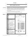
ATV71 variable speed drive
Introduction
The ATV71 drive can only be configured via the graphic display terminal on the device.
This must also be used for setting up operation via I/O signals.
The ATV71 has a number of different operating profiles, which mainly apply to operation
with a fieldbus. There are two basic configurations:
The ATV71 operates in the DSP402 profile, in other words the DriveCom state
machine is absolutely essential for fieldbus operation but is not necessary for
operation with I/O signals.
The ATV71 operates in the IO profile; individual functions, e.g., forward travel, are
declared explicitly to the ATV71 (via bus or I/O signal) and the setpoint velocity
(reference) is also transmitted via the bus or as an analog signal.
In both cases, it is possible to switch the control signals or setpoint velocity between
different sources (bus, I/O signals, display terminal). The following are available:
Two control registers
Three velocity references
Switchover can be independent in each configuration, although the DSP402 profile also
supports "not separate" switchover (not separate mode).
As shown in the figures above, appropriate sources such as terminals or bus can be
assigned to the channels for both the control register and the setpoint velocity.
Switchover parameters are available, which can be assigned with a switch signal,
e.g., a digital input signal.
Taking into account the control options, the following points are relevant in respect of the
configuration of the ATV71:
1. Setting of pulse or permanent signals (3- or 2-wire control)
2. Setting of motor parameters in accordance with rating plate
3. Selection of the profile and, if applicable, the switchover type
4. Selection of sources for channels and of switchover signals
In the application only the IO profile is used for the ATV71, since the DSP profile offers
no advantages for operation with I/O signals.
Premium Lexium Altivar Sercos_EN.doc
Schneider Electric
55
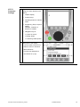
ATV71
Parameter
Settings
1
All parameters are set manually
using the control buttons on the
device.
1. Graphic display
2. Function keys
3. Start/Stop button for manual
mode
4. Escape key (Esc) to reject a
setting
Fwd/Rev: Inversion of
direction of rotation
5. Navigation key for:
Control in menus
Editing values
Confirming values (Enter)
2
Description of the display:
Current values of the ATV71
Name of menu or submenu
Menu elements
Function-key assignment
Scroll down or up (6)
Continued on next page
Premium Lexium Altivar Sercos_EN.doc
Schneider Electric
56
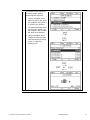
3
An example of how values are
set via the graphic display
terminal appears opposite.
1. Use the navigation key to
select the menu, then press
the navigation key ("Enter")
to confirm your selection.
2. The parameters associated
with the menu appear. Use
the navigation key to select
the value to be changed.
3. Use the navigation key to
change the value and then
save the value by pressing
"Enter" or reject it by
pressing "Esc".
Premium Lexium Altivar Sercos_EN.doc
Schneider Electric
57
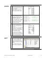
ATV71
Common
Settings
The settings common to all speed drives, regardless of the application profile selected,
are described here. These include:
Setting of pulse or permanent signals (3- or 2-wire control)
Setting of motor parameters in accordance with rating plate
1
2
The signal-type setting defines
whether permanent signals
(2-wire) or pulse signals
(3-wire) are used for operation.
[1.5 INPUTS/OUTPUTS CFG]
The data associated with the
motor and illustrated on the
rating plate have to be set in the
"Motor control" menu.
[1.4 MOTOR CONTROL]
[2/3 wire control (tCC)]:
2 wire (2C)
[Output frequency (bFr)]:
50
[Rated motor power (nPr)]:
[Rated motor volt. (UnS)]:
400
[Rated drive current (nCr)]:
[Rated motor freq. (FrS)]:
50
[Rated motor speed (nSP)]:
ATV71
IO Profile
The settings to be made for a speed drive using the IO profile with switchover of the
control register are described here. They represent an example that has also been
implemented in the application supplied. The following functions have been
implemented for the control system:
Profile setting with forward/reverse travel and fast stop
Switchover between two ramps
Switchover of control register
Unlike the control register, which can be switched over between the ATV display (HMI)
and the terminals, the velocity setpoint in this example is preset only via an analog input
signal.
1
2
The setting for the profile must
be made first; the IO profile is
selected.
[1.6 COMMAND]
The control-word, velocity and
switchover sources can now be
selected from those available.
Switchover takes place via input
LI6.
[1.6 COMMAND]
[Cmd channels (CHCF)]: Terminals (IO)
[Cmd channel 1 (Cd1)]:
Terminals (ter)
[Cmd channel 2 (Cd2)]:
HMI
[Ref.1 channel (Fr1)]:
AI2Ref
[Cmd switching (CCS)]:
LI6
Continued on next page
Premium Lexium Altivar Sercos_EN.doc
Schneider Electric
58
ATV71
IO Profile
3
Contd.
Now the individual ATV
functions must be assigned to
the individual bits in the switch
(type CDxx). The inputs (LIx)
and bits are linked automatically.
Bit 0 / LI1: Forward
Bit 1 / LI2: Reverse
Bit 2 / LI3: Fast stop
Bit 3 / LI4: Ramp switchover
4
Note
For feedback from the variable
speed drive, data can also be
assigned to the two digital
outputs in the "Inputs/Outputs"
("I_O") menu. The variable
speed drive fault message is
assigned to the first output by
default.
[1.5 INPUTS/OUTPUTS CFG]
[Reverse (rrS)]:
CD01
1.7 APPLICATION FUNCTIONS]
[Fast stop (FSt)]:
CD02
[Ramp switching (rPS)]:
CD03
Note: In the IO profile, forward is assigned to bit
0 automatically for two-wire control.
[1.5 INPUTS/OUTPUTS CFG]
[R1 assignment (r1]:
VSD fault (FLt)
[R2 assignment (r2]:
Frequency
setpoint reached
(SrA)
These parameters represent a minimum configuration in order to be able to run the drive
and the motor connected to it safely. Depending on the application, other parameters
such as those associated with the configuration of the inputs, the setting of the ramps or
the use of preset frequencies can also be modified in the same way. If these parameters
are also to be modified from the application, they must be written accordingly as
I/O signals.
Premium Lexium Altivar Sercos_EN.doc
Schneider Electric
59
Lexium 17
Introduction
The settings on Lexium 17D servo drives can be made using the buttons on the front of
the device and in the UniLink software tool.
In this application, by way of example, motion tasks are transmitted from the PLC to the
servo controllers via the Sercos bus to demonstrate the interplay between servo and
PLC. The following motion tasks are dealt with in the application:
Move to new position data
Move at a given velocity
The sequence outlined below is based on the controller being online, i.e., when there is
a connection between the controller and the software and the configuration is made
directly. Offline mode can also be used, although the text on buttons, etc., will vary.
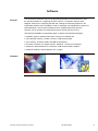
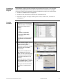
Configuration
with Unilink
1
When the software starts up, the
Communication dialog box
appears. You will see a list of
interfaces. Some will be
enabled, others not.
Select the appropriate interface,
e.g., COM1, to connect to the
Lexium drive. (The COM1 port
on the computer must be
connected to the X6 port on the
Lexium or to X6A on the
CANopen splitter interface.)
The figure opposite shows the
cable assignment or layout (part
number: AM0CAV001V003).
Continued on next page
Premium Lexium Altivar Sercos_EN.doc
Schneider Electric
60
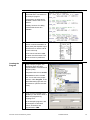
Configuration
with Unilink
2
Once communication has been
activated, the device will read
the parameters.
3
Once the parameters have been
uploaded, the basic screen will
appear with the relevant data. If
the device has not yet been
parameterized, a motor will not
yet have been configured.
Contd.
In order that even basic settings
can be made, the motor must
not be enabled. It can be
disabled by clicking on "Disable
(F12)" (circled in blue). You can
now continue to configure the
motor by clicking on "NN"
(marked in red).
4
The motor data are taken from
the rating plate. No other
information is required for all
drives listed.
Select the correct motor from
the list (e.g., SER39 B4 L3 SR).
5
It is not clear from the motor
type whether or not the drive
has a holding brake. A
corresponding prompt will,
therefore, appear. The example
motor does not have a holding
brake.
Continued on next page
Premium Lexium Altivar Sercos_EN.doc
Schneider Electric
61
Configuration
with Unilink
Contd.
6
As the changes made are
fundamental settings for the
amplifier, the data must first be
saved and the amplifier reset.
7
The connection is lost during the
reset.
To continue with parameterization, you will need to
reconnect.
8
Once communication has been
resumed, click on Disable again
to activate the input of basic
settings.
Then click on Basic Setup.
9
In the Basic Setup screen,
settings must/can be made in
the fields with a white
background.
Under "max. Mains Voltage"
(blue), you should select the
max. line voltage (in this case
400 V). The response of the
servo to a power supply failure
("Mains Phase missing") can
also be selected here (in this
case Warning).
Continued on next page
Premium Lexium Altivar Sercos_EN.doc
Schneider Electric
62
10 For Sercos communication with
the PLC, the address and
watchdog ("Ext. WD") need to
be entered under Amplifier. In
the application, addresses 5 to 8
are used for the four amplifiers.
Entering a name for the amplifier
makes it easier for the user to
identify the device.
The units can also be selected
according to the task.
11 The Sercos bus settings must
also be made on the basic
screen. In order for the button to
be enabled, the Sercos card
must be present in the amplifier.
12 In the Sercos settings the
address is fixed according to the
settings made above, so only
the baud rate and the overall
bus length need to be specified.
Continued on next page
Premium Lexium Altivar Sercos_EN.doc
Schneider Electric
63
Configuration
with Unilink
Contd.
13 These settings now need to be
saved in the amplifier by clicking
on the icon opposite. The device
does not, however, need to be
reset.
Startup with
Unilink
1
If the motor and amplifier have
been connected using power
and feedback cables, the drive
can be started up via Unilink.
Please be sure that the motors
are running off-load, in order not
to put personnel and machinery
at risk.
(For more information, see the
safety instructions in the servocomponent manuals.)
Startup with
Unilink,
2
continued
In order that the function can be
controlled via the software, the
external conditions must be set.
To do this, connect a 24 V
power supply to the "Enable"
hardware contact at terminal 15
(X3), which is associated with
the connection and enabling of
the power supply, and connect a
0 V supply to terminal 18.
You will also need to activate
the "SW-Enable" in the software.
The drive is supplied with power
and you will hear it switch to
position control.
3
Click Oscilloscope to open the
oscilloscope window, which
enables individual values to be
entered quickly and easily.
It is also possible to control the
drive via Unilink in this screen,
and this is what we are going to
do here.
Premium Lexium Altivar Sercos_EN.doc
Schneider Electric
64
Startup with
Unilink
4
Contd.
For speed mode, the best way
to test the function is to use
reversing mode, which can be
selected in the bottom left-hand
corner. The direction of rotation
will be inverted at specific
intervals. The parameters can
be set on a drive-specific basis
by clicking on Parameters.
Click Start to activate reversing
mode and Yes in the dialog box
that appears next to enable it.
5
Once the function test has been
completed, the settings made
can be saved by clicking on the
floppy disk icon in the main
screen.
Select
Parameters and Motion Tasks
in the next dialog box. We
recommend that you use the
drive names you assigned in
Basic Setup when saving data.
Duplicating
Other Drives
1
If the motor/amplifier
configuration is the same, the
data can be downloaded from a
file to the drive. Neither a
hardware enable nor a software
enable is required (Disable/F12).
If the drive has been set to
NO ENABLE (circled in red),
the floppy disk icon will no
longer be disabled and can be
invoked.
Once you have selected the
required file, an info box will
appear, in which you can specify
that particular parameters (e.g.,
name) are to be overwritten.
Premium Lexium Altivar Sercos_EN.doc
Schneider Electric
65
Duplicating
Other Drives
2
Once you have clicked on OK to
confirm this message, data will
begin to be downloaded to the
drive.
3
As the download brings about
significant changes, the data in
the amplifier must be saved and
a restart performed.
4
Following the restart, once the
connection with the device has
been re-established, the
characteristic data for the
Sercos bus and the device
name will need to be checked in
the Basic Setup screen.
Contd.
Note: The software enable must
be reset in order to do this.
Premium Lexium Altivar Sercos_EN.doc
Schneider Electric
66
Addendum
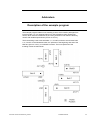
Description of the example program
The example program relates to two traveling cranes, which transfer packages from
incoming belts 1 to 3 to outgoing belts A to D. Each traveling crane requires two
servos, which execute movements in the x and y directions. The belts are driven by
motors with variable speed drives (ATV31 or ATV71).
The first traveling crane works with belts 1, 2, A and B, while the second uses belts
2, 3, C and D. In the illustration below, the positions of the beginning and end of the
belts are given as x and y co-ordinates in meters. The home positions of the
traveling cranes are also shown.
Premium Lexium Altivar Sercos_EN.doc
Schneider Electric
67
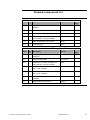
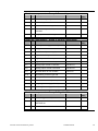
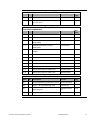
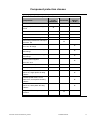
Detailed components list
Hardware components – Group 1: Master switch
Item
Qty
Description
Part no.
1.1
1
3-pin Compact master switch
NSC100
28122
1.2
1
3-pin terminal cover
28034
1.3
1
230 V undervoltage release
28082
1.4
1
Undervoltage release fuse and 230 V
load contactor 1 A (type C MCB)
25020
1.5
1
Alarm accessories 1 NC contact
29450
1.6
1
Locking device
29370
Rev./
Vers.
Hardware components – Group 2: Emergency off
Item
Qty
Description
Part no.
2.1
1
Emergency-off switch with overload
protection
XALK178-G
2.2
1
Preventa safety relay
XPSAF5130
2.3
1
Emergency-off safety fuse and 24 V
load contactor 3 A (type C MCB)
25022
2.4
2
Redundant load contactor 25 A
230 V control voltage
LC1D25P7
2.5
2
Redundant load contactor 12 A
230 V control voltage
LC1D25P7
2.6
1
ACK and safety indicator pushbutton
activated
XB5AW-36B5
2.7
1
Single-pushbutton housing
XALD01
Premium Lexium Altivar Sercos_EN.doc
Schneider Electric
Rev./
Vers.
68
Hardware components – Group 3: Door safety
Item
Qty
Description
Part no.
3.1
1
Preventa safety relay
XPSAF5130
3.2
2
Door-safety switch
XCSA701
3.3
1
Actuator for door-safety switch
XCSZ02
3.4
1
ACK and safety indicator pushbutton
activated
XB5AW-36B5
3.5
1
Single-pushbutton housing
XALD01
Rev./
Vers.
Hardware components – Group 4: Control components
Item
Qty
Description
Part no.
4.1
2
Primary fuse 3 A (type C MCB)
25022
4.2
1
Unity processor
TSX P57 3634M
4.3
2
24 V DC 36 W power supply
TSX PSY3610
4.4
2
Expandable backplane 12 slots
TSX RKY12EX
4.5
7
Digital input module 16 inputs
TSX DEY16D2
4.6
4
Digital output module 16 outputs
TSX DSY 16T2
4.7
2
Analog input module 4 channels
TSX AEY414
4.8
2
Analog output module 4 channels
TSX ASY410
4.9
15
Terminal block for I/O modules
TSX BLY01
4.10
1
Terminating resistors type A/B
TSX TLYEX
4.11
1
Backplane connection cable
TSX CBY010K
4.12
1
8-axis motion control (Sercos)
TSX CSY 84
4.13
4
Outgoing fuse 6 A (type Z MCB)
26139
4.14
4
Incoming fuse 1 A (type Z MCB)
26133
Rev./
Vers.
Hardware components – Group 5: Magelis HMI
Item
Qty
Description
Part no.
5.1
1
Fuse 1 A (type C MCB)
25020
5.2
1
Magelis panel XBT-G 2330, 5.7", color,
with Ethernet
XBTG2330
5.3
1
Interface cable to Premium PLC
XBTZ968
Premium Lexium Altivar Sercos_EN.doc
Schneider Electric
Rev./
Vers.
69
Hardware components – Group 6: 24 V power supplies
Item
Qty
Description
Part no.
6.1
1
Three-phase fuse, 2.5 ... 4 A
GV2ME08
6.2
1
400 V AC three-phase power supply,
24 V DC, 20 A
ABL7UEQ24200
Rev./
Vers.
Hardware components – Group 7: Variable speed drives, servos
and load components
Item
Qty
Description
Part no.
7.1
11
Motor circuit breaker 6.3 A
GV2L10
7.2
11
Auxiliary-switch attachment
GVAE11
7.3
4
Variable speed drive 0.37 kW
single-phase
ATV31H037M2
7.4
3
Variable speed drive 0.75 kW
three-phase
ATV31H075N4
7.5
18
Load contactor 9 A, 24 V control
voltage
LC1D09BD
7.6
4
Lexium17 drive controller
MHDA1008N00
7.7
4
Servo motor 0.6 kW
SER39A4L7SRAA
7.8
4
Power cable, 3 m
LXACPAAA031
7.9
4
Feedback cable, 3 m
LXACFACA031
7.10
4
Sercos plug-in card for Lexium17
AM0SER001V000
7.11
3
Sercos fiber optic bus cable 0.3 m
990 MCO 000 01
7.12
2
Sercos fiber optic bus cable 4.5 m
990 MCO 000 01
Rev./
Vers.
Software components – Group 8
Item
Qty
Description
Part no.
Rev./
Vers.
8.1
1
Unity programming software XL V2.0.2
UNYSPUEFUCD21
2.1
8.2
1
Unity <> PLC programming cable
TSXPCX1031
8.3
1
Magelis XBT-G programming software
Vijeo Designer
VJDSPULFUCDV1
0M
8.4
1
Magelis programming cable
XBTZG915
Premium Lexium Altivar Sercos_EN.doc
Schneider Electric
4.2.0
70
Component protection classes
Iinstallation locations/protection classes
Components
In the field,
on site
IP 55/IP 65
Front IP 65
Master switch NSC100
Emergency-off switch housing
XALK
X
X
Preventa modules XPSAF5130
Position switch XCSA
X
Single pushbutton housing XALD
X
Illuminated pushbuttons and lamps,
all colors, flat
Control
Cabinet
IP 20
X
X
Contactors, LC1, 230 V AC or
24 V DC, all ratings
X
Miniature circuit breakers, all types
and ratings
X
Motor protection switches, all types
and ratings
X
Phaseo power supplies
X
24 V DC, 20 A
Premium PLC components
X
CANopen taps with CAN cable
X
Variable speed drives, ATV31
230 V AC, single-phase all rating
classes
X
Variable speed drives, ATV71
4000 V AC, three-phase all rating
classes
X
Lexium17 drive controllers,
400 V AC, three-phase all rating
classes
X
Magelis XBTG touch panel, all
versions
Premium Lexium Altivar Sercos_EN.doc
X
Schneider Electric
71
Component Features
Components
Premium PLC: TSX P57 3634M
A Premium PLC power base (3 Series) is used in the example,
along with the associated modules for the inputs and outputs.
The performance characteristics for the PLC (TSX P57 3634M)
are as follows:
1024 digital I/O points, 128 analog I/O points
32 special modules (counter, axis control, etc.)
Program memory: 192 kB (with PCMCIA card up to 1792 kB)
3 fieldbuses (Interbus, Profibus), 1 CANopen, 8 ASi
encoders, 1 Ethernet
Serial interface and built-in Ethernet link
5 programming languages (FBD, LD, SFC, IL, ST)
Sercos master module: TSX CSY 84
Master interface module for Premium PLCs with the following
technical specifications:
Control of 2 or 4 MBaud Sercos ring
Control of axes
8 real axes
4 imaginary axes
Control of axis groups
4 groups for master/slave mode (2 to 8 axes)
4 groups for linear interpolation (2 to 8 axes)
Standard functions:
Electronic gears
Electronic cam disk
Diagnostics
Configuration via Unity Pro
Preventa safety relays: XPSAF5130
Category 4 to EN 954 Part 1
24 V DC
3 safety-oriented switching contacts
Slimline design
Continued on next page
Premium Lexium Altivar Sercos_EN.doc
Schneider Electric
72
Components
Phaseo power supply unit: ABL7UEQ24200
Contd.
400 V AC/24 V DC
20 A secondary
Temperature range: - 10 to +50°C
Parallel or series circuit possible (max. 2 devices)
Short-circuit-proof and protected against overload
Altivar variable speed drive: ATV31H037M2
0.37 kW, 230 V AC single-phase
Integrated class B EMC filter
Temperature range: -10 to +50°C
Velocity range 0 to 200 Hz
Velocity control with flow vector check
Operation via Modbus or CANopen possible
2 analog inputs plus 1 analog output
6 digital inputs
2 or 3 digital status outputs possible
Protection of drive and motor
Compact design, side-by-side installation also possible on a
DIN rail using bracket VW3A11852
Altivar variable speed drive: ATV71H075N4
0.75 kW, 400 V AC three-phase
Integrated class B EMC filter
Temperature range: -10 to +50°C
Speed range 0 to 1000 Hz
Graphic display for control and parameterization
Operation via Modbus, CANopen or other buses possible
2 analog inputs plus 1 analog output
6 digital inputs, 2 digital status outputs
1 shutdown output (emergency-off function)
Expansion cards for buses, I/O, control
Protection of drive and motor
Compact design, side-by-side installation possible
Continued on next page
Premium Lexium Altivar Sercos_EN.doc
Schneider Electric
73
Components
Lexium 17 drive controller:
Contd.
3.6 A, 400 V AC three-phase
0.75 A, 24 V DC auxiliary voltage
Output current 3 A (overload 6 A)
Temperature range 0 to 40°C
Built-in line filter with CE certification
Regulation: Current: 62.5 s; velocity/position: 250 s
Controller can be configured for all brushless servo motors
Configuration and programming software with built-in
oscilloscope function
2 digital inputs, 5 digital outputs; 2 analog inputs, 2 analog
outputs
Built-in serial and CANopen interface
Expansion cards for communication, e.g., Sercos, possible
Circuit breaker: GV2L10
6.3 A
Short-circuit protection
Magnetic activation 33.5 A
Lockable
Premium Lexium Altivar Sercos_EN.doc
Schneider Electric
74
Contact
Author
Schneider Electric GmbH
Customer & Market
System & Architecture
Architecture Definition Support
Schneider Electric GmbH
Steinheimer Strasse 117
D - 63500 Seligenstadt
Germany
Premium Lexium Altivar Sercos_EN.doc
Phone
E-mail
+49 6182 81 2555
[email protected]
As standards, specifications and formats
are changed from time to time, please seek
confirmation of the information contained
in this publication.
75