1
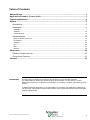
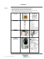
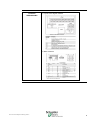
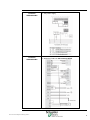
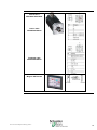
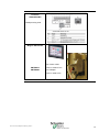
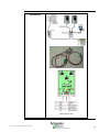
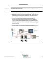
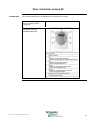
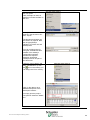
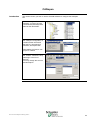
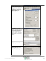
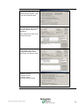
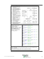
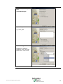
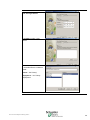
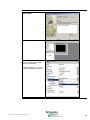
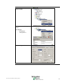
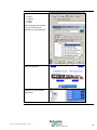
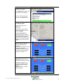
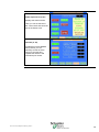
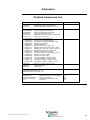
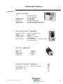
Micro and Lexium Magelis and Advantys System User Guide 33003456.03 [source code] Mar 2006 Table of Contents Abbreviations ........................................................................................................................ 3 Application Example - Source Code..................................................................................... 3 Typical Applications.............................................................................................................. 4 System................................................................................................................................... 5 Architecture ....................................................................................................................... 5 Installation ......................................................................................................................... 6 Hardware................................................................................................................................................ 7 Software................................................................................................................................................12 Communication ......................................................................................................................................13 Implementation ................................................................................................................ 18 Drive Controller Lexium 05......................................................................................................................19 I/O Platform ...........................................................................................................................................21 CANopen...............................................................................................................................................23 PLC.......................................................................................................................................................28 HMI .......................................................................................................................................................37 Devices .................................................................................................................................................49 Addendum........................................................................................................................... 50 Detailed Component List .................................................................................................. 50 Component Features ....................................................................................................... 51 Contact ................................................................................................................................ 53 Introduction This document is intended to provide a quick introduction to the described System. It is not intended to replace any specific product documentation. On the contrary, it offers additional information to the product documentation, for installing, configuring and starting up the system. A detailed functional description or the specification for a specific user application is not part of this document. Nevertheless, the document outlines some typical applications where the system might be implemented. Micro and Lexium Magelis and Advantys_EN.doc 2 Abbreviations Expression PLC HMI VVD PC AC DC PS I/O CB ESTOP Micro PL7 Phaseo Magelis Lexium/Lexium05 Advantys Signification Programmable Logic Computer Human Machine Interface Variable Velocity Drive Personal Computer Alternating current Direct current Power supply Input / Output Circuit Breaker Emergency Stop The product name of a Schneider Electric PLC The product name of a Schneider Electric PLC programming software The product name of a Schneider Electric power supply The product name of a Schneider Electric HMI Device The product name of a Schneider Electric VVD The product name of a Schneider Electric I/O-Platform Application Example - Source Code Introduction Examples of the source code used to attain the system function as described in this document can be downloaded from our „Village“ website under this link. Micro and Lexium Magelis and Advantys_EN.doc 3 Typical Applications Introduction Here you will find a list of the typical applications, and their market segments, where this system or subsystem can be applied: Application Description Packing machines for the packaging industry, used for labelling, packing, filling and paletting of goods. Specialised Machines For economical operation of special machines used in mounting, finishing, cutting etc. (e.g. food preparation, automatic assembly, woodworking) Conveyor System For use in sorting systems e.g. "pick and place". Micro and Lexium Magelis and Advantys_EN.doc Example 4 System Introduction This chapter describes the system architecture, components, size and quantity of those components used in the system. Architecture General The system consists of a PLC controlling two drive controllers each with a servomotor and a decentralised I/O platform. Control of the drives is via a full graphics touch screen. The field bus is CANopen, the control panel is connected via Modbus. For safety, a single mains switch is provided. Layout Components Hardware: TSX Micro (PLC) Phaseo (Power Supply) Lexium05 (VVD) Advantys STB (Remote I/O) Magelis XBTG (HMI) Servomotor Software: PL7 V4.4 (PLC) Advantys Configuration Software V1.20 (Remote I/O) Sycon V2.8 (CANopen) Vijeo-Designer V4.1.0 (HMI) PowerSuite V2.0 (Lexium05) Quantities For a stand alone application, only one of each component is required. Dimensions Due to the compact size of the components it is possible to contain the system in a single cabinet. The Magelis XBTN could be built into the front door of the cabinet Micro and Lexium Magelis and Advantys_EN.doc 5 Installation Introduction This chapter describes the steps necessary to set up the hardware and configure the software for the described application. Layout Function: PLC Program / HMI Usage The User can control two Lexium05 drive controllers using the fully graphic Magelis touch panel. The Lexium05 units occupy addresses 80 and 81 on the CANopen bus. After switching on, the Lexium05‘s can be put into „run“ modus using the „power up“ switch on the Magelis touch screen . There is an automatic mode and a manual mode. The key “AUTO” selects the automatic mode and starts a speed ramp. Manual mode provides access to the state machine of the two drive controllers. The user can manually start and stop the two controllers. The speed and direction of the two controllers can be adjusted. Micro and Lexium Magelis and Advantys_EN.doc 6 Hardware General The power supply and the Advantys need a DIN rail for mounting. Other devices can be mounted on the surface of the cabinet. 230VAC wiring between main switch, power supply and VVD. 24VDC wiring between power supply, PLC, HMI and control circuit of the VVD. Wiring of power and feedback cable between motor and VVD. Mains Switch VCF-02GE Power Supply ABL7RE2403 PLC Micro TSX3722101 Drive Controller Lexium05 LXM05AD10M2 Micro and Lexium Magelis and Advantys_EN.doc Mains- and Motor connection 7 Drive Controller Lexium05 LXM05AD10M2 Layout of the Signal contacts Motor contacts Micro and Lexium Magelis and Advantys_EN.doc 8 Drive Controller Lexium05 LXM05AD10M2 24V-power supply Drive Controller Lexium05 LXM05AD10M2 Wiring the Field bus, NO protected STOP Micro and Lexium Magelis and Advantys_EN.doc 9 AC - SynchronousServomotors SER3683L5SSOAOO Power cable GEA2M0AAAA003 Feedback cable GEA2EAAAAA003 HMI Magelis XBT-G2330 Micro and Lexium Magelis and Advantys_EN.doc 10 Advantys STB Advantys STB Power Supply Micro and Lexium Magelis and Advantys_EN.doc 11 Software General The Software for the Micro PLC, the full graphics Magelis touch screen and the configuration software for the CANopen bus must all be installed. The Front of the drive controller has a simple display and keypad for simple configuration. For more comfortable configuration, archiving and simulation possibilities, install the PowerSuite software. To do this you need a PC with a Microsoft Windows 2000 or Windows XP operating system. To start the software installation simply put the appropriate CDs in the CD drive of your PC – the installation starts automatically if you have set the “autostart” in Windows. If you have problems, check the product description of the particular software package. Micro and Lexium Magelis and Advantys_EN.doc 12 Communication General CANopen is used for the field bus communication between the Micro PLC, the Lexium05 drive controllers and the decentralised Advantys I/O platform. The full graphics Magelis touch screen is connected to the Micro PLC with a Modbus protocol. Modbus cabel between PLC and HMI CANopen cabel between PLC, VVD and Advantys by using a CANopen adapter. PLC Micro TSX3722101 Connecting the serial interface on the PC with PL7 and the Micro PLC using connecting cable TSX PCX 1031 To connect the Micro to the CANopen cable you need: TSX CPP 110 card in the PCMCIA Slot of the PLC (1) The TAP is fixed to a railing (2) Micro and Lexium Magelis and Advantys_EN.doc 13 Drive Controller Lexium05 LXM05AD10M2 CANopen using CN4 HMI Magelis XBT-G2330 DC- Power cable XBTZG915 XBTZG999 Comm. Cable to PLC incl. Adapter Comm. cable to PC Micro and Lexium Magelis and Advantys_EN.doc 14 Advantys STB CANopen Connection Advantys STB Programming Cable STB XCA 4002 Micro and Lexium Magelis and Advantys_EN.doc 15 CANopen Adapter VW3CANTAP2 Switch set to OFF Micro and Lexium Magelis and Advantys_EN.doc 16 CANopen – Plug 103643 (incl. end-resistor for connection to TSXCPP110 Tap and Advantys) CANopen – Cable DCA 701 (44170014 from Selectron) or UNITRONIC BUS CAN 2170261 (from LAPP) Micro and Lexium Magelis and Advantys_EN.doc 17 Implementation Introduction The implementation chapter describes all steps necessary to initialize, parameterize, program and to start-up the system. Function 1. After switching on the mains, the Lexium05 drive controllers can be put into “run” mode by pressing the “Power Up” key, for 2 seconds, on the Magelis screen. 2. After “Power Up” the PLC is in manual mode. In this mode, the user has access to the state machine of the two drive controllers. The drive controllers can be manually stopped and started. The speed and direction of the drive controllers can be adjusted. 3. The drive controllers must first be stopped to switch to automatic mode. Automatic mode can be selected on the magelis touch screen with the key “AUTO”. This starts a speed regulation program, raising the speed from zero to 600rpm in 1 minute. The speed remains constant for 10 minutes and then is reduced to –600 rpm over a period of 2 minutes. After another 10 second period the speed is reduced to zero over a 1 minute period. After a 10 second wait, the program is re-started. 4. In the case of errors, an error number is displayed on the Magelis touch screen. The user can refer to the user manual for an explanation of the error. Micro and Lexium Magelis and Advantys_EN.doc 18 Drive Controller Lexium 05 Introduction This section describes how to initialise the Lexium05 drive controller. After finishing the wiring the drive controller must be configured The parameters may be configured using the integrated HMI panel. Micro and Lexium Magelis and Advantys_EN.doc 19 All drive functions are blocked on first time power supply or on reloading of the factory setup using the Parameter PARfactorySet. A „First-Setup” must done. In this example the Addresses 80 and 81 are used and 500 KBaud is given as communication speed. After first setup the drive controller should be shown in the status display as „RDY“ (ready). Micro and Lexium Magelis and Advantys_EN.doc 20 I/O Platform Introduction This section describes the configuration of the Advantys I/O platform using the Advantys configurations software . After starting up the Advantys configuration software, a new workspace must be created. You must provide a path, a Wordspace-Name and an Island-Name. Then Choose the network interface for CANopen STB NCO 2212 Now add the other modules: STB PDT 3100 STB DRC 3210 STB DDI3610 STB ACO 1210 STB ACI 1230 Not forgetting the bus terminal. STB XMP 1100 The screen should now show: Micro and Lexium Magelis and Advantys_EN.doc 21 Via the Menu bar you can set the bus speed. Here, 500 kbps is used, as with the Lexium05 and later in the PLC. Next, you must create the EDS file. Use the menu “file” then “export”. The filename and folder can be chosen as required. Note the file type (EDS) is obligatory for future use and development. You can configure the I/O using the SYCON EDS files instead of the Advantys configuration software, however this requires extensive knowledge CANopen and is not part of this document Using the menu “Island” and then “I/O Definition” (or use the icon in the toolbar) you can assign the I/O to memory. Click on the data to get a detailed description in the description window… Or simply print the project. The printout shows the details too. Micro and Lexium Magelis and Advantys_EN.doc 22 CANopen Introduction This section shows you how to use the SYCON software to configure the CANopen bus Before starting the SYCON software, you must copy the Lexium05 and Advantys EDS files into the EDS folder. SYCON is used to describe the CANopen configuration. It contains all the information that the PLC programming software, will require later. After starting SYCON, a new project is created Use the menu “insert” and add the “master” TSX CPP 110 by selecting it in the list of devices. You may change the account and description. Micro and Lexium Magelis and Advantys_EN.doc 23 Insert a Node using the menu bar selections. After inputting the address and description, select the manufacturer and click on “add” to add it to the chosen devices Here the addresses 80 and 81 are used. See configuring the Lexium05. Now do the same for the second Lexium. The next node is the Advantys (Address 18). You should now have a screen showing: Micro and Lexium Magelis and Advantys_EN.doc 24 Next, set the baud rate. For this, select the master Using the menu “Setup”, then “Busparameter”. When the busparameter dialog opens, select 500kBits/s as communication speed and click on “OK”. A doubleclick on the first Lexium node opens the dialog for the node configuration. A list of the PDOs is displayed. For our application the 3rd. PDO is required. This PDO is the parameter for the speed control. First , set the device type to “Frequency Converter”. After a double click on “3rd receive PDO comm..” the following dialog appears. Click “OK” to accept the setup. Micro and Lexium Magelis and Advantys_EN.doc 25 After a doublclick on “3rd transmit PDO comm..” the following dialog appears, click “OK” and accept the setup. The Parameter setup for the first Lexium05 is now complete and the following window is displayed. Now repeat these steps for the second Lexium05. A doubleclick on the Advantys node displays the node configuration dialog. Select each PDO, one after the other. PDOs: “RxPDO1 Comm...” “RxPDO2 Comm...” “TxPDO1 Comm...” have the setup as shown: Micro and Lexium Magelis and Advantys_EN.doc 26 And PDO “TxPDO2 Com...” has the following setup: The Parameter setup for Advantys is now complete And the following dialog is displayed: Now save the project as xxx.co. Now you are ready to start on the PLC program. Micro and Lexium Magelis and Advantys_EN.doc 27 PLC Introduction The PLC section describes the steps necessary to create the PLC logic. For this we use the PL7 software. Start PL7 and create a new project. Make sure you select the correct PLC. Increase the number of words in the configurator. Configure the I/O modules. Doubleclick to choose the modules required. Micro and Lexium Magelis and Advantys_EN.doc 28 In “Hardware Configuration” click on the PCMCIA-Slot “COMM” . The configuration dialog for the communication appears. Select “Channel 1” . As Type select the CANopencard TSX CPP 100-110. In the same dialog you can setup the bus start up behaviour, I/O behaviour and the task in which the bus runs – select MAST. Using the Button “Select Database” select the configuration file you created with SYCON (xxx.co). Micro and Lexium Magelis and Advantys_EN.doc 29 CANopen requires 11 Input Words and 9 Output Words. Reserve 50 input and 50 output words. The inputs start at %MW600 The outputs start at %MW700 (These can be setup at another memory location). Clicking on “Bus configuration” opens a dialog with the bus details. Here the details for the first Lexium05. The addresses and symbol names are shown on the right. Here the details for the second Lexium05. Here the details for the Advantys. The data transfer with the Advantys is not handled in this application. As example, in the section “Auto_island” an on/off pulse is written to the output relay. Micro and Lexium Magelis and Advantys_EN.doc 30 For easier handling the I/Os are copied to a working register. Note: this is not mandatory. The sections “Bus_startup” and “System_bits” define the behavour on start up of the PLC. The section “Init” sets the nominal values for the rpm to 0 and 600. The interaction between the operating modes and changing of mode are defined in the state machine of the Lexium05 (equivalent to CANopen DSP402). The operating modes are changed using the controlword, the actual status is shown in the statusword. Micro and Lexium Magelis and Advantys_EN.doc 31 For the Lexium05 the operating modes are shown in rectangles numbered 1 to 9, changes of mode in circles numbered 0 to 16. Description of the operating modi. Conditions of standard operating modes are indicated with Bits 0 to 3, 5 and 6 in the statusword. The Statusword is read via the CANopen Bus and evaluated in the PLC section „Operation_mode“. The operating mode is written in %MW200 (%MW201for the second Lexium05). Micro and Lexium Magelis and Advantys_EN.doc 32 Change of operating mode is caused by either reacting to a direct command or control signal. A command is passed using the controlword. The mode changes 0, 1 and 14 are automated and cannot be influenced with a command. Mode changes using command are listed in the table here: The operating modi are set in the controlword Bits 0 to 3 and Bit 7 are used for a change of modus. The bit value „X“ indicates this field has no influence for the given mode change. After switching on, the Lexium05 should automatically be in mode 4 (rdy) i.e. “Ready to switch on” This is indicated on the status display of the Lexium05. Micro and Lexium Magelis and Advantys_EN.doc 33 To put the drive controller into operating mode 6 (run) “Operation enable” press the “Power Up” button on the Magelis touch screen. This activates the PLC Sections “Powerup_drive1” “Powerup_drive2” . In this Application the speed mode is used (see PDO 3). As the Lexium05 is in the wrong operating modus on re-start, the speed mode must be activated. To do this the Lexium05 need modus 6 (Operation enabled). Micro and Lexium Magelis and Advantys_EN.doc 34 Next, using the function WRITE_VAR a “03” (=speed mode) is written in the operations modi Register 6060:0hex of the Lexium. CANopen uses the datatype SDO for this. The CANopen Address of the Lexium05 is written in the Slave Address. For the first Lexium this is 80, for the second 81. The “03” (=speed mode) is written in %MW152 and the amount of data to be transferred (here, 1) is written in %MW507 (%MW504+3) . The same is also done for the second Lexium using the defined addresses for it. Micro and Lexium Magelis and Advantys_EN.doc 35 The error registers 603F:0hex in the Lexiums are cyclically read using the function Funktion READ_VAR. If the mode “AUTO” is selected on the Magelis touch screen, the PLC starts a speed ramp, passing the nominal value to the Lexium. The motor turns. Alternatively you can start the drive in manual mode. Here, any inputs on the Magelis are passed directly on to the Lexium. Micro and Lexium Magelis and Advantys_EN.doc 36 HMI Einführung This section describes the steps needed to create the Magelis images. For this we use Vijeo Designer. The Setup of the HMI is done as follows: Create a new project Give the project a name Specify the hardware Select new driver New screen Setup download Configure the Modbus connection Configure driver / Configure device Create new variables Create new screen Example of a numerical display Characteristics dialog Animation setup Check projekt Download Projekt The Vijeo Designer has the following components: 1 – Navigator 2 - Info-Display 3 – Inspector 4 – Data list 5 – Feedback Zone 6 – Toolbox Micro and Lexium Magelis and Advantys_EN.doc 37 After Starting Vijeo Designer, select Create New Project Input a Project Name e.g. Servo_HMI Select the target device Targetname: “Platform1” Targettype: “XBT –G Series XBTG Model: “XBT-G2330” Micro and Lexium Magelis and Advantys_EN.doc 38 Input the ethernet addresses for the target device. Use Add to select a new driver Manufacturer: “Schneider Electric Industries SAS” Driver: “Uni-Telway” Equipment: “ Uni-Telway Equipment” Micro and Lexium Magelis and Advantys_EN.doc 39 The new driver has now been added Neu Project Window Select the Download setup For the connection between the PC and Magelis. As an alternative, you could select the ethernet connection. Micro and Lexium Magelis and Advantys_EN.doc 40 Rename the communications device to PLC Configure the Uni-Telway driver I/O Manager – UniTelway01 – „Configuration..” Drive Configuration Micro and Lexium Magelis and Advantys_EN.doc 41 Equipment Configuration of the communications device Create a New Variable Micro and Lexium Magelis and Advantys_EN.doc 42 Setup the Variable Properties: Variable Name DataType Data Source – External – PLC Device Address in the PLC Create a New Panel Micro and Lexium Magelis and Advantys_EN.doc 43 Empty panel Example: Insert Text Select the tool in the tool bar The toolbar with the different tool icons is above the panel. Example: altering text Define the font size, font type, font style…. and type in the text. Micro and Lexium Magelis and Advantys_EN.doc 44 Property Inspector : Text attributes such as postion, size, colour can be changed here. Click on the text element in the panel window. Now with a right mouse click and select the menu Animation.. , you can animate the object. You can do this in the property inspector too. Micro and Lexium Magelis and Advantys_EN.doc 45 Animation Attributes: Colour Position Value Visible After activating the animation, you can select how the animation is to be displayed. Some examples of texts, text fields and graphics. The final screen with all the attributes for the animation and events. Micro and Lexium Magelis and Advantys_EN.doc 46 With Validate All you can analyse your project. The feedback zone gives you the results of the analysis. You can obtain the project analysis using Build All too. Downloading the project to the Magelis (HMI) Select the project in the Navigator. Using either a right mouse click on the project name or the menu Build , Select Download All to transfer the project to HMI. The transfer is done using the selected method (serial or ethernet). The Vijeo Designer package comes with a serial cable The screen Drive control is the start screen. Use the buttons to display other screeens. In the case of a power cut and restart the Lexium05 is indicated in status „4“ (ready to switch on) and operating mode „FC“ (Mode = -4). For the power up to work, the Power Up button must be pressed for at least 2 seconds. The status changes to "6" (Operation enable) and the operating mode to Speed (Mode = 3). Selecting "Auto" invokes a speed program. Micro and Lexium Magelis and Advantys_EN.doc 47 The screen Power up Drive 80 (or 81) displays the state machine. Here you can set the bits of the control word and check the bits in the status word. On the screen Drive 80 (or 81), provided the button manual was pressed, you can manually control the drive using run and stop and regulate the direction and revolutions per minute. Micro and Lexium Magelis and Advantys_EN.doc 48 Devices Introduction The Devices section describes the different steps needed to initialise and parameterise the device logic/behaviour to attain the specified system functionality. General Not available Micro and Lexium Magelis and Advantys_EN.doc 49 Addendum Detailed Component List Type / Software ABL7RE2403 VCF02GE XALK174G POWER SUPPLY 240VAC 1PH 24VDC 3A EMERGENCY ON/OFF MAINS SWITCH HOUSING BEST.M.PILZ SWITCH RT,1S 2Ö TSX3722101 TSXDMZ64DTK TSXDEZ32D2 TSXDSZ32T2 TSXPCX1031 TSXCPP110 MODICON TSX MICRO:TSX37-22, DIGITAL I/O-MODULE 32In/32Out DIG.INPUT MODULE,32In(24V)SCHR DIG. OUTPUT MODULE 32Out COMMUNICATION CABLE MULTIFUNCTIONAL CANopen PC-Card Type III Power Supply. 24VDC PDM STD. BUS connector CANOPEN NIM STD. Configuration Cable RS232 SUBD/HE13 2M SOCKETI/O TYP3 27MM SOCKET PDM 18MM MODULE 2A RELAIS C 24VDC / 2A MODULE E2KAN. 12BIT ISOLATED 0...20MA MODULE 6E 24VDC SINK 2 WIRE 0.1MS FIX. S BUS TERMINAL MODULE ISLAND BUS MODULE 2CHAN. 12BIT 0...20MA PLUG I/O 6 CONNECT. FEDERZUGKL. (20ST) SOCKET I/O TYPE1 13.5MM SOCKET I/O TYPE2 18MM PLUG I/O 6CONNECT. SCREW. (20ST) PLUG I/O 5CONNECT. SCREW. (20ST) PLUG NIM 2CONNECT. SCREW. (10ST) PLUG PDM 2 CONNECT. SCREW. (10 ST) STBPDT3100 STBNCO2212 STBXCA4002 STBXBA3000 STBXBA2200 STBDRC3210 STBACI1230 STBDDI3610 STBXMP1100 STBACO1210 STBXTS2100 STBXBA1000 STBXBA2000 STBXTS1100 STBXTS1110 STBXTS1120 STBXTS1130 XBTG2330 XBTZG915 XBTZG999 Revision/Version Colour TFT LCD 256 Colours 5,7 Inch Programming Cable Cable adapter LXM05AD10M2 Lexium05 230V/1F 750W GEA2M0AAAA003 Motor cable – 3m GEA2EAAAAA003 Geber cable – 3m TLXCDPL7PP44M STBSPU1000 VJDSPULFUCDV10M SYCSPULFUCD28M ??? Micro and Lexium Magelis and Advantys_EN.doc Software PL7 Pro V4.4 M Software ADVANTYS Incl. Cable RS232 Software Vijeo Designer Field bus Configurator SyCon V2.8 PowerSuite V4.4 V1.2 V4.1 V2.8 V2.0 50 Component Features Components PLC Micro TSX3722101 I/O : Program Memory : Data Memoryr : Networks : Expert modules : Programming : max. 256 digital I/Os max. 32 analog I/Os up to 128 KBytes up to 35 KBytes CANopen (via PCMCIA) Counters, Emergency off (not used) PL7-Micro (4 Languages IEC1131-3) Motor Control Lexium05 Performance output Voltage Fieldbus Interface Signal Interface RS 422-Interface Servo motor LXM05AD10M2 from 0,75 kW (Model Size 1) 230 V ~, 1-phasig CANopen 2 analog +/- 10 V Inputs and 8 digital I/Os for Pulse-/Direction – or A/B-Signal inputs or Encoder simulation SER3683L5S Performance RPM Nominal torque Torsion max. Voltage max. Phaseo Power Supply Unit 0,6 kW 12000 min-1 0,48 Nm 3,0 Nm 230 V ~ ABL7RE2403 Input Voltage 100…240 V ~, single phase, 50/60 Hz Ouput Voltage 24 V = Output power 3,0 A Micro and Lexium Magelis and Advantys_EN.doc 51 Components Contd. Magelis full graphics Touch Panel Display type Display Dimensions Protocol Connections Voltage XBTG2330 LCD-TFT 256 Colours 5,7" (320x240) Unitelway , Modbus, Modbus TCP/IP RS232C/RS485 , Ethernet 10BaseT 24 V = external PL7 MICRO Programming software TLXCDPL7PP44M Programming with Instruction List, Contact Plan and Structured Text Access to all application elements using the navigator Simplified hard- and software-configuration using special editors Two types of application: Mono-task or Multi-task Structuring of the Master- and Fast-task in sections Selection of a different programming language in each section Simple testing using automatically assembled animation tables Vijeo Designer VJDSPULFUCDV10M The user friendly configurations software, Vijeo Designer, allows for simple and fast development of projekts using configuration windows. Vijeo Designer allows the processing of process data using the touch panel XBT G and Java-Script. Some of the features: Navigator, Library of animated graphical objects, Online-Help, Error Report Display, Object Attributes Display, Variablelists. Micro and Lexium Magelis and Advantys_EN.doc 52 Contact Author Telephone E-Mail Schneider Electric GmbH Customer & Market System & Architecture Architecture Definition Support +49 6182 81 2555 [email protected] Schneider Electric GmbH Steinheimer Strasse 117 D - 63500 Seligenstadt Germany Micro and Lexium Magelis and Advantys_EN.doc As standards, specifications and designs change from time to time, please ask for confirmation of the information given in this publication. 53


![KRF-V5200D - [::] Kenwood ASC](http://vs1.manualzilla.com/store/data/006743499_1-c2f44bf5511777a35ae85208e01f692e-150x150.png)