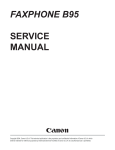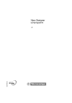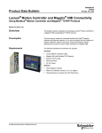
1
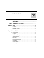
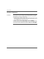
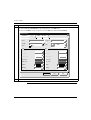
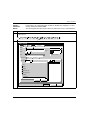
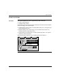
Vijeo Designer
Tutorial
35007035 04
eng
2
Table of Contents
Safety Information . . . . . . . . . . . . . . . . . . . . . . . . . . . . . . . . . . . . 5
About the Book . . . . . . . . . . . . . . . . . . . . . . . . . . . . . . . . . . . . . . . 7
Part I Vijeo Designer at a Glance . . . . . . . . . . . . . . . . . . . . . . . . 9
At a Glance . . . . . . . . . . . . . . . . . . . . . . . . . . . . . . . . . . . . . . . . . . . . . . . . . . . . . . 9
Chapter 1
General . . . . . . . . . . . . . . . . . . . . . . . . . . . . . . . . . . . . . . . . . . . . 11
At a Glance . . . . . . . . . . . . . . . . . . . . . . . . . . . . . . . . . . . . . . . . . . . . . . . . . . . . .
Software Overview . . . . . . . . . . . . . . . . . . . . . . . . . . . . . . . . . . . . . . . . . . . . . . .
Vijeo Designer's Main Tools . . . . . . . . . . . . . . . . . . . . . . . . . . . . . . . . . . . . . . . .
Installing Vijeo Designer . . . . . . . . . . . . . . . . . . . . . . . . . . . . . . . . . . . . . . . . . . .
Software Version Compatibility . . . . . . . . . . . . . . . . . . . . . . . . . . . . . . . . . . . . . .
Uninstalling Vijeo Designer . . . . . . . . . . . . . . . . . . . . . . . . . . . . . . . . . . . . . . . . .
Chapter 2
2.1
11
12
14
16
17
18
Project creation. . . . . . . . . . . . . . . . . . . . . . . . . . . . . . . . . . . . . . 19
At a Glance . . . . . . . . . . . . . . . . . . . . . . . . . . . . . . . . . . . . . . . . . . . . . . . . . . . . .
Creation of Panels. . . . . . . . . . . . . . . . . . . . . . . . . . . . . . . . . . . . . . . . . . . . . . . .
At a Glance . . . . . . . . . . . . . . . . . . . . . . . . . . . . . . . . . . . . . . . . . . . . . . . . . . . . .
Description of Requirement. . . . . . . . . . . . . . . . . . . . . . . . . . . . . . . . . . . . . . . . .
Project Construction Steps . . . . . . . . . . . . . . . . . . . . . . . . . . . . . . . . . . . . . . . . .
The Application at a Glance . . . . . . . . . . . . . . . . . . . . . . . . . . . . . . . . . . . . . . . .
Starting Vijeo Designer . . . . . . . . . . . . . . . . . . . . . . . . . . . . . . . . . . . . . . . . . . . .
Basic Settings . . . . . . . . . . . . . . . . . . . . . . . . . . . . . . . . . . . . . . . . . . . . . . . . . . .
Creating Variables. . . . . . . . . . . . . . . . . . . . . . . . . . . . . . . . . . . . . . . . . . . . . . . .
Creation of ‘Tank’ Panel . . . . . . . . . . . . . . . . . . . . . . . . . . . . . . . . . . . . . . . . . . .
Numeric and Textual Display . . . . . . . . . . . . . . . . . . . . . . . . . . . . . . . . . . . . . . .
Graphical Object . . . . . . . . . . . . . . . . . . . . . . . . . . . . . . . . . . . . . . . . . . . . . . . . .
Creation of a Recipe . . . . . . . . . . . . . . . . . . . . . . . . . . . . . . . . . . . . . . . . . . . . . .
Creation of "Curves" Panel . . . . . . . . . . . . . . . . . . . . . . . . . . . . . . . . . . . . . . . . .
Creation of "Alarms" Panel . . . . . . . . . . . . . . . . . . . . . . . . . . . . . . . . . . . . . . . . .
Creating a Script . . . . . . . . . . . . . . . . . . . . . . . . . . . . . . . . . . . . . . . . . . . . . . . . .
Simulation . . . . . . . . . . . . . . . . . . . . . . . . . . . . . . . . . . . . . . . . . . . . . . . . . . . . . .
19
21
21
22
23
24
28
29
31
35
39
43
51
56
58
62
65
3
Chapter 3
Project Download. . . . . . . . . . . . . . . . . . . . . . . . . . . . . . . . . . . . 67
At a Glance . . . . . . . . . . . . . . . . . . . . . . . . . . . . . . . . . . . . . . . . . . . . . . . . . . . . . 67
Validating, Building, and Correcting Errors . . . . . . . . . . . . . . . . . . . . . . . . . . . . . 68
Downloading a Project . . . . . . . . . . . . . . . . . . . . . . . . . . . . . . . . . . . . . . . . . . . . . 70
Index
4
. . . . . . . . . . . . . . . . . . . . . . . . . . . . . . . . . . . . . . . . . . . . . . . 73
Safety Information
§
Important Information
NOTICE
Read these instructions carefully, and look at the equipment to become familiar with the
device before trying to install, operate, or maintain it. The following special messages
may appear throughout this documentation or on the equipment to warn of potential
hazards or to call attention to information that clarifies or simplifies a procedure.
The addition of this symbol to a Danger or Warning safety label indicates
that an electrical hazard exists, which will result in personal injury if the
instructions are not followed.
This is the safety alert symbol. It is used to alert you to potential personal
injury hazards. Obey all safety messages that follow this symbol to avoid
possible injury or death.
DANGER
DANGER indicates an imminently hazardous situation, which, if not avoided, will
result in death, serious injury, or equipment damage.
WARNING
WARNING indicates a potentially hazardous situation, which, if not avoided, can result
in death, serious injury, or equipment damage.
CAUTION
CAUTION indicates a potentially hazardous situation, which, if not avoided, can result
in injury or equipment damage.
35007035 04 03/2006
5
Safety Information
PLEASE NOTE
Electrical equipment should be serviced only by qualified personnel. No responsibility is
assumed by Schneider Electric for any consequences arising out of the use of this
material. This document is not intended as an instruction manual for untrained persons.
© 2005 Schneider Electric. All Rights Reserved.
6
35007035 04 03/2006
About the Book
At a Glance
Document Scope
This manual introduces you to the fundamentals of Vijeo Designer, a software
package you need to use when you develop and configure applications for the
XBT G/XBT GT families of HMI panels.
It is written to help new users get started and as a quick reference for users who are
already familiar with the software. For detailed descriptions of the software’s feature
and functions, refer to the Vijeo Designer online help.
Related
Documents
User Comments
35007035 04 03/2006
Title of Documentation
Reference Number
Vijeo Designer User Manual
included on the Vijeo Designer CDROM
Vijeo Designer Uni-Telway Driver
included on the Vijeo Designer CDROM
Magelis XBTG Modbus TCP/IP Driver
included on the Vijeo Designer CDROM
Magelis XBTG Modbus RTU Driver
included on the Vijeo Designer CDROM
Magelis XBTG Modbus Plus Driver
included on the Vijeo Designer CDROM
We welcome your comments about this document. You can reach us by e-mail at
[email protected]
7
About the Book
8
35007035 04 03/2006
Vijeo Designer at a Glance
I
At a Glance
Purpose of this
section
This section describes the software’s main functions and installation.
What's in this
Part?
This part contains the following chapters:
35007035 04 03/2006
Chapter Chapter Name
Page
1
General
11
2
Project creation
19
3
Project Download
67
9
Vijeo Designer at a Glance
10
35007035 04 03/2006
General
1
At a Glance
Purpose of this
chapter
This chapter describes the Vijeo Designer software application.
What's in this
Chapter?
This chapter contains the following topics:
35007035 04 03/2006
Topic
Page
Software Overview
12
Vijeo Designer's Main Tools
14
Installing Vijeo Designer
16
Software Version Compatibility
17
Uninstalling Vijeo Designer
18
11
General
Software Overview
About Vijeo
Designer
Minimum System
Requirements
Vijeo Designer is a state-of-the-art software application with which you can create
operator panels and configure operating parameters for human machine interface
(HMI) devices. It provides all the tools needed to design an HMI project, from the
data acquisition to the creation and display of animated drawings.
Processor
Intel Celeron 566 MHz or faster (Pentium III 1GHz or faster
recommanded)
Memory
128 MB of RAM (512 MB or more recommended)
Available Disk Space 400 MB or more on hard disk
Features
Operating system
Windows 2000 or XP (english, french, gernan, italian or spanish)
Web browser
Internet Explorer 5.0 or later
Data reuse
Vijeo Designer uses two types of data:
z
z
internal data created in the user application
data provided by external devices such as PLCs and remote I/O modules
Graphical objects, scripts, and panels created with Vijeo Designer can be saved in
the Toolchest (See Vijeo Designer's Main Tools, p. 14) so that they can be reused in
other projects. The ability to reuse this data can help you optimize the development
of new applications and standardize screens in applications that are co-developed.
Multi-PLC connectivity
With Vijeo Designer you can configure your HMI panel to simultaneously
communicate with several different Telemecanique and third-party devices.
HMI screen creation
Vijeo Designer enables you to create dynamic screens for the HMI panel. It
combines various functions such as moving objects, zooms, level indicators, on/off
indicators, and switches in a simple application. Animated symbols can be used to
build and edit a graphical screen very simply.
Scripts
Vijeo Designer provides a script feature so that you can reuse building blocks or full
sequences from one application in other projects.
12
35007035 04 03/2006
General
Reports
Vijeo Designer incorporates an advanced function that simplifies the management
of variables used in the animation screens. Working in a Property Inspector window
(See Vijeo Designer's Main Tools, p. 14), you can configure or modify the variables
and characteristics of objects.
Multi-language messaging
Vijeo Designer can store the alarm messages or text objects for the same
application in more than 10 different languages. A simple selection from the
animation screen switches the display to the selected language.
Editing variables from other applications
Vijeo Designer can import/export variables and recipes as CSV files. Similarly,
variables created in Vijeo Designer can be exported to other applications.
Target Terminal
Models
The following HMI units are designed and configured with Vijeo Designer:
z
z
z
z
z
z
35007035 04 03/2006
XBT G2000 Series
XBT G4000 Series
XBT G5000 Series
XBT G6000 Series
XBT GT1000 Series
XBT GT2000 Series
13
General
Vijeo Designer's Main Tools
At a Glance
Vijeo Designer's main tools can be accessed from the program's main screen. Six
tool windows enable you to develop your project quickly and easily. Each window
provides information pertaining to a specific object or to the project.
You can customize your work environment by resizing or moving the windows. Icons
associated with the windows are located in the toolbar.
The Main Screen
Vijeo
Designe
The Vijeo Designer environment looks like this:
Exercise_1 - Vijeo-Frame - [Target1 - Configuration]
File
Edit
Build
HMI
Arrange
Variable
Report
Search
View
Draw
Tools
Window
Help
A
A
Vijeo
Designe
Exercise_1
Target1
Graphical Panels
1: Configuration
2: Tank
3: Chart
Application Scripts
Alarms
Popup Windows
Languages
Data Files
IO Manager
Vij.. Proj. Var. Too.
!
A..
Target1 - Configuration
1
Designe
Vijeo
Navigator
123
A
Icons for the working windows
Water level
setting
Graphic screen where work in
Alarm
progress is displayed
InfoViewer
Displays reports and Web sites
6
123
Vije
Design
Object Name
water_level_setting
Change _panel_switch
Text04
Alarm_lamp
Text03
Text01
Position
124,183x254,228
310,320x437,359
300,140x439x179
347,182x393,226
99,136x278,175
120,60x399,139
For Help, press F1
5
Exercise_1 - Vijeo-Fr.
PieGraph
Generating Code
Compiling
Romizing
Calling romizer
Romizer successful
HMI: Project 32 KB, System 2208 KB, Total Size
Build Complete
Build
X=533, Y=278
Design
Vije
démarrer
4
3
StatisticGraph
Toolchest
Order
6 123
5
4 A
3
2 A
1 A
2
FeedbackZone
GraphicsList
Property Inspector
Graphical
Name
Configuration
PanelID
1
Description
Width
640
Height
480
(153,255
Background
AA
StatisticGraph
StatisticGraph
StatisticGraph
Zoom 100%
NUM
FR
08:47
Note: Vijeo Designer appearance may be different, because all the windows can
be configured by user.
14
35007035 04 03/2006
General
Working Window
Icons
Item
The tool window icons (identified in the illustration above by the numbers 1-6) act as
toggle switches to display or hide the working windows:
Screen/Icon name Description
1
Navigator
Used to create applications. Information about each project is listed hierarchically in a
document explorer.
2
Property Inspector
Displays the selected object's parameters. When more than one object is selected, only
those parameters common to all objects are displayed.
3
Graphics list
Lists all the objects appearing in the drawing, giving their:
z creation order
z name
z position
z animations
z other associated variables
The highlighted object in the list is selected in the drawing.
Information is displayed similarly for a group of objects (i.e., order, name, position). To
display a list of the objects in a group, click +. Each object can be selected separately.
4
Feedback Zone
!
Displays the progress and results of the error check, compilation, and load.
When an error occurs, the system displays an error message or warning message. To
view the error location, double-click the error message.
5
Toolchest
A library of components (bar chart, timers, etc.) provided by the manufacturer and/or
created by you. To place a component in the drawing, select the component in the
Toolchest and drag it into the drawing.
Your own components can be exported and/or imported.
6
InfoViewer
Displays the online Help or the contents of a report
35007035 04 03/2006
15
General
Installing Vijeo Designer
Prerequisites
Installation
Procedure
Vijeo Designer software should be installed by a system administrator.
Step Action
Result
1
Close any applications running
on the desktop.
2
Insert the CD-ROM in the
computer's CD drive.
Vijeo Designer's Autorun program should
automatically start the installation program. If the
installation does not begin automatically, click Start →
Run, enter x:\SETUP.EXE in the Open box, and click
OK (where x represents your CD-ROM's drive letter).
3
Select an installation language and
click the Vijeo Designer button.
The InstallShield Wizard Welcome screen appears.
4
Click the Next button.
The terms of the license agreement are displayed.
5
Click the Yes button to accept
the terms.
The Customer Information screen appears.
6
Enter your name, your company You are prompted to enter choose an installation
name, your reference, and your folder on your computer. By default, this folder is
serial number in the Customer c:\Program Files\Schneider Electric.
Information screen. Then click
the Next button.
7
Specify an installation folder
(and click the Next button.
8
Select Program Folder and click
the Next button.
9
If you want to create a shortcut on InstallShield installs Vijeo Designer or one of its
the desktop click the Yes button. components.
10
Click the Finish button when the
installation is complete. Then
click the Exit button to return to
your desktop.
Note: At the end of the installation process, the program may ask you to restart your
computer. You must restart to update all newly installed components in the system.
16
35007035 04 03/2006
General
Software Version Compatibility
Title of Overview
Block
Once the software has been installed (See Installing Vijeo Designer, p. 16), you as
a user need to understand how this version of Vijeo Designer works with previous
versions of the software.
Note: Before starting Vijeo Designer for the first time, read the Readme.chm file,
which can be accessed from the Start → Run → Program Files → Schneider
Electric → Vijeo Designer menu.
Compatiblity
with Older
Versions of the
Software
35007035 04 03/2006
Projects created in this version of Vijeo Designer are not backward-compatible with
previous versions of the software. A new project created and opened with this
version of Vijeo Designer cannot be opened with an earlier version.
Projects created with an earlier version of Vijeo Designer are forward-compatible
with this version. However, before opening an application that was created with an
earlier version of Vijeo Designer, you should perform a complete backup of the initial
project using the export feature.
17
General
Uninstalling Vijeo Designer
Two Ways to
Uninstall the
Software
Using the
Uninstall Utility
Using the Add/
Remove
Programs Utility
18
Vijeo Designer may be uninstalled in either of two ways:
z
z
using the Uninstall utility in the software
with the Add/Remove utility on your computer’s Control Panel
Step
Action
1
Close any applications running on the desktop.
2
Click Start → Run, and enter the path to the Uninstall utility in the installation folder
for Vijeo Designer (for example, c:\Program Files\Schneider
Electric\Vijeo designer\Uninstall).
3
Click the OK button.
4
At the end of the uninstall process, restart your computer to update the system.
Step
Action
1
Close any applications running on the desktop.
2
Click Start → Settings → Control Panel.
3
Select Vijeo Designer from the list of programs and click the Remove button.
4
At the end of the uninstall process, restart your computer to update the system.
35007035 04 03/2006
Project creation
2
At a Glance
Purpose of this
Chapter
This chapter gives some procedures that describe how to produce a simple
application using Vijeo Designer's main functions.
What's in this
Chapter?
This chapter contains the following sections:
Section
2.1
35007035 04 03/2006
Topic
Creation of Panels
Page
21
19
Project creation
20
35007035 04 03/2006
Project creation
2.1
Creation of Panels
At a Glance
Subject of this
Section
This section describes the procedure to be followed to create the project screens.
What's in this
Section?
This section contains the following topics:
35007035 04 03/2006
Topic
Page
Description of Requirement
22
Project Construction Steps
23
The Application at a Glance
24
Starting Vijeo Designer
28
Basic Settings
29
Creating Variables
31
Creation of ‘Tank’ Panel
35
Numeric and Textual Display
39
Graphical Object
43
Creation of a Recipe
51
Creation of "Curves" Panel
56
Creation of "Alarms" Panel
58
Creating a Script
62
Simulation
65
21
Project creation
Description of Requirement
At a Glance
In order to discover some of the things you can do with Vijeo Designer, we are going to
develop a project. To do this, we need to describe our requirement or specifications.
The application must satisfy the following criteria:
z
z
z
z
z
22
manage the filling of a tank according to a filling setpoint and an alarm level. The
setpoint and alarm level are selected by the user from a range of presets. We will
use the recipes function for selection of presets,
empty the tank by opening/closing the bottom valve when a button is pressed,
view the setpoint values in a numeric display and as a trend graph,
have an overview of the variation in level over time. To do this, we use a trend graph,
inform the user when a threshold is exceeded via a lamp and an alarm page.
35007035 04 03/2006
Project creation
Project Construction Steps
At a Glance
The following steps must be taken and the following points addressed to create the
project manual:
z
z
z
z
z
z
z
z
z
z
z
z
35007035 04 03/2006
launch Vijeo-Designer,
create the project manual,
configure the project,
declare the variables,
create the different panels and screen jumps,
create the numeric and textual displays,
use the graphical objects from the toolchest,
create the recipe,
create the trend graphs,
create alarm management,
create a script,
generate and simulate the project.
23
Project creation
The Application at a Glance
At a Glance
The project to be designed is called "manual".
It consists of three screen pages:
z
z
z
"Tank",
"Curves",
"Alarms".
The "Tank" (See The "Tank" Panel, p. 25) panel consists of:
z
z
z
z
z
z
a tank taken from the animation toolchest,
two numeric displays (the level value and the alarm setpoint),
two types of recipe command which can be used to define the fill values and tank
level alarms,
a tank emptying valve controlled by a button,
an upper threshold alarm lamp,
and a set of buttons used to switch from one screen to another.
The "Curves" (See The "Curves" Panel, p. 26) panel consists of:
z
z
the trend graphs object in which the tank level and alarm setpoint are animated,
and a set of buttons used to switch from one screen to another.
The "Alarms" (See The "Alarms" Panel, p. 27) panel consists of:
z
z
24
the alarm object which displays the high level alarm if the tank level is higher than
the alarm setpoint,
and a set of buttons used to switch from one screen to another.
35007035 04 03/2006
Project creation
The "Tank" Panel
The tank is filled to a selected product quantity (small quantity and large quantity).
The quantity is managed by a recipe. The recipe also manages the threshold not to
be exceeded depending on the desired quantity (alarm setpoint). You can modify the
alarm setpoint by clicking (for a simulation) or by touching the numerical display for
the "level of alarm" (on the XBTG's tactile screen). The high level alarm is activated
if the tank level is higher than the alarm setpoint. Activation of the alarm causes a
lamp to light up (red if threshold exceeded). The level changes in the tank. An
emptying button enables you to empty the tank via the bottom valve. The bottom
valve is animated when you press the "emptying" button. When closed the valve is
shown in gray. When it is open it is shown in red.
The following diagram shows the "Tank" page:
1
Tank
Curves
Alarms
Small quantity
2
Medium quantity
8
Large quantity
3
Send
Small quantity
Tank Level:
Alarm level:
7
25
27
Emptying
5
4
Number
35007035 04 03/2006
6
Description
1
Screen browser button
2
High level lamp
3
Tank with animated level
4
Tank bottom valve
5
Tank emptying button
6
Data entry zone for setpoint using numerical keypad
7
Recipe selector
8
Recipe command buttons
25
Project creation
The "Curves"
Panel
In this screen, the variation in the tank level and the alarm setpoint is represented in
graphic form.
Illustration of the "Curves" panel:
1
Tank
Alarms
100
90
80
70
60
50
40
30
20
10
0
2
Number
26
Curves
Description
1
Screen browser button
2
Trend graph showing the tank level and setpoint
35007035 04 03/2006
Project creation
The "Alarms"
Panel
This screen enables you to view the state of the level alarm.
Illustration of the "Alarms" panel:
1
Tank
Message
Curves
Hour
Alarms
State
2
Number
35007035 04 03/2006
Description
1
Screen browser button
2
Alarm table for viewing active, acknowledged or elapsed/resolved alarms
27
Project creation
Starting Vijeo Designer
Procedure
28
To start Vijeo Designer, select Start \ Programs \ Vijeo Designer or double-click
the Vijeo Designer icon on the desktop.
35007035 04 03/2006
Project creation
Basic Settings
At a Glance
Configuring your project correctly is essential before you begin to create a drawing.
This project uses internal and external variables.
A project created in Vijeo Designer is a simple chain of information (database). Within a
project, the target terminals are configured and organized in a hierarchical structure.
Each target shows the hardware environment (PLC device) in which the project will be run.
Create a Project
and Configure its
Target
The following table describes the procedure to follow to create a project and select
the remote device:
Step
1
Action
This dialog box appears when Vijeo Designer is started. Click "Next" to continue.
Vijeo-Designer
Welcome to Vijeo-Designer
What would you like to do?
Create new project
Open last project
Open existing project
Don't show this dialog box again
< Back
Next >
Finish
Cancel
Note: If the above dialog box is not displayed when you start Vijeo Designer, you
must select the "Vijeo-Manager" tab in the navigator, then right-click "VijeoManager" and select "New Project".
35007035 04 03/2006
29
Project creation
Step
2
Action
z Enter the name of your project and click OK (in our case, type "Manual_V42").
z Click on Next then select module type XBT G2230.
z Click on Next, select the IP address if the model uses an Ethernet port then click
Next.
z Select the relevant driver for the device type using the Add button (in our
example, enter Schneider Electric Industrie SAS as the Manufacturer and
Uni telway as the driver) then click on Finish.
New folders (panels, scripts, alarms, popup windows, languages, data files, etc.) are
created.
Property Inspector
Target
Name
Target1
Description
Type
XBTG Series
TargetColor
256 Colors
Model
XBTG2330 (320x240)
InitialPanelID
1: Tank
Startup option
Buzzer
Enable
ToConfiguration
Top Left Corner
Download
Ethernet
Data Sharing
Ethernet
Disabled
Printer
File System
Disabled
Serialcal
Security
Input Mode
Alarm Banner
Disabled
System keypad
Note: To add another "Target" to the project, right-click "My Project" then select
"New Project".
3
30
Save your project.
35007035 04 03/2006
Project creation
Creating Variables
At a Glance
A variable is a memory address indicated by a name. Vijeo Designer handles the
following types of variables:
z
z
z
z
z
z
z
Boolean
Integer
Floating
Character string
Structure
Integer block
Floating point block
Vijeo Designer uses the variables to communicate with devices. You can also define
internal variables that will only be used by Vijeo Designer.
In our project, we are going to create three internal variables and one external
variable which communicates with a Uni-Telway device.
The following table describes the procedure to follow for creating variables:
Step
1
Action
Click the "Variables" tab in the "Navigator" window, right-click on Target1 and
select "New Variable" then the type "Discrete".
Variable List: Sort By Target Name, Filter
Target1
New Variable
New...
Paste
Ctrl+V
Import Variables
Ctrl+I
Export Variables
Ctrl+E
Properties
Alt+Enter
Discrete
Integer
Floating
String
Structure
Integer Block
35007035 04 03/2006
Designer
Vijeo
Vije.
Project
Variables
Toolchest
Floating Point Block
31
Project creation
Step
2
Action
You will now change the name of the Boolean-type "DISCRETE01" variable to
"High_level" from the variable properties window. In this window, specify the variable
source (external in this case). The variable has %M0 as its Device Address
Variable List: Sort By Target Name, Filter
Target1
High_level[%M0]
3
Designer
Vijeo
Vij...
Pro...
Var...
Too...
The "High_level" variable is an alarm. In its properties enable the Alarms function.
- Variable
Name
High_level
Description
ArrayDimension
0
DataType
Discrete
Source
External
Scan Group
Device Address
UniTelway01Device
%M0
...
Indirect Address
32
...
+ KeepHistory
Enabled
+ Alarm
Enabled
35007035 04 03/2006
Project creation
Step
4
Action
Repeat steps 1 and 2 to create the following internal variable of Discrete (Boolean)
type: "Emptying".
You have now created two Boolean variables.
Variable List: Sort By Target Name, Filter
Target1
High_level[%M0]
Emptying
Vij...
5
Vijeo
Designer
Pro..
Var...
Too...
Click the "Variables" tab in the "Navigator" window, right-click on Target1 and
select "New Variable" then the type "Integer".
Variable List: Sort By Target Name, Filter
Target1
New Variable
New...
Paste
Ctrl+V
Import Variables
Ctrl+I
Export Variables
Ctrl+E
Properties
Alt+Enter
Discrete
Integer
Floating
String
Structure
Integer Block
35007035 04 03/2006
Vijeo
Vije.
Designer
Project
Variables
Toolchest
Floating Point Block
33
Project creation
Step
6
Action
You will now change the name of the "Integer01" variable of "integer" type to "Level"
from the variable properties window. In this window, specify the variable source
(external in this case). The variable has %MW0 as its Device Address
Variable List: Sort By Target Name, Filter
Target1
High_level[%M0]
Emptying
Level[%MW0]
7
Designer
Vijeo
Vij...
Pro...
Var...
Too...
Repeat steps 5 and 6 to create the following internal variables of Integer type: "Setup".
Now, in the Variable tab, you will see this list.
Variable List: Sort By Target Name, Filter
Target1
High_level[%M0]
Emptying
Level[%MW0]
Setup
Designer
Vijeo
Vij...
Pro..
Var...
Too...
Note: It is possible to access the variable properties by double-clicking on the
variable. A window with five tabs is displayed, making variable configuration easier
to access and understand.
34
35007035 04 03/2006
Project creation
Creation of ‘Tank’ Panel
Illustration
The graphic below shows the panels to be created in this phase:
Tank
35007035 04 03/2006
Curves
Alarms
35
Project creation
Procedure
The following table describes the procedure to follow to create the panels:
Step Action
1
Click the "Project" tab in the navigator.
2
Double-click "Graphical Panels" to open the folder.
3
z Click on "1:Panel1",
z Rename "1:Panel1" as "1:Tank".
Navigator
Manual
Target1
Graphical Panel
1: Tank
2: Curves
3: Alarms
Application Scripts
Init
Decrement
alarm
Alarms
Popup Windows
Languages [Language1]
Data Files
Ressource Library
Recipes
1: TankSetting
IO Manager
UniTelway01 [COM1]
UniTelway01Equipment1
36
De Project
Vi
Vijeo.Manager
Variables
Toolchest...
4
In the "Properties" window, change the background color to light gray, which gives a color code of
"192,192,192".
5
Create two other panels using the same background colour as the Tank panel.
Right-click on Graphical Panels and select New Panel
Panel 2 is called Curves and panel 3 is called Alarms.
35007035 04 03/2006
Project creation
Create a Panel
Browser Button
The following table describes the procedure to be followed to create a button used
to jump between pages:
Step Action
1
Select the "Switch" icon in the toolbar and draw an area on the panel where the button will be placed.
A
123
A
A..
To define an area where the object is to be placed, simply:
z left-click in the screen where you wish to position your object,
z release the left mouse button,
z drag the mouse to obtain the desired size of your object on the screen,
z left-click in the screen a second time once you are happy with the object size,
35007035 04 03/2006
37
Project creation
Step Action
2
When the "Switch Settings" window is displayed, in the General tab:
z enter the name "Button_tank",
z select the category primitive and the button style 00002,
z When Touch , select Panel in Operation, select Change Panel for Tank (Id=1) then click on Add.
Switch Settings
General
Color
Label
Visibility
Mode
Switch
Name
Button_tank
State
Advanced
Category
Switch with Lamp
Primitive
00002
Style
[Up]
Reverse On Touch
Lamp
When Touch
Operation
While Touch
When Release
Panel
Change Panel[1]
Change Panel
Panel ID:
1
1: Tank
Previous Panel
Apply
Add >
OK
38
Cancel
Help
3
In the Color tab, select a dark green (code 0.128.0) for the foreground color.
4
In the Label tab, the label type must be static and you must enter Tank in the free text field.
5
Click on OK to confirm the configuration.
6
Repeat the operation for the buttons for the Curves panel (Id=2) and the Alarms panel (Id=3).
7
At this stage, in the current panel you will now have 3 buttons enabling you to jump between pages. Select
these 3 buttons to copy (Ctrl+C) and paste (Ctrl+V) them into the two other panels.
35007035 04 03/2006
Project creation
Numeric and Textual Display
Illustration
The graphic below represents the Tank screen phase to be created:
Tank
Curves
Tank level:
Alarm level:
35007035 04 03/2006
Alarms
25
27
39
Project creation
Create Text
The following table describes the procedure to be followed to create text:
Step Action
1
Select the "Text" icon in the toolbar and draw an area on the screen where the text will be placed.
A
2
123
A
A..
The Text Editor window is displayed. Configure the text properties as shown in the screen below and click on OK:
Text Editor
Language:
Font:
Font Style:
1: Language1
Vijeo Modern 8x13
Font Width: 8
Normal
Font Height: 13
Tank level:
OK
40
Cancel
3
In the "Properties" window, change the Text Color to black 0,0,0.
4
Do the same for the text Alarm level.
35007035 04 03/2006
Project creation
Create a Numeric
Indicator
The following table describes the procedure to follow to create a numeric display:
Step Action
1
Select the "Data Display" icon in the toolbar and draw an area on the screen where the numeric window will be placed.
A
2
123
A
A..
The Numeric Display Settings window is displayed. Configure the properties as shown in the screen below:
Numeric Display Settings
General
Input Mode
Color
Advanced
Visibility
NumericalDisplay01
Name
Data
Type
Integer
Variable
00026
Style
Floating
Level
Display Digits 3
Zero Suppress
Display Zero(s)
Language
Font
Font Style
Format
.
0
Dec.
1: Language1
Vijeo Modern 6x10
Font Width
6
Bold
Font Height
10
123
Alignment
OK
3
Cancel
Help
In this window, from the "General" tab:
Click the
icon then:
z double-click on the "Level" variable then on OK in the expression editor,
z enter 3.0 in the "Display Digits" field,
z Click OK.
35007035 04 03/2006
41
Project creation
Step Action
4
In the "Color" tab:
z select the color dark blue 0,128,128 for the "Back Color".
5
Click OK.
6
Repeat thse steps for the ‘Setup’ variable.
For the ‘Setup’ variable, you must authorize the user to change its value. To do this, check Enable Input Mode
in the Input Mode tab. The option Display Popup Keypad is automatically selected. It enables a numerical
keypad to be displayed on the product screen when the user enters Edit variable mode.
7
Save your project.
Note: You can access and modify an object's settings in the "Properties" window.
42
35007035 04 03/2006
Project creation
Graphical Object
Illustration
In this section, the user adds the tank, the bottom valve, the valve piping, and the
valve command button and high level indicator. After performing the steps below,
the screen looks like this:
Tank
Curves
Level of the tank :
Level of alarm :
Alarms
25
27
Emptying
35007035 04 03/2006
43
Project creation
Import an Object
from the
Toolchest
The following table describes the procedure to be followed to use an object from the
toolchest which provides a schematic representation of the tank:
Step Action
1
The tank can be found in the toolchest tab. It is located in the Tank Graph directory. Take the object
TankGraph_0001 and drag-and-drop it into the Tank panel. Resize the object as required by dragging any of
the points that appear around the object when you select it.
Navigator
Toolchest
Text Display
Image Library
Dial
Keypads
Logging Trend Graph
DateTime
Diagnostics
Other
Circular Graph
Data Graph
Bar Graph
Tank Graph
Pie Graph
Models
Recipes
User
Lamps
2
D Project
V
Vijeo.Manager
Variables
Toolchest...
In the "Properties" window click on the ..... icon. The Variable List window is displayed. Double-click on the
‘Level’ variable to animate the tank level.
44
35007035 04 03/2006
Project creation
Create a Line
The following table describes the procedure to be followed to create a line
representing the piping of the bottom valve:
Step Action
1
Select the "line" icon from the tool bar and draw an area on the screen where the line will be placed (in our
example, it starts at the bottom of the tank and ends at the bottom of the screen). Adjust the position of the
line (or object) using the arrow keys on your keyboard.
A
2
123
A
A..
In the "Properties" window, enter:
z "0,0,0" black as the line color,
z "4" as the line thickness.
35007035 04 03/2006
45
Project creation
Create Valve
In this project a polygon shape is used to represent the valve. It is animated
differently according to whether it is open (green) or closed (gray).
The following table describes the procedure to be followed to create the valve:
Step
1
Action
Select the "Polygon" icon in the toolbar and use it to draw a valve, defining an area on the screen where the
valve will be placed.
A
2
123
A
A..
The Animation Properties window is displayed. Configure the properties as shown in the screen below:
Animation Properties
Color
Fill
Fore Color
Size
Position
Back Color
Enable Fore Color Animation
Rotate
Touch
Visib.
Line Color
Data Type:
Discrete
Emptying
Value
Color
OFF
ON
OK
3
Cancel
Apply
Help
In this window, in the "Color" tab:
z check Enable Fore Color Animation,
Click the
icon then:
z double-click on the Discrete "Emptying" variable then on "OK",
z change the OFF and ON colors (OFF in gray and ON in green).
4
46
Click OK.
35007035 04 03/2006
Project creation
Create Warning
Signal
In this project the lamp is used for signaling. It is animated depending on whether
the alarm is triggered (red) or untriggered (grey) for "High_level".
The following table describes the procedure to be followed to create the lamp:
Step Action
1
Select the "Lamp" icon in the toolbar and use it to draw a Lamp, defining an area on the screen where the lamp
will be placed.
A
2
123
A
A..
In this window, from the "General" tab:
Click the
icon then:
z select the "Discrete" "High_level" variable,
z retain the lamp style 10001.
35007035 04 03/2006
47
Project creation
Step Action
3
In the "Color" tab:
z select a dark gray ‘128.128.128’ for the foreground color of the OFF state,
z select a red ‘255.0.0’ for the foreground color of the ON state combined with fast blink,
LED-Parameters
General
Color
Name
02Lamp
Variable
High-level
Label
View
Category
Primitive
Style
State
Off
On
Text color
Text color
3D color
3D color
Border color
Border color
Front color
Front color
Back color
Back color
Pattern
Aucun
1:
Pattern
Aucun
1:
Blinking
Aucun
None
Blinking
Aucun
None
OK
4
48
10001
[Off]
Cancel
Help
Click OK.
35007035 04 03/2006
Project creation
Create a
Command
Button
In this project, the "emptying" button enables or disables the "emptying". It is also
used to animate the bottom valve.
The following table describes the procedure to be followed to create a command button :
Step Action
1
Select the "Switch" icon in the toolbar and use it to draw a rectangle, defining an area on the screen where
it will be placed.
A
2
123
A
A..
The Switch Settings window is displayed. Configure the properties as shown in the screen below:
Switch Settings
General
Label
Color
Mode
Switch
Name
Switch03
State
Visibility
Advanced
Switch with Lamp
Category
Primitive
00003
Style
[Up]
Lamp
Reverse On Touch
When Touch
Operation
While Touch When Release
Bit
Bit Toggle [Emptying
Operation
Set
Reset
Toggle
Momentary ON
Momentary OFF
Destination
Emptying
Apply
Add >
OK
35007035 04 03/2006
Cancel
Help
49
Project creation
Step
3
Action
In the General window:
z select 00003 as the switch style.
in the "When Touch" tab, click on the
icon and:
z select the "Discrete" "Emptying" variable,
z select Toggle which will switch ON the Emptying bit when the button is first pressed and switch it OFF
when the button is pressed again.
z click on Add to confirm the selection.
4
In the "Label" tab:
z select static for the label type,
z enter ‘Emptying’ in the data entry window,
50
5
In the "Color" tab:
z select the white ‘255.255.255’ as the foreground color,
z select the black ‘0.0.0’ as the text color.
6
Click OK.
35007035 04 03/2006
Project creation
Creation of a Recipe
Illustration
This sections explains two ways of implementing recipe commands:
z
z
using a command button,
using the recipe selector.
In this project, we have created 3 recipes to determine the level and alarm setpoint
values according to the selected recipe:
z
Small quantity is the first recipe. It is used to fill the tank to 25% of its capacity and
sets an alarm level at 27%,
z
Medium quantity is the second recipe. It is used to fill the tank to 50% of its
capacity and sets an alarm level at 52%,
z
Large quantity is the third recipe. It is used to fill the tank to 80% of its capacity
and sets an alarm level at 82%.
After performing the steps below, the completed screen looks like this:
Tank
Curves
Alarms
Small quantity
Medium quantity
Large quantity
Send
Small quantity
Tank level :
Alarm level :
25
27
Emptying
35007035 04 03/2006
51
Project creation
Create the
Recipe
Step
The following table describes the procedure to be followed to create the recipe:
Action
1
In the project tab, right-click on "Recipe".
2
Create a new recipe group.
3
Rename the new recipe group ‘Tanksetting’.
4
Configure the recipe names as follows:
Recipes
recipe1
recipe2
Click to resize window
recipe3
Recipes
ID
Access Rights
Language1
Small
1
0
Small quantity
Medium
2
0
Medium quantity
Large
3
0
Large quantity
z Right-click on Recipes and select New Recipe to create recipe 2
z Right-click on Recipes and select New Recipe to create recipe 3
z Click on the arrow, as shown in the graphic, to expand the window,
z Rename recipe 1 as Small and, in the Language 1 column, enter Small quantity,
z Rename recipe 2 as Medium and, in the Language 1 column, enter Medium quantity,
z Rename recipe 3 as Large and, in the Language 1 column, enter Large quantity,
3 recipes will now have been created.
5
Configure the recipe names as follows:
Recipes
Small
Medium
Large
Click to select all recipes
z Click on the arrow, as shown in the above graphic, to minimize the window,
z Click on Recipes, as shown in the graphic, to select all the recipes and perform the following configuration
steps,
52
35007035 04 03/2006
Project creation
Step
3
Action
Configure the recipes as follows:
Ingredients Varia...
Label
Min
Max
Small
Medium
Large
1
Level
Level
Editable
0
100
25
50
80
2
Setup
Alarm setup
0
100
27
52
82
Fill in line 1 by double-clicking to enter data,
Add an ingredient by right clicking on line 1 and selecting New Ingredient which enables you to create line 2
Fill in line 2 by double-clicking to enter data,
6
Save your project.
35007035 04 03/2006
53
Project creation
Create ButtonOperated Recipe
Command
In this project, three recipes are declared so you need to design and configure three
command buttons.
The following table describes the procedure to be followed to create a command
button for a recipe:
Step Action
1
Select the "Switch" icon in the toolbar and use it to draw a rectangle, defining an area on the screen where
it will be placed.
A
2
123
A
A..
The Switch Settings window is displayed. Configure the properties as shown in the screen below:
Switch Settings
General
Label
Color
Mode
Switch
Name
Switch04
State
Visibility Advanced
Switch with Lamp
Category
Primitive
00002
Style
[Up]
Lamp
Reverse On Touch
When Touch While Touch When Release
Operation
Word
Word Set [RecipeGroup
Word Set [RecipeGroup
Source
1
Operation
Assign
AND
Add
OR
Subtract
Exclusive OR
Destination
RecipeDefaultControl.recipeNumber
Apply
Add >
OK
54
Cancel
Help
35007035 04 03/2006
Project creation
Step Action
3
In the General window:
z select 00002 as the switch style.
from the "When Touch" tab:
z select a Word operation,
z Enable 1 in Source.
z in Destination, click on the
icon and select RecipeDefaultControl.RecipeNumber.
z click on Add to confirm selection of recipe number 1.
z Repeat the operation, enabling for source 1 the destination RecipeDefaultControl.RecipeOperation,
z click on Add to confirm the choice to send a recipe command.
4
In the "Label" tab:
z select static for the label type,
5
In the "Color" tab:
z select the yellow ‘255.255.0’ as the foreground color,
6
Click OK.
7
Save your project.
z enter ‘Small quantity’ in the data entry window,
Repeat all these steps to create each of the command buttons for the Medium and
Large recipes using this assignment table:
Small
RecipeDefaultControl.RecipeNumber (Recipe number) 1
Medium
Large
2
3
RecipeDefaultControl.operation (recipe operation)
1
1
1
Button color and color code
yellow
255.255.0
salmon pink
255.128.64
brown
128.128.0
Button label
Small quantity
Medium quantity
Large quantity
Create a Recipe
Selector
35007035 04 03/2006
The recipe selector can be found in the toolchest. It is located in the recipe directory.
In the "Tank" panel, drag in the "Recipeselect" object and the "send" object.
55
Project creation
Creation of "Curves" Panel
Illustration
The ‘Curves’ panel and the ‘page jump’ button group have already been created in
(See Create a Panel Browser Button, p. 37). The purpose of this section is to import
the trend graph object and to configure the "Level" and "Setup" variables to be able
to view their values as graphs.
The graphic below represents the screen to be created:
Tank
Curves
Alarms
100
90
80
70
60
50
40
30
20
10
0
Create Trend
Graph
The following table describes the procedure to be followed to create the trend graph
for the ‘Curves’ panel:
Step Action
1
Select the "Trend Graph" icon in the toolbar and draw an area on the panel where the object will be placed.
A
56
123
A
A..
35007035 04 03/2006
Project creation
Step Action
2
Configure the trend graphs in the properties window:
z enter the "Level" variable for channel1,
z Enable channel2 and select the "Setup" variable.
Properties
Trend_Graph
Name
Hi
Left
Width
Height
Description
PlateColor
BorderColor
GraphSettings
RangeSettings
DataAxisLabel
DataAxisScale
DataGridLine
TimeAxisScale
TimeAxisGridLine
Channel1
Variable
DisplayFormat
Track
Mark
Color
OutOfRangeColor
Channel2
Variable
DisplayFormat
Track
Mark
Color
OutOfRangeColor
Channel3
Channel4
Channel5
Channel6
Channel7
Channel8
SaveDefaults
RestoreDefaults
3
Trend_Graph
40
41
259
180
(0,0,0)
(255,255
Enabled
Enabled
Enabled
Enabled
Enabled
Enabled
Level
Line
Disabled
Disabled
Disabled
Enabled
Setup
Line
Disabled
Disabled
...
...
Disabled
Disabled
Disabled
Disabled
Disabled
Disabled
Disabled
>>>
<<<
Save your project.
35007035 04 03/2006
57
Project creation
Creation of "Alarms" Panel
Illustration
The Alarms panel and the ‘page jump’ button group have already been created in (See
Create a Panel Browser Button, p. 37). The purpose of this section is to demonstrate
how to use the alarm object and configure it to view alarms on this screen.
The graphic below represents the Alarms screen page to be finalized:
Tank
Message
58
Curves
Hour
Alarms
State
35007035 04 03/2006
Project creation
Import and
Configure Alarm
Object
The following table describes the procedure to be followed to use the alarm table:
Step Action
1
Select the "Alarm Summaries" icon in the toolbar and draw an area on the screen where the object will be placed.
A
2
123
A
A..
Double-click on the object to configure in the Alarm Summary Parameters window.
In the Basic tab:
z select the Log display mode to display changes in alarm state (active, acknowledged, elapsed).
Alarm Summary Settings
Basic
Font
Color
Name
Column Display
Buttons
AlarmSummary01
Description
Date Format
yy/mm/dd
Time Format
24:00:00
Alarm Group
AlarmGroup1
Scroll Direction
Up
Display Mode
Log
Cursor Type
Arrow
Sort By
Time
Show Column Title
Enable Action
Direct Selection
Cursor On Action
AutoCursor
OK
Cancel
Help
Note: The column display may be configured as required. In this Alarms page, we
have chosen to display the message with a column width of 120, and the alarm
date and time with column widths of 80.
35007035 04 03/2006
59
Project creation
Configure Alarm
Group
The following table describes the procedure to be followed to configure the alarm
group:
Step Action
1
Click the "Project" tab in the navigator.
Navigator
Manual
Target1
Graphical Panel
1: Tank
2: Curves
3: Alarms
Application Scripts
Init
Decrement
alarm
Alarms
Popup Windows
Languages [Language1]
Data Files
Ressource Library
Recipes
1: TankSetting
IO Manager
UniTelway01 [COM1]
UniTelway01Equipment1
60
D Project
V
Vijeo.Manager
Variables
Toolchest...
2
Double-click "Alarms" to open the folder.
3
Click on "AlarmGroup1" to open the alarm group configuration window.
35007035 04 03/2006
Project creation
Step Action
4
To the High_level alarm, add the message "Tank in high level" as shown in the following screen:
Alarm Group Setting
Variable
High_level
Alarm Group
AlarmGroup1
Data Source Device Address
External
%M0
Message
Tank in high level
Configuration
Variable
AlarmSummary01
Alarm Groups
AlarmGroup1
Device Address
%M0
...
Language
1: language1
Message
Tank in high level
...
...
When the alarm is triggered, "Tank in high level" will be displayed in the message column.
5
Save your project.
35007035 04 03/2006
61
Project creation
Creating a Script
At a Glance
In Vijeo Designer, a script can be used to automate some of a communication
program's tasks. You can use a script to define a procedure that runs when a
condition is met.
You can then add a function that is not available in a drawing's properties.
In this project, we create three scripts:
z
z
z
Create the Init
Script
Init, which is triggered when the product is powered up. It is used to select recipe
number 1.
Decrement, which is triggered on activation of the "Emptying" variable at a
frequency of 0.3 seconds. It is used to simulate emptying of the tank.
Alarm, a periodic script which manages the ‘High_level’, alarm. The condition
which triggers the alarm is normally a condition written to the PLC. For the
purposes of this tutorial, this variable is animated internally.
The following script is executed once (on startup).
The following table describes the procedure to be followed to create the "Init" script:
Step Action
1
In the navigator window, click on the "Project" tab , then right-click on "Application
Script" and select "New Script"
2
Select "On Startup" in the "Trigger" field of the "Properties" window:
Properties
Panel Script
Name
init
Trigger
On Startup
z rename "script_1" as "Init".
3
Click on "Init" to open the script editor window and enter the following program:
//Set Recipegroup
RecipeControlDefault.RecipeGroupNumber.write(1);
Note: To insert a variable in a script, you can right-click and select Insert, Variable
then the command element associated with the variable
62
35007035 04 03/2006
Project creation
Create the
Decrement
Script
The following script is executed every 0.3 seconds if the "Emptying" variable is
enabled. It is used to simulate emptying of the tank.
The following table describes the procedure to be followed to create the
"Decrement" script:
Step
Action
1
In the navigator window, click on the "Project" tab , then right-click on "Application
Script" and select "New Script"
2
Select "Conditional" in the "Trigger" field of the "Properties" window. In the
Trigger Condition field, select While True, for the Frequency enter 1 and for the
Trigger Variable "Emptying":
Properties
Application Script
Name
decrement
Trigger
Conditional
Frequency [secs]
1
Scheduling
Low
Trigger Variable
Emptying
Trigger Condition
While True
z rename "script_2" as "Decrement".
3
35007035 04 03/2006
Enter the following program:
//creating temporary variable int tmp;
int tmp;
//Set value of Level in tmp
tmp = Level.getIntValue ();
//If value of level>0
if (tmp>0)
{
//then decrement tmp
tmp --;
//Then write tmp’s value in Level variable
Level.write ( tmp );
}
63
Project creation
Create the Alarm
Script
The following script is executed periodically every second. It manages the
"High_level" alarm. The condition which triggers the alarm is normally a condition
written to the PLC. For the purposes of this tutorial, the "High_level" variable is
animated internally.
The following table describes the procedure to be followed to create the "Alarm"
script:
Step Action
1
In the navigator window, click on the "Project" tab , then right-click on "Application
Script" and select "New Script"
2
Select "Periodic" in the "Trigger" field of the "Properties" window, specifying a
Frequency of 1.0 second:
Properties
Application Script
Name
Alarm
Trigger
Periodic
Frequency [secs]
1
Scheduling
Low
z rename "script_3" as "Alarm".
64
3
Enter the following program:
//If Level > Setup of alarm
if (Level.getIntValue() > Setup.getIntValue())
//Then Alarm (High_level) actived else alarm desactived
High_level.write(1);
else
High_level.write(0);
4
Save your project.
35007035 04 03/2006
Project creation
Simulation
Simulating your
Project
The simulation function can be used to display your project without downloading it
to an XBT G terminal. It is a good way to check and validate your project, and make
sure things are the way you want.
Start Simulation
Use the following procedure to run the simulation and check your project:
Step Action
1
35007035 04 03/2006
Result
Click the Project tab in the Navigator
window.
2
Right-click Target 1.
3
Select Start Device Simulation.
The main screen of your project appear
4
Test your project as it is so far.
It should behave like the Exercice_1
project presented at the beginning of the
Tutorial. For example:
z Choose a recipe. Does the value
appear on the tank graphically and in
the numeric display?
z Click on the numeric display (level of
alarm) and enter number 10 with the
keypad that pops up. When the alarm
appears, does the light blink?
z Click the navigation button to move to
the second screen. Do the values
appear on the curve?
z Click on the alarms button to move to
the third screen. Do you get there?
z Return to the first screen. Click on
emptying button. Does the tank empty?
5
If you find that some elements are not
To stop the simulation, press either
CTRL+Z or ALT+F4 or click on the Close working properly, go back to the
appropriate panel, select the element(s)
icon of the simulation windows.
and review the properties.
6
When everything is fine, go to the next
procedure to trigger the alarm.
Note: When re-testing your project after
making corrections, you must close the
simulation before running a new one.
65
Project creation
66
35007035 04 03/2006
Project Download
3
At a Glance
Purpose of this
Chapter
This chapter describes the different project build types and the various project
download modes.
What's in this
Chapter?
This chapter contains the following topics:
35007035 04 03/2006
Topic
Page
Validating, Building, and Correcting Errors
68
Downloading a Project
70
67
Project Download
Validating, Building, and Correcting Errors
Types of Data
Transfer
Use one of the following methods to transfer a customer application to a terminal (or
perform a local simulation):
Type
Procedure
Ethernet
The application produced by the built project* is transferred to products
equipped with an Ethernet port over the network.
Tool port
Data produced by the built project* is transferred to the device connected
to the PC using XBT ZG915 or XBT ZG925 cables.
CompactFlash
card
Data produced by the built project* (on a PC equipped with a PCMCIA card
reader) is transferred by copying to a CompactFlash card. The card is then
inserted in the terminals.
Local simulation Data produced by the built project* is stored locally for simulating the
application during its fine-tuning phase.
* Data created using the Build function.
Validating the
Target
To make sure that all the parameters of the project you want to build are present and
correct, use the Build → Validate all command from the main menu.
Building the
Target
The objective is to build a program that can be run directly by the XBT G panel from
the project created with the Vijeo Designer graphical editor.
Before starting the build, use the Build → Clean All command. This command
cleans the project folder for each target and/or project so that they are free of
unnecessary files.
After cleaning the target folders, use the Build → Build All command to build your target.
Vijeo Designer can build a program in any of four possible ways:
68
Type
Procedure
Build
Rebuilds the project completely and optimizes the results file. Although
creation is quicker than when using the Build function.
Quick Build
Builds only the data updated since the previous version was built, and
optimizes the results file.
Start simulation
Rebuilds the project completely and refreshes the resulting file. When the
build is complete, the simulation starts.
Download
Before download, the target is validated and built. If no errors are detected,
the user application files are transferred to the target machine.
35007035 04 03/2006
Project Download
Error Correction
When the build process completes, the Feedback zone window opens
automatically, and all detected errors and warnings are displayed. Errors are
displayed in red, and warnings are displayed in yellow. When there are no errors or
warnings, the result is displayed in green.
To view detailed information on a specific error or warning, double-click on that error
or warning message.
35007035 04 03/2006
69
Project Download
Downloading a Project
Data Download
Types
When you send an application to its target, you use a download method. Several
download methods may be used:
z
z
z
downloading over an Ethernet network
a file system method, where data is downloaded to a CF card
using the unit's serial port to download directly to the target.
Select the method you want to use in the Target area of the Property Inspector window.
For more information, see the online help.
Note: At this stage, you can test your project on an XBT G panel. Keep in mind that
the project will behave just as it did when it was simulated on the PC (See
Simulating your Project, p. 65). To implement a real application, the input value
should come from a field sensor, not from the keyboard.
70
35007035 04 03/2006
Project Download
Download
Procedure
Use the following procedure to download an application to an XBT G target:
Step Action
1
Connect one end of the download cable to the XBT G tool connector or to an Ethernet
cable connector and the other end to the COM1 or Ethernet port on your computer.
XBT G2110/2120/2220/4320: only tool connector (serial)
Other XBT G units allow you to choose an Ethernet or tool connector connection.
2
Click the Project tab in the Navigator window, and click Target1.
3
In the Download field of the Property Inspector window, select either Ethernet or Serial.
Property Inspector
Target
Name
Target1
Description
Type
XBT G Series
TargetColor
256 Colors
Model
InitialPanelID
XBT G2330 (320x240)
1: Tank
Startup option
Buzzer
Enable
ToConfiguration
Top Left Corner
Download
Ethernet
Data Sharing
Ethernet
Disabled
File System
Disabled
Serialcal
Printer
Security
Input Mode
Alarm Banner
Disabled
System keypad
4
a. For an Ethernet download, be sure to enter your:
z IPAddress
z SubnetMask
z DefaultGateway
b. For a serial download, be sure to enter a:
z COM port
z baud rate
35007035 04 03/2006
5
In the Navigator window, and click Target1. then click right to select Download.
6
Check your XBT G unit to see if the application is displayed correctly.
Note: If an error message appears in the Feedback zone, the download has failed.
You need to solve the problem before trying to download data again. Double-click on
an error displayed in the Feedback zone to locate the error position.
71
Project Download
Exit Vijeo
Designer
72
Before you exit Vijeo Designer, save your project. Then select File → Exit from the
main menu.
35007035 04 03/2006
B
AC
Index
B
H
building, 68
HMI, 12
HMI panels that use Vijeo Designer, 13
C
Configuration, 29
connectivity, 12
I
Installation, 16
D
M
data reuse, 12
data transfer, 68
Display, 39
downloading a project, 70
messaging
in multiple languages, 13
multi-language messaging, 13
E
editing variables, 13
Ethernet, 68
G
generation, 68
Graphical Panel
Alarm, 58
Curves, 56
Tank, 35
graphical panel, 12
35007035 04 03/2006
O
Object, 43
R
Recipe, 51
reports, 13
reusing data, 12
S
Script, 62
scripts, 12
simulation, 65
Starting Vijeo Designer, 28
73
Index
T
target devices, 13
U
Uninstall, 18
V
variable editing, 13
Variables, 31
74
35007035 04 03/2006