1
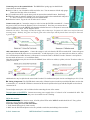
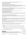
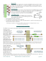
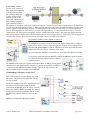
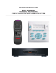
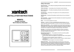
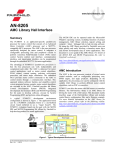
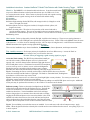
Installation Instructions
Azatrax HexDetex™ Model Train Detector with Grade Crossing Trigger
MRD6X
What it is: The MRD6X is a six-channel model train detector. It can detect model trains
at up to six different locations on the layout and activate up to six LEDs or six 5-volt,
low current electronic circuits. If the sensors are placed on a track with a grade crossing,
the MRD6X can turn a grade crossing circuit on and off with realistic timing.
Kit contents:
★ Circuit board
★ Infrared light-emitting diodes (IR LEDs) with orange & white (2 ft length) or red &
white (6 ft length) wire leads
★ Infrared photo receivers with green & white (2 ft length) or blue & yellow (6 ft
length) wire leads
★ Plastic mounting tubes. The tubes are for protection of the sensor leads and to
provide mounting support. They are not essential for detector operation and may be
shortened or removed entirely to best fit your situation. Just use caution to avoid damaging the leads.
★ Mounting screws
How it works: Trains are detected by infrared (IR) light, invisible to the human eye. There are two sensing elements at
each track location - an IR LED light source paired with an IR photo receiver. Yellow LEDs on the MRD6X show the status
of the detectors -- 'on' if the circuit is detecting an object, 'off' if no object is being detected. A red LED turns on when the
MRD6X determines that a grade crossing signal should be active.
Installation
There are four installation steps: Sensor installation, Power connection, Sensor adjustment, and Output connection.
First, install the sensors: Each sensor pair may be installed in one of two different ways - 'Across the Track' or
'Reflective.' Choose locations according to how you will use the detectors.
To locate sensors for triggering a grade crossing signal, see page 4.
Across the Track sensing: The IR LED is positioned horizontally on
one side of the track(s), and the IR photo receiver is placed on the
opposite side. A train is detected when it blocks the light path between
the LED and photo receiver. The distance between the LED and photo
receiver can be up to 18 in. (46cm), or more with careful alignment.
Placing the sensors at an angle across the track(s) creates a longer
detection zone and avoids possible detector flickering caused by the gaps between cars.
Tip #1 - If mounting the sensors vertically as shown here, slide the plastic tubes away from the
sensor then carefully bend the leads to a right angle. The leads are somewhat brittle, bending them
more than two or three times may cause a break.
Tip #2 - Locate the photo receiver so it faces away from bright lights or sunny windows. Use scenery or structures to
conceal the sensors and shade them from room lighting.
Tip #3 - The detection zone of each detector can be expanded by adding a second IR LED/ photo receiver pair. Additional
sensor pairs may be purchased from Azatrax, see the website www.azatrax.com for details.
Reflective sensing: Trains are detected when light from the IR LED is
reflected off a train and sensed by the IR photo receiver. Typically the
sensors are mounted in two 3/16-inch (4.8mm) holes drilled in the
roadbed as shown here. Vertical installation works for S and larger
scales as long as there is no structure above the track such as a bridge.
Angling the IR LED and photo receiver toward each other is best for N
and HO scale where the trains are close to the rail head, and in places
where an object above the track might otherwise cause false detections.
Angle the IR LED and photo receiver so their centerlines intersect at the height of the bottom of your rolling stock.
Tip #4 - You can ballast your track after sensors are installed. Cover each sensor with a bit of transparent tape. Apply
ballast. When the glue has dried use a dental pick or similar tool to remove ballast from the sensors. An opening of just 1 or
2 mm is required.
© 2013 Azatrax.com
MRD6X HexDetex™ installation instructions
pg. 1 of 5
Connecting wires to the terminal blocks: The MRD6X has 'spring cage' terminal blocks.
Connections are made as follows:
♣ Strip 3/8 inch (1 cm) of insulation off the end of the wire. You can measure with the strip gauge
printed near the edge of the circuit board.
♣ Use a small screwdriver to push down (push, do not turn) the terminal's button. Push firmly.
♣ While the button is pushed in, hold the wire at a 45 degree angle to the terminal block and push it
in. About 3/8 inch of wire should go into the terminal block.
♣ Release the button. Tug on the wire to make sure it is secure.
Connect sensor pair 1: Connect the orange (or red) wire from the IR LED to terminal 1K. Connect
the green (or blue) wire from the IR photo receiver to terminal 1F. Now, how you connect the two
white (or yellow) wires to the MRD6X will determine whether Detector 1 will operate in 'Across the
Track' or 'Reflective' mode. See the diagrams below.
About the wire colors: The 'orange' wire may be orange with a white stripe. Its partner, the 'white' wire, may be white with
an orange stripe. Similarly, the 'green' wire may be green with a white stripe, and the paired 'white' wire may be white with
a green stripe.
Add connections for sensor pair 2: Connect the orange (or red) wire from the IR LED to terminal 2K. Connect the green
(or blue) wire from the IR photo receiver to terminal 2F. As with sensor pair 1, how you connect the two white (or yellow)
wires will determine whether Detector 2 will operate in 'Across the Track' or 'Reflective' mode. Detector 2 can operate in
the same mode as Detector 1, or in a different mode.
Note that when both sensor pairs are wired to the MRD6X, there will be two white (or yellow) wires in 'X' and two white (or
yellow) wires in 'R.'
Additional wire may be spliced to the sensor leads if needed. Use similar twisted pair wire for total length up to 25 ft (7.5m).
➽ Pairing is important! The IR LED that is connected to 1K must be paired on the layout with the IR photo receiver that
is connected to 1F. And the IR LED that is connected to 2K must be paired on the layout with the IR photo receiver that is
connected to 2F.
Test and adjust sensor pairs 1 & 2 as follows before connecting the rest of the sensors:
Connect power to the MRD6X: Connect an accessory power supply of 8 to 15 volts AC or DC to terminals P1 & P2. The
red LED will briefly flash to show that power is on and the circuit is working.
Adjust the sensors:
With no trains in any of the detection zones, all of the yellow LEDs on the MRD6X module should be off. If any yellow
LED is on, correct the false sensing condition.
To fix false sensing for Across-the-Track mode:
1. Verify that the sensor pair is wired correctly.
2. Make sure the IR LED and photo receiver are pointed at each other, and nothing is between them.
© 2013 Azatrax.com
MRD6X HexDetex™ installation instructions
pg. 2 of 5
3. Shade the photo receiver from bright lights, and point it away from windows or other strong light sources.
4. Change the nearby room light from incandescent to a fluorescent bulb if possible.
To fix false sensing for Reflective mode:
1. Verify that the sensor pair is wired correctly.
2. Pull the IR LED and photo receiver a bit deeper into the roadbed.
3. Infrared light may be 'leaking' through the roadbed material from the IR LED to the photo receiver. Push a metal shim,
such as the tip of a hobby knife blade, vertically into the roadbed between the IR LED and photo receiver.
4. Is there an object above the sensor, such as a bridge, or an upper layout level? Mount the IR LED and photo receiver at a
shallower angle, or paint the object flat black. Or use across-the-track sensing.
Are all detectors now off? Now test for train detection. Place a locomotive or car in the detection zone of Detector 1.
Yellow LED#1 should light. If yellow LED#2 also lights, re-adjust sensor pair 2 for false detection (see above). If LED#1
does not light, correct sensor pair 1 for a false clear condition.
To fix a false clear indication for Across-the-track mode:
1. Verify that the sensor pair is wired correctly.
2. Adjust the sensor height so the train is fully blocking the light path from the IR LED to the photo receiver.
To fix a false clear indication for Reflective mode:
1. Verify that the sensor pair is wired correctly.
2. Adjust the sensors higher or lower in the roadbed.
3. A bright light source above and to the side of the track may be saturating the IR photo receiver. Try pulling it deeper into
the roadbed or create shade with scenery or a structure. Change the nearby light from incandescent to a fluorescent bulb.
Test with several types of rolling stock and adjust the sensors as needed.
Remove the train from Detector 1's detection zone, make sure LED#1 goes out.
Place a train in Detector 2's detection zone. The yellow LED#2 should light. If LED#1 also turns on, adjust sensor pair 1
for false detection (see above). If LED#2 does not light, adjust sensor pair 2 for a false clear condition (same process as
above for sensor pair 1).
Connect sensor pair 3: Turn off the power. Move on to the next input terminal block. Connect the orange (or red) wire
from the IR LED to terminal 3K. Connect the green (or blue) wire from the IR photo receiver to terminal 3F. Again, how
you connect the two white (or yellow) wires to the MRD6X will determine whether Detector 3 will operate in 'Across the
Track' or 'Reflective' mode.
Connect sensor pair 4: Connect the orange (or red) wire from the IR LED to terminal 4K. Connect the green (or blue)
wire from the IR photo receiver to terminal 4F. As with the previous sensor pairs, how you connect the two white (or
yellow) wires will determine whether Detector 4 will operate in 'Across the Track' or 'Reflective' mode. Detector 4 can
operate in the same mode as Detector 3, or in a different mode.
When both sensor pairs are connected, there will be two white (or yellow) wires in 'X' and two white (or yellow) wires in 'R.'
Turn on power to test and adjust sensor pairs 3 & 4 the same way you tested sensor pairs 1 & 2 (see pg. 2).
Once sensor pairs 1 - 4 are working properly, connect the remaining sensors in the same way.
Sensor pair 5:
IR LED orange (or red) wire to 5K. IR LED white wire to X (for across-the-track) or R (for reflective mode).
IR receiver green (or blue) wire to 5F. IR receiver white (or yellow) to R (across-the-track) or X (reflective).
Sensor pair 6:
IR LED orange (or red) wire to 6K. IR LED white wire to X (for across-the-track) or R (for reflective mode).
IR receiver green (or blue) wire to 6F. IR receiver white (or yellow) to R (across-the-track) or X (reflective).
Turn on power. Test and adjust sensor pairs 5 & 6.
All of your sensors should now be connected and working.
Output connection
Terminals Q1 - Q6 and B are the output connections. C is a 'common' connection to all of the
circuits on the MRD6X (the two C terminals are electrically connected). Outputs Q1 - Q6 provide
a logic 'low' signal (near 0 volts) when their respective detectors are sensing an object, and provide
a logic 'high' (+5 volts) when their respective detector is not sensing an object.
© 2013 Azatrax.com
MRD6X HexDetex™ installation instructions
pg. 3 of 5
Remote LEDs
LED panel indicators or signals may be connected to the MRD6X as shown on the left. Connect
the positive side of all LEDs to the '+5v' terminal of the MRD6X. Connect the negative side of
each LED to its own output terminal Q1 - Q6. Separate resistors are not required, as resistors are
already on the MRD6X circuit board.
Solid State Relays
To switch higher currents or to achieve electrical isolation between the MRD6X and the controlled
circuits, use a solid state relay. The input of the solid state relay connects to the MRD6X in the
same way as a remote LED. Avago ASSR-1228 and Everlight H11L1
are examples of solid state relays that work well with the MRD6X.
•
•
•
+5 Volt Digital Circuits
The schematic at right shows an MRD6X output connected to the
input of a typical digital circuit. Keep the following points in mind
when choosing circuit components:
Power the digital circuit with +5 volts only
Use a minimum of 4.7k ohm pull up resistor, 10k is better
Use CMOS logic components (4000 series or 74HC series) rather than TTL. 74LS TTL circuits usually work, but
will be much more sensitive to interference.
Each output Q1 - Q6 may be connected to an LED, a solid state relay or to a digital electronic circuit -but only to one at the same time.
Automating a Grade Crossing Signal
The MRD6X can turn a grade crossing signal on and off when the sensors are placed as follows:
2 sensors per track,
1 or 2 tracks: Signal turns
on when a train on track 1
moves from left to right and
triggers sensor 1. Signal
stays on as long as the train
is on either sensor 1 or
sensor 5. If a short train
leaves sensor 1 before
reaching sensor 5 the
signals will stay on for up
to 30 seconds. Once the
train clears sensor 5, the
signals will turn off. Similar operation happens if the train on track 1 moves from right to left, encountering sensor 5 first.
If trains travel in both directions on a track, place the two sensors equal distances from the crossing. Sensors 2 and 6 on
track 2 operate in the same way as the sensors on track 1.
4 sensors, single track:
Signal turns on when a train
moving left to right is
detected by sensor 1. If the
train does not reach sensor 3
within 30 seconds, whether
it is still on sensor 1 or not,
the signal will turn off.
When the train does reach
sensor 3, the signal remains on as long as the train is on either sensor 3 or 4. When the train clears both sensor 3 and sensor 4
the signal will turn off. Similar operation occurs when a train travels from right to left.
© 2013 Azatrax.com
MRD6X HexDetex™ installation instructions
pg. 4 of 5
5 or 6 sensors, 1 track:
Use five or six sensors per
track when trains might stop
or change direction within
the crossing warning zone,
or when trains of vastly
different speeds use the
same track. Signal turns on
when a train moving left to
right is detected by sensor 1.
The train has 30 seconds to reach sensor 2 to keep the signal on. If the train stops before it reaches sensor 2, the signal will
turn off even if the train remains on sensor 1. When the train starts again and resumes its motion toward the crossing, it trips
sensor 2, which will turn the signals on again. The train has another 30 seconds to reach sensor 3, or else the signals will
turn off. While the train is on either sensor 3 or sensor 4 the signal will stay on. Once the train clears sensors 3 and 4 the
signal will turn off. If the train is moving away from the crossing and it clears sensor 5, then stops and changes direction
(now moving right to left), the signal will turn on again when the train re-triggers sensor 5. This is useful if switching moves
occur near the crossing. To use just five sensors, leave either sensor 2 or sensor 5 disconnected.
Connecting a Grade Crossing Signal to Output 'B'
The MRD6X has a transistor to switch the low side (negative connection) of a relay or
signal control / flasher circuit. Connect the relay coil or signal circuit as shown at left.
Note that a DC power supply is required. This can be the same supply that powers the
MRD6X (P1 & P2), or it may be a separate power supply.
Up to 0.25 amp (250 milliamps), 24 volts DC may be switched through the 'B' terminal.
To control one signal with multiple MRD6X's, connect the MRD6X outputs in parallel -wire all the 'B' terminals together, and wire all the 'C'
terminals together.
The MRD6X can be used as an expander with Azatrax MRX1 or MRX2 crossing signal
controllers to protect multiple tracks. Connect a 'C' terminal on the MRX1 or MRX2 to a
'C' terminal on each MRD6X used at the crossing. Connect the 'On' terminal of the
MRX1 or MRX2 to the 'B' terminal on each MRD6X.
MTH RailKing™ 30-11012 Crossing Gates:
This O scale signal has a built-in flasher circuit and
gate motor. The gates operate realistically and they
are easy to install.
Because the signals need power to open the gates after
the train goes by, the signals cannot be directly
connected to the MRD6X on/off 'B' output. A doublethrow relay (SPDT or DPDT) is needed. The diagram
at right shows how to use an MRD6X and an Azatrax
MRAPR relay to operate MTH 30-11012 crossing
gates.
RailKing™ is a trademark of MTH Electric Trains.
© 2013 Azatrax.com
MRD6X HexDetex™ installation instructions
pg. 5 of 5