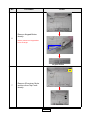
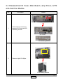
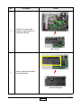
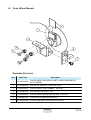
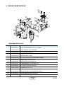
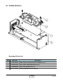
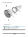
1
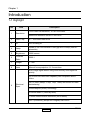
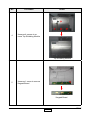
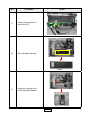
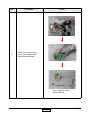
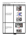
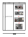
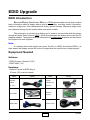
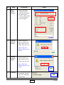
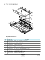
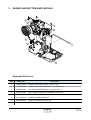
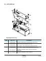
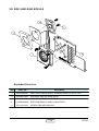
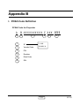
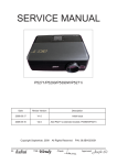
SERVICE MANUAL
Model Name : EP747
Prepared by SI :
________________________________________
Prepared by TSE :
________________________________________
Checked by :
________________________________________
Approved by :
________________________________________
Date
Revise Version
2005/12/13
V1.0
Description
Initial Issue
Copyright December, 2005 . All Rights Reserved
Preface
This manual is applied to EP747 0.7” DMD XGA digital projection system. It’s the mode of single Panel,
180 Watt Compact P-VIP Lamp and 1024(H) x 768(V) resolution. The manual gives you a brief description of basic technical information to help in service and maintaining the product.
Your customers will appreciate the quick response time when you immediately identify problems that occur
with our products. We expect your customers will appreciate the service that you offer them.
This manual is for technicians and people who have an electronic background. Send the product back to
the distributor for repairing and do not attempt to do anything that is complex or is not mentioned in the
troubleshooting.
NOTICE :
The information found in this manual is subject to change without prior notice. Any subsequent changes
made to the data herein will be incorporated in further edition.
Copyright 2005, December
All Rights Reserved
Manual Version 1.0
i
EP747
Table of Contents
Chapter 1
Chapter 2
Chapter 3
Chapter 4
Chapter 5
Introduction
1-1
Highlight
Mechanical Specification
Optical Specification
Environment
Compatible Mode
1-1
1-2
1-2
1-3
1-5
Disassembly of Procedure
2-1
Equipment Needed
Disassemble Lamp, Top Cover, Keypad Board and IR Receiver
Disassemble I/O Cover, Main Board, Lamp Driver, LVPS and
Axial Fan Module
Disassemble Engine Module, DMD Chip, DMD Board, Color Wheel
and Photo Sensor Board
Disassemble Focus Ring, DMD Fan, Speaker, Blower Fan and
Elevator Module
2-1
2-2
Troubleshooting
3-1
Equipment Needed
Main Procedure
3-1
3-1
Function Test and Alignment Procedure
4-1
Test Equipment Needed
Service Mode
Test Condition
Inspection Procedure
4-1
4-1
4-2
4-2
Firmware Upgrade Procedure
5-1
Equipment Needed
Installation Procedure
Firmware Upgrade Procedure
5-1
5-1
5-6
2-6
2-11
2-14
EP747
Chapter 6
EDID Key-in Procedure
6-1
Equipment Needed
Setup Procedure
DDC Key-in Procedure
6-1
6-2
6-2
Appendix A
7-1
Exploded Overview
7-1
Appendix B
7-17
PCBA Code Definition
7-17
Appendix C
7-18
Serial Number System Definition
Reader’s Response
7-18
7-19
ii
EP747
Chapter 1
Introduction
1-1 Highlight
No
Item
Description
True 1024x768 resolution, 16.7M True colors
1
Resolution
2
DMD Chip
0.7’’ XGA DDR DMD XGA
3
ID
H72 Housing ID
4
Lamp
Osram P-VIP 180-230Watt 1.0arc gap E20.5 Lamp (user replaceable)
5
Brightness
3000 lumens
6
Contrast
Ratio
2000:1
7
Weight
7.1 lbs.
8
Lens
Manual focus projection 1:1.2 zoom lens
Maximum resolution SXGA+ 1400*1050
Auto image signal detect using most recently used signal as
priority
NTSC/PAL/SECAM video capability with composite and SVideo
9
Electrical
Spec
HDTV video (480i/p, 576i/p, 720p, 1080i) with 480i/576i/1080i
deinterlacing
Photocatalysis (O2air) Technology
VGA with Audio 1 (could by fixed)
1 audio outRS232/mini connector (not D-Sub9)
DVI-I (connector) (accept DVI-Dsignal) with HDCP
1-1
EP747
No
Item
Description
Wireless remote with mouse and laser pointer
8
Electrical
Spec
9
Compatibility
SXGA+/SXGA/XGA/SVGA/VGA/MAC
10
Speaker
one 3 Watt speaker
11
Audio
4 audio in and 1 audio out
Dual VGA (d-sub 15) (support SCART/RGB/YPbPr)
1-2 Mechanical Specification
No
Item
Description
1
Weight
Approximate 7 lbs
2
Projector
control keypad
Power/standby, Directional keys, enter, source, menu
Power indicator lights
“Lamp” Red:blinking red for fan locked
“Temp” Red
“Power” Green:blinking green (warming up)
orange (cooling up)
4
Cooling System
- Advanced air flow
- Fans with low system acoustic noise level
- Temperature control circuits with adaptive voltage control fan
speed
- High Altitude fan setting for user setting
5
Tilt Angle
7 degrees with elevator mechanism
3
1-3 Optical Specification
No
Item
Description
1
DMD
Single 0.7” 12D DDR DMD XGA
2
Resolution
Native 4:3, 1024*768 resolution
3
Brightness
2040 lumens (Minimum)
2550 lumens (Typical)
1-2
EP747
No
Item
Description
4
Contrast
1200:1 (Minimum)
1500:1 (Typical)
5
Uniformity
65% (Minimum)
75% (Typical)
6
Displayable
colors
16.7 million colors 256 shades of gray
7
Color temperature:
7500ºK (Low, Mid, High selectable)
adjustable to 6500ºK - 9500ºK
8
Projectors
lens
1.2x zoom lens,
2.0 – 2.4 throw ratio
With ability to attach long throw and short throw lens
9
screen size
Adjustable from 30.75” to 300”.(Diagonal)
10
Projection
distance
1.5 – 12.2meter
11
Keystone
+/- 16% Vertical only (DDP2000)
1-4 Environment
No
Item
Description
1
Temperature
- Operating: 5 -- 35°C
- Storage: -20 -- 60°C
2
Maximum
Humidity
- Operating: 5 -- 35°C, 80% non-condensing
- Storage: -20 -- 60°C, 80% non-condensing
3
Acoustic
noise level
- 37dB (A)( Typical, 23 ± 2ºC) with wind tunnel design
37 dB(A) 230W Normal mode.
32 dB(A) 180 W ECO-mode.
Follow ISO-7779 regulation sound pressure level A
weighting measurement
4
Lamp life
-2000 hours typical, 50% survival rate (Full power Mode)
-4000 hours min, 50% survival rate (Eco Mode)
1-3
EP747
No
Item
Description
5
Altitude
- Operating 0~2,500 ft 5°C~35°C
2,500~5,000 ft 5°C~30°C
5,000~10,000 ft 5°C~25°C
- Storage 40,000 ft (Max)
6
MTBF
12000 HRs
1-4
EP747
1-5 Compatible Mode
Analog
Compatibility
Resolution
V-Sync [Hz]
H-Sync [KHz]
VGA
640x350
70
31.5
640x350
85
37.9
640x400
85
37.9
640x480
60
31.5
640x480
72
37.9
640x480
75
37.5
640x480
85
43.3
720x400
70
31.5
720x400
85
37.9
800x600
56
35.2
800x600
60
37.9
800x600
72
48.1
800x600
75
46.9
800x600
85
53.7
1024x768
60
48.4
1024x768
70
56.5
1024x768
75
60.0
1024x768
85
68.7
1280x1024
60
63.98
1280x1024
75
79.98
SXGA+
1400x1050
60
63.98
MAC LC 13”
640x480
66.66
34.98
MAC II 13”
640x480
66.68
35
MAC 16”
832x624
74.55
49.725
MAC 19”
1024x768
75
60.24
MAC
1152x870
75.06
68.68
MAC G4
640x480
60
31.35
I Mac DV
1024x768
75
60
I Mac DV
1152x870
75
68.49
I Mac DV
1280x960
75
75
SVGA
XGA
SXGA
1-5
EP747
Digital
Mode
Resolution
V-Sync [Hz]
H-Sync [KHz]
VGA
640x350
70
31.5
640x350
85
37.9
640x400
85
37.9
640x480
60
31.5
640x480
72
37.9
640x480
75
37.5
640x480
85
43.3
720x400
70
31.5
720x400
85
37.9
800x600
56
35.2
800x600
60
37.9
800x600
72
48.1
800x600
75
46.9
800x600
85
53.7
1024x768
60
48.4
1024x768
70
56.5
1024x768
75
60.0
1024x768
85
68.7
SXGA
1280x1024
60
63.98
SXGA+
1400x1050
60
63.98
SVGA
XGA
1-6
EP747
Chapter 2
Disassembly Process
2-1 Equipment Needed
Item
Photo
Item
Screw Bit
(+) :107
Hex Sleeves
5mm
Hex
Sleeves
8mm
Tweezers
2-1
Photo
EP747
2-2 Disassemble Lamp, Top Cover, Keypad Board and IR
Receiver
No
Procedure
1
Unscrew 1 screw to remove
Lamp Cover
2
Unscrew 2 screws to remove Lamp Module
Photo
Lamp
2-2
EP747
No
3
Procedure
Photo
Unscrew 5 screws and
unplug FPC Wire to remove
Top Cover
Top Cover
FPC Wire
2-3
EP747
No
Procedure
4
Unscrew 4 screws to remove Top Shielding Module
Photo
Top Shielding Module
5
Unscrew 1 screw to remove
Keypad Board
Keypad Board
2-4
EP747
No
6
Procedure
Photo
Remove Keypad Button
directly.
Notice: please turn Keypad Button at 45 angle
45 angle
Keypad Button
7
Remove IR receiver, Mylar
and lens from Top Cover
directly.
IR Receiver
2-5
EP747
2-3 Disassemble I/O Cover, Main Board, Lamp Driver, LVPS
and Axial Fan Module
No
1
Procedure
Photo
Unscrew 8 hex screws to
remove I/O Cover and I/O
Shielding Moudle.
I/O Cover
I/O Shileding Module
2
Remove Light Cut Mylar.
I/O Shileding Module
2-6
EP747
No
3
Procedure
Photo
Unscrew 3 screws to remove Air Duct Module.
Air Duct Module
4
Remove Isolator Mylar
directly.
Isolator Mylar
2-7
EP747
No
5
Procedure
Photo
Unscrew 5 screws and
unplug 9 connectors to remove Main Board
Main Board
6
Remove Main Board Mylar
from Main Board.
Main Board Mylar
2-8
EP747
No
Procedure
7
Unscrew 5 screws and
unplug 3 connectors to
remove Lamp Driver, Lamp
Driver Holder and Lamp
Driver Mylar.
Photo
Lamp Driver
8
Lamp Driver Lamp Driver
Maylar
Holder
Unscrew 5 screws to remove LVPS Shielding
Module.
LVPS Shielding Module
2-9
EP747
No
Procedure
9
Unplug 3 connectors to
remove LVPS.
10
Take off Maylar directly.
Photo
Mylar
11
Unscrew 2 screws to remove Axial Fan Module.
Axial Fan module
2-10
EP747
2-4 Disassemble Engine Module, DMD Chip, DMD Board,
Color Wheel and Photo Sensor Board.
No
1
Procedure
Photo
Unscrew 2 screws to remove Wire 2P#22 220C.
Wire 2P#22 220C
2
Unscrew 1 screw to remove
Blower Duct.
Blower Duct
2-11
EP747
No
3
Procedure
Photo
Unscrew 6 screws to remove Engine Module and
Upper Lens Supporter.
Engine Module
4
Upper Lens Supporter
Unscrew 4 screws to remove Heatsink and 2
Springs.
Heatsink & 2 Springs
5
Unscrew 4 hex screws to
remove DMD Board and
DMD Chip.
DMD Board & DMD Chip
2-12
EP747
No
6
Procedure
Photo
Unscrew 2 screws to remove Color Wheel and
Photo Sensor Board.
Color Wheel & Photo
Sensor Board
2-13
EP747
2-5 Disassemble Focus Ring, DMD Fan, Speaker, Blower Fan
and Elevator Module
No
1
Procedure
Photo
Unscrew 3 screws and use
a tweezers to loose 3 tenons to separate Replace
Ring from Focus Ring.
Replace Ring &
Focus Ring
2
Unscrew 2 screws to remove DMD Fan and Speaker modulen from Buttom
Module.
DMD Fan & Speaker
2-14
EP747
No
Procedure
3
Unscrew 4 screws to break
down DMD Fan and Speaker.
Photo
2-15
EP747
No
4
Procedure
Photo
Unscrew 3 screws to remove Power Shielding
Module.
Power Shielding Module
5
Unscrew 3 screws to remove Blower Fan.
Blower Fan
6
Unscrew 2 screws to remove Interrupt Switch
Module.
Interrupt Switch
Module
2-16
EP747
No
7
Procedure
Photo
Unscrew 3 screws to remove Bottom Base and
Down Less Supporter.
Bottom Base & Down Less Supporter
8
Take off Elevator Foot directly.
Elevator Foot
2-17
EP747
No
Procedure
9
Unscrew 2 screws to remove Front Shielding Module.
Photo
Front Shielding Module
10
Turn Bottom Cover to the
obverse side and use a
tweezers to loose the tenon
to remove Elevator Module.
Elevator Module
2-18
EP747
Chapter 3
Troubleshooting
3-1 Equipment Needed
- PC or Pattern Generator
- DVD Player (Video, S-Video, Audio)
- Quantum Data 802B or CHROMA 2327
3-2 Main Procedure
No
Symptom
Procedure
1
No Power
- Ensure the Power Cord and AC Power Outlet are securely
connected
- Check Lamp Cover and Interrupt Switch
- Ensure all connectors are securely connected and aren’t
broken
- Check DC-DC
- Check Ballast
- Check Main Board
2
Auto Shut
Down
- Check LED Status
a. Lamp LED Light
- Check Lamp
- Check Lamp Driver
- Check Main Board
b. Temp LED Light
- Check Thermal Sensor
- Check Thermal Switch
- Check Fan
c. Color Wheel
- Check Color Wheel
- Check Photo Sensor
3
No Image
- Ensure the Signal Cable and Source work
(If you connect multiple sources at the same time, use the
“Source” button on the control panel to swtich)
- Ensure all connectors are securely connected and aren’t
broken
- Check Main Board
- Check DMD Board
- Check Color Wheel
- Check DMD Chip
- Check Engine Module
3-1
EP747
No
Symptom
Procedure
4
No Light On
- Ensure all connectors are securely connected and
aren’t broken
- Check Lamp Module
- Check DC-DC
- Check Ballast
- Check Main Board
5
Mechanical Noise
- Check Color Wheel
- Check Fan Module
6
Line Bar / Line
Defect
- Check if the DMD Chip and the DMD Board are
assembled properly
- Check DMD Board
- Check DMD Chip
- Check Main Board
7
Image Flicker
- Do “Reset” of the OSD Menu
- Ensure the Signal Cable and Source work
- Check Lamp Module
- Check Color Wheel
- Check DMD Board
- Check Main Board
8
Color Abnormal
- Do “Reset” of the OSD Menu
- Adjust Color Wheel Index
- Check Main Board
- Check DMD Board
- Check Color Wheel
9
Poor Uniformity /
Shadow
- Ensure the Projection Screen without dirt
- Ensure the Projection Lens is clean
- Ensure the Brightness is within spec.
(Replace the Lamp if the Brightness is less
than spec.)
- Check Engine Module
10
Dead Pixel / Dust
(Out of spec.)
- Ensure the Projection Screen without dirt
- Ensure the Projection Lens is clean
- Clean DMD Chip and Engine Module
- Check DMD Chip
- Check Engine Module
11
Garbage Image
- Ensure the Signal Cable and Source work
- Check Main Board
- Check DMD Board
3-2
EP747
No
Symptom
Procedure
12
Remote Controll
or Control Panel
Failed
- Remote Control
a. Check Battery
b. Check Remote Control
c. IR Receiver
- Control Panel
a. Check FPC
b. Check Keypad
c. Check Main Board
13
Function Abnormal
- Do “Reset” of the OSD Menu
- Check Main Board
- Check DMD Board
3-3
EP747
Chapter 4
Function Test & Alignment Procedure
4-1 Test Equipment Needed
- IBM PC with XGA resolution (Color Video Signal & Pattern Generator)
- DVD player with Multi-system (NTSC/PAL/SECAM), equipped “Component”, “S-Video”
and “Composite”
- HDTV Tuner or Source (480P, 720P, 1080i)
- Minolta CL-100
- Quantum Data 802B or CHROMA2327
- After changing parts, check the information below.
Charge
Parts/
Update
Version
Update
Color
Wheel
Index
PC
Calibration
YPbPr
Calibration
M/B
v
v
v
v
FW
v
Color
Wheel
Reset
Lamp
Use
Time
Factory
Reset
EDID
v
v
v
v
Lamp
Module
v
4-2 Service Mode
No
Item
Step
1
Service
Mode
1. Turn on the projector and input the signal.
2. Press and hold “Select“ and “Menu“ simultaneously.
3. “Service Mode Menu” will be shown after pressing “Menu” and
“Select” for 3 seconds.
4. After confirming the configuration, press “Menu” and exit.
2
Factory
Reset
After final QC step, we have to erase all saved change again and
restore the factory defaults. The following actions will allow you to
erase all end-users’ settings and restore the original setting:
1. Please enter Menu.
2. Use OSD to reset.
4-1
EP747
4-3 Test Condition
- Circumstance Brightness : Dark room less than 0.5 lux.
- Inspection Distance : 1.5m~3m for functional inspection
- Screen Size : 60 inches diagonal (wide)
- After repairing each EP747, the unit should be burn-in (Refer to the table below).
Symptom
Burn-in Time
Normal Repair
2 Hours
NFF
4 Hours
Auto Shutdown
6 Hours
4-4 Inspection Procedure
No
Step
Specification
Procedure
Frequency
and Tracking
Eliminate visual
wavy noise by
Rsync, Frequency or Tracking
selection.
- Test Signal :
1024x768@60Hz
- Test Pattern : General-1
- check and see if image
sharpness and focus
are well-performed.
- If not, re-adjust by the
following steps:
(1) Select “Frequency”
function to adjust
the total pixel number
of pixel clock in one
line period.
(2) Then, select
“Tracking” function
and use right or left
arrow key to adjust
the vgalue to
minimize video flicker.
Boundary
Horz. And Vert.
position of
video should be
adjustable to
be the screen
frame.
- Test Signal :
1024x768@60Hz
- Test Pattern : General
- Adjust Resync or
Frequency / Tracking /
H. Position / V. Position
to the inner of the screen.
1
2
4-2
Photo
EP747
No
3
Step
Focus
Specification
The text in the
corner should
be clear after
adjust the focus
ring.
Procedure
Photo
- Test Signal :
1024x768@60Hz
- Test Pattern : Ful-xga
- Adjust the center
clearly; meanwhile,
one slightly vague
corner in the image is
allowed.
- Test Signal : 720p,
1080i
- Test Pattern : Master
- Equipment: Quantum
Data 802B or
CHROMA2327
4
5
HDTV
Color
Performance
No discolor
*Please refer to
page 4~7 to enter
Service Mode. Use
720P&1080i signal,
Master pattern to do
HDTV test. Color cannot discolor to purple
and blue. If the line
disclors, it’s normal.
If the test result was in
discoloration or flickering, please return the
unit back to the repair
center.
- Test Signal :
1024x768@60Hz
- Test Pattern : PANAICON Pattern & 64
GRAYS RGBW
- Please check and
ensure if each color is
normal and distinguishable.
- If not, please adjust
color index of the
Engineering Mode.
- Fix OSD to re-sync or
track Frenquency.
4-3
EP747
No
Step
Specification
Procedure
Screen
Uniformity
Should be
compliant with
60%.(Minimum)
- Test Signal :
1024x768@60Hz
- Test Pattern : Full White
Pattern & Full Black
Pattern
- Please check and ensure
the unit is under the spec.
- Please check and see if
it’s in normal conidtion.
- If not, please return the
unit to repair area.
6
7
Light Leak
The unit can’t
accept the leakage is brighter
than Gray 10
pattern
Photo
- Test Signal :
1024x768@60Hz
- Test Pattern : Gray 10
Pattern
- Please check and see if
the light leaks *Note
- The unit cannot accept
the leakage is brighter
than Gray 10 Pattern
Note:
Light leak on reflective
edge, eyecatcher, bond
wires and exposed metal.
4-4
EP747
No
Step
Specification
Procedure
Photo
- Once Main Board is
changed, firmware upgrade,
YPbPr Calibration & PC
Calibration should be done
as well.
8
9
Calibration
R, G,
B and
White
Color
Performance
Calibration Pattern should be
in full screen
mode
Each R, G, B
color should be
normal without
color abnormal
issue.
- YPbPr Calibration
- Test Signal : 480P
- Test Pattern : TV BAR
- PC Calibration
- Test Signal :
1024x768@60Hz
- Test Pattern : White (up)
Black (down)
Note:
1. Calibration Pattern should
be in Full Screen Mode.
2. Please refer to 4-2.
Guide to Entering Service
Mode and Facotry Reset
for entering Service Mode.
3. Choose and access
YPbPr Calibration & PC
Calibration for correction
in Service Mode. Choose
“Menu” to leave the Service
Mode after all.
- Test Pattern : R,
G, B and White
Color
4-5
EP747
No
Specification
Procedure
Dead Pixel
(Bright pixel)
Cannot accept any
bright pixel
- Test Pattern : Full
Black
Dead Pixel
(Dark pixel)
The numbers of
dead pixel should
be smaller or
amount to 6 pixel.
- Test Pattern : Full
White
11
Blemish
(Bright)
The bright blemish
cannot be accepted if the problem
appear with Gary
30 pattern
- Test Pattern :
Gray 30
12
Blemish
(Dark)
The dark blemish
cannot be accepted if the problem
appear with Blue
60 pattern.
- Test Pattern :
Blue 60
10
Step
4-6
Photo
EP747
Firmware Upgrade
Equipment Needed
Software : (DDP 2000- USB)
- DLP Composer
- Firmware (EP747)
Hardware :
Item
Photo
Item
Projector
(EP747)
USB Cable
Power Cord
PC or Laptop
5-1
Photo
EP747
Installation Procedure
DLP Composer Lite Setup Procedure
No
Step
Procedure
1
Execute
FW program
Choose
“DLP Composer Lite
v3.6 Setup” program.
2
Next
Click “Next” button.
3
Next
1. Reading the “License
Agreement” rules.
2. Choose “I accept and
agree to be bound by
all the terms and
conditions of this
License Agreement”
icon.
3. Click “Next” button.
4
Next
Click “Next” button.
Photo
5-2
EP747
No
Step
Procedure
5
Next
1. Choose “All” icon.
2. Click “Next” button.
6
Next
Click “Next” button.
7
Processing
The program is executing “Initializing” status.
Photo
5-3
EP747
USB Driver Upgrade Procedure
No
1
Step
Set-up
Procedure
Photo
1. Hold on “Enter” button
and plug in Power
Cord while holding on
“Enter”.
2. Wait for about 5 secs.
3. Once Power, Lamp,
Temp LED lights up,
plug in USB Cable
into the Projector &
PC
(Note: The system fan
will not function. The
light will not function as
well.)
2
Execute
Program
Execute the C:\Program
files\DLP Composer\usbupdata.cmd
(Note: The “DLP Composer” program must be
closed first.)
3
Type any
key to
continue
Press any key to continue. Then, wait for about
1 minute.
5-4
EP747
No
Step
Procedure
4
Update
Successfully
Click “OK”. The USB
driver is updated successfully.
5
Device
Manager
1. Right click “My
computer” on the
desktop.
2. Select “Properties”
on the popup menu
to launch the “System
Properties” window.
3. Choose “Hardware”
and then click “Device
Manager”.
6
Ensure
“DDP2000”
& “WinDriver” are
properly
installed
Click “Jungo” to ensure
“DDP2000” and “Windriver” are properly
installed. If not, repeart
Step 1~5.
Photo
Device Manager
5-5
EP747
Firmware Upgrade Procedure
No
1
Step
Set-up
Procedure
Photo
1. Hold on “Enter” button and
plug in Power Cord while
holding on “Enter”.
2. Wait for about 5 secs.
3. Once Power, Lamp, Temp
LED lights up, plug in USB
Cable into the Projector and
link to PC USB.
(Note: The system fan will not
function. The light will not
function as well.)
2
Execute the “DLP ComposeTM” file..
3
Click “Edit” and “Preferences”.
1
2
4
1. Click “Library”.
2. The library path
located in the default
installation directory
is C:\Program Files\
DLP Composer.
If not, press “Browse” to
select the right path.
5
1. Select “Edit\Prefer
ences\Communi
cations” and choose
“USB”.
2. Click “OK”.
1
USB
Vendor: 0x451
Product: 0x2000
2
OK
5-6
EP747
No
6
Step
Procedure
1. Choose “Flash
Loader”
2. Click “Browse” to
search the firmware
file. (EP747)
3. Select the item “Skip
Boot Loader Area
(load all but the first
16KB).”
4. Click “Reset Bus” to
erase the flash
memory.
(Note: If the error message “cannot open USB
driver - No projectors
found” appears, please
replug the USB Cable
and check driver again
and then re-do the
above procedures.
7
Photo
1
2
3
4
Note:
1. If the firmware is
ready, click “Start
Download” to process
the firmware upgrade.
2. Click “Yes” to erase
the flash memory.
2
1
5-7
EP747
No
Step
8
Proceeding
9
10
Procedure
Photo
Proceeding Picture
1. When Firmware
Upgrade Process is
finished, the LED
power light on.
2. Unplug USB Cable
and Power Cord.
Re-plug in Power
Cable.
Check
Firmware
Restart the unit and
enter the Service Mode
to check the Firmware
Version.
(For entering Service
Mode, please refer to
Chapter 4 Function Test
and Alignment Procedure.)
5-8
EP747
EDID Upgrade
EDID Introduction
Extended Display Identification Data is a VESA standard data format that contains
basic information about a display device and its capabilities, including vendor information,
maximum image size, color characteristics, factory pre-set timings, frequency range limits,
and character strings for the monitor name and serial number.
The information is stored in the display and is used to communicate with the system
through a Display Data Channel (DDC), which sites between the display device and the PC
graphics adapter. The system uses this information for configuration purposes, so the monitor
and system can work together.
Note:
If a display device has digital input ports, like DVI or HDMI, but without EDID in its
main board, the display device will show no image while the input source is digital signal.
Equipment Needed
Software:
- EDID Program (Generic V0.51)
- EDID Table (*.ini)
Hardware:
- Generic Fixture for EDID Key-in
(Fixture: JP3 must be closed)
Item
Photo
Item
RS-232
Cable
(F - M)
Power
Adapter for
Fixture
DVI Cable
Generic
Fixture
VGA Cable
Power Cord
6-1
Photo
EP747
Item
Photo
Item
Photo
One additional
monitor (for
PC
checking the program execution)
Projector
(EP747)
Setup Procedure
No
Step
Procedure
Photo
1
Connect
All Ports
1. Power Adapter to Fixture JP1
2. Fixture P1 to PC COM1 Port
3. Fixture P2 to Projector Analog Port
4. Fixture P3 to Projector Digital Port
Adapter
JP1
P1
RS-232 Cable
2
Power On
Fixture
To Digital Port
P3
P2
To Analog Port
Power on Fixture
EDID Key-In Procedure
No
Step
Procedure
1
Execute
EDID
Program.
Click on “EDID” to execute EDID Program.
2
Choose
Model
1. In the Port Selection
Bar, please choose
the Port that you use.
Ex: If you use “COM
1”, choose COM 1 in
the Port selection.
2. Click on “Model”.
3. Choose the EDID that
responses to the
model that you
choose.
Photo
1
2
6-2
3
EP747
No
3
Step
Key in
Serial
Number
Procedure
Photo
1. Key in the Serial
Number into the
Barcode blank space.
2. In “Write Source
Select”, make a check
in “VGA” and “DVI”.
3. Click “Program”.
1
3
2
4
Change
Cable to
Analog
“Please change the
Cable to Analog” message is shown on the
screen, then click “OK”.
(Note: “RUN” message will appear on the
screen.)
5
Change
Cable to
Digital
“Please change the
Cable to Digital” message is shown on the
screen, then click “OK”.
(Note: “RUN” message will appear on the
screen.)
6
Finished
When the EDID program
is completed, the message, “OK”, will appear
on the screen.
6-3
EP747
No
Step
Procedure
7
Check
the whole
process
1. In the “Read Item”
Selections, choose
the Port that you use.
Ex: If you use the
Analog Port, choose
“Analog” in the “Read
Item”.
2. Click on “Read” to
read EDID
information.
3. The “EDID
Informations” will
show the result.
Photo
3
2
4
1
(Note: After pressing “Read”, if the code
in the Serial Blank is
scrambled, please make
a check in “Trans”.)
4. Click “Reset” to do the
next unit or “Exit” to
close the EDID
program.
Note
PS.
Both Analog and Digital are needed to be
checked.
6-4
EP747
Appendix A
Exploded Overview
I.
EP747 UNIT
7-1
EP747
Exploded Parts List
Item
PART_NO
Description
1
51.83F11G011
LAMP COVER PC+ABS EP747
2
51.83F30G001
DMD HEATSINK MYLAR FOR THERMAL GS 0.43t HD72
3
51.83R03G001
WT41 ZOOM RING PC EP747
4
51.83R06G001
BLOWER DUCT PC EP747
5
61.00018G002
LOCK SCREW PAN MECH M3*8.5-3.5 BLACK
6
70.83F04G001
ASSY LAMP MODULE HD72
7
70.83F20G001
ASSY AXIAL FAN MODULE HD72
8
70.83R01G001
ASSY TOP COVER MODULE EP747
9
70.83R02G001
ASSY BOTTOM COVER MODULE EP747
10
70.83R05G001
ASSY PCB MAIN BD MODULE EP747
11
70.83R06G001
ASSY POWER MODULE EP747
12
70.83R10G001
ASSY ENGINE & BOTTOM BASE MODULE EP747
13
70.83R20G001
ASSY SIDE SHIELDING MODULE EP747
14
75.83F01G001
BUY ASSY AIRDUCT MODULE HD72
15
85.005AG.408
SCREW HEX I/O #4-40 H4xL8 Ni NYLOK
16
85.1F123.060
SCREW PAN MECH W/SF M3x6 Ni
17
85.3A122.040
SCREW CAP MECH M2*4 Ni
18
85.WA123.080
.SCREW PAN TAP M3*8 Ni
7-2
EP747
II.
SUB ENGINE MODULE
7-3
EP747
Exploded Parts List
Item
PART_NO
Description
1
23.80J20G001
CONDENSER LENS2
2
23.80J20G011
CONDENSER LENS 3
3
23.83J06G001
GLASS RELAY LENS
4
52.81R03G001
LENS ANTIDUST 739 SILICONE RUBBER
5
52.81R12G001
RELAY ANTIDUST YM08 739 SILICONE RUBBER
6
52.81R18G001
PORON ENGINE TO DUCT DV10
7
61.80J05G002
ROD SPRING 739 SUS301 0.25t
8
61.83J09G001
ROD COVER SUS301 0.5t PD527
9
70.83R13G001
ASSY OPTICAL LENS MODULE EP747
10
70.83R14G001
ASSY COLOR WHEEL MODULE EP747
11
70.83R15G001
ASSY ROD MODULE EP747
12
70.83R16G001
PRE ASSY ENGINE BASE MODULE EP747
13
70.83R17G001
PRE ASSY ENGINE BASE MODULE EP747
14
75.80W15.002
BUY ASSY ZOOM RING STOP EMI MODULE 2300MP
15
85.1A326.060
SCREW PAN HEAD MECH M2.6x6 BLACK
16
85.1A526.060
SCREW PAN MECH M2.6x6 Ni NYLOK
17
85.1A626G040
SCREW PAN MECH M2.6x4 BLACK NYLOK
18
85.1F126G060
SCREW PAN MECH W/SF M2.6x6 Ni
7-4
EP747
III. ENGINE MODULE
Exploded Parts List
Item
PART_NO
Description
1
11.009F0G005
CNNT F 166P FOR 0.55" SVGA LGA DMD SOCKET;FOXCONN
2
41.81R17G001
EMI GASKET TAPE 0.13t FOR ENGINE DV10
3
41.83F05G001
GASKET h%%204%%160/(L*45,W*7,H*10)
4
48.858DMGD14
DMD 1024*768 PIXEL DDR FTP 0.7" XGA
5
51.80B31G002
DMD INSULATOR MYLAR 0.435t T90
6
51.80W33G001
ENGINE BOTTOM MIRROR1 TAPE 3M-J350 2300MP "GREEN"
7
51.80W44G001
8*10*0.5t MYLAR FOR 2300MP
8
52.80J01G001
DMD ANTIDUST RUBBER 739 SILICONE RUBBER
9
52.87130G001
RUBBER BLOWER 595925
10
52.87319G001
DMD THERMAL PAD 18*13*0.5t
11
61.80J10G001
DMD LIGHT MASK 739 SUS301
12
61.80J48G002
DMD HEATSINK BACKER PLATE A6061 739
13
61.88605G001
DMD HEATSINK A1070 Ivy10X
14
61.88608G001
DMD HEATSINK SPRING PLATE SUS301 0.4t Ivy10X
15
61.88611G001
DMD SCREW Ivy10X
16
70.83R12G001
ASSY SUB ENGINE MODULE EP747
17
80.83R02G001
PCBA DMD BD FOR EP747
18
85.1A523G040
SCREW PAN MECH M3*4 NYLOK
7-5
EP747
IV. TOP COVER MODULE
Exploded Parts List
Item
PART_NO
Description
1
42.83F04G001
CABLE FFC 14P PITCH=1.0mm HD72
2
51.83F01G011
TOP COVER PC+ABS EP747
3
51.83F07G011
KEYPAD BUTTOM PC EP747
4
51.83F08G011
IR FRONT LENS EP747
5
51.83F26G001
FRONT IR MYLAR 0.2t HD72
6
51.83F29G001
KEYPAD LED LENS HOLDER PC HD72
7
75.83F09G001
BUY ASSY TOP SHIELDING MODULE HD72
8
80.83F04G001
PCBA IR SENSOR BD H72
9
80.83R03G001
PCBA KEYPAD BOARD EP747
10
85.1A123.040
SCREW PAN MECH M3x4 Ni
7-6
EP747
V.
ENGINE AND BOTTOM BASE MODULE
Exploded Parts List
Item
PART_NO
Description
1
41.83F04G001
GASKET h%%204%%160/(L*125,W*7,H*2)
2
61.83R05G001
DOWN LENS SUPPORTER SECC t=0.8mm EP747
3
61.83R06G001
UP LENS SUPPORTER SECC t=0.6mm EP747
4
70.82G11G001
ASSY LAMP CHANGE PLATE MODULE EP7190
5
70.83F18G001
ASSY BOTTOM BASE MODULE H72
6
85.1A123G050
SCREW PAN MECH M3x5 Ni
7
85.1A126.050
SCREW PAN MECH M2.6*5 (Ni)
8
85.WA123.080
.SCREW PAN TAP M3*8 Ni
7-7
EP747
VI. BOTTOM COVER MODULE
Exploded Parts List
Item
PART_NO
Description
1
51.83F12G011
FRONT LOWER PANEL PC+ABS EP747
2
75.83F05G001
BUY ASSY FRONT SIDE SHIELDING HD72
3
75.83R03G001
BUY ASSY BOTTOM COVER MODULE EP747
4
85.WA123.080
.SCREW PAN TAP M3*8 Ni
7-8
EP747
VII. LVPS MODULE
Exploded Parts List
Item
PART NO
Description
1
51.83R08G001
POWER SHIELDING FORMAX MYLAR EP747
2
70.83R09G001
ASSY SUB LVPS MODULE EP747
3
75.83R05G001
BUY ASSY LVPS SHIELDING MODULE EP747
4
75.83R06G001
BUY ASSY POWER SHIELDING MODULE EP747
5
85.1C224.050
SCREW PAN MECH M4*5 COLOR W/TOOTH
WASHER
6
85.1F123.060
SCREW PAN MECH W/SF M3x6 Ni
7-9
EP747
VIII. SIDE SHIELDING MODULE
Exploded Parts List
Item
PART NO
Description
1
49.83J03G001
MISC 45x10 DMD BLOWER, SUNON B1245PFV1-8A, R TYPE
2
49.83R01G001
SPEAKER 4ohm 3W 90mm EP747
3
52.83R01G001
SIDE SPEAKER SPONGE EP747
4
61.83R04G002
SIDE SHIELDING AL 5052 t=0.8mm EP747
5
85.1A123.060
SCREW PAN MECH M3x6 Ni
7-10
EP747
IV. Color Wheel Module
Exploded Parts List
Item
PART NO
1
23.83J19G001
2
51.80J38G002 MYLAR CW SUPPORT 739 FRPP 0.125t
3
52.83615.001
4
61.80J08G002 CW HOLDER 739 SECC 1.2t
5
61.83628G001 COLOR WHEEL SHOULDER SCREW , EzPro755
6
80.80N04.001
7
Description
COLOR WHEEL R92/G83/W110/B75, SLEEVE BEARING OF
DP739 SERIES
COLOR WHEEL DISC RUBBER , EzPro755
PCBA PHOTO SENSOR BD EP739
85.1A626G040 SCREW PAN MECH M2.6x4 BLACK NYLOK
7-11
EP747
X. ENGINE BASE MODULE
Exploded Parts List
Item
PART_NO
Description
1
23.80J02G011
REFLECTION MIRROR2 OF DP739 SERIAL
2
23.80S10G001
UV/IR FILTER OF DP739 SERIES
3
43.80W01G001
YS11 THERMAL SWITCH
4
51.80W34G001
ENGINE BASE MIRROR2 TAPE 3M-J350 2300MP
5
51.81542G001
TAPE 3M J350 17*15mm
6
52.80J02G002
OFF LIGHT ISOLATOR 739 SILICONE RUBBER
7
61.80J01G001
ENGINE BASE 739 Mg ALLOY
8
61.80J02G001
UVIR HOLDER 739 SUS301 0.3t
9
61.80J07G001
SPRING MIRROR2 739 SUS301 0.25t
10
61.80J39G001
OFF LIGHT PLATE AL VULCAN-1
11
61.83F17G001
BLOWER DUCT AL H72
12
85.1A326.060
SCREW PAN HEAD MECH M2.6x6 BLACK
13
85.1A626G040
SCREW PAN MECH M2.6x4 BLACK NYLOK
14
85.5A126G040
SCREW BINDING MECH M2.6x4 Ni
15
87.FL030G008
WASHER FLAT 7*3.1*0.8t PC PINGOOD WS-1M
7-12
EP747
XI. I/O COVER FAN MODULE
Exploded Parts List
Item
PART NO
Description
1
35.83R01G001 IO LABEL PC 8B35 EP747
2
51.83R02G001 IO COVER EP747
3
75.83R04G001 BUY ASSY IO COVER MODULE EP747
7-13
EP747
XII. POWER MODULE
Exploded Parts List
Item
PART NO
Description
1
51.83R10G001 LAMP DRIVER HOLDER MYLAR FORMAX EP747
2
70.83R07G001 ASSY LAMP DRIVER MODULE EP747
3
70.83R08G001 ASSY LVPS MODULE EP747
4
85.1F123.060
SCREW PAN MECH W/SF M3x6 Ni
7-14
EP747
XIII. SUB LVPS MODULE
Exploded Parts List
Item
PART NO
Description
1
75.80J02G001 ASSY INTERRUPTER SWITCH
2
42.83R01G001 W.A. 16P 170mm LVPS TO M/B EP747
3
4
42.89602.001
W.A. 3P #20 180mm LAMP DRIVER TO LAMP EP759
75.83M01G002 ASSY LITEON LVPS 2400MP
7-15
EP747
XIV. MAIN BOARD MODULE
Exploded Parts List
Item
PART NO
Description
1
51.83F23G001 MB UP INSULATOR MYLAR FRPP 0.43t H72
2
51.83R09G001 MB DOWN INSULATOR MYLAR Frpp 0.43t EP747
3
80.83R01G001 PCBA MAIN BD FOR EP747
7-16
EP747
XV. OPTICAL LENS MODULE
Exploded Parts List
Item
PART NO
Description
1
23.89601G001 YM06 1.2X XGA ZOOM PROJECTION LENS
2
75.83R07G001 BUY ASSY FORCUS RING MODULE EP747
3
85.YA121G040 SCREW FLAT HEAD TAP M1.7*4 Ni
7-17
EP747
XVI. LAMP DIRVER MODULE
Exploded Parts List
Item
PART NO
Description
1
42.80S03G001 W.A. 5P #28 210mm LVPS TO MB TDP-T90
2
51.83F20G001 LAMPDRIVER HOLDER PC+ABS MN3600 HD72
3
75.83J01G001 ASSY OSRAM LAMPDRIVER 230W
4
76.83F01G001 ASSY LAMP DRIVER(OSRAM)) TO LAMP W.A. HD72
5
85.1F123.060
SCREW PAN MECH W/SF M3x6 Ni
7-18
EP747
XVII. ENGINE BASE MODULE
Exploded Parts List
Item
PART NO
Description
1
23.80J02G001 REFLECTION MIRROR1 OF DP739 SERIAL ''
2
51.80J01G001 ENGINE BOTTOM 739 BMC
3
52.80J05G002
4
61.80J06G001 SPRING MIRROR1 739 SUS301 0.25t
PORON RELAY 739 SILICONE RUBBER
7-19
EP747
XVIII. ROD MODULE
Exploded Parts List
Item
PART NO
Description
1
23.83L17G001 INTEGRATION ROD FOR 739 XGA GLASS RELAY SERIES
2
57.81501.001
3
61.83J10G001 ROD HOLDER SUS301 0.2t PD527
UV GLUE 6-628-GEL DYMAX
7-20
EP747
Appendix B
I. PCBA Code Definition
PCBA Code for Projector
A B XXXXXXXXXX C XXX EEEE
1
3
2
1
:
ID
2
:
Vendor Code
3
:
P/N
4
:
Revision
5
:
Date Code
6
:
S/N
4
5
6
C: M/B
B: DMD/ B
7-21
EP747
Appendix C
Serial Number System Definition
Serial Number Format for Projector
A BBB Y WW C D BEMO EEEE
1
2
3
4
5
6
7
1
:
A = Optoma, B~Z = OEM
2
:
Product code (ex: 83R = EP747)
3
:
Y = Last number of the year (ex: 2005 - 5)
4
:
Week of year
5
:
Panel vendor code
6
:
Electrical classification (1=110V, 2=220V, 0=universal)
7
:
B = BIOS version, E = PCB board version,
8
M = Mechanical version, O = Optical version
8
:
Serial code (from 0001~)
EX : A83R529T0AAAA1001
This label “A83R529T0AAAA1001” represents the whole serial number for EP747, including Ver.
1st of BIOS and Ver. 1 of PCB Board. Both mechanical and optical version are 1st. In addition,
panel vendor is TI. It’s produced on 29s-week of 2005 for universal area and its serial code is 1001.
7-22
EP747
*Reader’s Response*
Dear Readers:
Thank you for your backing our service manual up. In order to refine our content of the
service manual and satisfy your requirement. We expect you can offer us some precious
opinions for reference.
Assessment:
A.
What do you think about the content after reading EP747 Service Manual?
Unit
Excellent
Good
Fair
Bad
1. Introduction
2. Disassembly Procedure
3. Troubleshooting
4. Function Test & Alignment Procedure
5. Firmware Upgrade Procedure
6. DDC key-in Procedure
7. Appendix
B.
Are you satisfied with the EP747 service manual?
Item
Excellent
Good
Fair
Bad
1. Service Manual Content
2. Service Manual Layout
3. The form and listing
C.
Do you have any other opinion or suggestion about this service manual?
Reader’s basic data:
Name:
Title:
Company:
Add:
Tel:
Fax:
E-mail:
After your finishing this form, please send it back to Coretronic Customer Service
Dept. by fax: 886-3-563-5333.
7-23
EP747