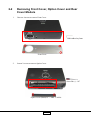
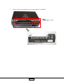
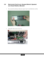
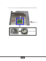
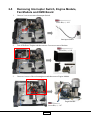
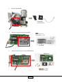
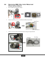
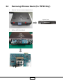
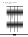
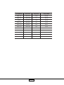
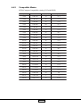
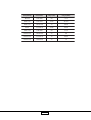
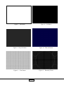
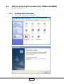
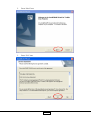
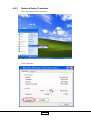
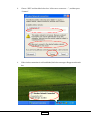
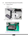
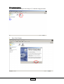
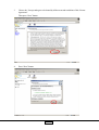
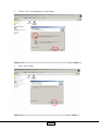
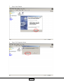
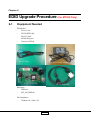
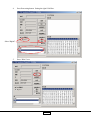
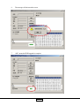
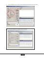
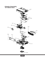
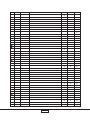
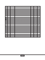
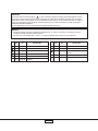
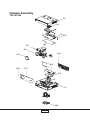
1
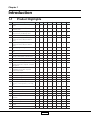
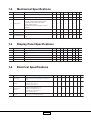
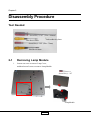
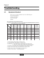
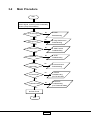
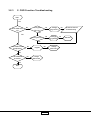
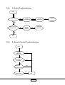
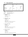
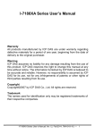
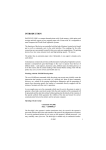
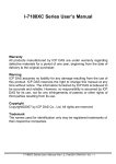
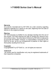
FILE NO. 330-200501 SERVICE MANUAL TDP- T80, TDP-T90, TDP-T91, TDP-TW90 TDP-S80,TDP-S81, TDP-SW80 TDP-MT200 Document Created in Japan Jan., 2005 Preface This manual is applied to T80/T90/T91/TW90/MT200 / S80 / S81 / SW80 DMD Projector with digital imaging functionality based on Digital Micro-mirror Device (DMD) technology. Its the mode of single Panel, 200 watt Lamp. The manual gives you a brief description of basic technical information to help in service and maintaining the product. Your customers will appreciate the quick response time when you immediately identify problems that occur with our products. We expect your customers will appreciate the service that you offer them. This manual is for technicians and people who have an electronic background. Send the product back to the distributor for repairing and do not attempt to do anything that is complex or is not mentioned in the troubleshooting. NOTICE : The information found in this manual is subject to change without prior notice. Any subsequent changes made to the data herein will be incorporated in further edition. Copyright 2005, January All Rights Reserved Manual Version 5.0 Document # 80S-G04-01A Manual Version 1.0 Document # 80S-G04-01A I Table of Contents Chapter 1 Introduction ...................................................................... 1-1 Product Highlights .................................................................................. 1-1 Machanical Specifications ...................................................................... 1-2 Display Panel Specifications ................................................................... 1-2 Electrical Specifications .......................................................................... 1-2 Optical Specifications ............................................................................. 1-3 Environmental Specifications .................................................................. 1-4 Firmware................................................................................................. 1-4 Chapter 2 Disassembly Procedure .................................................. 2-1 Tools Needed .......................................................................................... 2-1 Removing Lamp Module ......................................................................... 2-1 Removing Front Cover, Option Cover and Rear Cover Module .............. 2-2 Removing Top Cover, Keypad Board, Speaker and Select Button Module ...................................................................... 2-4 Removing Main Board, LVPS Module, Lamp Driver Module and Fan Module ...................................................................................... 2-6 Removing Interrupter Switch, Engine Module, Fan Module and DMD Board ...................................................................................... 2-8 Removing DMD Chip, Color Wheel and Photo Sensor Board .............. 2-10 Removing Thermal Board, IR Sensor Board and Fan Duct .................. 2-11 Removing Wireless Board (For TW90 Only) ......................................... 2-12 Chapter 3 Troubleshooting ............................................................... 3-1 Equipment Needed ................................................................................. 3-1 Main Procedure ...................................................................................... 3-2 Main Procedure Description ................................................................... 3-7 Factory Mode ........................................................................................ 3-10 Chapter 4 Function Test and Alignment Procedure ....................... 4-1 Product ................................................................................................... 4-1 Test Equipment ....................................................................................... 4-1 Test Condition ......................................................................................... 4-1 Test Display Modes & Pattern ................................................................. 4-2 Inspection Procedure ............................................................................ 4-10 Wireless Testing Procedure (For TW90 and SW80) ............................. 4-13 Camera Setup Procedure (For T91 and S81) ....................................... 4-25 II Chapter 5 Firmware Upgrade Procedure ........................................ 5-1 Equipment Needed ................................................................................. 5-1 Setup Procedure ..................................................................................... 5-1 Firmware Upgrade Procedure ................................................................ 5-6 Chapter 6 EDID Upgrade Procedure (For MT200 Only) .................. 6-1 Equipment Needed ................................................................................. 6-1 Setup Procedure ..................................................................................... 6-2 EDID Upgrade Procedure ....................................................................... 6-2 Chapter 7 Exploded View and Replacement Parts List .................. 7-1 Packing Assembly (TDP-T80/T90/T91/TW90) ....................................... 7-1 Chassis Assembly (TDP-T80/T90/T91/TW90) ....................................... 7-3 Packing Assembly (TDP-S80/S81/SW80) .............................................. 7-6 Chassis Assembly (TDP-S80/S81/SW80) .............................................. 7-8 Packing Assembly (TDP-MT200).......................................................... 7-11 Chassis Assembly (TDP-MT200) ......................................................... 7-13 III Chapter 1 Introduction 1-1 Product Highlights Ite m 1 De s cription O ne panel 0.7 XGA / 12o DDR DMD projection system T80 T90 T91 TW90 V V V V O ne panel 0.55" WVGA / 12o DDR DMD projection system 2 200 Watt compact P- VIP Lamp (user replaceable, Lamp is driven by 200 Watt lamp driver) V V V High efficiency cooling system with low system acoustic noise level (35 dB(A) in 160W ecomode) S 80 S 81 SW80 V V V V V V V V V V Phoenix X66 200W SHP Lamp (user replaceable) 3 M T200 V V V V V V V High efficiency cooling system with low system acoustic noise level (35 dB(A) in 150W ecomode) 4 Light weight Approx. 2.8K gs. V V V V V V V V 5 Manual focus projection, 1:1.2 mechanical zoom lens V V V V V V V V 6 True 1024 x 768 resolution, 16.7M True colors V V V V V V V True 854 x 480 resolution, 16.7M True colors V True 800 x 600 resolution, 16.7M True colors 7 With up, down, left, and right screen reverse V V V V V V V V 8 Build- in full screen N TSC / PAL / SECAM video capability with S- video / Composite / component through D- sub V V V V V V V V 9 SXGA / XGA / SVGA / VGA / MAC compatibility with two D- Sub 15 pin VGA connector input terminal V V V V V V V V 10 Auto image re- sizing to 1024 x 768 full screen V V V V V V V Auto image re- sizing to 854 x 480 full screen V Auto image re- sizing to 800 x 600 full screen 11 Auto detection of computer signal input V V V V V V V V 12 Auto Image synchronization (Auto- tracking / frequency / position adjustment) by Auto- setting key. V V V V V V V V 13 Freeze function. V V V V V V V V 14 Automatically saves adjustments for future use V V V V V V V V 15 IR remote control function V V V V V V V V 16 Adaptive voltage control fan speed V V V V V V V V 17 Auto & Manual Digital Vertical K eystone Correction V V V V V V V V 18 Built- in one 1W speaker V V V V V V V V Built- in one 2W speaker 19 Camera 20 Wireless V V V 1-1 V 1-2 Mechanical Specifications Ite m Spe cification 1 Dimensions (WxHxD) 2 T80 T90 298x267x100.5 mm (main body) V V V V V V V V Weight Approx. 6.3 lbs. (2.86kg) V V V V V V V V 3 Cooling System - Advanced air flow - Two fans with low system acoustic noise level - Temperature control circuits with adaptive voltage control fan speed - Maximum touch temperature follows UL 60950 regulation V V V V V V V V 4 Tilt Angle 6.8 degree with elevator mechanism V V V V V V V V 5 K eystone correction +/- 16 degree Vertical V V V V V V V V 6 Lamp Door Protection Lamp power supply shut off automatically when door open V V V V V V V V T80 T90 T91 S 81 SW80 V V V V V V V V V 1-3 Ite m 1 De s cription T91 TW90 M T200 S80 S81 SW80 Display Panel Specifications Spe cification Type D e s cription DMD (0.7 12 degree DDR XGA Digital Mirror Device) TW90 M T200 S80 V DMD (0.55" 12 degree DDR WVGA Digital Mirror Device) 2 N umber of active dots 1024(H) x 768 (V) V V V V V 854(H) x 480(V) V 800(H) x 600(V) 1-4 Ite m Electrical Specifications Spe cification De s cription T80 T90 T91 TW90 M T200 S 80 S 81 SW80 1 Power Supply - Input AC 100- 240V~, 3A, 50- 60 Hz with PFC - Variance FAN speed control (Depend on temperature variant) V V V V V V V V 2 Terminals - Computer Input (VGA) - Composite Video Input (x 1) - S- Video Input (Standard x 1) V V V V V V V V 3- 1 Terminals & I/O connector - V V V V V V V V 3- 2 Terminals & I/O connector - Digital Video with HDCP Input (DVI- D) Computer Analog Input (VGA x 1) Component Video Input (RCAx 3) S Video Input (Mini- Din 4- Pin x 1) Composite Video Input (RCA x 1) RS232 (Mini- Din 8pin x 1) V 1-2 Ite m T80 T90 Input signal spec. - Hsync Frequency 15~100 kHz - Vsync Frequency 43~85 Hz - Video Signal RGB (PC) 1.) Analog RGB : 0.7 Vp- p, 75 ohm 2.) Analog RGB : 1Vp- p, 75 ohm 3.) Sync. Signal Separate Sync : (HV) TTL level (bi- polarity) Composite Sync : TTL level (bi- polarity) Sync- on- green : negative sync. 0.3Vp- p - Video 1.) Composite video : 1Vp- p, 75 ohm 2.) S- video Luminance : 0.714Vp- p, 75 ohm 3.) Chrominance : 0.286Vp- p, 75 ohm V V V V V V V V 5 Video Compatibility - Standards : N TSC : M(3.58 MHz), 4.43 MHz PAL : B, D, G, H, I, M, N SECAM : B, D, G, K , K 1, L HDTV : 480i / 576i ; 480p / 576p ; 720p ; 1080i V V V V V V V V 6 XGA / Compression By using DDP2000 Chips to compress SXGA image into XGA display V V V V V V V SVGA / Compression By using "DDP2000" Chips to compress SXGA image into WVGA display 4 Spe cification 1-5 Ite m 1 De s cription T91 TW90 M T200 S80 S81 SW80 V Optical Specifications Spe cification Projection lens D e s cription F#2.4- 2.65 @ 2.4m, f=28.04~35.59mm @ 2.4m. 1.2X Manual Zoom Lens. T80 T90 T91 V V V TW90 M T200 S80 S81 SW80 V V F#2.4- 2.81 @ 2.4m, f=22.34~26.59mm @ 2.4m. 1.2X Manual Zoom Lens. 2 Projection Image Size Adjustable from 24.6" to 246" (Diagonal) V V V V V V V V V V V 3 Throw Distance 1.2m~10m V V V V V V V V 4 Throw Ratio 2 .0 ~ 2 .4 ; 1 0 0 " / 4 .0 6 m ~ 4 .8 8 m V V V V V V V V 5 Brightness 1850(Typical) ; 1600 (Minimum) V V V V V V V V V V 650(Typical) ; 510 (Minimum) 6 Contrast V Full on / off 1600:1 (Typical) 1000 : 1 (Minimum) JBMA 1600 : 1 (Typical) 1000 : 1 (Minimum) V V V V Full on / off 2500:1 (Typical) 1500 : 1 (Minimum) 7 Uniformity JBMA 75% (Typical) 60% (Minimum) V V V V V JBMA 80% (Typical) 65% (Minimum) 8 Lamp V V V V O SRAM E17.5 200W P- VIP Lamp V Phoenix X66 200W SHP Lamp V V V V Philips E19 200W UHP Lamp V 1-3 V V 1-6 Ite m Environmental Specifications Spe cification De s cription T80 T90 T91 TW90 M T200 S80 S81 SW80 1 Temperature O perating : 0~35 C, 80% humidity, non- condensing Storage : - 20~60oC, 80% humidity, non- condensing V V V V V V V V 2 Maximum Humidity O perating : 0~35oC, 80%RH (Max.), non- condensing Storage : - 20~60oC, 80%RH (Max.), non- condensing V V V V V V V V 3 Acoustic noise level 39 dB(A) (in 216W mode, at 23+/- 2oC) 35 dB(A) (in 160W eco mode, at 23 +/- 2oC) while color wheel are running with 7200 rpm V V V V V V V o 38 dB(A) (in 200W mode, at 23+/- 2oC) 35 dB(A) (in 160W eco mode, at 23 +/- 2oC) while color wheel are running with 7200 rpm V 39 dB(A) (in 200W mode, at 23+/- 2oC) 35 dB(A) (in 150W eco mode, at 23 +/- 2oC) while color wheel are running with 7200 rpm 4 Altitude O perating : 0oC~35oC for height : 0~2,500 ft 0oC~30oC for height : 2,500~5,000 ft 0oC~30oC for height : 5,000~10,000 ft fan speed adjusted by O SD menu Storage : 0~40,000 ft 5 MTBF O perating more than 10,000 hours V V V V V V V V 6 Reliability Test 12,000 hours V V V V V V V V 1-7 V V V V V V V V Firmware Ite m D e s cription 1 Firmware A 2 Firmware B 3 Firmware C 4 Firmware D T80 T90 T91 V V TW90 M T200 S 80 S 81 SW80 V V V V V V 1-4 Chapter 2 Disassembly Procedure Tool Needed Screw Bit (+) : 107 (Size : 100mm) Ball-endhex-key 2mm Hex Sleeves 5mm Screw Bit (+) : 102 (Size : 75mm) Hex Sleeves 8mm 2-1 Removing Lamp Module 1. Loosen one screw to remove Lamp Cover, and then loosen 2 screws to remove Lamp Module. Screw Bit (+) : 107 Lamp Module 2-1 2-2 Removing Front Cover, Option Cover and Rear Cover Module 1. Unscrew 4 screws to remove Front Cover. Ball-endhex-key 2mm Front Cover 2. Loosen 2 screws to remove Option Cover. Screw Bit (+) : 107 Option Cover (Blank) PC + ABS - CAOLA 2-2 3. Unscrew 6 hex screws and 2 screws to remove Rear Cover Module. Screw Bit (+) : 102 Rear Cover Module 2-3 2-3 Removing Top Cover, Keypad Board, Speaker and Select Button Module 1. Press A point first and then press B point to separate Top Cover and Main Body carefully. B A 2. Unplug FFC cable to remove Top Cover. 2-4 3. Unscrew 6 screws to remove Keypad Board, Speaker and Select Button Module. Speaker Keypad Board Screw Bit (+) : 107 Select Button Module 2-5 2-4 Removing Main Board, LVPS Module, Lamp Driver Module and Fan Module 1. Unplug all cables from Main Board and Unscrew 5 screws to remove Main Board. Screw Bit (+) : 107 2. Tear off Mylar and then unscrew 5 screws to remove LVPS Module. Screw Bit (+) : 107 Mylar LVPS Module 2-6 3. Unscrew 3 screws to remove Lamp Driver Module. Lamp Driver Module Screw Bit (+) : 107 4. Unscrew 2 screws to remove Fan Module. Screw Bit (+) : 107 Axial Fan Module (70x70x20mm) Note : TW90-Add one cable to link wireless function from Main Board of TW90. (As the picture display) 2-7 2-5 Removing Interrupter Switch, Engine Module, Fan Module and DMD Board 1. Unscrew 2 screws to remove Interrupter Switch. Screw Bit (+) : 102 Interrupter Switch 2. Tear off Deflector Tinplate and then unscrew 5 screws to remove Brackets. Screw Bit (+) : 102 3. Unscrew 6 screws of the red rectangle area and then remove Engine Module. Engine Module Screw Bit (+) : 107 2-8 4. Remove Fan Module. Fan Module (50x50x20mm) 5. Unscrew 4 screws to remove Heat Sink. Screw Bit (+) : 107 Heat Sink 6. Unscrew 4 hex screws to remove DMD Board. DMD Board Hex Sleeves 8mm 2-9 2-6 Removing DMD Chip, Color Wheel and Photo Sensor Board 1. Remove DMD Chip from Engine Module. DMD Chip 2. Unscrew one screw to remove Color Wheel and Photo Sensor Board. Color Wheel Photo Sensor Board 3. Unscrew 3 screws to remove Zoom Ring and Focus Ring from Engine Module. Zoom Ring 2-10 Focus Ring 2-7 Removing Thermal Board, IR Sensor Board and Fan Duct 1. Unscrew one screw to remove Thermal Sensor Board. Screw Bit (+) : 107 Thermal Board 2. Turn over Bottom Cover Module and then unscrew one screw to remove IR Sensor Board. IR Sensor Board Screw Bit (+) : 107 3. Unscrew one screw to remove Fan Duct from Bottom Module. Fan Duct one screw 2-11 Screw Bit (+) : 107 2-8 Removing Wireless Board (For TW90 Only) 1. Unscrew 2 screws to remove Option Cover. Option Cover 2. Pull out the Wireless Board. 2-12 Chapter 3 Troubleshooting 3-1 Equipment Needed T80 / T90 / T91 / TW90 / MT200 / S80 / S81 / SW80 Projector PC (Personal Computer) CD Player, DVD Player VGA to VGA Cable Chroma - After changing parts, check the below information. For example : Change the M/B, then check the Version Update, Color Wheel Delay, RGB Level, Frequency, Phase, Reset Lamp Use Time and Reset All. Update Reset Lamp Use Time Keystone Calibration Reset All (For T90 & S80 Seri es) Version Update Color Wheel Delay RGB Level Frequency Phase M/B V V V V V V V Firmware V V V V V V V DMD Board V V Engine V Change Parts V Lamp Module V LVPS Lamp Driver 1.) Version Update : Refer Chapter 3-4 Hot Key, item 5 2.) Color Wheel Delay : Refer Chapter 3-4 Hot Key, item 7 3.) RGB Level : a. Press “Menu” button on the keypad to enter OSD function. b. Press “UP” or “Down” button to select Image Adjustment Menu. 4.) Frequency : Press “Setup” button, then adjustment from “Frequency” mode. 5.) Phase : Press “Setup” button, then adjustment from “Phase” mode. 6.) Reset Lamp Use Time : Refer Chapter 3-4 Hot Key, item 3 7.) Reset All : Press “Menu” --> Default Setting Menu. 3-1 3-2 Main Procedure Start Connect Power Cord, PC, Video, S-video, & Audio Signal, and then press on/standby button.(Lamp LED will flicker) Is on LED Light On? No A. Power Troubleshooting No B. Image Performance Troubleshooting No C. OSD Function Troubleshooting No D. Audio Troubleshooting No E. Remote Control Troubleshooting No F. Camera Troubleshooting (For T91 and S81) No G. Wireless Troubleshooting (For TW90 and SW80) Yes Is Image OK ? Yes Is OSD function OK ? Yes Is Audio OK ? Yes Is Remote Control OK? Yes Is Camera OK? Yes Is Wireless OK? Yes No Fault Found End 3-2 3-2.1 A. Power Troubleshooting Start Is Power LED indicator ? No Lamp Cover assembly OK ? Yes No Reassemble lamp Cover No Change Main Board No Yes Change Lamp Driver No Change LVPS Is Lamp LED indicator OK ? No Change Lamp Module No Change Main Board No Change DMD Board Yes Is Fan LED indicator OK ? No No No Is Optical Fan working ? Change System Fan Yes Is Temp LED indicator OK ? Yes Is System Fan working ? Change Main Board No Change Optical Fan Change Thermal Board No Is Intake Thermal sensor working ? Yes Yes Is System Fan working ? No Yes Is Lamp lit ? No Change Lamp Module No Yes Is Optical Fan working ? Change System Fan No Change Lamp Driver Yes End 3-3 Change LVPS Yes Change Main Board No Change Optical Fan No Change No Change DMD Board Main Board 3-2.2 B. Image Performance Troubleshooting Start Have image ? No No Cable connections are OK? Change M/B No Change DMD Board No Yes Have garbage pattern ? Yes No Change M/B Change DMD Board No Have bar at the right & left side of image ? Yes Change DMD Board No Uniformity OK ? No Change Engine Module Yes Color wheel index delay Adjustment Procedure *Refer to Chapter 3-4, item 7 No Is color OK ? Yes Dot defect isn’t compliant with the spec.? Yes No Change M/B Change DMD Chip No Have line bar ? Yes Adjust frequency No Change M/B No Have noise ? Yes Adjust phase No Change M/B No End 3-4 No Change No DMD Board Change Engine Module Change DMD Chip 3-2.3 C. OSD Function Troubleshooting Start Yes Does OSD show up ? No Is Keypad FFC OK ? No Change Keypad FFC No Change Keypad BD No E. Remote Control Troubleshooting Yes Yes Is Keypad OK? Yes Can OSD function be adjusted ? No Keypad No Yes Can OSD data be saved ? No Change Main board Yes End 3-5 Change Main board No Main BD 3-2.4 D. Audio Troubleshooting Start Can hear sound ? No Change Keypad Board No Change Main Board Yes Sound is clear without noise ? No Change Speaker No Change Main Board Yes End 3-2.5 E. Remote Control Troubleshooting Start Replace the battery Yes No Change Remote Controller Yes No Change IR Receiver Board Yes No Change M/B Yes End 3-6 No Change Speaker 3-3 Main Procedure Description A. Power Troubleshooting 1.) No Power Check the Power Cord. Check the Lamp door. Ensure the keypad cable is well connected. Judge Change LVPS or Main BD 2.) No Light Lamp LED Indicator Fail Check all wires are well connected inside. Check Lamp Module Temp LED Indicator Fail Turn on Main Power again. Check the Fan Module. Check the Thermal BD. Check the Thermal Switch. Judge Change Lamp Driver or Main BD. B. Image Troubleshooting 1.) No image on the screen. Ensure the signal cable and source are working fine. Press Input button to re-catch the signal again.. Judge Change Main BD or DMD BD or DMD Chip 2.) The image displayed with color issue Ensure the signal cable and source are working fine. Check the I/O connector Check Main BD if the image displayed without color abnormal issue when you input the signal with other ports. Check the photo sensor BD if the image displayed with color flicking issue. Judge Adjust the RGB offset. *Note Adjust the color wheel index delay. (Refer to 3-4.5 CW index delay menu) Change Main board. Note : Press Menu button to enter setting display. Adjust the R-level, G-level, B-level. 3-7 3.) The image displayed with picture noise issue. Press INPUT button to re-catch the signal again. Check the signal cable. Check Main BD if there is no picture noise issue when you input the signal with the other connector. Judge Change Main board. 4.) The image displayed with Dead Pixel/Line issue. Check the DMD chip if the bright dot issue when you input the signal. Judge Change DMD board or DMD chip. 5.) The image displayed with focus issue. Adjust the focus ring. Ensure the projection distance is in spec. Judge Change Optical Engine Module 6.) The image displayed with flicker issue. Check the Lamp Module Ensure the signal cable works well. Press INPUT button to re-catch the signal again. Judge Change Main board or DMD board. 7.) The image displayed with uniformity issue. Ensure the projection lens is clean. Replace the lamp if the brightness is less than spec. Judge Change the Optical Engine Module. 8.) The image displayed with line bar issue. Check if the line bar issue that can be fixed by Frequency function of OSD menu or not. Judge Change Main board. 3-8 C. Audio Troubleshooting 1.) No Sound Press VOL- or VOL+ button on the keypad and check if the mute function is enabled. Check Main BD if there is audio sound output when you input the audio signal with other ports. Check the speaker Judge Change Keypad BD 2.) The audio sound is output with noise Check the sound volume. Check the speaker. Judge Change Main Board. D. Remote Control Troubleshooting 1.) The OSD menu cannot show on the screen when you press the menu button on the remote controller. Replace the new battery if there is no laser output when you press the laser button on the remote controller. Replace a new remote controller if there is OSD menu showing on the screen when you press the menu button on the keypad. Check the Main BD if there is no function when you press the function button on the keypad. E. Wireless Troubleshooting (for TW90 and SW80) 1.) Execute Reset all (in OSD menu) if the wireless function is not activated. Note: Normally the background color is blue when the projectors are in standby mode (no any input source) 2.) Check the PC settings. 3.) Check the Projector setting. (Refer to Chapter 4, P4-10 Wireless Testing Procedure) Judge Change Wireless Card and Wireless BD. F. Camera Troubleshooting (for T91 and S81 ) 1.) Check if the Projector is normal. (Note : Dont connect Camera for testing.) 2.) Check if VGA Cable is OK. Judge Change Camera Module. 3-9 3-4 Factory Mode Hot Keys to enter Factory Mode (T90 Series and S80 Series) (For TW90, it should have signal input) [Press Volume button, set value to 9 and press On/Standby, Input and Setup button simultaneously.] Repeat the above-mentioned procedure in the bracket three times. Hot Keys to enter Factory Mode (MT200) [Press the ON/STANDBY button and then press Set up, Input and Up ( simultaneously.] Repeat the above-mentioned procedure in the bracket three times. ) buttons 1. Press INPUT and Up button simultaneously to enter the keystone calibration menu. 2. Press INPUT and Down button to enter Burn-in mode menu. 3. Press INPUT and Right button to enter test pattern menu. 4. Press Return and Up button to enter Display the service status. 5. Press Return and Left button to enter Display the CW index delay menu. 3-4.1 Keystone calibration menu (For TDP-T90 and S80) (Press “INPUT” and “UP” button simultaneously to enter the keystone calibration menu) KC0 KC1 KC2 KC3 xxx xxx xxx xxx xxxxx xxxxx xxxxx xxxxx xxxxx xxxxx xxxxx xxxxx Note : There should be values in keystone calibration menu; otherwise Auto keystone and Auto setting will not function. Key : Up/Down Enter Choose an item with cursor Execute automatic calibration Setup Initialize adjustment values a.) Horizontal calibration Requirement: Put the projector on the stand which is horizontally and is not tipped (0 +/- 0.1 degree) Procedure: Choose KC0. 3-10 b.) c.) d.) e.) Execute automatic calibration. If adjustment is successfully completed, values will change from default value 0. If it failed, values dont change. Upward calibration Requirement: Put the projector on the stand which is tipped at upward more than 30 degree. Procedure: Choose KC1. Execute automatic calibration. If adjustment is successfully completed, values will change from default value 0. If it failed, values dont change. Downward calibration Requirement: Put the projector on the stand which is tipped at downward more than 30 degree. Procedure: Choose KC2. Execute automatic calibration. If adjustment is successfully completed, values will change from default value 0. If it failed, values dont change. Horizontal calibration after heat-run Requirement: Put the projector on the stand which is horizontally and is not tipped (0 +/- 0.1 degree) Procedure: Choose KC3. Execute automatic calibration. If adjustment is successfully completed, values will change from default value 0. If it failed, values dont change. Save data to E2PROM Procedure: Push Up/Down/Left/Right at the same time. If these key inputs are accepted, all LEDs light orange. 3-11 3-4.2 Burn in mode menu (Press Hot Keys, then press “Input”+”Down” key simultaneously Burn-in mode On time Off time Cycle Elapsed time Error count Error log On xxxxM xxxxM Setting xxx xx xx xxxxxH xxx xx xx Off Elapsed xxx xxS xxx xxM Shut down xx xx Key : Up/Down Choose an item with cursor Left/Right Setup Adjust a value / Choose a setting Initialize adjustment values a.) Burn in mode setting Procedure : Choose the burn-in mode. Select a setting. b.) Burn in on time setting Procedure : Choose the on time. Adjust a value. Range is from 0 to 1275 minutes (5 minutes step). 0 means no on-time in the burn in mode. c.) Burn in off time setting Procedure : Choose the off time. Adjust a value. Range is from 0 to 1275 minutes (5 minutes step). 0 means no off-time in the burn in mode. d.) Burn in cycle setting Procedure : Choose the cycle. Adjust a value. Range is from 1 to 255 and INF which means infinity. 3-12 xx xx xx xx e.) Save setting to EEPROM Procedure : Push Up / Down / Left / Right at the same time. If there key inputs are accepted, all LEDs light orange. Besides, these settings are saved automatically when turning off the projector. Notes : If settings are valid, the burn in mode will start when the projector becomes the standby mode. Test patterns during the burn in mode are rotated on white, black, red, green and blue solid fields. The On LED blinks during the burn in mode. Pushing the return key will cancel execution of the burn in mode. When the burn in mode finishes, the projector becomes the standby mode automatically. 3-13 3-4.3 Test pattern menu (Press Hot Keys, then press “Input”+”Right” key simultaneously Start-up White Black Red 255 Green 255 Blue 255 Blue 60 Gray 60 Gray 30 Gray 10 Gray 7 Yellow Magenta Cyan Two Zone Blue 60 Two Zone Gray 60 Cross Hatch Focus V-Ramp Key : Up / Down Choose an item with cursor Enter Return Display a test pattern Return to the test pattern menu Notes : This menu is for test use. No value will be saved. 3-14 3-4.4 Service status (Press Hot Keys, then press “Return”+”Up” key simultaneously Version xxxx-xxxx User lamp time xxxxxH-xxM-xxS xxx Paneltime Total time xxxxxH-xxM-xxS xxxxxH-xxM-xxS xxx Sub B xxx-xxx-xxx KC0 KC2 xxx-xxxxx-xxxxx KC1 xxx-xxxxx-xxxxx KC3 Fan1 xxxxxRPM Fan2 xxxxxRPM Fan3 xxxxxRPM Temp1 Engine No. xxxdeg xxxxxxxxxxxx Temp2 Altitude Temp3 C/W delay index xxx Error count Error log Sub C xxx-xxx-xxx xxx-xxxxx-xxxxx xxx-xxxxx-xxxxx xxxdeg x xxxdeg DMD bias xxx xxx Shut down xxx xx-xx-xx-xx-xx-xx-xx-xx-xx-xx Notes : The service status OSD is displaying factory settings. There is no item which can be operated. Right side numbers of the user lamp time and the panel lamp time mean reset counters of them. The altitude is a setting of the fan high mode (Range is from 0 to 6). The error count is the sum of all error counts. A number in the error log means an error ID. 3-15 3-4.5 CW index delay menu (includes the DMD bias voltage) (Press Hot Keys, then press “Return”+”Left” key simultaneously C/W index delay x DMD bias voltage x White peaking Gamma table x x CSC table x GAM CSC On On Off Off Key : Up / Down Choose an item with cursor Left / Right Adjust a value / Choose a setting Setup Initialize adjustment values a.) CW index adjustment Procedure : Choose the C/W index delay. Adjust a value. Range is from 0 to 719. Default value is 200. Test Pattern : RGBW 64 scale. b.) DMD bias voltage adjustment Procedure : Choose the DMD bias voltage. Adjust a value. Range is from B to E. DMD Chip Default value is E. c.) Save data to EEPROM Procedure : Push Up / Down / Left / Right at the same time. If these key inputs are accepted, all LEDs light orange. 3-16 3-17 Chapter 4 Function Test & Alignment Procedure 4-1 Product - 4-2 Test Equipment - 4-3 T80 / T90 / T91 / TW90 / MT200 / S80 / S81 / SW80 IBM PC with SXGA resolution (Color Video Signal & Pattern Generator) DVD player with component video(Y, Pb, Pr) and Multi-system(NTSC / PAL / SECAM) HDTV Tuner or Source (480i, 480p, 720p, 1080i) Test Condition - - - - Circumstance Brightness : a. Dark room less than 10 lux for functional inspection. b. Circumstance brightness over than 500 lux for external inspection. Inspection Distance : About 2.44m for functional inspection (The projection distance has to be based on the screen size of 60 inches) Screen Size : 60 inches diagonal (wide) Each model should be cooling for 1 minutes after the run-in test. 1.) In room temperature 2.) With cycled display color (R,G,B,White) Test Display Mode & Pattern (Refer to 4-4.1 & 4-4.2) Function test and alignment procedure Run-in Time : After changing all materials 1.) For LVPS and Lamp Driver, it will run-in 2 hours. 2.) For DMD BD, Main BD, Thermal BD and Engine, it will run-in 4 hours. 4-1 4-4 Test Display Modes & Pattern 4-4.1 Compatible Modes T80/T90/T91/TW90 Computer Compatibility (Analog) Compatibility Resolution V-Sync(Hz ) H-Sync(KHz ) VGA 640*350 70 3 1.5 VGA 640*350 85 3 7 .9 VGA 640*400 85 3 7 .9 VGA 640*480 60 3 1.5 VGA 640*480 72 37.9 VGA 640*480 75 37.5 VGA 640*480 85 43.3 VGA 720*400 70 3 1.5 VGA 720*400 85 3 7 .9 SVGA 800*600 56 3 5 .2 SVGA 800*600 60 3 7 .9 SVGA 800*600 72 48.1 SVGA 800*600 75 4 6 .9 SVGA 800*600 85 5 3 .7 XGA 10 2 4 * 7 68 4 3 .4 35.5 XGA 10 2 4 * 7 68 60 48.4 XGA 10 2 4 * 7 68 70 56.5 XGA 10 2 4 * 7 68 75 60.0 XGA 10 2 4 * 7 68 85 6 8 .7 SXGA 1152*864 70 63.8 SXGA 1152*864 75 67.5 SXGA 1152*864 85 7 7 .1 SXGA 12 8 0 * 9 6 0 60 60 SXGA 12 8 0 * 9 6 0 75 75 SXGA 12 8 0 * 10 2 4 43 4 6 .4 SXGA 12 8 0 * 10 2 4 60 6 3 .9 8 SXGA 12 8 0 * 10 2 4 75 7 9 .9 8 4-2 Compatibility Resolution V-Sync(Hz ) H-Sync(KHz ) MAC 16" 832*624 7 4 .5 5 4 9 .7 2 5 MAC 19" 10 2 4 * 7 6 8 75 6 0 .2 4 MAC 1152*870 7 5 .0 6 6 8 .6 8 MAC G4 640*480 60 3 1.3 5 MAC G4 640/480 12 0 6 8 .0 3 MAC G4 10 2 4 * 7 6 8 12 0 9 7 .0 9 i Mac DV 640*480 117 60 i Mac DV 800*600 95 60 i MAC DV 10 2 4 * 7 6 8 75 60 i MAC DV 1152*870 75 6 8 .4 9 i MAC DV 12 8 0 * 9 6 0 75 75 4-3 4-4.2 Compatible Modes MT200 Computer Compatibility (Analog / DVI with HDCP) Compatibility Resolution V-Sync(Hz ) H-Sync(KHz ) VGA 640*350 70 3 1.5 VGA 640*350 85 3 7 .9 VGA 640*400 85 3 7 .9 VGA 640*480 60 3 1.5 VGA 640*480 72 37.9 VGA 640*480 75 37.5 VGA 640*480 85 43.3 VGA 720*400 70 3 1.5 VGA 720*400 85 3 7 .9 SVGA 800*600 56 3 5 .2 SVGA 800*600 60 3 7 .9 SVGA 800*600 72 48.1 SVGA 800*600 75 4 6 .9 SVGA 800*600 85 5 3 .7 XGA 10 2 4 * 7 68 60 48.4 XGA 10 2 4 * 7 68 70 56.5 XGA 10 2 4 * 7 68 75 60.0 XGA 10 2 4 * 7 68 85 6 8 .7 SXGA 1152*864 70 63.8 SXGA 1152*864 75 67.5 SXGA 1152*864 85 7 7 .1 SXGA 12 8 0 * 9 6 0 60 60 SXGA 12 8 0 * 9 6 0 75 75 SXGA 12 8 0 * 10 2 4 60 6 3 .9 8 4-4 Compatibility Resolution V-Sync(Hz ) H-Sync(KHz ) WVGA 854*480 60 3 2 .2 MAC 16" 832*624 7 4 .5 5 4 9 .7 2 5 MAC 19" 10 2 4 * 7 6 8 75 6 0 .2 4 MAC 1152*870 7 5 .0 6 6 8 .6 8 MAC G4 640*480 60 3 1.3 5 i MAC DV 10 2 4 * 7 6 8 75 60 i MAC DV 1152*870 75 6 8 .4 9 i MAC DV 12 8 0 * 9 6 0 75 75 4-5 4-4.3 Compatible Modes S80 Series Computer Compatibility (Analog ) C ompatibility R esolution V-Sync(H z ) H -Sync(K H z ) VGA 640*350 70 3 1.5 VGA 640*350 85 3 7 .9 VGA 640*400 85 3 7 .9 VGA 640*480 60 3 1.5 VGA 640*480 72 37.9 VGA 640*480 75 37.5 VGA 640*480 85 43.3 VGA 720*400 70 3 1.5 VGA 720*400 85 3 7 .9 SVGA 800*600 56 3 5 .2 SVGA 800*600 60 3 7 .9 SVGA 800*600 72 48.1 SVGA 800*600 75 4 6 .9 SVGA 800*600 85 5 3 .7 SVGA 10 2 4 * 7 6 8 60 48.4 SVGA 10 2 4 * 7 6 8 70 56.5 SVGA 10 2 4 * 7 6 8 75 60.0 SVGA 10 2 4 .7 6 8 85 6 8 .7 SVGA 1152*864 70 63.8 SVGA 1152*864 75 67.5 SVGA 1152*864 85 7 7 .1 SVGA 12 8 0 * 9 6 0 60 60 SVGA 12 8 0 * 9 6 0 75 75 SVGA 12 8 0 * 10 2 4 43 4 6 .4 SVGA 12 8 0 * 10 2 4 60 6 3 .9 8 SVGA 12 8 0 * 10 2 4 75 7 9 .9 8 MAC 16" 832x624 7 4 .5 5 4 9 .7 2 5 MAC 19" 1024x768 75 6 0 .2 4 MAC 1152x870 7 5 .6 6 8 .6 8 MAC G4 640x480 60 3 1.3 5 i Mac DV 1024x768 75 60 i Mac DV 1152x870 75 6 8 .4 9 i Mac DV 1280x960 75 75 4-6 4-4.4 Function Test Display Pattern PC Signal : Ite m Te s t Conte nt Patte rn Spe cification Re mark Eliminate visual wavy noise byRe- sync, Frequency or Tracking selection. Figure 1 32 Gray Scale / 64 RGBW scale Gray level should be distinguishable and without color abnormal. Figure 2, 3 R, G, B and White Color Performance R, G, B and White Color Each R, G, B color should be normal without color abnormal issue. Figure 4~7 Screen Uniformity Full White Should be compliant with 65%. (Minimum) Figure 7 Dead Pixel (Bright pixel) Full Black Cannot accept any bright pixel. Figure 8 Dead Pixel (Dark pixel) Full White The numbers of dead pixel should be smaller or amount to 8 pixels. Figure 7 Blemish (Bright) The bright blemish cannot be accepted if Figure 8, Full Black / Gary the problem appears with Gary 30 9 30 pattern. 7 Blemish (Dark) Full white / Blue 60 The dark blemish cannot be accepted if Figure 7, the problem appears with Blue 60 10 pattern. 8 Focus Text Pattern The text in the corner should be clear after adjusting the focus ring. 9 Boundary Boundary Frame Horizontal and Vertical position of video should be adjustable to be the screen Figure 12 frame. 1 Frequency & Tracking Fine Line Moire 2 Contrast/Brightness 3 4 5 6 4-7 Figure 11 Figure 1. Fine Line Moire Figure 2. 32 Gray Scale Figure 3. 64 RGBW Scale Figure 4. Red Pattern Figure 5. Green Pattern Figure 6. Blue Pattern 4-8 Figure 7. Full White Figure 8. Full Black Figure 9. Gary 30 Pattern Figure 10. Blue 60 Pattern Figure 11. Text Pattern Figure 12. Boundary Frame 4-9 Video & Audio Signal : Ite m 4-5 Te s t Conte nt Spe cification 1 Composite Video The input signal has to display without color abnormal. The Video selection of O SD 2 S- Video The input signal has to display without color abnormal. 3 Component Video The input signal has to display without color abnormal. 4 HDTV The input signal has to display without color abnormal. Re mark Inspection Procedure Elevator Function : Please check and ensure the function of elevator works well. If not, please return the unit to repair area. Keypad Function (Including Remote Control) : Please check and ensure the control function of keypad works well. If not, please return the unit to repair area. Reset : Please press Menu button on the projector panel to enter Reset all function. This action will allow you to erase all end users settings and restore the original factory settings. Then choose YES and press Enter to see if it works. Frequency and Tracking : Test Signal : 1280*1024 @ 75Hz Test Pattern : Fine Line Moire Pattern Check and see if image sharpness and focus are well performed. If not, readjust by following steps. 1. Select Frequency function to adjust the total pixel number of pixel clock in one line period. (Refer to Chapter 3-1 Equipment Needed, item 4) 2. Then select Phase function and use right or left button to adjust the value to minimize video flicker. (Refer to Chapter 3-1 Equipment Needed, item 5) 4-10 R, G, B and white color contrast : Test Signal : 1280*1024 @ 75Hz Test Pattern : 64 RGBW scale pattern Please check and ensure if each color is normal and distinguishable. If not, please return the unit to repair area. Screen Uniformity : Test Signal : 1280*1024 @ 75Hz Test Pattern : Full white pattern Please check and ensure the unit is within the spec. (65% Minimum) If not, please return the unit to repair area. Dead pixel (Bright pixel) : Test Signal : 1280*1024 @ 75Hz Test Pattern : Full black pattern Please check and ensure the unit is within the spec. (Cannot accept any bright pixel) If not, please return the unit to repair area. Dead pixel (Dark pixel) : Test Signal : 1280*1024 @ 75Hz Test Pattern : Full white pattern Please check and ensure the unit is within the spec. The number of dark pixels cannot exceed 8 pixels. If not, please return the unit to repair area. Blemish (Bright) : Test Signal : 1280*1024 @ 75Hz Test Pattern : Full black and Gray 30 patterns Please check and ensure the unit is within the spec. (The bright blemish should not be seen under Gray 30 pattern) If out of spec, please return the unit to repair area. Blemish (Dark) : Test Signal : 1280*1024 @ 75Hz Test Pattern : Full white and Blue 60 patterns Please check and ensure the unit is within the spec. (The dark blemish should not be seen under Blue 60 pattern) If out of spec, please return the unit to repair area. 4-11 Focus : Test Signal : 1280*1024 @ 75Hz Test Pattern : Text pattern Please check and ensure the unit is within the spec. (The text in the corner should be shown clearly) If not, please return the unit to repair area. Boundary : Test Signal : 1280*1024 @ 75Hz Test Pattern : Boundary frame pattern Please check and ensure the unit is within the spec. (The horizontal and vertical position of image should be adjustable to be the screen frame.) If not, please return the unit to repair area. Video : Test Signal : Composite video, S-Video and Component video Test Pattern : NTSC, PAL, SECAM Please check and ensure the unit can display the video signal without color abnormal or image abnormal issue. If not, please return the unit to repair area. HDTV : Test Signal : HDTV signal Test Pattern : 480i, 480p, 720p, 1080i Please check and ensure the unit can display the HDTV signal without color abnormal or image abnormal issue. If not, please return the unit to repair area. 4-12 4-6 Wireless Testing Procedure (For TW90 and SW80) - Software : Wireless Utility 4-6.1 1. Wireless Setup Procedure Press Setup icon to execute the program. 4-13 2. Press Next icon. 3. Press Yes icon. 4-14 4. Press Next icon. 4-15 5. Choose Yes, I want to restart my computer now, then press Finish icon. 4-16 4-6.2 Projector Setup Procedure 1. Press Menu twice, then into Wireless setting mode. 2. Choose Ad hoc function. 4-17 3. Choose Projector name function. 4. Key-in any English name when the Projector name appears on the screen. Note : 1. Ad hoc function is P to P(Point to Point) transmission. 2. The Projector Name can be keyed in by the Remote Control. 4-18 4-6.3 Network Setup Procedure 1. Press Wireless Network Connection. 2. Click Properties. 4-19 3. Select Wireless Networks. 4. Click DPJ and then press Ok. 4-20 5. Click Close. 6. Select Show all connections. 4-21 7. Right click Wireless Network Connection and select View Available Wireless Networks. 4-22 8. Choose DPJ and check the below box Allow me to connect to....., and then press Connect. 9. If the wireless connection is well established, the below message will appear on the task bar. 4-23 10. Execute Wireless Utility program. 11. Choose the Projector name, and then press GO button to link the Projector. Then you will find the projectors and your PC(or laptop) are wireless connected. The Projection name is the name you keyed in by the romote control previously 4-24 4-7 Camera Setup Procedure (For T91 and S81) 4-7.1 - 4-7.2 1. Equipment Needed T91 Projector * 1 Camera * 1 VGA Cable * 1 (Special) Setup Procedure Connect Camera to the 2nd VGA port of T91 by VGA Cable. 2. Power on the Projector. Press Input button on the Keypad. Note : Projector will find Image function from Camera automatically. 4-25 Chapter 5 Firmware Upgrade Procedure 5-1 Equipment Needed Hardware : – – – Firmware Cable PC T80 / T90 / T91 / TW90 / MT200 / S80 / S81/ SW80 Projector Firmware Cable Software : – – DLP composer DDP2000~1.img Environment : – 5-2 Windows 98 / 2000 / XP Setup Procedure 1. Connect Firmware cable to Projector and COM1 or COM2 (Serial port) of PC. Note: If you use DLP Composer Lite V3.2, you have to connect the firmware cable to COM2 of PC. If you use DLP Composer Lite V3.6, you can connect the firmware cable toCOM1 or COM2. 5-1 DLP composer Setup : 1. Execute “DLP Composer Lite Setup.exe” to start the setup procedure. 2. Press “Next” button. 5-2 3. Choose the “I accept and agree to be bound by all the terms and conditions of this License Agreement”. Then press “Next” button. 4. Press “Next” button. 5-3 5. Choose “All” icon and then press “Next” button. 6. Press “Next” button. 5-4 7. Press “Next” button. 8. Press “Yes” button to reboot. 5-5 5-3 Firmware Upgrade Procedure 1. Press and hold “Input” and “Setup” buttons simultaneously and then power on the Projector to enter the firmware upgrade mode. Note : If the firmware upgrade mode is activated, the LEDs of LAMP, TEMP and FAN will be blinking. 2. Execute “DLP Composer” program. 3. Choose “Edit-->Preferences” to setup Firmware upgrade status. 5-6 4. Choose “Output”, setting Number of is “2000”. 1 2 5. Choose “Communications”, setting Port is “COM2” and then press “Configure” button into the next setup procedure. 1 2 5-7 3 6. Setup the Baud Rate is “115200”, Data Bits is “8”, Stop Bits is “1”, Parity is “None”, RTS is “Disable” and CTS is “Disable”, then press “OK” button. 7. Come back to this layer, and then press “OK” button to execute the program. 5-8 8. Click “Flash Loader.” Choose the Firmware upgrade program from Browser. Then press “Start Download” button to execute upgrade program. 9. Press “Yes” button. 5-9 10. After the firmware upgrade is complete, power off projector, and then restart it again. 5-10 Chapter 6 EDID Upgrade Procedure (For MT200 Only) 6-1 Equipment Needed Hardware : – – Power Cord DVI To DFP Cable – – – RS-232 Cable MT200 Projector Fixture for MT200 RS-232 Cable 6-pin Power Adapter Fixture for MT200 DVI To DFP Cable Software : – – EDID.exe MT_200_EDID.ini Environment : – Windows 98 / 2000 / XP 6-1 6-2 Setup Procedure 1. 2. 3. Connect DVI-DFP Cable to MT200. Connect RS-232 of Fixture to COM1 of PC. (Can be connected to COM1 or COM2) Connect Power of Fixture. Power RS-232 DVI Port 6-3 DFP EDID Upgrade Procedure 1. Execute “EDID” icon. 6-2 2. Press “Model” icon. 3. Choose the “MT_200_EDID.ini” file then press “open” icon. 6-3 4. Press Port setting button. Setting the right COM Port. Select “Digital”. 5. Press “Write” icon. 6-4 6. The message will shown on the screen. 7. “OK” means the EDID upgrade is complete. 6-5 8. Check if EDID is ok, press “Read” botton and then the data will show up as step 2 shows. 1 2 Note : The below information is for English version of Windows. 6-6 Chapter 7 Exploded View and Replacement Parts List Packing Assembly TDP-T80/T90/T91/TW90 A33 A4 A8 A2 A3 A22 A23 A5 A7 A12 7-1 A6 CAUTION: The international hazard symbols “ ” in the schematic diagram and the parts list designate components which have special characteristics important for safety and should be replaced only with types identicall to those in the original circuit or specified in the parts list. The mounting position of replacements is to be identical with originals. Before replacing any of these comoinents, read carefully the PRODUCT SAFETY NOTICE. Do not degrade the safety of the receiver through improper servicing NOTICE: • The parts number must be used when ordering parts, in order to assist in processing, be sure to include the Model number and Description. • The P.C. board assembly with ∗ mark is no longer available after the end of the production. LOCA. NO. PARTS NO. A2 23587322 A2 23587319 A2 23587320 DISCRIPTION T90 T91 TW90 T80 POWER CORD AC 3M CH √ √ √ √ POWER CORD AC 3M EU √ √ √ √ POWER CORD AC 3M UK √ √ √ √ A2 23587253 POWER CORD AC 3M US √ √ √ √ A3 23587252 CABLE VGA 15P √ √ √ √ A4 23306561 REMOTE CONTROLLER √ √ A4 23306559 REMOTE CONTROLLER (WIRELESS LAN MODEL) A5 23587341 HARD CASE (WITH A DOCUMENT CAMERA) A5 23587285 HARD CASE (WITH NO DOCUMENT CAMERA) √ √ √ A6 23587286 CARTON √ √ √ A6 23587342 CARTON A7 23587344 PAPER CUSHION F A7 23587287 PAPRE CUSHION F √ √ √ A8 23587288 PAPER CUSHION R √ √ √ √ √ √ √ √ A8 23587343 PAPER SUPPORT FOR CABLE ARRANGEMENT √ A12 23587323 LABEL SPEC T91 √ A12 23587430 LABEL SPEC TDP-T80 A12 23587250 LABEL SPEC TDP-T90 √ √ √ A12 23587324 LABEL SPEC TW90 A22 23587329 CD-ROM MANUAL (T90/T91) A22 23587393 CD-ROM MANUAL(T80) A22 23587330 CD-ROM MANUAL(TW90) A23 23587332 USER’S MANUAL 4 LANGUAGE (T90/91) √ √ A23 23587335 USER’S MANUAL CHINA (T90/91) √ √ A23 23587331 USER’S MANUAL JAPAN (T90/91) √ √ A23 23587394 USER’S MANUAL USA+EUR Booklet (T80) A23 23587334 USER’S MANUAL USA+EUR Booklet (TW90) A23 23587392 USER’S MANUAL, China (T80) A23 23587438 USER’S MANUAL, China (TW90) √ √ √ √ √ A23 23587437 USER’S MANUAL, Japan (TW90) A33 23587381 MOUSE REMOTO CONTROLLER 7-2 √ √ √ √ √ √ √ Chassis Assembly TDP-T80/T90/T91/TW90 B1 B3 B2 B7 B38 B11 B14 B20 B15 B21 B18 B28 B17 B19 H14 M3 H1 Q1 B26 7-3 LOCA. NO. PARTS NO. DISCRIPTION T90 T91 TW90 T80 B1 23587395 ASSY TOP COVER & SHIELDING T80 B1 23587308 ASSY TOP COVER & SHIELDING T90 B1 23587338 ASSY TOP COVER & SHIELDING T91 B1 23587339 ASSY TOP COVER & SHIELDING TW90 B2 23587373 ASSY SELECT BUTTON MODULE √ √ √ √ B3 23587259 SPEAKER √ √ √ √ B4 23587374 ASSY KEY PAD MODULE √ √ √ √ B7 23587396 PCBA MAIN BOARD (T80) B7 23587327 PCBA MAIN BOARD (T90/T91) B7 23587328 PCBA MAIN BOARD (TW90) B11 23587261 ZOOM RING (TDP-T90/T80) √ √ B14 23587354 OPTICAL ENGINE T90 T91 T80 √ √ B14 23587446 OPTICAL ENGINE TW90 B15 23587453 LENS CAP MODULE S80 T90 √ √ √ √ B17 23587306 ASSY FRONT COVER √ √ √ √ √ √ √ √ √ √ √ √ √ √ √ √ B18 23587304 ASSY LVPS QUASAR √ √ √ √ B19 23587305 ASSY LAMP DRIVER TDP-T90/80 √ √ √ √ B20 23587309 ASSY REAR COVER & SHIELDING T90 S80 √ B20 23587340 ASSY REAR COVER & SHIELDING T91 S81 B20 23587326 ASSY REAR COVER & SHIELDING TW90 SW80 B21 23587270 OPTION COVER B21 23587325 OPTION COVER (WIRELESS LAN MODEL) √ √ √ √ √ √ √ B26 23587445 LAMP COVER PC+ABS-CA01A √ √ √ √ B28 23587317 SCREW PAN INNER √ √ √ √ B38 23587251 FFC CABLE 24P √ √ √ √ D13 23587310 ASSY AIR FLOW √ √ √ √ F1 23587266 ELEVATOR PUSH BUTTON TDP-T90/80/S80 √ √ √ √ F2 23587272 ELEVATOR GEAR BAR √ √ √ √ F2 23587283 RUBBER FOOT REAR √ √ √ √ F3 23587294 SPRING √ √ √ √ F4 23587293 ELEVATOR SPRING √ √ √ √ F5 23587271 ELEVATOR BASE HOLDER √ √ √ √ F7 23587276 ADJUST FOOT SPACER √ √ √ √ F9 23587275 ELEVATOR RUBBER √ √ √ √ G1 23587376 ASSY COLOR WHEEL TDP-T90/80 √ √ √ √ G3 23587377 UV/IR FILTER OF DP739 SERIES √ √ √ √ G5 23587262 FOCUS RING √ √ √ √ √ √ √ √ G6 23587248 ZOOM PROJECTION LENS (TDP-T90/T80) G10 23587466 KLIXON YS11 THERMAL SWITCH WIRE LENGTH G10 23587254 KLIXON YS11 THERMAL SWITCH WIRE LENGTH √ √ √ G14 23587378 DMD ANTIDUST RUBBER √ √ √ √ G15 23587255 DMD 1024*768 PIXEL DDR FTP 0.7"XGA √ √ √ √ G16 23587256 DMD SOCKET √ √ √ √ 7-4 √ LOCA. NO. PARTS NO. G17 23587337 PCBA DMD BOARD DISCRIPTION T90 T91 G17 23587313 G21 23587299 G35 H1 H3 LENS DUCT H7 TW90 T80 PCBA DMD BOARD √ √ DMD SCREW √ √ √ √ 23587284 DMD THERMAL PAD √ √ √ √ 23587260 BOTTOM COVER √ √ √ √ 23587268 √ √ √ √ 23587379 ASSY ADJUST FOOT MODULE √ √ √ √ √ √ H9 23587277 ENGINE PAD √ √ √ √ H14 23587290 BOTTOM BRKT √ √ √ √ H15 23587316 PCBA IR SENSOR BD √ √ √ √ √ √ √ √ H22 23587267 ELEVATOR FOOT TDP-T90/80/S80 H25 23587303 ASSY INTERRUPTER SWITCH √ √ √ √ M3 AXIAL FAN 23587257 √ √ √ √ Q1 23587258 BLOEWER,GB1205PKV3-8AY √ √ √ √ — 23771423 2.4Ghzs DSSS WIRELESS PCMCIA CARD — 23587274 ENTER KEY SPRING √ √ √ — 23587380 MOUSE REMOCON RECEIVER √ √ √ — 23587318 NUT HEX √ √ √ √ — 23587314 PCBA KEYPAD BOARD √ √ √ √ — 23587353 PCBA PHOTO SENSOR BD √ √ √ √ — 23587315 PCBA THERMAL SENSOR √ √ √ √ √ √ — 23587345 WIRELESS PC BOARD TDP-TW90/SW80 D.C. 23532806 COVER, ASSY-BASE BOTTOM √ D.C. 23532807 COVER, CAMERA COVER TOP √ D.C. 23940106 PIECE, BUSH CODE √ D.C. 23532213 FOCUS RING √ D.C. 23940115 PIECE, SCREW COVER √ D.C. 23532803 TOP COVER S21 √ D.C. 23771366 PRODUCTS, IKK66LC √ D.C. 23507337 WIRE HARNESS, S21CAMERA √ D.C. 75000867 PCB FS2RL2 √ 7-5 √ Packing Assembly TDP-S80/S81/SW80 A4 A8 A2 A3 A22 A23 A5 A7 A12 7-6 A6 CAUTION: The international hazard symbols “ ” in the schematic diagram and the parts list designate components which have special characteristics important for safety and should be replaced only with types identicall to those in the original circuit or specified in the parts list. The mounting position of replacements is to be identical with originals. Before replacing any of these comoinents, read carefully the PRODUCT SAFETY NOTICE. Do not degrade the safety of the receiver through improper servicing NOTICE: • The parts number must be used when ordering parts, in order to assist in processing, be sure to include the Model number and Description. • The P.C. board assembly with ∗ mark is no longer available after the end of the production. LOCA. NO. PARTS NO. A2 23587322 A2 A2 A2 DISCRIPTION S80 S81 SW80 POWER CORD AC 3M CH √ √ √ 23587319 POWER CORD AC 3M EU √ √ √ 23587320 POWER CORD AC 3M UK √ √ √ 23587253 POWER CORD AC 3M US √ √ √ √ A3 23587252 CABLE VGA 15P √ √ A4 23306561 REMOTE CONTROLLER √ √ A4 23306559 REMOTE CONTROLLER (WIRELESS LAN MODEL) A5 23587341 HARD CASE (WITH A DOCUMENT CAMERA) √ √ A5 23587285 HARD CASE (WITH NO DOCUMENT CAMERA) √ A6 23587286 CARTON √ √ A6 23587342 CARTON √ A7 23587344 PAPER CUSHION F √ √ A7 23587287 PAPRE CUSHION F √ √ A8 23587288 PAPER CUSHION R √ √ A8 23587343 PAPER SUPPORT FOR CABLE ARRANGEMENT A12 23587431 LABEL SPEC TDP-S80 A12 23587432 LABEL SPEC TDP-S81 A12 23587433 LABEL SPEC TDP-SW80 A22 23587439 CD-ROM MANUAL(S80/81) A22 23587441 CD-ROM MANUAL(SW80) A23 23587440 USER’S MANUAL (S80/81) Booklet A23 23587465 USER’S MANUAL (SW80) Booklet √ A23 23587443 USER’S MANUAL, China (SW80) √ A23 23587442 USER’S MANUAL, Japan (SW80) √ √ √ √ √ √ √ √ 7-7 √ √ Chassis Assembly TDP-S80/S81/SW80 B1 B3 B2 B7 B38 B11 B14 B20 B15 B21 B18 B28 B17 B19 H14 M3 H1 Q1 B26 7-8 LOCA. NO. PARTS NO. B1 23587455 ASSY TOP COVER & SHIELDING S80 DISCRIPTION S80 S81 SW80 B1 23587456 ASSY TOP COVER & SHIELDING S81 B1 23587457 ASSY TOP COVER & SHIELDING SW80 B2 23587373 ASSY SELECT BUTTON MODULE √ √ √ B3 23587259 SPEAKER √ √ √ B4 23587374 ASSY KEY PAD MODULE √ √ √ B7 23587459 PCBA MAIN BOARD S80 √ B7 23587460 PCBA MAIN BOARD S81 B7 23587461 PCBA MAIN BOARD SW80 B11 23587404 ZOOM RING (TDP-MT200/S80) √ √ √ √ √ √ √ √ √ √ B14 23587449 OPTICAL ENGINE S80 S81 B14 23587450 OPTICAL ENGINE SW80 B15 23587453 LENS CAP MODULE S80 T90 √ √ √ B17 23587306 ASSY FRONT COVER √ √ √ B18 23587304 ASSY LVPS QUASAR √ √ √ B19 23587458 ASSY LAMP DRIVER TDP-S80 √ √ √ B20 23587309 ASSY REAR COVER & SHIELDING T90 S80 √ B20 23587340 ASSY REAR COVER & SHIELDING T91 S81 V B20 23587326 ASSY REAR COVER & SHIELDING TW90 SW80 B21 23587270 OPTION COVER B21 23587325 OPTION COVER (WIRELESS LAN MODEL) √ √ √ √ V B26 23587445 LAMP COVER PC+ABS-CA01A √ √ √ B28 23587317 SCREW PAN INNER √ √ √ B38 23587251 FFC CABLE 24P √ √ √ D13 23587310 ASSY AIR FLOW √ √ √ F1 23587266 ELEVATOR PUSH BUTTON TDP-T90/80/S80 √ √ √ F2 23587283 RUBBER FOOT REAR √ √ √ F3 23587294 SPRING √ √ √ F4 23587293 ELEVATOR SPRING √ √ √ F5 23587271 ELEVATOR BASE HOLDER √ √ √ F7 23587276 ADJUST FOOT SPACER √ √ √ F7 23587267 ELEVATOR FOOT TDP-T90/80/S80 √ √ √ F9 23587275 ELEVATOR RUBBER √ √ √ G1 23587451 ASSY COLOR WHEEL TDP-S80 √ √ √ G3 23587377 UV/IR FILTER OF DP739 SERIES √ √ √ G5 23587262 FOCUS RING √ √ √ G6 23587429 ZOOM PROJECTION LENS (TDP-MT200/S80) √ √ √ G10 23587466 KLIXON YS11 THERMAL SWITCH WIRE LENGTH √ √ √ G14 23587378 DMD ANTIDUST RUBBER √ √ √ G15 23587444 DMD 800*600 PIXEL DDR FTP 0.55" SVGA √ √ √ G16 23587256 DMD SOCKET √ √ √ G17 23587337 PCBA DMD BOARD G17 23587313 PCBA DMD BOARD √ √ 7-9 √ LOCA. NO. PARTS NO. S80 S81 SW80 G21 23587299 DMD SCREW DISCRIPTION √ √ √ G35 23587284 DMD THERMAL PAD √ √ √ H1 23587260 BOTTOM COVER √ √ √ H3 23587268 LENS DUCT √ √ √ H7 23587379 ASSY ADJUST FOOT MODULE √ √ √ H9 23587277 ENGINE PAD √ √ √ H14 23587290 BOTTOM BRKT √ √ √ H15 23587316 PCBA IR SENSOR BD √ √ √ H22 23587272 ELEVATOR GEAR BAR √ √ √ H25 23587303 ASSY INTERRUPTER SWITCH √ √ √ M3 23587257 AXIAL FAN √ √ √ Q1 23587258 BLOEWER,GB1205PKV3-8AY √ √ √ — 23771423 2.4Ghzs DSSS WIRELESS PCMCIA CARD — 23587274 ENTER KEY SPRING √ √ √ — 23587318 NUT HEX √ √ √ — 23587314 PCBA KEYPAD BOARD √ √ √ — 23587353 PCBA PHOTO SENSOR BD √ √ √ — 23587315 PCBA THERMAL SENSOR √ √ √ √ √ — 23587345 WIRELESS PC BOARD TDP-TW90/SW80 D.C. 23532806 COVER, ASSY-BASE BOTTOM √ D.C. 23532807 COVER, CAMERA COVER TOP √ D.C. 23940106 PIECE, BUSH CODE √ D.C. 23532213 FOCUS RING √ D.C. 23940115 PIECE, SCREW COVER √ D.C. 23532803 TOP COVER S21 √ D.C. 23771366 PRODUCTS, IKK66LC √ D.C. 23507337 WIRE HARNESS, S21CAMERA √ D.C. 75000867 PCB FS2RL2 √ 7-10 Packing Assembly TDP-MT200 A8 A32 A31 A2 A4 A23 A7 A6 7-11 CAUTION: The international hazard symbols “ ” in the schematic diagram and the parts list designate components which have special characteristics important for safety and should be replaced only with types identicall to those in the original circuit or specified in the parts list. The mounting position of replacements is to be identical with originals. Before replacing any of these comoinents, read carefully the PRODUCT SAFETY NOTICE. Do not degrade the safety of the receiver through improper servicing NOTICE: • The parts number must be used when ordering parts, in order to assist in processing, be sure to include the Model number and Description. • The P.C. board assembly with ∗ mark is no longer available after the end of the production. LOCA. NO. PARTS NO. A2 23587322 A2 LOCA. NO. PARTS NO. POWER CORD AC 3M CH A7 23587287 PAPRE CUSHION F 23587319 POWER CORD AC 3M EU A8 23587288 PAPER CUSHION R A2 23587320 POWER CORD AC 3M UK A23 23587397 USER’S MANUAL 7 LANGUAGE (MT200) A2 23587253 POWER CORD AC 3M US A31 23368800 VIDEO CABLE PIN-PIN 3M A4 23587412 REMOTE CONTROLLER CT-90221 A32 23587509 S-CABLE 3M A6 23587286 CARTON DISCRIPTION 7-12 DISCRIPTION Chassis Assembly TDP-MT200 B1 B2 B7 B38 B11 B14 B20 B15 B18 B28 B17 B19 M3 H1 B26 7-13 LOCA. NO. PARTS NO. DISCRIPTION LOCA. NO. PARTS NO. DISCRIPTION B1 23587409 ASSY TOP COVER & SHIELDING MT200 G3 23587377 UV/IR FILTER OF DP739 SERIES G5 23587262 FOCUS RING B2 23587448 ASSY SELECT BUTTON MODULE MT200 G6 23587429 ZOOM PROJECTION LENS (TDP-MT200/S80) ASSY KEY PAD MODULE TDP-M200 G10 23587466 KLIXON YS11 THERMAL SWITCH WIRE LENGTH G14 23587378 DMD ANTIDUST RUBBER G15 23587398 DMD 854*480 PIXEL 0.5" 480P DDR WITH B4 23587447 B7 23587411 PCBA MAIN BOARD MT200 B11 23587404 ZOOM RING (TDP-MT200/S80) B14 23587407 OPTICAL ENGINE MT200 B15 23587307 LENS CAP MODULE MT200 G16 23587256 DMD SOCKET B17 23587306 ASSY FRONT COVER G17 23587313 PCBA DMD BOARD B18 23587304 ASSY LVPS QUASAR G21 23587299 DMD SCREW B19 23587408 ASSY LAMP DRIVER TDP-MT200 G35 23587284 DMD THERMAL PAD H1 23587400 BOTTOM COVER TDP-MT200 B20 23587410 ASSY REAR COVER MT200 H3 23587268 LENS DUCT B26 23587403 LAMP COVER PC+ABS-CA01A TDP-MT200 H7 23587379 ASSY ADJUST FOOT MODULE B28 23587317 SCREW PAN INNER H9 23587277 ENGINE PAD B38 23587251 FFC CABLE 24P H14 23587290 BOTTOM BRKT D13 23587310 ASSY AIR FLOW H15 23587316 PCBA IR SENSOR BD F1 23587401 ELEVATOR PUSH BUTTON TDP-MT200 H22 23587402 ELEVATOR FOOT TDP-MT200 H25 23587303 ASSY INTERRUPTER SWITCH F2 23587272 ELEVATOR GEAR BAR M3 23587257 AXIAL FAN F2 23587283 RUBBER FOOT REAR Q1 23587258 BLOEWER,GB1205PKV3-8AY F3 SPRING 23587294 — 23587274 ENTER KEY SPRING F4 23587293 ELEVATOR SPRING — 23587318 NUT HEX F5 23587271 ELEVATOR BASE HOLDER — 23587314 PCBA KEYPAD BOARD F7 23587276 ADJUST FOOT SPACER — 23587353 PCBA PHOTO SENSOR BD F9 23587275 ELEVATOR RUBBER — 23587315 PCBA THERMAL SENSOR G1 23587406 ASSY COLOR WHEEL TPD-MT200 — 23587405 RUBBER PAD WHITE 7-14 TOSHIBA CORPORATION 1-1, SHIBAURA 1-CHOME, MINATO-KU, TOKYO 105-8001, JAPAN