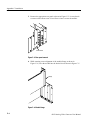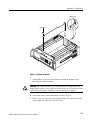
1
User Manual
AVG1
Analog Video Generator
070-9048-03
This document applies to firmware version 2.0
and above.
www.tektronix.com
Copyright © Tektronix, Inc. All rights reserved.
Tektronix products are covered by U.S. and foreign patents, issued and pending. Information in this publication supercedes
that in all previously published material. Specifications and price change privileges reserved.
Tektronix, Inc., P.O. Box 500, Beaverton, OR 97077
TEKTRONIX and TEK are registered trademarks of Tektronix, Inc.
WARRANTY
Tektronix warrants that the products that it manufactures and sells will be free from defects in materials and
workmanship for a period of one (1) year from the date of shipment. If a product proves defective during this
warranty period, Tektronix, at its option, either will repair the defective product without charge for parts and labor,
or will provide a replacement in exchange for the defective product.
In order to obtain service under this warranty, Customer must notify Tektronix of the defect before the expiration
of the warranty period and make suitable arrangements for the performance of service. Customer shall be
responsible for packaging and shipping the defective product to the service center designated by Tektronix, with
shipping charges prepaid. Tektronix shall pay for the return of the product to Customer if the shipment is to a
location within the country in which the Tektronix service center is located. Customer shall be responsible for
paying all shipping charges, duties, taxes, and any other charges for products returned to any other locations.
This warranty shall not apply to any defect, failure or damage caused by improper use or improper or inadequate
maintenance and care. Tektronix shall not be obligated to furnish service under this warranty a) to repair damage
resulting from attempts by personnel other than Tektronix representatives to install, repair or service the product;
b) to repair damage resulting from improper use or connection to incompatible equipment; c) to repair any
damage or malfunction caused by the use of non-Tektronix supplies; or d) to service a product that has been
modified or integrated with other products when the effect of such modification or integration increases the time
or difficulty of servicing the product.
THIS WARRANTY IS GIVEN BY TEKTRONIX IN LIEU OF ANY OTHER WARRANTIES, EXPRESS
OR IMPLIED. TEKTRONIX AND ITS VENDORS DISCLAIM ANY IMPLIED WARRANTIES OF
MERCHANTABILITY OR FITNESS FOR A PARTICULAR PURPOSE. TEKTRONIX’
RESPONSIBILITY TO REPAIR OR REPLACE DEFECTIVE PRODUCTS IS THE SOLE AND
EXCLUSIVE REMEDY PROVIDED TO THE CUSTOMER FOR BREACH OF THIS WARRANTY.
TEKTRONIX AND ITS VENDORS WILL NOT BE LIABLE FOR ANY INDIRECT, SPECIAL,
INCIDENTAL, OR CONSEQUENTIAL DAMAGES IRRESPECTIVE OF WHETHER TEKTRONIX OR
THE VENDOR HAS ADVANCE NOTICE OF THE POSSIBILITY OF SUCH DAMAGES.
Table of Contents
General Safety Summary . . . . . . . . . . . . . . . . . . . . . . . . . . . . . . . . . . .
Service Safety Summary . . . . . . . . . . . . . . . . . . . . . . . . . . . . . . . . . . . .
vii
ix
About This Manual . . . . . . . . . . . . . . . . . . . . . . . . . . . . . . . . . . . . . . . . . . . . . . .
Related Manuals . . . . . . . . . . . . . . . . . . . . . . . . . . . . . . . . . . . . . . . . . . . . . . . . .
Contacting Tektronix . . . . . . . . . . . . . . . . . . . . . . . . . . . . . . . . . . . . . . . . . . . . .
xi
xi
xii
Getting Started . . . . . . . . . . . . . . . . . . . . . . . . . . . . . . . . . . . . . . . . . . . .
1--1
Accessories . . . . . . . . . . . . . . . . . . . . . . . . . . . . . . . . . . . . . . . . . . . . . . . . . . . . .
Configuration . . . . . . . . . . . . . . . . . . . . . . . . . . . . . . . . . . . . . . . . . . . . . . . . . . .
Functional Check . . . . . . . . . . . . . . . . . . . . . . . . . . . . . . . . . . . . . . . . . . . . . . . .
1-- 2
1-- 2
1-- 3
Functional Overview . . . . . . . . . . . . . . . . . . . . . . . . . . . . . . . . . . . . . . .
2--1
Outputs . . . . . . . . . . . . . . . . . . . . . . . . . . . . . . . . . . . . . . . . . . . . . . . . . . . . .
Modulated Signals . . . . . . . . . . . . . . . . . . . . . . . . . . . . . . . . . . . . . . . . . . . .
Online Help . . . . . . . . . . . . . . . . . . . . . . . . . . . . . . . . . . . . . . . . . . . . . . . . .
2-- 2
2-- 2
2-- 2
Operating Procedures . . . . . . . . . . . . . . . . . . . . . . . . . . . . . . . . . . . . . .
2--3
Equipment Hookup . . . . . . . . . . . . . . . . . . . . . . . . . . . . . . . . . . . . . . . . . . . . . . .
Power On and Select the Module . . . . . . . . . . . . . . . . . . . . . . . . . . . . . . . . . . . .
Output Signal . . . . . . . . . . . . . . . . . . . . . . . . . . . . . . . . . . . . . . . . . . . . . . . . . . .
Enable/Disable the Output Signal . . . . . . . . . . . . . . . . . . . . . . . . . . . . . . . .
Select the Output Signal . . . . . . . . . . . . . . . . . . . . . . . . . . . . . . . . . . . . . . .
Active Signal Parameters . . . . . . . . . . . . . . . . . . . . . . . . . . . . . . . . . . . . . . . . . .
Signal Information . . . . . . . . . . . . . . . . . . . . . . . . . . . . . . . . . . . . . . . . . . . .
Text Overlay . . . . . . . . . . . . . . . . . . . . . . . . . . . . . . . . . . . . . . . . . . . . . . . .
Video Parameters . . . . . . . . . . . . . . . . . . . . . . . . . . . . . . . . . . . . . . . . . . . . .
Module Parameters . . . . . . . . . . . . . . . . . . . . . . . . . . . . . . . . . . . . . . . . . . . . . . .
Circle Overlay . . . . . . . . . . . . . . . . . . . . . . . . . . . . . . . . . . . . . . . . . . . . . . .
Timing . . . . . . . . . . . . . . . . . . . . . . . . . . . . . . . . . . . . . . . . . . . . . . . . . . . . .
Trigger . . . . . . . . . . . . . . . . . . . . . . . . . . . . . . . . . . . . . . . . . . . . . . . . . . . . .
2-- 3
2-- 4
2-- 5
2-- 5
2-- 5
2-- 7
2-- 8
2-- 9
2-- 11
2-- 13
2-- 14
2-- 15
2-- 16
Getting Started
Operating Basics
Syntax and Commands
Syntax . . . . . . . . . . . . . . . . . . . . . . . . . . . . . . . . . . . . . . . . . . . . . . . . . . .
3--1
Programming Model . . . . . . . . . . . . . . . . . . . . . . . . . . . . . . . . . . . . . . . . . . . . . .
SCPI Commands and Queries . . . . . . . . . . . . . . . . . . . . . . . . . . . . . . . . . . . . . .
3-- 1
3-- 3
Functional Command Groups . . . . . . . . . . . . . . . . . . . . . . . . . . . . . . .
3--5
MMemory . . . . . . . . . . . . . . . . . . . . . . . . . . . . . . . . . . . . . . . . . . . . . . . . . . . . . .
Output . . . . . . . . . . . . . . . . . . . . . . . . . . . . . . . . . . . . . . . . . . . . . . . . . . . . . . . . .
Sense . . . . . . . . . . . . . . . . . . . . . . . . . . . . . . . . . . . . . . . . . . . . . . . . . . . . . . . . . .
Source . . . . . . . . . . . . . . . . . . . . . . . . . . . . . . . . . . . . . . . . . . . . . . . . . . . . . . . . .
3-- 5
3-- 6
3-- 6
3-- 7
:OUTPut Commands . . . . . . . . . . . . . . . . . . . . . . . . . . . . . . . . . . . . . . .
3--9
Command Tree . . . . . . . . . . . . . . . . . . . . . . . . . . . . . . . . . . . . . . . . . . . . . . . . . .
:OUTPut:CIRCle:DIAMeter(?) . . . . . . . . . . . . . . . . . . . . . . . . . . . . . . . . . . . . .
3-- 9
3-- 10
AVG1 Analog Video Generator User Manual
i
Table of Contents
ii
:OUTPut:CIRCle:POSition:HORizontal(?) . . . . . . . . . . . . . . . . . . . . . . . . . . . .
:OUTPut:CIRCle:POSition:VERTical(?) . . . . . . . . . . . . . . . . . . . . . . . . . . . . . .
:OUTPut:CIRCle:STATe(?) . . . . . . . . . . . . . . . . . . . . . . . . . . . . . . . . . . . . . . . .
:OUTPut:CONFigure(?) . . . . . . . . . . . . . . . . . . . . . . . . . . . . . . . . . . . . . . . . . . .
:OUTPut:STATe(?) . . . . . . . . . . . . . . . . . . . . . . . . . . . . . . . . . . . . . . . . . . . . . . .
:OUTPut:TEXT:DATA(?) . . . . . . . . . . . . . . . . . . . . . . . . . . . . . . . . . . . . . . . . . .
:OUTPut:TEXT:STATe(?) . . . . . . . . . . . . . . . . . . . . . . . . . . . . . . . . . . . . . . . . .
:OUTPut:TEXT:POSition:HORizontal(?) . . . . . . . . . . . . . . . . . . . . . . . . . . . . .
:OUTPut:TEXT:POSition:VERTical(?) . . . . . . . . . . . . . . . . . . . . . . . . . . . . . . .
:OUTPut:TRIGger:CURSor:STATe(?) . . . . . . . . . . . . . . . . . . . . . . . . . . . . . . . .
:OUTPut:TRIGger:POSition:HORizontal(?) . . . . . . . . . . . . . . . . . . . . . . . . . . .
:OUTPut:TRIGger:POSition:HORizontal:STEP(?) . . . . . . . . . . . . . . . . . . . . . .
:OUTPut:TRIGger:POSition:VERTical(?) . . . . . . . . . . . . . . . . . . . . . . . . . . . . .
:OUTPut:TRIGger:POSition:VERTical:STEP(?) . . . . . . . . . . . . . . . . . . . . . . .
:OUTPut:TRIGger:TYPE(?) . . . . . . . . . . . . . . . . . . . . . . . . . . . . . . . . . . . . . . .
3-- 11
3-- 12
3-- 13
3-- 14
3-- 15
3-- 16
3-- 17
3-- 18
3-- 19
3-- 20
3-- 21
3-- 22
3-- 23
3-- 24
3-- 25
:SENSe Commands . . . . . . . . . . . . . . . . . . . . . . . . . . . . . . . . . . . . . . . .
3--27
Command Tree . . . . . . . . . . . . . . . . . . . . . . . . . . . . . . . . . . . . . . . . . . . . . . . . . .
:SENSe:CORRection:MDELay:HORizontal(?) . . . . . . . . . . . . . . . . . . . . . . . .
:SENSe:CORRection:MDELay:HORizontal:STEP(?) . . . . . . . . . . . . . . . . . . .
:SENSe:CORRection:MDELay:VERTical(?) . . . . . . . . . . . . . . . . . . . . . . . . . .
:SENSe:CORRection:MDELay:VERTical:STEP(?) . . . . . . . . . . . . . . . . . . . . .
3-- 27
3-- 28
3-- 29
3-- 30
3-- 31
:SOURce Commands . . . . . . . . . . . . . . . . . . . . . . . . . . . . . . . . . . . . . . .
3--33
Command Tree . . . . . . . . . . . . . . . . . . . . . . . . . . . . . . . . . . . . . . . . . . . . . . . . . .
:SOURce:MVIDeo:AMPLitude(?) . . . . . . . . . . . . . . . . . . . . . . . . . . . . . . . . . . .
:SOURce:MVIDeo:AMPLitude:STEP(?) . . . . . . . . . . . . . . . . . . . . . . . . . . . . .
:SOURce:MVIDeo:AVIDeo(?) . . . . . . . . . . . . . . . . . . . . . . . . . . . . . . . . . . . . . .
:SOURce:MVIDeo:AVIDeo:STEP(?) . . . . . . . . . . . . . . . . . . . . . . . . . . . . . . . .
:SOURce:MVIDeo:BURSt(?) . . . . . . . . . . . . . . . . . . . . . . . . . . . . . . . . . . . . . .
:SOURce:MVIDeo:BURSt:STEP(?) . . . . . . . . . . . . . . . . . . . . . . . . . . . . . . . . .
:SOURce:MVIDeo:BY(?) . . . . . . . . . . . . . . . . . . . . . . . . . . . . . . . . . . . . . . . . .
:SOURce:MVIDeo:BY:STEP(?) . . . . . . . . . . . . . . . . . . . . . . . . . . . . . . . . . . . .
:SOURce:MVIDeo :CHRoma:AMPLitude(?) . . . . . . . . . . . . . . . . . . . . . . . . . .
:SOURce:MVIDeo :CHRoma:AMPLitude:STEP(?) . . . . . . . . . . . . . . . . . . . . .
:SOURce:MVIDeo:CHRoma:PHASe(?) . . . . . . . . . . . . . . . . . . . . . . . . . . . . . .
:SOURce:MVIDeo:CHRoma:PHASe:STEP(?) . . . . . . . . . . . . . . . . . . . . . . . . .
:SOURce:MVIDeo:LUMinance(?) . . . . . . . . . . . . . . . . . . . . . . . . . . . . . . . . . .
:SOURce:MVIDeo:LUMinance:STEP(?) . . . . . . . . . . . . . . . . . . . . . . . . . . . . .
:SOURce:MVIDeo:PEDestal(?) . . . . . . . . . . . . . . . . . . . . . . . . . . . . . . . . . . . . .
:SOURce:MVIDeo:PEDestal:STEP(?) . . . . . . . . . . . . . . . . . . . . . . . . . . . . . . .
:SOURce:MVIDeo:RY(?) . . . . . . . . . . . . . . . . . . . . . . . . . . . . . . . . . . . . . . . . . .
:SOURce:MVIDeo:RY:STEP(?) . . . . . . . . . . . . . . . . . . . . . . . . . . . . . . . . . . . .
:SOURce:MVIDeo:SCH:PHASe(?) . . . . . . . . . . . . . . . . . . . . . . . . . . . . . . . . . .
:SOURce:MVIDeo:SCH:PHASe:STEP(?) . . . . . . . . . . . . . . . . . . . . . . . . . . . . .
:SOURce:MVIDeo:SUBCarrier:OFFSet(?) . . . . . . . . . . . . . . . . . . . . . . . . . . . .
:SOURce:MVIDeo:SUBCarrier:OFFSet:STEP(?) . . . . . . . . . . . . . . . . . . . . . . .
:SOURce:MVIDeo:SYNC(?) . . . . . . . . . . . . . . . . . . . . . . . . . . . . . . . . . . . . . . .
:SOURce:MVIDeo:SYNC:STEP(?) . . . . . . . . . . . . . . . . . . . . . . . . . . . . . . . . . .
:SOURce:MVIDeo:TIMEbase(?) . . . . . . . . . . . . . . . . . . . . . . . . . . . . . . . . . . . .
:SOURce:MVIDeo:TIMEbase:STEP(?) . . . . . . . . . . . . . . . . . . . . . . . . . . . . . .
:SOURce:VIDeo3:AMPLitude(?) . . . . . . . . . . . . . . . . . . . . . . . . . . . . . . . . . . .
:SOURce:VIDeo3:AMPLitude:STEP(?) . . . . . . . . . . . . . . . . . . . . . . . . . . . . . .
:SOURce:VIDeo3:AVIDeo(?) . . . . . . . . . . . . . . . . . . . . . . . . . . . . . . . . . . . . . .
3-- 34
3-- 35
3-- 36
3-- 37
3-- 38
3-- 39
3-- 40
3-- 41
3-- 42
3-- 43
3-- 44
3-- 45
3-- 46
3-- 47
3-- 48
3-- 49
3-- 50
3-- 51
3-- 52
3-- 53
3-- 54
3-- 55
3-- 56
3-- 57
3-- 58
3-- 59
3-- 60
3-- 61
3-- 62
3-- 63
AVG1 Analog Video Generator User Manual
Table of Contents
:SOURce:VIDeo3:AVIDeo:STEP(?) . . . . . . . . . . . . . . . . . . . . . . . . . . . . . . . . .
:SOURce:VIDeo3:BURSt(?) . . . . . . . . . . . . . . . . . . . . . . . . . . . . . . . . . . . . . . .
:SOURce:VIDeo3:BURSt:STEP(?) . . . . . . . . . . . . . . . . . . . . . . . . . . . . . . . . . .
:SOURce:VIDeo3:PEDestal(?) . . . . . . . . . . . . . . . . . . . . . . . . . . . . . . . . . . . . .
:SOURce:VIDeo3:PEDestal:STEP(?) . . . . . . . . . . . . . . . . . . . . . . . . . . . . . . . .
:SOURce:VIDeo3:SYNC(?) . . . . . . . . . . . . . . . . . . . . . . . . . . . . . . . . . . . . . . . .
:SOURce:VIDeo3:SYNC:STEP(?) . . . . . . . . . . . . . . . . . . . . . . . . . . . . . . . . . .
3-- 64
3-- 65
3-- 66
3-- 67
3-- 68
3-- 69
3-- 70
Appendix A: Specifications . . . . . . . . . . . . . . . . . . . . . . . . . . . . . . . . . .
A--1
Certifications . . . . . . . . . . . . . . . . . . . . . . . . . . . . . . . . . . . . . . . . . . . . . . . . . . .
Standards Conformance . . . . . . . . . . . . . . . . . . . . . . . . . . . . . . . . . . . . . . . . . . .
A-- 4
A-- 4
Appendix B: SCPI Conformance Information . . . . . . . . . . . . . . . . . .
B--1
Appendix C: Installation . . . . . . . . . . . . . . . . . . . . . . . . . . . . . . . . . . . .
C--1
Preventing Component Damage . . . . . . . . . . . . . . . . . . . . . . . . . . . . . . . . . . . . .
Module Installation . . . . . . . . . . . . . . . . . . . . . . . . . . . . . . . . . . . . . . . . . . . . . . .
Hardware Installation . . . . . . . . . . . . . . . . . . . . . . . . . . . . . . . . . . . . . . . . .
Signal Set Installation . . . . . . . . . . . . . . . . . . . . . . . . . . . . . . . . . . . . . . . . .
Configure Video Outputs . . . . . . . . . . . . . . . . . . . . . . . . . . . . . . . . . . . . . . . . . .
Signal Backup and Module Removal . . . . . . . . . . . . . . . . . . . . . . . . . . . . . . . . .
Required Equipment . . . . . . . . . . . . . . . . . . . . . . . . . . . . . . . . . . . . . . . . . .
Signal Backup . . . . . . . . . . . . . . . . . . . . . . . . . . . . . . . . . . . . . . . . . . . . . . .
Module Removal . . . . . . . . . . . . . . . . . . . . . . . . . . . . . . . . . . . . . . . . . . . . .
C-- 1
C-- 2
C-- 2
C-- 6
C-- 9
C-- 10
C-- 10
C-- 10
C-- 10
Appendices
Glossary and Index
AVG1 Analog Video Generator User Manual
iii
Table of Contents
List of Figures
iv
Figure 2--1: Menu structure for the AVG1 Generator module . . . . .
2--1
Figure 3--1: Example of a SCPI subsystem hierarchy . . . . . . . . . . . .
3--3
Figure C--1: TG 2000 Platform mainframe rear panel,
showing slot numbering . . . . . . . . . . . . . . . . . . . . . . . . . . . . . . . . .
Figure C--2: Top cover removal . . . . . . . . . . . . . . . . . . . . . . . . . . . . . .
Figure C--3: Rear panel removal . . . . . . . . . . . . . . . . . . . . . . . . . . . . .
Figure C--4: Module flange . . . . . . . . . . . . . . . . . . . . . . . . . . . . . . . . . .
Figure C--5: Module installation . . . . . . . . . . . . . . . . . . . . . . . . . . . . .
Figure C--6: Top screw . . . . . . . . . . . . . . . . . . . . . . . . . . . . . . . . . . . . . .
C--2
C--3
C--4
C--4
C--5
C--6
AVG1 Analog Video Generator User Manual
Table of Contents
List of Tables
Table 1--1: Standard and Optional Accessories . . . . . . . . . . . . . . . . .
1--2
Table 2--1: AVG1 Output Configurations . . . . . . . . . . . . . . . . . . . . . .
2--2
Table 3--1: :MMEMory commands . . . . . . . . . . . . . . . . . . . . . . . . . . .
Table 3--2: :OUTPut Commands . . . . . . . . . . . . . . . . . . . . . . . . . . . . .
Table 3--3: :SENSe Commands . . . . . . . . . . . . . . . . . . . . . . . . . . . . . .
Table 3--4: :SOURce Commands . . . . . . . . . . . . . . . . . . . . . . . . . . . . .
3--5
3--6
3--6
3--7
Table A--1: Electrical specifications . . . . . . . . . . . . . . . . . . . . . . . . . .
Table A--2: Certifications and compliances . . . . . . . . . . . . . . . . . . . .
A--1
A--4
Table B--1: SCPI Conformance Information . . . . . . . . . . . . . . . . . . .
B--1
Table C--1: Module slot assignments . . . . . . . . . . . . . . . . . . . . . . . . . .
C--2
AVG1 Analog Video Generator User Manual
v
Table of Contents
vi
AVG1 Analog Video Generator User Manual
General Safety Summary
Review the following safety precautions to avoid injury and prevent damage to
this product or any products connected to it.
Only qualified personnel should perform service procedures.
To avoid potential hazards, use this product only as specified.
Injury Precautions
Avoid Electric Overload. To avoid electric shock or fire hazard, do not apply a
voltage to a terminal that is outside the range specified for that terminal.
Product Damage
Precautions
Do Not Operate With Suspected Failures. If you suspect there is damage to this
product, have it inspected by qualified service personnel.
Symbols and Terms
Terms in this Manual. These terms may appear in this manual:
WARNING. Warning statements identify conditions or practices that could result
in injury or loss of life.
CAUTION. Caution statements identify conditions or practices that could result in
damage to this product or other property.
Terms on the Product. These terms may appear on the product:
DANGER indicates an injury hazard immediately accessible as you read the
marking.
WARNING indicates an injury hazard not immediately accessible as you read the
marking.
CAUTION indicates a hazard to property including the product.
Symbols on the Product. The following symbols may appear on the product:
DANGER
High Voltage
AVG1 Analog Video Generator User Manual
Protective Ground
(Earth) Terminal
ATTENTION
Refer to Manual
Double
Insulated
vii
General Safety Summary
Certifications and
Compliances
viii
Refer to the specifications section for a listing of certifications and compliances
that apply to this product.
AVG1 Analog Video Generator User Manual
Service Safety Summary
Only qualified personnel should perform service procedures. Read this Service
Safety Summary and the General Safety Summary before performing any service
procedures.
Do Not Service Alone. Do not perform internal service or adjustments of this
product unless another person capable of rendering first aid and resuscitation is
present.
Disconnect Power. To avoid electric shock, disconnect the main power by means
of the power cord or, if provided, the power switch.
Use Care When Servicing With Power On. Dangerous voltages or currents may
exist in this product. Disconnect power, remove battery (if applicable), and
disconnect test leads before removing protective panels, soldering, or replacing
components.
To avoid electric shock, do not touch exposed connections.
AVG1 Analog Video Generator User Manual
ix
Service Safety Summary
x
AVG1 Analog Video Generator User Manual
Preface
This manual documents the capabilities, specifications, operation, and installation of the AVG1 Generator module.
About This Manual
This manual is composed of the following sections:
H
Getting Started provides a product description, incoming inspection
procedure, and a standard and optional accessories list. It also provides
procedures on how to install signal sets.
H
Operating Basics describes the windowed menu interface and how to control
the module through the interface in conjunction with the front panel.
H
Syntax and Commands defines the syntax used in command descriptions,
presents a list of all command subsystems, and presents detailed descriptions
of all programming commands.
H
Appendices provides additional information including the Specifications and
hardware installation procedures.
Related Manuals
The following documents are also available:
H
The AVG1 Analog Video Generator Service Manual describes how to service
the AVG1 module. This optional manual must be ordered separately.
H
The TG 2000 Signal Generation Platform User Manual describes how to use
the TG 2000 Platform. It also contains information about SCPI commands,
programming structure, and status and events for the platform. Some of this
information applies to all generator modules, including the AVG1 Generator
module. This manual is a standard accessary to the TG 2000 Platform
mainframe.
H
The TG 2000 Signal Generation Platform Service Manual describes how to
service the mainframe to the module level and provides general information
about servicing generator modules. This optional manual must be ordered
separately.
H
A module user manual is included with each optional module. Contact your
Tektronix representative for a list of generator and special function modules.
AVG1 Analog Video Generator User Manual
xi
Preface
Contacting Tektronix
Product
Support
For questions about using Tektronix measurement products, call
toll free in North America:
1-800-833-9200
6:00 a.m. -- 5:00 p.m. Pacific time
Or contact us by e-mail:
[email protected]
For product support outside of North America, contact your
local Tektronix distributor or sales office.
Service
support
Tektronix offers a range of services, including Extended
Warranty Repair and Calibration services. Contact your local
Tektronix distributor or sales office for details.
For a listing of worldwide service centers, visit our web site.
xii
Toll-free
Number
In North America:
1-800-833-9200
An operator can direct your call.
Postal
Address
Tektronix, Inc.
Department or name (if known)
P.O. Box 500
Beaverton, OR 97077
USA
Web site
www.tektronix.com
AVG1 Analog Video Generator User Manual
Getting Started
Getting Started
The AVG1 Analog Video Generator module is designed to be installed in the
TG 2000 Signal Generation Platform.
The module is a high accuracy, multiformat analog video test signal generator.
The signal generation architecture is 12-bit, 27 MHz component with digital
modulation for composite signals. This ensures high accuracy, distortion free
signals within a 6 MHz video bandwidth.
This module provides three channel outputs and one trigger output. The trigger
output can be used to trigger other video equipment or an oscilloscope.
The module can generate signals in these component and composite formats:
H
NTSC
H
SECAM
H
PAL
H
GBR
H
PAL-D
H
YC plus composite
H
PAL-M
H
Y, B-Y, and R-Y
H
PAL-N
You can create other formats with the SDP2000 program. However, the output
reconstruction filters are optimized for a 27 MHz sampling frequency.
To adjust the amplitude or time base offset parameters, follow the procedure for
Video Parameters on page 2--11. Several amplitude parameters of the signal can
be adjusted, such as luminance amplitude and chrominance gain.
The underlying time base used to generate signals can also be adjusted. When
this parameter is adjusted, it adjusts every component of the active video signal,
such as line length, subcarrier frequency if applicable, and rise time. The signal
also becomes unframed; it has no phase relationship with the genlock input
(AGL1 Generator module). Two modules with the same time base offset value
are not necessarily framed together.
AVG1 Analog Video Generator User Manual
1- 1
Getting Started
Accessories
Table lists standard and optional accessories for the module. Standard accessories
are included with the module, and optional accessories are available for purchase
to use with the module.
Table 1- 1: Standard and Optional Accessories
Accessory
Typo of accessory
Part number
AVG1 Analog Video Generator User Manual
Standard
070-9048-XX
T-10 Torx Tip
Standard
003-1604-XX
Screws (2 ea.)
Standard
211-0725-XX
Blank rear panel
Standard
333-4113-XX
AVG1 Analog Video Generator Service Manual Optional
070-9677-XX
Configuration
The module does not require any hardware configuration. However, you can
configure the channel outputs. Refer to Configure the Outputs on page C--9 for
instructions.
1- 2
AVG1 Analog Video Generator User Manual
Getting Started
Functional Check
For this procedure, you will need a television monitor, a 75 Ω coaxial cable, and
a 75 Ω termination.
To determine if the module is operating correctly, follow these steps:
1. If the module is not installed into the platform, use the installation procedures on page C--2.
2. Power on the platform. The platform runs a self test on all modules.
3. To determine if the self test was successful, push the Module button. Check
the display for the icon that represents the module you are inspecting. If the
module does not appear, refer to Troubleshooting in the AVG1 Analog Video
Generator Service Manual.
4. If your module was ordered separately and you installed it in the platform,
and you do not have another AVG1 Generator module already installed in the
platform, install signal sets using the procedures on page C--6.
5. Wait 20 minutes for the instrument to warm up at nominal ambient
temperature. (Signal amplitude and DC offset may vary slightly over a
range of temperatures.)
6. Perform self calibration as follows:
a. Terminate the three rear-panel signal outputs.
b. Push the Utilities button and then touch Module Self Cal.
NOTE. The original calibration file will be replaced by the new one.
c. Touch the Self Cal icon for the module you are testing
d. Touch Start Cal. The Self Cal takes 2 to 5 minutes depending on the
module. An error message indicates a failed calibration. If the Self Cal
fails, contact your Tektronix Representative for assistance.
e. When the Self Cal is successful, proceed to step 7.
7. Select a signal set and output signal that are compatible with your monitor. A
composite signal is preferred because it tests more of the module’s hardware.
8. Connect the rear-panel Output 1 connector to the television monitor’s input.
9. Configure the channel outputs for composite as follows:
a. Push the Test Signals front-panel button.
b. Touch Module Parameters.
AVG1 Analog Video Generator User Manual
1- 3
Getting Started
c. Touch Output Config.
d. Select Composite All Channels.
10. Adjust your monitor to view the signal. Check that the signal appears as
expected. For example, if you selected a color bar signal output, check for a
color bar signal on the monitor display.
11. Move the output cable to each of the channel output connectors in turn to
ensure that the appropriate signal appears.
12. Move the cable back to Output 1.
13. Select a different test signal in the same signal set and check that the
displayed signal changes. You only need to do this on Output 1.
1- 4
AVG1 Analog Video Generator User Manual
Operating Basics
Functional Overview
This section provides an overview of the AVG1 Generator module. If you are not
familiar with the operation of the TG 2000 Signal Generation Platform, refer to
the TG 2000 Signal Generation Platform User Manual before reading this
section.
Figure 2--1 shows the module’s menu structure.
Modules window
Push Modules
button
Touch AVG1 module
Push Edit button
Edit Module window
Touch Rename
Module
Signal Sets window
Touch Module
Parameters
Touch desired signal set
(usually represents format)
Rename Module window
Test Signals window
Enter new name for
module
To select output signal, touch
desired Test Signal icon until
desired signal is selected
Touch Module
Parameters
Module Parameters window
Touch Output to
enable or disable the
module output signal
Touch Module Timing,
Circle Overlay, Trigger
Output, or Output Config
Push Signal
Sets button
Push Test
Signals button
Touch Active
Signal Parameters
Active Signal Parameters window
Touch Video, Text Overlay or
Signal Information
Module Timing, Circle Overlay, Trigger, or
Output Config window
Video Parameters, Text Overlay, or
Signal Information window
Set module timing with respect to the BG1
module, create circle overlay, configure trigger or
signal outputs
Set video parameters, adjust text on
signal, or view information about the
selected signal
Figure 2- 1: Menu structure for the AVG1 Generator module
AVG1 Analog Video Generator User Manual
2- 1
Functional Overview
Outputs
This module has four BNC connectors on the rear panel: one Trigger Out and
three channel outputs. The channel outputs can be configured as shown in
Table 2--1. To configure the outputs, refer to Configure the Outputs on page C--9.
Table 2- 1: AVG1 Output Configurations
Modulated Signals
Connector
GBR
Y, B-Y, R-Y
Hardware modulated
Software modulated
Channel 1
G
Y
Y or Composite
Composite 1
Channel 2
B
B-Y
C or Composite
Composite 2
Channel 3
R
R-Y
Composite
Composite 3
There are two methods of signal generation for composite signals: hardware
modulation and software modulation. Hardware modulated signals are preferred
when the lowest amount of differential phase and differential gain is required.
Hardware modulated signals use less memory than software modulated signals;
and signal parameter adjustments are more complete and responsive.
Chroma quantization makes differential phase and differential gain measurements more difficult when using modulated ramp, modulated 5 step, and
modulated 10 step signals. To minimize this effect, adjust the Chroma Gain
Video Parameter to 102.0%. Refer to page 2--11.
Software modulated signals are preferred when three different signals are
supplied by the module at one time. PAL is not supported in this mode, because
of the 25 Hz offset.
Online Help
2- 2
Push the front-panel HELP button to display a help window. The help window
describes the window you were using when you pushed HELP.
AVG1 Analog Video Generator User Manual
Operating Procedures
This section is organized into the following main topics:
H
Power on the mainframe and select the module
H
Select an output signal
H
Active signal parameters
H
Module parameters
Refer to Figure 2--1 on page 2--1 for information on how to access the appropriate windows for these procedures.
Equipment Hookup
No special test equipment is necessary for these procedures, but it will be helpful
to view the signals on a monitor. To do this, connect the module’s signal output
to a television monitor, using a 75 Ω cable and a 75 Ω termination.
AVG1 Analog Video Generator User Manual
2- 3
Operating Procedures
Power On and Select the Module
After the module is installed in the mainframe, and the mainframe is installed in
the rack or other location where it will be used, power on the mainframe and
select the module by following these steps:
1. Set the rear-panel power switch to the ON position.
2. Press the front-panel POWER switch if necessary.
3. Wait for a few seconds as the mainframe executes confidence tests on the
mainframe and modules. Check for any error messages that might appear.
4. When self tests are complete, the instrument displays icons representing each
installed generator module. If an installed module is not represented, refer to
Troubleshooting in the AVG1 Analog Video Generator Service Manual.
NOTE. The illustrations in these procedures show the factory default name
(AVG1:X where X represents the slot number in which the module is installed).
However, because you can rename the module, your icons may display a different
name. Refer to the TG 2000 Signal Generation Platform User Manual for
information about editing the module name.
5. Since you have just powered on the mainframe, the Modules window (shown
below) is displayed. To select the module at other times, push the front-panel
Modules button.
6. Touch the module icon on the display (or push the Signal Sets button if the
desired icon is already highlighted). The installed signal sets for the module
appear. Selections you make after this will pertain to the AVG1 Generator
module.
2- 4
AVG1 Analog Video Generator User Manual
Operating Procedures
Output Signal
The output signal is supplied on the two rear-panel serial outputs. To configure
the outputs, refer to Appendix C.
Enable/Disable the
Output Signal
If you disable the module output, it releases all system resources used by this
module.
1. Select the AVG1 Generator module, if not already selected.
2. Push the Test Signals button.
3. Touch Module Parameters at the bottom of the screen. The Module
Parameters window (shown on page 2--13) appears.
4. Touch the Output icon to toggle the state of the module’s output signal.
5. Touch Quit to exit.
Select the Output Signal
Use the following procedure to select the module’s output test signal. You can
select any of the AVG1 signals that are loaded in your instrument.
1. Push the Signal Sets button to open the window shown below. Check that
there is an icon for each installed signal set. If your signal sets are not
installed, refer to Signal Set Installation on page C--6.
AVG1 Analog Video Generator User Manual
2- 5
Operating Procedures
2. Touch the desired signal set on the display. The Test Signals window for the
selected signal set appears. In the following example, NTSC is selected.
3. Each test signal icon in the Test Signals window represents one or more
signals. In this example, the 100% Color Bars signal is being generated.
4. To change to another Color Bar signal, touch the Color Bar repeatedly to
cycle through all available signals. You can also display the complete list of
test signals available under a selected test-signal icon by touching the list
box or by rotating the Navigation knob, and then select a signal by pressing
the front-panel Select button.
5. To change to a different signal type, such as Linearity, touch the corresponding icon on the display. Then select the signal as shown in step 4.
6. To select the output signal using the List window, display the list of test
signals by pushing the front-panel List button. Use the Navigation arrow
keys to highlight the module and signal, and then push the Select button.
2- 6
AVG1 Analog Video Generator User Manual
Operating Procedures
Active Signal Parameters
The following procedures discuss windows that are accessed through the Active
Signal Parameters window, shown below. Changes that you make to parameters
in any of these windows affect only the active signal.
To enter the Active Signal Parameters window for the AVG1 Generator module,
follow these steps:
1. Select the AVG1 Generator module, if not already selected.
2. Push the Test Signals button.
3. Touch Active Signal Parameters at the bottom of the screen. The Active
Signal Parameters window appears, as shown below.
AVG1 Analog Video Generator User Manual
2- 7
Operating Procedures
Signal Information
You can view detailed information about the active signal.
1. In the Active Signal Parameters window shown on page 2--7, touch Signal
Information.
2. View the signal information, as shown in the following illustration.
2- 8
AVG1 Analog Video Generator User Manual
Operating Procedures
Text Overlay
You can enter text that overlays your displayed test signal. When turning text on
or off, you are turning text on or off for all test signals that have overlaid text.
Touching Reset returns the text, horizontal and vertical to previously saved
values.
To enter and position text, follow these steps:
1. In the Active Signal Parameters window, shown on page 2--7, touch Text
Overlay to enter the Signal Text window. The Signal Text window is shown
in the following illustration.
2. Touch Edit Text to enter the text entry window as shown in the following
illustration.
AVG1 Analog Video Generator User Manual
2- 9
Operating Procedures
3. Enter text as follows:
a. Touch the desired letters on the display.
b. Touch Return if you want to enter a new line.
c. Touch the list box at the top of the window to see all the text entered.
d. Touch OK when text entry is complete. The Signal Text Overlay menu
returns.
4. Touch Text On/Off to display the text on your monitor. The Signal Text
Overlay menu lists the text you previously entered, as shown in the
following illustration.
5. Touch H Pos and enter a value from the keypad, or rotate the knob until the
desired horizontal position is reached.
6. Touch V Pos and enter a value from the keypad, or rotate the knob until the
desired vertical position is reached.
7. If you want to reset the text, horizontal and vertical to previously saved
values, touch Reset.
8. Touch Quit/Save. A dialog box appears; you can enter a new name for the
test signal. If you touch Save, the original test signal is modified to include
the overlaid text and an underscore is added to the front of the name. If you
touch Save As, the platform displays a text entry window in which you can
rename the signal.
2- 10
AVG1 Analog Video Generator User Manual
Operating Procedures
Video Parameters
You can adjust the signal parameters of the currently selected (active) test signal,
and then rename and save a test signal. The original and the modified signal are
both saved.
NOTE. To modify and save a Tektronix generated signal, you must rename it.
When you rename and save a signal, both the original and the modified signals
are saved.
To modify video parameters, follow these steps:
1. In the Active Signal Parameters window, shown on page 2--7, touch Video
Parameters.
2. The Video Parameters window opens, as shown below. (Different signals
may display a different list in this window.) Use the Navigation arrow keys
to select the parameter you want to change. The Time Base Offset parameter
is described on page 1--1.
3. Enter a value using the knob or keypad, and then touch Quit/Save.
4. If you want to reset all the parameters to their previously saved values, touch
Reset.
NOTE. If you change the value for Active Video Gain, the Luma Ampl, Chroma
Gain, Active R--Y Ampl and Active B--Y Ampl values also change. If you change
the value for Chroma Gain, the Active R--Y Ampl and Active B--Y Ampl values
also change.
AVG1 Analog Video Generator User Manual
2- 11
Operating Procedures
5. Press Quit/Save. A dialog box appears.
NOTE. If you modify any signal that was shipped on the factory disks, the
platform adds an underscore to the front of the name.
6. Touch Save As. A text entry window appears, as shown in the following
illustration. The platform suggests a new test signal name for you by adding
an underscore to the front of the current name.
7. If you want to use the displayed name, touch OK.
8. To use a different name, do the following:
a. From the Text Entry window, delete the suggested name using the
BS key, and then enter new text. (You cannot backspace over an
underscore character.)
b. Touch Set 1 or Set 2 to provide additional sets of characters.
c. Touch OK when text is complete.
9. Touch Quit/Save to exit the window.
2- 12
AVG1 Analog Video Generator User Manual
Operating Procedures
Module Parameters
The following procedures discuss windows that are accessed through the Module
Parameters window, shown below. Changes that you make to parameters in any
of these windows affect the entire module.
To enter the Module Parameters window for the AVG1 Generator module, follow
these steps:
1. Select the AVG1 Generator module, if not already selected.
2. Push the Test Signals button.
3. Touch Module Parameters at the bottom of the screen. The Module
Parameters window appears, as shown below.
4. Another way to access this window is to push the Modules button, ensure
that the module is highlighted, push the Edit button, and then touch Module
Parameters.
AVG1 Analog Video Generator User Manual
2- 13
Operating Procedures
Circle Overlay
You can define a circle that is overlaid on the test signal output. The Circle
Overlay parameters settings affect all test signals from this module. Entered
values are constant, regardless of the test signal or video standard.
To define a circle overlay, follow these steps:
1. In the Module Parameters window, shown on page 2--13, touch Circle
Overlay to enter the Circle Overlay window. The Circle Overlay window is
shown in the following illustration.
.
2. Touch On/Off to turn on the circle overlay.
3. Touch Diam.
4. Rotate the Navigation knob or enter a value from the keypad. Rotating the
knob changes the diameter by percentages of Active Picture Height (APH).
5. Select H Pos and rotate the Navigation knob to move the circle horizontally
by a percentage of APH.
NOTE. As you change the values using the knob, the circle is drawn in a quick
draw mode. Once values stop changing, the overlay is redrawn in full resolution.
6. Select V Pos and rotate the knob to move the circle vertically by a percentage of APH.
7. If you want to reset the values, touch Reset All. This will set the diameter,
horizontal, and vertical to 90%, 0, and 0 respectively.
8. Press Quit to exit the window.
2- 14
AVG1 Analog Video Generator User Manual
Operating Procedures
Timing
You can set the horizontal and vertical timing of this module with respect to the
BG1 Generator module. Changes you make to timing affect all signals for the
AVG1 Generator module.
1. In the Module Parameters window, shown on page 2--13, touch Timing. The
timing window appears, as shown in the following illustration.
2. Touch Vertical on the display. The default setting is 0 lines
3. Rotate the navigation knob counterclockwise to advance the timing or
clockwise to delay the timing. You can also enter values from the keypad and
push the Select button.
4. Touch H Feel (horizontal resolution) to select Coarse resolution. Coarse
increments are equal to a full cycle of the clock.
5. Touch Horizontal. The default is 0.000 sec.
6. Rotate the Navigation knob counterclockwise to advance the timing or
clockwise to delay the timing. Set the timing close to the desired value.
7. Touch H Feel (horizontal resolution) to select Fine resolution. Fine
resolution move in subclock cycle increments.
8. Rotate the Navigation knob counterclockwise to advance the timing or
clockwise to delay the timing. Set the final value.
9. You can also select Vertical or Horizontal and enter values from the keypad.
10. If you want to reset the values, touch Reset All. This sets horizontal and
vertical to 0.000 sec and 0 lines.
11. Press Quit to exit the window.
AVG1 Analog Video Generator User Manual
2- 15
Operating Procedures
Trigger
You can select one of the following types of Trigger signals to send to the rear
panel Trigger BNC connector:
H
Horizontal. One trigger pulse per line at the location entered.
H
Vertical. One trigger pulse per color frame at beginning of the entered line.
H
Pixel. One trigger pulse per color frame at the intersection of the horizontal
and vertical trigger.
NOTE. Triggers are active throughout the line. However, cursors are only active
during active video.
To select the trigger output, follow these steps:
1. In the Module Parameters window, shown on page 2--13, touch Trigger to
enter the Trigger window, shown below.
2. Turn on the cursor by touching the On/Off on the display. A cursor provides
line and pixel selection anywhere within the frame.
3. Touch Type on the display until the desired type of trigger is displayed:
H
Horizontal (one trigger pulse per line at location entered)
H
Vertical (one trigger pulse per color frame at beginning of line entered)
H
Pixel (one trigger pulse per color frame at intersection of horizontal and
vertical trigger)
4. If the type is horizontal or pixel, touch H Pos us (to adjust horizontal
position by time) or H Pos samples (to adjust horizontal position by
2- 16
AVG1 Analog Video Generator User Manual
Operating Procedures
samples). Rotate the Navigation knob until the desired position is reached,
or enter a value using the keypad and push enter.
5. If the type is vertical or pixel, touch V Pos and rotate the Navigation knob
until the desired line is reached. You can also enter a value using the keypad.
6. Touch Reset All if you want to set all the parameters to the default settings
(H Pos to zero and V Pos to 1).
7. Touch Quit to exit the window.
AVG1 Analog Video Generator User Manual
2- 17
Operating Procedures
2- 18
AVG1 Analog Video Generator User Manual
Syntax and Commands
Syntax
This section contains information on the Standard Commands for Programmable
Instruments (SCPI) and the programming structure you can use to program your
module.
Programming Model
Specific conditions must exist before programming commands will affect the test
signal generated by a module.
Addressing Module Test
Signals
The following two steps must be performed before the test module will respond
to signal parameter commands.
1. Select the module to be addressed before executing any commands. Many of
the commands are shared by several modules and will be accepted without a
reported error.
2. Enable the module using the :OUTPut:STATe ON command. You must
enable the output state of the module before you change the test signal
parameters.
Command Arguments
Many commands will accept either string or numeric arguments. For example: a
Boolean argument can either be “1” or “ON“.
Signal parameter commands that have a :STEP node can accept either a numeric
value or they can accept a string argument that refers to the :STEP increment.
Signal parameter commands with a :STEP node will accept the following strings
in addition to a numeric value:
UP. Use this argument to increase the parameter value one increment as defined
by the :STEP value.
DOWN. Use this argument to decrease the parameter value one increment as
defined by the :STEP value.
AVG1 Analog Video Generator User Manual
3- 1
Syntax
MINimum. Use this argument to set the parameter value to the minimum
acceptable value.
MAXimum. Use this argument to set the parameter value to the maximum
acceptable value.
DEFault. Use this argument to set the parameter value to the default value.
Argument Example
The following example demonstrates the effect of each argument used with a
step value.
1. :INSTrument:SELect ”AVG1:#” selects the analog video generator module
located in the slot number indicated by the “#” symbol.
2. :OUTPut:STATe ON enables the module and displays the loaded test signal.
3. :OUTPut:CIRCle:STATe ON displays a circle on the video display.
NOTE. :OUTPut:CIRCle:DIAMeter uses an argument that is the percent of
picture height.
4. :OUTPut:CIRCle:DIAMeter DEFault sets the circle diameter to 90 percent
of the screen height.
5. :OUTPut:CIRCle:DIAMeter:STEP 10 sets the step increment to 10 percent.
6. :OUTPut:CIRCle:DIAMeter DOWN changes the circle diameter to
80 percent of the screen height.
7. :OUTPut:CIRCle:DIAMeter 50 changes the circle diameter to 50 percent of
the screen height.
8. :OUTPut:CIRCle:DIAMeter MAXimum changes the circle diameter to
100 percent of the screen height.
9. :OUTPut:CIRCle:DIAMeter MINimum changes the circle diameter to
0 percent of the screen height.
10. :OUTPut:CIRCle:DIAMeter UP changes the circle diameter to 10 percent of
the screen height.
3- 2
AVG1 Analog Video Generator User Manual
Syntax
SCPI Commands and Queries
SCPI is a standard created by a consortium that provides guidelines for remote
programming of instruments. These guidelines provide a consistent programming environment for instrument control and data transfer. This environment
uses defined programming messages, instrument responses, and data format
across all SCPI instruments, regardless of manufacturer. The AVG1 Generator
module uses a command language based on the SCPI standard.
The SCPI language is based on a hierarchical or tree structure (see Figure 3--1)
that represents a subsystem. The top level of the tree is the root node; it is
followed by one or more lower-level nodes.
STATe
OUTPut
Root node
CIRCle
Lower-level
nodes
DIAMeter
POSition
Figure 3- 1: Example of a SCPI subsystem hierarchy tree
You can create commands and queries from these subsystem hierarchy trees.
Commands specify actions for the instrument to perform. Queries return
measurement data and information about parameter settings.
For more information on creating SCPI commands, programming structure, and
status and events, refer to the TG 2000 Signal Generation Platform User
Manual.
AVG1 Analog Video Generator User Manual
3- 3
Syntax
3- 4
AVG1 Analog Video Generator User Manual
Functional Command Groups
This section describes the commands in general categories. Commands to the
module are divided into the following groups:
H
MMEMory (see TG 2000 Signal Generation Platform User Manual)
H
OUTPut
H
SENSe
H
SOURce
Items followed by question marks are queries; items without question marks are
commands. Some items in this section have a question mark in parentheses (?) in
the command header section; this indicates that the item can be both a command
and a query.
MMemory
Two MMEMory commands are listed here for your reference. You can use these
to set and query the output test signal for the module. Detailed information for
using these commands (as well as other commands that can be used with the
entire platform) are located in the TG 2000 Signal Generation Platform User
Manual.
Table 3- 1: :MMEMory commands
Command
Description
:MMEMory:LOAD:SIGNal
Load a signal into a module and identify that signal as the active
signal (output signal) for that module
:MMEMory:SIGNal:ACTive?
List the active signal (output signal) for a module
AVG1 Analog Video Generator User Manual
3- 5
Functional Command Groups
Output
Use these commands to select the output characteristics of the module.
Table 3- 2: :OUTPut Commands
Command
Description
:OUTPut:CIRCle:DIAMeter(?)
Set or query circle diameter
:OUTPut:CIRCle:STATe(?)
Set or query circle
:OUTPut:CIRCle:POSition:HORizontal(?)
Set or query circle horizontal position
:OUTPut:CIRCle:POSition:VERTical(?)
Set or query circle vertical position
:OUTPut:CONFigure(?)
Set or query module configuration
:OUTPut:SIGNal(?)
Set or query output signal
:OUTPut:STATe(?)
Set or query module output
:OUTPut:TEXT:DATA(?)
Set or query current text string
:OUTPut:TEXT:POSition:HORizontal(?)
Set or query text horizontal position
:OUTPut:TEXT:POSition:VERTical(?)
Set or query text vertical position
:OUTPut:TEXT:STATe(?)
Set or query text
:OUTPut:TRIGger:TYPE(?)
Set or query trigger mode
:OUTPut:TRIGger:CURSor:STATe(?)
Set or query trigger cursor
:OUTPut:TRIGger:POSition:HORizontal(?)
Set or query trigger horizontal position
:OUTPut:TRIGger:POSition:HORizontal:STEP(?)
Set or query horizontal position step size
:OUTPut:TRIGger:POSition:VERTical(?)
Set or query trigger vertical position
:OUTPut:TRIGger:POSition:VERTical:STEP(?)
Set or query vertical position step size
Sense
Use these commands to adjust the signal timing.
Table 3- 3: :SENSe Commands
Command
Description
:SENSe:CORRection:MDELay:HORizontal(?)
Set or query horizontal time delay
:SENSe:CORRection:MDELay:HORizontal:STEP(?)
Set or query horizontal step size
:SENSe:CORRection:MDELay:VERTical(?)
Set or query vertical time delay
:SENSe:CORRection:MDELay:VERTical:STEP(?)
Set or query vertical step size
3- 6
AVG1 Analog Video Generator User Manual
Functional Command Groups
Source
Use these commands to define the signal parameters for the module.
Table 3- 4: :SOURce Commands
Command
Description
:SOURce:MVIDeo:AMPLitude(?)
Set or query video signal amplitude
:SOURce:MVIDeo:AMPLitude:STEP(?)
Set or query video signal amplitude step size
:SOURce:MVIDeo:AVIDeo(?)
Set or query active video amplitude
:SOURce:MVIDeo:AVIDeo:STEP(?)
Set or query active video amplitude step size
:SOURce:MVIDeo:BURSt(?)
Set or query burst pulse amplitude
:SOURce:MVIDeo:BURSt:STEP(?)
Set or query burst pulse amplitude step size
:SOURce:MVIDeo:BY(?)
Set or query channel BY component amplitude
:SOURce:MVIDeo:BY:STEP(?)
Set or query channel BY step size
:SOURce:MVIDeo:CHRoma:AMPLitude(?)
Set or query channel chroma amplitude
:SOURce:MVIDeo:CHRoma:AMPLitude:STEP(?)
Set or query channel chroma amplitude step size
:SOURce:MVIDeo:CHRoma:PHASe(?)
Set or query channel chroma phase
:SOURce:MVIDeo:CHRoma:PHASe:STEP(?)
Set or query channel chroma phase step size
:SOURce:MVIDeo:LUMinance(?)
Set or query channel luminance amplitude
:SOURce:MVIDeo:LUMinance:STEP(?)
Set or query channel luminance amplitude step size
:SOURce:MVIDeo:PEDestal(?)
Set or query pedestal amplitude
:SOURce:MVIDeo:PEDestal:STEP(?)
Set or query pedestal amplitude step size
:SOURce:MVIDeo:RY(?)
Set or query channel RY component amplitude
:SOURce:MVIDeo:RY:STEP(?)
Set or query channel RY step size
:SOURce:MVIDeo:SCH:PHASe(?)
Set or query channel
:SOURce:MVIDeo:SCH:PHASe:STEP(?)
Set or query channel
:SOURce:MVIDeo:SUBCarrier:OFFSet(?)
Set or query channel
:SOURce:MVIDeo:SUBCarrier:OFFSet:STEP(?)
Set or query channel
:SOURce:MVIDeo:SYNC(?)
Set or query sync pulse amplitude
:SOURce:MVIDeo:SYNC:STEP(?)
Set or query sync pulse amplitude step size
:SOURce:MVIDeo:TIMEbase(?)
Set or query module time base
:SOURce:MVIDeo:TIMEbase:STEP(?)
Set or query module time base step size
:SOURce:VIDeo3:AMPLitude(?)
Set or query signal amplitude on channel 1, 2, or 3
:SOURce:VIDeo3:AMPLitude:STEP(?)
Set or query signal amplitude step size on channel 1, 2, or 3
:SOURce:VIDeo3:AVIDeo(?)
Set or query active video amplitude on channel 1, 2, or 3
:SOURce:VIDeo3:AVIDeo:STEP(?)
Set or query active video amplitude step size on channel 1, 2, or 3
:SOURce:VIDeo3:BURSt(?)
Set or query burst pulse amplitude on channel 1, 2, or 3
AVG1 Analog Video Generator User Manual
3- 7
Functional Command Groups
Table 3- 4: :SOURce Commands (cont.)
Command
Description
:SOURce:VIDeo3:BURSt:STEP(?)
Set or query burst pulse amplitude step size on channel 1, 2, or 3
:SOURce:VIDeo3:PEDestal(?)
Set or query pedestal amplitude on channel 1, 2, or 3
:SOURce:VIDeo3:PEDestal:STEP(?)
Set or query pedestal amplitude step size on channel 1, 2, or 3
:SOURce:VIDeo3:SYNC(?)
Set or query sync pulse amplitude on channel 1, 2, or 3
:SOURce:VIDeo3:SYNC:STEP(?)
Set or query sync pulse amplitude step size on channel 1, 2, or 3
3- 8
AVG1 Analog Video Generator User Manual
:OUTPut Commands
This subsystem enables the actual output of the module, the trigger output, and
the display of the circle overlay.
NOTE. The module must be selected with the INSTrument subsystem before using
these commands.
Command Tree
:OUTPut
:CIRCle
:DIAMeter
:POSition
:HORizontal
:VERTical
:STATe
:CONFigure
:STATe
:TEXT
:DATA
:POSition
:HORizontal
:VERTical
:STATe
:TRIGger
:CURSor
:STATe
:POSition
:HORizontal
:STEP
:VERTical
:STEP
:TYPE
AVG1 Analog Video Generator User Manual
<numeric_value>
<numeric_value>
<numeric_value>
<Boolean>
<argument>
<Boolean>
<string>
<numeric_value>
<numeric_value>
<Boolean>
<Boolean>
<numeric_value>
<numeric_value>
<numeric_value>
<numeric_value>
<type>
3- 9
:OUTPut Commands
:OUTPut:CIRCle:DIAMeter(?)
Use this command to set or query the diameter of the displayed circle. The
argument is the percent of average picture height.
Syntax
Parameters
:OUTPut:CIRCle:DIAMeter <numeric_value>
:OUTPut:CIRCle:DIAMeter?
Command
Query response
<numeric_value> = <NRf>
<NR2>
MIN, MAX, DEF
Default Value
Errors and Events
--200
Dependencies
None
Examples
Related Commands
3- 10
90
Execution error
Command:
:OUTP:CIRC:DIAM 75
Query:
:OUTP:CIRC:DIAM?
Response:
75.0000
:OUTPut:CIRCle:POSition:VERTical,
:OUTPut:CIRCle:POSition:HORizontal
AVG1 Analog Video Generator User Manual
:OUTPut Commands
:OUTPut:CIRCle:POSition:HORizontal(?)
Use this command to set or query the horizontal position of the circle as it
appears on the active signal. The argument is in terms of average picture width.
Syntax
Parameters
:OUTPut:CIRCle:POSition:HORizontal <numeric_value>
:OUTPut:CIRCle:POSition:HORizontal?
Command
Query response
<numeric_value> = <NRf>
<NR2>
MIN, MAX, DEF
Default Value
0
Errors and Events
--200
Dependencies
None
Examples
Related Commands
Execution error
Command:
:OUTP:CIRC:POS:HOR 35
Query:
:OUTP:CIRC:POS:HOR?
Response:
35.0000
:OUTPut:CIRCle:POSition:VERTical
AVG1 Analog Video Generator User Manual
3- 11
:OUTPut Commands
:OUTPut:CIRCle:POSition:VERTical(?)
Use this command to set or query the vertical position of the circle as it appears
on the active signal. The argument is in terms of average picture height.
Syntax
Parameters
:OUTPut:CIRCle:POSition:VERTical <numeric_value>
:OUTPut:CIRCle:POSition:VERTical?
Command
Query response
<numeric_value> = <NRf>
<NR2>
MIN, MAX, DEF
Default Value
Errors and Events
--200
Dependencies
None
Examples
Related Commands
3- 12
0
Execution error
Command:
:OUTP:CIRC:POS:VERT 35
Query:
:OUTP:CIRC:POS:VERT?
Response:
35.0000
:OUTPut:CIRCle:POSition:HORizontal
AVG1 Analog Video Generator User Manual
:OUTPut Commands
:OUTPut:CIRCle:STATe(?)
Use this command to set or query the display of the circle overlay onto the video
signal.
NOTE. The settings of the circle overlay are independent of signal activity.
Syntax
Parameters
:OUTPut:CIRCle:STATe <Boolean>
:OUTPut:CIRCle:STATe?
Command
Query response
<Boolean> = ON or 1, OFF or 0
1, 0
Default Value
OFF
Errors and Events
--200
Dependencies
None
Examples
Related Commands
Execution error
Command:
:OUTP:CIRC:STAT 1
Query:
:OUTP:CIRC:STAT?
Response:
1
:OUTPut:CIRCle:POSition:VERTical,
:OUTPut:CIRCle:POSition:HORizontal
AVG1 Analog Video Generator User Manual
3- 13
:OUTPut Commands
:OUTPut:CONFigure(?)
Use this command to set or query the output signal connections
Syntax
Parameters
Default Value
Command
Query response
<enumeration> = DEFault
YC
COMP
DEF
YC
COMP
DEFault
Errors and Events
--200
Dependencies
None
Examples
Related Commands
3- 14
:OUTPut:CONFigure <DEFault | YC | COMPosite>
:OUTPut:CONFigure?
Execution error
Command:
:OUTP:CONF YC
Query:
:OUTP:CONF?
Response:
YC
None
AVG1 Analog Video Generator User Manual
:OUTPut Commands
:OUTPut:STATe(?)
Use this command to set or query the state of the module’s output signal.
Syntax
Parameters
Default Value
:OUTPut:STATe <Boolean>
:OUTPut:STATe?
Command
Query response
<Boolean> = ON or 1, OFF or 0
1, 0
Not applicable
Errors and Events
--200
Dependencies
None
Examples
Related Commands
Execution error
Command:
:OUTP:STAT ON
Query:
:OUTP:STAT?
Response:
1
None
AVG1 Analog Video Generator User Manual
3- 15
:OUTPut Commands
:OUTPut:TEXT:DATA(?)
Use this command to set or query the current string for the text mode. Text
information is added to the active signal. To save text with a signal, the signal
must be saved.
Syntax
Parameters
Default Value
Command
Query response
<string>
<string>
Value as saved in signal.
Errors and Events
--200
Dependencies
None
Examples
Related Commands
3- 16
:OUTPut:TEXT:DATA <string>
:OUTPut:TEXT:DATA?
Execution error
Command:
:OUTP:TEXT:DATA ”This is a test.”
Query:
:OUTP:TEXT:DATA?
Response:
”This is a test.”
:OUTPut:TEXT:POSition:VERTical
:OUTPut:TEXT:POSition:HORizontal
AVG1 Analog Video Generator User Manual
:OUTPut Commands
:OUTPut:TEXT:STATe(?)
Use this command to set or query the state of the text overlay.
Syntax
Parameters
Default Value
:OUTPut:TEXT:STATe <Boolean>
:OUTPut:TEXT:STATe?
Command
Query response
<Boolean> = ON or 1, OFF or 0
1, 0
Not applicable
Errors and Events
--200
Dependencies
None
Examples
Related Commands
Execution error
Command:
:OUTP:TEXT:STAT 1
Query:
:OUTP:TEXT:STAT?
Response:
1
:OUTPut:TEXT:POSition:VERTical
:OUTPut:TEXT:POSition:HORizontal
:OUTPut:TEXT:DATA
AVG1 Analog Video Generator User Manual
3- 17
:OUTPut Commands
:OUTPut:TEXT:POSition:HORizontal(?)
Use this command to set or query the horizontal position of text in the video
signal. The argument is in terms of average picture width.
Syntax
Parameters
:OUTPut:TEXT:POSition:HORizontal <numeric_value>
:OUTPut:TEXT:POSition:HORizontal?
Command
Query response
<numeric_value> = <NRf>
<NR2>
MIN, MAX, DEF
Default Value
Errors and Events
Dependencies
Examples
Related Commands
3- 18
Value as saved in signal
--200
Execution error
NOne
Command:
:OUTP:TEXT:POS:HOR 35
Query:
:OUTP:TEXT:POS:HOR?
Response:
35
:OUTPut:TEXT:POSition:VERTical
AVG1 Analog Video Generator User Manual
:OUTPut Commands
:OUTPut:TEXT:POSition:VERTical(?)
Use this command to set or query the vertical position of text in the video signal.
The argument is in terms of average picture height.
Syntax
Parameters
:OUTPut:TEXT:POSition:VERTical <numeric_value>
:OUTPut:TEXT:POSition:VERTical?
Command
Query response
<numeric_value> = <NRf>
<NR2>
MIN, MAX, DEF
Default Value
Value as saved in signal
Errors and Events
--200
Dependencies
None
Examples
Related Commands
Execution error
Command:
:OUTP:TEXT:POS:VERT 35
Query:
:OUTP:TEXT:POS:VERT?
Response:
35
:OUTPut:TEXT:POSition:HORizontal
AVG1 Analog Video Generator User Manual
3- 19
:OUTPut Commands
:OUTPut:TRIGger:CURSor:STATe(?)
Use this command to set or query the cursor display. This command enables and
disables the trigger display and does not affect the trigger signal.
Syntax
Parameters
Command
Query response
<Boolean> = ON or 1, OFF or 0
1, 0
Default Value
OFF
Errors and Events
--200
Dependencies
None
Examples
Related Commands
3- 20
:OUTPut:TRIGger:CURSor:STATe <Boolean>
:OUTPut:TRIGger:CURSor:STATe?
Execution error
Command:
:OUTP:TRIG:CURS:STAT 1
Query:
:OUTP:TRIG:CURS:STAT?
Response:
1
None
AVG1 Analog Video Generator User Manual
:OUTPut Commands
:OUTPut:TRIGger:POSition:HORizontal(?)
Use this command to set or query the trigger position horizontally within the
video signal. The argument is in microseconds.
NOTE. There is interaction between the vertical and horizontal parameters since
these parameters combine to resolve any overlap.
Syntax
Parameters
:OUTPut:TRIGger:POSition:HORizontal <numeric_value>
:OUTPut:TRIGger:POSition:HORizontal?
Command
Query response
<numeric_value> = <NRf>
<NR2>
DEF, UP, DOWN
Default Value
0.0
Errors and Events
--200
Dependencies
None
Examples
Related Commands
Execution error
Command:
:OUTP:TRIG:POS:HOR 32.5
Query:
:OUTP:TRIG:POS:HOR?
Response:
32.5000
:OUTPut:TRIGger:POSition:VERTical
AVG1 Analog Video Generator User Manual
3- 21
:OUTPut Commands
:OUTPut:TRIGger:POSition:HORizontal:STEP(?)
Use this command to set or query the horizontal trigger position step increment
used by the UP or DOWN commands.
Syntax
Parameters
:OUTPut:TRIGger:POSition:HORizontal:STEP <numeric_value>
:OUTPut:TRIGger:POSition:HORizontal:STEP?
Command
Query response
<numeric_value> = <NRf>
<NR2>
MIN, MAX, DEF
Default Value
Errors and Events
--200
Dependencies
None
Examples
Related Commands
3- 22
1
Execution error
Command:
:OUTP:TRIG:POS:HOR:STEP 0.5
Query:
:OUTP:TRIG:POS:HOR:STEP?
Response:
0.5000
None
AVG1 Analog Video Generator User Manual
:OUTPut Commands
:OUTPut:TRIGger:POSition:VERTical(?)
Use this command to set or query the trigger position vertically within the video
signal. The argument is in the number of lines.
NOTE. There is interaction between the vertical and horizontal parameters since
these parameters combine to resolve any overlap.
Syntax
Parameters
:OUTPut:TRIGger:POSition:VERTical <numeric_value>
:OUTPut:TRIGger:POSition:VERTical?
Command
Query response
<numeric_value> = <NRf>
<NR2>
UP, DOWN, DEF
Default Value
1.0
Errors and Events
--200
Dependencies
None
Examples
Related Commands
Execution error
Command:
:OUTP:TRIG:POS:VERT 45
Query:
:OUTP:TRIG:POS:VERT?
Response:
45.0000
:OUTPut:TRIGger:POSition:HORizontal
AVG1 Analog Video Generator User Manual
3- 23
:OUTPut Commands
:OUTPut:TRIGger:POSition:VERTical:STEP(?)
Use this command to set or query the vertical trigger position step increment
used by the UP or DOWN commands.
Syntax
Parameters
:OUTPut:TRIGger:POSition:VERTical:STEP <numeric_value>
:OUTPut:TRIGger:POSition:VERTical:STEP?
Command
Query response
<numeric_value> = <NRf>
<NR2>
MIN, MAX, DEF
Default Value
Errors and Events
--200
Dependencies
None
Examples
Related Commands
3- 24
1
Execution error
Command:
:OUTP:TRIG:POS:VERT:STEP 5
Query:
:OUTP:TRIG:POS:VERT:STEP?
Response:
5.0000
None
AVG1 Analog Video Generator User Manual
:OUTPut Commands
:OUTPut:TRIGger:TYPE(?)
Use this command to select or query the trigger and cursor display types. The
selections affect the type of cursor displayed and the occurrence of the trigger
output.
The cursor has three display types:
Syntax
Parameters
H
PIXel: the cursor is displayed as crosshairs
H
VERTical: the cursor is displayed as a horizontal line
H
HORizontal: the cursor is displayed as a vertical line
:OUTPut:TRIGger:TYPE <type>
:OUTPut:TRIGger:TYPE?
Command
<type> =
Default Value
--200
Dependencies
None
Related Commands
PIXel
VERTical
HORizontal
OFF
PIX
VERT
HOR
OFF
PIX
Errors and Events
Examples
Query response
Execution error
Command:
:OUTP:TRIG:TYPE PIXEL
Query:
:OUTP:TRIG:TYPE?
Response:
PIX
None
AVG1 Analog Video Generator User Manual
3- 25
:OUTPut Commands
3- 26
AVG1 Analog Video Generator User Manual
:SENSe Commands
Use these commands to adjust the timing of the module in relation to the
instrument. The adjustments can correct for operational line delays.
Command Tree
:SENSe
:CORRection
:MDELay
:HORizontal
:STEP
:VERTical
:STEP
AVG1 Analog Video Generator User Manual
<numeric_value>
<numeric_value>
<numeric_value>
<numeric_value>
3- 27
:SENSe Commands
:SENSe:CORRection:MDELay:HORizontal(?)
Use this command to set or query the horizontal timing delay of the module with
respect to the rest of the instrument.
Argument units are microseconds. If the argument exceeds the horizontal time
value, then the vertical delay is adjusted to accommodate the requested delay.
Settings are saved through power cycles.
Syntax
Parameters
:SENSe:CORRection:MDELay:HORizontal <numeric_value>
:SENSe:CORRection:MDELay:HORizontal?
Command
Query response
<numeric_value> = <NRf>
<NR2>
UP, DOWN, DEF
Default Value
Errors and Events
Dependencies
Examples
Related Commands
3- 28
0.0
--200 Execution error
None
Command:
:SENS:CORR:MDEL:HOR 23.0
Query:
:SENS:CORR:MDEL:HOR?
Response:
23.0000
:SENSe:CORRection:MDELay:HORizontal
AVG1 Analog Video Generator User Manual
:SENSe Commands
:SENSe:CORRection:MDELay:HORizontal:STEP(?)
Use this command to set or query the step increment used by the UP or DOWN
commands. Argument units are microseconds.
Syntax
Parameters
:SENSe:CORRection:MDELay:HORizontal:STEP <numeric_value>
:SENSe:CORRection:MDELay:HORizontal:STEP?
Command
Query response
<numeric_value> = <NRf>
<NR2>
MIN, MAX, DEF
Default Value
1.0000
Errors and Events
--200
Dependencies
None
Examples
Related Commands
Execution error
Command:
:SENS:CORR:MDEL:HOR:STEP 5
Query:
:SENS:CORR:MDEL:HOR:STEP?
Response:
5.0000
None
AVG1 Analog Video Generator User Manual
3- 29
:SENSe Commands
:SENSe:CORRection:MDELay:VERTical(?)
Use this command to set or query the vertical time delay of the module. The
argument can be a floating point value that is translated into an integer number
of lines plus a horizontal offset.
The query returns an integer value even if the command used a floating point
argument. (The fractional parts are used to adjust the HORizontal offset.)
Settings are saved through power cycles.
Syntax
Parameters
:SENSe:CORRection:MDELay:VERTical <numeric_value>
:SENSe:CORRection:MDELay:VERTical?
Command
Query response
<numeric_value> = <NRf>
<NR2>
UP, DOWN, DEF
Default Value
Errors and Events
--200
Dependencies
None
Examples
Related Commands
3- 30
1.0
Execution error
Command:
:SENS:CORR:MDEL:VERT 12
Query:
:SENS:CORR:MDEL:VERT?
Response:
12.0000
:SENSe:CORRection:MDELay:HORizontal
AVG1 Analog Video Generator User Manual
:SENSe Commands
:SENSe:CORRection:MDELay:VERTical:STEP(?)
Use this command to set or query the step increment used by the UP or DOWN
commands.
Syntax
Parameters
:SENSe:CORRection:MDELay:VERTical:STEP <numeric_value>
:SENSe:CORRection:MDELay:VERTical:STEP?
Command
Query response
<numeric_value> = <NRf>
<NR2>
MIN, MAX, DEF
Default Value
1.0
Errors and Events
--200
Dependencies
None
Examples
Related Commands
Execution error
Command:
:SENS:CORR:MDEL:VERT:STEP 2
Query:
:SENS:CORR:MDEL:VERT:STEP?
Response:
2.0000
None
AVG1 Analog Video Generator User Manual
3- 31
:SENSe Commands
3- 32
AVG1 Analog Video Generator User Manual
:SOURce Commands
Use the SOURce subsystem to control the module’s signal. These commands
allow you to adjust many parameters.
NOTE. The VIDeo node uses the numeral 3 as a suffix to accommodate the
selection of different channels the module.
AVG1 Analog Video Generator User Manual
3- 33
:SOURce Commands
Command Tree
:SOURce
:MVIDeo
:AMPLitude
:STEP
:AVIDeo
:STEP
:BURSt
:STEP
:BY
:STEP
:CHRoma
:AMPLitude
:STEP
:PHASe
:STEP
:LUMinance
:STEP
:PEDestal
:STEP
:RY
:STEP
:SCH
:PHASe
:STEP
:SUBCarrier
:OFFSet
:STEP
:SYNC
:STEP
:TIMEbase
:STEP
:VIDeo3
:AMPLitude
:STEP
:AVIDeo
:STEP
:BURSt
:STEP
:PEDestal
:STEP
:SYNC
:STEP
3- 34
<numeric_value>
<numeric_value>
<numeric_value>
<numeric_value>
<numeric_value>
<numeric_value>
<numeric_value>
<numeric_value>
<numeric_value>
<numeric_value>
<numeric_value>
<numeric_value>
<numeric_value>
<numeric_value>
<numeric_value>
<numeric_value>
<numeric_value>
<numeric_value>
<numeric_value>
<numeric_value>
<numeric_value>
<numeric_value>
<numeric_value>
<numeric_value>
<numeric_value>
<numeric_value>
<numeric_value>
<numeric_value>
<numeric_value>
<numeric_value>
<numeric_value>
<numeric_value>
<numeric_value>
<numeric_value>
<numeric_value>
<numeric_value>
AVG1 Analog Video Generator User Manual
:SOURce Commands
:SOURce:MVIDeo:AMPLitude(?)
Use this command to set or query the amplitude of the entire video signal. Units
are percent.
NOTE. Changing this parameter affects all nodes below this one.
Syntax
Parameters
:SOURce:MVIDeo:AMPLitude <numeric_value>
:SOURce:MVIDeo:AMPLitude?
Command
Query response
<numeric_value> = <NRf>
<NR2>
MIN, MAX, UP, DOWN, DEF
Default Value
100.0
Errors and Events
--200
Dependencies
Examples
Related Commands
Execution error
There is interaction with settings of subnode parameters that address amplitudes.
Command:
:SOUR:MVID:AMPL 90
Query:
:SOUR:MVID:AMPL?
Response:
90.0000
:SOURce:VIDeo3:AMPLitude
AVG1 Analog Video Generator User Manual
3- 35
:SOURce Commands
:SOURce:MVIDeo:AMPLitude:STEP(?)
Use this command to set or query the UP/DOWN step value of the entire video
signal. Units are percent.
Syntax
Parameters
:SOURce:MVIDeo:AMPLitude:STEP <numeric_value>
:SOURce:MVIDeo:AMPLitude:STEP?
Command
Query response
<numeric_value> = <NRf>
<NR2>
MIN, MAX, DEF
Default Value
Errors and Events
Dependencies
Examples
Related Commands
3- 36
1.0
--200
Execution error
There is interaction with settings of subnode parameters that address amplitudes.
Command:
:SOUR:MVID:AMPL:STEP 10
Query:
:SOUR:MVID:AMPL:STEP?
Response:
10.0000
None
AVG1 Analog Video Generator User Manual
:SOURce Commands
:SOURce:MVIDeo:AVIDeo(?)
Use this command to set or query the amplitude of the active video portion of the
video signal. Use the :SOUR:VID3:AVID command to adjust the active video
amplitude for each channel separately, when applicable. Units are percent.
Syntax
Parameters
:SOURce:MVIDeo:AVIDeo <numeric_value>
:SOURce:MVIDeo:AVIDeo?
Command
Query response
<numeric_value> = <NRf>
<NR2>
MIN, MAX, UP, DOWN, DEF
Default Value
Errors and Events
Dependencies
Examples
Related Commands
100
--200
Execution error
Amplitude for each channel is affected by the related command.
Command:
:SOUR:MVID:AVID 20
Query:
:SOUR:MVID:AVID?
Response:
20.0000
:SOURce:VIDeo3:AVIDeo
AVG1 Analog Video Generator User Manual
3- 37
:SOURce Commands
:SOURce:MVIDeo:AVIDeo:STEP(?)
Use this command to set or query the UP/DOWN step value of the active video
portion of the video signal. Units are percent.
Syntax
Parameters
:SOURce:MVIDeo:AVIDeo:STEP <numeric_value>
:SOURce:MVIDeo:AVIDeo:STEP?
Command
Query response
<numeric_value> = <NRf>
<NR2>
MIN, MAX, DEF
Default Value
Errors and Events
--200
Dependencies
None
Examples
Related Commands
3- 38
1.0
Execution error
Command:
:SOUR:MVID:AVID:STEP 5
Query:
:SOUR:MVID:AVID:STEP?
Response:
5.0000
None
AVG1 Analog Video Generator User Manual
:SOURce Commands
:SOURce:MVIDeo:BURSt(?)
Use this command to set or query the amplitude of the burst pulse portion of the
video signal. This command sets the burst pulse amplitude on all channels at the
same time. Units are percent.
Syntax
Parameters
:SOURce:MVIDeo:BURSt <numeric_value>
:SOURce:MVIDeo:BURSt?
Command
Query response
<numeric_value> = <NRf>
<NR2>
MIN, MAX, UP, DOWN, DEF
Default Value
Errors and Events
Dependencies
Examples
Related Commands
100
--200
Execution error
Amplitude for each channel also affected by the related command.
Command:
:SOUR:MVID:BURS 0
Query:
:SOUR:MVID:BURS?
Response:
0.0000
:SOURce:VIDeo3:BURSt
AVG1 Analog Video Generator User Manual
3- 39
:SOURce Commands
:SOURce:MVIDeo:BURSt:STEP(?)
Use this command to set or query the UP/DOWN step value of the burst pulse
portion of the video signal. Units are percent.
Syntax
Parameters
:SOURce:MVIDeo:BURSt:STEP <numeric_value>
:SOURce:MVIDeo:BURSt:STEP?
Command
Query response
<numeric_value> = <NRf>
<NR2>
MIN, MAX, DEF
Default Value
Errors and Events
--200
Dependencies
None
Examples
Related Commands
3- 40
1.0
Execution error
Command:
:SOUR:MVID:BURS:STEP 10
Query:
:SOUR:MVID:BURS:STEP?
Response:
10.0000
None
AVG1 Analog Video Generator User Manual
:SOURce Commands
:SOURce:MVIDeo:BY(?)
Use this command to set or query the amplitude of the BY component of a
hardware modulated composite video signal. Units are percent.
Syntax
Parameters
:SOURce:MVIDeo:BY <numeric_value>
:SOURce:MVIDeo:BY?
Command
Query response
<numeric_value> = <NRf>
<NR2>
MIN, MAX, UP, DOWN, DEF
Default Value
Errors and Events
Dependencies
Examples
Related Commands
100
--200
Execution error
Amplitude affected by the related commands.
Command:
:SOUR:MVID:BY 2
Query:
:SOUR:MVID:BY?
Response:
2.0000
:SOURce:MVIDeo:RY,
:SOURce:MVIDeo:CHRoma:AMPLitude
AVG1 Analog Video Generator User Manual
3- 41
:SOURce Commands
:SOURce:MVIDeo:BY:STEP(?)
Use this command to set or query the UP/DOWN step value of the BY component of an HW-modulated composite video signal. Units are percent.
Syntax
Parameters
:SOURce:MVIDeo:BY:STEP <numeric_value>
:SOURce:MVIDeo:BY:STEP?
Command
Query response
<numeric_value> = <NRf>
<NR2>
MIN, MAX, DEF
Default Value
Errors and Events
--200
Dependencies
None
Examples
Related Commands
3- 42
1.0
Execution error
Command:
:SOUR:MVID:BY:STEP 5
Query:
:SOUR:MVID:BY:STEP?
Response:
5.0000
None
AVG1 Analog Video Generator User Manual
:SOURce Commands
:SOURce:MVIDeo :CHRoma:AMPLitude(?)
Use this command to set or query the amplitude of the chroma portion of an
HW-modulated composite video signal. Units are percent.
Syntax
Parameters
:SOURce:MVIDeo:CHRoma:AMPLitude <numeric_value>
:SOURce:MVIDeo:CHRoma:AMPLitude?
Command
Query response
<numeric_value> = <NRf>
<NR2>
MIN, MAX, UP, DOWN, DEF
Default Value
Errors and Events
Dependencies
Examples
Related Commands
100
--200
Execution error
Amplitude is affected by :SOUR:MVID:AMPL which also affects :RY and :BY.
Command:
:SOUR:MVID:CHR:AMPL 90
Query:
:SOUR:MVID:CHR:AMPL?
Response:
90.0000
None
AVG1 Analog Video Generator User Manual
3- 43
:SOURce Commands
:SOURce:MVIDeo :CHRoma:AMPLitude:STEP(?)
Use this command to set or query the UP/DOWN step value of the chroma
portion of an HW-modulated composite video signal. Units are percent.
Syntax
Parameters
:SOURce:MVIDeo:CHRoma:AMPLitude:STEP <numeric_value>
:SOURce:MVIDeo:CHRoma:AMPLitude:STEP?
Command
Query response
<numeric_value> = <NRf>
<NR2>
MIN, MAX, DEF
Default Value
Errors and Events
--200
Dependencies
None
Examples
Related Commands
3- 44
1.0
Execution error
Command:
:SOUR:MVID:CHR:AMPL:STEP 5
Query:
:SOUR:MVID:CHR:AMPL:STEP?
Response:
5.0000
None
AVG1 Analog Video Generator User Manual
:SOURce Commands
:SOURce:MVIDeo:CHRoma:PHASe(?)
Use this command to set or query the phase of the chrominance portion of an
HW-modulated composite video signal. Units are degrees.
Syntax
Parameters
:SOURce:MVIDeo:CHRoma:PHASe <numeric_value>
:SOURce:MVIDeo:CHRoma:PHASe?
Command
Query response
<numeric_value> = <NRf>
<NR2>
UP, DOWN, DEF
Default Value
0.0
Errors and Events
--200
Dependencies
None
Examples
Related Commands
Execution error
Command:
:SOUR:MVID:CHR:PHAS 5
Query:
:SOUR:MVID:CHR:PHAS?
Response:
5.0000
None
AVG1 Analog Video Generator User Manual
3- 45
:SOURce Commands
:SOURce:MVIDeo:CHRoma:PHASe:STEP(?)
Use this command to set or query the UP/DOWN step value of the chrominance
phase portion of an HW-modulated composite video signal. Units are degrees.
Syntax
Parameters
:SOURce:MVIDeo:CHRoma:PHASe:STEP <numeric_value>
:SOURce:MVIDeo:CHRoma:PHASe:STEP?
Command
Query response
<numeric_value> = <NRf>
<NR2>
MIN, MAX, DEF
Default Value
Errors and Events
--200
Dependencies
None
Examples
Related Commands
3- 46
1.0
Execution error
Command:
:SOUR:MVID:CHR:PHAS:STEP 5
Query:
:SOUR:MVID:CHR:PHAS:STEP?
Response:
5.0000
None
AVG1 Analog Video Generator User Manual
:SOURce Commands
:SOURce:MVIDeo:LUMinance(?)
Use this command to set or query the amplitude of the luminance portion of an
HW-modulated composite video signal. Units are percent.
Syntax
Parameters
:SOURce:MVIDeo:LUMinance <numeric_value>
:SOURce:MVIDeo:LUMinance?
Command
Query response
<numeric_value> = <NRf>
<NR2>
MIN, MAX, UP, DOWN, DEF
Default Value
Errors and Events
Dependencies
Examples
Related Commands
100
--200
Execution error
Amplitude is affected by the related command.
Command:
:SOUR:MVID:LUM 95
Query:
:SOUR:MVID:LUM?
Response:
95.0000
:SOUR:MVID:AMPL.
AVG1 Analog Video Generator User Manual
3- 47
:SOURce Commands
:SOURce:MVIDeo:LUMinance:STEP(?)
Use this command to set or query the UP/DOWN step value of the luminance
portion of an HW-modulated composite video signal. The argument is percent of
luminance.
Syntax
Parameters
:SOURce:MVIDeo:LUMinance:STEP <numeric_value>
:SOURce:MVIDeo:LUMinance:STEP?
Command
Query response
<numeric_value> = <NRf>
<NR2>
MIN, MAX, DEF
Default Value
Errors and Events
--200
Dependencies
None
Examples
Related Commands
3- 48
1.0
Execution error
Command:
:SOUR:MVID:LUM:STEP 5
Query:
:SOUR:MVID:LUM:STEP?
Response:
5.0000
None
AVG1 Analog Video Generator User Manual
:SOURce Commands
:SOURce:MVIDeo:PEDestal(?)
Use this command to set or query the amplitude of the pedestal portion of the
video signal. Use the :SOUR:VID3:PED command to adjust the pedestal
amplitude for each channel separately, when applicable. Units are millivolts.
Syntax
Parameters
:SOURce:MVIDeo:PEDestal <numeric_value>
:SOURce:MVIDeo:PEDestal?
Command
Query response
<numeric_value> = <NRf>
<NR2>
MIN, MAX, UP, DOWN, DEF
Default Value
Errors and Events
Dependencies
Examples
Related Commands
0
--200
Execution error
Amplitude for each channel may also be affected by the related command.
Command:
:SOUR:MVID:PED 5
Query:
:SOUR:MVID:PED?
Response:
5.0000
:SOURce:VIDeo3:PEDestal
AVG1 Analog Video Generator User Manual
3- 49
:SOURce Commands
:SOURce:MVIDeo:PEDestal:STEP(?)
Use this command to set or query the UP/DOWN step value of the pedestal
portion of the video signal. Units are millivolts.
Syntax
Parameters
:SOURce:MVIDeo:PEDestal:STEP <numeric_value>
:SOURce:MVIDeo:PEDestal:STEP?
Command
Query response
<numeric_value> = <NRf>
<NR2>
MIN, MAX, DEF
Default Value
Errors and Events
--200
Dependencies
None
Examples
Related Commands
3- 50
1.0
Execution error
Command:
:SOUR:MVID:PED:STEP 5
Query:
:SOUR:MVID:PED:STEP?
Response:
5.0000
:SOURce:VIDeo3:PEDestal
AVG1 Analog Video Generator User Manual
:SOURce Commands
:SOURce:MVIDeo:RY(?)
Use this command to set or query the amplitude of the RY component of an
HW-modulated composite video signal. Units are percent.
Syntax
Parameters
:SOURce:MVIDeo:RY <numeric_value>
:SOURce:MVIDeo:RY?
Command
Query response
<numeric_value> = <NRf>
<NR2>
MIN, MAX, UP, DOWN, DEF
Default Value
Errors and Events
Dependencies
Examples
Related Commands
100
--200
Execution error
Amplitude affected by :SOUR:MVID:AMPL and :SOUR:MVID:CHR:AMPL
Command:
:SOUR:MVID:RY 80
Query:
:SOUR:MVID:RY?
Response:
80.0000
:SOURce:MVIDeo:BY,
:SOURce:MVIDeo:CHRoma:AMPLitude
AVG1 Analog Video Generator User Manual
3- 51
:SOURce Commands
:SOURce:MVIDeo:RY:STEP(?)
Use this command to set or query the UP/DOWN step value of the RY component of an HW-modulated composite video signal. Units are degrees.
Syntax
Parameters
:SOURce:MVIDeo:RY:STEP <numeric_value>
:SOURce:MVIDeo:RY:STEP?
Command
Query response
<numeric_value> = <NRf>
<NR2>
MIN, MAX, DEF
Default Value
Errors and Events
--200
Dependencies
None
Examples
Related Commands
3- 52
1.0
Execution error
Command:
:SOUR:MVID:RY:STEP 2
Query:
:SOUR:MVID:RY:STEP?
Response:
2.0000
None
AVG1 Analog Video Generator User Manual
:SOURce Commands
:SOURce:MVIDeo:SCH:PHASe(?)
Use the command to set or query the subcarrier to horizontal phase. Units are
degrees.
Syntax
Parameters
:SOURce:MVIDeo:SCH:PHASe <numeric_value>
:SOURce:MVIDeo:SCH:PHASe?
Command
Query response
<numeric_value> = <NRf>
<NR2>
UP, DOWN, DEF
Default Value
0.0
Errors and Events
--200
Dependencies
None
Examples
Related Commands
Execution error
Command:
:SOUR:MVID:SCH 10
Query:
:SOUR:MVID:SCH:PHAS?
Response:
10.0000
None
AVG1 Analog Video Generator User Manual
3- 53
:SOURce Commands
:SOURce:MVIDeo:SCH:PHASe:STEP(?)
Use this command to set or query the UP/DOWN step value of the subcarrier to
horizontal phase. Units are degrees.
Syntax
Parameters
:SOURce:MVIDeo:SCH:PHASe:STEP <numeric_value>
:SOURce:MVIDeo:SCH:PHASe:STEP?
Command
Query response
<numeric_value> = <NRf>
<NR2>
MIN, MAX, DEF
Default Value
Errors and Events
--200
Dependencies
None
Examples
Related Commands
3- 54
1.0
Execution error
Command:
:SOURce:MVIDeo:SCH:PHASe:STEP 2
Query:
:SOURce:MVIDeo:SCH:PHASe:STEP?
Response:
Response:
2.0000
None
AVG1 Analog Video Generator User Manual
:SOURce Commands
:SOURce:MVIDeo:SUBCarrier:OFFSet(?)
Use this command to set or query the frequency change of the subcarrier of a
hardware modulated composite video signal. Units are degrees.
Syntax
Parameters
:SOURce:MVIDeo:SUBCarrier:OFFSet <numeric_value>
:SOURce:MVIDeo:SUBCarrier:OFFSet?
Command
Query response
<numeric_value> = <NRf>
<NR2>
MIN, MAX, UP, DOWN, DEF
Default Value
0.0
Errors and Events
--200
Dependencies
None
Examples
Related Commands
Execution error
Command:
:SOUR:MVID:SUBC:OFFS 0
Query:
:SOUR:MVID:SUBC:OFFS?
Response:
0.0000
None
AVG1 Analog Video Generator User Manual
3- 55
:SOURce Commands
:SOURce:MVIDeo:SUBCarrier:OFFSet:STEP(?)
Use this command to set or query the UP/DOWN step value of the subcarrier
frequency change of an HW-modulated composite video signal. Units are
degrees.
Syntax
Parameters
:SOURce:MVIDeo:SUBCarrier:OFFSet:STEP <numeric_value>
:SOURce:MVIDeo:SUBCarrier:OFFSet:STEP?
Command
Query response
<numeric_value> = <NRf>
<NR2>
MIN, MAX, DEF
Default Value
Errors and Events
--200
Dependencies
None
Examples
Related Commands
3- 56
1.0
Execution error
Command:
:SOUR:MVID:SUBC:OFFS:STEP 100
Query:
:SOUR:MVID:SUBC:OFFS:STEP?
Response:
100.0000
None
AVG1 Analog Video Generator User Manual
:SOURce Commands
:SOURce:MVIDeo:SYNC(?)
Use this command to set or query the amplitude of the sync pulse portion of the
video signal. Use this command to set the sync pulse amplitude on all channels
at the same time. Units are percent.
Syntax
Parameters
:SOURce:MVIDeo:SYNC <numeric_value>
:SOURce:MVIDeo:SYNC?
Command
Query response
<numeric_value> = <NRf>
<NR2>
MIN, MAX, UP, DOWN, DEF
Default Value
Errors and Events
Dependencies
Examples
Related Commands
100
--200
Execution error
Amplitude on each channel is also affected by the related command.
Command:
:SOUR:MVID:SYNC 50
Query:
:SOUR:MVID:SYNC?
Response:
50.0000
:SOURce:VIDeo3:SYNC
AVG1 Analog Video Generator User Manual
3- 57
:SOURce Commands
:SOURce:MVIDeo:SYNC:STEP(?)
Use this command to set or query the UP/DOWN step value of the sync pulse
portion of the video signal. Units are percent.
Syntax
Parameters
:SOURce:MVIDeo:SYNC:STEP <numeric_value>
:SOURce:MVIDeo:SYNC:STEP?
Command
Query response
<numeric_value> = <NRf>
<NR2>
MIN, MAX, DEF
Default Value
Errors and Events
--200
Dependencies
None
Examples
Related Commands
3- 58
1.0
Execution error
Command:
:SOUR:MVID:SYNC:STEP 10
Query:
:SOUR:MVID:SYNC:STEP?
Response:
10.0000
None
AVG1 Analog Video Generator User Manual
:SOURce Commands
:SOURce:MVIDeo:TIMEbase(?)
Use this command to set or query the underlying timebase of the module. The
units are PPM.
If the first argument is zero, an optional argument of FRAMe or NOFRame will
enable or disable the frame reset for the signal. The default is NOFRame.
If the first argument is a nonzero value, it will override an optional argument of
FRAMe, defaulting to NOFRame.
Syntax
Parameters
:SOURce:MVIDeo:TIMEbase <numeric_value> [, <frame>]
:SOURce:MVIDeo:TIMEbase?
Command
Query response
<numeric_value> = <NRf>
<NR2>, NOFR
MIN, MAX, UP, DOWN, DEF
<NR2>, FRAM
<frame> = NOFRame | FRAMe
Default Value
Errors and Events
Dependencies
Examples
Related Commands
0
--200
Execution error
AVG1 module must be enabled.
Command:
:SOUR:MVID:TIME 20
Query:
:SOUR:MVID:TIME?
Response:
20,NOFR
:SOURce:MVIDeo
AVG1 Analog Video Generator User Manual
3- 59
:SOURce Commands
:SOURce:MVIDeo:TIMEbase:STEP(?)
Use this command to change the UP/DOWN step value for the associated
command. The units are PPM.
Syntax
Parameters
:SOURce:MVIDeo:TIMEbase:STEP <numeric_value>
:SOURce:MVIDeo:TIMEbase?
Command
Query response
<numeric_value> = <NRf>
<NR2>
MIN, MAX, DEF
Default Value
Errors and Events
Dependencies
Examples
Related Commands
3- 60
1
--200
Execution error
AVG1 module must be enabled.
Command:
:SOUR:MVID:TIME:STEP 2
Query:
:SOUR:MVID:TIME:STEP?
Response:
2.0
:SOURce:MVIDeo:TIMEbase
AVG1 Analog Video Generator User Manual
:SOURce Commands
:SOURce:VIDeo3:AMPLitude(?)
Use this command to set or query the amplitude of the entire video signal on the
specified channel. The 3 the command represents the channel. You can specify
channel 1, 2, or 3. If you do not specify a channel the command, the instrument
assumes channel 1.
Changing this parameter affects all nodes below this one. Units are percent.
Syntax
Parameters
:SOURce:VIDeo3:AMPLitude <numeric_value>
:SOURce:VIDeo3:AMPLitude?
Command
Query response
<numeric_value> = <NRf>
<NR2>
MIN, MAX, UP, DOWN, DEF
Default Value
100.0
Errors and Events
--200
Dependencies
Examples
Related Commands
Execution error
There is interaction with settings of subnode parameters that address amplitudes.
Command:
:SOUR:VID:AMPL 90
Query:
:SOUR:VID:AMPL?
Response:
90.0000
:SOURce:MVIDeo:AMPLitude
AVG1 Analog Video Generator User Manual
3- 61
:SOURce Commands
:SOURce:VIDeo3:AMPLitude:STEP(?)
Use this command to set or query the UP/DOWN step value of the entire video
signal on the specified channel. The 3 the command represents the channel. You
can specify channel 1, 2, or 3. If you do not specify a channel the command, the
instrument assumes channel 1.
Units are percent.
Syntax
Parameters
:SOURce:VIDeo3:AMPLitude:STEP <numeric_value>
:SOURce:VIDeo3:AMPLitude:STEP?
Command
Query response
<numeric_value> = <NRf>
<NR2>
MIN, MAX, DEF
Default Value
Errors and Events
--200
Dependencies
None
Examples
Related Commands
3- 62
1.0
Execution error
Command:
:SOUR:VID:AMPL:STEP 5
Query:
:SOUR:VID:AMPL:STEP?
Response:
5.0000
None
AVG1 Analog Video Generator User Manual
:SOURce Commands
:SOURce:VIDeo3:AVIDeo(?)
Use this command to set or query the amplitude of the active video portion of the
video signal on the specified channel. The 3 the command represents the
channel. You can specify channel 1, 2, or 3. If you do not specify a channel the
command, the instrument assumes channel 1.
This command controls the active video amplitude for each channel separately,
when applicable. Units are percent.
Syntax
Parameters
:SOURce:VIDeo3:AVIDeo <numeric_value>
:SOURce:VIDeo3:AVIDeo?
Command
Query response
<numeric_value> = <NRf>
<NR2>
MIN, MAX, UP, DOWN, DEF
Default Value
Errors and Events
Dependencies
Examples
Related Commands
100
--200
Execution error
Amplitude is also affected by :SOUR:VID:MVID.
Command:
:SOUR:VID3:AVID 20
Query:
:SOUR:VID3:AVID?
Response:
20.0000
:SOURce:MVIDeo:AVIDeo
AVG1 Analog Video Generator User Manual
3- 63
:SOURce Commands
:SOURce:VIDeo3:AVIDeo:STEP(?)
Use this command to set or query the UP/DOWN step value of the active video
portion of the video signal on the specified channel. The 3 the command
represents the channel. You can specify channel 1, 2, or 3. If you do not specify a
channel the command, the instrument assumes channel 1.
Units are percent.
Syntax
Parameters
:SOURce:VIDeo3:AVIDeo:STEP <numeric_value>
:SOURce:VIDeo3:AVIDeo:STEP?
Command
Query response
<numeric_value> = <NRf>
<NR2>
MIN, MAX, DEF
Default Value
Errors and Events
--200
Dependencies
None
Examples
Related Commands
3- 64
1.0
Execution error
Command:
:SOUR:VID3:AVID:STEP 5
Query:
:SOUR:VID3:AVID:STEP?
Response:
5.0000
None
AVG1 Analog Video Generator User Manual
:SOURce Commands
:SOURce:VIDeo3:BURSt(?)
Use this command to set or query the amplitude of the burst pulse portion of
composite video signals on the specified channel. The 3 the command represents
the channel. You can specify channel 1, 2, or 3. If you do not specify a channel
the command, the instrument assumes channel 1.
This command is used to control each channel separately, when applicable. Units
are percent.
Syntax
Parameters
:SOURce:VIDeo3:BURSt <numeric_value>
:SOURce:VIDeo3:BURSt?
Command
Query response
<numeric_value> = <NRf>
<NR2>
MIN, MAX, UP, DOWN, DEF
Default Value
Errors and Events
Dependencies
Examples
Related Commands
100
--200
Execution error
Amplitude is also affected by :SOUR:MVID:BURS.
Command:
:SOUR:VID:BURS 0
Query:
:SOUR:VID:BURS?
Response:
0.0000
None
AVG1 Analog Video Generator User Manual
3- 65
:SOURce Commands
:SOURce:VIDeo3:BURSt:STEP(?)
Use this command to set or query the UP/DOWN step value of the amplitude of
the burst pulse portion of composite video signals on the specified channel. The
3 the command represents the channel. You can specify channel 1, 2, or 3. If you
do not specify a channel the command, the instrument assumes channel 1.
Units are percent.
Syntax
Parameters
:SOURce:VIDeo3:BURSt:STEP <numeric_value>
:SOURce:VIDeo3:BURSt:STEP?
Command
Query response
<numeric_value> = <NRf>
<NR2>
MIN, MAX, DEF
Default Value
Errors and Events
--200
Dependencies
None
Examples
Related Commands
3- 66
1.0
Execution error
Command:
:SOUR:VID:BURS:STEP 5
Query:
:SOUR:VID:BURS:STEP?
Response:
5.0000
None
AVG1 Analog Video Generator User Manual
:SOURce Commands
:SOURce:VIDeo3:PEDestal(?)
Use this command to set or query the amplitude of the pedestal portion of the
video signal on the specified channel. The 3 the command represents the
channel. You can specify channel 1, 2, or 3. If you do not specify a channel the
command, the instrument assumes channel 1.
This command controls the pedestal amplitude for each channel separately, when
applicable. Units are millivolts.
Syntax
Parameters
:SOURce:VIDeo3:PEDestal <numeric_value>
:SOURce:VIDeo3:PEDestal?
Command
Query response
<numeric_value> = <NRf>
<NR2>
MIN, MAX, UP, DOWN, DEF
Default Value
Errors and Events
Dependencies
Examples
Related Commands
0
--200
Execution error
Amplitude is also affected by the affected command.
Command:
:SOUR:VID1:PED 5
Query:
:SOUR:VID1:PED?
Response:
5.0000
:SOURce:MVIDeo:PEDestal
AVG1 Analog Video Generator User Manual
3- 67
:SOURce Commands
:SOURce:VIDeo3:PEDestal:STEP(?)
Use this command to set or query the UP/DOWN step value of the amplitude of
the pedestal portion of the video signal on the specified channel. The 3 the
command represents the channel. You can specify channel 1, 2, or 3. If you do
not specify a channel the command, the instrument assumes channel 1.
Units are millivolts.
Syntax
Parameters
:SOURce:VIDeo3:PEDestal:STEP <numeric_value>
:SOURce:VIDeo3:PEDestal:STEP?
Command
Query response
<numeric_value> = <NRf>
<NR2>
MIN, MAX, DEF
Default Value
Errors and Events
--200
Dependencies
None
Examples
Related Commands
3- 68
1
Execution error
Command:
:SOUR:VID1:PED:STEP 5
Query:
:SOUR:VID1:PED:STEP?
Response:
5.0000
None
AVG1 Analog Video Generator User Manual
:SOURce Commands
:SOURce:VIDeo3:SYNC(?)
Use this command to set or query the amplitude of the sync pulse portion of the
video signal on the specified channel. The 3 the command represents the
channel. You can specify channel 1, 2, or 3. If you do not specify a channel the
command, the instrument assumes channel 1.
Sync amplitude must be set for each channel, when applicable. Units are percent.
Syntax
Parameters
:SOURce:VIDeo3:SYNC <numeric_value>
:SOURce:VIDeo3:SYNC?
Command
Query response
<numeric_value> = <NRf>
<NR2>
MIN, MAX, UP, DOWN, DEF
Default Value
Errors and Events
Dependencies
Examples
Related Commands
100
--200
Execution error
Amplitude is also affected by :SOUR:MVID:SYNC.
Command:
:SOUR:VID2:SYNC 90
Query:
:SOUR:VID2:SYNC?
Response:
90.0000
:SOURce:MVIDeo:SYNC:STEP
AVG1 Analog Video Generator User Manual
3- 69
:SOURce Commands
:SOURce:VIDeo3:SYNC:STEP(?)
Use this command to set or query the UP/DOWN step value of the amplitude of
the sync pulse portion of the video signal on the specified channel. The 3 the
command represents the channel. You can specify channel 1, 2, or 3. If you do
not specify a channel the command, the instrument assumes channel 1.
Units are percent.
Syntax
Parameters
:SOURce:VIDeo3:SYNC:STEP <numeric_value>
:SOURce:VIDeo3:SYNC:STEP?
Command
Query response
<numeric_value> = <NRf>
<NR2>
MIN, MAX, DEF
Default Value
Errors and Events
--200
Dependencies
None
Examples
Related Commands
3- 70
1.0
Execution error
Command:
:SOUR:VID2:SYNC:STEP 5
Query:
:SOUR:VID2:SYNC:STEP?
Response:
5.0000
None
AVG1 Analog Video Generator User Manual
Appendices
Appendix A: Specifications
This section contains the specifications for the AVG1 Generator module.
Table A--1 lists the electrical specifications, and Table A--2 lists the EMC
compliance specifications. All specifications are guaranteed unless labeled
“typical.” Typical specifications are provided for your convenience, but are not
guaranteed.
Specifications are only valid when the module is installed in a TG 2000 Platform
mainframe.
For a list of environmental specifications, refer to the TG 2000 Signal Generation Platform User Manual.
Table A- 1: Electrical specifications
Characteristics
Description
Maximum Clock Frequency
≤30 MHz
Amplitude Errors (Excluding Y/C in Y/C/Composite mode)
Luminance and Component Channels
≤0.5 % at 700 mV amplitude. Absolute,
self calibrated after warm up and outputs
terminated in 75 Ω.
Component Channel-to-Channel Gain Match ≤0.5 % at 700 mV amplitude. Relative to
channel 1.
Chroma/Luma Gain Error
≤0.5 % at 700 mV amplitude. Relative to
100 kHz.
Pedestal Amplitude Error
≤1 % at 1 V amplitude
Y/C Composite Mode Gain Match
Y Level Accuracy
1% at 700 mV amplitude
Y/C Match
2% at 700 mV amplitude
Delay Errors
Chroma/Luma Delay, typical
≤2.5 ns on a composite output
Channel-to-Channel Delay
≤1 ns. Channels 2 and 3 relative to
channel 1.
Group Delay, typical
≤3 ns to 6 MHz
SCH Phase Error, typical
≤1.25 ns (1.6_ at 3.58 MHz and
2_ at 4.43 MHz)
AVG1 Analog Video Generator User Manual
A- 1
Appendix A: Specifications
Table A- 1: Electrical specifications (cont.)
Characteristics
Description
Frequency Response
Flat within 0.5% peak from 0.1 MHz to
6 MHz at 700 mV amplitude.
Typically ≤0.1% to 6 MHz and ≤5% to
8 MHz at 700 mV amplitude
Short Time Distortion
≤1% peak. Measured with 2T bar.
Line Time Distortion
≤0.5% peak. Measured with field square
wave, pedestal off.
Field Time Distortion
≤0.5% peak. Measured with field square
wave, pedestal off.
2T5 Pulse Ringing
≤1% peak
2T5 Pulse Ringing, typical
≤ 0.5%
K Factor 2T5 Pulse
≤0.5% peak
Pulse/Bar Ratio, typical
1:1 within 0.5%, with 2T5 pulse and bar
signal
DC Offset
≤10 mV
Luminance Linearity Error
≤0.5%
Chroma/Luminance Intermodulation
≤0.5%
Dynamic Gain Error (10% to 90% APL)
≤0.5%. Measured using 5-step ramp
while varying APL 10% to 90%.
Differential Gain
Hardware Modulated Signals
≤0.1%
Software Modulated Signals, typical
≤0.5%
Differential Phase
≤0.5_
Typically ≤0.1_ on hardware modulated
signals, and ≤0.2_ on software modulated signals
In-band Signal/Noise Ratio (S/N B020000 and above) (H/W version 2.2 and later)
Quiet Line
Slot 9 or 10
Slots 2-- 8
Full Amplitude Ramp
≥71 dB to 6 MHz, unweighted
≥73 dB to 6 MHz, unweighted
(75 dB typical, HW modulated signals)
(77 dB typical, SW modulated signals)
≥63 dB to 6 MHz, unweighted
(65 dB typical)
In-band Signal/Noise Ratio (S/N B019999 and below) (H/W version 2.1 and earlier)
A- 2
Quiet Line
≥67 dB to 6 MHz, unweighted
Full Amplitude Ramp
≥60 dB to 6 MHz, unweighted
AVG1 Analog Video Generator User Manual
Appendix A: Specifications
Table A- 1: Electrical specifications (cont.)
Characteristics
Description
Out-of-band Signal/Noise Ratio
SNR to 100 MHz, 54 dB RMS relative to
700 mV on quiet line
Out-of-band Signal/Noise Ratio, typical
≥50 dB max spur, 6 MHz to 50 MHz
≥45 dB max spur, 50 MHz to 100 MHz
Crosstalk (channel to channel)
≤-- 60 dB to 6 MHz. From any one
channel to any other one channel.
Glitches (synchronous noise)
Shallow ramp signal
≤2 mV peak
Shallow ramp signal, typical
≤1 mV peak on full DAC range shallow
ramp (0.1 mV per bit)
Standard signal, typical
≤2 mV peak
Pedestal Gate, typical
≤1 mV peak on pedestal levels >5 mV;
≤5 mV on pedestal levels ≤5 mV
Return Loss/Output Impedance
≥40 dB to 6 MHz, 75 Ω
Output Timing Offset Adjustment Range
Added to genlock offset timing, offsets
relative to internal clock and frame reset.
Adjustable to any point in the video
frame.
Trigger Output
Amplitude
TTL compatible if unterminated.
Rise Time, typical
≤10 ns
Output Impedance
75 Ω
Trigger Range
Adjustable to any point in the video frame
Power Consumption
AVG1 Analog Video Generator User Manual
+5 Volts:
- 5 Volts:
- 2 Volts:
+15 Volts:
- 15 Volts:
Battery:
5.5 Watts typical
5 Watts typical
0.6 Watts typical
0.75 Watts typical
0.75 Watts typical
30 A maximum
A- 3
Appendix A: Specifications
Certifications
Table A- 2: Certifications and compliances
Characteristics
Description
EMC Compliance
Meets the intent of Directive 89/336/EEC
for Electromagnetic Compatibility when it
is used with the product(s) stated in the
specifications table. Refer to the EMC
specification published for the stated products. May not meet the intent of the directive if used with other products.
FCC Compliance
Emissions comply with FCC Code of Federal Regulations 47, Part 15, Subpart B,
Class A Limits
Standards Conformance
The AVG1 conforms to the following standards:
A- 4
H
EBU N10, ITU-R BT.624
H
SMPTE 170M.
AVG1 Analog Video Generator User Manual
Appendix B: SCPI Conformance Information
All commands in the AVG1 Generator module are based on SCPI Version
1994.0. Table B--1 lists all commands supported by the generator. The columns
at right show whether a command is defined in the SCPI 1994.0 standard or not.
Table B- 1: SCPI Conformance Information
Defined
in SCPI
1994.0
Command
OUTPut
CIRCle
DIAMeter(?)
n
STATe(?)
n
POSition
HORizontal(?)
n
VERTical(?)
n
n
CONFigure(?)
n
STATe(?)
TEXT
n
DATA(?)
POSition
TRIGger
HORizontal(?)
n
VERTical(?)
n
STATe(?)
n
TYPE(?)
n
CURSor
STATe(?)
n
POSition
HORizontal(?)
n
HORizontal
STEP(?)
VERTical
CORRection
MDELay
STEP(?)
STEP(?)
AVG1 Analog Video Generator User Manual
n
n
VERTical(?)
VERTical
n
n
HORizontal(?)
HORizontal
n
n
VERTical(?)
SENSe
Not
Defined
In SCPI
1994.0
STEP(?)
n
B- 1
Appendix B: SCPI Conformance Information
Table B- 1: SCPI Conformance Information (cont.)
Defined
in SCPI
1994.0
Command
SOURce
MVIDeo
n
AMPLitude(?)
n
STEP(?)
n
AVIDeo(?)
n
STEP(?)
n
BURSt(?)
n
STEP(?)
n
BY(?)
CHRoma
STEP(?)
n
AMPLitude(?)
n
STEP(?)
STEP(?)
n
STEP(?)
n
PEDestal(?)
n
STEP(?)
n
RY(?)
STEP(?)
n
PHASe(?)
n
STEP(?)
n
n
OFFSet(?)
STEP(?)
n
n
SYNC(?)
STEP(?)
n
n
TIMEbase(?)
STEP(?)
B- 2
n
n
LUMinance(?)
SUBCarrier
n
n
PHASe(?)
SCH
Not
Defined
In SCPI
1994.0
n
AVG1 Analog Video Generator User Manual
Appendix B: SCPI Conformance Information
Table B- 1: SCPI Conformance Information (cont.)
Defined
in SCPI
1994.0
Command
SOURce
VIDeo<n>
n
AMPLitude(?)
STEP(?)
n
n
AVIDeo(?)
STEP(?)
n
n
BURSt(?)
STEP(?)
n
n
PEDestal(?)
STEP(?)
n
n
SYNC(?)
STEP(?)
AVG1 Analog Video Generator User Manual
Not
Defined
In SCPI
1994.0
n
B- 3
Appendix B: SCPI Conformance Information
B- 4
AVG1 Analog Video Generator User Manual
WARNING
The following servicing instructions are for use only by qualified personnel. To
avoid injury, do not perform any servicing other than that stated in the operating
instructions unless you are qualified to do so. Refer to all safety summaries before
performing any service.
Appendix C: Installation
This section contains instructions for installing the module into the TG 2000
Platform mainframe. Listed below are the major topics in this section.
H
Preventing component damage
H
Module installation (including signal set installation)
H
Signal backup and module removal
Preventing Component Damage
CAUTION. Electrostatic discharge (ESD) can damage components on this module
and mainframe. To prevent ESD or other component damage, follow the steps
below when installing, removing, or handling modules:
1. Wear a grounded antistatic wrist strap to discharge the static voltage from
your body while installing or removing modules from the TG 2000 Platform
mainframe.
2. Transport and store modules in a static-protected bag or container.
3. Do not slide the module over any surface.
4. Handle modules as little as possible.
5. Do not touch module components or connector pins.
6. Do not use any devices capable of generating or holding a static charge in the
work area where you remove, install, or handle modules.
7. Avoid handling modules in areas that have a floor or work-surface covering
capable of generating a static charge.
8. Do not remove the module circuit board assembly from the shield. The
shield provides important support and protection for the surface-mount
components.
AVG1 Analog Video Generator User Manual
C- 1
Appendix C: Installation
Module Installation
A T-10 torx tip screwdriver is the only tool you need to install the module. A
T-10 torx tip is supplied with the module.
Hardware Installation
To install the module into the TG 2000 Platform mainframe, perform these steps:
1. Set the TG 2000 Platform mainframe rear-panel power switch to off.
2. Unplug the power cord.
3. Select the slot you will use to install the module. Table 2--1 lists the slot
restrictions. Figure C--1 shows a sample configuration with slot numbers.
Table C- 1: Module slot assignments
Module
Slots in which the module can be installed
AGL1 Genlock module
Slot 2 or 3
AVG1 Generator module
Slots 2 through 10
AWVG1 Generator module
Slots 2 through 10
BG1 Generator module
Slot 2 through 10
Clock module
Slot 1
CPU module
Slot 11
DVG1 Generator module
Slots 2 through 10
GP1 GPIB Interface module
Slot 10
Power
Supply
GPIB
Module
CPU
Module
11
DVG1
Module
AVG1
Module
10
9
AWVG1
Module
8
Clock
Module
AGL1
Module
7
BG1
Module
6
5
4
3
2
1
Figure C- 1: TG 2000 Platform mainframe rear panel, showing slot numbering
C- 2
AVG1 Analog Video Generator User Manual
Appendix C: Installation
WARNING. To avoid a shock hazard, always remove the power cord before
removing the top cover. Failure to remove the power cord can result in serious
injury or death.
4. Refer to Figure C--2 and remove or loosen all screws to remove the top
cover.
Top cover
Loosen screws (12)
Top cover
Remove
screws
(23)
Figure C- 2: Top cover removal
AVG1 Analog Video Generator User Manual
C- 3
Appendix C: Installation
5. Remove the appropriate rear panel as shown in Figure C--3. Loosen, but do
not remove the bottom screw. You will use it later to secure the module.
Loosen screw
Figure C- 3: Rear panel removal
6. While ensuring correct alignment of the module flange as shown in
Figure C--4, lower the module into the desired slot as shown in Figure C--5.
Flange
Figure C- 4: Module flange
C- 4
AVG1 Analog Video Generator User Manual
Appendix C: Installation
Tighten screw
Insert screw
Figure C- 5: Module Installation
7. Ensure that the connectors on the mother board and the module exactly
match before seating the module.
CAUTION. The connectors must exactly match before you attempt to press the
module firmly in place. If the connectors do not match you could bend a pin that
could damage the module, mainframe, or both when power is applied.
8. Press down evenly on the module until it is firmly in place.
9. Refer to Figure C--6 and insert and tighten the top screw, which comes with
your module, and tighten the rear panel screw.
AVG1 Analog Video Generator User Manual
C- 5
Appendix C: Installation
Figure C- 6: Top screw
10. Reinstall the top cover and insert and tighten all top cover screws.
11. Plug in the instrument power cord. Power on the mainframe by setting the
rear-panel power switch to ON and pressing the front-panel power switch.
Wait for the instrument to perform self tests.
12. If you previously moved or removed a module and backed up the signal sets,
you can reinstall them now, using the Signal Set Installation procedure.
Signal Set Installation
If this module was installed in the TG 2000 Platform mainframe at the factory,
signal sets are already installed. If you ordered this generator module separately,
you must install signal sets after installing the module. (If you have another
AVG1 Generator module already installed in the platform, the new module you
install can share its signal sets, and you do not need to install them again.)
To install signal sets, use either of the two following procedures: Installing
Signals to the Default Destination or Installing Signals to a Non-default
Destination. To replace signal sets, refer to the TG 2000 Signal Generation
Platform User Manual.
C- 6
AVG1 Analog Video Generator User Manual
Appendix C: Installation
Installing Signals to the Default Destination. To install signal sets from the disk to
the default destination, perform these steps:
1. Insert the test signal disk into the TG 2000 Platform mainframe disk drive.
2. Push the DISK button.
3. Touch Add Signals when the Disk menu appears.
4. Touch Select Source.
5. Move the cursor to the .DNL you want to load and push the Select button.
6. Select all of the signal sets at the module level and push the Select button.
7. Touch Quit/Load. The previous menu appears.
8. Touch Quit/Load again. The Add Signals window reappears, showing the
module as the selected destination.
NOTE. The Add Signals window shows the amount of Kbytes selected (Total
Tagged) and the amount available on the module. If the tagged total is greater
than the amount available, the signal set will not load.
9. Touch Start Load. The signal sets are automatically loaded into the module.
A popup menu tells you when the transfer is complete.
Installing Signals to a Non-default Destination. To install signal sets from the
floppy disk to a non-default destination, perform these steps:
1. Insert the test signal disk into the TG 2000 Platform mainframe disk drive.
2. Push the DISK button.
3. Touch Add Signals when the Disk menu appears.
4. Touch Select Source.
5. Move the cursor to the .DNL you want to load and push the Select button.
6. Move the browse ring to a particular test signal and push the Select button.
7. Touch Quit/Load. The previous menu appears.
8. Touch Quit/Load again. The Add Signals window reappears.
AVG1 Analog Video Generator User Manual
C- 7
Appendix C: Installation
NOTE. The Add Signals window shows the amount of Kbytes selected (Total
Tagged) and the amount available on the module. If the tagged total is greater
than the amount available, the signal set will not load.
9. Touch Select Destination.
10. Move the cursor to the signal’s field and place the cursor where you want the
test signal to be installed. Be sure to choose a destination that is one level
above the source. Push the Select button.
11. Touch Start Load. A popup menu tells you when the transfer is complete.
C- 8
AVG1 Analog Video Generator User Manual
Appendix C: Installation
Configure Video Outputs
This module has three channel outputs on the rear panel. When you configure the
three output channels, it only affects hardware modulated composite signals. To
configure the channels, select one of the following:
H
Signal Specified permits the SDP2000 to configure the channel outputs.
H
Y--C Composite specifies that Ch 1 outputs Y, Ch 2 outputs C, and Ch 3
outputs a composite signal.
H
Composite all Channels specifies a composite signal on all three outputs.
AVG1 Analog Video Generator User Manual
C- 9
Appendix C: Installation
Signal Backup and Module Removal
Before removing a generator module, you should save the signal sets to a disk.
The AVG1 Generator module will lose its signal memory 30 seconds after you
remove it from the platform.
Required Equipment
Signal Backup
You will need a blank, DOS formatted 3.5 inch disk.
Save the signal sets as follows:
1. Insert a DOS formatted disk into the platform’s disk drive.
2. Push the Disk button and touch Save Signals to Disk.
3. Touch Select Source and select the AVG1. Use the cursor arrows to select
the AVG1 module in the signals column.
4. Select Quit/Save.
5. Touch Select Destination and choose A:. If desired, create a new directory
for the signals by selecting New Dir and entering a DOS compatible name.
6. Create a new file by by touching New File.
7. Select Quit/Save to complete the transfer of signal sets to the disk.
8. Touch Start Save. Saving signals to disk may take several minutes
depending on the number and size of test signals.
Module Removal
To remove the module, follow these steps:
1. Turn off the platform by pressing the front-panel On/Standby switch and
switching the rear panel power switch to off.
2. Unplug the power cord.
WARNING. To avoid a shock hazard always unplug the power cord before
removing the top cover. Failure to unplug the power cord can result in serious
injury or death.
3. Remove all top-cover screws and remove the top cover. See Figure C--2 on
page C--3.
4. Remove the appropriate rear panel as shown in Figure C--3 on page C--4.
Loosen, but do not remove the bottom screw. You will use it later to secure
the rear panel.
5. Refer to Figure C--6 on page C--6 and remove the top screw.
C- 10
AVG1 Analog Video Generator User Manual
Appendix C: Installation
CAUTION. The module will lose its signal memory 30 seconds after you remove it
from the TG 2000 Platform mainframe. Before removing the module, be sure you
have backed up the signals.
6. Remove the module. To leave the slot empty, proceed to step 8 of this
procedure.
7. To install a module in the empty slot, proceed to Module Installation on
page C--2.
8. To ensure proper cooling and adherence to EMI shielding requirements,
install a blank panel to cover any empty slots in the rear panel. A spare blank
panel is included in the TG 2000 Platform mainframe accessories kit.
9. Tighten the screws on the blank rear panel.
10. Reinstall the top cover and insert and tighten all top cover screws.
AVG1 Analog Video Generator User Manual
C- 11
Appendix C: Installation
C- 12
AVG1 Analog Video Generator User Manual
Glossary and Index
Glossary
APH
Active Picture Height.
Black Burst
Also called “color black,” black burst is a composite video signal consisting
of all horizontal and vertical synchronization information and burst.
Typically used as the house reference synchronization signal in television
facilities.
Burst
A small reference packet of the subcarrier sine wave sent on every line of
composite video. Since the carrier is suppressed, this phase and frequency
reference is required for synchronous demodulation of the color difference
signals in the receiver.
B-Y
One of the color difference signals used in the NTSC and PAL systems,
obtained by subtracting luminance (Y) from the blue camera signal (B).
Chrominance
Chrominance refers to the color information in a television picture.
Chrominance can be further broken down into two properties of color: hue
and saturation.
Chrominance Signal
The high-frequency portion of the video signal, obtained by quadrature
amplitude modulation of a 4.43 MHz (PAL) or 3.58 MHz (NTSC) subcarrier
with R-Y and B-Y information.
Composite Video
A single video signal containing all of the necessary information to
reproduce a color picture. Created by adding quadrature amplitude modulated U and V to the luminance signal.
Frame
A frame (sometimes called a “picture”) contains all the information required
for a complete picture. For interlaced scan systems, there are two fields in a
frame.
GBR
Green, Blue and Red. The three primary colors used in color television’s
additive color reproduction system. These are the three color components
generated by the camera and used by the picture monitor to produce a
picture.
AVG1 Analog Video Generator User Manual
Glossary- 1
Glossary
Hardware Modulation
When signals are hardware modulated, digital data from the CB and CR
channels are quadrature modulated at the subcarrier frequency and added to
the luminance (Y) channel. This method is used for NTSC signals in cases
where the best nonlinearity specifications are required. The hardware
modulator is also used to create YC composite signals (SVHS or Hi-8).
Luminance
The signal which represents brightness, or the amount of light in the picture.
This is the only signal required for black and white pictures, and for color
systems it is obtained as a weighted sum (Y = 0.3R + 0.59G + 0.11B) of the
R, G, and B signals.
Modulated
When referring to television test signals, this term implies that chrominance
information is present. (For example, a modulated ramp has subcarrier on
each step.)
Modulation
A process which allows information to be moved around in the frequency
domain in order to facilitate transmission or frequency-domain multiplexing.
See Hardware and Software modulation for details.
NTSC
National Television System Committee. The organization that developed the
television standard currently in use in the United States, Canada and Japan.
Now generally used to refer to that standard.
PAL
Phase Alternate Line. Refers to one of the television systems used in Europe
and many other parts of the world. The phase of one of the color difference
signals alternates from line to line to help cancel out phase errors.
Quick Draw Mode
Enables an overlay to draw faster while you are changing values. Full
resolution is invoked once values stop changing.
R--Y
One of the color difference signals used in the NTSC and PAL systems,
obtained by subtracting luminance (Y) from the red camera signal (R).
Glossary- 2
AVG1 Analog Video Generator User Manual
Glossary
SCPI
Standard Commands for Programmable Instruments. SCPI is a standard that
provides guidelines for remote programming of instruments. These
guidelines provide a consistent programming environment for instrument
control and data transfer.
Signal Set
An arbitrary group of signals.
Soft key
An item on the display that changes state or initiates an action when you
touch it on screen. You use soft keys to select test signals or enter a file
name.
Software Modulation
When signals are software modulated, the data is directly stored in each
channel of fast access memory, in which case the AVG1 can output three
different composite signals. With software modulated signals, the subcarrier
is directly defined when the signal data is created.
Termination
In order to accurately send a signal through a transmission line, there must
be an impedance at the end that matches the impedance of the source and of
the line itself. Amplitude errors and reflections will otherwise result. Video
is a 75 Ω system, so a 75 Ω terminator must be put at the end of the signal
path.
Y
Abbreviation for luminance.
AVG1 Analog Video Generator User Manual
Glossary- 3
Glossary
Glossary- 4
AVG1 Analog Video Generator User Manual
Index
A
M
Accessories, 1-- 2
Active signal parameters, 2-- 7
Modulated signals, 2-- 2
Module, removing, C-- 10
Module parameters window, 2-- 13
Module timing, 2-- 15
Modules window, 2-- 4
B
BNC configurations, 2-- 2
O
C
Circle overlay, 2-- 14
Commands
rules for forming, 3-- 1
syntax, 3-- 1
Configurations, output, 2-- 2
D
Online help, 2-- 2
Operating procedures, 2-- 3
Output configuration window, C-- 9
Output configurations, 2-- 2
Output signal
enable, 2-- 5
select, 2-- 5
Output signal enable, 2-- 13
Outputs, 2-- 2
Overview, functional, 2-- 1
Disable the output signal, 2-- 5
E
Electrical specifications, A-- 1
Enable the output signal, 2-- 5
F
P
Power on procedure, 2-- 4
R
Functional check, 1-- 3
Functional overview, 2-- 1
Rear-panel connectors, 2-- 2
Remote, loading a signal, 3-- 5
Removing a module, C-- 10
Rules, command forming, 3-- 1
H
S
Hardware, modulated signals, 2-- 2
Hierarchy, SCPI, 3-- 3
Saving signal sets, C-- 10
SCPI, subsystem hierarchy tree, 3-- 3
SCPI commands and queries syntax, 3-- 3
Select the module, 2-- 4
Select the output signal, 2-- 5
Self calibration, 1-- 3
Set module timing, 2-- 15
I
Installation, signal sets, C-- 6
AVG1 Analog Video Generator User Manual
Index- 1
Index
Signal information, 2-- 8
Signal set installation, C-- 6
Signal sets window, 2-- 5
Signal text overlay, 2-- 9
Signal text window, 2-- 9
Signals, modulated, 2-- 2
Software, modulated signals, 2-- 2
Specifications, electrical, A-- 1
Syntax, command, 3-- 1
T
Test signals window, 2-- 6
Time base offset, 1-- 1
Timebase offset, 2-- 11
Trigger window, 2-- 16
W
Window
active signal parameters, 2-- 7
circle overlay, 2-- 14
module parameters, 2-- 13
modules, 2-- 4
output configuration, C-- 9
signal information, 2-- 8
signal sets, 2-- 5
signal text overlay, 2-- 9
test signals, 2-- 6
timing, 2-- 15
trigger, 2-- 16
video parameters, 2-- 11
V
Video parameters window, 2-- 11
Index- 2
AVG1 Analog Video Generator User Manual